CN110357399B - Method for producing glass products and device suitable therefor - Google Patents
Method for producing glass products and device suitable thereforDownload PDFInfo
- Publication number
- CN110357399B CN110357399BCN201910285846.7ACN201910285846ACN110357399BCN 110357399 BCN110357399 BCN 110357399BCN 201910285846 ACN201910285846 ACN 201910285846ACN 110357399 BCN110357399 BCN 110357399B
- Authority
- CN
- China
- Prior art keywords
- glass
- melting
- glass melt
- temperature
- melt
- Prior art date
- Legal status (The legal status is an assumption and is not a legal conclusion. Google has not performed a legal analysis and makes no representation as to the accuracy of the status listed.)
- Active
Links
Images


Classifications
- C—CHEMISTRY; METALLURGY
- C03—GLASS; MINERAL OR SLAG WOOL
- C03B—MANUFACTURE, SHAPING, OR SUPPLEMENTARY PROCESSES
- C03B5/00—Melting in furnaces; Furnaces so far as specially adapted for glass manufacture
- C03B5/16—Special features of the melting process; Auxiliary means specially adapted for glass-melting furnaces
- C03B5/225—Refining
- C—CHEMISTRY; METALLURGY
- C03—GLASS; MINERAL OR SLAG WOOL
- C03B—MANUFACTURE, SHAPING, OR SUPPLEMENTARY PROCESSES
- C03B5/00—Melting in furnaces; Furnaces so far as specially adapted for glass manufacture
- C03B5/02—Melting in furnaces; Furnaces so far as specially adapted for glass manufacture in electric furnaces, e.g. by dielectric heating
- C03B5/027—Melting in furnaces; Furnaces so far as specially adapted for glass manufacture in electric furnaces, e.g. by dielectric heating by passing an electric current between electrodes immersed in the glass bath, i.e. by direct resistance heating
- C03B5/03—Tank furnaces
- C—CHEMISTRY; METALLURGY
- C03—GLASS; MINERAL OR SLAG WOOL
- C03B—MANUFACTURE, SHAPING, OR SUPPLEMENTARY PROCESSES
- C03B5/00—Melting in furnaces; Furnaces so far as specially adapted for glass manufacture
- C03B5/16—Special features of the melting process; Auxiliary means specially adapted for glass-melting furnaces
- C03B5/235—Heating the glass
- Y—GENERAL TAGGING OF NEW TECHNOLOGICAL DEVELOPMENTS; GENERAL TAGGING OF CROSS-SECTIONAL TECHNOLOGIES SPANNING OVER SEVERAL SECTIONS OF THE IPC; TECHNICAL SUBJECTS COVERED BY FORMER USPC CROSS-REFERENCE ART COLLECTIONS [XRACs] AND DIGESTS
- Y02—TECHNOLOGIES OR APPLICATIONS FOR MITIGATION OR ADAPTATION AGAINST CLIMATE CHANGE
- Y02P—CLIMATE CHANGE MITIGATION TECHNOLOGIES IN THE PRODUCTION OR PROCESSING OF GOODS
- Y02P40/00—Technologies relating to the processing of minerals
- Y02P40/50—Glass production, e.g. reusing waste heat during processing or shaping
- Y02P40/57—Improving the yield, e-g- reduction of reject rates
Landscapes
- Chemical & Material Sciences (AREA)
- Engineering & Computer Science (AREA)
- Materials Engineering (AREA)
- Organic Chemistry (AREA)
- Chemical Kinetics & Catalysis (AREA)
- Electrochemistry (AREA)
- Glass Melting And Manufacturing (AREA)
- Glass Compositions (AREA)
Abstract
Translated fromChinese
Description
Translated fromChinese技术领域technical field
本发明一般地涉及一种用于生产玻璃产品的方法以及一种适用于此的装置。The present invention relates generally to a method for producing glass products and to an apparatus suitable therefor.
背景技术Background technique
用于生产玻璃熔体的方法很久以来已为人所知。为此目的,选择合适的容器、例如槽或坩埚并填充混合物(Gemenge)或/和碎料。加热所供给的材料,从而形成液态玻璃熔体。材料的供给和/或用于成形操作的液态熔体的放出在这种情况下可以连续地或以一定的时间间隔进行。Methods for producing glass melts have been known for a long time. For this purpose, suitable containers, such as tanks or crucibles, are selected and filled with mixture or/and scrap. The supplied material is heated so that a liquid glass melt is formed. The supply of material and/or the discharge of the liquid melt for the forming operation can in this case be carried out continuously or at certain time intervals.
将热量引入混合物中和玻璃熔体中,例如通过从顶炉空间加热或通过借助于电极的直接电加热。Heat is introduced into the mixture and into the glass melt, for example by heating from the top furnace space or by direct electrical heating with the aid of electrodes.
混合物的熔融和为此所需的时间主要通过传热的动力学来决定。这可能导致在形成的玻璃熔体中的多样化的、由于熔融而产生的流动。The melting of the mixture and the time required for this are mainly determined by the kinetics of the heat transfer. This can lead to varied melt-induced flows in the formed glass melt.
这些流动的一些部分可以将玻璃熔体的已经被强烈加热的容积元素推回到混合物下方并且因此便于从下面连续地熔融混合物。只有在完全熔融混合物之后,如果需要,才进行精炼,以从熔体中去除可能的气泡。特别是对于特种玻璃,气泡的含量通常是重要的质量特征,并且力求为最终产品达到尽可能少的数量的气泡。Parts of these flows can push already strongly heated volume elements of the glass melt back below the mixture and thus facilitate continuous melting of the mixture from below. Only after the mixture has been completely melted, refining is carried out, if necessary, to remove possible air bubbles from the melt. Especially for specialty glasses, the bubble content is often an important quality feature and the aim is to achieve the lowest possible number of bubbles for the final product.
虽然高的槽产量、即尽可能高效的用于熔融玻璃的方法是所期望的,但是这不能够以任意方式通过在熔融混合物或碎玻璃期间更高的能量输入来实现。过高的能量输入例如会导致精炼剂的过早活化,从而该精炼剂在实际精炼阶段期间不再可用。由于在形成的玻璃熔体中的复杂的流动特性,使能量输入的正确调节变得困难。Although a high tank throughput, ie a process as efficient as possible for melting glass is desired, this cannot be achieved in any way by a higher energy input during melting of the mixture or cullet. An energy input that is too high can lead, for example, to premature activation of the refining agent so that it is no longer available during the actual refining phase. Correct regulation of the energy input is made difficult by the complex flow behavior in the formed glass melt.
例如在Trier,W.的文献:

文献DE 101 16 293提出一种方法,其中,通过将介质射流引入熔体中并且在这种情况下这样地布置射流,即在玻璃熔体中形成具有在加工方向上的轴线的螺旋状流,该螺旋状流缓慢地朝着出口移动,由此产生对流。该螺旋流主要通过吹嘴的机械脉冲产生。但是,这种方法需要相对较大的熔融设备,至少需要一定的长度,以便能够在加工方向上引入介质射流。可达到的槽产量也不是很高。Document DE 101 16 293 proposes a method in which, by introducing a medium jet into the melt and in this case arranging the jet in such a way that a helical flow with an axis in the processing direction is formed in the glass melt, This helical flow moves slowly towards the outlet, thereby creating convection. This helical flow is mainly produced by the mechanical pulse of the blowing nozzle. However, this method requires a relatively large melting device, at least of a certain length, in order to be able to introduce the medium jet in the process direction. The achievable tank output is also not very high.
文献DE 10 2005 039 919 A1描述了一种熔槽,其具有根据气泡的必要的最小停留时间选择的设计,以优化精炼工艺。其背景在于在生产玻璃陶瓷期间降低精炼剂含量。
但是值得期望的是,或者在现有的熔融装置下提高产量,或者,特别是对于设计新的熔融装置而言,在相同的产量下更小地构造熔融装置并且由此最终减少混合物在熔融装置中的停留时间。通过这种方式可以提高槽产量,也就是说,相对于熔槽的容积被放出的玻璃的数量。However, it is desirable to either increase the production capacity of existing melting plants or, especially for designing new melting plants, to construct melting plants smaller at the same throughput and thereby ultimately reduce the amount of mixture in the melting plant. residence time in . In this way, the tank throughput can be increased, that is to say the amount of glass discharged relative to the volume of the melting tank.
但是,在这种情况下至少不应使所生产的玻璃产品的质量变差,也就是说,产量至少应保持不变。However, in this case at least the quality of the glass products produced should not deteriorate, that is to say the yield should at least remain the same.
发明内容Contents of the invention
因此,本发明的一个目的是提供一种更有效的用于熔融玻璃的方法。与从现有技术中已知的方法相比,在此情况下,能够在明显更小的熔融设备中,在至少相同或甚至更好的质量下,将预定的质量流率、也称为槽产量(Wannendurchsatz)的玻璃原料转化为熔体。因此,在这种熔融装置中,必须减少用于熔融混合物和/或碎料的时间,以便相对于给定的熔融容积可以提高产量。It is therefore an object of the present invention to provide a more efficient method for melting glass. Compared to the methods known from the prior art, in this case a predetermined mass flow rate, also called a tank, can be transferred in a significantly smaller melting device with at least the same or even better quality. The production (Wannendurchsatz) of the raw glass is converted into a melt. Therefore, in such melting devices, the time for melting the mixture and/or scrap must be reduced so that the throughput can be increased relative to a given melting volume.
此外,如果可以更具体地预先确定并且甚至可以调节用于熔融的时间,则是值得期望的。Furthermore, it would be desirable if the time for melting could be more specifically predetermined and even adjusted.
该问题已经被本发明人解决了。This problem has been solved by the present inventors.
以惊人简单的方式,该问题通过根据独立权利要求之一所述的一种用于由玻璃熔体生产玻璃产品、优选用于连续地生产玻璃产品的方法以及一种适用于实施该方法的熔融装置得以解决。本发明的优选实施方式和扩展方案可以从相应的从属权利要求中获得。In a surprisingly simple manner, the problem is solved by a method for producing glass products from a glass melt, preferably continuously, according to one of the independent claims, and a melting furnace suitable for carrying out the method. device is resolved. Preferred embodiments and developments of the invention can be obtained from the corresponding subclaims.
因此,本发明提供一种用于由玻璃熔体优选连续地生产玻璃产品的方法,包括以下步骤:Accordingly, the present invention provides a method for the preferably continuous production of glass products from a glass melt, comprising the steps of:
-提供玻璃原料,特别是混合物和/或碎玻璃,- supply of glass raw materials, especially mixtures and/or cullets,
-在熔融装置中加热玻璃原料,其中,熔融装置包括用于由玻璃原料产生玻璃熔体的熔槽和顶炉,其中,熔融装置的熔融区的表面的至少一部分被玻璃原料覆盖并且熔融区的表面的至少一小部分没有被覆盖,- heating of glass raw material in a melting device, wherein the melting device comprises a melting tank and a top furnace for producing a glass melt from glass raw material, wherein at least a part of the surface of the melting zone of the melting device is covered by glass raw material and the melting zone At least a small portion of the surface is not covered,
-以此方式加热熔融装置,使得在熔融装置的自由的表面下方在底部处的玻璃熔体的温度TG_BOD和在顶炉中的气氛的温度TO分别至少为1300℃,其中,建立至少50℃的垂直温差TG_BOD-TO,并且其中,在底部处的玻璃熔体的温度大于在顶炉中的气氛的温度,因此有:TG_BOD>TO,以及- Heating the melting device in such a way that the temperature TG_BOD of the glass melt at the bottom below the free surface of the melting device and the temperature TO of the atmosphere in the top furnace are each at least 1300° C., wherein at least 50 ℃ vertical temperature difference TG_BOD - TO , and where the temperature of the glass melt at the bottom is greater than the temperature of the atmosphere in the top furnace, so: TG_BOD > TO , and
-从熔槽中排出玻璃熔体,其中,每公斤排出的玻璃熔体具有优选少于1000个直径大于50μm的气泡。- The glass melt is discharged from the melting tank, wherein the discharged glass melt has preferably less than 1000 gas bubbles with a diameter greater than 50 μm per kilogram of glass melt discharged.
在本发明的范围中,术语“熔融装置”应理解为一种用于熔融玻璃的系统或设备。该熔融装置可以包括一个或多个熔槽、坩埚或其他用于熔融玻璃的容器。以下为了清楚起见,仅概括性地讨论熔槽。Within the scope of the present invention, the term "melting device" is to be understood as meaning a system or device for melting glass. The melting apparatus may include one or more melting tanks, crucibles, or other vessels for melting glass. In the following, for the sake of clarity, only the melting tank is discussed in general terms.
熔槽可以包括各种区域,例如用于将玻璃原料装入熔槽的装载区、用于熔融的区域和/或用于均化或精炼玻璃熔体的区域。这些区域可以在结构上分开或也在结构上组合在一起。因此,玻璃原料的装入和熔融例如可以在第一区域中进行,而均化或精炼在分开的精炼装置中进行。该精炼区可以通过在槽底部上的壁从结构上与装载区或熔融区分开。替代地或附加地,也可以设置从上方突入到玻璃熔体中的所谓的桥墙。如果在结构上分开,例如分开成熔槽和精炼槽,那么各个区域通过合适的供给管路彼此连接,这些供给管路也称为通道或流动通路。The melting tank may include various areas, such as a loading area for loading glass raw material into the melting tank, an area for melting, and/or an area for homogenizing or refining the glass melt. These regions can be structurally separated or also structurally combined. Thus, charging and melting of glass raw materials can take place, for example, in a first zone, while homogenization or refining takes place in a separate refining unit. The refining zone can be structurally separated from the loading or melting zone by a wall on the bottom of the tank. Alternatively or additionally, so-called bridge walls protruding into the glass melt from above can also be provided. If structurally separated, for example into a melting tank and a refining tank, the individual regions are connected to one another by suitable supply lines, which are also called channels or flow channels.
对于某些应用来说,还可以附设所谓的工作槽或分配器。熔融的玻璃可以被连续地或间歇地放出,并在冷却到预定的工作温度后,被进一步成形或加工。For certain applications, it is also possible to add so-called working tanks or distributors. The molten glass can be discharged continuously or intermittently, and after cooling to a predetermined working temperature, it can be further shaped or processed.
在这一点上,术语“玻璃原料”是指供给到或装入熔槽中的物料,包括混合物和/或碎玻璃。借助于合适的供给装置,该供给装置可以有利地包括装载机,可以对为此设置的用于装入玻璃原料的装载区进行装载。被玻璃原料覆盖的玻璃熔体的表面在以下也称为混合物毯。In this regard, the term "glass feedstock" refers to material supplied to or charged into a melting tank, including mixtures and/or cullets. With the aid of a suitable supply device, which can advantageously comprise a loader, the loading area provided for this purpose for filling the glass frits can be loaded. The surface of the glass melt covered with glass raw material is also referred to below as a mixture blanket.
一般地,设置熔融装置的、特别是熔槽的封闭顶盖,其也被称为顶炉。该顶炉一般地包括侧壁和拱顶。在石化加热熔槽的情况下,可以将加热装置、例如气体燃烧器布置在侧壁中。在这种情况下,一般如此地设计顶炉,使得在由侧壁和拱顶限定的空间与玻璃熔体的表面之间的良好的热传递。本发明特别好地适用于在顶炉中具有石化加热的熔融装置。Generally, a closed roof of the melting device, in particular of the melting tank, is provided, which is also referred to as a top furnace. The top furnace generally includes side walls and a vault. In the case of petrochemical heating tanks, heating means, for example gas burners, can be arranged in the side walls. In this case, the top furnace is generally designed in such a way that there is good heat transfer between the space delimited by the side walls and the dome and the surface of the glass melt. The invention is particularly well suited for melting plants with petrochemical heating in the top furnace.
熔槽限定了一个容积,该容积被设计用于熔融供给的玻璃原料。The melting tank defines a volume designed for melting the supplied glass feedstock.
该容积通常可以通过所谓的熔融面和也称为熔池深度的高度来确定,所述熔融面表示与所述空间之间的界面并且因此表示玻璃熔体的表面。在熔融装置的运行期间,玻璃熔体位于该容积中,该玻璃熔体可以包括已熔融的玻璃,但也可以还包括供给的玻璃原料的组分,即混合物和/或碎玻璃。This volume can generally be determined by the height of the so-called melting surface, which represents the interface with the space and thus the surface of the glass melt, and is also referred to as the depth of the molten pool. During operation of the melting device, a glass melt is located in this volume, which glass melt may comprise already molten glass, but may also also comprise components of the supplied glass raw material, ie mixture and/or cullet.
熔融装置的设计、特别是熔槽的几何形状、以及用于加热玻璃原料的加热装置的选择和布置对于效率、即槽产量和设备的寿命是至关重要的。在此,槽产量主要由玻璃原料在熔融装置中的停留时间决定。因此,该停留时间描述了玻璃原料、即例如混合物颗粒、从装入的时刻直到经由出口离开为止所测量的在通流系统中、即在熔融装置中的停留时间。The design of the melting apparatus, in particular the geometry of the melting tank, and the choice and arrangement of the heating means for heating the glass feedstock are critical to the efficiency, ie tank throughput and life of the equipment. Here, the tank throughput is mainly determined by the residence time of the raw glass in the melting unit. The residence time thus describes the residence time of the glass raw material, ie, for example, mixture particles, measured in the through-flow system, ie in the melting device, from the moment of introduction until exiting via the outlet.
对于熔融装置,可以借助于所谓的脉冲标记方法确定停留时间,其中,将所谓的示踪物质与玻璃材料一起供给并且在取样点处、即例如在出口处测量在该供给与第一次浓度增加之间的时间。这种用于玻璃熔融设备的停留时间分析例如在文献Schippan,D.:Untersuchung des reaktionstechnischen Verhaltens in
备选地,也可以借助于数学模拟模型计算最小停留时间。Alternatively, the minimum residence time can also be calculated with the aid of a mathematical simulation model.
根据现有技术的熔融方法具有热态玻璃熔体从熔槽的容积到原料入口区域中的强列的反流。由此,一方面,用于熔融原料的能量被输送到原料入口区域中,和另一个方面,产生由高流率引起的用于更好地熔融原料的高剪切速率。这通常被认为是有利的,因为通常期望快速地熔融装入的玻璃原料和/或碎玻璃,以实现相对较高的产量,即大质量流量的玻璃原料。在这种背景下,力争在顶炉中达到非常高的温度,该温度可以为1300℃或更高。The melting method according to the prior art has a strong backflow of the hot glass melt from the volume of the melting tank into the region of the raw material inlet. Thereby, on the one hand, energy for melting the raw material is delivered into the region of the raw material inlet and, on the other hand, a high shear rate for better melting of the raw material is generated due to the high flow rate. This is generally considered to be advantageous because it is generally desirable to melt the charge of glass feedstock and/or cullet quickly to achieve a relatively high throughput, ie, high mass flow rate of glass feedstock. In this context, very high temperatures are aimed at in the top furnace, which can be 1300° C. or higher.
在从上方进行纯加热时,例如借助于石化加热装置,尽管可以在顶炉中建立非常高的温度,但是从玻璃熔体的表面看,该温度在朝着熔槽的底部方向上急剧下降,这可以导致上面提到的流动。In the case of pure heating from above, for example with the aid of petrochemical heating units, although very high temperatures can be built up in the top furnace, the temperature drops sharply towards the bottom of the melting tank as seen from the surface of the glass melt, This can lead to the flow mentioned above.
相反,较好的是如此地设计能量输入,即保证对具有玻璃原料和/或玻璃熔体的容积的更均匀的、连续的加热,因为形成的强烈的反流最终会降低熔融装置的产量并因此降低熔融装置的效率。因此,例如显著的反流导致更大的正向流
此外,借助于仅在顶炉中布置的加热装置进行到玻璃熔体中的热量输入是不一致的并且取决于放入的玻璃原料对玻璃熔体的覆盖度。至少在用玻璃原料覆盖的那些区域中,热量输入是明显不太有利的。Furthermore, the heat input into the glass melt by means of the heating device arranged only in the top furnace is not uniform and depends on the degree of coverage of the glass melt by the glass raw materials introduced. At least in those regions covered with glass frit, the heat input is clearly less favorable.
在这种背景下,迄今为止已经尝试,使装入的玻璃原材料对表面的覆盖度保持尽可能的小并且以高的能量输入尽可能快地熔融该小的区域。Against this background, attempts have been made so far to keep the coverage of the surface by the charged glass raw material as small as possible and to melt this small area as quickly as possible with a high energy input.
完全出乎意料,发明人发现,在某些情况下,力争达到玻璃原料对表面的显著更高的覆盖度是有利的,并且优选地在此同时在玻璃熔体中建立非常确定的温度分布。Quite unexpectedly, the inventors have found that in certain cases it is advantageous to aim for a significantly higher coverage of the surface by the glass feedstock and, preferably at the same time, to establish a well-defined temperature distribution in the glass melt.
其原因在于,玻璃原料对表面的较高覆盖率与在用玻璃原料覆盖的表面上的较低温度的组合抵制了在表面上的烧结,特别是在该表面的未被覆盖的区域上的烧结。发明人已经认识到,由于表面的烧结减少了或甚至完全抑制从玻璃熔体中或从边界层中的气体排出,该表面的烧结不利地影响从位于下面的玻璃熔体中的气体排出。此结果是气体留在玻璃熔体中并且以后可以进入生产的玻璃产品中。由于气体以结合的形式或者附加地通过玻璃原料进入到玻璃熔体中,因此几乎不能避免气体的进入。The reason for this is that the combination of a higher coverage of the surface by the glass frit and the lower temperature on the surface covered with the frit resists sintering on the surface, especially on uncovered areas of the surface . The inventors have realized that sintering of the surface adversely affects gas escape from the underlying glass melt because sintering of the surface reduces or even completely inhibits gas escape from the glass melt or from the boundary layer. The consequence of this is that the gas remains in the glass melt and can later enter the produced glass product. Since the gas enters the glass melt in combined form or additionally via the glass raw material, the ingress of gas can hardly be avoided.
为了抵制这种情况,在本发明的意义上尝试使尽可能大的比例的玻璃熔体表面保最大化开孔水平。这可以特别有利地通过用玻璃原料覆盖尽可能高的比例的表面来实现。该混合物毯可以抵制表面的烧结。在与玻璃熔体的温度相比相当低的顶炉温度的互相配合下,混合物毯更长时间地保持开孔状态。In order to counteract this, an attempt is made within the meaning of the invention to maintain a maximum porosity level for as large a proportion of the glass melt surface as possible. This can be achieved particularly advantageously by covering as high a proportion of the surface as possible with glass frit. The hybrid blanket can resist surface sintering. In conjunction with the relatively low top furnace temperature compared to the temperature of the glass melt, the composite blanket remains open-celled for a longer period of time.
令人惊讶地,通过这种方式可以显著改善从玻璃熔体中的气体排出。相反,烧结导致在靠近表面的层上沉积物的富集,类似于熔渣的形成,这会大大减少从玻璃熔体中的气体排出。Surprisingly, the removal of gases from the glass melt can be significantly improved in this way. In contrast, sintering results in an enrichment of deposits on layers close to the surface, similar to slag formation, which greatly reduces outgassing from the glass melt.
已经表明,当混合物对熔融区域的玻璃表面的覆盖率至少为30%时,就已经可以显著改善气体排出。更大的覆盖率提高了正面效果,因此覆盖率优选大于可用表面的40%和特别优选大于50%。不希望整个表面被玻璃原料覆盖。因此,覆盖度也应该不大于可用表面的80%,优选不大于70%和特别优选不大于60%。It has been shown that the outgassing can be significantly improved already when the mixture covers the glass surface in the fusion region by at least 30%. A greater coverage increases the frontal effect, so the coverage is preferably greater than 40% and particularly preferably greater than 50% of the usable surface. It is not desirable that the entire surface is covered with glass frit. The degree of coverage should therefore also not be greater than 80%, preferably not greater than 70% and particularly preferably not greater than 60% of the usable surface.
为了改进工艺控制并确保更均匀的能量输入,根据本发明规定,在玻璃熔体中和/或在顶炉中建立非常具体的温度和由此产生地、非常具体的垂直和/或水平温差。为此目的,必须知道在熔槽的容积中的不同位置上的温度以及在顶炉中的温度。这些温度可以以有利的方式用于设计并且在以后的运行中用于熔融装置的闭环控制。In order to improve process control and ensure a more uniform energy input, it is provided according to the invention to establish very specific temperatures and thus very specific vertical and/or horizontal temperature differences in the glass melt and/or in the top furnace. For this purpose, the temperature at different locations in the volume of the melting tank as well as the temperature in the top furnace must be known. These temperatures can advantageously be used in the design and later in operation for the closed-loop control of the melting device.
为了测量在运行中的温度,可以使用合适的热电偶,例如浸入式热电偶或高温计,对于设计而言,替代地或附加地,也可以使用数学模型。借助于数学模型的熔融装置的设计在同一申请人的文献DE 10 2005 039 919 A1中示例性地做了描述并且将其完整地合并于此。To measure the temperature during operation, suitable thermocouples can be used, for example immersion thermocouples or pyrometers, alternatively or additionally mathematical models can also be used for the design. The design of a melting device by means of a mathematical model is described by way of example in
与已知方法相反,为了根据本发明进行工艺控制,优选不仅考虑在顶炉中的温度,而且考虑在玻璃熔体中的温度,即在熔槽的容积中的温度,优选地在不同高度上,特别是在玻璃熔体的靠近底部的区域中和/或在与混合物毯相邻接的玻璃熔体中的区域中和/或在玻璃熔体的靠近表面的未被覆盖的区域中。由此可以进一步优化在熔槽中的流动特性,其中,特别是可以减少已熔融的玻璃的反流。Contrary to known methods, for process control according to the invention it is preferred not only to take into account the temperature in the top furnace, but also in the glass melt, i.e. in the volume of the melting tank, preferably at different heights , in particular in the region of the glass melt close to the bottom and/or in the region of the glass melt adjoining the mixture blanket and/or in the uncovered region of the glass melt close to the surface. As a result, the flow behavior in the melting tank can be further optimized, wherein, in particular, backflow of molten glass can be reduced.
这是基于以下认识:在玻璃熔体中的流动在相当大的程度上基于在熔槽的不同位置处的玻璃的密度差。除了作为温度的函数影响密度之外,在玻璃中或在玻璃熔体中的气泡也对密度具有相当大的影响。因此,在容积中的较少的气泡导致较高的密度并且由此导致与在熔槽中其他区域的较小的密度差。This is based on the recognition that the flow in the glass melt is largely based on the density difference of the glass at different positions of the melting tank. In addition to influencing the density as a function of temperature, gas bubbles in the glass or in the glass melt also have a considerable influence on the density. Fewer gas bubbles in the volume thus lead to a higher density and thus to a smaller density difference with other regions in the bath.
因此,这意味着可以减少玻璃原料在熔槽中的平均停留时间。Therefore, this means that the average residence time of glass raw materials in the melting tank can be reduced.
因此,可以提高熔融装置的效率并因此提高槽产量。Thus, the efficiency of the melting device and thus the tank throughput can be increased.
为了如期望的那样控制在熔槽中的流动特性,在一个优选实施方式中,确定在熔融装置的自由表面下方在底部处的玻璃熔体的温度TG_BOD。此外使用在顶炉中的气氛的温度TO。In order to control the flow behavior in the melting tank as desired, in a preferred embodiment the temperature TG — BOD of the glass melt at the bottom below the free surface of the melting device is determined. Furthermore, the temperature TO of the atmosphere in the top furnace is used.
换句话说,温度TO是在用混合物覆盖的玻璃表面上方的区域中的顶炉温度,也称为拱顶温度。该温度可以借助于引导通过拱顶或甚至熔融设备的侧壁的热电偶来测量,该热电偶的尖端一直突入到炉腔中,但尚未与玻璃熔体接触。根据熔槽的结构的不同情况,热电偶例如可以在玻璃熔体的表面上方1m处测量温度。由于用混合物覆盖的玻璃表面的比例可以变化,因此在一个有利的实施方式中规定,在表面上不同的位置处分布地布置热电偶并且将位于具体的覆盖物上方的那些热电偶用于测量。In other words, the temperature TO is the top furnace temperature, also called dome temperature, in the region above the glass surface covered with the mixture. This temperature can be measured by means of a thermocouple guided through the dome or even the side wall of the melting apparatus, the tip of which protrudes all the way into the furnace cavity, but is not yet in contact with the glass melt. Depending on the configuration of the melting tank, thermocouples can measure the temperature, for example, 1 m above the surface of the glass melt. Since the proportion of the glass surface covered with the mixture can vary, provision is made in one advantageous embodiment for the thermocouples to be arranged distributed at different points on the surface and to use those thermocouples located above a particular covering for the measurement.
温度TG_BOD是在自由的、即未被玻璃原料覆盖的表面下方在底部处的玻璃温度。该温度可以借助于引导通过熔融设备的底部的热电偶测量来测量,该热电偶的尖端在与玻璃直接接触下进行布置,即至少稍微从底部中突出并且例如突入到熔槽的容积中5cm或10cm。在此也优选地设置多个在底部的表面上分布地布置的、可以单独读出的测量元件。The temperature TG_BOD is the temperature of the glass at the bottom below the surface that is free, ie not covered with glass frit. This temperature can be measured by means of a thermocouple measurement guided through the bottom of the melting device, the tip of the thermocouple being arranged in direct contact with the glass, i.e. protruding at least slightly from the bottom and protruding, for example, 5 cm or more into the volume of the melting tank. 10cm. In this case too, a plurality of measuring elements which can be read out individually and arranged distributed over the surface of the base are preferably provided.
根据本发明,熔融装置的加热以这样的方式进行,即在熔融装置的自由表面下方在底部处的玻璃熔体的温度TG_BOD和在顶炉中的气氛的温度TO分别至少为1300℃,其中,建立至少50℃的垂直温差TG_BOD-TO,并且其中,在玻璃浴中,即在玻璃熔体中的温度大于上方的温度,因此有:TG_BOD>TO。更大的垂直温差对于本方法是更有利的。因此,垂直温差TG_BOD-TO可以为至少100℃,优选至少150℃。According to the invention, the heating of the melting device is carried out in such a way that the temperature TG_BOD of the glass melt at the bottom below the free surface of the melting device and the temperature TO of the atmosphere in the top furnace are each at least 1300° C., Therein, a vertical temperature difference TG_BOD −TOof at least 50° C. is established, and wherein the temperature in the glass bath, ie in the glass melt, is greater than the temperature above, thus: TG_BOD >TO . A larger vertical temperature difference is more beneficial for this method. Thus, the vertical temperature difference TG_BOD - TO may be at least 100°C, preferably at least 150°C.
在一个非常有利的实施方式中,在熔槽中建立非常低的水平温差。该水平温差涉及在混合物毯下方在底部处的玻璃熔体的温度TGuG_BOD和在自由表面下方在底部处的玻璃熔体的温度TG_BOD。由此尤其可以影响熔融的玻璃的靠近底部的反流。In a very advantageous embodiment, a very low level temperature difference is established in the bath. This horizontal temperature difference relates to the temperature TGuG — BOD of the glass melt at the bottom below the mixture blanket and the temperature T G —BOD of the glass melt at the bottom below the free surface. In this way, in particular a bottom-facing backflow of the molten glass can be influenced.
温度TGuG_BOD是在底部处的被玻璃原料覆盖的表面下方的玻璃温度。该温度可以借助于引导通过熔融设备的底部的热电偶来测量,该热电偶的尖端布置成与玻璃直接接触下,因此至少稍微从底部中突出并例如突入熔槽的容积中5cm或10cm。The temperature TGuG_BOD is the glass temperature below the glass frit-covered surface at the bottom. The temperature can be measured by means of a thermocouple guided through the bottom of the melting apparatus, the tip of which is arranged in direct contact with the glass, thus protruding at least slightly from the bottom and protruding, for example, 5 cm or 10 cm into the volume of the melting tank.
在本发明的意义上,有利的是,在混合物毯下方在底部处的玻璃熔体的温度TGuG_BOD与在自由表面下方在底部处的玻璃熔体的温度TG_BOD之间的这个水平温差为小于80℃。由此也可以使在熔槽的容积中的不同区域中的密度差最小化并且由此抵制不希望的流动。在这种情况下已经可以开始减少反流,从而减少了在熔槽中的停留时间。优选的是,该温差小于50℃,特别优选地小于20℃。In the sense of the invention, it is advantageous if this horizontal temperature difference between the temperature TGuG_BOD of the glass melt at the bottom below the mixture blanket and the temperature TG_BOD of the glass melt at the bottom below the free surface is less than 80°C. Density differences in different regions of the volume of the melting tank can thus also be minimized and thus prevent undesired flows. In this case it is already possible to start reducing the back flow and thus the residence time in the bath. Preferably, the temperature difference is less than 50°C, particularly preferably less than 20°C.
因此,在熔融装置的设计和工艺控制中的一个决定性的方面在于,使在混合物毯下方的靠近底部的玻璃熔体的温度和在自由的、即未覆盖的表面下方的靠近底部的玻璃熔体的温度尽可能彼此接近并且在理想情况下完全相等。Therefore, a decisive aspect in the design and process control of the melting apparatus consists in controlling the temperature of the glass melt near the bottom below the mixture blanket and the glass melt near the bottom below the free, i.e. uncovered, surface. The temperatures are as close to each other as possible and ideally exactly equal.
术语“自由表面”在这一点上是指根据本发明在运行中未用玻璃原料覆盖并因此基本上不含玻璃原料的那个区域。因此不排除被装入的玻璃原料、例如混合物、可以通过流动在一定程度上进入该区域。The term “free surface” in this connection refers to that region which is not covered with glass frit during operation according to the invention and is thus substantially free of glass frit. It is therefore not excluded that the charged glass raw material, for example the mixture, can enter this region to some extent by flow.
在玻璃熔体的靠近底部的区域中的小的水平温差特别有利于减小反向取向的流动。以这种方式可以避免关键路径并且可以增加玻璃原料的最小停留时间。A small horizontal temperature difference in the region of the glass melt close to the bottom is particularly advantageous for reducing flow in the opposite direction. In this way critical paths can be avoided and the minimum residence time of the frit can be increased.
然后可以间歇地或优选连续地从熔槽中放出熔融的玻璃。在一个有利的实施例中,然后可以将熔融的玻璃引导到精炼装置中,以在那里通过均化或减少气泡来实现质量的改善。The molten glass can then be tapped from the melting tank intermittently or preferably continuously. In an advantageous embodiment, the molten glass can then be directed to a refining unit, where an improvement in quality can be achieved by homogenization or bubble reduction.
在这种情况下,令人惊讶地,当在从熔槽排出玻璃熔体的区域中的玻璃的质量仅对应于平均质量时,就足够了。这意味着,在出口或过渡区域处每公斤玻璃中有一定数量的具有一定尺寸的气泡被看作是不很严重的并且在本发明的意义上是可接受的。In this case, surprisingly, it is sufficient if the quality of the glass in the region of the discharge of the glass melt from the melting tank only corresponds to the average quality. This means that a certain number of gas bubbles of a certain size per kilogram of glass at the exit or transition region is considered less critical and acceptable in the sense of the present invention.
到目前为止,特别是对于高质量玻璃产品的生产来说,通常在熔槽的出口处已经提供具有尽可能少的气泡的尽可能高质量的玻璃熔体,然后可以将其从熔槽引导到精炼装置中,以去除少量还存在的气泡。Until now, especially for the production of high-quality glass products, the glass melt of the highest possible quality with as few bubbles as possible has usually been provided at the outlet of the melting tank, from which it can then be guided to Refining device to remove a small amount of bubbles that still exist.
现在已经证明,如果在引入的玻璃中仍然存在一定数量的具有一定尺寸的气泡,则对玻璃熔体的均化或精炼可以是非常有利的。如果气泡具有一定尺寸,则可以改善精炼的效果。在过小的气泡情况下,精炼的效果相当小。根据本发明,每公斤被排出并引入到精炼装置或精炼槽中的玻璃熔体具有少于1000个直径大于50μm的气泡,优选少于900个和特别优选少于800个。在此情况下,在这里和在以下给出的尺寸数据基于在冷玻璃样品上的气泡的测量。It has now been shown that the homogenization or refining of the glass melt can be very advantageous if a certain number of gas bubbles of a certain size are still present in the introduced glass. Refining results can be improved if the bubbles are of a certain size. In the case of too small air bubbles, the refining effect is rather small. According to the invention, there are less than 1000, preferably less than 900 and particularly preferably less than 800 bubbles per kilogram of glass melt discharged and introduced into the refining device or refining tank. In this case, the dimensional data given here and below are based on measurements of gas bubbles on cold glass samples.
通过精炼,可以将每公斤精炼玻璃中直径大于50μm的气泡减少到少于10个,优选少于5个和特别优选少于1个。该尺寸数据也基于冷玻璃样品。By refining, it is possible to reduce bubbles with a diameter greater than 50 μm per kilogram of refined glass to less than 10, preferably less than 5 and particularly preferably less than 1. This dimensional data is also based on cold glass samples.
根据本发明的方法可以用于生产包括硼硅酸盐、铝硅酸盐或硼铝硅酸盐玻璃或锂-铝-硅酸盐玻璃陶瓷的不同的玻璃产品。可以相应地选择混合物和/或碎玻璃的组成。The method according to the invention can be used for the production of different glass products including borosilicate, aluminosilicate or boroaluminosilicate glasses or lithium-aluminosilicate glass-ceramics. The composition of the mixture and/or the cullet can be selected accordingly.
在这种情况下,玻璃原料的组成可以不含精炼剂。但是也可以添加技术人员已知的尺寸和类型的精炼剂,例如砷、锑、锡、铈、硫酸盐、氯化物或它们的任意组合。In this case, the composition of the glass raw material may contain no refining agent. But it is also possible to add refining agents of sizes and types known to the skilled person, such as arsenic, antimony, tin, cerium, sulfates, chlorides or any combination thereof.
根据本发明的方法允许通过温度控制而实现在熔槽中的玻璃熔体的最小停留时间tmin。可以借助于上述示踪试验以实验方式确定停留时间tmin。备选地,也可以借助于数学模拟模型计算最小停留时间。The method according to the invention allows a minimum residence time tmin of the glass melt in the melting tank to be achieved by means of temperature control. The residence time tmin can be determined experimentally by means of the tracer test described above. Alternatively, the minimum residence time can also be calculated with the aid of a mathematical simulation model.
可以使该最小停留时间tmin与所谓的平均几何停留时间tgeo相关联。This minimum dwell time tmin can be associated with a so-called mean geometric dwell time tgeo .
可以根据熔槽的容积和容积流量、即每单位时间宫给的玻璃原料的数量来计算该平均几何停留时间tgeo。因此,平均几何停留时间tgeo由槽容积与每单位时间的进料容积的比率来确定。The mean geometric residence time tgeo can be calculated from the volume of the melting tank and the volume flow, ie the quantity of glass feedstock fed per unit of time. Thus, the mean geometric residence time tgeo is determined by the ratio of the tank volume to the feed volume per unit time.
已经证明有利的是,在熔槽中的玻璃熔体的最小停留时间tmin与在熔槽中的玻璃熔体的平均几何停留时间tmg之比tmg/tmin为最大6,优选最大4,特别优选最大3。It has proven to be advantageous if the ratio tmg /tmin of the minimum residence time tmin of the glass melt in the melting tank to the mean geometric residence time tmg of the glass melt in the melting tank is at most 6, preferably at most 4 , with a maximum of 3 being particularly preferred.
在这一点上也可以看到平均几何停留时间tgeo的绝对值,该平均几何停留时间有利地为小于100小时并且因此保证高的槽产量。甚至可以将平均几何停留时间tgeo调节为小于70小时和特别优选小于40小时。Here too, the absolute value of the mean geometric residence time tgeo can be seen, which advantageously amounts to less than 100 hours and thus ensures a high tank throughput. It is even possible to adjust the mean geometric residence time tgeo to less than 70 hours and particularly preferably less than 40 hours.
在熔融装置中的玻璃原料的加热可以包括技术人员已知的电加热装置和/或石化加热装置,其中,本发明特别适用于在顶炉中具有石化加热的熔融装置,该石化加热优选地与额外的电加热相结合。例如已知在顶炉中使用气体燃烧器来加热玻璃熔体。The heating of the glass raw material in the melting device may comprise electric heating devices and/or petrochemical heating devices known to the skilled person, wherein the invention is particularly suitable for melting devices with petrochemical heating in the top furnace, preferably in conjunction with Additional electric heating combined. It is known, for example, to use gas burners in top furnaces for heating glass melts.
已经证明,仅仅通过布置在顶炉中的加热装置进行加热对于本发明是相当不利的,因为进入玻璃熔体中的温度输入是不均匀的并且仅从表面开始在深度方向上变化,由此会在容积内形成上述反流。It has proven to be rather disadvantageous for the invention to heat only by means of a heating device arranged in the top furnace, since the temperature input into the glass melt is not uniform and varies only from the surface in the depth direction, thereby causing The aforementioned reflux is formed within the volume.
此外,在这种情况下,即仅从上方从顶炉进行加热,温度输入与供给的玻璃原料对玻璃熔体的覆盖率相关并且在不存在覆盖的区域中比在自由区域中更不利。这会导致在被覆盖的表面和自由表面之间的过渡区域处的强烈的垂直流动,由此导致在玻璃熔体中形成围绕水平轴线的漩涡,它们也已经证明对流动特性整体上是不利的。在该过渡区域处形成的流动可以导致显著增加玻璃熔体在流动方向上的输送难度。由此可能不利地影响槽产量。Furthermore, in the case of heating from above only from the top furnace, the temperature input is dependent on the coverage of the glass melt by the supplied glass feedstock and is more unfavorable in regions where there is no coverage than in free regions. This leads to a strong vertical flow at the transition region between the covered surface and the free surface, which leads to the formation of eddies about the horizontal axis in the glass melt, which have also proven to be detrimental to the flow behavior as a whole . The flow that develops in this transition region can lead to significantly increased difficulty in conveying the glass melt in the direction of flow. This can adversely affect the tank throughput.
因此,在一个有利的实施方式中,加热装置还包括电加热装置,优选电辅助加热装置,其允许更精确地调节能量输入并且因此实现在玻璃熔体中的更均匀和更好的温度控制。电加热装置例如可以包括电极。Therefore, in an advantageous embodiment, the heating device also comprises an electric heating device, preferably an electric auxiliary heating device, which allows a more precise adjustment of the energy input and thus a more uniform and better temperature control in the glass melt. The electric heating device can comprise electrodes, for example.
根据本发明,针对电加热装置,可以有利地设置面电加热装置,该面电加热装置可以优选地包括所谓的侧电极、块电极或板电极并且因此能够实现特别均匀的热量输入。这种电的面加热也可以有利地布置在熔槽的侧壁上,优选地布置在玻璃熔体中的不同高度上,以便有针对性地控制温度输入,例如根据混合物毯的具体的伸展范围和厚度。According to the invention, an electric surface heater can advantageously be provided for the electric heater, which can preferably comprise so-called side electrodes, block electrodes or plate electrodes and thus enables a particularly uniform heat input. Such electric surface heating can also advantageously be arranged on the side walls of the melting tank, preferably at different heights in the glass melt, in order to control the temperature input in a targeted manner, for example depending on the specific extent of the mixture blanket. and thickness.
侧电极、块电极或板电极可以由技术人员已知的材料制成或包括这些材料,优选钼、钨、氧化锡、铂合金或也包括其他通常使用的材料。The side electrodes, block electrodes or plate electrodes can consist of or include materials known to the skilled person, preferably molybdenum, tungsten, tin oxide, platinum alloys or also other commonly used materials.
在一个有利的实施方式中,因此如此地设计加热装置,即至少在用玻璃原料覆盖的表面下方以电的方式进行玻璃熔体的加热。In an advantageous embodiment, the heating device is therefore designed such that the heating of the glass melt takes place electrically at least below the surface covered with the glass frit.
由此可以放弃在玻璃熔体的容积中使用吹嘴和/或棒状电极,它们可能导致点状的热量输入并因此导致不利的流动情况。棒状电极例如在侧壁的附近中的使用则不受此影响。This makes it possible to dispense with the use of blowing nozzles and/or rod electrodes in the volume of the glass melt, which would lead to point-like heat input and thus lead to unfavorable flow conditions. The use of rod electrodes, for example in the vicinity of side walls, is not affected by this.
适用于实施该方法的熔融装置还可以具有技术人员已知的其他部件。因此,熔融装置可以进一步包括:A melting device suitable for carrying out the method may also have other components known to the skilled person. Accordingly, the melting apparatus may further comprise:
-装载区,优选带有用于装入包括混合物和/或碎玻璃的玻璃原料的供给装置,- a loading area, preferably with a supply device for loading glass raw material comprising mixture and/or cullet,
-用于排出玻璃熔体的排出装置,优选流动通路,- a discharge device, preferably a flow channel, for discharging the glass melt,
-用于电加热的电极,优选侧电极、块电极或板电极,- electrodes for electrical heating, preferably side electrodes, block electrodes or plate electrodes,
-桥墙,- bridge wall,
-浸入式隔板,该隔板被设计有或不带有在顶炉中的分离装置。- Submerged partitions designed with or without separation devices in the top furnace.
这个清单是纯粹举例说明性的而不应该被看作是最终的。This list is purely illustrative and should not be considered final.
本发明还包括一种熔融装置,用于由玻璃熔体优选连续地生产玻璃产品,优选用于生产包含硼硅酸盐、铝硅酸盐或硼铝硅酸盐玻璃或锂-铝-硅酸盐玻璃陶瓷的玻璃产品,包括:The invention also includes a melting device for the preferably continuous production of glass products from glass melts, preferably for the production of borosilicate, aluminosilicate or boroaluminosilicate glasses or lithium-alumino-silicate glass or lithium-alumino-silicate Glass products from salt glass ceramics, including:
-用于由玻璃原料产生玻璃熔体的熔槽和顶炉,- melting tanks and top furnaces for producing glass melts from glass raw materials,
-用于装入玻璃原料的供给装置,其中,以此方式进行供给,使得熔融装置的熔融区的表面的至少一部分可以用所供给的玻璃原料覆盖,- a supply device for charging glass raw material, wherein the supply is carried out in such a way that at least a part of the surface of the melting zone of the melting device can be covered with the supplied glass raw material,
-用于以此方式加热玻璃熔体的加热装置,使得在熔融装置的自由表面下方在底部处的玻璃熔体的温度TG_BOD和在顶炉中的气氛的温度TO分别至少为1300℃,其中,建立至少50℃的垂直温差TG_BOD-TO,并且其中,在底部处的玻璃熔体的温度大于在顶炉中的气氛的温度,因此有:TG_BOD>TO,以及- a heating device for heating the glass melt in such a way that the temperature TG_BOD of the glass melt at the bottom below the free surface of the melting device and the temperature TO of the atmosphere in the top furnace are each at least 1300° C., where a vertical temperature difference TG_BOD - TO of at least 50°C is established, and where the temperature of the glass melt at the bottom is greater than the temperature of the atmosphere in the top furnace, thus: TG_BOD > TO , and
-从熔槽中排出玻璃熔体的排出装置,其中,每公斤排出的玻璃熔体具有优选少于1000个直径大于50μm的气泡。- A discharge device for discharging glass melt from a melting tank, wherein the discharged glass melt has preferably less than 1000 gas bubbles with a diameter greater than 50 μm per kilogram of glass melt discharged.
有利地,此外可以设置用于均化或精炼所排出的玻璃熔体的精炼装置。在该精炼装置中,可以将每公斤精炼玻璃中直径大于50μm的气泡减少到少于10个、优选少于5个直径大于50μm的气泡和特别优选少于1个直径大于50μm的气泡。Advantageously, a refining device can also be provided for homogenizing or refining the discharged glass melt. In this refining device, bubbles with a diameter greater than 50 μm per kilogram of refined glass can be reduced to less than 10, preferably less than 5 bubbles with a diameter greater than 50 μm and particularly preferably less than 1 bubble with a diameter greater than 50 μm.
加热装置可以包括石化加热装置和/或电加热装置,其中,电辅助加热装置是有利的。有利地,引入的能量因此借助于由石化加热装置和电加热装置的组合来引入;纯石化加热或纯电加热被认为是不利的。这种组合使得能够以极好的方式实现高的能量输入,例如借助于在顶炉中的石化加热,具有非常精确的可控的能量输入、例如借助于在侧壁上的电加热装置,并且因此可靠地实现所期望的温度分布。因此,两种加热装置的优点理想地相互补充。The heating device can comprise a petrochemical heating device and/or an electrical heating device, wherein an electric auxiliary heating device is advantageous. Advantageously, the energy introduced is thus introduced by means of a combination of petrochemical and electric heating; purely petrochemical or purely electric heating is considered disadvantageous. This combination enables a high energy input in an excellent manner, for example by means of petrochemical heating in the top furnace, with a very precisely controllable energy input, for example by means of electric heating on the side walls, and The desired temperature distribution is thus reliably achieved. Thus, the advantages of both heating devices ideally complement each other.
发明人已经发现,当借助于电加热和石化加热在彼此一定的比例下进行能量输入来加热玻璃熔体时,可以实现特别精确的温度控制。因此,有利地,至少25%且至多75%的能量输入借助于电加热装置来进行,优选至少30%且至多70%和特别优选至少40%且至多60%的能量输入借助于电加热装置来进行。然后可以借助于石化加热提供在100%能量输入中缺失的比例。The inventors have found that a particularly precise temperature control can be achieved when the glass melt is heated by means of electrical heating and petrochemical heating with energy input in a certain ratio to each other. Advantageously, therefore, at least 25% and at most 75% of the energy input is carried out by means of electric heating means, preferably at least 30% and at most 70% and particularly preferably at least 40% and at most 60% of the energy input is carried out by means of electric heating means conduct. The missing proportion of the 100% energy input can then be provided by means of petrochemical heating.
因此,针对电加热装置,可以设置在面上起作用的电加热装置,其可以优选地包括侧电极、块电极或板电极并且因此能够在玻璃熔体中实现均匀的热量输入和均匀的温度分布。它们也可以有利地布置在熔槽的侧面处,以改善温度输入并促进尽可能均匀的水平温度分布,尤其是在熔槽的靠近底部的区域中。Therefore, for the electric heating device, an electric heating device acting on the surface can be provided, which can preferably comprise side electrodes, block electrodes or plate electrodes and thus enable a uniform heat input and a uniform temperature distribution in the glass melt . They can also advantageously be arranged at the sides of the melting tank in order to improve the temperature input and to promote as uniform a horizontal temperature distribution as possible, especially in the region of the melting tank near the bottom.
在一个有利的实施方式中,如此地设计加热装置,使得在用玻璃原料覆盖的表面下方以电的方式进行玻璃熔体的加热。In an advantageous embodiment, the heating device is designed such that the glass melt is heated electrically below the surface covered with the glass frit.
供给装置可以包括用于供给和装入玻璃原料、即混合物和/或碎玻璃的装载机,并且在这种情况下优选如此地设计,使得熔融装置的熔融区的大部分表面可以用所供给的玻璃原料覆盖。玻璃原料的供给可以借助于技术人员已知的装置或装载机来进行,即例如包括螺旋装载机、推送装载机、振动输送槽、推进器或其他通常使用的装置。The feeding device can comprise a loader for feeding and charging glass raw material, i.e. mixture and/or cullet, and in this case is preferably designed in such a way that most of the surface of the melting zone of the melting device can be filled with the supplied glass. Glass frit covered. The supply of glass raw material can be carried out by means of devices or loaders known to the skilled person, ie for example including screw loaders, push loaders, vibrating troughs, pushers or other commonly used devices.
以这种方式,大部分表面被覆盖有玻璃原料,优选大于可用表面的30%,优选大于40%和特别优选大于50%。In this way, a large part of the surface is covered with glass frit, preferably more than 30%, preferably more than 40% and particularly preferably more than 50% of the usable surface.
本发明能够在现有的熔融装置中增加产量,或者尤其是对于新的熔融装置的设计,能够在相同的产量下更小地构造熔融装置并因此最终减少混合物在熔融装置中的平均或几何停留时间。通过这种方式可以提高槽产量,即相对于熔槽的容积所放出的玻璃的数量。The invention enables an increase in throughput in existing melting plants or, especially for new melting plant designs, enables smaller construction of the melting plant at the same throughput and thus ultimately reduces the average or geometric residence time of the mixture in the melting plant time. In this way, the tank throughput, ie the amount of glass discharged relative to the volume of the melting tank, can be increased.
所生产的玻璃产品的质量不会因该方法而降低,即产量至少保持相同。在各种试验中可以证明,如果在其他边界条件相同的情况下覆盖率提高到30%或更多,则可以显著改善玻璃质量。The quality of the glass products produced is not reduced by this method, ie the yield remains at least the same. It has been demonstrated in various tests that glass quality can be significantly improved if the coverage is increased to 30% or more, other boundary conditions being equal.
因此,根据本发明提供一种用于熔融玻璃和用于生产高质量的玻璃产品的高效的方法。Thus, according to the invention there is provided an efficient method for melting glass and for producing high-quality glass products.
可以显著减少用于熔融混合物和/或碎料的时间,从而可以相对于给定的熔体容积提高产量。在一个优选的实施方式中,可以具体地预先确定和调节用于熔融的时间。The time used to melt the mixture and/or scrap can be significantly reduced, allowing for increased throughput for a given melt volume. In a preferred embodiment, the time for melting can be specifically predetermined and adjusted.
附图说明Description of drawings
下面借助优选的实施方式并参考附图更详细地描述本发明。The invention is described in more detail below with the aid of preferred embodiments and with reference to the drawings.
附图所示:As shown in the attached picture:
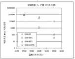
图1-4示出了一些实施例,它们显示了根据本发明可实现的气泡含量和温度分布,Figures 1-4 illustrate some examples showing the gas bubble content and temperature distributions achievable according to the invention,
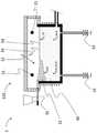
图5在纵剖面图中示范性地示出了熔融装置,Figure 5 shows an exemplary melting device in longitudinal section,
图6在另一个实施方式中在纵剖面图中示意性地示出了熔融装置,FIG. 6 schematically shows a melting device in longitudinal section in another embodiment,
图7在纵剖面图中示意性地示出了具有熔槽和精炼槽的熔融装置的另一个实施方式,FIG. 7 schematically shows another embodiment of a melting device with a melting tank and a refining tank in longitudinal section,
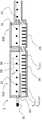
图8在俯视图中示出了具有侧电极的两部分式熔融装置的另一个实施方式,FIG. 8 shows another embodiment of a two-part fusion device with side electrodes in top view,
图9在纵剖面图中示出了来自图8中的熔融装置,Figure 9 shows the melting device from Figure 8 in longitudinal section,
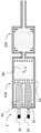
图10在俯视图中示出了具有侧电极的两部分式熔融装置的另一个实施方式,该熔融装置具有大于25吨/天的熔融能力,其中,电极以横向布置设置在熔槽中,FIG. 10 shows in top view another embodiment of a two-part melting device with side electrodes having a melting capacity of more than 25 t/day, wherein the electrodes are arranged in a transverse arrangement in the melting tank,
图11在纵剖面图中示出了来自图10中的实施方式,FIG. 11 shows the embodiment from FIG. 10 in longitudinal section,
图12在俯视图中示出了具有侧电极的两部分式熔融装置的另一个实施方式,该熔融装置具有大于25吨/天的熔融能力,其中,电极以纵向布置设置在熔槽中,和Figure 12 shows in top view another embodiment of a two-part melting device with side electrodes having a melting capacity of more than 25 tons/day, wherein the electrodes are arranged in a longitudinal arrangement in the melting tank, and
图13在纵剖面图中示出了来自图12中的实施方式。FIG. 13 shows the embodiment from FIG. 12 in longitudinal section.
具体实施方式Detailed ways
在以下优选实施方式的详细描述中,为了清楚起见,相同的附图标记表示在这些实施方式中或上的基本上相同的部分。但是,为了更好地说明本发明,在附图中所示的优选实施方式并不总是按比例绘制。In the following detailed description of the preferred embodiments, like reference numerals refer to substantially like parts in or on these embodiments for the sake of clarity. However, in order to better illustrate the invention, the preferred embodiments shown in the drawings are not always drawn to scale.
根据本发明的用于由玻璃熔体优选连续地生产玻璃产品的方法包括以下步骤:The method according to the invention for the preferably continuous production of glass products from a glass melt comprises the following steps:
-提供玻璃原料,特别是混合物和/或碎玻璃,- supply of glass raw materials, especially mixtures and/or cullets,
-在熔融装置中加热玻璃原料,其中,熔融装置包括用于由玻璃原料产生玻璃熔体的熔槽和顶炉,其中,熔融装置的熔融区的表面的至少一部分被玻璃原料覆盖并且熔融区的表面的至少一小部分没有被覆盖,- heating of glass raw material in a melting device, wherein the melting device comprises a melting tank and a top furnace for producing a glass melt from glass raw material, wherein at least a part of the surface of the melting zone of the melting device is covered by glass raw material and the melting zone At least a small portion of the surface is not covered,
-这样地加热熔融装置,使得在熔融装置的自由表面下方在底部处的玻璃熔体的温度TG_BOD和在顶炉中的气氛的温度TO分别至少为1300℃,其中,建立至少50℃的垂直温差TG_BOD-TO,并且其中,在底部处的玻璃熔体的温度大于在顶炉中的气氛的温度,因此有:TG_BOD>TO,- Heating the melting device in such a way that the temperature TG_BOD of the glass melt at the bottom below the free surface of the melting device and the temperature TO of the atmosphere in the top furnace are each at least 1300° C., wherein a temperature of at least 50° C. is established vertical temperature difference TG_BOD - TO , and where the temperature of the glass melt at the bottom is greater than the temperature of the atmosphere in the top furnace, so: TG_BOD > TO ,
-从熔槽中排出玻璃熔体,其中,排出的玻璃熔体具有优选少于1000个/公斤的直径大于50μm的气泡。- Discharge of the glass melt from the melting tank, wherein the discharged glass melt has preferably less than 1000/kg bubbles with a diameter greater than 50 μm.
本方法以能量输入的优化为基础,其目的在于这样地改善在熔融玻璃原料期间的流动情况,即可以提高槽产量。The method is based on an optimization of the energy input, the aim of which is to improve the flow conditions during melting of the raw glass materials in such a way that the tank output can be increased.
通过能量输入影响用于玻璃的熔融装置的非常重要的参数。在下面所示的表1中对用于示范性选择的熔融装置的各种重要参数进行对比。这些参数是:A very important parameter of the melting device for glass is influenced by the energy input. Various important parameters for an exemplary selection of melting apparatuses are compared in Table 1 shown below. These parameters are:
TP:产量,以吨/天[t/d]为单位来测量,TP: Production, measured in tons per day [t/d],
MA:熔融面积,供玻璃熔体使用的熔槽容积的表面,以m2为单位来测量,Spec.MA:比熔融面积[t/m2/d],MA: melting area, the surface of the melting tank volume used by the glass melt, measured in m2 , Spec.MA: specific melting area [t/m2 /d],
tmin:熔融设备的最短停留时间,以小时[h]为单位,定义在示踪物质的输入与在排出点处的第一次浓度增加之间的时间,tmin : minimum residence time of the melting plant in hours [h], defining the time between the input of the tracer substance and the first concentration increase at the discharge point,
tgeo:熔融设备的平均几何停留时间,以小时[h]为单位,由槽容积和容积流率计算得出,tgeo : mean geometric residence time of the melting apparatus in hours [h], calculated from tank volume and volumetric flow rate,
tgeo/tmin:在熔槽中的玻璃熔体的最小停留时间tmin与在熔槽中的玻璃熔体的平均几何停留时间tmg之比。tgeo /tmin : the ratio of the minimum residence time tmin of the glass melt in the melting tank to the average geometric residence time tmg of the glass melt in the melting tank.


表1:选择的熔槽的产量、熔融面积和停留时间Table 1: Capacity, melting area and residence time of selected melting tanks
列出的信息来源于以下文献:The information listed comes from the following literature:
1)Schippan,D.:Untersuchung des reaktionstechnischen Verhaltens in
槽A:第72,75和77-84页Slot A: pages 72, 75 and 77-84
槽B:第92,95,102-103页Slot B: pages 92, 95, 102-103
槽C:第109,111,116,120,122页Slot C: pages 109, 111, 116, 120, 122
槽D:第124页Slot D: page 124
2)Tecoglas,W.R.Seitz,C.W.Hibscher:“Design Considerations for All-electric Melters(全电熔融装置的设计考虑)”,1980年11月,俄亥俄州哥伦布市第41届玻璃问题会议,2) Tecoglas, W.R.Seitz, C.W.Hibscher: "Design Considerations for All-electric Melters", November 1980, 41st Glass Problems Conference, Columbus, Ohio,
3)Trier,W.:
4)Hippius,W.,Linz,H.-J.,Philipp,G.:“Untersuchung von
5)Bauer,J.:“Verweilzeitanalysen an einer Glasschmelzwanne(在玻璃熔槽上的停留时间分析)”,法兰克福,第1903号HVG Communication。5) Bauer, J.: "Verweilzeitanalysen an einer Glasschmelzwanne (residence time analysis on glass melting tanks)", Frankfurt, HVG Communication No. 1903.
在一览表中示出的用于熔槽的重要参数的示例显示了例如具有产量为14t/d(VESRasotherm玻璃)的较小和较大的装置,直至具有日产量高达355t/d(Schippan B2/0)的大型设备。在所选择的设备中,不同的玻璃被熔融并加工成不同的玻璃产品。因此,例如考虑浮法玻璃设备,但也考虑例如用于生产硼硅酸盐玻璃制品的较小的设备。Examples of important parameters for melting tanks shown in the overview show for example smaller and larger installations with a production capacity of 14 t/d (VESRasotherm glass) up to a daily production capacity of up to 355 t/d (Schippan B2/0 ) large equipment. In the selected equipment, different glasses are melted and processed into different glass products. Thus, for example, float glass plants are conceivable, but also smaller plants, for example for the production of borosilicate glass products.
最小停留时间tmin为至少2小时,直至具有超过11小时的设备;几何停留时间tgeo为介于19.5小时直至超过60小时之间的值。由此产生3.7直至如10这样的值的比值tgeo/tmin。The minimum residence time tmin is at least 2 hours, up to equipment with more than 11 hours; the geometric residence time tgeo is a value between 19.5 hours up to more than 60 hours. This results in a ratio tgeo /tmin of 3.7 up to a value such as 10.
但是,在此应该考虑的是,可实现的值始终应该在与可达到的玻璃质量的结合中来看。作为示例提及的具有小的值的设备在这种情况下没有达到所要求的玻璃质量,如这特别地是本发明的一个关注点。在没有稳定的质量的情况下单独增加产量最终会导致较低的熔融效率。However, it should be taken into account here that the achievable values should always be seen in combination with the achievable glass quality. Devices with small values mentioned as examples do not achieve the required glass quality in this case, as this is in particular a concern of the present invention. Increasing throughput alone without consistent quality will eventually lead to lower melting efficiency.
表2示出了在来自表1中的所选的示例性熔融装置中的温度分布。在表2中总结了以下的值:Table 2 shows the temperature profiles in selected exemplary melting apparatuses from Table 1 . The following values are summarized in Table 2:
TGuG:在混合物下方的玻璃温度。借助于浸入式热电偶从上方20cm穿过混合物来测量,或者替代地,借助于数学模拟模型来计算。TGuG : glass temperature below the mixture. Measured by means of an immersion thermocouple through the mixture from above 20 cm, or alternatively calculated by means of a mathematical simulation model.
TGuG_Bod:在底部处的混合物下面的玻璃温度。借助于引导通过熔融设备的底部的热电偶来测量,热电偶的尖端布置成与玻璃直接接触。TGuG_Bod : Glass temperature below the mixture at the bottom. It is measured by means of a thermocouple guided through the bottom of the melting apparatus, the tip of the thermocouple being arranged in direct contact with the glass.
TG_OF:在自由的玻璃浴表面上的玻璃温度,即没有混合物覆盖。借助于浸入式热电偶从上方来测量或借助于具有小于玻璃渗透深度的波长的高温计来测量。TG_OF : Glass temperature on the free glass bath surface, ie without mixture coverage. It is measured from above by means of an immersion thermocouple or by means of a pyrometer with a wavelength smaller than the penetration depth of the glass.
TG_Bod:在自由的玻璃浴表面下面在底部处的玻璃温度。借助于引导通过熔融设备的底部的热电偶来测量,热电偶的尖端布置成与玻璃直接接触。TG_Bod : glass temperature at the bottom below the free glass bath surface. It is measured by means of a thermocouple guided through the bottom of the melting apparatus, the tip of the thermocouple being arranged in direct contact with the glass.
TO:在用混合物覆盖的玻璃表面上方的区域中的顶炉温度(=拱顶温度)。借助于引导通过熔融设备的拱顶(或侧壁)的热电偶来测量,热电偶的尖端一直突入到炉腔中。TO : Top furnace temperature (= dome temperature) in the region above the glass surface covered with the mixture. It is measured by means of a thermocouple guided through the dome (or side wall) of the melting apparatus, the tip of the thermocouple protruding all the way into the furnace cavity.

表2:示例槽的温度Table 2: Temperatures of example tanks
在下面的表3中总结了用于根据本发明的具有重要参数的熔融装置的成功实施例,因此它们反映了技术上的教导。主要显示了:In table 3 below are summarized successful examples for a melting device according to the invention with important parameters, so that they reflect the technical teaching. Mainly shows:
气泡含量_SW:在熔融区或熔槽的出口处的以气泡/公斤为单位的玻璃质量。在评估中包括具有尺寸为约50μm或更大且至多1000μm的气泡,其中,该尺寸应理解为气泡在任一个方向上的最大伸展。Bubble content_SW: glass mass in bubbles/kg at the outlet of the melting zone or tank. Bubbles having a size of about 50 μm or more and up to 1000 μm, where size is understood to be the maximum stretch of the bubble in either direction, are included in the evaluation.
气泡含量_LW:在精炼区或精炼槽的出口处的以气泡/公斤为单位的玻璃质量。Bubble content_LW: glass mass in bubbles/kg at the outlet of the refining zone or refining tank.
覆盖率_SW:以%计的熔融区或熔槽的表面的用混合物覆盖的面积与熔融区或熔槽的总面积的比例。Coverage_SW: The ratio in % of the area of the surface of the fusion zone or bath covered with the mixture to the total area of the fusion zone or bath.
所示的实施例1-5涉及不同玻璃类型的玻璃产品的生产。所示的实施例1-4的日产量相当小,相当小的熔融面积也表明了这一点。在这些实施例中,覆盖率覆盖率_SW被选择得相对较高并且为至少40%或更多并且直至60%,也就是说,超过一半的供使用的表面被玻璃原料覆盖。Examples 1-5 shown relate to the production of glass products of different glass types. The daily throughputs shown for Examples 1-4 are rather small, as indicated by the relatively small areas of fusion. In these embodiments, the coverage coverage_SW is chosen relatively high and is at least 40% or more and up to 60%, that is to say more than half of the surface available for use is covered by glass frit.
由此产生停留时间tgeo/tmin的极低的比率,该比率最大值为3.1并且一直向下降到1.9的值并因此非常接近理想值1.0。This results in an extremely low ratio of the residence time tgeo /tmin which has a maximum value of 3.1 and drops down to a value of 1.9 and is therefore very close to the ideal value of 1.0.
在熔融区的末端处的玻璃质量处在300个气泡/公斤的范围内,在某些情况下甚至显著低于该范围。在实施例中规定,供给玻璃进行精炼。这在1640℃(示例1-4)或1600℃(示例5)的温度下进行。结果表明,在精炼之后可以达到小于1个气泡/公斤、优选小于0.1个气泡/公斤的非常高的质量。The glass mass at the end of the melting zone is in the range of 300 bubbles/kg, and in some cases even significantly below this range. In the examples it is provided that glass is supplied for refining. This was done at a temperature of 1640°C (Examples 1-4) or 1600°C (Example 5). The results show that a very high quality of less than 1 bubble/kg, preferably less than 0.1 bubbles/kg can be achieved after refining.

表3:用于根据本发明的熔融装置的成功实施例Table 3: Successful examples for melting devices according to the invention
最后,在表4中总结了其他实施例,这些实施例是不成功的。在此,选择了明显更低的覆盖度,其大约在10%和30%之间。结果表明,tgeo/tmin的比率基本上是明显更不利的。例如,在覆盖度为10-20%的情况下,只能达到6.1的tgeo/tmin比率。Finally, other examples, which were unsuccessful, are summarized in Table 4. Here, a significantly lower coverage level of approximately between 10% and 30% is selected. It turns out that the ratio tgeo /tmin is essentially significantly more unfavorable. For example, at a coverage of 10-20%, only a tgeo /tmin ratio of 6.1 can be achieved.
而且,尽管也在1640℃的温度下进行了精炼,但可达到的玻璃质量明显较差。在这里可以观察到,气泡含量、即在熔融区或熔槽的出口处测量的气泡/公斤的数值比来自成功实施例中的气泡含量高出好几个级别,在最好的情况下为约8000气泡/公斤,而且甚至高达100000气泡/公斤。在精炼之后的玻璃中也发现明显多于1气泡/公斤。Moreover, although refining was also carried out at a temperature of 1640°C, the achievable glass was of significantly lower quality. Here it can be observed that the bubble content, i.e. the value of bubbles/kg measured at the outlet of the melting zone or melt tank, is several orders of magnitude higher than the bubble content from the successful examples, in the best case around 8000 bubbles/kg, and even up to 100,000 bubbles/kg. Significantly more than 1 bubble/kg was also found in the glass after refining.

表4:不成功的实施例Table 4: Unsuccessful Examples
优选的实施例在图1-4中示出。在此,图1至4示出了一些实施例,这些实施例显示了对于根据表3和4的所选玻璃类型A、B、C和D根据本发明可达到的气泡含量和温度分布。A preferred embodiment is shown in Figures 1-4. Here, FIGS. 1 to 4 show examples showing the gas bubble content and temperature distribution achievable according to the invention for selected glass types A, B, C and D according to Tables 3 and 4 .
以下的图5至13示出了根据本发明的熔融装置的实施例。5 to 13 below show an embodiment of a melting device according to the invention.
图5在纵剖面图中示范性地示出了在整体上用附图标记1标示的熔融装置。仅作为示例而不限于该实施例地示出的熔融装置1是两部分式设计并且在该实施方式中包括熔槽10以及精炼槽20,其中,两个槽各具有在结构上分开的顶炉12、22。在顶炉12、22的区域中布置有气体燃烧器11、21,它们固定在顶炉11、21的侧壁上。在该示例中,为了清楚起见,仅各示出了两个气体燃烧器11、21。当然,不同数量的气体燃烧器11、21也是可行的并且在较大尺寸的熔融装置1中确实合适的,其中,数量和布置取决于期望的能量输入和/或顶炉12、22的几何形状和尺寸。FIG. 5 shows an example of a melting device, designated as a whole by the
示意性地示出了供给装置31,通过该供给装置可以将玻璃原料引入装载区中,该装载区在该示例中被集成到熔槽10中。熔槽10限定一个容积,该容积被设计用于熔融已装入的玻璃原料。在所示的示例中,该容积14用玻璃熔体30填充,即用至少部分熔融的玻璃原料填充。在用玻璃原料填充的阶段中,容积14的表面形成所谓的玻璃线33。A
在该示例中,熔槽10还配备有两个底部排放口13,该底部排放口允许将液态的玻璃熔体向下放出。In this example, the
精炼槽20也具有用于容纳玻璃熔体30的容积24。两个容积14、24通过输入管道15彼此连接,输入管道也称为流动通路。在该示例中,精炼槽20也设计成具有底部排出口23,通过该底部排出口可以放出均匀且精炼的玻璃熔体。The
通过在图5中所示的熔融装置1,该熔融装置包括熔槽10和精炼槽20,确定了在上面示出的表3和4中所示的、针对熔融装置的温度和工艺控制设定的成功示例(示例1a-4)和不成功示例(示例6-10b)的参数。With the
在表中示出的示例描述了在相同的熔融能力但不同的工艺温度的情况下在所检测的玻璃类型的玻璃质量上的差异。The examples shown in the table describe the differences in glass quality for the tested glass types with the same melting capacity but different process temperatures.
与不成功的示例6至10b相比,成功的示例1a至4显示,在相同的结构尺寸的熔融装置1的情况下,当使用根据本发明的最佳温度时,可以实现负荷增加2倍或甚至更多。因此,在熔融装置1的根据本发明的温度或工艺控制的情况下,可以将约0.8t/m2/d的比熔融能力增加至大于2t/m2/d的比熔融能力。Compared with the unsuccessful examples 6 to 10b, the successful examples 1a to 4 show that, with the same structural dimensions of the
图6在熔槽110的另一个实施方式的纵剖面图中示意性地示出了熔融装置1,用于解释作为工艺模型的工艺控制。通过供给装置31将玻璃原料引入到熔槽110中,玻璃原料在装载区中形成混合物毯32。该混合物毯32在玻璃线33的高度处部分地覆盖玻璃熔体的表面。在所示的示例中,该表面大约1/3被装入的、大部分尚未被熔融的玻璃原料覆盖。在这种情况下,混合物毯32的厚度在生产方向上看减小,也就是说,它在装载区中是最大的。FIG. 6 schematically shows a
在图6中,此外示意性地示出了几个作为用于确定用于工艺控制(Verfahrensführung)的相关温度的测量点的区域。在该相关温度中包括在顶炉中的温度TO、在混合物下面的玻璃温度TGuG、在底部处在混合物下面的玻璃温度TG_BOD、在自由的玻璃浴表面处的玻璃温度TG_OF、和在底部处在自由的玻璃浴表面下面的区域中的玻璃温度TG_Bod。在混合物毯32与自由的表面之间的边界区域在处理过程中通常是流动的。玻璃熔体的自由表面、即作为自由的玻璃浴表面34在此被理解为一个这样的表面区域,即该表面区域基本上不含有未熔融的玻璃原料,特别地,该表面区域在小于80%、优选地小于70%和特别优选地小于60%的程度上被未熔融的玻璃原料覆盖。因此,被称为自由的玻璃熔体表面的至少20%、优选地至少30%和特别优选地至少40%不含有混合物和/或碎玻璃。FIG. 6 also schematically shows several regions as measuring points for determining the relevant temperature for process control. Among the relevant temperatures are the temperature TO in the top furnace, the glass temperature T GuG below the mixture, the glass temperature TG_BOD below the mixture at the bottom, the glass temperature TG_OF at the surface of the free glassbath , and Glass temperature TG — Bod in the region below the free glass bath surface at the bottom. The border region between the
图7在具有熔槽210和精炼槽220的纵剖面图中示意性地示出了熔融装置1的另一个实施方式。在该实施方式的设备中确定了在表3和4中的根据示例5的参数。熔槽210和精炼槽220各自具有气体燃烧器11、21,它们布置在顶炉12、22的区域中。顶炉12、22在结构上被浸入隔板41分开,该浸入隔板从顶炉12、22的拱顶一直突入到玻璃熔体30中。FIG. 7 schematically shows another embodiment of the
示意性地示出了被设计成侧电极的块或板电极16,该块或板电极被布置在熔槽210的玻璃熔体的区域中。在熔槽210和精炼槽220之间还设置了溢流壁42,该溢流壁的上边缘位于玻璃线33下方,从而玻璃熔体可以到达精炼槽220中。此外,设置了用于放出被精炼的玻璃的流动通路43。示出的气体燃烧器11、21以及块或板电极16的数量仅仅是被选择用于说明布置和安装位置并且在实际的熔融装置中可以与其有偏差。A block or
图8和图9在另外的视图中示出了来自图7中的熔融装置的结构。图8在俯视图中示出了两部分式熔融装置1,而图9在纵剖面图中示出了同一个熔融装置1。示范性示出的熔融装置1包括熔槽210以及精炼槽220,它们通过流动通路15彼此连接。在图8中所示的俯视图中,可以很好地看到板电极16不仅在熔槽210的两个侧壁上而且在熔槽210的端面上的布置。8 and 9 show the structure of the melting device from FIG. 7 in further views. FIG. 8 shows a two-
在图9中可以看到,这些板电极16被安装在玻璃线33下方。混合物毯32在该示例中更大并且包括玻璃熔体30的大约一半的表面。也示出了在其中确定用于工艺控制的相关的熔融装置1的温度的区域。It can be seen in FIG. 9 that these
图10和11示出了具有侧电极的两部分式熔融装置1的另一个实施方式,该熔融装置具有大于25吨/天的熔融能力。电极16在该示例中被设计成棒状电极并且在横向布置下设置在熔槽310中,其中,电极16通过在熔槽310的底部中的开口突入到玻璃熔体30中并且通过这种方式,对靠近底部的玻璃熔体也允许高度精确的温度控制。附加地,在顶炉中,不仅在熔槽310中而且在精炼槽320中都设置石化加热装置,在示例中形式为气体燃烧器11、21。Figures 10 and 11 show another embodiment of a two-
最后,图12和13示出了具有侧电极的两部分式熔融装置1的另一个实施方式,该熔融装置具有大于25吨/天的熔融能力。电极16在该示例中也被设计成棒状电极并且在纵向布置下设置在熔槽410中,其中,电极16通过在熔槽410的底部中的开口突入到玻璃熔体30中并且通过这种方式,对靠近底部的玻璃熔体也允许高度精确的温度控制。附加地,在顶炉中,不仅在熔槽410在而且在精炼槽420中都设置有石化加热装置,其在示例中形式为气体燃烧器11、21。Finally, FIGS. 12 and 13 show another embodiment of a two-
Claims (42)
Translated fromChineseApplications Claiming Priority (2)
| Application Number | Priority Date | Filing Date | Title |
|---|---|---|---|
| DE102018108418.8 | 2018-04-10 | ||
| DE102018108418.8ADE102018108418A1 (en) | 2018-04-10 | 2018-04-10 | Process for the preparation of glass products and apparatus suitable for this purpose |
Publications (2)
| Publication Number | Publication Date |
|---|---|
| CN110357399A CN110357399A (en) | 2019-10-22 |
| CN110357399Btrue CN110357399B (en) | 2022-12-02 |
Family
ID=66102526
Family Applications (1)
| Application Number | Title | Priority Date | Filing Date |
|---|---|---|---|
| CN201910285846.7AActiveCN110357399B (en) | 2018-04-10 | 2019-04-10 | Method for producing glass products and device suitable therefor |
Country Status (5)
| Country | Link |
|---|---|
| US (1) | US20190308899A1 (en) |
| EP (1) | EP3553034B1 (en) |
| CN (1) | CN110357399B (en) |
| DE (1) | DE102018108418A1 (en) |
| MY (1) | MY200617A (en) |
Families Citing this family (4)
| Publication number | Priority date | Publication date | Assignee | Title |
|---|---|---|---|---|
| US20200055772A1 (en)* | 2017-02-21 | 2020-02-20 | Central Glass Company, Limited | Method for manufacturing color coated plate glass |
| DE102019217977A1 (en)* | 2019-11-21 | 2021-05-27 | Schott Ag | Glass, a method for making a glass and a glass melting plant |
| CN115605442B (en)* | 2020-03-05 | 2024-10-01 | 肖特股份有限公司 | Method and apparatus for melting glass |
| EP4063332A1 (en)* | 2021-03-22 | 2022-09-28 | Schott Ag | Method of making high quality glass products from high viscosity melts |
Citations (4)
| Publication number | Priority date | Publication date | Assignee | Title |
|---|---|---|---|---|
| US3574585A (en)* | 1968-08-19 | 1971-04-13 | Brockway Glass Co Inc | Electric glass melting furnace and method of melting glass |
| US5352258A (en)* | 1993-03-31 | 1994-10-04 | Ppg Industries, Inc. | Production of glass fibers from scrap glass fibers |
| WO2007085397A1 (en)* | 2006-01-24 | 2007-08-02 | Schott Ag | Method and device for the corrosion protection of electrodes when influencing the temperature of a melt |
| CN104144890A (en)* | 2012-02-22 | 2014-11-12 | 肖特公开股份有限公司 | Method for producing glasses, glass ceramics and the use of same |
Family Cites Families (11)
| Publication number | Priority date | Publication date | Assignee | Title |
|---|---|---|---|---|
| GB835201A (en)* | 1955-02-22 | 1960-05-18 | Elemelt Ltd | A method of and furnace for refining glass |
| ES2047074T3 (en)* | 1988-09-10 | 1994-02-16 | Sorg Gmbh & Co Kg | PROCEDURE FOR THE TRANSFORMATION INTO GLASS OF SOLID MATERIALS OF WASTE, IN LARGE PART WITHOUT WATER, AS WELL AS A DEVICE FOR CARRYING OUT THE PROCEDURE. |
| US4919698A (en)* | 1989-06-21 | 1990-04-24 | Ppg Industries, Inc. | Avoidance of nickel sulfide stones in a glass melting operation |
| US5922097A (en)* | 1996-06-12 | 1999-07-13 | Praxair Technology, Inc. | Water enhanced fining process a method to reduce toxic emissions from glass melting furnaces |
| DE19939772C1 (en)* | 1999-08-21 | 2001-05-03 | Schott Glas | Skull crucible for melting or refining glasses |
| DE10116293A1 (en) | 2001-03-31 | 2002-10-10 | Schott Glas | Accelerated melting and better process controllability |
| DE10314955B4 (en)* | 2003-04-02 | 2008-04-17 | Schott Ag | Process for melting inorganic materials |
| DE102005039919B9 (en) | 2005-08-24 | 2010-01-21 | Schott Ag | Process for refining a glass melt |
| DE102009002336B4 (en)* | 2009-04-09 | 2012-09-20 | Schott Ag | Method and device for refining a glass melt |
| FR2973797B1 (en)* | 2011-04-06 | 2018-10-05 | Fives Stein | GLASS OVEN, IN PARTICULAR FOR CLEAR OR ULTRA-CLEAR GLASS, WITH SIDE SECONDARY RECIRCULATIONS |
| KR102569272B1 (en)* | 2017-09-13 | 2023-08-22 | 니폰 덴키 가라스 가부시키가이샤 | Manufacturing method of glass article |
- 2018
- 2018-04-10DEDE102018108418.8Apatent/DE102018108418A1/ennot_activeWithdrawn
- 2019
- 2019-04-02MYMYPI2019001850Apatent/MY200617A/enunknown
- 2019-04-08EPEP19167871.3Apatent/EP3553034B1/enactiveActive
- 2019-04-09USUS16/379,332patent/US20190308899A1/ennot_activeAbandoned
- 2019-04-10CNCN201910285846.7Apatent/CN110357399B/enactiveActive
Patent Citations (4)
| Publication number | Priority date | Publication date | Assignee | Title |
|---|---|---|---|---|
| US3574585A (en)* | 1968-08-19 | 1971-04-13 | Brockway Glass Co Inc | Electric glass melting furnace and method of melting glass |
| US5352258A (en)* | 1993-03-31 | 1994-10-04 | Ppg Industries, Inc. | Production of glass fibers from scrap glass fibers |
| WO2007085397A1 (en)* | 2006-01-24 | 2007-08-02 | Schott Ag | Method and device for the corrosion protection of electrodes when influencing the temperature of a melt |
| CN104144890A (en)* | 2012-02-22 | 2014-11-12 | 肖特公开股份有限公司 | Method for producing glasses, glass ceramics and the use of same |
Also Published As
| Publication number | Publication date |
|---|---|
| DE102018108418A1 (en) | 2019-10-10 |
| CN110357399A (en) | 2019-10-22 |
| EP3553034A1 (en) | 2019-10-16 |
| US20190308899A1 (en) | 2019-10-10 |
| EP3553034B1 (en) | 2023-08-09 |
| MY200617A (en) | 2024-01-05 |
Similar Documents
| Publication | Publication Date | Title |
|---|---|---|
| CN110357399B (en) | Method for producing glass products and device suitable therefor | |
| KR920003938B1 (en) | Method and apparatus for melting, refining and homogenizing glass | |
| US11919798B2 (en) | Gradient fining tank for refining foamy molten glass and a method of using the same | |
| JP2583101B2 (en) | Glass melting furnace and glass manufacturing method | |
| JP5323833B2 (en) | Method and apparatus for controlling the liquid level of a molten material in a glass manufacturing system | |
| US11485664B2 (en) | Stilling vessel for submerged combustion melter | |
| US7296441B2 (en) | Device and method for melting a substance with the occurrence of a low level of contamination | |
| JPS63195129A (en) | Method and equipment for forming laminated glass vessel from molten glass compositely sealed seed | |
| CN106660854B (en) | Apparatus for melting glass including furnace, channel and baffle | |
| KR20190078631A (en) | Apparatus and method for forming a glass article | |
| CZ307659B6 (en) | The melting space of the continuous glass melting furnace and the method of melting glass in this space | |
| US4504302A (en) | Homogenizing apparatus glass making furnace and method of homogenizing glass | |
| Jebava et al. | Role of glass melt flow in container furnace examined by mathematical modelling | |
| KR102017037B1 (en) | Method for drawing vitrifiable materials | |
| KR20190049756A (en) | Apparatus and method for manufacturing glass articles | |
| JP6943136B2 (en) | Glass melting furnace and manufacturing method of glass articles | |
| EP2499101B1 (en) | Melting method and apparatus | |
| EP4051645B1 (en) | Glass fining using an objective and molten metal | |
| CN104986940B (en) | Glass melting set and its melting method increased the service life | |
| WO1985000801A1 (en) | Manufacture of glass articles | |
| EP4345069A1 (en) | A vessel system for producing and refining a glass melt, and method for producing and refining a glass melt | |
| EP4530263B1 (en) | A melting vessel for glass melting, and a method for making a glass melt | |
| WO2025068384A1 (en) | A vessel system for producing and refining a glass melt, and method for producing and refining a glass melt | |
| WO1983004245A1 (en) | Homogenizing apparatus and glass making furnace | |
| JPH01164735A (en) | Method for melting glass |
Legal Events
| Date | Code | Title | Description |
|---|---|---|---|
| PB01 | Publication | ||
| PB01 | Publication | ||
| SE01 | Entry into force of request for substantive examination | ||
| SE01 | Entry into force of request for substantive examination | ||
| GR01 | Patent grant | ||
| GR01 | Patent grant |