CN110351475B - Image pickup system, information processing apparatus, control method therefor, and storage medium - Google Patents
Image pickup system, information processing apparatus, control method therefor, and storage mediumDownload PDFInfo
- Publication number
- CN110351475B CN110351475BCN201910265973.0ACN201910265973ACN110351475BCN 110351475 BCN110351475 BCN 110351475BCN 201910265973 ACN201910265973 ACN 201910265973ACN 110351475 BCN110351475 BCN 110351475B
- Authority
- CN
- China
- Prior art keywords
- imaging
- area
- image
- unit
- camera
- Prior art date
- Legal status (The legal status is an assumption and is not a legal conclusion. Google has not performed a legal analysis and makes no representation as to the accuracy of the status listed.)
- Active
Links
- 238000000034methodMethods0.000titleclaimsabstractdescription28
- 238000003860storageMethods0.000titleclaimsabstractdescription15
- 230000010365information processingEffects0.000titleclaimsabstractdescription10
- 238000003384imaging methodMethods0.000claimsabstractdescription346
- 238000012545processingMethods0.000claimsdescription29
- 230000008859changeEffects0.000abstractdescription12
- 230000003287optical effectEffects0.000description21
- 238000010586diagramMethods0.000description12
- 230000008569processEffects0.000description9
- 230000006870functionEffects0.000description7
- 238000004891communicationMethods0.000description6
- 238000012937correctionMethods0.000description3
- 239000000470constituentSubstances0.000description2
- 238000009434installationMethods0.000description2
- 238000012544monitoring processMethods0.000description2
- 238000011017operating methodMethods0.000description2
- 238000004091panningMethods0.000description2
- 230000000295complement effectEffects0.000description1
- 230000006835compressionEffects0.000description1
- 238000007906compressionMethods0.000description1
- 238000005520cutting processMethods0.000description1
- 238000009826distributionMethods0.000description1
- 239000004973liquid crystal related substanceSubstances0.000description1
- 230000007246mechanismEffects0.000description1
- 229910044991metal oxideInorganic materials0.000description1
- 150000004706metal oxidesChemical class0.000description1
- 238000012986modificationMethods0.000description1
- 230000004048modificationEffects0.000description1
- 230000004044responseEffects0.000description1
- 239000004065semiconductorSubstances0.000description1
- 230000002194synthesizing effectEffects0.000description1
Images


Classifications
- H—ELECTRICITY
- H04—ELECTRIC COMMUNICATION TECHNIQUE
- H04N—PICTORIAL COMMUNICATION, e.g. TELEVISION
- H04N23/00—Cameras or camera modules comprising electronic image sensors; Control thereof
- H04N23/60—Control of cameras or camera modules
- H04N23/698—Control of cameras or camera modules for achieving an enlarged field of view, e.g. panoramic image capture
- H—ELECTRICITY
- H04—ELECTRIC COMMUNICATION TECHNIQUE
- H04N—PICTORIAL COMMUNICATION, e.g. TELEVISION
- H04N23/00—Cameras or camera modules comprising electronic image sensors; Control thereof
- H04N23/60—Control of cameras or camera modules
- H04N23/63—Control of cameras or camera modules by using electronic viewfinders
- H—ELECTRICITY
- H04—ELECTRIC COMMUNICATION TECHNIQUE
- H04N—PICTORIAL COMMUNICATION, e.g. TELEVISION
- H04N23/00—Cameras or camera modules comprising electronic image sensors; Control thereof
- H04N23/60—Control of cameras or camera modules
- H04N23/695—Control of camera direction for changing a field of view, e.g. pan, tilt or based on tracking of objects
- H—ELECTRICITY
- H04—ELECTRIC COMMUNICATION TECHNIQUE
- H04N—PICTORIAL COMMUNICATION, e.g. TELEVISION
- H04N23/00—Cameras or camera modules comprising electronic image sensors; Control thereof
- H04N23/90—Arrangement of cameras or camera modules, e.g. multiple cameras in TV studios or sports stadiums
- H—ELECTRICITY
- H04—ELECTRIC COMMUNICATION TECHNIQUE
- H04N—PICTORIAL COMMUNICATION, e.g. TELEVISION
- H04N23/00—Cameras or camera modules comprising electronic image sensors; Control thereof
- H04N23/60—Control of cameras or camera modules
- H04N23/62—Control of parameters via user interfaces
- H—ELECTRICITY
- H04—ELECTRIC COMMUNICATION TECHNIQUE
- H04N—PICTORIAL COMMUNICATION, e.g. TELEVISION
- H04N23/00—Cameras or camera modules comprising electronic image sensors; Control thereof
- H04N23/60—Control of cameras or camera modules
- H04N23/66—Remote control of cameras or camera parts, e.g. by remote control devices
- H04N23/661—Transmitting camera control signals through networks, e.g. control via the Internet
Landscapes
- Engineering & Computer Science (AREA)
- Multimedia (AREA)
- Signal Processing (AREA)
- Human Computer Interaction (AREA)
- Closed-Circuit Television Systems (AREA)
- Studio Devices (AREA)
Abstract
Description
Translated fromChinese技术领域technical field
本发明涉及摄像系统、信息处理设备、信息处理设备的控制方法和存储介质。The present invention relates to an imaging system, an information processing apparatus, a control method of the information processing apparatus, and a storage medium.
背景技术Background technique
已知广域监视应用和精确监视应用作为安装在城市中的监视照相机的监视应用。广域监视应用是意图用于监控发生了诸如事故等的事件的特定场所或追踪移动物体的路径的应用。精确监视应用是意图用于精确拍摄事件或特定被摄体的应用。Wide-area surveillance applications and precise surveillance applications are known as surveillance applications of surveillance cameras installed in cities. A wide-area surveillance application is an application intended to monitor a specific place where an event such as an accident has occurred or to track the path of a moving object. A precision surveillance application is an application intended to precisely capture an event or a specific subject.
然而,为了以单个监视照相机满足上述两个监视应用,需要提供一种能够在维持精确地拍摄图像所需的分辨率的同时对宽区域进行摄像的监视照相机。因此,针对能够实现上述两个监视应用的监视照相机可使用的图像传感器或光学透镜的性能受到限制。However, in order to satisfy the above-mentioned two surveillance applications with a single surveillance camera, there is a need to provide a surveillance camera capable of imaging a wide area while maintaining the resolution required to accurately capture images. Therefore, the performance of the image sensor or optical lens usable for a surveillance camera capable of realizing the above two surveillance applications is limited.
关于上述点,已知了一种监视系统,其使用意图用于通过使用多个照相机来监视宽区域的固定视角照相机(以下称为“广域照相机”)、以及意图用于精确拍摄所监视的宽区域周边的一部分范围的平摇-俯仰-变焦(PTZ)照相机(日本特开2006-128932)。PTZ照相机可以通过沿平摇方向或俯仰方向改变包括光学透镜和图像传感器的镜筒的朝向来改变摄像方向,使得可以根据来自用户的指示来调整摄像区域。此外,PTZ照相机可以通过沿图像传感器的光轴方向移动光学透镜的位置来执行变焦操作,使得可以根据用户操作来改变视角。Regarding the above point, there is known a monitoring system that uses a fixed-angle camera (hereinafter referred to as a "wide-area camera") intended for monitoring a wide area by using a plurality of cameras, and a camera intended to precisely photograph the monitored A pan-tilt-zoom (PTZ) camera of a partial range around a wide area (Japanese Patent Laid-Open No. 2006-128932). The PTZ camera can change the imaging direction by changing the orientation of the lens barrel including the optical lens and the image sensor in the pan direction or the tilt direction, so that the imaging area can be adjusted according to an instruction from the user. In addition, the PTZ camera can perform a zooming operation by moving the position of the optical lens in the optical axis direction of the image sensor, so that the angle of view can be changed according to a user operation.
主要已知两种操作方法作为用于上述PTZ照相机的用户操作方法。第一种操作方法是独立操作PTZ照相机的方法。具体地,PTZ照相机利用设置在专用于PTZ照相机的控制器上的按钮或操纵杆来操作,或者通过显示在画面上的图形用户界面(GUI)来操作(日本特开2015-141471)。在第二操作方法中,如日本特开2006-128932中所述,用户从广域照相机所拍摄的图像中选择用户想要精确地拍摄图像的范围。计算平摇/俯仰/变焦操作的控制量,并且基于计算结果来驱动包括在摄像设备中的预定马达,使得通过PTZ照相机来拍摄用户所选择的范围。在第二操作方法中,由于可以根据广域照相机所拍摄的图像来设置PTZ照相机的摄像区域,因此可以直观地执行操作。因此,可以将PTZ照相机的摄像区域瞬时调整到目标摄像区域。Two operating methods are mainly known as user operating methods for the above-described PTZ camera. The first method of operation is the method of operating the PTZ camera independently. Specifically, the PTZ camera is operated with a button or a joystick provided on a controller dedicated to the PTZ camera, or is operated through a Graphical User Interface (GUI) displayed on the screen (Japanese Patent Laid-Open No. 2015-141471). In the second operation method, as described in Japanese Patent Laid-Open No. 2006-128932, the user selects a range in which the user wants to accurately capture an image from images captured by a wide-area camera. The control amount of the pan/tilt/zoom operation is calculated, and a predetermined motor included in the imaging apparatus is driven based on the calculation result, so that the range selected by the user is photographed by the PTZ camera. In the second operation method, since the imaging area of the PTZ camera can be set according to the image captured by the wide-area camera, the operation can be performed intuitively. Therefore, the imaging area of the PTZ camera can be instantly adjusted to the target imaging area.
然而,利用第二操作方法,即使被描述为第二摄像单元的一个示例的PTZ照相机可以拍摄被描述为第一摄像单元的一个示例的广域照相机的摄像区域外侧的区域,第二摄像单元的摄像区域也局限于第一摄像单元的摄像区域内的区域。因此,在通过第二摄像单元对位于第一摄像单元的摄像区域的边界上的被摄体整体进行摄像并显示整个被摄体的情况下,无法使用上述的第二操作方法。另一方面,利用第一操作方法,难以将PTZ照相机的摄像区域直观地调整到目标摄像区域。However, with the second operation method, even if the PTZ camera described as an example of the second imaging unit can capture an area outside the imaging area of the wide-area camera described as an example of the first imaging unit, the The imaging area is also limited to an area within the imaging area of the first imaging unit. Therefore, when the entire subject located on the boundary of the imaging area of the first imaging unit is captured by the second imaging unit and the entire subject is displayed, the above-described second operation method cannot be used. On the other hand, with the first operation method, it is difficult to intuitively adjust the imaging area of the PTZ camera to the target imaging area.
发明内容SUMMARY OF THE INVENTION
本发明提供一种摄像系统,包括:第一摄像单元,其被配置为通过对所确定的摄像区域进行摄像来获取第一图像;第二摄像单元,其被配置为改变摄像方向或视角中的至少任一个;第一显示控制单元,其被配置为执行用于对显示有所述第一图像的指定画面进行显示的控制,其中通过所述指定画面能够指定包括与显示有所述第一图像的区域不同的区域的第一画面区域;摄像控制单元,其被配置为控制所述第二摄像单元,使得通过基于所述指定画面处所指定的所述第一画面区域来控制所述第二摄像单元的摄像方向或视角中的至少任一个,从而通过对与所述第一画面区域相对应的摄像区域进行摄像来获取第二图像;以及第二显示控制单元,其被配置为执行用于对通过所述摄像控制单元执行的控制所获取到的所述第二图像进行显示的控制。The present invention provides a camera system, comprising: a first camera unit configured to acquire a first image by photographing a determined camera area; a second camera unit configured to change the camera direction or the angle of view At least any one; a first display control unit configured to perform control for displaying a designated screen on which the first image is displayed, wherein the designated screen can specify that the first image is included and displayed through the designated screen a first screen area of an area different from an area; an imaging control unit configured to control the second imaging unit such that the second imaging unit is controlled by controlling the second imaging unit based on the first screen area designated at the designated screen at least any one of the imaging direction or the angle of view of the unit, so as to obtain a second image by imaging the imaging area corresponding to the first screen area; and a second display control unit configured to perform a The control of displaying the second image acquired by the control performed by the imaging control unit.
本发明提供一种信息处理设备,包括:第一显示控制单元,其被配置为执行用于显示指定画面的控制,其中在所述指定画面上显示有通过用于对所确定的摄像区域进行摄像的第一摄像单元所执行的摄像而获取到的第一图像,通过所述指定画面能够指定包括与显示有所述第一图像的区域不同的区域的第一画面区域;以及第二显示控制单元,其被配置为执行用于显示第二图像的控制,其中所述第二图像是通过控制能够改变摄像方向和视角中的至少任一个的第二摄像单元的摄像方向和视角中的至少任一个、从而通过所述第二摄像单元对与所述指定画面处所指定的所述第一画面区域相对应的摄像区域进行摄像而获取到的。The present invention provides an information processing apparatus including: a first display control unit configured to execute control for displaying a specified screen on which a display for imaging a determined imaging area is displayed a first image acquired by imaging performed by the first imaging unit, a first screen area including an area different from an area where the first image is displayed can be specified through the specifying screen; and a second display control unit , which is configured to perform control for displaying a second image by controlling at least any one of the imaging direction and the angle of view of the second imaging unit capable of changing at least any one of the imaging direction and the angle of view , thus obtained by the second imaging unit imaging the imaging area corresponding to the first screen area designated at the designated screen.
本发明提供一种信息处理设备的控制方法,包括:利用第一显示控制来执行用于显示指定画面的控制,其中在所述指定画面上显示有通过用于对所确定的摄像区域进行摄像的第一摄像单元所执行的摄像而获取到的第一图像,通过所述指定画面能够指定包括与显示有所述第一图像的区域不同的区域的第一画面区域;以及利用第二显示控制来执行用于显示第二图像的控制,其中所述第二图像是通过控制能够改变摄像方向和视角中的至少任一个的第二摄像单元的摄像方向和视角中的至少任一个、从而通过所述第二摄像单元对与所述指定画面处所指定的所述第一画面区域相对应的摄像区域进行摄像而获取到的。The present invention provides a control method of an information processing apparatus, comprising: using a first display control to execute a control for displaying a specified screen on which a control method for imaging a determined imaging area is displayed A first image acquired by imaging performed by the first imaging unit, a first screen area including an area different from an area in which the first image is displayed can be specified through the specifying screen; and a second display control is used to specify Performing control for displaying a second image by controlling at least any one of the imaging direction and the angle of view of the second imaging unit capable of changing at least any of the imaging direction and the angle of view, thereby passing the It is obtained by the second imaging unit imaging the imaging area corresponding to the first screen area designated at the designated screen.
本发明提供一种非暂时性计算机可读存储介质,其存储用于使计算机用作以下单元的程序,所述单元包括:第一显示控制单元,其被配置为执行用于显示指定画面的控制,其中在所述指定画面上显示有通过用于对所确定的摄像区域进行摄像的第一摄像单元所执行的摄像而获取到的第一图像,通过所述指定画面能够指定包括与显示有所述第一图像的区域不同的区域的第一画面区域;以及第二显示控制单元,其被配置为执行用于显示第二图像的控制,其中所述第二图像是通过控制能够改变摄像方向和视角中的至少任一个的第二摄像单元的摄像方向和视角中的至少任一个、从而通过所述第二摄像单元对与所述指定画面处所指定的所述第一画面区域相对应的摄像区域进行摄像而获取到的。The present invention provides a non-transitory computer-readable storage medium storing a program for causing a computer to function as a unit including: a first display control unit configured to execute control for displaying a specified screen , wherein a first image obtained by imaging performed by a first imaging unit for imaging the determined imaging area is displayed on the specified screen, and through the specified screen, it is possible to specify that the specified image includes and displays a first screen area of an area different from the area of the first image; and a second display control unit configured to perform control for displaying a second image that is capable of changing the imaging direction and at least any one of the imaging direction and the angle of view of the second imaging unit of at least any one of the viewing angles, so that the imaging area corresponding to the first screen area designated at the designated screen is determined by the second imaging unit obtained by taking pictures.
通过以下参考附图对典型实施例的说明,本发明的其它特征将变得明显。Other features of the present invention will become apparent from the following description of exemplary embodiments with reference to the accompanying drawings.
附图说明Description of drawings
图1A、1B和1C是示出根据一个实施例的摄像系统的结构的示例的框图。1A, 1B, and 1C are block diagrams showing an example of the structure of an imaging system according to one embodiment.
图2A和2B是示出根据一个实施例的摄像设备的外观的示例的图。2A and 2B are diagrams showing an example of the appearance of an image pickup apparatus according to an embodiment.
图3是示出根据一个实施例的摄像设备沿俯仰方向的摄像区域的示例的图。FIG. 3 is a diagram illustrating an example of an imaging area in a tilt direction of the imaging apparatus according to one embodiment.
图4是示出根据一个实施例的摄像设备沿平摇方向的摄像区域的示例的图。FIG. 4 is a diagram showing an example of an imaging area in a pan direction of the imaging apparatus according to one embodiment.
图5是示出根据一个实施例的指定画面的示例的图。FIG. 5 is a diagram illustrating an example of a designation screen according to one embodiment.
图6是示出根据一个实施例的指定画面的示例的图。FIG. 6 is a diagram illustrating an example of a designation screen according to one embodiment.
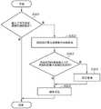
图7是示出根据一个实施例的摄像区域的设置处理的示例的流程图。FIG. 7 is a flowchart showing an example of setting processing of an imaging area according to one embodiment.
具体实施方式Detailed ways
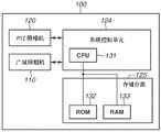
将参考图1A来描述摄像系统。图1A是示出摄像系统的结构的示例的框图。摄像系统包括摄像设备100和客户端设备140。摄像设备100和客户端设备140在相互可通信的状态下经由互联网协议(IP)网络130彼此连接。The camera system will be described with reference to FIG. 1A . FIG. 1A is a block diagram showing an example of the structure of an imaging system. The camera system includes a
摄像设备100包括广域照相机110、平摇-俯仰-变焦(PTZ)照相机120、系统控制单元124和存储单元125。The
广域照相机110包括摄像光学系统111、图像传感器单元112和图像处理单元113。The wide-
图像传感器单元112基于穿过摄像光学系统111的光来输出图像的电信号。图像传感器单元112包括电荷耦合器件(CCD)传感器或互补金属氧化物半导体(CMOS)传感器。广域照相机110是第一摄像单元的一个示例。The
图像处理单元113基于从图像传感器单元112输出的图像的电信号来执行所确定的图像处理。The
在图1A所示的示例中,在广域照相机110中仅示出一个摄像光学系统111和一个图像传感器单元112。然而,其数量不限于此,因而广域照相机110可以包括多个摄像光学系统111和图像传感器单元112。例如,广域照相机110可以包括多个照相机。这里,各照相机包括一个摄像光学系统111和一个图像传感器单元112。在广域照相机110包括多个照相机的情况下,广域照相机110可以通过对从各个照相机输出的图像进行合成并通过图像处理单元113生成全景图像来拍摄宽区域。构成广域照相机110的各照相机可以包括图像处理单元113。在这种情况下,系统控制单元124可以对各个照相机的输出图像进行合成以生成全景图像。广域照相机110以固定的视角拍摄图像。In the example shown in FIG. 1A , only one imaging
PTZ照相机120可以沿平摇方向和俯仰方向改变摄像方向,并且还通过改变视角来执行变焦。PTZ照相机120包括摄像光学系统121、图像传感器单元122、图像处理单元123、驱动控制单元126、变焦马达127、平摇马达128和俯仰马达129。PTZ照相机120是能够改变摄像方向和视角中的至少任一个的第二摄像单元的一个示例。The
摄像光学系统121包括调焦透镜或光圈机构(未示出)。摄像光学系统121由系统控制单元124控制,以在最佳曝光条件下拍摄图像。此外,摄像光学系统121可以通过变焦马达127来驱动被布置成可沿图像传感器单元122的光轴方向移动的光学透镜,以调整视角。The imaging
图像传感器单元122基于穿过摄像光学系统121的光来输出图像的电信号。图像传感器单元122包括CCD传感器或CMOS传感器。The
图像处理单元123基于从图像传感器单元122输出的图像的电信号来执行所确定的图像处理。The
驱动控制单元126基于系统控制单元124的控制来控制变焦马达127、平摇马达128和俯仰马达129,以改变PTZ照相机120的摄像方向或视角。系统控制单元124根据从客户端设备140接收到的控制命令来控制驱动控制单元126。通过上述控制,控制PTZ照相机120的摄像方向或视角,使得对用户通过客户端设备140的输入单元142所指定的摄像区域进行摄像。变焦马达127基于驱动控制单元126的控制使得摄像光学系统121的光学透镜在图像传感器单元122的光轴方向上移动。The
平摇马达128基于驱动控制单元126的控制使得PTZ照相机120的摄像方向在平摇方向上移动。The
俯仰马达129基于驱动控制单元126的控制使得PTZ照相机120的摄像方向在俯仰方向上移动。The
系统控制单元124通常控制摄像设备100的各构成元件,设置各种参数,并且控制相对于客户端设备140的通信。更具体地,系统控制单元124执行各种处理,诸如摄像控制、图像的压缩编码、图像剪切、输出图像的生成和网络分发等。系统控制单元124可以通过图像剪切来实现数字PTZ功能。The
如示出摄像设备100的结构的示例的图1B所示,系统控制单元124包括中央处理单元(CPU)131。此外,如图1B所示,存储单元125包括只读存储器(ROM)132和随机存取存储器(RAM)133。CPU 131将存储在ROM132中的程序加载到RAM 133并执行该程序,从而实现图7中的处理或由系统控制单元124执行的其它处理。RAM 133用作用于执行程序的工作区域以及各种数据和参数信息的存储区域。存储单元125包括非易失性存储器,使得各种数据或参数信息可以存储在非易失性存储器中。As shown in FIG. 1B showing an example of the structure of the
客户端设备140包括显示单元141、输入单元142、系统控制单元143和存储单元144。客户端设备140是信息处理设备的一个示例。The
显示单元141显示各种画面和图像。例如,液晶显示器用作显示单元141。The
输入单元142包括可由用户操作的鼠标和键盘。显示单元141可以包括触摸面板,并且用作输入单元142。The
系统控制单元143通常控制客户端设备140的各个构成元件,设置各种参数,并控制相对于摄像设备100的通信。The
如示出客户端设备140的结构的示例的图1C所示,系统控制单元143包括CPU 145。如图1C所示,存储单元144包括ROM 146和RAM 147。CPU 145将存储在ROM 146中的程序加载到RAM 147并执行该程序,从而实现由系统控制单元143所要执行的处理。RAM 147用作用于执行程序的工作区域以及各种数据和参数信息的存储区域。存储单元144包括非易失性存储器,使得程序和各种数据可以存储在非易失性存储器中。As shown in FIG. 1C showing an example of the structure of the
被视为摄像设备100的外部设备的诸如个人计算机(PC)或移动电话等的信息处理终端用作客户端设备140,但是客户端设备140不限于此。An information processing terminal such as a personal computer (PC) or a mobile phone, which is regarded as an external device of the
例如,IP网络130包括满足诸如以太网(Ethernet,注册商标)等的通信标准的多个路由器、交换机和线缆。然而,在本典型实施例中,只要摄像设备100和客户端设备140之间的通信可执行,就无需考虑IP网络130的通信标准、规模和配置。例如,IP网络130可以包括有线局域网(LAN)、无线LAN或广域网(WAN)。For example, the
客户端设备140的系统控制单元143经由IP网络130向摄像设备100发送各种控制命令。控制命令表示针对摄像设备100的指示。控制命令包括针对广域照相机110或PTZ照相机120的摄像参数的设置指示、针对摄像设备100的驱动组件的驱动控制指示、以及视频流传输开始/停止指示。摄像设备100的驱动组件包括变焦马达127、平摇马达128和俯仰马达129。The
摄像设备100的系统控制单元124经由IP网络130,从客户端设备140接收控制命令,并将对所接收到的控制命令的响应发送到客户端设备140。The
摄像设备100的系统控制单元124经由IP网络130将广域照相机110或PTZ照相机120所拍摄的图像分发到客户端设备140。客户端设备140的系统控制单元143控制显示单元141以显示从摄像设备100接收到的图像。通过该处理,用户可以浏览从摄像设备100分发的图像。此外,通过操作输入单元142,用户可以输入用于改变PTZ照相机120的摄像方向或视角的指示。The
接着,将参考图2A和2B来进一步描述摄像设备100。图2A是示出摄像设备100的侧面的示例的图。图2B是从下面描述的旋转部152侧观看的摄像设备100的俯视图。Next, the
摄像设备100包括固定部151和旋转部152。The
固定部151被固定到诸如天花板等的摄像设备100的安装场所。更具体地,固定部151具有安装面150并且安装面150被固定到天花板或专用附接构件,使得摄像设备100安装在天花板上。广域照相机110布置在固定部151上。广域照相机110基于摄像设备100的安装状态以固定视角来拍摄图像。在图2A所示的示例中,广域照相机110包括第一照相机110a、第二照相机110b和第三照相机110c。然而,构成广域照相机110的照相机的数量不限于三个,并且例如,广域照相机110可以包括四个以上的照相机,使得由此可以拍摄摄像设备100的整个周围的图像。可选地,广域照相机110可以由单个照相机构成,并且针对照相机的摄像光学系统111使用广角镜头,从而可以由此拍摄宽区域。The fixing
旋转部152布置在与固定部151的安装面150相对的一侧。旋转部152可以在通过使第一旋转轴156作为中心而指定的范围内旋转。例如,第一旋转轴156垂直于安装面150。The
PTZ照相机120布置在旋转部152上。当旋转部152绕第一旋转轴156旋转时,PTZ照相机120基于第一旋转轴156与旋转部152一起旋转。利用这种结构,PTZ照相机120沿图2B中的箭头158所示的平摇方向旋转,从而改变PTZ照相机120的摄像方向。这里,将被视为平摇方向上的基准的PTZ照相机120的摄像方向指定为图2B中的第一基准方向157。在本典型实施例中,PTZ照相机120的平摇角度可以在-90°至+90°之间的范围内变化。当第一基准方向157被指定为基准时,PTZ照相机120的平摇角度是平摇方向上的摄像角度。PTZ照相机120基于平摇角度的变化而旋转,以改变其摄像方向。PTZ照相机120的平摇角度的可变范围不限于-90°至+90°之间的范围,而可以是-5°至90°之间的范围,并且可以基于摄像设备100的构造来确定任意范围。平摇马达128使PTZ照相机120在平摇方向上旋转。The
此外,包括PTZ照相机120的摄像光学系统121和图像传感器单元122的镜筒159被配置为可绕垂直于第一旋转轴156的第二旋转轴153旋转。利用该结构,PTZ照相机120沿图2A中的箭头155指示的俯仰方向旋转,以改变PTZ照相机120的摄像方向。这里,将被视为俯仰方向上的基准的PTZ照相机120的摄像方向指定为图2A中的第二基准方向154。在本典型实施例中,PTZ照相机120的俯仰角度可以在-0°至+60°的范围内变化。当第二基准方向154被指定为基准时,PTZ照相机120的俯仰角度是俯仰方向上的摄像角度。PTZ照相机120基于俯仰角度的改变而旋转,以改变其摄像方向。PTZ照相机120的俯仰角度的可变范围不限于-0°至+60°之间的范围,而可以是-5°至90°之间的范围,并且可以基于摄像设备100的构造来确定任意范围。俯仰马达129使PTZ照相机120沿俯仰方向旋转。Further, the imaging
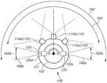
随后,将参考图3来描述摄像设备100沿俯仰方向的摄像区域。图3是示出摄像设备100沿俯仰方向的摄像区域的示例的图。Subsequently, an imaging area of the
图3中的可摄像区域160是指可以由PTZ照相机120进行摄像的摄像区域,并且PTZ照相机120可以通过改变俯仰角度来对可摄像区域160的一部分进行摄像。图3中的第一摄像区域160a是当PTZ照相机120的俯仰角度为0°时的俯仰方向上的摄像区域。此外,图3中的第二摄像区域160b是当PTZ照相机120的俯仰角度为+60°时的俯仰方向上的摄像区域。PTZ照相机120的俯仰角度可以在0°至+60°之间的范围内变化。因此,可以将可摄像区域160确定为第一摄像区域160a中的俯仰方向的负侧的摄像边界165a与第二摄像区域160b中的俯仰方向的正侧的摄像边界165b之间的范围。图3中的位置120a是当PTZ照相机120的俯仰角度为0°时的PTZ照相机120的位置。图3中的位置120b是当PTZ照相机120的俯仰角度为+60°时的PTZ照相机120的位置。The image-
摄像区域161是由广域照相机110恒定拍摄的俯仰方向上的范围。The
接着,将参考图4来描述摄像设备100沿平摇方向的摄像区域。图4是示出摄像设备100沿平摇方向的摄像区域的示例的图。Next, an imaging area of the
图4中的可摄像区域162是可以由PTZ照相机120进行摄像的摄像区域,并且PTZ照相机120可以通过改变平摇角度来对可摄像区域162的一部分进行摄像。图4中的第三摄像区域162a是当PTZ照相机120的平摇角度为+90°时的平摇方向上的摄像区域。此外,图4中的第四摄像区域162b是当PTZ照相机120的平摇角度是-90°时的平摇方向上的摄像区域。PTZ照相机120的平摇角度可以在-90°至+90°的范围内变化。因此,可以将可摄像区域162确定为第三摄像区域162a中的平摇方向的正侧的摄像边界166a与第四摄像区域162b中的平摇方向的负侧的摄像边界166b之间的范围。图4中的位置120c是当PTZ照相机120的平摇角度为+90°时的PTZ照相机120的位置。图4中的位置120d是当PTZ照相机120的平摇角度为-90°时的PTZ照相机120的位置。The image-
摄像区域163是由广域照相机110恒定拍摄的平摇方向上的范围。The
如图3所示,广域照相机110的俯仰方向上的摄像区域161包括在PTZ照相机120的俯仰方向上的可摄像区域160中。此外,如图4所示,广域照相机110的平摇方向上的摄像区域163包括在PTZ照相机120的平摇方向上的可摄像区域162中。然后,PTZ照相机120可以通过改变平摇角度和俯仰角度来对包括广域照相机110的摄像区域161和163的范围的一部分进行摄像。在本典型实施例中,PTZ照相机120的可摄像区域160和162被设置为覆盖广域照相机110的摄像区域161和163的整个范围,并且PTZ照相机120可以拍摄广域照相机110的摄像区域161和163外侧的区域。然而,该结构不限于此,并且可以是如下结构:广域照相机110的摄像区域161和163与PTZ照相机120的可摄像区域160和162至少一部分重叠。例如,广域照相机110的摄像区域161和163与PTZ照相机120的可摄像区域160和162可以仅在平摇方向或在俯仰方向上部分地重叠。As shown in FIG. 3 , the
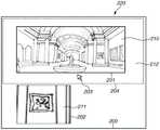
接着,将参考图5来描述指定画面220。图5是示出指定画面220的示例的图。客户端设备140的系统控制单元143控制要在显示单元141处显示的指定画面220。该处理是由第一显示控制单元执行的处理的一个示例。Next, the
指定画面220是显示通过广域照相机110的摄像操作所获取到的第一图像210和通过PTZ照相机120的摄像操作所获取到的第二图像211的画面,并且指定画面220显示在客户端设备140的显示单元141处。此外,用户可以在指定画面220上指定PTZ照相机120的摄像区域。The specified
指定画面220包括显示框200、第一显示区域201、第二显示区域202和可指定区域204。指定画面220的各个部分显示在显示框200内。The
第一显示区域201是指定画面220中的与广域照相机110的摄像区域相对应的区域。将广域照相机110所拍摄的第一图像210显示在第一显示区域201上。由于第一显示区域201是与广域照相机110的摄像区域相对应的区域,因此第一显示区域201的大小与第一图像210的大小相同。The
第二显示区域202是显示PTZ照相机120所拍摄的第二图像211的区域。The
光标203是用户操作以在显示单元141处指定任意点或任意范围的对象。The
可指定区域204是指定画面220中的表示PTZ照相机120的可摄像区域160和162的区域。当用户指定了可指定区域204中的区域时,设置PTZ照相机120的平摇角度、俯仰角度和变焦量,使得PTZ照相机120可以对与用户所指定的区域(指定区域)相对应的摄像区域进行摄像。因此,改变PTZ照相机120的摄像方向和视角。第一图像210显示在可指定区域204中的与广域照相机110的摄像区域161和163相对应的位置处。第一图像210包括在可指定区域204中并与可指定区域204重叠。将与可指定区域204中的第一图像210的区域不同的区域(即,第一图像210外侧的区域)称为外侧区域212。可指定区域204是第二画面区域的示例。The
在本典型实施例中,用户使用输入单元142来操作光标203,并通过在可指定区域204内指定任意点或任意范围来指定可指定区域204内的区域,使得可以改变PTZ照相机120的摄像方向和视角。此时,基于来自输入单元142的输出,客户端设备140的系统控制单元143接受可指定区域204中的用户所指定的区域。In the present exemplary embodiment, the user operates the
在指定画面220中,可指定区域204包括显示第一图像210的第一显示区域201外侧的区域。在本典型实施例中,可指定区域204包括整个第一显示区域201。然后,外侧区域212在第一显示区域201的整个周围中与第一显示区域201邻接。外侧区域212显示为空白空间。In the
例如,摄像设备100的系统控制单元124将广域照相机110所拍摄的第一图像210和PTZ照相机120所拍摄的第二图像211定期发送到客户端设备140。客户端设备140的系统控制单元143使用从摄像设备100接收到的第一图像210和第二图像211来更新指定画面220中的第一图像210和第二图像211。For example, the
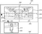
接着,将参考图6来描述通过使用指定画面220来设置PTZ照相机120的摄像方向和视角的方法。图6是示出指定画面220的示例的图。如图6所示,将包括分别与PTZ照相机120的平摇方向和俯仰方向相对应的水平方向轴205和垂直方向轴206的坐标设置到可指定区域204。用户操作光标203以指定这些坐标中的任意点。水平方向轴205和垂直方向轴206可以是或可以不是实际显示在指定画面220中的。Next, a method of setting the imaging direction and the angle of view of the
在本典型实施例中,在可指定区域204中,水平方向轴205延伸的方向的中央对应于0°的平摇角度,其左端对应于-90°的平摇角度,以及其右端对应于90°的平摇角度。此外,在可指定区域204中,垂直方向轴206延伸的方向的中央对应于30°的俯仰角度,其上端对应于0°的俯仰角度,以及其下端对应于60°的俯仰角度。在本典型实施例中,平摇角度和俯仰角度在可指定区域204中线性地改变。然而,该结构不限于此。例如,可以基于广域照相机110的曲率非线性地分配平摇角度和俯仰角度。In the present exemplary embodiment, in the
如图6所示,用户操作输入单元142以指定范围指定开始点207a和范围指定结束点207b,从而指定在对角线上具有这两个点207a和207b的矩形区域(要指定的区域)。指定区域与PTZ照相机120的新摄像区域相对应。由用户执行的要指定的区域的指定与用于改变PTZ照相机120的摄像区域的指示相对应。在图6的示例中,指定区域包括第一图像210的一部分和与第一图像210邻接的外侧区域212的一部分。指定区域是第一画面区域的示例。指定区域可以是仅包括外侧区域212的一部分的区域,或者可以是仅包括第一图像210的一部分的区域。As shown in FIG. 6 , the user operates the
通过基于输入单元142的输出来接受范围指定开始点207a和范围指定结束点207b,客户端设备140的系统控制单元143接受在对角线上具有这两个点207a和207b的矩形指定区域。By accepting the range
然后,为了通过PTZ照相机120来对与指定区域相对应的摄像区域进行摄像,系统控制单元143基于所接受的范围指定开始点207a和范围指定结束点207b来计算PTZ照相机120的摄像方向和视角。将与以上所计算出的PTZ照相机120的摄像方向和视角有关的信息称为摄像区域信息。Then, in order to image the imaging area corresponding to the designated area by the
然后,系统控制单元143将摄像区域信息发送到摄像设备100。基于从客户端设备140发送来的摄像区域信息,摄像设备100的系统控制单元124通过下面描述的摄像区域设置处理来改变PTZ照相机120的摄像方向和视角。更具体地,基于摄像区域信息,系统控制单元124经由驱动控制单元126来驱动变焦马达127、平摇马达128和俯仰马达129。Then, the
接着,将参考图7来描述摄像区域设置处理。图7是示出摄像区域设置处理的示例的流程图。摄像区域设置处理由摄像设备100的系统控制单元124执行。特别地,摄像区域设置处理是用于设置PTZ照相机120的摄像方向和视角的处理。图7中的处理是由摄像控制单元执行的处理的一个示例。Next, the imaging area setting process will be described with reference to FIG. 7 . FIG. 7 is a flowchart showing an example of imaging area setting processing. The imaging area setting process is performed by the
在步骤S301中,基于客户端设备140和摄像设备100所执行的通信,系统控制单元124判断用户是否经由客户端设备140的输入单元142输入了用于改变PTZ照相机120的摄像区域的指示。如果系统控制单元124判断为用户输入了用于改变PTZ照相机120的摄像区域的指示(步骤S301中为“是”),则处理进入步骤S302。如果系统控制单元124判断为用户没有输入该指示(步骤S301中为“否”),则图7中的处理结束。In step S301 , based on the communication performed by the
在步骤S302中,系统控制单元124从客户端设备140接收摄像区域信息。如上所述,摄像区域信息是与客户端设备140所计算出的PTZ照相机120的摄像方向和视角有关的信息。In step S302 , the
在步骤S303中,系统控制单元124判断步骤S302中所接收到的摄像区域信息中所包括的视角是否落入PTZ照相机120的最大视角的范围内。如果系统控制单元124判断为摄像区域信息中所包括的视角落入PTZ照相机120的最大视角的范围内(步骤S303中为“是”),则处理进入步骤S305。如果系统控制单元124判断为摄像区域信息中所包括的视角没有落入PTZ照相机120的最大视角的范围内(步骤S303中为“否”),则处理进入步骤S304。In step S303 , the
在步骤S304中,系统控制单元124将步骤S302中所接收到的摄像区域信息中所包括的视角校正为PTZ照相机120的最大视角。然而,系统控制单元124可以将步骤S302中所接收到的摄像区域信息中所包括的视角校正为小于PTZ照相机120的最大视角的角度。In step S304 , the
在步骤S305中,基于摄像区域信息,系统控制单元124经由驱动控制单元126来驱动变焦马达127、平摇马达128和俯仰马达129。通过上述处理,系统控制单元124将PTZ照相机120的摄像方向和视角控制为用户所指定的摄像方向和视角。然后,系统控制单元124控制PTZ照相机120,以对与指定画面220处所指定的区域相对应的摄像区域进行摄像,从而获取第二图像211。如果在步骤S304中执行了校正,则系统控制单元124控制PTZ照相机120c,从而以校正后的视角拍摄与在指定画面220处所指定的区域相对应的摄像方向上的图像,由此获取第二图像211。In step S305 , based on the imaging area information, the
客户端设备140的系统控制单元143从摄像设备100的系统控制单元124定期接收第二图像211,以在指定画面220上显示第二图像211。用于显示第二图像211的处理是由第二显示控制单元执行的处理的一个示例。The
如上所述,在指定画面220处,用户可以指定要指定为包括外侧区域212的一部分的区域。然后,客户端设备140在指定画面220上显示通过PTZ照相机120对与指定区域相对应的摄像区域进行摄像所获取到的第二图像211。因此,用户可以直观地指定未包括在与第一图像210相对应的摄像区域中的摄像区域。然后,用户可以容易地显示通过对广域照相机110的摄像区域161和163的范围外侧的区域进行摄像而所获取到的第二图像211。此外,在根据本典型实施例的摄像系统中,如图6所示,可以通过PTZ照相机120对位于广域照相机110的摄像区域的边界上的被摄体整体进行摄像,并显示整个被摄体,从而提高了用户的可用性。As described above, at the
<变形例><Variation>
在上述典型实施例中,图6中的外侧区域212在指定画面220中被显示为空白空间。然而,例如,客户端设备140的系统控制单元143可以着色并显示外侧区域212以与第一图像210区分开。In the above-described exemplary embodiment, the
此外,系统控制单元143可以在外侧区域212中显示过去由PTZ照相机120拍摄并获取到的与外侧区域212相对应的摄像区域的图像。在这种情况下,摄像设备100在启动时使PTZ照相机120拍摄与外侧区域212相对应的图像,并将拍摄图像发送到客户端设备140。客户端设备140在外侧区域212对从摄像设备100接收到的图像进行合成并显示。此后,每当摄像设备100对与外侧区域212相对应的摄像区域进行摄像时,客户端设备140通过使用经由摄像操作所获取到的图像来更新外侧区域212中所显示的图像。系统控制单元143可以仅在外侧区域212的一部分中显示过去由PTZ照相机120拍摄并获取到的图像。外侧区域212中所显示的图像是第三图像的示例。In addition, the
此外,系统控制单元143可以对第一显示区域201中所显示的第一图像210和外侧区域212中所显示的图像执行不同的图像处理。此外,可指定区域204的内侧和外侧之间的边界线可以用如图5或6所示的虚线表示,或者可以用实线表示。此外,代替显示可指定区域204的内侧和外侧之间的边界线,可以使用任意图像来区分可指定区域204的内侧和外侧。Also, the
此外,在上述典型实施例中,如参考图6所述,用户指定范围指定开始点207a和范围指定结束点207b。这里,在用户指定了范围指定开始点207a的情况下,系统控制单元143可以在指定画面220上显示下面描述的参考区域。该参考区域是使范围指定开始点207a作为顶点的矩形区域,并且是PTZ照相机120能够以最大视角对与该参考区域相对应的摄像区域进行摄像的区域。由于PTZ照相机120可以对与参考区域中所包括的区域相对应的摄像区域进行摄像,因此用户可以在指定画面220处容易地指定要由PTZ照相机120进行摄像的区域。该参考区域是第三画面区域的示例。Furthermore, in the above-described exemplary embodiment, as described with reference to FIG. 6, the user specifies the range specifying
此外,在上述典型实施例中,预先确定PTZ照相机120的平摇角度和俯仰角度的范围。然而,可以通过在摄像设备100的初始设置时执行校准来调整PTZ照相机120的平摇角度和俯仰角度的范围。Furthermore, in the above-described exemplary embodiment, the ranges of the pan angle and the tilt angle of the
此外,在上述典型实施例中,在图7的步骤S303和S304中,通过摄像设备100的系统控制单元124来执行与摄像区域信息中所包括的视角是否落入PTZ照相机120的最大视角的范围内有关的判断以及对摄像区域信息的校正。然而,可以通过客户端设备140的系统控制单元143来执行与摄像区域信息中所包括的视角是否落入PTZ照相机120的最大视角的范围内有关的判断以及对摄像区域信息的校正。在这种情况下,系统控制单元143将校正后的摄像区域信息发送到摄像设备100,并且摄像设备100基于所接收到的摄像区域信息来执行用于改变PTZ照相机120的摄像方向和视角的控制。In addition, in the above-described exemplary embodiment, in steps S303 and S304 of FIG. 7 , the
在用户在指定画面220处指定的范围表示超过PTZ照相机120的最大视角的视角的情况下,客户端设备140的系统控制单元143可以在显示单元141处显示错误消息。然后,在这种情况下,系统控制单元143可以执行不接受用户指定的区域的控制。The
在上述典型实施例中,如图5和6所示,整个第一图像210与可指定区域204重叠。然而,如果广域照相机110的摄像区域161和163与PTZ照相机120的可摄像区域160和162部分重叠,则第一图像210的一部分相应地与可指定区域204重叠。In the above-described exemplary embodiment, as shown in FIGS. 5 and 6 , the entire
此外,代替使用PTZ照相机120,摄像设备100可以使用能够仅改变摄像方向和视角中的一个的照相机。Furthermore, instead of using the
<其它典型实施例><Other typical embodiments>
本发明可以以如下方式实现:将用于实现根据上述典型实施例的一个或多个功能的程序经由网络或存储介质提供给系统或设备,并且系统或设备中的计算机的一个或多个处理器读取并执行该程序。此外,还可以利用实现一个或多个功能的电路(例如,专用集成电路(ASIC))来实现本发明。The present invention can be implemented in the following manner: a program for implementing one or more functions according to the above-described exemplary embodiments is provided to a system or device via a network or a storage medium, and one or more processors of a computer in the system or device Read and execute the program. Furthermore, the present invention may also be implemented using circuits (eg, application specific integrated circuits (ASICs)) that implement one or more functions.
尽管已经说明了本发明的典型实施例,但上述典型实施例仅仅是实现本发明的示例,并且不应当被解释为限制本发明的技术范围。换句话说,在不脱离本发明的技术精神或主要特征的情况下,可以以各种方式实现本发明。Although the exemplary embodiments of the present invention have been described, the above-described exemplary embodiments are merely examples for implementing the present invention, and should not be construed as limiting the technical scope of the present invention. In other words, the present invention can be implemented in various ways without departing from the technical spirit or main characteristics of the present invention.
例如,可以提供多个CPU作为摄像设备100或客户端设备140的硬件结构,并且多个CPU可以基于存储在各设备的HDD中的程序来执行处理。此外,代替CPU,图形处理单元(GPU)可以用作摄像设备100或客户端设备140的硬件结构。For example, multiple CPUs may be provided as the hardware configuration of the
如上所述,根据上述典型实施例,可以容易地显示通过对期望的摄像区域进行摄像所获取到的图像。As described above, according to the above-described exemplary embodiments, an image acquired by imaging a desired imaging area can be easily displayed.
其它实施例Other embodiments
本发明的实施例还可以通过如下的方法来实现,即,通过网络或者各种存储介质将执行上述实施例的功能的软件(程序)提供给系统或装置,该系统或装置的计算机或是中央处理单元(CPU)、微处理单元(MPU)读出并执行程序的方法。The embodiments of the present invention can also be implemented by the following method, that is, providing software (programs) for performing the functions of the above-mentioned embodiments to a system or device through a network or various storage media, and the computer of the system or device or the central A method in which a processing unit (CPU) and a microprocessing unit (MPU) read and execute programs.
尽管已经参考典型实施例说明了本发明,但是应该理解,本发明不局限于所公开的典型实施例。所附权利要求书的范围符合最宽的解释,以包含所有这类修改、等同结构和功能。While the present invention has been described with reference to exemplary embodiments, it is to be understood that the invention is not limited to the disclosed exemplary embodiments. The scope of the appended claims is to be accorded the broadest interpretation so as to encompass all such modifications and equivalent structures and functions.
Claims (16)
Translated fromChineseApplications Claiming Priority (2)
| Application Number | Priority Date | Filing Date | Title |
|---|---|---|---|
| JP2018072231AJP7150456B2 (en) | 2018-04-04 | 2018-04-04 | IMAGING SYSTEM, INFORMATION PROCESSING DEVICE, CONTROL METHOD OF INFORMATION PROCESSING DEVICE, AND PROGRAM |
| JP2018-072231 | 2018-04-04 |
Publications (2)
| Publication Number | Publication Date |
|---|---|
| CN110351475A CN110351475A (en) | 2019-10-18 |
| CN110351475Btrue CN110351475B (en) | 2022-05-10 |
Family
ID=68097522
Family Applications (1)
| Application Number | Title | Priority Date | Filing Date |
|---|---|---|---|
| CN201910265973.0AActiveCN110351475B (en) | 2018-04-04 | 2019-04-03 | Image pickup system, information processing apparatus, control method therefor, and storage medium |
Country Status (3)
| Country | Link |
|---|---|
| US (1) | US11184549B2 (en) |
| JP (1) | JP7150456B2 (en) |
| CN (1) | CN110351475B (en) |
Families Citing this family (5)
| Publication number | Priority date | Publication date | Assignee | Title |
|---|---|---|---|---|
| KR102619271B1 (en)* | 2018-11-01 | 2023-12-28 | 한화비전 주식회사 | Video capturing device including plurality of cameras and video capturing system including the same |
| KR102743278B1 (en)* | 2019-11-21 | 2024-12-17 | 삼성전자 주식회사 | Electronic device including tilt ois and method for image shooting and processing by the same |
| WO2022040734A1 (en)* | 2020-08-24 | 2022-03-03 | Axiiio Pty Ltd | "remote camera operation" |
| JP2023046874A (en)* | 2021-09-24 | 2023-04-05 | キヤノン株式会社 | IMAGING DEVICE, IMAGING DEVICE CONTROL METHOD AND PROGRAM |
| EP4270940B1 (en)* | 2022-04-26 | 2024-10-30 | Axis AB | Ptz masking control |
Family Cites Families (16)
| Publication number | Priority date | Publication date | Assignee | Title |
|---|---|---|---|---|
| JP2006128932A (en) | 2004-10-27 | 2006-05-18 | Suekage Sangyo Co Ltd | Imaging device, imaging system, imaging device control method, and imaging device control program |
| JP2006191411A (en)* | 2005-01-07 | 2006-07-20 | Canon Inc | Camera control device, image display device, camera control method, image display method, and program |
| IL189251A0 (en)* | 2008-02-05 | 2008-11-03 | Ehud Gal | A manned mobile platforms interactive virtual window vision system |
| CN102577347B (en) | 2009-06-29 | 2015-09-23 | 博世安防系统有限公司 | All-around intelligent makes an inspection tour the spherical surveillance camera system and method with Situation Awareness automatically |
| WO2011032117A1 (en)* | 2009-09-13 | 2011-03-17 | Delacom Detection Systems, Llc | Method and system for wildfire detection using a visible range camera |
| JP2013062559A (en)* | 2010-09-02 | 2013-04-04 | Dodwell Bms Ltd | Imaging monitor screen and omnidirectional imaging screen monitoring system |
| JP2014175706A (en)* | 2013-03-06 | 2014-09-22 | Sumitomo Electric Ind Ltd | Monitor device, monitor method, and imaging unit arrangement method |
| JP2015035686A (en)* | 2013-08-08 | 2015-02-19 | 住友電気工業株式会社 | Camera device, monitoring system, control device, and control program |
| JP6281933B2 (en)* | 2013-09-13 | 2018-02-21 | 株式会社ドッドウエル ビー・エム・エス | Video display device and video display method |
| JP2015141471A (en) | 2014-01-27 | 2015-08-03 | キヤノン株式会社 | Information processing apparatus and information processing apparatus control method |
| JP2016096481A (en)* | 2014-11-14 | 2016-05-26 | キヤノン株式会社 | Control apparatus, photographing system, control method, and program |
| US10291842B2 (en) | 2015-06-23 | 2019-05-14 | Samsung Electronics Co., Ltd. | Digital photographing apparatus and method of operating the same |
| KR20170006559A (en) | 2015-07-08 | 2017-01-18 | 엘지전자 주식회사 | Mobile terminal and method for controlling the same |
| US10764539B2 (en)* | 2016-03-22 | 2020-09-01 | Sensormatic Electronics, LLC | System and method for using mobile device of zone and correlated motion detection |
| KR102593824B1 (en)* | 2016-08-31 | 2023-10-25 | 삼성전자주식회사 | Method for controlling a camera and electronic device thereof |
| CN107025694B (en) | 2017-05-24 | 2019-06-21 | 厦门天诚创智能科技有限公司 | A kind of intelligent patrol detection device for community's night security protection |
- 2018
- 2018-04-04JPJP2018072231Apatent/JP7150456B2/enactiveActive
- 2019
- 2019-03-29USUS16/370,081patent/US11184549B2/enactiveActive
- 2019-04-03CNCN201910265973.0Apatent/CN110351475B/enactiveActive
Also Published As
| Publication number | Publication date |
|---|---|
| US11184549B2 (en) | 2021-11-23 |
| JP7150456B2 (en) | 2022-10-11 |
| JP2019186635A (en) | 2019-10-24 |
| CN110351475A (en) | 2019-10-18 |
| US20190313030A1 (en) | 2019-10-10 |
Similar Documents
| Publication | Publication Date | Title |
|---|---|---|
| CN110351475B (en) | Image pickup system, information processing apparatus, control method therefor, and storage medium | |
| CN102202168B (en) | Controls, camera systems and programs | |
| KR101662074B1 (en) | Control device, camera system, and recording medium | |
| CN110022431A (en) | Image pickup apparatus, image pickup method, display apparatus, and display method | |
| JP2008311804A (en) | Imaging apparatus and method | |
| US9961268B2 (en) | Control device, imaging system, control method, and program for controlling imaging unit according to image capturing direction and zoom magnification | |
| JP6478777B2 (en) | Control device, control method therefor, and program | |
| JPH118845A (en) | Panoramic image generation device and its method | |
| US11184547B2 (en) | Imaging device, method for controlling imaging device, and recording medium | |
| US11637958B2 (en) | Control apparatus, control method, and storage medium | |
| JP2005167397A (en) | Server apparatus, control method thereof, and storage medium | |
| KR102707798B1 (en) | Camera device capable of pan-tilt-zoom operation and video surveillance system and method using the same | |
| JP2016096482A (en) | Image processing apparatus, image processing method, and program | |
| JP2006115091A (en) | Imaging device | |
| JP7515265B2 (en) | Image capture device, image processing device control method, and image capture system | |
| JP6702675B2 (en) | IMAGING DEVICE, IMAGING DEVICE CONTROL METHOD, AND PROGRAM | |
| JP2019140566A (en) | Information processing apparatus, information processing method, and program | |
| JP2013012848A (en) | Camera device and control method therefor | |
| JP2019140599A (en) | Information processing apparatus, information processing method, and program | |
| US20220053130A1 (en) | Multifunctional camera | |
| US20230410258A1 (en) | Image capturing apparatus, image capturing system, method, and non-transitory computer readable storage medium | |
| JP2023016580A (en) | Imaging system, imaging method, and computer program | |
| JP2024175919A (en) | Information processing device, control method for information processing device, program, and imaging system | |
| JP2025062281A (en) | Imaging system and imaging method | |
| JP2025132446A (en) | Imaging device, control method, and computer program |
Legal Events
| Date | Code | Title | Description |
|---|---|---|---|
| PB01 | Publication | ||
| PB01 | Publication | ||
| SE01 | Entry into force of request for substantive examination | ||
| SE01 | Entry into force of request for substantive examination | ||
| GR01 | Patent grant | ||
| GR01 | Patent grant |