CN110344810B - Method for establishing horizontal cavity of rock salt layer gas storage - Google Patents
Method for establishing horizontal cavity of rock salt layer gas storageDownload PDFInfo
- Publication number
- CN110344810B CN110344810BCN201910647951.0ACN201910647951ACN110344810BCN 110344810 BCN110344810 BCN 110344810BCN 201910647951 ACN201910647951 ACN 201910647951ACN 110344810 BCN110344810 BCN 110344810B
- Authority
- CN
- China
- Prior art keywords
- cavity
- salt rock
- rock layer
- partial
- current
- Prior art date
- Legal status (The legal status is an assumption and is not a legal conclusion. Google has not performed a legal analysis and makes no representation as to the accuracy of the status listed.)
- Active
Links
- 238000000034methodMethods0.000titleclaimsabstractdescription68
- 235000002639sodium chlorideNutrition0.000titleabstract6
- FAPWRFPIFSIZLT-UHFFFAOYSA-MSodium chlorideChemical compound[Na+].[Cl-]FAPWRFPIFSIZLT-UHFFFAOYSA-M0.000titleabstract3
- 239000011780sodium chlorideSubstances0.000titleabstract3
- 150000003839saltsChemical class0.000claimsabstractdescription103
- 239000011435rockSubstances0.000claimsabstractdescription101
- 238000004090dissolutionMethods0.000claimsabstractdescription96
- XLYOFNOQVPJJNP-UHFFFAOYSA-NwaterSubstancesOXLYOFNOQVPJJNP-UHFFFAOYSA-N0.000claimsabstractdescription22
- 230000015572biosynthetic processEffects0.000claimsabstractdescription8
- 238000001514detection methodMethods0.000claimsdescription14
- 238000010276constructionMethods0.000claimsdescription6
- 238000005553drillingMethods0.000claimsdescription6
- 230000000694effectsEffects0.000abstractdescription4
- 239000010410layerSubstances0.000description60
- 239000000243solutionSubstances0.000description60
- 238000005516engineering processMethods0.000description10
- 239000012267brineSubstances0.000description5
- HPALAKNZSZLMCH-UHFFFAOYSA-Msodium;chloride;hydrateChemical compoundO.[Na+].[Cl-]HPALAKNZSZLMCH-UHFFFAOYSA-M0.000description5
- 238000002347injectionMethods0.000description3
- 239000007924injectionSubstances0.000description3
- 238000005259measurementMethods0.000description3
- 238000012986modificationMethods0.000description3
- 230000004048modificationEffects0.000description3
- 238000011156evaluationMethods0.000description2
- 239000012535impuritySubstances0.000description2
- 239000011229interlayerSubstances0.000description2
- 230000007547defectEffects0.000description1
- 230000007812deficiencyEffects0.000description1
- 238000010586diagramMethods0.000description1
- 238000011056performance testMethods0.000description1
- 239000000126substanceSubstances0.000description1
Images


Classifications
- E—FIXED CONSTRUCTIONS
- E21—EARTH OR ROCK DRILLING; MINING
- E21B—EARTH OR ROCK DRILLING; OBTAINING OIL, GAS, WATER, SOLUBLE OR MELTABLE MATERIALS OR A SLURRY OF MINERALS FROM WELLS
- E21B43/00—Methods or apparatus for obtaining oil, gas, water, soluble or meltable materials or a slurry of minerals from wells
- E21B43/28—Dissolving minerals other than hydrocarbons, e.g. by an alkaline or acid leaching agent
- E—FIXED CONSTRUCTIONS
- E21—EARTH OR ROCK DRILLING; MINING
- E21F—SAFETY DEVICES, TRANSPORT, FILLING-UP, RESCUE, VENTILATION, OR DRAINING IN OR OF MINES OR TUNNELS
- E21F17/00—Methods or devices for use in mines or tunnels, not covered elsewhere
- E21F17/16—Modification of mine passages or chambers for storage purposes, especially for liquids or gases
Landscapes
- Engineering & Computer Science (AREA)
- Mining & Mineral Resources (AREA)
- Life Sciences & Earth Sciences (AREA)
- Geology (AREA)
- General Life Sciences & Earth Sciences (AREA)
- Geochemistry & Mineralogy (AREA)
- Physics & Mathematics (AREA)
- Environmental & Geological Engineering (AREA)
- Fluid Mechanics (AREA)
- Geophysics And Detection Of Objects (AREA)
Abstract
Description
Translated fromChinese技术领域technical field
本申请涉及盐岩层储气库建库领域,尤其涉及一种盐岩层储气库水平腔的建立方法。The application relates to the field of building a gas storage in a salt rock layer, in particular to a method for establishing a horizontal cavity of a gas storage layer in a salt rock layer.
背景技术Background technique
中国适合建储气库的盐岩地层多以层状地质构造为主,层状地质构造的盐岩地层地质结构复杂、盐岩杂质含量高、分布不均匀,且沉积盆地中心以外的地区往往有一定的倾斜角使得层状地质为倾斜夹层。倾斜夹层以及杂质分布不均容易导致采用熔盐发建立储气库时存在偏溶现象,进而使得得到的储气库腔体偏向一个方向,导致畸形腔的发生,尤其是竖直腔的畸形情况非常明显,存在概率非常高。The salt rock strata suitable for UGS construction in China are mostly layered geological structures. The salt rock strata of layered geological structures have complex geological structure, high content of salt rock impurities and uneven distribution, and areas outside the center of sedimentary basins often have A certain inclination angle makes the layered geology an inclined interlayer. Inclined interlayers and uneven distribution of impurities can easily lead to partial dissolution when molten salt is used to build gas storage, which in turn causes the obtained gas storage cavity to deviate in one direction, resulting in the occurrence of deformed cavities, especially the deformity of vertical cavities. It is very obvious that the probability of existence is very high.
现有技术中,本领域技术人员可知的是,在层状盐岩中建库,实际上最适合是水平腔,而水平腔通常采用对井造腔技术实施。In the prior art, those skilled in the art know that, in fact, the most suitable horizontal cavity is to build a reservoir in a layered salt rock, and the horizontal cavity is usually implemented by the well-to-well cavity construction technology.
本申请人在实施现有技术的对井造腔技术时,发现其存在以下缺陷和不足:When the applicant implements the prior art cavity-making technology for wells, it is found that it has the following defects and deficiencies:
1.现有的对井造腔技术在实施的时候,由于水平段过长(一般300m以上),超出了声呐检测装置的探测范围(探测范围一般小于100m),因此,水平腔的中间段的形状往往无法获取,进而无法对腔体的稳定性进行评判;1. When the existing cavity-making technology is implemented, the horizontal section is too long (generally more than 300m), which exceeds the detection range of the sonar detection device (the detection range is generally less than 100m). The shape is often unavailable, and the stability of the cavity cannot be judged;
2.现有的对井造腔技术在实施时,由于水平段距离过长存在水平腔的中间的顶部不可控,进而最终形成的水平腔易存在两端大、中间小的现象,这一现象的存在降低了盐岩资源利用率;2. During the implementation of the existing cavity-making technology for wells, because the distance between the horizontal sections is too long, the top of the middle of the horizontal cavity is uncontrollable, and the final formed horizontal cavity is prone to the phenomenon that the two ends are large and the middle is small. This phenomenon The existence of salt rock reduces the utilization rate of salt rock resources;
3.现有的对井造腔技术在实施时,随着水平段距离的增大,卤水浓度随着增大,浓度越大的卤水越难溶解地层盐岩,因此使得能够得到的水平腔的长度受到限制。3. During the implementation of the existing well cavity-making technology, with the increase of the distance of the horizontal section, the brine concentration increases, and the brine with the higher concentration is more difficult to dissolve the formation salt rock, thus making it possible to obtain the horizontal cavity. Length is limited.
申请内容Application content
本申请实施例通过提供一种盐岩层储气库水平腔的建立方法,用以实现在盐岩层建立可以有效评判其稳定性、形状可控、长度可以根据需要进行设置的水平腔。The embodiments of the present application provide a method for establishing a horizontal cavity of a gas storage in a salt rock layer, so as to realize the establishment of a horizontal cavity in the salt rock layer whose stability can be effectively judged, the shape is controllable, and the length can be set as required.
为了解决上述问题,本申请实施例提供了一种盐岩层储气库水平腔的建立方法,其中,所述建立方法包括:根据所述盐岩层的偏溶特性设置N个直井,其中N为大于等于2的正整数,其中:所述偏溶特性包括偏溶方向和偏溶距离;各所述直井沿所述偏溶方向依次排布,且任意两相邻所述直井位于一所述偏溶距离两端附近,使得任意两相邻所述直井之间可自然溶通;两相邻所述直井之间自然溶通后水溶造腔形成所述水平腔。In order to solve the above problems, an embodiment of the present application provides a method for establishing a horizontal cavity of a gas storage in a salt rock layer, wherein the establishing method includes: setting N vertical wells according to the partial solution characteristics of the salt rock layer, where N is greater than A positive integer equal to 2, wherein: the partial solution characteristic includes the partial solution direction and the partial solution distance; the vertical wells are arranged in sequence along the partial solution direction, and any two adjacent vertical wells are located in one of the partial solution The distance is near the two ends, so that any two adjacent vertical wells can be naturally dissolved; the horizontal cavity is formed after the natural dissolution between two adjacent vertical wells.
如上所述的盐岩层储气库水平腔的建立方法,其中,优选的,所述根据所述盐岩层的偏溶特性设置多个直井,具体包括:在所述盐岩层的偏溶特性未知的情况下,依次设置直井。The method for establishing a horizontal cavity of a gas storage in a salt rock layer as described above, wherein, preferably, the setting of a plurality of vertical wells according to the partial solution characteristics of the salt rock layer specifically includes: when the partial dissolution characteristics of the salt rock layer are unknown In this case, set up vertical wells in sequence.
如上所述的盐岩层储气库水平腔的建立方法,其中,优选的,在所述盐岩层的偏溶特性未知的情况下,依次设置直井,具体包括:在盐岩层所在位置的地表面上选定一位置作为当前预设位置;在所述当前预设位置处设置直井作为当前直井,并获得当前直井的当前偏溶腔体;测量所述当前偏溶腔体的偏溶特性;根据当前直井的偏溶腔体的偏溶特性选定另一位置作为新的当前预预设位置;在新的所述当前预设位置处设置直井作为新的当前直井。The above-mentioned method for establishing a horizontal cavity of a gas storage in a salt rock layer, wherein, preferably, when the partial dissolution characteristics of the salt rock layer are unknown, the vertical wells are arranged in sequence, which specifically includes: on the ground surface where the salt rock layer is located Select a position as the current preset position; set the vertical well at the current preset position as the current vertical well, and obtain the current partial solution cavity of the current vertical well; measure the partial solution characteristics of the current partial solution cavity; The partial solution property of the partial solution cavity of the vertical well selects another position as the new current preset position; the vertical well is set at the new current preset position as the new current vertical well.
如上所述的盐岩层储气库水平腔的建立方法,其中,优选的,在所述当前预设位置处设置直井作为当前直井,并获得当前直井的当前偏溶腔体,具体包括:在所述当前预设位置处钻井至目标盐岩层;在所述目标盐岩层水溶建腔得到当前偏溶腔体。The above-mentioned method for establishing a horizontal cavity of a gas storage in a salt rock layer, wherein, preferably, a vertical well is set at the current preset position as the current vertical well, and the current partial solution cavity of the current vertical well is obtained, which specifically includes: Drilling to the target salt rock layer at the current preset position; building a cavity in water solution in the target salt rock layer to obtain the current partial solution cavity.
如上所述的盐岩层储气库水平腔的建立方法,其中,优选的,在所述目标盐岩层水溶建腔得到当前偏溶腔体,具体包括:在所述目标盐岩层水溶建腔至第一预设体积得到当前偏溶腔体;或,在所述目标盐岩层水溶建腔得到过程腔,待所述过程腔与相邻的前一个所述过程腔自然贯通之后,循环造腔至第一预设体积得到当前偏溶腔体。The method for establishing a horizontal cavity of a gas storage in a salt rock layer as described above, wherein, preferably, obtaining the current partial solution cavity in the target salt rock layer water-solubilized cavity building specifically includes: building a water-soluble cavity in the target salt rock layer to the first A preset volume is used to obtain the current partial solution cavity; or, a process cavity is obtained in the target salt rock formation water-dissolved cavity, and after the process cavity and the adjacent previous process cavity are naturally connected, the cavity is constructed in a cycle to the first process cavity. A preset volume is used to obtain the current partial solution cavity.
如上所述的盐岩层储气库水平腔的建立方法,其中,优选的,在所述目标盐岩层水溶建腔,具体包括:采用油垫法水溶建腔或气垫法水溶建腔。The above-mentioned method for establishing a horizontal cavity of a gas storage in a salt rock layer, wherein, preferably, building a cavity in water solution in the target salt rock layer specifically includes: building a cavity in water solution by oil cushion method or building a cavity in water solution by air cushion method.
如上所述的盐岩层储气库水平腔的建立方法,其中,优选的,所述测量所述当前偏溶腔体的偏溶特性,具体包括:采用声呐检测装置检测所述当前偏溶腔体的偏溶特性;其中:所述声呐检测装置的检测范围大于所述盐岩层的偏溶距离。The method for establishing a horizontal cavity of a gas storage in a salt rock layer as described above, wherein, preferably, the measuring the partial solution characteristics of the current partial solution cavity specifically includes: using a sonar detection device to detect the current partial solution cavity The partial solution characteristic; wherein: the detection range of the sonar detection device is greater than the partial solution distance of the salt rock layer.
如上所述的盐岩层储气库水平腔的建立方法,其中,优选的,所述两相邻所述直井之间自然溶通后水溶造腔形成所述水平腔,具体包括:在所述目标盐岩层水溶建腔得到过程腔,待所述过程腔与相邻的前一个所述过程腔自然溶通之后,循环水溶造腔至预设水平腔体积得到所述水平腔。The method for establishing a horizontal cavity of a gas storage in a salt rock layer as described above, wherein, preferably, the horizontal cavity is formed by water-dissolving cavity after natural dissolution between the two adjacent vertical wells, specifically comprising: in the target A process cavity is obtained by building a cavity by water dissolving in the salt rock layer, and after the process cavity and the adjacent preceding process cavity are naturally fused, circulating the water dissolving cavity to a preset horizontal cavity volume to obtain the horizontal cavity.
如上所述的盐岩层储气库水平腔的建立方法,其中,优选的,所述根据所述盐岩层的偏溶特性设置N个直井,具体包括:在所述盐岩层的偏溶特性已知的情况下,根据已知所述盐岩层的偏溶特性一次性设置N个直井。The method for establishing a horizontal cavity of a gas storage in a salt rock layer as described above, wherein, preferably, the setting of N vertical wells according to the partial solution property of the salt rock layer specifically includes: the partial solution property of the salt rock layer is known In the case of , N vertical wells are set at one time according to the known partial dissolution characteristics of the salt rock formation.
如上所述的盐岩层储气库水平腔的建立方法,其中,优选的,所述两相邻所述直井之间自然溶通后水溶造腔形成所述水平腔,具体包括:待任意两相邻的所述直井均自然溶通之后,多井对流水溶造腔形成所述水平腔。The above-mentioned method for establishing a horizontal cavity of a gas storage in a salt rock layer, wherein, preferably, the horizontal cavity is formed by water-dissolving cavity after natural dissolution between the two adjacent vertical wells, which specifically includes: waiting for any two phases After the adjacent vertical wells are naturally dissolved, the horizontal cavity is formed by multi-well convection water dissolution cavity.
本申请实施例中具有如下技术效果:There are the following technical effects in the embodiment of the present application:
本申请采用N个直井建立水平腔,其中,N为大于等于2的正整数,各直井根据所述盐岩层的偏溶特性依次排布,所述偏溶特性包括偏溶方向和偏溶距离,偏溶方向确定了依次排布的任意两相邻所述直井的空间方位,各所述直井沿所述偏溶方向依次排布,偏溶距离确定了依次排布的任意两相邻所述直井之间的距离,任意两相邻所述直井位于一所述偏溶距离的两端附近,保证了任意两相邻所述直井之间可自然溶通;两相邻所述直井之间自然溶通之后,水溶造腔形成所述水平腔。The present application uses N vertical wells to establish a horizontal cavity, where N is a positive integer greater than or equal to 2, and the vertical wells are arranged in sequence according to the partial dissolution characteristics of the salt rock layer, and the partial dissolution characteristics include the partial dissolution direction and the partial dissolution distance, The partial solution direction determines the spatial orientation of any two adjacent vertical wells arranged in sequence, each of the vertical wells is arranged in sequence along the partial solution direction, and the partial solution distance determines any two adjacent vertical wells arranged in sequence. The distance between any two adjacent vertical wells is located near the two ends of the partial solution distance, which ensures that any two adjacent vertical wells can be naturally dissolved; the two adjacent vertical wells are naturally dissolved. After passing through, the water-dissolved cavity is formed to form the horizontal cavity.
该过程中,可以通过每一个直井进行水平腔的检测,进行可以有效的评判水平腔的稳定性;同时,任意两相邻直井位于一所述偏溶距离两端附近,使得两相邻直井之间的一段水平腔的长度约等于偏溶距离,该情况下,该段水平腔的形状均匀,不会出现两端大、中间小的情况,提高了盐岩层资源利用率;再者,该水平腔是有多段位于任意两相邻直井之间的一小段水平腔组成的,长度不受限制。In this process, the horizontal cavity can be detected through each vertical well, and the stability of the horizontal cavity can be effectively judged; at the same time, any two adjacent vertical wells are located near the two ends of the eccentric distance, so that the two adjacent vertical wells are The length of a section of horizontal cavity between them is approximately equal to the partial solution distance. In this case, the shape of this section of horizontal cavity is uniform, and there will be no situation where the ends are large and the middle is small, which improves the utilization rate of salt rock resources; The cavity is composed of a small section of horizontal cavity located between any two adjacent vertical wells, and the length is not limited.
上述说明仅是本申请技术方案的概述,为了能够更清楚了解本申请的技术手段,而可依照说明书的内容予以实施,并且为了让本申请的上述和其它目的、特征和优点能够更明显易懂,以下特举本申请的具体实施方式。The above description is only an overview of the technical solution of the present application. In order to be able to understand the technical means of the present application more clearly, it can be implemented according to the content of the description, and in order to make the above-mentioned and other purposes, features and advantages of the present application more obvious and easy to understand , and the specific embodiments of the present application are listed below.
附图说明Description of drawings
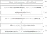
图1为本发明实施例中盐岩层储气库水平腔的建立方法的流程示意图;1 is a schematic flowchart of a method for establishing a horizontal cavity of a gas storage in a salt rock layer according to an embodiment of the present invention;
图2为本发明实施例中依次设置直井来建立盐岩层储气库水平腔方法的流程示意图;2 is a schematic flowchart of a method for setting up vertical wells in sequence to establish a horizontal cavity of a gas storage in a salt rock formation according to an embodiment of the present invention;
图3为本发明实施例中采用一次设置N个直井建立盐岩层储气库水平腔方法的流程示意图。3 is a schematic flowchart of a method for establishing a horizontal cavity of a salt rock gas storage gas storage by setting N vertical wells at a time in an embodiment of the present invention.
具体实施方式Detailed ways
本申请实施例提供了一种盐岩层储气库水平腔的建立方法,用以解决现有技术中对井造腔实施时存在的水平段过长、存在的水平腔体稳定性不方便评判、水平腔体形状不均匀、最终得到的水平腔体的长度受限的技术问题。The embodiment of the present application provides a method for establishing a horizontal cavity of a gas storage in a salt rock layer, which is used to solve the problems of excessively long horizontal section, inconvenient evaluation of the stability of the existing horizontal cavity, The technical problems of the uneven shape of the horizontal cavity and the limited length of the finally obtained horizontal cavity.
下面通过附图以及具体实施例对本申请技术方案做详细的说明,应当理解本申请实施例以及实施例中的具体特征是对本申请技术方案的详细的说明,而不是对本申请技术方案的限定,在不冲突的情况下,本申请实施例以及实施例中的技术特征可以相互组合。The technical solutions of the present application will be described in detail below with reference to the accompanying drawings and specific embodiments. If there is no conflict, the embodiments of the present application and the technical features in the embodiments may be combined with each other.
实施例一Example 1
图1为本发明实施例中的盐岩层储气库水平腔的建立方法示意图,如图1所示,所述方法包括:FIG. 1 is a schematic diagram of a method for establishing a horizontal cavity of a salt rock gas storage in an embodiment of the present invention. As shown in FIG. 1 , the method includes:
步骤110:根据所述盐岩层的偏溶特性设置N个直井,其中N为大于等于2的正整数,其中:所述偏溶特性包括偏溶方向和偏溶距离;Step 110 : setting N vertical wells according to the partial dissolution characteristics of the salt rock layer, where N is a positive integer greater than or equal to 2, wherein: the partial dissolution characteristics include a partial dissolution direction and a partial dissolution distance;
具体而言,直井水溶造腔过程是一个复杂的流体动力学和化学动力学过程,其实质是在卤水浓度差下依靠分子扩散作用实现溶腔,是一种静态盐溶过程。目标溶腔所在盐岩层的偏溶特性决定溶腔工作的效果和效率。具体的,偏溶特性包括偏溶方向和偏溶距离,偏溶方向决定了溶腔形成时的方向,偏溶距离是指沿着盐岩层的偏溶方向的能够实现两腔体自然溶通的距离,决定着任意两相邻溶腔之间的自然溶通效果。根据所述盐岩层的偏溶特性设置N个直井,是指在盐岩层所在位置的地表根据盐岩层的偏溶特性设置直井位置,即预设直井位置,预设直井位置的目的是根据预设位置进行钻井,实现钻进工作的的针对性进行,以确保两相邻溶腔的自然连通。Specifically, the process of water-dissolving cavity formation in vertical wells is a complex hydrodynamic and chemical kinetic process. The partial dissolution characteristics of the salt rock layer where the target cavern is located determines the effect and efficiency of the cavern work. Specifically, the partial dissolution characteristics include the partial dissolution direction and the partial dissolution distance. The partial dissolution direction determines the direction of the formation of the dissolution cavity. The partial dissolution distance refers to the distance along the partial dissolution direction of the salt rock layer that can realize the natural dissolution of the two cavities. The distance determines the natural dissolution effect between any two adjacent cavities. Setting N vertical wells according to the partial dissolution characteristics of the salt rock layer means that the vertical well positions are set on the surface where the salt rock layers are located according to the partial dissolution characteristics of the salt rock layer, that is, preset vertical well positions. Drilling is carried out in different positions, so as to realize the targeted drilling work, so as to ensure the natural connection of two adjacent cavities.
步骤120:各所述直井沿所述偏溶方向依次排布,且任意两相邻所述直井位于一所述偏溶距离两端附近,使得任意两相邻所述直井之间可自然溶通。Step 120: The vertical wells are arranged in sequence along the partial dissolution direction, and any two adjacent vertical wells are located near two ends of the partial dissolution distance, so that any two adjacent vertical wells can be naturally fused .
具体的,当任意两相邻溶腔沿着偏溶方向延伸,且两者之间距离约等于偏溶距离时,该相邻溶腔较易实现自然溶通。Specifically, when any two adjacent dissolution cavities extend along the partial dissolution direction, and the distance between the two is approximately equal to the partial dissolution distance, it is easier for the adjacent dissolution cavities to achieve natural dissolution.
步骤130:两相邻所述直井之间自然溶通后水溶造腔形成所述水平腔。Step 130: The horizontal cavity is formed by water-dissolving cavity after natural dissolution between the two adjacent vertical wells.
具体而言,在盐岩层水溶造腔常用的技术有油垫法水溶建腔或气垫法水溶建腔,考虑到这两种技术均属于现有技术,因此在此不做过多描述。Specifically, the commonly used techniques for water-soluble cavity building in salt rock layers include oil-cushion method and air-cushion method.
本申请采用N个直井建立水平腔,其中,N为大于等于2的正整数,各直井根据所述盐岩层的偏溶特性依次排布,所述偏溶特性包括偏溶方向和偏溶距离,偏溶方向确定了依次排布的任意两相邻所述直井的空间方位,各所述直井沿所述偏溶方向依次排布,偏溶距离确定了依次排布的任意两相邻所述直井之间的距离,任意两相邻所述直井位于一所述偏溶距离的两端附近,保证了任意两相邻所述直井之间可自然溶通;两相邻所述直井之间自然溶通之后,水溶造腔形成所述水平腔。The present application uses N vertical wells to establish a horizontal cavity, where N is a positive integer greater than or equal to 2, and the vertical wells are arranged in sequence according to the partial dissolution characteristics of the salt rock layer, and the partial dissolution characteristics include the partial dissolution direction and the partial dissolution distance, The partial solution direction determines the spatial orientation of any two adjacent vertical wells arranged in sequence, each of the vertical wells is arranged in sequence along the partial solution direction, and the partial solution distance determines any two adjacent vertical wells arranged in sequence. The distance between any two adjacent vertical wells is located near the two ends of the partial solution distance, which ensures that any two adjacent vertical wells can be naturally dissolved; the two adjacent vertical wells are naturally dissolved. After passing through, the water-dissolved cavity is formed to form the horizontal cavity.
该过程中,可以通过每一个直井进行水平腔的检测,进行可以有效的评判水平腔的稳定性;同时,任意两相邻直井位于一所述偏溶距离两端附近,使得两相邻直井之间的一段水平腔的长度约等于偏溶距离,该情况下,该段水平腔的形状均匀,不会出现两端大、中间小的情况,提高了盐岩层资源利用率;再者,该水平腔是有多段位于任意两相邻直井之间的一小段水平腔组成的,长度不受限制,可以根据需要进行设置。In this process, the horizontal cavity can be detected through each vertical well, and the stability of the horizontal cavity can be effectively judged; at the same time, any two adjacent vertical wells are located near the two ends of the eccentric distance, so that the two adjacent vertical wells are The length of a section of horizontal cavity between them is approximately equal to the partial solution distance. In this case, the shape of this section of horizontal cavity is uniform, and there will be no situation where the ends are large and the middle is small, which improves the utilization rate of salt rock resources; The cavity is composed of a small section of horizontal cavity located between any two adjacent vertical wells, the length is not limited, and can be set as required.
实施例二Embodiment 2
基于与前述实施例一中一种盐岩层储气库水平腔的建立方法同样的发明构思,本申请着重考虑了在所述盐岩层的偏溶特性未知的情况下,如何设置N个直井的实施过程,具体的为在所述盐岩层的偏溶特性未知的情况下,依次设置直井。Based on the same inventive concept as the method for establishing a horizontal cavity of a salt rock gas storage in the first embodiment, the present application focuses on the implementation of how to set up N vertical wells when the partial solution properties of the salt rock layer are unknown. The process, specifically, is to set vertical wells in sequence under the condition that the partial solution property of the salt rock layer is unknown.
如图2所示的在在所述盐岩层的偏溶特性未知的情况下,依次设置直井的方法流程示意图,如图2所示,采用依次设置直井建立盐岩层储气库水平腔方法包括:As shown in Fig. 2, when the partial dissolution characteristics of the salt rock layer are unknown, a schematic flow chart of the method for sequentially setting vertical wells is shown. As shown in Fig. 2, the method for establishing a horizontal cavity of a salt rock gas storage gas storage by sequentially setting vertical wells includes:
步骤210:在盐岩层所在位置的地表面上选定一位置作为当前预设位置;Step 210: Select a position on the ground surface where the salt rock layer is located as the current preset position;
具体的,在第一次设置直井位置时,可以人为设置。之后,由于盐岩层的偏溶特性未知,为保证从第二个开始的直井的设置,第n个直井的预设位置需要根据与第n-1个直井的测量结果进行设置。n为大于等于2的正整数。需要说明的是,这里所说的测量结果是指采用声呐检测装置第n-1个直井进行检测得到第n-1个直井的偏溶腔的偏溶方向和偏溶距离,该偏溶方向即盐岩层的偏溶方向,该偏溶距离即盐岩层的偏溶距离。而所采用的声呐检测装置的检测范围大于所述盐岩层的偏溶距离。Specifically, when setting the vertical well position for the first time, it can be set manually. Afterwards, since the partial dissolution characteristics of the salt rock layer are unknown, in order to ensure the setting of vertical wells starting from the second, the preset position of the nth vertical well needs to be set according to the measurement results of the n-1th vertical well. n is a positive integer greater than or equal to 2. It should be noted that the measurement results mentioned here refer to the partial dissolution direction and the partial dissolution distance of the partial dissolution cavity of the n-1 vertical well obtained by the detection of the n-1th vertical well of the sonar detection device. The partial dissolution direction is The partial dissolution direction of the salt rock layer, the partial dissolution distance is the partial dissolution distance of the salt rock layer. The detection range of the adopted sonar detection device is greater than the partial solution distance of the salt rock layer.
步骤220:在所述当前预设位置处设置直井作为当前直井,并获得当前直井的当前偏溶腔体;Step 220: setting the vertical well at the current preset position as the current vertical well, and obtaining the current partial solution cavity of the current vertical well;
具体而言,在当前预设位置处设置直井,即由地面钻井至目标盐岩层,然后采用水溶造腔技术溶腔,水溶造腔技术可以为油垫水溶造腔技术或气垫水溶造腔技术,因此对应的由油垫或气垫控制溶腔的上溶位置,使得水平腔在目标盐岩层内发展,获得偏溶腔体。Specifically, set up a vertical well at the current preset position, that is, drill from the ground to the target salt rock layer, and then use the water-soluble cavity-making technology to dissolve the cavity. Therefore, the up-dissolution position of the dissolution cavity is controlled by the oil cushion or the air cushion correspondingly, so that the horizontal cavity develops in the target salt rock layer, and the partial dissolution cavity is obtained.
需要说明的是,设置第一个直井时,一直采用水溶造腔技术造腔直至第一个直井的偏溶腔体的体积达到了第一预设体积,获得第一个偏溶腔体。设置第n个直井时,先采用水溶造腔技术使得第n个直井在造腔过程中的过程腔与第n-1个直井的偏溶腔体自然溶通,之后,在通过第n个直井和第n-1个直井两者中的任一个进水、另一个出水的循环造腔技术实现第n个直井的偏溶腔体以及第n个直井与第n-1个直井之间的水平腔的建立。第n个直井的偏溶腔体要达到第一预设体积,第n个直井与第n-1个直井之间的水平腔要达到第二预设体积。It should be noted that, when setting up the first vertical well, the water-soluble cavity building technique is used to build the cavity until the volume of the partial solution cavity of the first vertical well reaches the first preset volume, and the first partial solution cavity is obtained. When setting up the nth vertical well, the water-soluble cavity building technology is firstly used to make the process cavity of the nth vertical well and the partial solution cavity of the n-1th vertical well naturally dissolve, and then the nth vertical well is passed through. Circulating cavity building technology with water inflow to either one of the n-1th vertical well and water outflow from the other to realize the partial solution cavity of the nth vertical well and the level between the nth vertical well and the n-1th vertical well Cavity creation. The partial solution cavity of the nth vertical well should reach the first preset volume, and the horizontal cavity between the nth vertical well and the n-1th vertical well should reach the second preset volume.
步骤230:测量所述当前偏溶腔体的偏溶特性;Step 230: Measure the partial dissolution characteristics of the current partial dissolution cavity;
具体而言,采用声呐检测装置检测该直井的偏溶腔体的偏溶特性,具体的,偏溶特性包括偏溶方向和偏溶距离。Specifically, a sonar detection device is used to detect the partial dissolution characteristics of the partial dissolution cavity of the vertical well. Specifically, the partial dissolution characteristics include the partial dissolution direction and the partial dissolution distance.
步骤240:根据当前直井的偏溶腔体的偏溶特性选定另一位置作为新的当前预预设位置;Step 240: Select another position as the new current preset position according to the partial dissolution characteristics of the partial dissolution cavity of the current vertical well;
具体而言,即根据第n-1个直井(即当前直井)以及偏溶腔体的偏溶特性选定另一位置作为第n个直井(即新的当前预预设位置),其中,偏溶方向决定了第n-1个直井的位置相对第n个直井的位置的方位,偏溶距离决定了第n-1个直井的位置相对第n个直井的位置的距离。Specifically, another position is selected as the n-th vertical well (ie the new current preset position) according to the n-1 th vertical well (ie the current vertical well) and the partial dissolution characteristics of the partial solution cavity, wherein the partial solution The dissolution direction determines the orientation of the position of the n-1th vertical well relative to the position of the nth vertical well, and the partial dissolution distance determines the distance of the position of the n-1th vertical well relative to the position of the nth vertical well.
步骤250:在新的所述当前预设位置处设置直井作为新的当前直井。Step 250: Set a vertical well at the new current preset position as a new current vertical well.
具体的,在重新确定的预设位置处设置第n个直井,即由地面钻井至目标盐岩层,且位于第n-1个直井的偏溶腔体附近,然后采用水溶造腔技术溶腔,直至与第n-1个直井的偏溶腔体自然溶通,然后在通过第n个直井和第n-1个直井两者中的任一个进水、另一个出水的循环造腔技术实现第n个直井的偏溶腔体以及第n个直井与第n-1个直井之间的水平腔的建立。Specifically, the nth vertical well is set at the re-determined preset position, that is, drilling from the ground to the target salt rock layer, and is located near the partial dissolution cavity of the n-1th vertical well, and then the cavity is dissolved by the water-dissolving cavity technology. Until the partial solution cavity of the n-1th vertical well is naturally fused, and then through the circulation cavity construction technology of either the nth vertical well or the n-1th vertical well, the water is fed and the other water is discharged to realize the first. The establishment of the partial solution cavity of n vertical wells and the horizontal cavity between the nth vertical well and the n-1th vertical well.
步骤260:新的当前直井和与之相邻的前一直井之间自然溶通后水溶造腔形成所述水平腔。Step 260 : the horizontal cavity is formed after the natural dissolution between the new current vertical well and the adjacent former vertical well.
可以通过步骤210至步骤250的重复实现了从第一个直井到N个直井的设置、及任意两个相邻直井之间的水平腔的建立。在该过程中,由于第n个直井的建立均是依赖对第n-1个直井的偏溶腔体的测量结果进行的,遵循循序渐进的流程,保证了每一个直井的偏溶腔体的稳定性和形状可控性。同时,也可以根据需要设置尽量多的直井,即N足够大,进而得到长度足够长的水平腔。同时,需要说明的是,以上方法实施过程中,即时的实现了第n个直井和第n-1个直井之间的水平腔的建立。The setting from the first vertical well to the N vertical wells and the establishment of a horizontal cavity between any two adjacent vertical wells can be achieved through the repetition of
实施例三Embodiment 3
基于与前述实施例一中一种盐岩层储气库水平腔的建立方法同样的发明构思,本申请着重考虑了在所述盐岩层的偏溶特性已知的情况下,如何设置N个直井的实施过程,具体的为在所述盐岩层的偏溶特性未知的情况下,一次性设置N个直井。Based on the same inventive concept as the method for establishing a horizontal cavity of a gas storage in a salt rock layer in the first embodiment, the present application focuses on how to set up N vertical wells when the partial solution properties of the salt rock layer are known. The implementation process is, specifically, setting N vertical wells at one time when the partial solution property of the salt rock layer is unknown.
如图3所示的在在所述盐岩层的偏溶特性已知的情况下,依次设置直井的方法流程示意图,如图3所示采用一次设置N个直井建立盐岩层储气库水平腔方法包括:As shown in FIG. 3 , when the partial dissolution characteristics of the salt rock layer are known, a schematic flow chart of the method of setting vertical wells in sequence is shown in FIG. 3 . include:
步骤310:根据已知所述盐岩层的偏溶特性一次性设置N个直井;Step 310: Set N vertical wells at one time according to the known partial solution characteristics of the salt rock layer;
具体而言,根据已知所述盐岩层的偏溶特性,设置N个预设位置,N个预设位置沿所述偏溶方向依次排布,且任意两相邻预设位置位于一所述偏溶距离两端附近。然后在N个预设位置,同时设置直井,即由地面同时钻井至目标盐岩层,然后对每个直井均进行溶腔,使得任意两相邻之间的溶腔均自然溶通。Specifically, according to the known partial dissolution characteristics of the salt rock layer, N preset positions are set, the N preset positions are sequentially arranged along the partial dissolution direction, and any two adjacent preset positions are located in one of the The partial solution distance is near both ends. Then, at N preset positions, set up vertical wells at the same time, that is, drill from the ground to the target salt rock layer at the same time, and then dissolve each vertical well, so that any two adjacent dissolved cavities are naturally dissolved.
步骤320:待任意两相邻的所述直井均自然溶通之后,多井对流水溶造腔形成所述水平腔。Step 320 : After any two adjacent vertical wells are naturally dissolved, the horizontal cavity is formed by multi-well convection water dissolution.
具体而言,多井对流,只需要保证注水井的数目大于1,小于N,排卤井的数目大于1,小于N即可,可以根据需要自由灵活组合,例如奇数井注水,偶数井排卤,只需要保证同时有注水井和出卤井即可。多井齐下的特点是,节约时间。Specifically, for multi-well convection, it is only necessary to ensure that the number of water injection wells is greater than 1 and less than N, and the number of brine discharge wells is greater than 1 and less than N. It can be freely and flexibly combined according to needs, such as water injection in odd wells and brine drainage in even wells. , only need to ensure that there are water injection wells and brine wells at the same time. The advantage of multiple wells is that it saves time.
通过步骤S310至步骤S320,可以快速实现N个直井的建立以及具有一段长度的水平腔的建立。同时,由于采用N个直井,可以通过任一一个直井实现一小段水平腔的性能检测,保证了水平腔稳定性评判的可靠性,另外,由于任意两相邻的直井位于一偏溶距离的两端附近,保证了任意两相邻的直井之间的水平腔的形状可控,使其形状均匀,不会出现两端大、中间小的情况,保证了盐岩层的利用率。另外,可以设置多个直井,增加水平腔的长度,也实现了按需设置水平腔的长度。Through steps S310 to S320, the establishment of N vertical wells and the establishment of a horizontal cavity having a length of a section can be quickly realized. At the same time, due to the use of N vertical wells, the performance test of a small section of horizontal cavity can be realized through any one vertical well, which ensures the reliability of the stability evaluation of the horizontal cavity. Near the two ends, the shape of the horizontal cavity between any two adjacent vertical wells can be controlled, so that the shape is uniform, and there is no situation that the two ends are large and the middle is small, and the utilization rate of the salt rock layer is guaranteed. In addition, multiple vertical wells can be set to increase the length of the horizontal cavity, and the length of the horizontal cavity can also be set as required.
综上所述,本申请结合盐岩层的沿偏溶方向延伸的偏溶距离设计直井位置,安排钻进工作,保证任意两相邻直井的对应的溶腔的自然溶通;同时,因为在偏溶距离内进行水溶造腔,可以保证形成的任意两相邻直井之间的溶腔结构均匀;再者,在任意两相邻的直井之间的溶腔的结构均匀的基础上,可以根据项目需要,设置多个直井,实现最终得到的溶腔长度的增加。To sum up, in the present application, the position of the vertical well is designed according to the partial dissolution distance extending along the partial dissolution direction of the salt rock layer, and the drilling work is arranged to ensure the natural dissolution of the corresponding dissolution cavity of any two adjacent vertical wells; Water-dissolving cavity construction within the dissolving distance can ensure that the structure of the cavity between any two adjacent vertical wells is uniform; in addition, on the basis of the uniform structure of the cavity between any two adjacent vertical wells, the structure of the cavity between any two adjacent vertical wells can be uniform. If necessary, set up multiple vertical wells to increase the length of the final solution cavity.
显然,本领域的技术人员可以对本发明进行各种改动和变型而不脱离本发明的精神和范围。这样,倘若本发明的这些修改和变型属于本发明权利要求及其等同技术的范围之内,则本发明也意图包含这些改动和变型在内。It will be apparent to those skilled in the art that various modifications and variations can be made in the present invention without departing from the spirit and scope of the invention. Thus, provided that these modifications and variations of the present invention fall within the scope of the claims of the present invention and their equivalents, the present invention is also intended to include these modifications and variations.
Claims (8)
Translated fromChinesePriority Applications (1)
| Application Number | Priority Date | Filing Date | Title |
|---|---|---|---|
| CN201910647951.0ACN110344810B (en) | 2019-07-18 | 2019-07-18 | Method for establishing horizontal cavity of rock salt layer gas storage |
Applications Claiming Priority (1)
| Application Number | Priority Date | Filing Date | Title |
|---|---|---|---|
| CN201910647951.0ACN110344810B (en) | 2019-07-18 | 2019-07-18 | Method for establishing horizontal cavity of rock salt layer gas storage |
Publications (2)
| Publication Number | Publication Date |
|---|---|
| CN110344810A CN110344810A (en) | 2019-10-18 |
| CN110344810Btrue CN110344810B (en) | 2020-09-15 |
Family
ID=68174967
Family Applications (1)
| Application Number | Title | Priority Date | Filing Date |
|---|---|---|---|
| CN201910647951.0AActiveCN110344810B (en) | 2019-07-18 | 2019-07-18 | Method for establishing horizontal cavity of rock salt layer gas storage |
Country Status (1)
| Country | Link |
|---|---|
| CN (1) | CN110344810B (en) |
Families Citing this family (2)
| Publication number | Priority date | Publication date | Assignee | Title |
|---|---|---|---|---|
| CN112227985B (en)* | 2020-10-12 | 2021-10-22 | 中国科学院武汉岩土力学研究所 | Full-horizontal section expansion method for brine mining in butt-joint wells of ultra-deep salt mines |
| CN116044506A (en)* | 2023-03-09 | 2023-05-02 | 湖北省电力勘测设计院有限公司 | Layered rapid cavity-making method for salt cavern storage |
Family Cites Families (10)
| Publication number | Priority date | Publication date | Assignee | Title |
|---|---|---|---|---|
| US5431482A (en)* | 1993-10-13 | 1995-07-11 | Sandia Corporation | Horizontal natural gas storage caverns and methods for producing same |
| FR2751374B1 (en)* | 1996-07-19 | 1998-10-16 | Gaz De France | PROCESS FOR EXCAVATING A CAVITY IN A LOW-THICKNESS SALT MINE |
| CN1184407C (en)* | 2002-08-09 | 2005-01-12 | 太原理工大学 | Group well cracking controlled water-soluble recovery method for saline minerals bed |
| CN102041988B (en)* | 2009-10-16 | 2013-09-04 | 中国地质科学院矿产资源研究所 | Multistage driving ore dissolving method for salt mine exploitation |
| CN102587982B (en)* | 2012-03-12 | 2013-01-23 | 中国石油大学(华东) | Underground salt cavern gas storage groups and method for constructing same |
| CN103850711B (en)* | 2012-11-29 | 2016-08-10 | 中国石油天然气集团公司 | Salt hole air reserved storeroom twin-well banking process |
| CN106481360B (en)* | 2016-05-11 | 2018-11-20 | 江苏井神盐化股份有限公司 | A kind of twin-well asymmetry adopts halogen and quickly builds salt cave Tank Process |
| CN108252739A (en)* | 2018-01-10 | 2018-07-06 | 重庆大学 | Twin-well level connects the water-soluble cell method of digging up mine/make of well group retrusive |
| CN109751022B (en)* | 2019-01-29 | 2019-08-27 | 江苏苏盐井神股份有限公司 | A kind of note gas production method of connected well salt hole air reserved storeroom |
| CN110005468B (en)* | 2019-04-11 | 2020-04-10 | 中国科学院武汉岩土力学研究所 | Horizontal cavity salt cavern gas storage and construction method thereof |
- 2019
- 2019-07-18CNCN201910647951.0Apatent/CN110344810B/enactiveActive
Also Published As
| Publication number | Publication date |
|---|---|
| CN110344810A (en) | 2019-10-18 |
Similar Documents
| Publication | Publication Date | Title |
|---|---|---|
| CN107092719B (en) | Method and device for identifying water injection dominant channel and selecting microsphere plugging particle size | |
| CN106894814B (en) | Rapid identification method for secondary enrichment of residual oil in high-water-content later period of complex fault block oil reservoir | |
| CN109209333B (en) | Shale gas multi-well group efficient mining interval optimization method | |
| CN110344810B (en) | Method for establishing horizontal cavity of rock salt layer gas storage | |
| CN109162686B (en) | Method and device for predicting fire flooding front edge position | |
| CN114510882B (en) | A numerical simulation method for acidizing by following fractures and finding holes | |
| RU2455471C1 (en) | System of solid low-productive zonary-heterogeneous oil formation development | |
| US20100307756A1 (en) | Geothermal circulation system | |
| US20190186252A1 (en) | Exploitation method and exploitation well pattern for coalbed methane in low-permeability coalbed | |
| CN112682016B (en) | Determination method of stratum crossing fracturing parameters of thin interbed reservoir of oil and gas field and fracturing method | |
| RU2334098C1 (en) | Method of high-viscosity oil pool development | |
| CN105205318B (en) | Method and device for determining total production of multi-layer multi-section horizontal fracture oil production well | |
| CN108956415B (en) | Method for calculating relative permeability curve of unconventional reservoir sample | |
| RU2463445C2 (en) | Method of developing oil pool in fractured-porous carbonate basins | |
| CN113669043B (en) | Earthquake-control fracturing artificial heat storage construction method for geothermal development of dry-heat granite | |
| CN112377182B (en) | Method and device for determining parameters of large-scale hole crack type carbonate reservoir | |
| CN113431562A (en) | Method for optimizing acid fracturing construction discharge capacity of fractured tight sandstone reservoir fracture network | |
| RU2513791C1 (en) | Development method of multilayer oil deposit using hydraulic fracturing of formation | |
| CN117350007B (en) | Method, device, equipment and storage medium for determining open time of dead well | |
| CN105298464A (en) | Method for describing tight reservoir volume fracture tree random seamed web without containing natural fracture | |
| RU2580562C1 (en) | Method of developing oil deposits | |
| CN117216903B (en) | A perforation parameter optimization method coupled with reservoir flow | |
| CN109751018A (en) | A construction method for volume fracturing of atmospheric shale gas | |
| CN110374574A (en) | The method of straight well directional well massive hydraulic fracture control critical eigenvalue complexity | |
| RU2595112C1 (en) | Method for development of oil deposit at late stage of development |
Legal Events
| Date | Code | Title | Description |
|---|---|---|---|
| PB01 | Publication | ||
| PB01 | Publication | ||
| SE01 | Entry into force of request for substantive examination | ||
| SE01 | Entry into force of request for substantive examination | ||
| GR01 | Patent grant | ||
| GR01 | Patent grant |