CN110315511B - Cable-driven parallel sorting robot tensioned by passive springs - Google Patents
Cable-driven parallel sorting robot tensioned by passive springsDownload PDFInfo
- Publication number
- CN110315511B CN110315511BCN201910667042.3ACN201910667042ACN110315511BCN 110315511 BCN110315511 BCN 110315511BCN 201910667042 ACN201910667042 ACN 201910667042ACN 110315511 BCN110315511 BCN 110315511B
- Authority
- CN
- China
- Prior art keywords
- cable
- platform
- assembly
- rope
- moving platform
- Prior art date
- Legal status (The legal status is an assumption and is not a legal conclusion. Google has not performed a legal analysis and makes no representation as to the accuracy of the status listed.)
- Active
Links
Images


Classifications
- B—PERFORMING OPERATIONS; TRANSPORTING
- B25—HAND TOOLS; PORTABLE POWER-DRIVEN TOOLS; MANIPULATORS
- B25J—MANIPULATORS; CHAMBERS PROVIDED WITH MANIPULATION DEVICES
- B25J9/00—Programme-controlled manipulators
- B25J9/003—Programme-controlled manipulators having parallel kinematics
- B—PERFORMING OPERATIONS; TRANSPORTING
- B25—HAND TOOLS; PORTABLE POWER-DRIVEN TOOLS; MANIPULATORS
- B25J—MANIPULATORS; CHAMBERS PROVIDED WITH MANIPULATION DEVICES
- B25J9/00—Programme-controlled manipulators
- B25J9/10—Programme-controlled manipulators characterised by positioning means for manipulator elements
- B25J9/104—Programme-controlled manipulators characterised by positioning means for manipulator elements with cables, chains or ribbons
- B25J9/1045—Programme-controlled manipulators characterised by positioning means for manipulator elements with cables, chains or ribbons comprising tensioning means
Landscapes
- Engineering & Computer Science (AREA)
- Robotics (AREA)
- Mechanical Engineering (AREA)
- Manipulator (AREA)
Abstract
Description
Translated fromChinese技术领域technical field
本发明属于机器人与自动化技术领域,特别涉及一种采用被动弹簧张紧的索驱动并联分拣机器人。The invention belongs to the technical field of robots and automation, and particularly relates to a cable-driven parallel sorting robot using passive spring tensioning.
背景技术Background technique
工业机器人作为制造的主力军,其研发、制造、应用是衡量一个国家科技创新水平的重要标志。随着智能制造的发展,工业机器人迎来了爆发式增长。分拣机器人是工业机器人的重要成员,广泛的应用于食品、医药、新能源及3C产业。现有分拣机器人均为刚性结构,刚性并联高速分拣机器人相比串联机器人在速度和效率上有了大幅提升,但在效率和成本方面仍然存在难以突破的瓶颈。主要表现在:1)刚性杆件限制了运动质量的进一步降低和效率的提升;2)大量铰链的使用限制了动平台的运动范围;3)刚性并联高速分拣机器人需要使用精密的谐波减速器或RV减速器以及球铰等精密传动部件,导致成本较高。As the main force of manufacturing, industrial robots, their research and development, manufacturing, and application are important symbols to measure the level of scientific and technological innovation in a country. With the development of intelligent manufacturing, industrial robots have ushered in explosive growth. Sorting robots are an important member of industrial robots and are widely used in food, medicine, new energy and 3C industries. Existing sorting robots are all rigid structures. Compared with serial robots, rigid parallel high-speed sorting robots have greatly improved in speed and efficiency, but there are still bottlenecks that are difficult to break through in terms of efficiency and cost. Mainly in: 1) The rigid rod restricts the further reduction of the moving mass and the improvement of the efficiency; 2) The use of a large number of hinges limits the motion range of the moving platform; 3) The rigid parallel high-speed sorting robot needs to use precise harmonic deceleration Precision transmission components such as speed reducers or RV reducers and ball joints lead to higher costs.
发明内容SUMMARY OF THE INVENTION
为了克服现有刚性分拣机器人成本高、功耗高、效率提升困难等缺点,本发明的目的在于提供一种基于绳索驱动的并联分拣机器人,该装置利用绳索作为支链驱动介质,具有惯量小、成本低、工作空间大等优点,同时,结合被动弹簧实现绳索的张紧,避免了冗余驱动,而且弹簧数量和布置方式可以根据要求快速调整,可以实现低成本的高度物品分拣功能。In order to overcome the disadvantages of the existing rigid sorting robots, such as high cost, high power consumption, and difficulty in improving efficiency, the purpose of the present invention is to provide a rope-driven parallel sorting robot. It has the advantages of small size, low cost, and large working space. At the same time, the rope tensioning is realized by combining passive springs, which avoids redundant driving, and the number and arrangement of springs can be quickly adjusted according to requirements, which can realize the function of low-cost high-level item sorting. .
为了实现上述目的,本发明采用的技术方案是:In order to achieve the above object, the technical scheme adopted in the present invention is:
一种采用被动弹簧张紧的索驱动并联分拣机器人,包括静平台1、用于以索驱动方式驱动机器人终端运动的驱动组件2、用于向绳索施加张紧力的张紧组件3、用于引导绳索的滑轮组件4和用于执行终端轨迹运动和操作动平台组件5,其特征在于,所述动平台组件5包括动平台53,所述张紧组件3包括刚性杆32和若干弹簧31,所述驱动组件2为索驱动,设置于静平台1的一面,驱动组件2的绳索25由滑轮组件4引导并与位于静平台1另一面的动平台53连接,所述动平台53通过万向节52连接刚性杆32的底端,刚性杆32穿过静平台1,弹簧31的一端固定在静平台1上,另一端与刚性杆32的顶端连接,通过弹簧31和刚性杆32对动平台53施加推力,从而保证绳索25的张紧力和机构整体刚度。A cable-driven parallel sorting robot using passive spring tensioning, comprising a static platform 1, a
优选地,所述静平台1上设置有复合铰链11,复合铰链11为万向铰与移动副的复合体,自内而外包括内环111、外环112和铰链座113,内环111中心为通孔,内含滚珠,刚性杆32从内环111中心通孔穿过,刚性杆32可绕万向铰的转动中心摆动,同时沿通孔方向移动。Preferably, the static platform 1 is provided with a
但是,刚性杆32与静平台1连接的复合铰链11对于功能实现不是必要的,当复合铰链11去除时,静平台1中心变为大的通孔结构,刚性杆32直接从通孔穿过连接动平台53而不与静平台1接触,在绳索25张紧条件下,不影响机构的运动功能的实现。However, the
优选地,驱动组件2的数目为3组,三组驱动组件2在静平台1上圆周均布;每组驱动组件2的滚筒24上缠绕有两根绳索25,两根绳索25通过滑轮组件4后连接动平台53,每组驱动组件2的两根绳索25始终相互平行,组成一个平行索系。Preferably, the number of
优选地,所述驱动组件2包括伺服电机22,伺服电机22通过减速器21和联轴器26与滚筒轴28相连,滚筒轴28与滚筒24固连,伺服电机22和滚筒轴28同轴安装在驱动安装座27上,通过伺服电机22转动,带动滚筒24旋转,从而实现一组平行绳索25的收放,伺服电机22尾部配备有编码器23,用于测量伺服电机22实时转动角度并反馈至控制系统进行反馈控制。Preferably, the
优选地,所述弹簧31一端通过弹簧固定端子34连接在静平台1上,另一端通过弹簧结33连接在刚性杆32顶端,刚性杆32底端通过连接套51和万向节52连接动平台53中心;工作时保持弹簧31处于拉伸状态,弹簧31施加于刚性杆32的弹力通过刚性杆32向动平台53传递,向动平台53施加向下的推力,从而保证绳索25张紧;弹簧31的伸缩运动是被动的,无需额外的驱动装置。Preferably, one end of the
优选地,所述张紧组件3中弹簧31的数量和其在静平台1上的布置位置是可变的,根据机构加速度和刚度要求,能够快速实现弹簧31数量的增减或弹簧31在静平台1上连接点的变动,从而调节张紧力。Preferably, the number of
优选地,所述滑轮组件4包括上滑轮41、上滑轮轴42、上滑轮座43、套筒44、转动座45、凹槽轴承46、轴承轴47、侧壁48和水平轴承49,上滑轮41通过上滑轮轴42安装于上滑轮座43,上滑轮41与驱动组件2位于静平台1的同一面,套筒44贯通设置在静平台1上,供绳索25穿过,转动座45、凹槽轴承46、轴承轴47、侧壁48和水平轴承49设置在静平台1另一面,绳索25穿过水平轴承49和凹槽轴承46实现导向。Preferably, the
优选地,所述动平台53可实现三自由度平移运动。动平台53上共有三个索连接点54,它们构成一个等边三角形,三角形的每条边各连接一组平行索系,每组平行索系在动平台53上的连接点54和滑轮组件4的出索点均构成平行四边形;由于三组平行四边形的约束,在绳索25张紧的条件下,动平台53将始终保持与静平台1平行,即动平台53无法转动,只能实现三自由度平动。Preferably, the moving
优选地,所述动平台53底部配备吸盘55或软体机械手等执行器,执行物体的抓取和释放操作,实现物品分拣等功能。Preferably, the bottom of the moving
与现有技术相比,本发明的特点是采用绳索作为驱动介质,同时弹簧作为被动张紧元件,在非冗余驱动的前提下实现了终端三自由度平移运动。索并联机构既继承了刚性并联机构承载能力强、精度高的优点,又继承了索机构惯量低、工作空间大的优点。因此,本发明具有成本低、惯量低的优点。采用被动弹簧实现张紧一方面保证了机构的刚度,另一方面,弹簧的数量和位置可以快速调整,满足机构大加速度性能要求,同时避免了冗余驱动,节省制造和功耗成本。Compared with the prior art, the present invention is characterized in that the rope is used as the driving medium, and the spring is used as the passive tensioning element, and the terminal three-degree-of-freedom translational motion is realized under the premise of non-redundant driving. The cable-parallel mechanism not only inherits the advantages of strong bearing capacity and high precision of the rigid parallel mechanism, but also inherits the advantages of low inertia and large working space of the cable mechanism. Therefore, the present invention has the advantages of low cost and low inertia. The use of passive springs to achieve tension on the one hand ensures the stiffness of the mechanism, on the other hand, the number and position of the springs can be quickly adjusted to meet the high acceleration performance requirements of the mechanism, while avoiding redundant drives, saving manufacturing and power consumption costs.
附图说明Description of drawings
图1是本发明一种采用被动弹簧张紧的索驱动并联分拣机器人的整体示意图。描述了多个子系统之间的安装关系,以及整体的布局效果。FIG. 1 is an overall schematic diagram of a cable-driven parallel sorting robot using passive spring tensioning according to the present invention. The installation relationship between multiple subsystems and the overall layout effect are described.
图2是本发明一种采用被动弹簧张紧的索驱动并联分拣机器人的中间杆与静平台和动平台的连接示意图。FIG. 2 is a schematic diagram of the connection between the intermediate rod, the static platform and the moving platform of a cable-driven parallel sorting robot using passive spring tension according to the present invention.
图3是本发明一种采用被动弹簧张紧的索驱动并联分拣机器人的静平台上与中间杆连接的复合铰链示意图。FIG. 3 is a schematic diagram of a composite hinge connected to a middle rod on a static platform of a cable-driven parallel sorting robot using passive spring tension according to the present invention.
图4是本发明一种采用被动弹簧张紧的索驱动并联分拣机器人的驱动组件示意图。FIG. 4 is a schematic diagram of a drive assembly of a cable-driven parallel sorting robot using passive spring tension according to the present invention.
图5是本发明一种采用被动弹簧张紧的索驱动并联分拣机器人的滑轮组件示意图。5 is a schematic diagram of a pulley assembly of a cable-driven parallel sorting robot using passive spring tension according to the present invention.
图6是本发明一种采用被动弹簧张紧的索驱动并联分拣机器人滑轮组件下方部分爆炸图。6 is an exploded view of the lower part of the pulley assembly of a cable-driven parallel sorting robot using passive spring tensioning according to the present invention.
图7是本发明一种采用被动弹簧张紧的索驱动并联分拣机器人的另外一种实现方式示意图。7 is a schematic diagram of another implementation manner of a cable-driven parallel sorting robot using passive spring tension according to the present invention.
图中:In the picture:
1静平台,11复合铰链,111内环,112外环,113铰链座;1 static platform, 11 composite hinge, 111 inner ring, 112 outer ring, 113 hinge seat;
2驱动组件,21减速器,22伺服电机,23编码器,24滚筒,25绳索,26联轴器,27驱动安装座,28滚筒轴;2 drive components, 21 reducers, 22 servo motors, 23 encoders, 24 drums, 25 ropes, 26 couplings, 27 drive mounts, 28 drum shafts;
3张紧组件,31弹簧,32刚性杆,33弹簧结,34弹簧固定端子;3 tensioning assemblies, 31 springs, 32 rigid rods, 33 spring knots, 34 spring fixed terminals;
4滑轮组件,41上滑轮,42上滑轮轴,43上滑轮座,44套筒,45转动座,46凹槽轴承,47轴承轴,48侧壁,49水平轴承;4 pulley assembly, 41 upper pulley, 42 upper pulley shaft, 43 upper pulley seat, 44 sleeve, 45 rotating seat, 46 groove bearing, 47 bearing shaft, 48 side wall, 49 horizontal bearing;
5动平台组件,51连接套,52万向节,53动平台,54索连接点,55吸盘。5 moving platform components, 51 connecting sleeves, 52 universal joints, 53 moving platforms, 54 cable connection points, 55 suction cups.
具体实施方式Detailed ways
下面结合附图和实施例详细说明本发明的实施方式。The embodiments of the present invention will be described in detail below with reference to the accompanying drawings and examples.
索驱动并联机构(或索并联机构)是一类特殊的并联机构,其驱动支链为柔性绳索。索并联机构继承了刚性并联机构高负载的构型优点,又具有绳索驱动的运动惯量小、工作空间大、低成本和易重构的特点。凭借以上优势,索并联机构已经成为机器人研究领域的一大热点,并已成功应用于吊装搬运、风洞实验、康复医疗、空间定位和虚拟现实等领域。采用绳索代替刚性杆件,索并联机构的运动部件惯量大幅降低,同时避免了复杂的铰链结构,这使得索并联机构在高速运动领域应用潜力巨大。索并联机构具有良好的空间高速运动能力,同时具有结构简单、造价低、工作空间大和功耗小的优点,在高速运动方面显现出巨大的应用潜力,是提高分拣机器人效率降低成本,实现性能的提升和突破的潜在解决方案。The cable-driven parallel mechanism (or cable-parallel mechanism) is a special kind of parallel mechanism, and its driving branch is a flexible rope. The cable-parallel mechanism inherits the high-load configuration advantages of the rigid parallel mechanism, and also has the characteristics of small rope-driven motion inertia, large working space, low cost and easy reconfiguration. With the above advantages, the cable-parallel mechanism has become a hot spot in the field of robotics research, and has been successfully used in hoisting and handling, wind tunnel experiments, rehabilitation medicine, spatial positioning and virtual reality. The use of ropes instead of rigid rods greatly reduces the inertia of the moving parts of the cable-parallel mechanism, and at the same time avoids the complex hinge structure, which makes the cable-parallel mechanism have great application potential in the field of high-speed motion. The cable-parallel mechanism has good spatial high-speed movement capability, and at the same time has the advantages of simple structure, low cost, large working space and low power consumption. It shows great application potential in high-speed movement, which is to improve the efficiency of sorting robots, reduce costs, and achieve performance potential solutions for improvement and breakthrough.
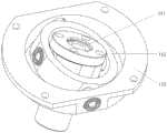
如图1所示是一种采用被动弹簧张紧的索驱动并联分拣机器人的整体示意图,主要由静平台1、驱动组件2、张紧组件3、滑轮组件4和动平台组件5组成。Figure 1 is an overall schematic diagram of a cable-driven parallel sorting robot using passive spring tension.
其中静平台1起固定和安装作用,静平台1上提供各组件的安装连接位置和接口。驱动组件2安装在静平台1上,驱动组件2一共有三组,在静平台1上呈圆周均布,每组驱动组件2由驱动安装座27、伺服电机22、减速器21、编码器23、滚筒24、滚筒轴28、联轴器26和绳索25组成。张紧组件3由若干弹簧31和一根刚性杆32组成,弹簧31的一端通过弹簧固定端子34固定在静平台1上,另一端与刚性杆32的顶端连接。动平台组件5主要由连接套51,万向节52,动平台53,索连接点54和吸盘55组成。The static platform 1 plays the role of fixing and installation, and the static platform 1 provides the installation connection position and interface of each component. The
如图2所示示意了刚性杆32与静平台1和动平台53的连接方式,以及动平台组件5的详细结构。结合图1,刚性杆32一端通过弹簧结33与弹簧31连接,另一端则通过连接套51与动平台53连接。刚性杆32穿过静平台1,并通过静平台1上的复合铰链11与静平台1连接。复合铰链11由万向节与移动副组成,如图3所示详细表达了复合铰链11的结构。复合铰链由内环111,外环112和铰链座113组成。铰链座113通过螺钉固定在静平台1中心。外环112与铰链座113之间有一个转动副,允许二者之间相互转动,外环112与内环111之间有一个转动副,上述两个转动副转动中心线相互垂直,二者共同构成万向铰链,允许内环111绕中心点摆动。内环111为中通结构,中心通孔内部含有滚珠,刚性杆32从内环111中心孔穿过,在滚珠的作用下,刚性杆32可以在孔中自由滑动。因此,刚性杆32可绕中心点摆动,同时可沿自身轴线方向移动。刚性杆底部通过连接套51与动平台组件5相连,连接套51与动平台53之间通过万向节52连接,刚性杆32与动平台53之间可绕万向节52转动中心摆动。动平台53为三角形结构,每条边通过两端的索连接点54各连接一组绳索25。每条边两端的索连接点54距离与绳索25在静平台1上的出索点距离一致,因此,每边连接的两根绳索25相互平行。三组平行索保证了在绳索25张紧的条件下动平台53始终与静平台1平行,因此动平台53可实现三自由度平动。动平台53底部安装有吸盘55,通过真空吸附,可以实现物品的抓取和释放,从而实现分拣操作。As shown in FIG. 2 , the connection manner of the
如图4所示为驱动组件2的结构及连接示意图。驱动组件由驱动安装座27、伺服电机22、减速器21、编码器23、联轴器26、滚筒24、滚筒轴28和绳索25组成。其中,伺服电机22通过减速器21和编码器23连接滚筒轴28,通过伺服电机22的转动从而带动滚筒24的转动。滚筒24两端分别缠绕有绳索25,每个滚筒24连接的两根绳索25通过滑轮组件4后连接动平台53的一条边。滚筒24上刻有螺旋形凹槽,用于绳索25的缠绕。运动时,滚筒24转动实现绳索25的卷绕或释放,每组绳索25卷绕或释放的长度始终一致,从而保证每组索中的两根绳索25始终平行。通过绳索25的长度变化驱动动平台53实现三自由度平移运动。伺服电机22尾部安装有编码器23,通过编码器23反馈伺服电机22转动角度,实现反馈控制,另一方面通过伺服电机22转动角度计算绳索25长度,从而通过正运动学计算终端位置。FIG. 4 is a schematic diagram of the structure and connection of the
如图5和图6示意了滑轮组件4的详细结构,滑轮组件对绳索起到引导和转向的作用。滑轮组件4分为上下两个部分。上部分由上滑轮41,上滑轮轴42和上滑轮座43组成。上滑轮41通过上滑轮轴42安装于上滑轮座43上,上滑轮座43安装在静平台1上。下部分主要由套筒44,转动座45,凹槽轴承46,轴承轴47,侧壁48和水平轴承49组成。下部分通过套筒44安装在静平台1下方,套筒44为空心结构。绳索25从滚筒24引出,经过上滑轮41后向下,从套筒44中心穿过,并绕过凹槽轴承46,然后与底部动平台53连接。凹槽轴承46有2个,外圈相切,两个轴承的凹槽部分形成一个比绳索25直径略大的通孔,绳索25从中心通孔穿过。凹槽轴承46通过轴承轴47安装在侧壁48上,侧壁48安装在转动座45上,转动座45通过水平轴承49安装在套筒44上。整个下部滑轮系统可以绕套筒44的竖直中心轴转动,从而使得凹槽轴承46和侧壁48可以跟随绳索25产生摆动,使得绳索25始终处于凹槽轴承46的中心平面中。Figures 5 and 6 illustrate the detailed structure of the
机构工作过程和原理如下:The working process and principles of the organization are as follows:
动平台53由三组平行绳索25分别连接至三个驱动组件2的滚筒24上,装配时调整动平台53姿态水平且每组平行索两根绳索25长度一致。工作时通过逆运动学计算各绳索25实时长度,通过控制伺服电机22转动从而实现绳索25的收放,进而驱动终端动平台53实现三自由度平移运动。运动过程中,各组平行绳索25将产生摆动,滑轮组件4下方凹槽轴承46可实现随动摆动。The moving
在运动过程中,保证绳索25张紧是实现稳定和高速运动的关键。为实现这一功能,采用被动弹簧和刚性杆32向动平台53施加向下的推力。如图1所示,在静平台1上方分布有若干个弹簧31,弹簧31一端通过弹簧固定端子34连接在静平台1上,另一端固定在刚性杆32顶点处的弹簧结33上。工作时保证弹簧31始终处于拉伸状态,各弹簧31作用于刚性杆32上的弹簧31拉力通过刚性杆32传递到动平台53,表现为对动平台53的向下的推力作用。上方弹簧25的数量是可以根据要求调整的,通过调整弹簧25可以实现张紧力调整,从而调整机构的加速度能力和机构刚度。During the movement, keeping the
在上述设计中,刚性杆32与静平台1之间的连接并不是必须的,即复合铰链11是可以去除的。如图7示意了本发明的另一种实现方式。与图1中的实现方式不同的是,图7的实现方式中,刚性杆32与静平台1之间无连接。在功能上,图7的实现方式与图1是一致的。In the above design, the connection between the
值得注意的是,尽管上面结合附图对本发明的技术方案和优选实施例进行了详细描述,但本发明并不仅仅局限于上述的具体实施方式,上述的实施方式仅仅是示意性的,本领域的相关技术人员受本发明的启示,在不脱离本发明宗旨和权利要求保护范围的情况下,还可以做出很多形式,这些均属于本发明的保护范围。It should be noted that although the technical solutions and preferred embodiments of the present invention have been described in detail above with reference to the accompanying drawings, the present invention is not limited to the above-mentioned specific embodiments, which are only illustrative, and the art Relevant persons skilled in the art are inspired by the present invention, and can make many forms without departing from the spirit of the present invention and the protection scope of the claims, which all belong to the protection scope of the present invention.
Claims (10)
Translated fromChinesePriority Applications (1)
| Application Number | Priority Date | Filing Date | Title |
|---|---|---|---|
| CN201910667042.3ACN110315511B (en) | 2019-07-23 | 2019-07-23 | Cable-driven parallel sorting robot tensioned by passive springs |
Applications Claiming Priority (1)
| Application Number | Priority Date | Filing Date | Title |
|---|---|---|---|
| CN201910667042.3ACN110315511B (en) | 2019-07-23 | 2019-07-23 | Cable-driven parallel sorting robot tensioned by passive springs |
Publications (2)
| Publication Number | Publication Date |
|---|---|
| CN110315511A CN110315511A (en) | 2019-10-11 |
| CN110315511Btrue CN110315511B (en) | 2020-08-25 |
Family
ID=68124199
Family Applications (1)
| Application Number | Title | Priority Date | Filing Date |
|---|---|---|---|
| CN201910667042.3AActiveCN110315511B (en) | 2019-07-23 | 2019-07-23 | Cable-driven parallel sorting robot tensioned by passive springs |
Country Status (1)
| Country | Link |
|---|---|
| CN (1) | CN110315511B (en) |
Families Citing this family (23)
| Publication number | Priority date | Publication date | Assignee | Title |
|---|---|---|---|---|
| CN110723255B (en)* | 2019-10-24 | 2020-07-14 | 上海大学 | An unmanned boat deployment and recovery device based on rope parallel robot |
| CN110666835B (en)* | 2019-10-29 | 2025-02-14 | 中国科学院宁波材料技术与工程研究所 | A rope-driven joint and rope-driven mechanical arm for realizing flexible buffering |
| CN111251278B (en)* | 2020-03-12 | 2021-06-08 | 广东省智行机器人科技有限公司 | Rigid-flexible coupling three-rotation parallel robot |
| CN111496840B (en)* | 2020-06-11 | 2021-09-24 | 山东大学 | A multi-degree-of-freedom variable-stiffness robot joint based on a tensegrity structure and its working method |
| CN111659566B (en)* | 2020-06-16 | 2021-07-23 | 合肥工业大学 | A rope-pulled grinding, cleaning and painting integrated operation robot |
| CN111846005B (en)* | 2020-07-21 | 2022-01-18 | 山东大学 | Bionic quadruped robot based on integral tensioning structure |
| CN112026951B (en)* | 2020-07-29 | 2022-04-19 | 天津大学 | Modular tensegrity multi-legged robot |
| CN112025740B (en)* | 2020-07-29 | 2022-07-05 | 天津大学 | Force feedback device for tensioning integral structure |
| CN111891770A (en)* | 2020-08-27 | 2020-11-06 | 北京品创智能科技有限公司 | A flexible cable-based loading robot |
| CN112304742A (en)* | 2020-11-13 | 2021-02-02 | 长春工业大学 | Flexible parallel mechanism test device based on rope drive |
| CN114211475B (en)* | 2021-12-31 | 2023-10-20 | 上海交通大学 | Rope and elastic rod piece hybrid drive parallel robot |
| CN114393566B (en)* | 2022-01-20 | 2023-09-08 | 清华大学 | Light-weight high-speed four-degree-of-freedom cable-driven parallel robot |
| CN114393565B (en)* | 2022-01-20 | 2023-09-05 | 清华大学 | Rope-driven high-precision two-degree-of-freedom parallel robot |
| CN114434423B (en)* | 2022-01-20 | 2023-09-05 | 清华大学 | Planar two-degree-of-freedom parallel robot driven by parallel cables |
| CN114393567B (en)* | 2022-01-20 | 2023-09-08 | 清华大学 | Rope-driven parallel robot with three-dimensional translation and one-dimensional rotation |
| CN114454152A (en)* | 2022-02-21 | 2022-05-10 | 清华大学 | Rope-driven stacking robot |
| CN114905488A (en)* | 2022-05-07 | 2022-08-16 | 湖南大学 | A cable-driven mechanical device with two rotational degrees of freedom |
| CN115741659A (en)* | 2022-12-09 | 2023-03-07 | 哈尔滨工业大学(深圳) | Rope-driven unmanned aerial vehicle based on inertia flywheel attitude adjustment |
| CN116394226B (en)* | 2023-04-25 | 2024-12-24 | 南京信息工程大学 | Four-degree-of-freedom robot end effector driven by parallel ropes and screw rods in mixed mode |
| CN117140487B (en)* | 2023-10-19 | 2024-11-22 | 东南大学 | A rigid-flexible coupling redundantly driven parallel robot for friction stir additive manufacturing |
| CN117733822B (en)* | 2023-12-28 | 2025-09-09 | 常州大学 | Large-rotation-angle five-degree-of-freedom series-parallel robot |
| CN118721155B (en)* | 2024-07-02 | 2025-02-11 | 机器时代(北京)科技有限公司 | Parallel robotic arm, parallel robot and plant topping equipment |
| CN119704216A (en)* | 2024-12-19 | 2025-03-28 | 西安电子科技大学 | Single-motor worm gear rope driven continuum robot |
Family Cites Families (7)
| Publication number | Priority date | Publication date | Assignee | Title |
|---|---|---|---|---|
| US4666362A (en)* | 1985-05-07 | 1987-05-19 | Massachusetts Institute Of Technology | Parallel link manipulators |
| CH703454B1 (en)* | 2010-07-16 | 2014-06-30 | Jossi Holding Ag | An apparatus for positioning an object, in particular a pipette. |
| CN102357882A (en)* | 2011-09-30 | 2012-02-22 | 汕头大学 | Rope and rod hybrid-driven six-degree-of-freedom parallel robot with few branched chains |
| CN103895005B (en)* | 2014-04-10 | 2017-02-01 | 东南大学 | Humanoid-neck parallel robot and control method thereof |
| CN104647367B (en)* | 2014-12-29 | 2016-05-25 | 合肥工业大学 | The robot palletizer in parallel of the compound driving of a kind of rope bar |
| KR101950669B1 (en)* | 2017-07-07 | 2019-02-21 | 전남대학교산학협력단 | A cable robot for carrying cylindrical object |
| CN109454635B (en)* | 2018-10-15 | 2020-09-25 | 山东中衡光电科技有限公司 | Steel wire flexible cable parallel mirror surface machining device based on lever principle |
- 2019
- 2019-07-23CNCN201910667042.3Apatent/CN110315511B/enactiveActive
Also Published As
| Publication number | Publication date |
|---|---|
| CN110315511A (en) | 2019-10-11 |
Similar Documents
| Publication | Publication Date | Title |
|---|---|---|
| CN110315511B (en) | Cable-driven parallel sorting robot tensioned by passive springs | |
| CN109605333B (en) | A spring-rope hybrid drive branch chain and a parallel robot with three rotational degrees of freedom | |
| CN109848975B (en) | A rope-driven series-parallel hybrid mechanism for large-load manipulators | |
| US7367771B2 (en) | Light weight parallel manipulators using active/passive cables | |
| US11364626B2 (en) | 6-dof parallel robot with a double-gyroscopic component | |
| CN101863018B (en) | Three-rotational-freedom parallel mechanism driven by rope | |
| CN100410029C (en) | A four-degree-of-freedom hybrid pick-and-place robot mechanism capable of full rotation | |
| CN110202559A (en) | One kind is towards the bionical lightweight mechanical arm of man-machine collaboration | |
| CN114393566B (en) | Light-weight high-speed four-degree-of-freedom cable-driven parallel robot | |
| CN110154045B (en) | Flexible cable-driven series-connection four-degree-of-freedom spraying mechanical arm | |
| CN105150190A (en) | Six-freedom-degree bionic mechanical arm based on pneumatic muscle | |
| CN114393567B (en) | Rope-driven parallel robot with three-dimensional translation and one-dimensional rotation | |
| CN115446866A (en) | Light-weight high-torque rope-driven double-degree-of-freedom joint mechanism | |
| CN115488873B (en) | A low-input cable-driven variable-stiffness seven-DOF manipulator | |
| CN114434423B (en) | Planar two-degree-of-freedom parallel robot driven by parallel cables | |
| CN115890629A (en) | Bionic Manipulator Based on Three Parallel Spherical Joints | |
| WO2023138071A1 (en) | Under-actuated continuum mechanical arm | |
| JP2012045710A (en) | Parallel mechanism | |
| CN108789397A (en) | A kind of Three Degree Of Freedom rope driven Parallel Kinematic Manipulator with tension amplification mechanism | |
| CN106625591B (en) | Three-translation two-rotation five-degree-of-freedom parallel mechanism | |
| WO2025138909A1 (en) | Large-range-of motion two-degree-of-freedom wrist structure | |
| CN104476566A (en) | Three-branch and six-degree-of-freedom parallel mechanism with rope-driven joint | |
| CN218592980U (en) | Bionic mechanical arm based on three parallel spherical joints | |
| CN108995727B (en) | A pneumatic muscle-driven Delta robot | |
| CN106737599B (en) | A kind of moving platform mechanism equipped with ball-screw |
Legal Events
| Date | Code | Title | Description |
|---|---|---|---|
| PB01 | Publication | ||
| PB01 | Publication | ||
| SE01 | Entry into force of request for substantive examination | ||
| SE01 | Entry into force of request for substantive examination | ||
| GR01 | Patent grant | ||
| GR01 | Patent grant |