CN110301947B - Tissue spreader under laparoscope - Google Patents
Tissue spreader under laparoscopeDownload PDFInfo
- Publication number
- CN110301947B CN110301947BCN201910464603.XACN201910464603ACN110301947BCN 110301947 BCN110301947 BCN 110301947BCN 201910464603 ACN201910464603 ACN 201910464603ACN 110301947 BCN110301947 BCN 110301947B
- Authority
- CN
- China
- Prior art keywords
- support
- support plate
- seat
- link
- shell
- Prior art date
- Legal status (The legal status is an assumption and is not a legal conclusion. Google has not performed a legal analysis and makes no representation as to the accuracy of the status listed.)
- Active
Links
Images


Classifications
- A—HUMAN NECESSITIES
- A61—MEDICAL OR VETERINARY SCIENCE; HYGIENE
- A61B—DIAGNOSIS; SURGERY; IDENTIFICATION
- A61B17/00—Surgical instruments, devices or methods
- A61B17/02—Surgical instruments, devices or methods for holding wounds open, e.g. retractors; Tractors
- A61B17/0218—Surgical instruments, devices or methods for holding wounds open, e.g. retractors; Tractors for minimally invasive surgery
Landscapes
- Health & Medical Sciences (AREA)
- Life Sciences & Earth Sciences (AREA)
- Surgery (AREA)
- Heart & Thoracic Surgery (AREA)
- Engineering & Computer Science (AREA)
- Biomedical Technology (AREA)
- Nuclear Medicine, Radiotherapy & Molecular Imaging (AREA)
- Medical Informatics (AREA)
- Molecular Biology (AREA)
- Animal Behavior & Ethology (AREA)
- General Health & Medical Sciences (AREA)
- Public Health (AREA)
- Veterinary Medicine (AREA)
- Endoscopes (AREA)
Abstract
Translated fromChinese
Description
Translated fromChinese技术领域technical field
本发明涉及医疗器械技术领域,尤其涉及一种腹腔镜下组织撑开器。The invention relates to the technical field of medical devices, in particular to a laparoscopic tissue spreader.
背景技术Background technique
本部分提供的仅仅是与本公开相关的背景信息,其并不必然是现有技术。This section provides merely background information related to the present disclosure and is not necessarily prior art.
伴随着科技的不断进步,医疗技术和水平得到了长足的发展,使得疾病的治疗效果越来越好,患者在疾病治疗过程中的痛苦越来越小。With the continuous progress of science and technology, medical technology and level have been developed by leaps and bounds, making the treatment effect of the disease better and better, and the pain of patients in the process of disease treatment is getting smaller and smaller.
以腹内手术为例,传统手术中,需要打开患者的腹部,对患者进行开放性手术,但是,该种方式的风险大、费用高、创伤大、恢复周期长,为了解决传统手术中的不足,腹腔镜手术逐渐发展成熟。Taking intra-abdominal surgery as an example, in traditional surgery, it is necessary to open the patient's abdomen and perform open surgery on the patient. However, this method has high risks, high costs, large trauma, and long recovery period. In order to solve the shortcomings of traditional surgery , Laparoscopic surgery has gradually developed and matured.
进行腹腔镜手术时,在患者腹部开设微型创口,腹腔镜经微型创口伸入到患者腹腔内,腹腔镜的镜头能够为医生提供更开阔、更清晰的视野,但是,患者腹内的组织易于出现遮挡腹腔镜的镜头以及限制手术空间的情况,一般利用器械及纱条等支撑结构将患者腹腔内的组织及脏器撑开,从而保证医生的观看视野及手术空间,使得手术顺利进行。During laparoscopic surgery, a micro incision is made in the patient's abdomen, and the laparoscope is inserted into the patient's abdominal cavity through the micro incision. The lens of the laparoscope can provide the doctor with a wider and clearer view, but the tissue in the patient's abdomen is prone to appear. When the lens of the laparoscope is blocked and the operation space is limited, the supporting structures such as instruments and gauze are generally used to spread the tissues and organs in the patient's abdominal cavity, so as to ensure the doctor's viewing field and operation space, so that the operation can be carried out smoothly.
但是,器械及纱条等支撑结构在将组织、脏器撑开时,会占用患者的微型创口,对手术器械形成阻挡,不利于医生手术过程中对于手术器械的操作,使得医生不得不增加患者微型创口的数量,从而增大了患者腹部创面及患者的手术痛苦。However, when the supporting structures such as instruments and gauze spread the tissues and organs, they will occupy the patient's micro incision and form a block for the surgical instruments, which is not conducive to the operation of the surgical instruments by the doctor during the operation, so that the doctor has to increase the number of patients. The number of micro wounds increases the patient's abdominal wound and the patient's surgical pain.
发明内容SUMMARY OF THE INVENTION
本发明的目的是至少解决支撑结构阻挡手术器械导致增大了患者腹部创面及患者的手术痛苦的问题。该目的是通过以下技术方案实现的:The purpose of the present invention is to at least solve the problem that the support structure blocks the surgical instrument, which increases the patient's abdominal wound surface and the patient's surgical pain. This purpose is achieved through the following technical solutions:
本发明的第一方面提出了一种腹腔镜下组织撑开器,包括:A first aspect of the present invention provides a laparoscopic tissue spreader, comprising:
支撑机构,所述支撑机构包括支撑架、第一支撑板和第二支撑板,所述第一支撑板和所述第二支撑板分别安装于所述支撑架的两个相对侧;a support mechanism, the support mechanism includes a support frame, a first support plate and a second support plate, the first support plate and the second support plate are respectively installed on two opposite sides of the support frame;
撑开机构,所述撑开机构包括有卡持件和驱动件,所述卡持件与所述支撑架以可分离的方式连接,以将所述支撑机构送至或带离支撑位置,所述驱动件能够与所述支撑架配合,以使所述第一支撑板与所述第二支撑板相离或相向运动。A spreading mechanism, the spreading mechanism includes a holding member and a driving member, the holding member and the supporting frame are connected in a detachable manner, so as to send the supporting mechanism to or take away from the supporting position, so The driving member can cooperate with the supporting frame, so that the first supporting plate and the second supporting plate move away from each other or move toward each other.
根据本发明的腹腔镜下组织撑开器,该腹腔镜下组织撑开器包括独立的支撑机构和撑开机构,在未使用状态下,两者为分离状态,支撑机构处于收起姿态。在进行手术时,如果需要对患者的组织进行支撑,将撑开机构的卡持件与支撑机构配合,使得卡持件对支撑机构进行卡持,移动撑开机构,从而带动支撑机构到达支撑位置,撑开机构的驱动件与支撑机构的支撑架配合,并驱动支撑架展开,由于第一支撑板和第二支撑板分别位于支撑架的两个相对的侧面上,支撑架展开过程中,第一支撑板和第二支撑板相离运动,从而将患者的组织推开,从而形成空间,当形成的空间满足医生的查看及手术要求时,卡持件及驱动件均与支撑机构分离,撑开机构撤离,医生对患者的手术位置进行查看及手术;当医生查看及手术完成后,撑开机构再次与支撑机构配合,驱动件驱动支撑架反向运动进行收起,第一支撑板和第二支撑板相向运动,逐渐将推开的组织恢复,当支撑架完全收起后,卡持件对支撑架进行卡持,通过移动撑开机构使得支撑机构被带离支撑位置,从而完成对患者组织的支撑。According to the laparoscopic tissue spreader of the present invention, the laparoscopic tissue spreader includes an independent support mechanism and a spreader mechanism, and in an unused state, the two are separated, and the support mechanism is in a retracted posture. During the operation, if the patient's tissue needs to be supported, the holder of the spreading mechanism is matched with the support mechanism, so that the holder can hold the support mechanism and move the spreading mechanism, thereby driving the support mechanism to the support position , the driving member of the spreading mechanism cooperates with the supporting frame of the supporting mechanism, and drives the supporting frame to unfold. Since the first supporting plate and the second supporting plate are respectively located on two opposite sides of the supporting frame, during the unfolding process of the supporting frame, the The first support plate and the second support plate move away from each other, so as to push the patient's tissue away, thereby forming a space. When the space formed meets the doctor's inspection and operation requirements, the holding member and the driving member are separated from the support mechanism. The opening mechanism is evacuated, and the doctor inspects and operates on the patient's operating position; when the doctor inspects and completes the operation, the opening mechanism cooperates with the support mechanism again, and the driving member drives the support frame to move in the opposite direction to retract, the first support plate and the first support plate. The two support plates move towards each other, and gradually restore the pushed open tissue. When the support frame is completely retracted, the holding member holds the support frame, and the support mechanism is taken away from the support position by moving the opening mechanism, thereby completing the treatment of the patient. organizational support.
上述腹腔镜下组织撑开器的支撑机构展开后为框架结构,第一支撑板和第二支撑板用于将患者的组织撑开,支撑架占用空间小,同时,手术器械可穿过支撑架进行操作,从而避免再次开设微型创口,减小了患者腹部创面及患者的手术痛苦;同时,该腹腔镜下组织撑开器的结构简单,制造成本低,操作便捷,支撑效果佳,能够有效满足使用需求,另外,支撑机构对患者组织的支撑为机械支撑,支撑过程中对患者的影响极小,提高了使用的范围及通用性。The support mechanism of the above-mentioned laparoscopic tissue spreader is unfolded into a frame structure, the first support plate and the second support plate are used to spread the patient's tissue, the support frame occupies a small space, and at the same time, surgical instruments can pass through the support frame operation, so as to avoid opening a micro wound again, reducing the abdominal wound surface of the patient and the pain of the patient's operation; at the same time, the laparoscopic tissue spreader has a simple structure, low manufacturing cost, convenient operation, good support effect, and can effectively meet the needs of the patient. In addition, the support mechanism for the patient's tissue is mechanical support, and the impact on the patient during the support process is extremely small, which improves the scope and versatility of use.
另外,根据本发明的腹腔镜下组织撑开器,还可具有如下附加的技术特征:In addition, the laparoscopic tissue spreader according to the present invention may further have the following additional technical features:
在本发明的一些实施例中,所述支撑架包括:In some embodiments of the present invention, the support frame includes:
螺杆,所述螺杆的一端形成有配合孔,所述驱动件能够插入所述配合孔,以便驱动所述螺杆转动;a screw, one end of the screw is formed with a matching hole, and the driving member can be inserted into the matching hole so as to drive the screw to rotate;
第一座,所述第一座以可转动的方式套装在所述螺杆的外侧;a first seat, the first seat is rotatably sleeved on the outer side of the screw rod;
第二座,所述第二座套装在所述螺杆的外侧并且与所述螺杆螺纹配合;a second seat, the second seat is sleeved on the outer side of the screw rod and is threadedly matched with the screw rod;
第一连杆,所述第一连杆的一端以可转动的方式与所述第一座连接,所述第一连杆的另一端与所述第一支撑板铰接;a first link, one end of the first link is rotatably connected with the first seat, and the other end of the first link is hinged with the first support plate;
第二连杆,所述第二连杆的一端以可转动的方式与所述第二座连接,所述第二连杆的另一端与所述第一支撑板铰接;a second connecting rod, one end of the second connecting rod is rotatably connected with the second seat, and the other end of the second connecting rod is hinged with the first support plate;
第三连杆,所述第三连杆的一端以可转动的方式与所述第一座连接,并且与所述第一连杆分置在所述第一座的两侧,所述第三连杆的另一端与所述第二支撑板铰接;A third connecting rod, one end of the third connecting rod is rotatably connected to the first seat, and is separated from the first connecting rod on both sides of the first seat, the third connecting rod is The other end of the connecting rod is hinged with the second support plate;
第四连杆,所述第四连杆的一端以可转动的方式与所述第二座连接,并且与所述第二连杆分置在所述第二座的两侧,所述第四连杆的另一端与所述第二支撑板连接。a fourth connecting rod, one end of the fourth connecting rod is rotatably connected to the second seat, and is separated from the second connecting rod on both sides of the second seat, the fourth connecting rod is The other end of the connecting rod is connected with the second support plate.
在本发明的一些实施例中,所述第一支撑板为第一半壳,所述第二支撑板为第二半壳,在所述支撑架收起状态时,所述第一半壳和所述第二半壳彼此扣装,以便形成柱状壳体,所述第二座、所述第一连杆、所述第二连杆、所述第三连杆和所述第四连杆能够收容于所述柱状壳体的内部,所述第一座的部分本体和所述螺杆的部分本体分别位于所述柱状壳体的外部。In some embodiments of the present invention, the first support plate is a first half-shell, the second support plate is a second half-shell, and when the support frame is in a retracted state, the first half-shell and The second half shells are snap-fitted to each other to form a cylindrical housing, the second seat, the first link, the second link, the third link and the fourth link are capable of It is accommodated inside the cylindrical housing, and the partial body of the first seat and the partial body of the screw rod are respectively located outside the cylindrical housing.
在本发明的一些实施例中,所述支撑机构还包括:In some embodiments of the present invention, the support mechanism further includes:
电源,所述电源内置于所述第一座的内部;a power source, the power source is built into the interior of the first seat;
距离感应开关,所述距离感应开关安装于所述第二座,并且所述距离感应开关的工作端朝向所述第一座;a distance sensing switch, the distance sensing switch is installed on the second seat, and the working end of the distance sensing switch faces the first seat;
多个第一发光体,各所述第一发光体均布于所述第一半壳朝向所述第二半壳的侧面上,并且各所述第一发光体均通过所述距离感应开关与所述电源电连接。A plurality of first luminous bodies, each of the first luminous bodies is evenly distributed on the side of the first half-shell facing the second half-shell, and each of the first luminous bodies is connected to the distance sensing switch through the distance sensing switch. The power supply is electrically connected.
在本发明的一些实施例中,所述支撑机构还包括:In some embodiments of the present invention, the support mechanism further includes:
多个第二发光体,各所述第二发光体均布于所述第二半壳朝向所述第一半壳的侧面上,并且各所述第二发光体均通过所述距离感应开关与所述电源电连接。A plurality of second luminous bodies, each of the second luminous bodies is evenly distributed on the side of the second half-shell facing the first half-shell, and each of the second luminous bodies is connected to the distance sensing switch through the distance sensing switch. The power supply is electrically connected.
在本发明的一些实施例中,所述驱动件为磁力件,所述螺杆为能够被所述磁力件吸附的金属件,所述驱动件通过磁性吸合插入所述配合孔。In some embodiments of the present invention, the driving member is a magnetic member, the screw rod is a metal member that can be attracted by the magnetic member, and the driving member is inserted into the matching hole through magnetic attraction.
在本发明的一些实施例中,所述配合孔为矩形孔、三角孔、十字孔或梅花孔中的任一种,所述驱动件的插入端与所述配合孔的形状相适配。In some embodiments of the present invention, the matching hole is any one of a rectangular hole, a triangular hole, a cross hole or a plum blossom hole, and the insertion end of the driving member is adapted to the shape of the matching hole.
在本发明的一些实施例中,所述撑开机构还包括:In some embodiments of the present invention, the expansion mechanism further comprises:
调节杆,所述调节杆的一端形成有调节头,所述调节杆的另一端与所述驱动件连接;an adjusting rod, one end of the adjusting rod is formed with an adjusting head, and the other end of the adjusting rod is connected with the driving member;
拉管,所述拉管同轴套装在所述调节杆的外侧,所述拉管的一端的径向外侧形成有驱动臂,所述拉管的另一端与所述卡持件连接,所述卡持件套装在所述驱动件的外侧,并且所述调节头位于所述拉管的所述一端的外侧;a pulling tube, the pulling tube is coaxially sleeved on the outer side of the adjusting rod, a drive arm is formed on the radial outer side of one end of the pulling tube, the other end of the pulling tube is connected with the clamping part, and the The clamping part is sleeved on the outer side of the driving part, and the adjusting head is located at the outer side of the one end of the pulling tube;
套筒,所述套筒套装在所述拉管的外侧,所述卡持件的部分本体能够凸出于所述套筒的一端,所述套筒的另一端的径向外侧形成有把手,所述驱动臂位于所述套筒的所述另一端的外侧;a sleeve, the sleeve is sleeved on the outer side of the pulling tube, a part of the body of the holding member can protrude from one end of the sleeve, and a handle is formed on the radial outer side of the other end of the sleeve, the drive arm is located outside the other end of the sleeve;
扳手,所述扳手以可转动的方式设置在所述把手靠近所述套筒的一侧;a wrench, which is rotatably arranged on the side of the handle close to the sleeve;
顶杆,所述顶杆以可移动的方式设置在所述把手上,所述顶杆的一端抵靠在所述驱动臂上,所述顶杆的另一端抵靠在所述扳手上。A top rod is movably arranged on the handle, one end of the top rod abuts on the driving arm, and the other end of the top rod abuts on the wrench.
在本发明的一些实施例中,所述卡持件为管状结构,所述管状结构包括:In some embodiments of the present invention, the holding member is a tubular structure, and the tubular structure includes:
小端,所述小端的外径小于所述套筒的内径,所述小端与所述拉管的所述另一端连接;a small end, the outer diameter of the small end is smaller than the inner diameter of the sleeve, and the small end is connected to the other end of the drawing tube;
大端,所述大端的外径大于所述套筒的内径,所述大端的内壁开设有环形槽,沿所述大端的周向等间隔开设有多个伸缩缝,各所述伸缩缝将所述大端分割成多个可动部,所述拉管带动所述卡持件相对套筒移动时,所述套筒能够使各所述可动部向所述大端的径向内侧靠近,以将位于所述环形槽的所述支撑架的连接端卡持。Big end, the outer diameter of the big end is larger than the inner diameter of the sleeve, the inner wall of the big end is provided with an annular groove, and a plurality of expansion joints are equally spaced along the circumference of the big end, each of the expansion joints The big end is divided into a plurality of movable parts, and when the pulling tube drives the holding member to move relative to the sleeve, the sleeve can make each movable part approach the radial inner side of the big end, so as to prevent The connecting end of the support frame located in the annular groove is clamped.
在本发明的一些实施例中,所述卡持件上还开设有加强孔,所述加强孔的数量与所述伸缩缝的数量一致,各所述加强孔分别位于各所述伸缩缝的底部。In some embodiments of the present invention, reinforcement holes are further opened on the holding member, the number of the reinforcement holes is the same as the number of the expansion joints, and each of the reinforcement holes is located at the bottom of each of the expansion joints. .
附图说明Description of drawings
通过阅读下文优选实施方式的详细描述,各种其他的优点和益处对于本领域普通技术人员将变得清楚明了。附图仅用于示出优选实施方式的目的,而并不认为是对本发明的限制。而且在整个附图中,用相同的附图标记表示相同的部件。在附图中:Various other advantages and benefits will become apparent to those of ordinary skill in the art upon reading the following detailed description of the preferred embodiments. The drawings are for the purpose of illustrating preferred embodiments only and are not to be considered limiting of the invention. Also, the same components are denoted by the same reference numerals throughout the drawings. In the attached image:
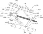
图1示意性地示出了根据本发明实施方式的腹腔镜下组织撑开器的结构示意图(支撑装置处于收起状态);FIG. 1 schematically shows a schematic structural diagram of a laparoscopic tissue spreader according to an embodiment of the present invention (the support device is in a retracted state);
图2示意性地示出了根据本发明实施方式的腹腔镜下组织撑开器的结构示意图(支撑装置处于展开状态);FIG. 2 schematically shows a schematic structural diagram of a laparoscopic tissue spreader according to an embodiment of the present invention (the support device is in a deployed state);
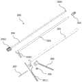
图3为图2中所示腹腔镜下组织撑开器中支撑机构的结构示意图;Fig. 3 is the structural schematic diagram of the support mechanism in the laparoscopic tissue spreader shown in Fig. 2;
图4为图3中所示的支撑机构的结构分解示意图;Fig. 4 is the structural exploded schematic diagram of the support mechanism shown in Fig. 3;
图5为图2中所示腹腔镜下组织撑开器中撑开机构的结构示意图;Fig. 5 is the structural schematic diagram of the opening mechanism in the laparoscopic tissue opening device shown in Fig. 2;
图6为图5中所示的撑开机构的结构分解示意图;FIG. 6 is a schematic exploded view of the structure of the spreading mechanism shown in FIG. 5;
图7为调节杆与支撑机构配合的结构示意图;Fig. 7 is the structural schematic diagram that the adjustment rod and the support mechanism cooperate;
图8为图7中A部的放大结构示意图;Fig. 8 is the enlarged structural schematic diagram of part A in Fig. 7;
图9为拉管与支撑机构配合的结构示意图;FIG. 9 is a schematic structural diagram of the cooperation between the pulling tube and the supporting mechanism;
图10为图9中B部的放大结构示意图;Fig. 10 is the enlarged structural schematic diagram of B part in Fig. 9;
图11为图10中所示的B部放大结构剖视图;FIG. 11 is a cross-sectional view of the enlarged structure of part B shown in FIG. 10;
图12为卡持件的结构示意图。FIG. 12 is a schematic structural diagram of a holder.
100为支撑机构,200为撑开机构;100 is the support mechanism, 200 is the opening mechanism;
101为第一支撑板,1011,为第一孔,1012为第一连接座,102为第二支撑板,1021为第二孔,103为支撑架,1031为第一发光体,1032为第一连杆,10321为第一杆部,10322为第二杆部,1033为第二连杆,1034为第一座,10341为环形凸台,1035为第二座,1036为距离感应开关,1037为螺杆,10371为配合孔,1038为第三连杆,10381为第三杆部,10382为第四杆部,1039为第四连杆;101 is the first support plate, 1011 is the first hole, 1012 is the first connection seat, 102 is the second support plate, 1021 is the second hole, 103 is the support frame, 1031 is the first luminous body, 1032 is the first Connecting rod, 10321 is the first rod, 10322 is the second rod, 1033 is the second connecting rod, 1034 is the first seat, 10341 is the annular boss, 1035 is the second seat, 1036 is the distance sensing switch, 1037 is the Screw, 10371 is the matching hole, 1038 is the third connecting rod, 10381 is the third rod portion, 10382 is the fourth rod portion, and 1039 is the fourth connecting rod;
201为套筒,2011为把手,202为卡持件,2021为大端,2022为小端,2023为环形槽,2024为伸缩缝,2025为加强孔,203为拉管,2031为驱动臂,204为调节杆,2041为驱动件,2042为调节头,205为销轴,206为扳手,207为顶杆。201 is the sleeve, 2011 is the handle, 202 is the holder, 2021 is the big end, 2022 is the small end, 2023 is the annular groove, 2024 is the expansion joint, 2025 is the reinforcement hole, 203 is the pull tube, 2031 is the drive arm, 204 is an adjusting rod, 2041 is a driving member, 2042 is an adjusting head, 205 is a pin, 206 is a wrench, and 207 is a top rod.
具体实施方式Detailed ways
下面将参照附图更详细地描述本公开的示例性实施方式。虽然附图中显示了本公开的示例性实施方式,然而应当理解,可以以各种形式实现本公开而不应被这里阐述的实施方式所限制。相反,提供这些实施方式是为了能够更透彻地理解本公开,并且能够将本公开的范围完整的传达给本领域的技术人员。Exemplary embodiments of the present disclosure will be described in more detail below with reference to the accompanying drawings. While exemplary embodiments of the present disclosure are shown in the drawings, it should be understood that the present disclosure may be embodied in various forms and should not be limited by the embodiments set forth herein. Rather, these embodiments are provided so that the present disclosure will be more thoroughly understood, and will fully convey the scope of the present disclosure to those skilled in the art.
应理解的是,文中使用的术语仅出于描述特定示例实施方式的目的,而无意于进行限制。除非上下文另外明确地指出,否则如文中使用的单数形式“一”、“一个”以及“所述”也可以表示包括复数形式。术语“包括”、“包含”、“含有”以及“具有”是包含性的,并且因此指明所陈述的特征、步骤、操作、元件和/或部件的存在,但并不排除存在或者添加一个或多个其它特征、步骤、操作、元件、部件、和/或它们的组合。文中描述的方法步骤、过程、以及操作不解释为必须要求它们以所描述或说明的特定顺序执行,除非明确指出执行顺序。还应当理解,可以使用另外或者替代的步骤。It is to be understood that the terminology used herein is for the purpose of describing particular example embodiments only and is not intended to be limiting. As used herein, the singular forms "a," "an," and "the" can also be intended to include the plural forms unless the context clearly dictates otherwise. The terms "comprising", "comprising", "containing" and "having" are inclusive and thus indicate the presence of stated features, steps, operations, elements and/or components, but do not preclude the presence or addition of one or Various other features, steps, operations, elements, components, and/or combinations thereof. Method steps, procedures, and operations described herein are not to be construed as requiring that they be performed in the particular order described or illustrated, unless an order of performance is explicitly indicated. It should also be understood that additional or alternative steps may be used.
尽管可以在文中使用术语第一、第二、第三等来描述多个元件、部件、区域、层和/或部段,但是,这些元件、部件、区域、层和/或部段不应被这些术语所限制。这些术语可以仅用来将一个元件、部件、区域、层或部段与另一区域、层或部段区分开。除非上下文明确地指出,否则诸如“第一”、“第二”之类的术语以及其它数字术语在文中使用时并不暗示顺序或者次序。因此,以下讨论的第一元件、部件、区域、层或部段在不脱离示例实施方式的教导的情况下可以被称作第二元件、部件、区域、层或部段。Although the terms first, second, third, etc. may be used herein to describe various elements, components, regions, layers and/or sections, these elements, components, regions, layers and/or sections should not be restricted by these terms. These terms may only be used to distinguish one element, component, region, layer or section from another region, layer or section. Terms such as "first," "second," and other numerical terms when used herein do not imply a sequence or order unless clearly indicated by the context. Thus, a first element, component, region, layer or section discussed below could be termed a second element, component, region, layer or section without departing from the teachings of example embodiments.
为了便于描述,可以在文中使用空间相对关系术语来描述如图中示出的一个元件或者特征相对于另一元件或者特征的关系,这些相对关系术语例如为“内部”、“外部”、“内侧”、“外侧”、“下面”、“下方”、“上面”、“上方”等。这种空间相对关系术语意于包括除图中描绘的方位之外的在使用或者操作中装置的不同方位。例如,如果在图中的装置翻转,那么描述为“在其它元件或者特征下面”或者“在其它元件或者特征下方”的元件将随后定向为“在其它元件或者特征上面”或者“在其它元件或者特征上方”。因此,示例术语“在……下方”可以包括在上和在下的方位。装置可以另外定向(旋转90度或者在其它方向)并且文中使用的空间相对关系描述符相应地进行解释。For ease of description, spatially relative terms may be used herein to describe the relationship of one element or feature to another element or feature as shown in the figures, such as "inner", "outer", "inner" ", "outside", "below", "below", "above", "above", etc. This spatially relative term is intended to include different orientations of the device in use or operation other than the orientation depicted in the figures. For example, if the device in the figures is turned over, elements described as "below" or "beneath" other elements or features would then be oriented "above" or "above the other elements or features" above features". Thus, the example term "below" can encompass both an orientation of above and below. The device may be otherwise oriented (rotated 90 degrees or at other orientations) and the spatially relative descriptors used herein interpreted accordingly.
如图1至图6所示,根据本发明的实施方式,提出了一种腹腔镜下组织撑开器,包括支撑机构100和撑开机构200,支撑机构100包括支撑架103、第一支撑板101和第二支撑板102,第一支撑板101和第二支撑板102分别安装于支撑架103的两个相对侧;撑开机构200包括有卡持件202和驱动件2041,卡持件202与支撑架103以可分离的方式连接,以将支撑机构100送至或带离支撑位置,驱动件2041能够与支撑架103配合,以使第一支撑板101与第二支撑板102相离或相向运动。As shown in FIGS. 1 to 6 , according to an embodiment of the present invention, a laparoscopic tissue spreader is proposed, which includes a
根据本发明的腹腔镜下组织撑开器,该腹腔镜下组织撑开器包括独立的支撑机构100和撑开机构200,在未使用状态下,两者为分离状态,支撑机构100处于收起姿态。在进行手术时,如果需要对患者的组织进行支撑,将撑开机构200的卡持件202与支撑机构100配合,使得卡持件202对支撑机构100进行卡持,移动撑开机构200,从而带动支撑机构100到达支撑位置,撑开机构200的驱动件2041与支撑机构100的支撑架103配合,并驱动支撑架103展开,由于第一支撑板101和第二支撑板102分别位于支撑架103的两个相对的侧面上,支撑架103展开过程中,第一支撑板101和第二支撑板102相离运动,从而将患者的组织推开,从而形成空间,当形成的空间满足医生的查看及手术要求时,卡持件202及驱动件2041均与支撑机构100分离,撑开机构200撤离,医生对患者的手术位置进行查看及手术;当医生查看及手术完成后,撑开机构200再次与支撑机构100配合,驱动件2041驱动支撑架103反向运动进行收起,第一支撑板101和第二支撑板102相向运动,逐渐将推开的组织恢复,当支撑架103完全收起后,卡持件202对支撑架103进行卡持,通过移动撑开机构200使得支撑机构100被带离支撑位置,从而完成对患者组织的支撑。According to the laparoscopic tissue spreader of the present invention, the laparoscopic tissue spreader includes an
上述腹腔镜下组织撑开器的支撑机构100展开后为框架结构,第一支撑板101和第二支撑板102用于将患者的组织撑开,支撑架103占用空间小,同时,手术器械可穿过支撑架103进行操作,从而避免再次开设微型创口,减小了患者腹部创面及患者的手术痛苦;同时,该腹腔镜下组织撑开器的结构简单,制造成本低,同时,操作便捷,支撑效果佳,能够有效满足使用需求,另外,支撑机构100对患者组织的支撑为机械支撑,支撑过程中对患者的影响极小,提高了使用的范围及通用性。The
需要理解的是,本申请中的腹腔镜下组织撑开器在应用于腹腔镜手术时,撑开结构具有一定的长度,撑开结构的一端能够与支撑结构连接,通过持握撑开结构的另一端能够将支撑结构送达到支撑位置,从而实现支撑效果。It should be understood that when the laparoscopic tissue spreader in the present application is applied to laparoscopic surgery, the spreader structure has a certain length, and one end of the spreader structure can be connected to the support structure, and by holding the spreader structure The other end can send the support structure to the support position, so as to realize the support effect.
需要指出的是,本申请中第一支撑板101和第二支撑板102均为弧形板,并且第一弧形板和第二弧形板的开口方向相向,通过将第一支撑板101和第二支撑板102设置成弧形结构,能够避免第一支撑板101和第二支撑板102在撑开患者组织时对组织造成的损伤,同时,第一支撑板101和第二支撑板102具有一定的宽度,当第一支撑板101和第二支撑板102相离进行组织支撑时,能够有效增大支撑的空间,从而为手术提供足够的空间,再者,第一支撑板101和第二支撑板102的边缘均进行钝化处理,钝化的方式一般为倒圆角,从而避免第一支撑板101和第二支撑板102在进行支撑时对组织的划伤,有效保证患者使用的安全。It should be pointed out that in the present application, the
如图3和图4所示,在第一支撑板上101开设有多个第一孔1011,各第一孔1011间隔设置在第一支撑板101上,当支撑机构100展开后,第一支撑板101抵靠在患者脏器或组织的表面,由于第一支撑板101对患者脏器或组织具有推力,患者的脏器或组织在反作用力下嵌入到各第一孔1011中,从而形成对第一支撑板101的限位,进而提高了支撑机构100的稳定性,保证支撑机构100的支撑效果。As shown in FIG. 3 and FIG. 4 , a plurality of
如图3和图4所示,在第二支撑板上102开设有多个第二孔1021,各第二孔1021间隔设置在第二支撑板102上,当支撑机构100展开后,第二支撑板102抵靠在患者脏器或组织的表面,由于第二支撑板102对患者脏器或组织具有推力,患者的脏器或组织在反作用力下嵌入到各第二孔1021中,从而形成对第二支撑板102的限位,进而提高了支撑机构100的稳定性,保证支撑机构100的支撑效果.As shown in FIG. 3 and FIG. 4 , a plurality of
另外,支撑机构100中支撑板的数量不仅仅局限于两个,还可以为多个,支撑板的数量为多个时,各支撑板绕支撑架103的外表面间隔设置,当支撑架103处于收缩状态时,各支撑板包覆在支撑架103的外表面,当支撑架103处于展开状态时,各支撑板呈放射状运动(即各支撑板分别向远离支撑架103的方向运动),从而实现患者组织的立体支撑,避免周围组织进入到支撑空间,使得医生查看及手术的空间得到保证。In addition, the number of support plates in the
进一步理解的是,如图3和图4所示,支撑架103包括螺杆1037、第一座1034、第二座1035、第一连杆1032、第二连杆1033、第三连杆1038和第四连杆1039,螺杆1037的一端形成有配合孔10371,驱动件2041能够插入配合孔10371,以便驱动螺杆1037转动;第一座1034以可转动的方式套装在螺杆1037的外侧;第二座1035套装在螺杆1037的外侧并且与螺杆1037螺纹配合;第一连杆1032的一端以可转动的方式与第一座1034连接,第一连杆1032的另一端与第一支撑板101铰接;第二连杆1033的一端以可转动的方式与第二座1035连接,第二连杆1033的另一端与第一支撑板101铰接;第三连杆1038的一端以可转动的方式与第一座1034连接,并且与第一连杆1032分置在第一座1034的两侧,第三连杆1038的另一端与第二支撑板102铰接;第四连杆1039的一端以可转动的方式与第二座1035连接,并且与第二连杆1033分置在第二座1035的两侧,第四连杆1039的另一端与第二支撑板102连接。具体地,第一座1034以可转动的方式套装在螺杆1037的外侧,当螺杆1037转动时,第一座1034仅相对螺杆1037转动,而不相对螺杆1037的轴向产生位移,而第二座1035套装在螺杆1037的外侧,并且与螺杆1037螺纹连接,当螺杆1037转动时,第二座1035能够相对第一座1034进行靠近或者远离运动。It is further understood that, as shown in FIG. 3 and FIG. 4 , the
当第二座1035向靠近第一座1034的方向运动时,第一连杆1032和第二连杆1033之间的夹角减小,使得第一支撑板101向远离螺杆1037的方向运动,同时,第三连杆1038和第四连杆1039之间的夹角减小,使得第二支撑板102向远离螺杆1037的方向运动,由于第一支撑板101和第二支撑板102分别位于螺杆1037的两侧,当第一支撑板101和第二支撑板102相离运动时,实现组织撑开;当第二座1035向远离第一座1034的方向运动时,第一连杆1032和第二连杆1033之间的夹角增大,使得第一支撑板101向靠近螺杆1037的方向运动,同时,第三连杆1038和第四连杆1039之间的夹角增大,使得第二支撑板102向靠近螺杆1037的方向运动,实现组织恢复。When the
需要理解的是,驱动件2041上具有插入端,当需要驱动螺杆1037转动时,插入端插入配合孔10371内,并且与配合孔10371配合,驱动件2041转动,从而驱动螺杆1037转动,进而实现支撑架103的展开或收起,使得组织撑开或恢复。It should be understood that the driving
需要指出的是,第一支撑板101朝向螺杆1037的侧面上设置有第一连接座1012,第一连杆1032远离螺杆1037的一端和第二连杆1033的远离螺杆1037的一端均铰接在第一连接座1012的同一个位置上,更具体的是,第一连杆1032包括第一杆部10321和第二杆部10322,第一杆部10321和第二杆部10322的结构和形状一致,两者平行间隔设置,第二连杆1033远离螺杆1037的一端夹在第一杆部10321和第二杆部10322之间,并且三者通过一根轴铰接在第一连接座1012上,通过第一连杆1032的结构以及第一连杆1032与第二连杆1033及第一连接座1012的连接结构能够有效提高第一支撑板101的支撑强度及稳定性,从而保证支撑效果,使得医生查看及手术顺利进行;第二支撑板102朝向螺杆1037的侧面上设置有第二连接座,第三连杆1038包括第三杆部10381和第四杆部10382,第三杆部10381和第四杆部10382的结构和形状一致,第三连杆1038与第四连杆1039和第二连接座的连接结构及有益效果与第一连杆1032与第二连杆1033和第二连接座相同,在此本申请不再进行赘述。It should be pointed out that the side of the
进一步地,如图1所示,第一支撑板101为第一半壳,第二支撑板102为第二半壳,在支撑架103收起状态时,第一半壳和第二半壳彼此扣装,以便形成柱状壳体,第二座1035、第一连杆1032、第二连杆1033、第三连杆1038和第四连杆1039能够收容于柱状壳体的内部,第一座1034的部分本体和螺杆1037的部分本体分别位于柱状壳体的外部。具体地,第一半壳的开口方向和第二半壳的开口方向相向设置,当支撑机构100处于收起状态时,支撑架103呈近似“一”字型结构,第一半壳和第二半壳两者开口相对扣装形成柱状的壳体,此时,支撑架103的大部分本体处于柱状壳体的内部,小部分本体处于柱状壳体的外部,处于柱状壳体外部的本体包括第一座1034的部分结构和螺杆1037的部分本体(套装在第一座1034内部的本体),通过柱状壳体能够有效将支撑架103的大部分本体进行包裹,当支撑机构100未使用时能够避免外部环境对支撑架103的影响,同时,将支撑架103包裹在柱状壳体内,当撑开机构200带动支撑机构100进入或离开支撑位置时,支撑机构100对周围的组织影响小,保证了使用的安全;通过将小部分本体设置在柱状壳体的外部一方面能够保证卡持件202能够对支撑机构100的有效卡持,另一方面能够保证驱动件2041对螺杆1037的驱动作用。Further, as shown in FIG. 1 , the
进一步地,如图3和图4所示,支撑机构100还包括电源(未示出)、距离感应开关1036和多个第一发光体1031,电源内置于第一座1034的内部;距离感应开关1036安装于第二座1035,并且距离感应开关1036的工作端朝向第一座1034;各第一发光体1031均布于第一半壳朝向第二半壳的侧面上,并且各第一发光体1031均通过距离感应开关1036与电源电连接。具体地,距离感应开关1036存储有预设开启距离,距离感应开关1036实时监测第二座1035距离第一座1034的距离,当第二座1035与第一座1034之间的距离小于或等于预设开启距离时,距离感应开关1036闭合,使得各第一发光体1031与电源接通,各第一发光体1031发光,以便将支撑机构100周围的空间照亮,当进行腹腔镜手术时能够保证光线的充足,从而保证手术的顺利进行。Further, as shown in FIG. 3 and FIG. 4 , the
需要指出的是,上述各第一发光体1031均为LED灯,LED灯的体积小、亮度高、功耗低,能够有效安装在第一半壳内,并且能够满足采光需求,由于第一半壳朝向第二半壳的侧面为弧形面,将多个第一发光体1031均布于第一半壳朝向第二半壳的侧面,当各第一发光体1031开启时能够形成无影灯的效果,从而避免阴影对医生观察及手术的影响,从而保证使用的效果。It should be pointed out that the above-mentioned
同时,上述电源可以为充电电池,也可以为纽扣电池,在此本申请不再进行赘述。Meanwhile, the above-mentioned power source may be a rechargeable battery or a button battery, which will not be repeated in this application.
另外,本申请中预设开启距离为螺杆1037长度的三分之二,即当距离感应开关1036检测到第二座1035与第一座1034之间的距离小于或等于螺杆1037长度的三分之二时,距离感应开关1036将电路接通,使得各第一发光体1031与电源接通进行发光。In addition, the preset opening distance in this application is two-thirds of the length of the
进一步地,支撑机构100还包括多个第二发光体(图中未示出),各第二发光体均布于第二半壳朝向第一半壳的侧面上,并且各第二发光体均通过距离感应开关1036与电源电连接。各第二发光体同时受控于距离感应开关1036,当第二座1035与第一座1034之间的距离小于或等于预设开启距离时,距离感应开关1036闭合,使得各第一发光体1031、各第二发光体均与电源接通,各第一发光体1031和各第二发光体均发光,以便将支撑机构100周围的空间照亮,当进行腹腔镜手术时能够保证光线的充足,从而保证手术的顺利进行。Further, the
需要指出的是,上述各第二发光体均为LED灯,LED灯的体积小、亮度高、功耗低,能够有效安装在第二半壳内,并且能够满足采光需求,由于第二半壳朝向第一半壳的侧面为弧形面,将多个第二发光体均布于第二半壳朝向第一半壳的侧面,当各第一发光体1031和各第二发光体开启时,所形成的无影效果更佳,避免了阴影对医生观察及手术的影响,进一步保证使用的效果。It should be pointed out that the above-mentioned second illuminants are all LED lamps. The LED lamps are small in size, high in brightness and low in power consumption, and can be effectively installed in the second half-shell and can meet the lighting requirements. The side facing the first half-shell is an arc-shaped surface, and a plurality of second illuminators are evenly distributed on the side of the second half-shell facing the first half-shell. When each
进一步地,驱动件2041为磁力件,螺杆1037为能够被磁力件吸附的金属件,驱动件2041通过磁性吸合插入配合孔10371。当需要将螺杆1037进行转动时,将驱动件2041的插入端插入到配合孔10371内即可,由于驱动件2041为磁力件,螺杆1037为能够被磁力件吸附的金属件,插入过程中通过吸合作用能够对插入过程进行引导,从而提高插入的准确性,进而提高操作的效率。Further, the driving
进一步地,配合孔10371为矩形孔、三角孔、十字孔或梅花孔中的任一种,驱动件2041的插入端与配合孔10371的形状相适配。由于螺杆1037通过转动实现支撑架103的展开或收起,通过将配合孔10371设置为矩形孔、三角孔、十字孔或梅花孔中的任一种,当驱动件2041的插入端插入到配合孔10371内部时,转动驱动件2041,利用配合孔10371的几何形状实现限位,从而使得驱动件2041能够带动螺杆1037转动,进而实现支撑机构100的展开或收起。Further, the
具体地理解的是,如图5至11所示,撑开机构200还包括调节杆204、拉管203、套筒201、扳手206和顶杆207,调节杆204的一端形成有调节头2042,调节杆204的另一端与驱动件2041连接;拉管203同轴套装在调节杆204的外侧,拉管203的一端的径向外侧形成有驱动臂2031,拉管203的另一端与卡持件202连接,卡持件202套装在驱动件2041的外侧,并且调节头2042位于拉管203的一端的外侧;套筒201套装在拉管203的外侧,卡持件202的部分本体能够凸出于套筒201的一端,套筒201的另一端的径向外侧形成有把手2011,驱动臂2031位于套筒201的另一端的外侧;扳手206以可转动的方式设置在把手2011靠近套筒201的一侧;顶杆207以可移动的方式设置在把手2011上,顶杆207的一端抵靠在驱动臂2031上,顶杆207的另一端抵靠在扳手206上。It is specifically understood that, as shown in FIGS. 5 to 11 , the spreading
具体地,当需要将支撑机构100放置到支撑位置时,先将卡持件202与支撑机构100配合,操作扳手206使得顶杆207带动驱动臂2031运动,使得拉管203相对套筒201后移,此时与卡持件202配合的支撑机构100被卡持件202锁住,同时驱动件2041的插入端插入螺杆1037的配合孔10371内,移动撑开机构200,使得支撑机构100到达支撑位置,转动调节头2042,调节杆204转动使得支撑架103展开,第一支撑板101和第二支撑板102对周围组织进行撑开操作,当支撑架103完全展开后,扳手206、顶杆207和拉管203复位,卡持件202解除对支撑架103的卡持,撑开机构200与支撑机构100分离,撑开机构200撤离;当需要解除支撑机构100与组织的支撑时,将撑开机构200放置到支撑位置,使得卡持件202与支撑架103配合,操作扳手206使得顶杆207带动驱动臂2031运动,使得拉管203相对套筒201后移,此时与卡持件202配合的支撑机构100被卡持件202锁住,同时驱动件2041的插入端插入螺杆1037的配合孔10371内,反向转动调节头2042,调节杆204转动使得支撑架103收起,第一支撑板101和第二支撑板102解除对周围组织撑开操作,当支撑架103完全收起后,移动撑开机构200,从而将支撑机构100带离支撑位置,扳手206、顶杆207和拉管203复位,卡持件202解除对支撑架103的卡持,撑开机构200即可与支撑机构100分离。Specifically, when the supporting mechanism 100 needs to be placed in the supporting position, the holder 202 is matched with the supporting mechanism 100 first, and the wrench 206 is operated so that the ejector rod 207 drives the driving arm 2031 to move, so that the pulling tube 203 moves backward relative to the sleeve 201 , at this time, the supporting mechanism 100 that cooperates with the holding member 202 is locked by the holding member 202, and the insertion end of the driving member 2041 is inserted into the matching hole 10371 of the screw 1037 to move the opening mechanism 200, so that the supporting mechanism 100 reaches the supporting position , rotate the adjusting head 2042, the adjusting rod 204 rotates to make the support frame 103 unfold, the first support plate 101 and the second support plate 102 stretch the surrounding tissue, when the support frame 103 is fully unfolded, the wrench 206, the ejector rod 207 and the The pulling tube 203 is reset, the holding member 202 releases the holding of the support frame 103, the spreading mechanism 200 is separated from the supporting mechanism 100, and the spreading mechanism 200 is evacuated; when it is necessary to release the support of the supporting mechanism 100 and the tissue, the spreading mechanism 200 is placed in the support position, so that the holding member 202 cooperates with the supporting frame 103, and the wrench 206 is operated to make the ejector rod 207 drive the driving arm 2031 to move, so that the pulling tube 203 moves backward relative to the sleeve 201, and the matching with the holding member 202 at this time. The supporting
上述撑开机构200结构简单,使用过程中操作便捷,能够有效保证支撑机构100的放置、展开、收起和移除操作的实施,从而满足医生实际使用的需求。The above-mentioned spreading
需要指出的是,扳手206通过销轴205与套筒201连接,当需要驱动拉管203运动时,握住把手2011,通过手指压动扳手206使得扳手206相对套筒201转动即可实现对拉管203的驱动,从而实现卡持件202对支撑机构100的卡持。It should be pointed out that the
具体地,如图9至图12所示,卡持件202为管状结构,管状结构包括小端2022和大端2021,小端2022的外径小于套筒201的内径,小端2022与拉管203的另一端连接;大端2021的外径大于套筒201的内径,大端2021的内壁开设有环形槽2023,沿大端2021的周向等间隔开设有多个伸缩缝2024,各伸缩缝2024将大端2021分割成多个可动部,拉管203带动卡持件202相对套筒201移动时,套筒201能够使各可动部向大端2021的径向内侧靠近,以将位于环形槽2023的支撑架103的连接端卡持。Specifically, as shown in FIGS. 9 to 12 , the holding
更具体的是,支撑机构100中的第一座1034上形成有环形凸台10341,当撑开机构200与支撑机构100进行卡持时,先将环形凸台10341放置到环形槽2023内,通过扳手206、顶杆207及拉管203的作用,使得卡持件202逐渐进入到套筒201中,卡持件202在逐渐进入到套筒201内的过程中,大端2021的外径减小,各伸缩缝2024减小,此时环形槽2023的直径减小,从而将环形凸台10341卡持在环形槽2023内,移动撑开机构200能够带动支撑机构100进行位置的切换;当支撑结构的位置切换结束时,扳手206、顶杆207及拉管203复位,卡持件202从套筒201内逐渐脱出,大端2021的外径恢复到原状,环形槽2023的直径增大,此时环形凸台10341能够从环形槽2023内分离,从而实现撑开机构200与支撑机构100的分离。More specifically, an
需要指出的是,在大端2021的内端口为斜面结构,即大端2021的端口呈沉头孔的结构,通过该结构便于环形凸台10341的进入与离开,从而提高操作的便捷性。It should be pointed out that the inner port of the
另外,卡持件202可以为金属材质,也可以为非金属材质,在此,本申请不再进行赘述。In addition, the holding
具体地,如图12所示,卡持件202上还开设有加强孔2025,加强孔2025的数量与伸缩缝2024的数量一致,各加强孔2025分别位于各伸缩缝2024的底部。通过设置加强孔2025一方面能够保证卡持件202的强度,避免各伸缩缝2024对卡持件202强度的影响,另一方面能够有效降低卡持件202的质量,降低了撑开机构200的制造成本以及提高了移动的灵活性。Specifically, as shown in FIG. 12 , reinforcing
以上所述,仅为本发明较佳的具体实施方式,但本发明的保护范围并不局限于此,任何熟悉本技术领域的技术人员在本发明揭露的技术范围内,可轻易想到的变化或替换,都应涵盖在本发明的保护范围之内。因此,本发明的保护范围应以权利要求的保护范围为准。The above description is only a preferred embodiment of the present invention, but the protection scope of the present invention is not limited to this. Substitutions should be covered within the protection scope of the present invention. Therefore, the protection scope of the present invention should be subject to the protection scope of the claims.
Claims (5)
Translated fromChinesePriority Applications (1)
| Application Number | Priority Date | Filing Date | Title |
|---|---|---|---|
| CN201910464603.XACN110301947B (en) | 2019-05-30 | 2019-05-30 | Tissue spreader under laparoscope |
Applications Claiming Priority (1)
| Application Number | Priority Date | Filing Date | Title |
|---|---|---|---|
| CN201910464603.XACN110301947B (en) | 2019-05-30 | 2019-05-30 | Tissue spreader under laparoscope |
Publications (2)
| Publication Number | Publication Date |
|---|---|
| CN110301947A CN110301947A (en) | 2019-10-08 |
| CN110301947Btrue CN110301947B (en) | 2020-11-17 |
Family
ID=68075520
Family Applications (1)
| Application Number | Title | Priority Date | Filing Date |
|---|---|---|---|
| CN201910464603.XAActiveCN110301947B (en) | 2019-05-30 | 2019-05-30 | Tissue spreader under laparoscope |
Country Status (1)
| Country | Link |
|---|---|
| CN (1) | CN110301947B (en) |
Families Citing this family (8)
| Publication number | Priority date | Publication date | Assignee | Title |
|---|---|---|---|---|
| US20200069363A1 (en) | 2018-08-08 | 2020-03-05 | I.C. Medical, Inc. | Laparoscopic ultrapolar electrosurgery device |
| CN111281450A (en)* | 2020-02-13 | 2020-06-16 | 华中科技大学同济医学院附属协和医院 | Joint spreader |
| CN111374719B (en)* | 2020-03-30 | 2021-01-26 | 柯贤柱 | Orthopedics knee joint mirror joint struts ware |
| CN112274198A (en)* | 2020-08-07 | 2021-01-29 | 温州医科大学附属第二医院、温州医科大学附属育英儿童医院 | Laparoscope shielding device and working method thereof |
| CN112244910B (en)* | 2020-11-05 | 2022-05-06 | 中南大学湘雅医院 | A distraction instrument for laparoscopic surgery |
| CN112451007A (en)* | 2020-11-26 | 2021-03-09 | 西安市红会医院 | Support maintaining device for minimally invasive spine surgery |
| CN113358023A (en)* | 2021-04-21 | 2021-09-07 | 中核工程咨询有限公司 | Measuring tool for a through-penetration |
| CN114176674A (en)* | 2021-12-10 | 2022-03-15 | 温州医科大学附属第一医院 | Endoscope exposing device |
Citations (5)
| Publication number | Priority date | Publication date | Assignee | Title |
|---|---|---|---|---|
| CN102149335A (en)* | 2009-07-17 | 2011-08-10 | 乌尔里克两合公司 | Distraction element for the spinal column |
| CN201996600U (en)* | 2011-02-24 | 2011-10-05 | 王腾 | Incision opening device for surgery |
| CN103415242A (en)* | 2010-09-29 | 2013-11-27 | 南加利福尼亚大学阿尔弗雷德·E·曼恩生物医学工程研究所 | Minimally obstructive retractor |
| CN203724242U (en)* | 2014-02-26 | 2014-07-23 | 李广娜 | Lingual button holder for orthodontic treatment |
| CN106901818A (en)* | 2016-11-09 | 2017-06-30 | 刘欣懿 | Vertebral body opening device and tool set thereof |
Family Cites Families (1)
| Publication number | Priority date | Publication date | Assignee | Title |
|---|---|---|---|---|
| CN1586439A (en)* | 2004-09-03 | 2005-03-02 | 枝江市人民医院 | Lacrimal retractor with lighting device |
- 2019
- 2019-05-30CNCN201910464603.XApatent/CN110301947B/enactiveActive
Patent Citations (5)
| Publication number | Priority date | Publication date | Assignee | Title |
|---|---|---|---|---|
| CN102149335A (en)* | 2009-07-17 | 2011-08-10 | 乌尔里克两合公司 | Distraction element for the spinal column |
| CN103415242A (en)* | 2010-09-29 | 2013-11-27 | 南加利福尼亚大学阿尔弗雷德·E·曼恩生物医学工程研究所 | Minimally obstructive retractor |
| CN201996600U (en)* | 2011-02-24 | 2011-10-05 | 王腾 | Incision opening device for surgery |
| CN203724242U (en)* | 2014-02-26 | 2014-07-23 | 李广娜 | Lingual button holder for orthodontic treatment |
| CN106901818A (en)* | 2016-11-09 | 2017-06-30 | 刘欣懿 | Vertebral body opening device and tool set thereof |
Also Published As
| Publication number | Publication date |
|---|---|
| CN110301947A (en) | 2019-10-08 |
Similar Documents
| Publication | Publication Date | Title |
|---|---|---|
| CN110301947B (en) | Tissue spreader under laparoscope | |
| EP3345552B1 (en) | Natural channel-based microsurgical device | |
| EP2621328B1 (en) | Minimally obstructive retractor | |
| US8944997B2 (en) | Medical devices and methods | |
| CN103315781B (en) | Endoscope noninvasive surgery system | |
| CN104783889B (en) | ESS mechanical arm system and its visual feedback means | |
| CN101073487B (en) | Endoscope for cavity stabilizer | |
| JP2009535161A (en) | Device for use in transmural and intraluminal surgery | |
| CN108433763B (en) | Magnetic controlled intracavitary tissue retractor | |
| US20190269478A1 (en) | Fixing stand | |
| US10448812B2 (en) | Surgical trocars and image acquisition method using the same | |
| JP2009273879A (en) | Medical operation device | |
| CN108601601A (en) | Surgical tool | |
| TW201735856A (en) | Endoscopic device having design of multiple stage control | |
| US20190388085A1 (en) | Power endo stitch | |
| US20190269306A1 (en) | Fixing device for endoscope | |
| CN204636271U (en) | There is the hysteroscope of electrode knife | |
| CN116687478A (en) | Opening device for abdominal cavity minimally invasive surgery | |
| CN105997164A (en) | Disposable hard-plastic nerve root retractor with independent light source and attracting capacity | |
| CN207024116U (en) | A kind of digestive endoscopy treatment auxiliary robot and digestive endoscopy | |
| CN211583297U (en) | Auxiliary device for expanding neuroendoscopy operation channel | |
| CN209713087U (en) | A kind of uterus raising device that can oppress uterine cavity automatically | |
| CN103252015B (en) | Disposable dilator with lateral stabilization mechanism | |
| CN111973237A (en) | Cutting robot with tissue sample collecting and recycling functions | |
| CN104224323B (en) | A kind of electronics scope assistant |
Legal Events
| Date | Code | Title | Description |
|---|---|---|---|
| PB01 | Publication | ||
| PB01 | Publication | ||
| SE01 | Entry into force of request for substantive examination | ||
| SE01 | Entry into force of request for substantive examination | ||
| GR01 | Patent grant | ||
| GR01 | Patent grant | ||
| CB03 | Change of inventor or designer information | Inventor after:Du Shunda Inventor after:Jin Bao Inventor after:Wu Xiangan Inventor after:Xu Haifeng Inventor after:Mao Yilei Inventor before:Du Shunda | |
| CB03 | Change of inventor or designer information |