CN110299129B - A Broadband Subwavelength Acoustic Logic Gate Based on Binary Phase Control Unit - Google Patents
A Broadband Subwavelength Acoustic Logic Gate Based on Binary Phase Control UnitDownload PDFInfo
- Publication number
- CN110299129B CN110299129BCN201910446273.1ACN201910446273ACN110299129BCN 110299129 BCN110299129 BCN 110299129BCN 201910446273 ACN201910446273 ACN 201910446273ACN 110299129 BCN110299129 BCN 110299129B
- Authority
- CN
- China
- Prior art keywords
- phase control
- control unit
- logic gate
- acoustic
- length
- Prior art date
- Legal status (The legal status is an assumption and is not a legal conclusion. Google has not performed a legal analysis and makes no representation as to the accuracy of the status listed.)
- Active
Links
- 239000011229interlayerSubstances0.000claimsabstractdescription9
- 230000001105regulatory effectEffects0.000claimsabstractdescription4
- 238000005516engineering processMethods0.000claimsdescription4
- 239000011521glassSubstances0.000claimsdescription3
- 239000000463materialSubstances0.000claimsdescription3
- 239000004033plasticSubstances0.000claimsdescription3
- 229920003023plasticPolymers0.000claimsdescription3
- 2380000101463D printingMethods0.000claimsdescription2
- 150000001875compoundsChemical class0.000claimsdescription2
- 239000007769metal materialSubstances0.000claimsdescription2
- 125000006850spacer groupChemical group0.000claimsdescription2
- 239000002131composite materialSubstances0.000claims3
- 238000005192partitionMethods0.000claims2
- 230000001276controlling effectEffects0.000abstract1
- 230000007246mechanismEffects0.000description11
- 239000013078crystalSubstances0.000description5
- 238000000034methodMethods0.000description4
- 238000010586diagramMethods0.000description3
- 230000005236sound signalEffects0.000description3
- XEEYBQQBJWHFJM-UHFFFAOYSA-NIronChemical compound[Fe]XEEYBQQBJWHFJM-UHFFFAOYSA-N0.000description2
- 230000009286beneficial effectEffects0.000description2
- 230000001427coherent effectEffects0.000description2
- 238000013461designMethods0.000description2
- 238000011161developmentMethods0.000description2
- 230000004048modificationEffects0.000description2
- 238000012986modificationMethods0.000description2
- 230000008569processEffects0.000description2
- 239000012798spherical particleSubstances0.000description2
- RYGMFSIKBFXOCR-UHFFFAOYSA-NCopperChemical compound[Cu]RYGMFSIKBFXOCR-UHFFFAOYSA-N0.000description1
- 229910052782aluminiumInorganic materials0.000description1
- XAGFODPZIPBFFR-UHFFFAOYSA-NaluminiumChemical compound[Al]XAGFODPZIPBFFR-UHFFFAOYSA-N0.000description1
- 239000000969carrierSubstances0.000description1
- 230000008859changeEffects0.000description1
- 238000013329compoundingMethods0.000description1
- 229910052802copperInorganic materials0.000description1
- 239000010949copperSubstances0.000description1
- 230000000694effectsEffects0.000description1
- 230000005672electromagnetic fieldEffects0.000description1
- 239000003822epoxy resinSubstances0.000description1
- 230000006872improvementEffects0.000description1
- 230000010365information processingEffects0.000description1
- 230000010354integrationEffects0.000description1
- 229910052742ironInorganic materials0.000description1
- 239000010410layerSubstances0.000description1
- 229910052751metalInorganic materials0.000description1
- 239000002184metalSubstances0.000description1
- 229920000647polyepoxidePolymers0.000description1
- 230000001902propagating effectEffects0.000description1
- 239000007787solidSubstances0.000description1
Images


Classifications
- G—PHYSICS
- G10—MUSICAL INSTRUMENTS; ACOUSTICS
- G10K—SOUND-PRODUCING DEVICES; METHODS OR DEVICES FOR PROTECTING AGAINST, OR FOR DAMPING, NOISE OR OTHER ACOUSTIC WAVES IN GENERAL; ACOUSTICS NOT OTHERWISE PROVIDED FOR
- G10K15/00—Acoustics not otherwise provided for
Landscapes
- Physics & Mathematics (AREA)
- Engineering & Computer Science (AREA)
- Acoustics & Sound (AREA)
- Multimedia (AREA)
- Soundproofing, Sound Blocking, And Sound Damping (AREA)
Abstract
Description
Translated fromChinese技术领域technical field
本发明属于声学超材料领域,尤其是一种基于两元相控单元的宽频带亚波长声逻辑门。The invention belongs to the field of acoustic metamaterials, in particular to a wide-band sub-wavelength acoustic logic gate based on a binary phase control unit.
背景技术Background technique
声波是现实生活中常见的能量和信息载体,由于声波不受电磁场干扰,与光波、电磁波相比,具有更好的稳定性和安全性。如果能利用声波进行信息处理和逻辑计算,可应用于各种需要对声能量实现特殊控制的重要场合,如声学计算、声学加密、声学识别等,而这些应用都以声逻辑门为基础单元。此外,声逻辑门的最终发展趋势是设计集成声路,为未来实现抗电磁干扰、安全性高的声学计算机提供基础元器件。因此,宽频带亚波长声逻辑门的研制具有十分重要的学术价值及应用前景。Sound waves are common energy and information carriers in real life. Since sound waves are not disturbed by electromagnetic fields, they are more stable and safer than light waves and electromagnetic waves. If sound waves can be used for information processing and logic calculation, it can be applied to various important occasions that require special control of sound energy, such as acoustic calculation, acoustic encryption, acoustic recognition, etc., and these applications are based on acoustic logic gates. In addition, the ultimate development trend of acoustic logic gates is to design integrated acoustic circuits to provide basic components for the future realization of anti-electromagnetic interference and high-security acoustic computers. Therefore, the development of broadband subwavelength acoustic logic gates has very important academic value and application prospects.
目前,国内外研究人员主要基于非线性和线性相干两种机制来实现声逻辑功能。At present, researchers at home and abroad mainly implement acoustic logic functions based on two mechanisms: nonlinear and linear coherence.
(1)在非线性机制方面,利用具有非线性接触力的球形粒子驱动链,同时结合声波频率带隙的选择机制,可以实现声开关、与门及或门等声逻辑功能。当特定频率的声波入射到连续驱动的球形链时,入射声波与驱动球形链产生的非线性声波会发生相互作用,从而改变声波频率。通过调控非线性声波的频率,原本处于球形链禁带中的入射倏逝波可以转化为传播波,通过球形链,从而设计实现声开关。在此基础上,利用两个频率的入射信号还能实现声逻辑与门和或门。(1) In terms of nonlinear mechanism, the acoustic logic functions such as acoustic switch, AND gate, and OR gate can be realized by using the spherical particle drive chain with nonlinear contact force, combined with the selection mechanism of the acoustic wave frequency band gap. When a sound wave of a specific frequency is incident on a continuously driven spherical chain, the incident sound wave interacts with the nonlinear sound wave generated by the driving spherical chain, thereby changing the frequency of the sound wave. By adjusting the frequency of the nonlinear acoustic wave, the incident evanescent wave originally in the forbidden band of the spherical chain can be converted into a propagating wave, which passes through the spherical chain, thereby designing and realizing the acoustic switch. On this basis, the acoustic logic AND gate and OR gate can also be realized by using the incident signals of two frequencies.
(2)在线性相干机制方面,基于二维声子晶体中自准直声束,利用两个输入信号之间的线性干涉,提出了一种具有基本功能的逻辑门器件。当只有一束声波入射到声子晶体时,一半的能量被反射,另一半的能量依然沿原方向出射。当两束声波同时入射且入射相位差相差π/2时,反射波与折射波发生相干增强和相干相消,从而实现声逻辑功能。此外,基于近零折射率声超构材料特性,研究人员通过设计蜷曲空间结构实现了声逻辑与门,或门,非门以及复杂逻辑功能。(2) In terms of the linear coherence mechanism, based on the self-collimated acoustic beam in the two-dimensional phononic crystal, a logic gate device with basic functions is proposed by utilizing the linear interference between two input signals. When only one beam of sound waves is incident on the phononic crystal, half of the energy is reflected, and the other half of the energy still goes out in the original direction. When two beams of sound waves are incident at the same time and the incident phase difference is π/2, the reflected wave and the refracted wave will undergo coherent enhancement and coherent cancellation, thereby realizing the acoustic logic function. In addition, based on the characteristics of near-zero refractive index acoustic metamaterials, the researchers realized acoustic logic AND gates, OR gates, NOT gates and complex logic functions by designing curled space structures.
(3)利用多端口圆形波导结构同样可以实现声逻辑功能。基于线性声相干机制,主动调控两输入信号的声压幅值和相位差,实现了与门、或门、非门等基本声逻辑功能。(3) The acoustic logic function can also be realized by using the multi-port circular waveguide structure. Based on the linear acoustic coherence mechanism, the sound pressure amplitude and phase difference of the two input signals are actively regulated, and basic acoustic logic functions such as AND gate, OR gate, and NOT gate are realized.
传统技术的缺点是:The disadvantages of traditional techniques are :
(1)基于非线性机制设计的声逻辑门,声波工作频率会发生变化,且实现的声逻辑功能单一;(1) Based on the acoustic logic gate designed by the nonlinear mechanism, the operating frequency of the acoustic wave will change, and the realized acoustic logic function is single;
(2)基于声子晶体设计的逻辑门的尺寸较大,且阈值不统一;(2) The size of the logic gate designed based on the phononic crystal is large, and the threshold value is not uniform;
(3)基于近零折射率声超构材料的逻辑门,结构复杂,且工作频带较窄,甚至为单一频率;(3) Logic gates based on near-zero refractive index acoustic metamaterials have complex structures and narrow operating frequency bands, even a single frequency;
(4)在现有的声逻辑门器件中,都是通过主动调控入射声波的振幅和相位来实现各种逻辑功能,操控复杂,不利于程序控制。(4) In the existing acoustic logic gate devices, various logic functions are realized by actively adjusting the amplitude and phase of the incident acoustic wave, which is complicated to control and is not conducive to program control.
导致传统技术缺陷的原因有:The reasons for the shortcomings of traditional technology are :
(1)声波通过球形粒子驱动链,基于非线性机制与带隙选择机制,入射声波会与非线性声波相互作用,使得声波频率发生改变,且声波只有通与不通两种状态,从而实现的声逻辑功能单一;(1) The sound wave passes through the spherical particle drive chain. Based on the nonlinear mechanism and the band gap selection mechanism, the incident sound wave will interact with the nonlinear sound wave, so that the frequency of the sound wave changes, and the sound wave has only two states of pass and block, so as to realize the acoustic Single logic function;
(2)基于二维声子晶体中自准直光束的线性干涉可以实现简单声逻辑功能,然而,声子晶体需要一定的周期才会产生方向带隙特性,所以不可避免地导致线性系统的尺寸较大。此外,各种声逻辑功能的实现需要设定不同的阈值;(2) Simple acoustic logic functions can be realized based on the linear interference of self-collimated beams in two-dimensional phononic crystals. However, phononic crystals require a certain period to produce directional bandgap characteristics, so it inevitably leads to the size of the linear system larger. In addition, the realization of various acoustic logic functions requires setting different thresholds;
(3)近零折射率声超构材料主要由复杂的卷曲空间结构组成,且近零折射率特性源于单元的F-P共振,从而导致设计的逻辑门结构复杂、工作频带较窄;(3) Near-zero refractive index acoustic metamaterials are mainly composed of complex curled spatial structures, and the near-zero refractive index characteristics are derived from the F-P resonance of the unit, which leads to the design of complex logic gate structures and narrow operating frequency bands;
(4)声逻辑门的实现主要基于声波的相干机制,因此,主动改变入射声波的相位和振幅可以实现透射波的干涉增强与干涉相消效应。(4) The realization of the acoustic logic gate is mainly based on the coherence mechanism of the acoustic wave. Therefore, actively changing the phase and amplitude of the incident acoustic wave can realize the interference enhancement and interference cancellation effect of the transmitted wave.
发明内容Contents of the invention
针对传统声逻辑门的逻辑功能单一;阈值不统一,工作频带窄;器件尺寸大、结构复杂、不易集成等技术难题,本发明提出一种基于两元相控单元的宽频带亚波长声逻辑门,逻辑功能丰富;阈值统一,工作频带宽;亚波长易集成的声逻辑门。Aiming at the technical problems of traditional acoustic logic gates such as single logic function; non-uniform threshold, narrow operating frequency band; large device size, complex structure, and difficult integration, the present invention proposes a wide-band sub-wavelength acoustic logic gate based on a two-element phase control unit , rich logic functions; unified threshold, wide operating frequency; sub-wavelength acoustic logic gates that are easy to integrate.
本发明是通过以下技术手段实现上述技术目的。The present invention realizes the above-mentioned technical purpose through the following technical means.
一种基于两元相控单元的宽频带亚波长声逻辑门,其特征在于,包括两个相控单元,即第一相控单元、第二相控单元,每一个相控单元均为一个具有独立入口的空腔,内部均有两排相对设置的亥姆霍兹谐振腔,每一排亥姆霍兹谐振腔的数量均大于等于两个;两个相控单元并排设置、且中间间隔隔层;每两个相控单元出口与所述声逻辑门的出口相连通、且在连接处形成谐振区域;所述声逻辑门的出口与所述隔层相对设置、且宽度d与隔层的宽度相同。A wide-band sub-wavelength acoustic logic gate based on a two-element phase control unit is characterized in that it includes two phase control units, namely a first phase control unit and a second phase control unit, and each phase control unit is a The cavity with independent entrance has two opposite rows of Helmholtz resonant cavities inside, and the number of Helmholtz resonant cavities in each row is greater than or equal to two; two phase-controlled units are arranged side by side with an interval between layer; every two phase control unit outlets communicate with the outlet of the acoustic logic gate, and form a resonant area at the connection; the outlet of the acoustic logic gate is set opposite to the interlayer, and the width d is the same as that of the interlayer Same width.
进一步地,所述第一相控单元中每一个亥姆霍兹谐振腔的结构参数为:亥姆霍兹谐振腔的长为0.115λ≤l≤0.125λ,宽为0.027λ≤w2≤0.032λ,开口长度为0.01λ≤l1≤0.03λ,壁厚为0.003λ≤w3≤0.006λ,两排相对设置的亥姆霍兹谐振腔之间的间距w1=0.022λ;第二相控单元中每一个亥姆霍兹谐振腔的结构参数为:亥姆霍兹谐振腔的长为0.115λ≤l≤0.125λ,宽为0.004λ≤w2≤0.01λ,开口长度为0.01λ≤l1≤0.03λ,壁厚为0.003λ≤w3≤0.006λ,两排相对设置的亥姆霍兹谐振腔之间的间距w1=0.069λ;谐振区域的长度为0.03λ≤d1≤0.09λ;其中λ为入射声波的波长。Further, the structural parameters of each Helmholtz resonator in the first phase control unit are: the length of the Helmholtz resonator is 0.115λ≤l≤0.125λ, and the width is 0.027λ≤w2 ≤0.032 λ, the opening length is 0.01λ≤l1 ≤0.03λ, the wall thickness is 0.003λ≤w3 ≤0.006λ, the distance w1 between two rows of oppositely arranged Helmholtz resonators =0.022λ; the second phase The structural parameters of each Helmholtz resonator in the control unit are: the length of the Helmholtz resonator is 0.115λ≤l≤0.125λ, the width is 0.004λ≤w2 ≤0.01λ, and the opening length is 0.01λ≤ l1 ≤0.03λ, the wall thickness is 0.003λ≤w3 ≤0.006λ, the distance w1 =0.069λ between the two opposite rows of Helmholtz resonators; the length of the resonance region is 0.03λ≤d1 ≤ 0.09λ; where λ is the wavelength of the incident sound wave.
进一步地,所述第一相控单元与第二相控单元中的结构参数均相同,每一个亥姆霍兹谐振腔的结构参数为:亥姆霍兹谐振腔的长为0.075λ≤l≤0.125λ,宽为0.005λ≤w2≤0.035λ,开口长度为0.01λ≤l1≤0.05λ,壁厚为0.003λ≤w3≤0.006λ,两排相对设置的亥姆霍兹谐振腔之间的间距w1受参数w2调控;谐振区域的长度为0.03λ≤d1≤0.09λ。Further, the structural parameters of the first phase-controlled unit and the second phase-controlled unit are the same, and the structural parameters of each Helmholtz resonant cavity are: the length of the Helmholtz resonant cavity is 0.075λ≤l≤ 0.125λ, the width is 0.005λ≤w2 ≤0.035λ, the opening length is 0.01λ≤l1 ≤0.05λ, the wall thickness is 0.003λ≤w3 ≤0.006λ, between two opposite rows of Helmholtz resonators The distance w1 between them is regulated by the parameter w2 ; the length of the resonance region is 0.03λ≤d1 ≤0.09λ.
一种由上述的两种逻辑门复合而成的复合逻辑门。A compound logic gate formed by compounding the above two logic gates.
进一步地,所述隔层替换为第三相控单元,所述第三相控单元为一个具有独立入口的空腔,内部均有两排相对设置的亥姆霍兹谐振腔,每一排亥姆霍兹谐振腔的数量均大于等于两个,第三相控单元的出口与谐振区域相通。Further, the interlayer is replaced by a third phase-controlled unit, and the third phase-controlled unit is a cavity with an independent entrance, and there are two opposite rows of Helmholtz resonant cavities inside, each row of The number of the mholtz resonant cavities is greater than or equal to two, and the outlet of the third phase control unit communicates with the resonant area.
进一步地,所述第三相控单元中亥姆霍兹谐振腔长和宽分别为0.115λ≤l≤0.125λ,w2=0.034λ,内腔长度l2为0.065λ,间距w1取为0.012λ,开口长度为0.01λ≤l1≤0.03λ,壁厚为0.003λ≤w3≤0.006λ;第一所述第一相控单元与第二相控单元2中的结构参数均相同,每一个亥姆霍兹谐振腔的结构参数为:亥姆霍兹谐振腔的长为0.115λ≤l≤0.125λ,宽为0.005λ≤w2≤0.02λ,开口长度为0.01λ≤l1≤0.05λ,壁厚为0.003λ≤w3≤0.006λ,第三相控单元的宽度w=d;谐振区域的长度为0.03λ≤d1≤0.09λ。Further, the length and width of the Helmholtz resonant cavity in the third phase control unit are respectively 0.115λ≤l≤0.125λ, w2 =0.034λ, the inner cavity length l2 is 0.065λ, and the spacing w1 is taken as 0.012λ, the opening length is 0.01λ≤l1 ≤0.03λ, and the wall thickness is 0.003λ≤w3 ≤0.006λ; the structural parameters of the first phase-controlled unit and the second phase-controlled
进一步地,所述声逻辑门是通过3D打印技术制备而成。Further, the acoustic logic gate is prepared by 3D printing technology.
进一步地,所述声逻辑门的材质为机玻璃、塑料、金属材料中的一种。Further, the material of the acoustic logic gate is one of organic glass, plastic and metal.
进一步地,每一个相控单元中所述两排相对设置的亥姆霍兹谐振腔,每一排亥姆霍兹谐振腔的个数为2或3或4个。Further, the number of Helmholtz resonators in each row of the two opposite rows of Helmholtz resonators in each phase control unit is 2, 3 or 4.
本发明的有益效果是:The beneficial effects of the present invention are:
(1)声逻辑门实现的逻辑功能丰富(1) Rich logic functions realized by acoustic logic gates
本发明所提出的声逻辑门能够实现基础声逻辑功能:“与”逻辑门,“或”逻辑门和“非”逻辑门;此外,还能够实现了“异或”逻辑门,“与非”逻辑门,“或非”逻辑门共6个常用声逻辑功能。The acoustic logic gate proposed by the present invention can realize basic acoustic logic functions: "AND" logic gate, "OR" logic gate and "NOT" logic gate; in addition, it can also realize "exclusive OR" logic gate, "AND NOT" Logic gate, "NOR" logic gate, a total of 6 commonly used sound logic functions.
(2)声逻辑门具有统一阈值和宽频带特性(2) Acoustic logic gates have a unified threshold and broadband characteristics
本发明所提出的声逻辑门均在阈值为0.4Pa下实现多种声逻辑功能。此外,该逻辑门工作频带较宽,或门、异或门和非门的工作带宽为700Hz,带宽比可达0.2左右;与门的带宽为610Hz,带宽比可达0.18左右。The acoustic logic gates proposed by the present invention all realize various acoustic logic functions under the threshold value of 0.4Pa. In addition, the logic gate has a wide operating frequency band. The operating bandwidth of the OR gate, XOR gate, and NOT gate is 700 Hz, and the bandwidth ratio can reach about 0.2; the bandwidth of the AND gate is 610 Hz, and the bandwidth ratio can reach about 0.18.
(3)声逻辑门结构简单,尺寸小(3) Acoustic logic gate has simple structure and small size
传统声逻辑门器件的尺寸较大,结构复杂,不易加工实现。本发明所提出的声逻辑门,尺寸为亚波长,长为0.6λ,宽为0.3λ,结构简单易加工制备,易集成,有利于推广应用。Traditional acoustic logic gate devices are large in size, complex in structure, and difficult to process and realize. The acoustic logic gate proposed by the invention has a sub-wavelength size, a length of 0.6λ, and a width of 0.3λ. It has a simple structure, is easy to process and prepare, and is easy to integrate, which is beneficial to popularization and application.
(4)声逻辑门结构被动式调控声学信号。(4) The acoustic logic gate structure passively regulates the acoustic signal.
本发明技术所提出的声逻辑门,与主动调控入射声源信号不同,利用两种相控单元被动调控出射声波的相位来实现逻辑功能,操纵简单,有利于程序控制。The acoustic logic gate proposed by the technology of the present invention is different from the active regulation of the incident sound source signal, and uses two phase control units to passively regulate the phase of the outgoing sound wave to realize the logic function, which is easy to operate and is conducive to program control.
附图说明Description of drawings
图1为本发明所述的声逻辑门第一实施例“异或门、非门”的结构示意图。Fig. 1 is a structural schematic diagram of the first embodiment of the acoustic logic gate "exclusive OR gate, NOT gate" of the present invention.
图2为本发明所述的声逻辑门第二实施例“或门”的结构示意图。Fig. 2 is a schematic structural diagram of the second embodiment of the acoustic logic gate "OR gate" according to the present invention.
图3为本发明所述的声逻辑门第三实施例“与门”的结构示意图。Fig. 3 is a schematic structural diagram of the third embodiment of the acoustic logic gate "AND gate" according to the present invention.
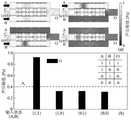
图4为不同输入状态下,声波通过(a)异或门和(b)非门对应的声压幅值空间分布及(c)O端的输出声压振幅。Fig. 4 shows the spatial distribution of sound pressure amplitude corresponding to (a) XOR gate and (b) NOT gate and (c) the output sound pressure amplitude of O terminal under different input states.
图5为不同输入状态下,声波通过或门对应的声压幅值空间分布及O端的输出声压振幅。Figure 5 shows the spatial distribution of the sound pressure amplitude corresponding to the sound wave passing through the OR gate and the output sound pressure amplitude of the O terminal under different input states.
图6为不同输入状态下,声波通过(a)与逻辑门产生的声压空间分布及(b)O端的输出声压振幅;Figure 6 shows the spatial distribution of sound pressure generated by sound waves passing through (a) AND logic gates and the output sound pressure amplitude of (b) O terminal under different input states;
图7逻辑门工作频带:(a)或逻辑门,(b)异或逻辑门,(c)非逻辑门,(d)与逻辑门。Figure 7 Logic gate operating frequency band: (a) OR logic gate, (b) XOR logic gate, (c) non-logic gate, (d) AND logic gate.
图8为不同输入状态下,声波通过(a)或非门对应的声压幅值空间分布及(b)O端的输出声压振幅。Figure 8 shows the spatial distribution of the sound pressure amplitude corresponding to (a) the NOR gate and (b) the output sound pressure amplitude of the O terminal when the sound wave passes through (a) the NOR gate under different input states.
图9为不同输入状态下,声波通过(a)与非门对应的声压幅值空间分布及(b)O端的输出声压振幅。Fig. 9 shows the spatial distribution of the sound pressure amplitude corresponding to the (a) NAND gate and (b) the output sound pressure amplitude of the O terminal when the sound wave passes through (a) the NAND gate under different input states.
图中:In the picture:
1-第一相控单元,2-第二相控单元,3-隔层,4-亥姆霍兹谐振腔,5-第三相控单元。1-first phase control unit, 2-second phase control unit, 3-spacer, 4-Helmholtz resonant cavity, 5-third phase control unit.
具体实施方式detailed description
下面结合附图以及具体实施例对本发明作进一步的说明,但本发明的保护范围并不限于此。The present invention will be further described below in conjunction with the accompanying drawings and specific embodiments, but the protection scope of the present invention is not limited thereto.
本发明所述的声逻辑门是由矩形刚性固体与两个相控单元组成的三端口波导结构。包括两个相控单元,即第一相控单元1、第二相控单元2,每一个相控单元均为一个具有独立入口的空腔,内部均有两排相对设置的亥姆霍兹谐振腔4,每一排亥姆霍兹谐振腔4的数量均大于等于两个;两个相控单元并排设置、且中间间隔隔层3;每两个相控单元出口与所述声逻辑门的出口相连通、且在连接处形成谐振区域;所述声逻辑门的出口与所述隔层3相对设置、且宽度d与隔层3的宽度相同,d取声波波长的十分之一。声逻辑门的材质为机玻璃、塑料、金属材料中的一种,例如环氧树脂、铁、铝、铜等。The acoustic logic gate of the invention is a three-port waveguide structure composed of a rectangular rigid solid and two phase control units. It includes two phase control units, namely the first
实施例1:Example 1:
如图1所示的实施例,所述声逻辑门中,两个相控单元的结构参数不同,能够实现“异或”和“非”的逻辑控制。具体的,所述第一相控单元1中每一个亥姆霍兹谐振腔4的结构参数为:亥姆霍兹谐振腔4的长为l=0.125λ,宽为w2=0.029λ,开口长度为l1=0.015λ,壁厚为w3=0.005λ,两排相对设置的亥姆霍兹谐振腔4之间的间距w1=0.022λ;第二相控单元2中每一个亥姆霍兹谐振腔4的结构参数为:亥姆霍兹谐振腔4的长为l=0.125λ,宽为w2=0.0055λ,开口长度为l1=0.015λ,壁厚为w3=0.005λ,两排相对设置的亥姆霍兹谐振腔4之间的间距w1=0.069λ;谐振区域的长度为d1=0.055λ;其中λ为入射声波的波长。In the embodiment shown in FIG. 1 , in the acoustic logic gate, the structural parameters of the two phase control units are different, and logic control of "exclusive OR" and "not" can be realized. Specifically, the structural parameters of each
第一相控单元1与第二相控单元2中输出的声波的相位差为π;图4为不同输入状态下,声波通过本实施例的所述声逻辑门产生的声压幅值空间分布以及输出O端的声压振幅,所实现的“异或”和“非”逻辑控制。如图4(a)所示,当两束声波同时入射到端口A和B,即输入逻辑值为{1,1},基于相位干涉相消机制,输出的声压幅值低于阈值,对应输出逻辑值为{0};当只有一束声波入射到端口A或B,即输入逻辑值为{1,0}或{0,1},输出的声压幅值高于阈值,对应输出逻辑值为{1};当没有声波入射到端口A和B,即输入逻辑值为{0,0},输出的声压幅值低于阈值,对应输出逻辑值为{0}。因此输入信号与输出信号之前的对应关系构成如表格所示的“异或”逻辑真值表。从而实现了“异或”逻辑功能。在此基础上,将入射端口B设置为有声波入射的恒定控制端口。如图4(b)所示,当有声波入射到端口A,即输入逻辑值为{1},输出的声压幅值低于阈值,对应输出逻辑值为{0};当没有声波入射到端口A,即输入逻辑值为{0},输出的声压幅值高与阈值,对应输出逻辑值为{1},从而实现了“非”逻辑功能。The phase difference of the sound waves output in the first
实施例2:Example 2:
如图2所示,所述声逻辑门中两个相控单元的的结构参数相同,能够实现“或”的逻辑控制。所述第一相控单元1与第二相控单元2中每一个亥姆霍兹谐振腔4的结构参数为:亥姆霍兹谐振腔4的长为l=0.125λ,宽为w2=0.0055λ,开口长度为l1=0.015λ,壁厚为壁厚为w3=0.005λ,两排相对设置的亥姆霍兹谐振腔4之间的间距w1=0.069λ;谐振区域的长度为d1=0.055λ。As shown in FIG. 2 , the structural parameters of the two phase control units in the acoustic logic gate are the same, which can realize "OR" logic control. The structural parameters of each
在第一相控单元1与第二相控单元2中输出的声波的相位差为0;图5为不同输入状态下,声波通过“或”声逻辑门产生的声压幅值空间分布以及输出O端的声压振幅。从图5中可以看出,当两束声波同时入射到端口A和B,即输入逻辑值为{1,1},基于相位干涉增强机制,输出O端的声压幅值高于阈值,对应输出逻辑值为{1};当只有一束声波入射到端口A或B,即输入逻辑值为{1,0}或{0,1},对应输出逻辑值也为{1};当没有声波入射到端口A和B,即输入逻辑值为{0,0},输出的声压幅值低于阈值,对应输出逻辑值为{0}。因此输入信号与输出信号间的对应关系构成如表格所示的“或”逻辑真值表,从而实现了或逻辑功能。The phase difference of the sound waves output in the first
实施例3:Example 3:
如图3所示,本实施例中的声逻辑门是在实施例2中的“或”逻辑门的基础上改进而来,将实施例2中声逻辑门中的隔层3替换为第三相控单元5,能够实现“与”的逻辑控制。所述第三相控单元5为一个具有独立入口的空腔,内部均有两排相对设置的亥姆霍兹谐振腔4,每一排亥姆霍兹谐振腔4的数量均大于等于两个,第三相控单元5的出口与谐振区域相通。As shown in Figure 3, the acoustic logic gate in this embodiment is improved on the basis of the "or" logic gate in
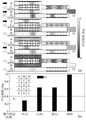
所述第三相控单元5中亥姆霍兹谐振腔4长和宽分别为l=0.125λ,w2=0.034λ,内腔长度l2为0.065λ,间距w1均取为0.012λ,开口长度为l1=0.015λ,壁厚为w3=0.005λ;所述第一相控单元1与第二相控单元2中的结构参数均相同,每一个亥姆霍兹谐振腔4的结构参数为:亥姆霍兹谐振腔4的长为l=0.125λ,宽为w2=0.0055λ,开口长度为l1=0.015λ,壁厚为w3=0.005λ,第三相控单元5的宽度w=d,两排相对设置的亥姆霍兹谐振腔4之间的间距w1=0.069λ;谐振区域的长度为d1=0.0055λ。The length and width of the Helmholtz
在第三相控单元5与第一相控单元1、第二相控单元2中输出的声波的相位差均为π;图6为不同输入状态下,声波通过逻辑“与”门产生的声压空间分布及O端的输出声压振幅,其中C端口设置为有声波入射的恒定声信号控制端口。从图6的结果可以看出,当有两束声波同时入射到端口A和B,即输入逻辑值为{1,1},输出的声压高于阈值,对应输出逻辑值为{1};当只有一束声波入射到端口A或B,即输入逻辑值为{1,0}或{0,1},输出的声压低于阈值,对应输出逻辑值为{0};当没有声波入射到端口A和B,即输入逻辑值为{0,0},对应输出逻辑值也为{0}。因此输入信号与输出信号之前的对应关系构成如表格所示的“与”逻辑真值表,从而实现了“与”逻辑功能。The phase difference of the sound waves output in the third
图7(a)-(d)分别显示逻辑或门、异或门、非门和与门在不同输入状态对应的输出端声压幅值。从图7(a)-(c)可以看出,在频率范围3140Hz-3840Hz,声逻辑门均能实现“或”、“异或”及“非”逻辑功能,其工作带宽可达700Hz,带宽比约为0.2。此外,如图7(d),在频率范围3270-3880Hz内,输入逻辑值为{1,1}对应的输出声压幅值高与阈值,而其它输入态对应的输出声压幅值低于阈值,从而实现了“与”逻辑功能,其工作带宽可达610Hz,带宽比约为0.18。Figure 7(a)-(d) respectively show the sound pressure amplitudes at the output terminals of logic OR gate, XOR gate, NOT gate and AND gate in different input states. From Figure 7(a)-(c), it can be seen that in the frequency range of 3140Hz-3840Hz, the acoustic logic gates can realize the logic functions of "or", "exclusive or" and "not", and their working bandwidth can reach 700Hz. The ratio is about 0.2. In addition, as shown in Figure 7(d), in the frequency range of 3270-3880Hz, the output sound pressure amplitude corresponding to the input logic value {1,1} is higher than the threshold, while the output sound pressure amplitude corresponding to other input states is lower than Threshold, thereby realizing the "AND" logic function, its working bandwidth can reach 610Hz, and the bandwidth ratio is about 0.18.
实施例4Example 4
所述实施例2所述的“或”声逻辑门的出口与实施例1所述的“非”声逻辑门的第二相控单元2的入口相连通,实施例1所述的“非”声逻辑门的第一相控单元1中的入口段有与实施例2所述的“或”声逻辑门长度相等的声道。图8为不同输入状态下,声波通过逻辑“或非”门产生的声压空间分布及O端的输出声压振幅,其中C端口设置为有声波入射的恒定声信号控制端口。从图8的结果可以看出,当有两束声波同时入射到端口A和B,即输入逻辑值为{1,1},输出的声压低于阈值,对应输出逻辑值为{0};当只有一束声波入射到端口A或B,即输入逻辑值为{1,0}或{0,1},输出的声压也低于阈值,对应输出逻辑值也为{0};当没有声波入射到端口A和B,即输入逻辑值为{0,0},对应输出逻辑值为{1}。因此输入信号与输出信号之前的对应关系构成如表格所示的“或非”逻辑真值表,从而实现了“或非”逻辑功能。The outlet of the "OR" acoustic logic gate described in
实施例5Example 5
所述实施例3所述的“与”声逻辑门的出口与实施例1所述的“非”声逻辑门的第二相控单元2的入口相连通,实施例1所述的“非”声逻辑门的第一相控单元1中的入口段有与实施例2所述的“与”声逻辑门长度相等的声道。图9为不同输入状态下,声波通过逻辑“与非”门产生的声压空间分布及O端的输出声压振幅,其中C和D端口设置为有声波入射的恒定声信号控制端口。从图9的结果可以看出,当有两束声波同时入射到端口A和B,即输入逻辑值为{1,1},输出的声压低于阈值,对应输出逻辑值为{0};当只有一束声波入射到端口A或B,即输入逻辑值为{1,0}或{0,1},输出的声压高于阈值,对应输出逻辑值为{1};当没有声波入射到端口A和B,即输入逻辑值为{0,0},对应输出逻辑值也为{1}。因此输入信号与输出信号之前的对应关系构成如表格所示的“与非”逻辑真值表,从而实现了“与非”逻辑功能。The outlet of the "AND" acoustic logic gate described in
所述实施例为本发明的优选的实施方式,但本发明并不限于上述实施方式,在不背离本发明的实质内容的情况下,本领域技术人员能够做出的任何显而易见的改进、替换或变型均属于本发明的保护范围。The described embodiment is a preferred implementation of the present invention, but the present invention is not limited to the above-mentioned implementation, without departing from the essence of the present invention, any obvious improvement, replacement or modification that those skilled in the art can make Modifications all belong to the protection scope of the present invention.
Claims (9)
Translated fromChinesePriority Applications (1)
| Application Number | Priority Date | Filing Date | Title |
|---|---|---|---|
| CN201910446273.1ACN110299129B (en) | 2019-05-27 | 2019-05-27 | A Broadband Subwavelength Acoustic Logic Gate Based on Binary Phase Control Unit |
Applications Claiming Priority (1)
| Application Number | Priority Date | Filing Date | Title |
|---|---|---|---|
| CN201910446273.1ACN110299129B (en) | 2019-05-27 | 2019-05-27 | A Broadband Subwavelength Acoustic Logic Gate Based on Binary Phase Control Unit |
Publications (2)
| Publication Number | Publication Date |
|---|---|
| CN110299129A CN110299129A (en) | 2019-10-01 |
| CN110299129Btrue CN110299129B (en) | 2022-12-16 |
Family
ID=68027310
Family Applications (1)
| Application Number | Title | Priority Date | Filing Date |
|---|---|---|---|
| CN201910446273.1AActiveCN110299129B (en) | 2019-05-27 | 2019-05-27 | A Broadband Subwavelength Acoustic Logic Gate Based on Binary Phase Control Unit |
Country Status (1)
| Country | Link |
|---|---|
| CN (1) | CN110299129B (en) |
Families Citing this family (3)
| Publication number | Priority date | Publication date | Assignee | Title |
|---|---|---|---|---|
| CN113068106B (en)* | 2020-01-02 | 2021-10-26 | 南京大学 | Multifunctional acoustic device based on passive astronomical time symmetric acoustic system |
| CN113242037B (en)* | 2021-03-26 | 2024-04-09 | 江苏大学 | Broadband sound logic gate based on topological insulator |
| CN115662377B (en)* | 2022-10-17 | 2025-07-08 | 江苏大学 | Resonance unit of frequency modulation ultrathin, ultra-sparse and low-frequency silencing device and application thereof |
Family Cites Families (6)
| Publication number | Priority date | Publication date | Assignee | Title |
|---|---|---|---|---|
| JP2704196B2 (en)* | 1988-09-07 | 1998-01-26 | 国際電信電話 株式会社 | Unique word detector |
| US5138586A (en)* | 1991-05-29 | 1992-08-11 | Eastman Kodak Company | Acoustic logic circuits |
| US9190738B2 (en)* | 2010-04-11 | 2015-11-17 | Broadcom Corporation | Projected artificial magnetic mirror |
| CN103822702A (en)* | 2014-03-14 | 2014-05-28 | 北京理工大学 | Pulse signal conversion device for acquiring and synchronously triggering sound field measured data of ultrasonic phased array energy converter |
| CN104793286B (en)* | 2015-05-11 | 2017-10-03 | 中国科学院半导体研究所 | Phasmon all-optical logic gates based on open pore resonance coupling effect |
| CN107196645B (en)* | 2017-05-17 | 2020-06-12 | 广东科学技术职业学院 | Fluid-Solid Acoustic Logic AND-Gate Device Based on Phononic Crystal Ring Resonator |
- 2019
- 2019-05-27CNCN201910446273.1Apatent/CN110299129B/enactiveActive
Also Published As
| Publication number | Publication date |
|---|---|
| CN110299129A (en) | 2019-10-01 |
Similar Documents
| Publication | Publication Date | Title |
|---|---|---|
| CN110299129B (en) | A Broadband Subwavelength Acoustic Logic Gate Based on Binary Phase Control Unit | |
| Fu et al. | Controllably asymmetric beam splitting via gap-induced diffraction channel transition in dual-layer binary metagratings | |
| Gholamnejad et al. | Design and analysis of all-optical 4–2 binary encoder based on photonic crystal | |
| Askarian et al. | A novel proposal for all optical half-subtractor based on photonic crystals | |
| Shaik et al. | Single photonic crystal structure for realization of NAND and NOR logic functions by cascading basic gates | |
| US7570409B1 (en) | Radiation modulation by reflection from controlled composite material | |
| US20020146196A1 (en) | Optical switch having photonic crystal structure | |
| Serajmohammadi et al. | All optical NAND gate based on nonlinear photonic crystal ring resonator | |
| Liu et al. | A review of anomalous refractive and reflective metasurfaces | |
| Lan et al. | Acoustic multifunctional logic gates and amplifier based on passive parity-time symmetry | |
| Fakhruldeen et al. | Multiple inputs all-optical logic gates based on nanoring insulator-metal-insulator plasmonic waveguides | |
| Zuo et al. | Broadband acoustic logic gates in a circular waveguide with multiple ports | |
| CN113242037B (en) | Broadband sound logic gate based on topological insulator | |
| Soroosh et al. | Designing a compact photonic crystal decoder using graphene-SiO2 stack | |
| CN113156740B (en) | Composite structure of figure early-molar sequence multilayer dielectric medium and graphene | |
| Peng et al. | Reconfigurable frequency-selective acoustic coding metasurface for multifunctional wavefront manipulation | |
| US4378951A (en) | Traveling wave coupled type optical wave circulators | |
| CN116564268A (en) | Broadband sub-wavelength sound trigger based on multiport waveguide structure | |
| Shaik et al. | Investigation on phc based t-shaped waveguide as all-optical xor, not, or and and logic gates | |
| CN215376024U (en) | Composite structure of tuer-morse sequence multilayer dielectric and graphene | |
| CN110196468A (en) | A kind of all-optical diode structure based on non-linear microcavity coupled system | |
| Yang et al. | A design method of optical phased array with insufficient phase tuning range | |
| Ma et al. | A Switchable Absorption–Transmission Window Modulator Based on 1-D Magnetized Plasma Photonic Crystals | |
| Suryanto et al. | Finite element analysis of optical bistability in one-dimensional nonlinear photonic band gap structures with a defect | |
| Hu et al. | Ultra-compact 1× 8 channel terahertz wave power splitter |
Legal Events
| Date | Code | Title | Description |
|---|---|---|---|
| PB01 | Publication | ||
| PB01 | Publication | ||
| SE01 | Entry into force of request for substantive examination | ||
| SE01 | Entry into force of request for substantive examination | ||
| GR01 | Patent grant | ||
| GR01 | Patent grant |