CN110279447B - A combined spiral reinforced bone anchor - Google Patents
A combined spiral reinforced bone anchorDownload PDFInfo
- Publication number
- CN110279447B CN110279447BCN201910575421.XACN201910575421ACN110279447BCN 110279447 BCN110279447 BCN 110279447BCN 201910575421 ACN201910575421 ACN 201910575421ACN 110279447 BCN110279447 BCN 110279447B
- Authority
- CN
- China
- Prior art keywords
- anchor
- nail
- screw
- main body
- spiral
- Prior art date
- Legal status (The legal status is an assumption and is not a legal conclusion. Google has not performed a legal analysis and makes no representation as to the accuracy of the status listed.)
- Expired - Fee Related
Links
Images
Classifications
- A—HUMAN NECESSITIES
- A61—MEDICAL OR VETERINARY SCIENCE; HYGIENE
- A61B—DIAGNOSIS; SURGERY; IDENTIFICATION
- A61B17/00—Surgical instruments, devices or methods
- A61B17/04—Surgical instruments, devices or methods for suturing wounds; Holders or packages for needles or suture materials
- A61B17/0401—Suture anchors, buttons or pledgets, i.e. means for attaching sutures to bone, cartilage or soft tissue; Instruments for applying or removing suture anchors
- A—HUMAN NECESSITIES
- A61—MEDICAL OR VETERINARY SCIENCE; HYGIENE
- A61B—DIAGNOSIS; SURGERY; IDENTIFICATION
- A61B17/00—Surgical instruments, devices or methods
- A61B17/064—Surgical staples, i.e. penetrating the tissue
- A61B17/0642—Surgical staples, i.e. penetrating the tissue for bones, e.g. for osteosynthesis or connecting tendon to bone
- A—HUMAN NECESSITIES
- A61—MEDICAL OR VETERINARY SCIENCE; HYGIENE
- A61B—DIAGNOSIS; SURGERY; IDENTIFICATION
- A61B17/00—Surgical instruments, devices or methods
- A61B17/04—Surgical instruments, devices or methods for suturing wounds; Holders or packages for needles or suture materials
- A61B17/0401—Suture anchors, buttons or pledgets, i.e. means for attaching sutures to bone, cartilage or soft tissue; Instruments for applying or removing suture anchors
- A61B2017/0408—Rivets
- A—HUMAN NECESSITIES
- A61—MEDICAL OR VETERINARY SCIENCE; HYGIENE
- A61B—DIAGNOSIS; SURGERY; IDENTIFICATION
- A61B17/00—Surgical instruments, devices or methods
- A61B17/04—Surgical instruments, devices or methods for suturing wounds; Holders or packages for needles or suture materials
- A61B17/0401—Suture anchors, buttons or pledgets, i.e. means for attaching sutures to bone, cartilage or soft tissue; Instruments for applying or removing suture anchors
- A61B2017/044—Suture anchors, buttons or pledgets, i.e. means for attaching sutures to bone, cartilage or soft tissue; Instruments for applying or removing suture anchors with a threaded shaft, e.g. screws
- A—HUMAN NECESSITIES
- A61—MEDICAL OR VETERINARY SCIENCE; HYGIENE
- A61B—DIAGNOSIS; SURGERY; IDENTIFICATION
- A61B17/00—Surgical instruments, devices or methods
- A61B17/04—Surgical instruments, devices or methods for suturing wounds; Holders or packages for needles or suture materials
- A61B17/0401—Suture anchors, buttons or pledgets, i.e. means for attaching sutures to bone, cartilage or soft tissue; Instruments for applying or removing suture anchors
- A61B2017/0464—Suture anchors, buttons or pledgets, i.e. means for attaching sutures to bone, cartilage or soft tissue; Instruments for applying or removing suture anchors for soft tissue
Landscapes
- Health & Medical Sciences (AREA)
- Surgery (AREA)
- Life Sciences & Earth Sciences (AREA)
- Medical Informatics (AREA)
- Nuclear Medicine, Radiotherapy & Molecular Imaging (AREA)
- Engineering & Computer Science (AREA)
- Biomedical Technology (AREA)
- Heart & Thoracic Surgery (AREA)
- Rheumatology (AREA)
- Molecular Biology (AREA)
- Animal Behavior & Ethology (AREA)
- General Health & Medical Sciences (AREA)
- Public Health (AREA)
- Veterinary Medicine (AREA)
- Orthopedic Medicine & Surgery (AREA)
- Surgical Instruments (AREA)
Abstract
Description
Translated fromChinese技术领域technical field
本发明涉及一种医疗骨锚钉,更具体地说,涉及一种组合式螺旋强化型骨锚钉,尤其涉及一种肌腱损伤修复的微创缝合锚钉。The invention relates to a medical bone anchor, more particularly, to a combined helical reinforced bone anchor, in particular to a minimally invasive suture anchor for tendon injury repair.
背景技术Background technique
韧带、肌腱或其他软组织从其附着的骨骼完全或部分的分离是比较常见的损伤,部分的分离通常可通过保守治疗获得满意的效果,但完全的分离则需要手术治疗来完成软组织对骨的重新附着。缝合锚钉是一种外科手术中用于连接肌腱、韧带等软组织和骨的微型装置,可将损伤的肌腱残端固定到骨组织,以恢复肌腱的正常结构和关节功能,通过腱骨愈合达到最终固定的目的。Complete or partial detachment of a ligament, tendon, or other soft tissue from the bone to which it is attached is a relatively common injury. Partial detachment can usually be treated conservatively with satisfactory results, but complete detachment requires surgery to complete the soft-tissue reconstruction of the bone. attached. Suture anchor is a miniature device used to connect soft tissue and bone such as tendon and ligament in surgery. It can fix the injured tendon stump to the bone tissue to restore the normal structure and joint function of the tendon. final fixed purpose.
腱骨愈合的过程需要肌腱与骨端的粗糙面有一定的接触面积并有牢固的接触稳定性。因此,锚钉在骨内的固定强度,是手术成功的关键和基础。The process of tendon-bone healing requires a certain contact area and firm contact stability between the tendon and the rough surface of the bone end. Therefore, the fixation strength of the anchor in the bone is the key and foundation for the success of the operation.
传统的缝合锚钉主要由锚、孔眼和缝线三部分组成,且在锚钉的主体周围设有大小不一的螺纹结构或突出的翅形结构,通过旋转拧入或直接打入骨内,达到固定的目的。例如中国专利申请号CN201310098757.4公开的名称为一种用于软组织修复固定的多线孔锚钉、中国专利申请号CN201610013055.5公开的名称为一种骨科锁定螺钉、以及中国专利申请号CN201811551062.6公开的名称为骨科植入螺钉等专利申请案。然而,现有技术中的锚钉在使用时常会遇到以下问题:1、锚钉把持力弱,术中或术后常出现锚钉松动、拨出的情况,导致固定失效,此现象多发于骨量减少或骨质疏松的病例;2、锚钉植入骨内时,锚钉相互间需要保持一定距离,否则影响固定强度,而这限制了锚钉植入数量;3、一旦锚钉发生松动拔出后,就很难再原位植入,需重新在远离原位孔的位置植入锚钉,这不仅增加了操作难度,也严重影响术中固定的可靠性;4、锚钉固定时造成的骨质破坏较多。The traditional suture anchor is mainly composed of three parts: the anchor, the hole and the suture, and the main body of the anchor is provided with a thread structure of different sizes or a protruding fin structure, which can be screwed into the bone by rotation or directly driven into the bone. fixed purpose. For example, Chinese Patent Application No. CN201310098757.4 discloses a multi-hole anchor for soft tissue repair and fixation, Chinese Patent Application No. CN201610013055.5 discloses an orthopedic locking screw, and Chinese Patent Application No. CN201811551062. 6 Published patent applications for orthopaedic implant screws etc. However, the anchors in the prior art often encounter the following problems during use: 1. The anchors are weak in holding force, and the anchors are often loosened and pulled out during or after surgery, resulting in fixation failure. Cases of osteopenia or osteoporosis; 2. When the anchors are implanted in the bone, the anchors need to keep a certain distance from each other, otherwise the fixation strength will be affected, which limits the number of anchors implanted; 3. Once the anchors occur After loosening and pulling out, it is difficult to re-implant in situ, and it is necessary to re-implant the anchor at a position far from the in-situ hole, which not only increases the difficulty of operation, but also seriously affects the reliability of intraoperative fixation; 4. Anchor fixation More bone damage is caused.
针对上述问题,中国专利号CN201080014327.4,公开了名称为:锁定螺旋锚固装置的申请案,其涉及一种骨螺钉,包括近侧头部,该近侧头部有中心轴线和外螺纹,该外螺纹有节距p,用于与骨板孔锁定接合;以及第一轴,第一轴从近侧头部向远侧延伸,并有螺旋形形状,具有节距P和螺旋轴线。近侧头部和第一轴可旋转地相互连接,这样,轴能够绕它的轴线相对于近侧头部旋转。又如中国专利申请号CN201710033790.7,公开了名称为:一种固定于松质骨骨折的螺旋钉的申请案,其分为两部分,分别为螺旋钉钉体和钉尾结构。钉体为螺旋形弹簧样结构,前方尖锐,螺旋钉钉体的横截面为圆形。螺旋钉的螺距及钉体横截面可根据材料及力学性能做适当更改;螺旋钉的钉尾为空心外六角形钉尾,螺旋钉钉体自然旋转与钉尾自然融合。钉尾空心部位有螺纹,用于安放与之配套的六角拧入扳手。六角拧入扳手为中空。其内有与钉尾空心处螺纹匹配的螺栓,螺栓也为空心,用于容纳导航克氏针。六角拧入扳手与钉尾六角形钉尾相匹配。如钉尾为U形,当钉体拧入脊柱椎体后可安放与之相匹配的圆棒,用于脊柱前路固定。上述专利申请案将骨螺钉设计为螺旋结构,在一定程度上解决了传统螺纹结构或突出翅形结构的锚钉植入位置和数量受限、对骨质破坏较多等不足,但该骨螺钉植入部分为螺旋细丝状结构,其自身锚固强度较低,在骨螺钉靠近骨板或缝合线的一端变形自由度较大,影响了其锚固强度;并且其植入部分的把持力由外向内是变化的,一般来说,内侧的把持力更大,而靠外侧的把持力因螺旋细丝结构的局部强度低而降低,因此在使用过程中容易在骨骼靠外侧位置产松动,尤其对于骨量减少或骨质疏松的患者,锚固强度还有待进一步提高。In view of the above problems, Chinese Patent No. CN201080014327.4 discloses an application entitled: Locking Helical Anchoring Device, which relates to a bone screw, including a proximal head, the proximal head has a central axis and an external thread, the The external threads have a pitch P for locking engagement with the plate hole; and a first shaft extending distally from the proximal head and having a helical shape with a pitch P and a helical axis. The proximal head and the first shaft are rotatably interconnected such that the shaft is rotatable about its axis relative to the proximal head. Another example is the Chinese Patent Application No. CN201710033790.7, which discloses an application entitled: a screw nail fixed to a cancellous bone fracture, which is divided into two parts, a screw nail body and a nail tail structure. The nail body is a helical spring-like structure with a sharp front, and the cross section of the helical nail body is circular. The pitch of the screw and the cross section of the screw body can be appropriately changed according to the material and mechanical properties; the screw tail of the screw screw is a hollow outer hexagonal screw tail, and the natural rotation of the screw body and the natural fusion of the screw tail. The hollow part of the nail tail is threaded, which is used to place the matching hexagonal screw-in wrench. The hexagonal screw-in wrench is hollow. There are bolts matching the threads in the hollow of the nail tail, and the bolts are also hollow to accommodate the navigation K-wire. The hex screw-in wrench mates with the nail tail hex tail. If the nail tail is U-shaped, when the nail body is screwed into the vertebral body of the spine, a matching round rod can be placed for anterior spinal fixation. The above patent application designs the bone screw as a helical structure, which to a certain extent solves the shortcomings of the traditional threaded structure or protruding wing-shaped anchors, such as the limited implantation position and number, and the damage to the bone. The implanted part is a helical filament structure, and its own anchoring strength is low, and the deformation freedom of the end of the bone screw close to the bone plate or suture is large, which affects its anchoring strength; and the holding force of the implanted part is from the outside. The inner side varies. Generally speaking, the inner side has a greater holding force, while the outer side is reduced due to the low local strength of the helical filament structure. Therefore, it is easy to loosen the bones on the outer side during use, especially for In patients with osteopenia or osteoporosis, the anchoring strength needs to be further improved.
发明内容SUMMARY OF THE INVENTION
1.发明要解决的技术问题1. The technical problem to be solved by the invention
本发明的目的在于克服现有骨锚钉存在把持力弱等不足,提供一种组合式螺旋强化型骨锚钉,采用本发明的技术方案,通过将锚钉和螺旋钉有机结合,利用螺旋钉提供锚钉在骨内的把持力,把持力强,术中或术后不易出现松动等情况,并且可有效分散应力,对骨质破坏小;另外,锚钉植入距离和数量所受局限性小,锚钉植入密度可更高,尤其适合骨质疏松患者的肌腱缝合固定;而且锚钉出现松动通过更换直径更大的螺旋钉即可在原位重新植入,操作更加简单灵活。The purpose of the present invention is to overcome the shortcomings of the existing bone anchors such as weak holding force, and to provide a combined helical reinforced bone anchor. By using the technical solution of the present invention, the anchor and the screw are organically combined, and the screw is used. Provides the holding force of the anchor in the bone. The holding force is strong, and it is not easy to loosen during or after the operation, and it can effectively disperse the stress and cause little damage to the bone. In addition, the distance and quantity of the anchor implant are limited. It is small, and the implantation density of the anchor can be higher, which is especially suitable for tendon suture fixation in patients with osteoporosis; and if the anchor becomes loose, it can be re-implanted in situ by replacing the screw with a larger diameter, and the operation is simpler and more flexible.
2.技术方案2. Technical solutions
为达到上述目的,本发明提供的技术方案为:In order to achieve the above object, the technical scheme provided by the invention is:
本发明的一种组合式螺旋强化型骨锚钉,包括锚钉和螺旋钉两部分,其中,所述的锚钉包括锚钉头部和锚钉主体,所述的锚钉头部一体设于锚钉主体的前端,且锚钉头部的宽度大于锚钉主体的宽度,所述的锚钉主体的尾部设有线孔;所述的螺旋钉包括螺旋状主体,螺旋状主体的前部具有尖锐的钉头,后部具有用于螺旋钉旋转植入的钉尾;所述的螺旋钉的内径大于锚钉主体的宽度、小于锚钉头部的宽度,所述的螺旋钉在植入时套于锚钉主体上,且螺旋钉的前部抵在锚钉头部。A combined screw-reinforced bone anchor of the present invention includes two parts: an anchor and a screw, wherein the anchor includes an anchor head and an anchor main body, and the anchor head is integrally provided on the The front end of the main body of the anchor, and the width of the head of the anchor is greater than the width of the main body of the anchor, and the tail of the main body of the anchor is provided with a wire hole; The screw head is provided with a screw tail for rotating and implanting the screw at the rear; the inner diameter of the screw screw is larger than the width of the main body of the anchor and smaller than the width of the head of the anchor, and the screw is sleeved during implantation. on the main body of the anchor, and the front part of the screw abuts the head of the anchor.
更进一步地,所述的锚钉为扁平状结构,且锚钉头部尖锐。Further, the anchor has a flat structure, and the head of the anchor is sharp.
更进一步地,所述的锚钉由医用金属材料或可吸收材料制成。Further, the anchor is made of medical metal material or absorbable material.
更进一步地,所述的线孔在锚钉主体的尾部设有2~3个。Further, 2-3 of the wire holes are provided at the tail of the anchor main body.
更进一步地,所述的螺旋钉表面光滑或带有倒刺结构。Further, the surface of the screw nail is smooth or has a barb structure.
本发明的一种组合式螺旋强化型骨锚钉,包括锚钉和螺旋钉两部分,其中,所述的锚钉包括锚钉头部和锚钉主体,所述的锚钉头部一体设于锚钉主体的前端,所述的锚钉主体的尾部设有线孔,所述的锚钉主体上设有沿长度方向延伸的穿钉孔;所述的螺旋钉包括螺旋状主体,螺旋状主体的前部具有尖锐的钉头,后部具有用于螺旋钉旋转植入的钉尾;所述的螺旋钉的内径大于锚钉主体的穿钉孔两侧边壁厚尺寸,所述的螺旋钉在植入时,螺旋钉一侧穿入穿钉孔套于锚钉主体的对应侧边上,且螺旋钉的前部抵在穿钉孔的前部。A combined screw-reinforced bone anchor of the present invention includes two parts: an anchor and a screw, wherein the anchor includes an anchor head and an anchor main body, and the anchor head is integrally provided on the The front end of the anchor main body, the tail of the anchor main body is provided with a wire hole, and the anchor main body is provided with a nail penetration hole extending along the length direction; The front part has a sharp nail head, and the rear part has a nail tail for rotating and implanting the screw nail; the inner diameter of the screw nail is larger than the wall thickness size of the two sides of the nail penetration hole of the anchor main body, and the screw nail is located in the hole. During implantation, one side of the helical nail is inserted into the nail-penetrating hole and is sleeved on the corresponding side of the anchor main body, and the front part of the helical nail is abutted against the front part of the nail-penetrating hole.
更进一步地,所述的锚钉为扁平状结构,且锚钉头部尖锐;所述的螺旋钉表面光滑或带有倒刺结构。Further, the anchor has a flat structure, and the head of the anchor is sharp; the surface of the screw is smooth or has a barb structure.
更进一步地,所述的锚钉由医用金属材料或可吸收材料制成。Further, the anchor is made of medical metal material or absorbable material.
更进一步地,所述的锚钉主体的穿钉孔两侧边各设有一螺旋钉。Further, a screw is provided on both sides of the nail penetration hole of the anchor main body.
更进一步地,所述的线孔在锚钉主体的尾部设有2~3个。Further, 2-3 of the wire holes are provided at the tail of the anchor main body.
3.有益效果3. Beneficial effects
采用本发明提供的技术方案,与已有的公知技术相比,具有如下显著效果:Adopting the technical scheme provided by the present invention, compared with the existing known technology, has the following remarkable effects:
(1)本发明的一种组合式螺旋强化型骨锚钉,其通过将锚钉和螺旋钉有机结合,在锚钉打入预钻的骨孔中后,从锚钉后部拧入螺旋钉,利用螺旋钉提供锚钉在骨内的把持力,把持力强,增强松质骨的抓握力,同时可有效的分散应力,达到锚钉在骨内的初始稳定,防止锚钉的松动和滑脱,有效地促进腱骨愈合;(1) A combined screw-reinforced bone anchor of the present invention, by organically combining the anchor and the screw, after the anchor is driven into the pre-drilled bone hole, the screw is screwed into the back of the anchor , using the screw to provide the anchor's holding force in the bone, the holding force is strong, and the grasping force of the cancellous bone can be enhanced. At the same time, it can effectively disperse the stress, achieve the initial stability of the anchor in the bone, and prevent the anchor from loosening and slipping. , effectively promote tendon and bone healing;
(2)本发明的一种组合式螺旋强化型骨锚钉,其锚钉为扁平状结构,且锚钉头部尖锐,便于锚钉打入预钻的骨孔中,且锚钉制作简单方便;并且,因锚钉为较薄的片状结构,以及螺旋钉为截面直径较小的螺旋结构,对周围骨质破坏少,能够基本保留周围骨质的连续性和强度,因此锚钉植入距离和数量所受局限性小,相互间无需保持较大距离,即便互相接触也不影响固定强度,锚钉植入密度可更高,尤其适合骨质疏松患者的肌腱缝合固定;(2) A combined spiral reinforced bone anchor of the present invention has a flat structure and a sharp head, which is convenient for the anchor to be driven into the pre-drilled bone hole, and the anchor is simple and convenient to manufacture. ; And, because the anchor is a thin sheet structure, and the screw is a helical structure with a small cross-sectional diameter, it has less damage to the surrounding bone and can basically retain the continuity and strength of the surrounding bone, so the anchor is implanted. The limitation of distance and quantity is small, and there is no need to maintain a large distance between each other. Even if they are in contact with each other, the fixation strength will not be affected.
(3)本发明的一种组合式螺旋强化型骨锚钉,其锚钉出现松动后,通过更换直径更大的螺旋钉即可在原位重新植入,无需改变植入部位,甚至可以作为其他锚钉固定失败后的补救措施,操作更加简单灵活。(3) A combined spiral reinforced bone anchor of the present invention can be re-implanted in situ by replacing the screw with a larger diameter after the anchor is loose, without changing the implantation site, and can even be used as a The remedial measures after the failure of other anchors, the operation is simpler and more flexible.
附图说明Description of drawings
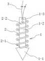
图1为本发明实施例1的一种组合式螺旋强化型骨锚钉的主视结构示意图;1 is a schematic front view of a combined spiral-reinforced bone anchor according to
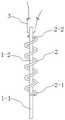
图2为本发明实施例1的一种组合式螺旋强化型骨锚钉的侧视结构示意图;2 is a schematic side view of the structure of a combined spiral-reinforced bone anchor according to
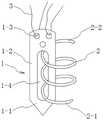
图3为本发明实施例2的一种组合式螺旋强化型骨锚钉的主视结构示意图。FIG. 3 is a schematic front view of the structure of a combined spiral-reinforced bone anchor according to
示意图中的标号说明:Description of the labels in the diagram:
1、锚钉;1-1、锚钉头部;1-2、锚钉主体;1-3、线孔;1-4、穿钉孔;2、螺旋钉;2-1、钉头;2-2、钉尾;3、缝线。1. Anchor; 1-1, Anchor head; 1-2, Anchor body; 1-3, Line hole; 1-4, Nail hole; 2, Spiral nail; 2-1, Nail head; 2 -2. Nail tail; 3. Suture.
具体实施方式Detailed ways
为进一步了解本发明的内容,结合附图和实施例对本发明作详细描述。In order to further understand the content of the present invention, the present invention will be described in detail with reference to the accompanying drawings and embodiments.
实施例1Example 1
结合图1和图2所示,本实施例的一种组合式螺旋强化型骨锚钉,包括锚钉1和螺旋钉2两部分,其中,锚钉1包括锚钉头部1-1和锚钉主体1-2,锚钉头部1-1一体设于锚钉主体1-2的前端,锚钉头部1-1与锚钉主体1-2一体成型,且锚钉头部1-1的宽度大于锚钉主体1-2的宽度,在锚钉头部1-1与锚钉主体1-2连接位置形成台阶结构,锚钉主体1-2的尾部设有线孔1-3,用于穿设缝线3。锚钉1优选采用扁平状结构,且锚钉头部1-1尖锐,便于锚钉1打入预钻的骨孔中,且锚钉1制作简单方便。As shown in FIG. 1 and FIG. 2 , a combined helical reinforced bone anchor of this embodiment includes an
螺旋钉2包括螺旋状主体,螺旋状主体的前部具有尖锐的钉头2-1,便于螺旋钉2植入,后部具有用于螺旋钉2旋转植入的钉尾2-2,钉尾2-2部分可采用专利CN201080014327.4或CN201710033790.7中的类似结构,便于利用专用工具进行旋转植入;也可在钉尾2-2部分参考专利CN200980155954.7中的“螺旋圈”在钉尾2-2内侧设计出与专用工具相匹配的凸起或凹槽,以利用凸起或凹槽的配合实现螺旋钉2旋转拧入。钉尾2-2的具体结构在图中未示出。螺旋钉2的螺距及钉体横截面可根据材料及力学性能而定,其截面优选采用圆形。螺旋钉2表面光滑,便于螺旋钉植入。在一种实施方式中,也可使螺旋钉2表面带有倒刺结构,以增强螺旋钉2与松质骨的抓握力。螺旋钉2的内径大于锚钉主体1-2的宽度、小于锚钉头部1-1的宽度,螺旋钉2在植入时套于锚钉主体1-2上,且螺旋钉2的前部抵在锚钉头部1-1,以提供锚钉1与松质骨之间的把持力。The
在本实施例中,锚钉1和螺旋钉2均可由把持力好、易于植入的医用金属材料制成,例如钛、钛合金和钴铬合金等,便于通过X线评估锚固质量。锚钉1还可采用可吸收材料制成,例如聚羟基乙酸、聚左旋乳酸和消旋聚乳酸聚乙醇酸聚合物等,该类材料制成的锚钉1更适合小儿使用。另外,线孔1-3在锚钉主体1-2的尾部优选设有2~3个,可在术中按需要穿1~3根缝线3,甚至更多,方便肌腱缝合。In this embodiment, the
如图1和图2所示,本实施例的一种组合式螺旋强化型骨锚钉,使用时,先将锚钉1打入预钻的骨孔中,然后从锚钉1尾部拧入用螺旋钉2,利用螺旋钉2来与骨组织牢固结合,使锚钉1内螺旋钉2固定在骨孔内。由于螺旋钉2为直径较小的螺旋结构,对周围骨质破坏少,植入后仍基本保留周围骨质的连续性和强度,所以螺旋钉2的把持力更强,并且锚钉1与螺旋钉2的作用点位于螺旋钉2植入骨组织的内部,最大化地发挥了螺旋钉2的锚固作用,使得锚钉1牢固结合在骨组织内,增强了松质骨的抓握力,并且螺旋钉2可有效的分散应力,达到锚钉在骨内的初始稳定,防止锚钉的松动和滑脱,有效地促进腱骨愈合。另外,由于锚钉1为较薄的片状结构,以及螺旋钉2为截面直径较小的螺旋结构,对周围骨质破坏少,因此锚钉植入距离和数量所受局限性小,相互间无需保持较大距离,使用时不必刻意保持一定距离,即便互相接触也不影响固定强度,锚钉植入密度可更高,尤其适合骨质疏松患者的肌腱缝合固定,有效克服了目前临床上锚钉容易松动及骨质破坏多等缺点。并且,采用上述骨锚钉结构,锚钉出现松动后,通过更换直径更大的螺旋钉即可在原位重新植入或略微错位重新植入,无需改变植入部位,甚至可以作为其他锚钉固定失败后的补救措施,操作更加简单灵活,适于临床推广使用。As shown in Fig. 1 and Fig. 2, a combined screw-reinforced bone anchor of this embodiment, when in use, first drive the
实施例2Example 2
结合图3所示,本实施例的一种组合式螺旋强化型骨锚钉,其使用原理与实施例1类似,包括锚钉1和螺旋钉2两部分,其中,锚钉1包括锚钉头部1-1和锚钉主体1-2,锚钉头部1-1一体设于锚钉主体1-2的前端,锚钉头部1-1与锚钉主体1-2一体成型,锚钉主体1-2的尾部设有便于缝线3穿入的线孔1-3,锚钉主体1-2上设有沿长度方向延伸的穿钉孔1-4,该穿钉孔1-4优选为腰形孔结构。锚钉1优选采用扁平状结构,且锚钉头部1-1尖锐,便于锚钉1打入预钻的骨孔中,且锚钉1制作简单方便。As shown in FIG. 3 , a combined spiral-reinforced bone anchor in this embodiment has a similar use principle to that in
螺旋钉2包括螺旋状主体,螺旋状主体的前部具有尖锐的钉头2-1,便于螺旋钉2植入,后部具有用于螺旋钉2旋转植入的钉尾2-2,钉尾2-2结构与实施例1相同,可采用专利CN201080014327.4或CN201710033790.7中的类似结构也可在钉尾2-2部分参考专利CN200980155954.7中的“螺旋圈”在钉尾2-2内侧设计出与专用工具相匹配的凸起或凹槽。螺旋钉2的螺距及钉体横截面可根据材料及力学性能而定,其截面优选采用圆形。螺旋钉2表面光滑或带有倒刺结构均可。螺旋钉2的内径大于锚钉主体1-2的穿钉孔1-4两侧边壁厚尺寸,螺旋钉2在植入时,螺旋钉2一侧穿入穿钉孔1-4套于锚钉主体1-2的对应侧边上,且螺旋钉2的前部抵在穿钉孔1-4的前部,以提供锚钉1与松质骨之间的把持力。为了提高锚钉1的抓握力和受力平衡性,可在锚钉主体1-2的穿钉孔1-4两侧边各设有一螺旋钉2,进一步提高了骨锚钉的固定强度和受力稳定性。The
在本实施例中,锚钉1和螺旋钉2均可由把持力好、易于植入的医用金属材料制成,例如钛、钛合金和钴铬合金等,便于通过X线评估锚固质量。锚钉1还可采用可吸收材料制成,例如聚羟基乙酸、聚左旋乳酸和消旋聚乳酸聚乙醇酸聚合物等,该类材料制成的锚钉1更适合小儿使用。另外,线孔1-3在锚钉主体1-2的尾部优选设有2~3个,可在术中按需要穿1~3根缝线3,甚至更多,方便肌腱缝合。In this embodiment, the
如图3所示,本实施例的一种组合式螺旋强化型骨锚钉,使用时,首先将锚钉1击入预钻的骨孔中,然后从锚钉1尾部偏向一侧拧入螺旋钉2,使螺旋钉2的钉头2-1旋入锚钉1中部的穿钉孔1-4内,直至螺旋钉2前部与锚钉1前部相抵,形成图3所示状态。根据需要,可在锚钉1尾部偏向另一侧再拧入一颗螺旋钉2,以提高骨锚钉的固定强度和受力稳定性。由于螺旋钉2为直径较小的螺旋结构,对周围骨质破坏少,植入后仍基本保留周围骨质的连续性和强度,所以螺旋钉2的把持力更强,并且锚钉1与螺旋钉2的作用点位于螺旋钉2植入骨组织的内部,最大化地发挥了螺旋钉2的锚固作用,使得锚钉1牢固结合在骨组织内,增强了松质骨的抓握力,并且螺旋钉2可有效的分散应力,达到锚钉在骨内的初始稳定,防止锚钉的松动和滑脱,有效地促进腱骨愈合。另外,由于锚钉1为较薄的片状结构,以及螺旋钉2为截面直径较小的螺旋结构,对周围骨质破坏少,因此锚钉植入距离和数量所受局限性小,相互间无需保持较大距离,使用时不必刻意保持一定距离,即便互相接触也不影响固定强度,锚钉植入密度可更高,尤其适合骨质疏松患者的肌腱缝合固定,有效克服了目前临床上锚钉容易松动及骨质破坏多等缺点。并且,采用上述骨锚钉结构,锚钉出现松动后,通过更换直径更大的螺旋钉即可在原位重新植入或略微错位重新植入,无需改变植入部位,甚至可以作为其他锚钉固定失败后的补救措施,操作更加简单灵活,适于临床推广使用。As shown in Fig. 3, a combined spiral reinforced bone anchor of this embodiment, when in use, first drive the
以上示意性地对本发明及其实施方式进行了描述,该描述没有限制性,附图中所示的也只是本发明的实施方式之一,实际的结构并不局限于此。所以,如果本领域的普通技术人员受其启示,在不脱离本发明创造宗旨的情况下,不经创造性地设计出与该技术方案相似的结构方式及实施例,均应属于本发明的保护范围。The present invention and its embodiments have been described above schematically, and the description is not restrictive, and what is shown in the accompanying drawings is only one of the embodiments of the present invention, and the actual structure is not limited thereto. Therefore, if those of ordinary skill in the art are inspired by it, and without departing from the purpose of the present invention, creatively design structures and embodiments similar to this technical solution, all should belong to the protection scope of the present invention. .
Claims (5)
Translated fromChinesePriority Applications (1)
| Application Number | Priority Date | Filing Date | Title |
|---|---|---|---|
| CN201910575421.XACN110279447B (en) | 2019-06-28 | 2019-06-28 | A combined spiral reinforced bone anchor |
Applications Claiming Priority (1)
| Application Number | Priority Date | Filing Date | Title |
|---|---|---|---|
| CN201910575421.XACN110279447B (en) | 2019-06-28 | 2019-06-28 | A combined spiral reinforced bone anchor |
Publications (2)
| Publication Number | Publication Date |
|---|---|
| CN110279447A CN110279447A (en) | 2019-09-27 |
| CN110279447Btrue CN110279447B (en) | 2022-05-06 |
Family
ID=68019556
Family Applications (1)
| Application Number | Title | Priority Date | Filing Date |
|---|---|---|---|
| CN201910575421.XAExpired - Fee RelatedCN110279447B (en) | 2019-06-28 | 2019-06-28 | A combined spiral reinforced bone anchor |
Country Status (1)
| Country | Link |
|---|---|
| CN (1) | CN110279447B (en) |
Families Citing this family (3)
| Publication number | Priority date | Publication date | Assignee | Title |
|---|---|---|---|---|
| CN112932576A (en)* | 2019-12-10 | 2021-06-11 | 上海竞微扶生医学科技有限公司 | Anchor and anchor assembly |
| CN112043334B (en)* | 2020-08-28 | 2022-09-06 | 北京市春立正达医疗器械股份有限公司 | Hollow screw structure capable of connecting tendon ligament |
| CN115399921B (en)* | 2022-11-01 | 2023-02-17 | 科瑞迈吉(北京)医疗科技有限公司 | Heart valve repair device and heart valve repair system |
Citations (4)
| Publication number | Priority date | Publication date | Assignee | Title |
|---|---|---|---|---|
| US5662683A (en)* | 1995-08-22 | 1997-09-02 | Ortho Helix Limited | Open helical organic tissue anchor and method of facilitating healing |
| CN1378439A (en)* | 1999-10-18 | 2002-11-06 | 腱技术有限公司 | Apparatus and methods for tendon or ligament repair |
| CN204951039U (en)* | 2015-09-21 | 2016-01-13 | 中南大学湘雅医院 | Device for repairing ligament or tendon defect |
| CN108882954A (en)* | 2015-11-26 | 2018-11-23 | 西特尼斯Ag | bioabsorbable staples |
Family Cites Families (1)
| Publication number | Priority date | Publication date | Assignee | Title |
|---|---|---|---|---|
| US6953462B2 (en)* | 2000-10-05 | 2005-10-11 | The Cleveland Clinic Foundation | Apparatus for implantation into bone |
- 2019
- 2019-06-28CNCN201910575421.XApatent/CN110279447B/ennot_activeExpired - Fee Related
Patent Citations (4)
| Publication number | Priority date | Publication date | Assignee | Title |
|---|---|---|---|---|
| US5662683A (en)* | 1995-08-22 | 1997-09-02 | Ortho Helix Limited | Open helical organic tissue anchor and method of facilitating healing |
| CN1378439A (en)* | 1999-10-18 | 2002-11-06 | 腱技术有限公司 | Apparatus and methods for tendon or ligament repair |
| CN204951039U (en)* | 2015-09-21 | 2016-01-13 | 中南大学湘雅医院 | Device for repairing ligament or tendon defect |
| CN108882954A (en)* | 2015-11-26 | 2018-11-23 | 西特尼斯Ag | bioabsorbable staples |
Also Published As
| Publication number | Publication date |
|---|---|
| CN110279447A (en) | 2019-09-27 |
Similar Documents
| Publication | Publication Date | Title |
|---|---|---|
| AU2017216552B2 (en) | Bone graft fixation systems and methods | |
| US6264677B1 (en) | Wedge screw suture anchor | |
| US9615869B2 (en) | Bone screw | |
| US7189251B2 (en) | Open helical organic tissue anchor having recessible head and method of making the organic tissue anchor | |
| US6045573A (en) | Suture anchor having multiple sutures | |
| JP5058605B2 (en) | Bone implanter | |
| US20080109038A1 (en) | Threaded suture anchor and inserter device | |
| JP2002525157A (en) | Bioabsorbable surgical screw and washer device | |
| CN110279447B (en) | A combined spiral reinforced bone anchor | |
| WO2009099963A2 (en) | Self-tapping biocompatible interference bone screw | |
| JP2018538026A (en) | Suture anchor assembly with sliding fit tip | |
| US20130030479A1 (en) | Bone wedge | |
| CN212729953U (en) | Absorbable suture anchor with dual fixing effect | |
| CN216148178U (en) | Wound implant for treating anterior/posterior cruciate ligament tibial insertion fracture | |
| JP7123529B2 (en) | Prevents overdriving of expandable anchors | |
| CN110101446B (en) | Extrusion nail with self-locking function | |
| CN208864378U (en) | Porous Tantalum Anchor | |
| CN213722192U (en) | Extrusion nail with occlusion function and assembly tool of extrusion nail | |
| KR102192735B1 (en) | Spinal Pedicle Screw | |
| CN207970136U (en) | bone graft | |
| WO2023055336A1 (en) | Orthopaedic expandable blade screw anchor system | |
| CN119423873A (en) | A bone anchor |
Legal Events
| Date | Code | Title | Description |
|---|---|---|---|
| PB01 | Publication | ||
| PB01 | Publication | ||
| SE01 | Entry into force of request for substantive examination | ||
| SE01 | Entry into force of request for substantive examination | ||
| TA01 | Transfer of patent application right | Effective date of registration:20220415 Address after:No.2, Yongning North Road, Tianning District, Changzhou City, Jiangsu Province Applicant after:Shi Yan Address before:213000 central garden 8-a-2102, Xinbei District, Changzhou City, Jiangsu Province Applicant before:Shi Yue | |
| TA01 | Transfer of patent application right | ||
| GR01 | Patent grant | ||
| GR01 | Patent grant | ||
| CF01 | Termination of patent right due to non-payment of annual fee | Granted publication date:20220506 | |
| CF01 | Termination of patent right due to non-payment of annual fee |