CN110279442B - Surgical instrument with low friction loss - Google Patents
Surgical instrument with low friction lossDownload PDFInfo
- Publication number
- CN110279442B CN110279442BCN201910519398.2ACN201910519398ACN110279442BCN 110279442 BCN110279442 BCN 110279442BCN 201910519398 ACN201910519398 ACN 201910519398ACN 110279442 BCN110279442 BCN 110279442B
- Authority
- CN
- China
- Prior art keywords
- instrument
- control wire
- wheel
- wire
- auxiliary control
- Prior art date
- Legal status (The legal status is an assumption and is not a legal conclusion. Google has not performed a legal analysis and makes no representation as to the accuracy of the status listed.)
- Active
Links
- 238000004804windingMethods0.000claimsdescription14
- 230000002093peripheral effectEffects0.000claimsdescription3
- 230000000149penetrating effectEffects0.000claims1
- 230000005540biological transmissionEffects0.000abstractdescription35
- 230000033001locomotionEffects0.000description35
- 238000009434installationMethods0.000description8
- 238000010586diagramMethods0.000description7
- 238000000034methodMethods0.000description5
- 239000012636effectorSubstances0.000description3
- 230000008878couplingEffects0.000description2
- 238000010168coupling processMethods0.000description2
- 238000005859coupling reactionMethods0.000description2
- 230000007547defectEffects0.000description1
- 230000009347mechanical transmissionEffects0.000description1
- 238000012986modificationMethods0.000description1
- 230000004048modificationEffects0.000description1
- 238000009987spinningMethods0.000description1
Images


Classifications
- A—HUMAN NECESSITIES
- A61—MEDICAL OR VETERINARY SCIENCE; HYGIENE
- A61B—DIAGNOSIS; SURGERY; IDENTIFICATION
- A61B17/00—Surgical instruments, devices or methods
- A—HUMAN NECESSITIES
- A61—MEDICAL OR VETERINARY SCIENCE; HYGIENE
- A61B—DIAGNOSIS; SURGERY; IDENTIFICATION
- A61B17/00—Surgical instruments, devices or methods
- A61B2017/00017—Electrical control of surgical instruments
- A61B2017/00137—Details of operation mode
- A—HUMAN NECESSITIES
- A61—MEDICAL OR VETERINARY SCIENCE; HYGIENE
- A61B—DIAGNOSIS; SURGERY; IDENTIFICATION
- A61B17/00—Surgical instruments, devices or methods
- A61B2017/00477—Coupling
Landscapes
- Health & Medical Sciences (AREA)
- Life Sciences & Earth Sciences (AREA)
- Surgery (AREA)
- Heart & Thoracic Surgery (AREA)
- Engineering & Computer Science (AREA)
- Biomedical Technology (AREA)
- Nuclear Medicine, Radiotherapy & Molecular Imaging (AREA)
- Medical Informatics (AREA)
- Molecular Biology (AREA)
- Animal Behavior & Ethology (AREA)
- General Health & Medical Sciences (AREA)
- Public Health (AREA)
- Veterinary Medicine (AREA)
- Surgical Instruments (AREA)
Abstract
Translated fromChinese
Description
Translated fromChinese技术领域technical field
本发明涉及医疗器械技术领域,特别是涉及一种低摩擦损耗的手术器械。The invention relates to the technical field of medical instruments, in particular to a surgical instrument with low friction loss.
背景技术Background technique
目前,传统的医疗系统手术器械,按运动形式可以分为两类:运动耦合、解耦。现有的运动耦合的手术系统末端执行器,例如:达芬奇的endowrist手术器械;运动解耦的手术系统末端执行器,例如:国内的妙手系列手术系统的手术器械。At present, traditional medical system surgical instruments can be divided into two categories according to the form of motion: motion coupling and decoupling. Existing motion-coupled surgical system end-effectors, such as: Da Vinci's endowrist surgical instruments; motion-decoupled surgical system end-effectors, such as domestic surgical instruments of the Miaoshou series of surgical systems.
尽管手术器械的实现形式很多,但是都有着同样的一个问题,器械的寿命问题。绝大多数的手术器械都有着很短的使用限制(达芬奇endowrist手术器械的使用限制10次)。而器械使用后最多的遗留问题就是丝的磨损等问题。Although there are many implementation forms of surgical instruments, they all have the same problem, the life of the instruments. The vast majority of surgical instruments have a very short use limit (the da Vinci endowrist surgical instrument has a limit of 10 uses). The most common problem left after the use of the device is the wear and tear of the wire.
发明内容SUMMARY OF THE INVENTION
本发明的目的是针对现有技术存的技术缺陷,提供一种低摩擦损耗的手术器械。The purpose of the present invention is to provide a surgical instrument with low friction loss in view of the technical defects in the prior art.
为此,本发明提供了一种低摩擦损耗的手术器械,包括器械前部、器械中部和器械底部,其中:To this end, the present invention provides a surgical instrument with low friction loss, including a front part of the instrument, a middle part of the instrument and a bottom part of the instrument, wherein:
器械底部,通过贯穿通过器械中部的多根控制丝,与器械前部相连接;The bottom of the instrument is connected to the front of the instrument through a plurality of control wires passing through the middle of the instrument;
器械底部,用于通过主控制丝,以及第一辅助控制丝a、第二辅助控制丝b和第三辅助控制丝c,来对应控制器械前部和器械中部按照预设的方式进行运动。The bottom of the instrument is used to control the front of the instrument and the middle of the instrument to move in a preset manner through the main control wire, the first auxiliary control wire a, the second auxiliary control wire b and the third auxiliary control wire c.
其中,器械前部包括中空的、两端开口的前端支架;Wherein, the front part of the instrument includes a hollow front-end bracket with openings at both ends;
前端支架的一端与器械中部相连接;One end of the front end bracket is connected with the middle of the instrument;
前端支架的另一端具有突出的两个边缘部,分别通过一个连接销,与一个偏转支架相铰接;The other end of the front end bracket has two protruding edge parts, which are hinged with a deflection bracket through a connecting pin respectively;
偏转支架的一端端面与前端支架的另一端之间,具有中空的豁口;There is a hollow gap between one end face of the deflection bracket and the other end of the front end bracket;
偏转支架的上下两端内侧,分别安装有可转动的第一滑轮和第二滑轮;The inner sides of the upper and lower ends of the deflection bracket are respectively installed with a rotatable first pulley and a second pulley;
第一滑轮上焊接有第一锥齿轮,第二滑轮上焊接有第二锥齿轮;A first bevel gear is welded on the first pulley, and a second bevel gear is welded on the second pulley;
偏转支架朝向前端支架的端面,设置有第三锥齿轮;The end face of the deflection bracket facing the front end bracket is provided with a third bevel gear;
第三锥齿轮具有横向分布的中心通孔;The third bevel gear has laterally distributed central through holes;
偏转支架的另一端,与锥结构钳架的一端为枢接;The other end of the deflection bracket is pivotally connected to one end of the conical structure clamp frame;
锥结构钳架的一端具有与第三锥齿轮的中心通孔,相对应连通的主控制丝第三通孔;One end of the conical structure clamp frame is provided with a central through hole of the third bevel gear and a third through hole of the main control wire correspondingly communicated;
锥结构钳架的另一端,通过连接销,与一个拉座的一端相铰接;The other end of the conical structure clamp frame is hinged with one end of a pull seat through a connecting pin;
拉座的一端固定设置有连接弹簧,该连接弹簧嵌入到主控制丝第三通孔中;One end of the pull seat is fixedly provided with a connection spring, and the connection spring is embedded in the third through hole of the main control wire;
拉座的另一端,通过连接销,与开合钳相连接。The other end of the pull seat is connected with the opening and closing pliers through the connecting pin.
其中,前端支架的另一端中心位置与第二连接卡片相卡接;Wherein, the center position of the other end of the front end bracket is clamped with the second connection card;
第二连接卡片上具有四个辅助控制丝第二通孔,以及一个主控制丝第二通孔;The second connection card has four second through holes for auxiliary control wires and one second through hole for main control wires;
四个辅助控制丝第二通孔,用于分别通过两根第二辅助控制丝b和两根第三辅助控制丝c;The second through holes of the four auxiliary control wires are used to respectively pass through two second auxiliary control wires b and two third auxiliary control wires c;
主控制丝第二通孔,用于通过主控制丝。The second through hole of the main control wire is used for passing the main control wire.
其中,器械中部包括中空的长管;Wherein, the middle part of the device includes a hollow long tube;
长管内部具有一根空心内芯;There is a hollow inner core inside the long tube;
空心内芯内部用于通过主控制丝;The inside of the hollow core is used to pass the main control wire;
空心内芯的外表面和长管的内表面之间的空隙,用于通过第二辅助控制丝b和第三辅助控制丝c;a space between the outer surface of the hollow inner core and the inner surface of the long tube for passing the second auxiliary control wire b and the third auxiliary control wire c;
空心内芯的一端,与器械前部中的第二连接卡片相卡接;One end of the hollow inner core is clamped with the second connection card in the front part of the instrument;
空心内芯的另一端与第一连接卡片上的卡槽相卡接;The other end of the hollow inner core is clamped with the card slot on the first connection card;
第一连接卡片卡接在一根短管的一端;The first connection card is clamped at one end of a short tube;
短管的另一端,与器械底部中的底座相枢接。The other end of the short tube is pivotally connected with the base in the bottom of the instrument.
其中,长管通过短管一端内部的卡槽限定位置,且和第一连接卡片的表面相接触。Wherein, the position of the long tube is defined by a slot in one end of the short tube, and is in contact with the surface of the first connecting card.
其中,第一连接卡片的中心位置,具有主控制丝第一通孔,用于通过主控制丝;Wherein, the central position of the first connection card has a first through hole of the main control wire for passing the main control wire;
第一连接卡片的四周边缘,具有两个辅助控制丝第一通孔,用于通过第二辅助控制丝b,以及第三辅助控制丝c。The peripheral edge of the first connection card has two first through holes for auxiliary control wires for passing through the second auxiliary control wire b and the third auxiliary control wire c.
其中,器械底部包括正方形的底座;Wherein, the bottom of the device includes a square base;
底座的后侧面四角分别铰接设置有第一控制轮、第二控制轮、第三控制轮和第四控制轮;The four corners of the rear side of the base are respectively hingedly provided with a first control wheel, a second control wheel, a third control wheel and a fourth control wheel;
第一控制轮、第二控制轮、第三控制轮和第四控制轮上,分别通过螺纹抱紧有第一抱紧轮、第二抱紧轮、第三抱紧轮和第四抱紧轮;On the first control wheel, the second control wheel, the third control wheel and the fourth control wheel, there are the first clamping wheel, the second clamping wheel, the third clamping wheel and the fourth clamping wheel respectively tightened by the thread ;
第一控制轮、第二控制轮、第三控制轮和第四控制轮,分别与一个外部电机的驱动输出轴相连接。The first control wheel, the second control wheel, the third control wheel and the fourth control wheel are respectively connected with the drive output shaft of an external motor.
其中,第一抱紧轮、第二抱紧轮和第三抱紧轮的上半部分,分别固定连接第一辅助控制丝a、第二辅助控制丝b和第三辅助控制丝c的一端;Wherein, the upper half of the first holding wheel, the second holding wheel and the third holding wheel are respectively fixedly connected to one end of the first auxiliary control wire a, the second auxiliary control wire b and the third auxiliary control wire c;
第一辅助控制丝a的另一端,在与器械中部中的短管缠绕后,返回固定连接第一抱紧轮的下半部分;The other end of the first auxiliary control wire a, after being wound with the short tube in the middle of the instrument, returns to the lower half of the first tightening wheel to be fixedly connected;
第二辅助控制丝b的另一端,在与第一滑轮缠绕后,返回固定连接第二抱紧轮的下半部分;The other end of the second auxiliary control wire b, after being wound with the first pulley, returns to the lower half of the second clamping pulley to be fixedly connected;
第三辅助控制丝c的另一端,在与第二滑轮缠绕后,返回固定连接第三抱紧轮的下半部分。The other end of the third auxiliary control wire c, after being wound with the second pulley, returns to the lower half of the third pulley for fixed connection.
其中,第四抱紧轮的上半部分,固定连接主控制丝的一端;Among them, the upper half of the fourth tightening wheel is fixedly connected to one end of the main control wire;
主控制丝的另一端,与器械前部中的拉座固定连接。The other end of the main control wire is fixedly connected with the pull seat in the front part of the instrument.
其中,底座的中心区域位置,还设置有中空的滑轮组安装壳体;Among them, the position of the central area of the base is also provided with a hollow pulley block installation shell;
滑轮组安装壳体上安装有第一滑轮组件、第二滑轮组件和第三滑轮组件;A first pulley assembly, a second pulley assembly and a third pulley assembly are installed on the pulley block installation housing;
第一滑轮组件、第二滑轮组件和第三滑轮组件,均包括两个并列放置的滑轮;The first pulley assembly, the second pulley assembly and the third pulley assembly all include two pulleys placed side by side;
滑轮组安装壳体的侧壁上,沿着周向开有一个豁口,用于通过第一辅助控制丝a;On the side wall of the pulley block installation housing, there is a gap along the circumferential direction for passing the first auxiliary control wire a;
短管伸入到滑轮组安装壳体中,并且短管伸入到滑轮组安装壳体中的外壳上具有预留的第一辅助控制丝缠绕槽。The short pipe extends into the pulley block installation casing, and the casing extending into the pulley block installation casing has a reserved first auxiliary control wire winding groove.
由以上本发明提供的技术方案可见,与现有技术相比较,本发明提供了一种低摩擦损耗的手术器械,其能够解决手术器械在使用过程中丝摩擦损耗很严重的问题,通过对丝传动结构的一些改进,以及引入锥齿轮传动替代器械中的部分丝传动,减小了丝的摩擦损耗,同时还提高了器械小自转的传动精度,具有重大的实践意义。It can be seen from the above technical solutions provided by the present invention that, compared with the prior art, the present invention provides a surgical instrument with low friction loss, which can solve the problem that the wire friction loss is very serious during the use of the surgical instrument. Some improvements in the transmission structure, as well as the introduction of bevel gear transmission to replace part of the wire transmission in the instrument, reduce the friction loss of the wire, and at the same time improve the transmission accuracy of the small rotation of the instrument, which has great practical significance.
附图说明Description of drawings
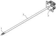
图1为本发明提供的一种低摩擦损耗的手术器械的整体结构示意图;1 is a schematic diagram of the overall structure of a surgical instrument with low friction loss provided by the present invention;
图2为本发明提供的一种低摩擦损耗的手术器械中的器械底部的结构示意图;2 is a schematic structural diagram of the bottom of the instrument in a low friction loss surgical instrument provided by the present invention;
图3为本发明提供的一种低摩擦损耗的手术器械中的短管与长管的连接关系立体分解示意图;3 is a perspective exploded schematic diagram of the connection relationship between the short tube and the long tube in a low friction loss surgical instrument provided by the present invention;
图4为本发明提供的一种低摩擦损耗的手术器械中的器械前部的结构示意图;4 is a schematic structural diagram of the front part of the instrument in a low friction loss surgical instrument provided by the present invention;
图5为普通的手术器械在大自转180o时,器械长管内丝的理想缠绕情况示意图;Figure 5 is a schematic diagram of the ideal winding situation of the inner wire of the long tube of the instrument when the common surgical instrument rotates at a large rotation of 180o;
图6为本发明提供的一种低摩擦损耗的手术器械的器械前部与器械中部的连接结构分解示意图;6 is an exploded schematic diagram of the connection structure between the front part of the instrument and the middle part of the instrument of a low friction loss surgical instrument provided by the present invention;
图7为本发明提供的一种低摩擦损耗的手术器械,在控制器械中部和器械前部进行自转时,第一辅助控制丝与相关部件的连接状态示意图。Fig. 7 is a schematic diagram of the connection state between the first auxiliary control wire and the relevant components when the middle part of the control device and the front part of the device are rotated according to a low friction loss surgical instrument provided by the present invention.
具体实施方式Detailed ways
为了使本技术领域的人员更好地理解本发明方案,下面结合附图和实施方式对本发明作进一步的详细说明。In order to make those skilled in the art better understand the solution of the present invention, the present invention is further described in detail below with reference to the accompanying drawings and embodiments.
参见图1至图7,本发明提供了一种低摩擦损耗的手术器械,是一种微创手术系统末端执行器,包括器械前部1、器械中部2和器械底部3,其中:1 to 7, the present invention provides a surgical instrument with low friction loss, which is an end effector of a minimally invasive surgical system, including an instrument front 1, an instrument middle 2 and an
器械底部3,通过贯穿通过器械中部2的多根控制丝,与器械前部1相连接;The
器械底部3,用于通过主控制丝100,以及第一辅助控制丝()、第二辅助控制丝200b和第三辅助控制丝200c(即不同的控制丝),来对应控制器械前部1和器械中部2按照预设的方式进行运动。The
在本发明中,具体实现上,器械前部1包括中空的、两端开口的前端支架111;In the present invention, in terms of specific implementation, the front part 1 of the instrument comprises a hollow
前端支架111的一端与器械中部2相连接(具体是与长管204相卡接);One end of the
前端支架111的另一端具有突出的两个边缘部,分别通过一个连接销,与一个偏转支架105相铰接(偏转支架105可以相对前端支架111转动);The other end of the
偏转支架105的一端端面(如图4所示的右端面)与前端支架111的另一端之间,具有中空的豁口;There is a hollow gap between one end face of the deflection bracket 105 (the right end face as shown in FIG. 4 ) and the other end of the
偏转支架105的上下两端内侧,分别安装有可转动的第一滑轮108和第二滑轮109;The inner sides of the upper and lower ends of the
第一滑轮108上焊接有第一锥齿轮106,第二滑轮109上焊接有第二锥齿轮107;A
因此,第一锥齿轮106和第二锥齿轮107,可以相对偏转支架105进行旋转运动。Therefore, the
偏转支架105朝向前端支架111的端面,设置有第三锥齿轮1050;The end face of the
第三锥齿轮1050具有横向分布的中心通孔;The
偏转支架105的另一端,与锥结构钳架104的一端为枢接(即可相对转动地连接);例如,锥结构钳架104的一端固定连接(例如焊接)一个轴承的内圈一侧,该轴承的内圈另一侧固定连接(例如焊接)第三锥齿轮1050。The other end of the
锥结构钳架104的一端具有与第三锥齿轮1050的中心通孔,相对应连通的主控制丝第三通孔1003;One end of the conical
锥结构钳架104的另一端,通过连接销,与一个拉座102的一端(即后端)相铰接;The other end of the conical
拉座102的一端(即后端)固定设置有连接弹簧103,该连接弹簧103嵌入到主控制丝第三通孔1003中,由主控制丝第三通孔1003进行限位,连接弹簧103用于连接主控制丝100,主控制丝第三通孔1003用于通过主控制丝100;One end (ie, the rear end) of the
拉座102的另一端(即前端),通过连接销,与开合钳101相连接。The other end (ie, the front end) of the
具体实现上,前端支架111的另一端中心位置与第二连接卡片110相卡接;In terms of specific implementation, the center position of the other end of the
第二连接卡片110上具有四个辅助控制丝第二通孔2002,以及一个主控制丝第二通孔1002;The
四个辅助控制丝第二通孔2002,用于分别通过两根第二辅助控制丝200b和两根第三辅助控制丝200c,需要说明的是,第二辅助控制丝200b和第三辅助控制丝200c来回通过两次第二连接卡片110;The second through
主控制丝第二通孔1002,用于通过主控制丝100。The second through
需要说明的是,对于本发明,开合钳101,用于对手术对象起到夹持的作用;拉座102,作为控制丝的终点连接处,用于传递运动;It should be noted that, for the present invention, the opening and closing
锥结构钳架104,用于对开合钳101以及连接弹簧103进行限位,传递小自转运动。The conical
偏转支架105、前端支架111用于对其上的部件起到支撑作用;The
第一锥齿轮106和第一滑轮108,用于传递小自转运动;The
第二锥齿轮7,用于第一锥齿轮平衡106的运动;The second bevel gear 7 is used to balance the movement of the
第二滑轮109,用于传递偏转运动;The
第二连接卡片110,用于限位相关的控制丝,以及连接空心内芯203。The
在本发明中,具体实现上,器械中部2包括中空的长管204;In the present invention, in terms of specific implementation, the
长管204内部具有一根空心内芯203;The
空心内芯203内部用于通过主控制丝100;The inside of the
空心内芯203的外表面和长管204的内表面之间的空隙,用于通过第二辅助控制丝200b和第三辅助控制丝200c;a space between the outer surface of the hollow
空心内芯203的一端,与器械前部1中的第二连接卡片110相卡接(具体可以是与第二连接卡片110自身具有的卡槽相卡接);One end of the hollow
空心内芯203的另一端与第一连接卡片202上的卡槽相卡接;The other end of the hollow
第一连接卡片202卡接在一根短管201的一端(例如短管201内腔的卡槽上);The
短管201的另一端,与器械底部3中的底座301相枢接,具体可以为:短管201的另一端通过一个轴承与器械底部3中的底座301相枢接,例如,短管201的另一端固定连接(例如焊接)一个轴承的内圈一侧,该轴承的内圈另一侧固定连接(例如焊接)器械底部。The other end of the
具体实现上,长管204通过短管201一端内部的卡槽限定位置,且和第一连接卡片202的表面相接触。In terms of specific implementation, the position of the
具体实现上,第一连接卡片202的中心位置,具有主控制丝第一通孔1001,用于通过主控制丝100;In terms of specific implementation, the central position of the
第一连接卡片202的四周边缘,具有两个辅助控制丝第一通孔2001,用于通过用于控制小自传,以及偏转运动的辅助控制丝(即能够用于控制器械前部进行小自转运动的第二辅助控制丝200b,以及能够用于控制器械前部进行偏转运动的第三辅助控制丝200c)。The peripheral edge of the
需要说明的是,对于本发明,短管201,用于作为外腔,保护内部的丝、限定第一连接卡片202的位置、参与控制整个器械的大自转,以及带动器械中部、前部的转动;It should be noted that, for the present invention, the
第一连接卡片202主要是用来限定空心内芯203、几根控制丝在长管204中的相对位置;The
空心内芯203,用于防止控制小自转、偏转、开合的控制丝,在器械自转时缠绕在一起。The hollow
长管204用于作为外壳,保护内部的丝,以及连接整个器械的底部和前部。The
在本发明中,具体实现上,器械底部3包括正方形的底座301;In the present invention, in terms of specific implementation, the
底座301的后侧面四角分别铰接设置有第一控制轮3091、第二控制轮3092、第三控制轮3093和第四控制轮3094;A
第一控制轮3091、第二控制轮3092、第三控制轮3093和第四控制轮3094上,分别通过螺纹抱紧有第一抱紧轮302、第二抱紧轮303、第三抱紧轮304和第四抱紧轮305;On the
第一控制轮3091、第二控制轮3092、第三控制轮3093和第四控制轮3094,分别与一个外部电机的驱动输出轴相连接(例如通过联轴器或者万向节)。The
具体实现上,底座301的中心位置,具有用于通过各种控制丝的中心通孔,从而可以让控制丝进入到短管以及长管中,最后到器械前部。In terms of specific implementation, the center position of the
需要说明的是,对于本发明,第一控制轮3091、第二控制轮3092、第三控制轮3093和第四控制轮3094等四个控制轮,主要是运动的输入端,外部电机的驱动,可以通过四个控制轮传入本发明的手术器械,从而驱动对应的抱紧轮转动。It should be noted that, for the present invention, the four control wheels, such as the
对于本发明,第一抱紧轮302、第二抱紧轮303、第三抱紧轮304和第四抱紧轮305,分别用于抱紧对应的控制轮,驱动所连接的控制丝(例如主控制丝和辅助控制丝)的运动。In the present invention, the first
具体实现上,第一抱紧轮302、第二抱紧轮303和第三抱紧轮304的上半部分,分别固定连接第一辅助控制丝200a、第二辅助控制丝200b和第三辅助控制丝200c(即一根丝线)的一端;In terms of specific implementation, the upper half of the
第一辅助控制丝200a的另一端,在与器械中部2中的短管201缠绕后(具体为缠绕预设的圈数,例如2圈,3圈),返回固定连接第一抱紧轮302的下半部分;The other end of the first
第二辅助控制丝200b的另一端,在与第一滑轮108缠绕后,返回固定连接第二抱紧轮303的下半部分;The other end of the second
第三辅助控制丝200c的另一端,在与第二滑轮109缠绕后,返回固定连接第三抱紧轮304的下半部分。The other end of the third
具体实现上,第四抱紧轮305的上半部分,固定连接主控制丝100的一端;In terms of specific implementation, the upper half of the
主控制丝100的另一端,与器械前部1中的拉座102固定连接。The other end of the
需要说明的是,第一辅助控制丝200a能够用于控制器械前部1以及器械中部2进行自转运动;It should be noted that the first
第二辅助控制丝200b能够用于控制器械前部进行小自转运动;The second
第三辅助控制丝200c能够用于控制器械前部进行偏转运动;The third
主控制丝100能够用于控制器械前部中的拉座102所连接的开合钳101进行开合运动,即它控制开合钳101开合的丝。其他控制丝,分别对应控制不同的运动方式,其中,图2标注了用于控制器械前部进行小自转运动的第二辅助控制丝200b的缠绕位置;The
具体实现上,为了给第一辅助控制丝200a、第二辅助控制丝200b和第三辅助控制丝200c等三条辅助控制丝,以及主控制丝100的转动提供路径、支撑,对于本发明,底座301的中心区域位置,还设置有中空的滑轮组安装壳体300,该壳体呈圆柱形;In terms of specific implementation, in order to provide a path and support for the rotation of the three auxiliary control wires including the first
滑轮组安装壳体300上安装有第一滑轮组件306、第二滑轮组件307和第三滑轮组件308;A
第一滑轮组件306、第二滑轮组件307和第三滑轮组件308,均包括两个并列放置的滑轮;The
滑轮组安装壳体300的侧壁上,沿着周向开有一个豁口3001,用于通过第一辅助控制丝200a;On the side wall of the pulley
短管201伸入到滑轮组安装壳体300中,并且短管201伸入到滑轮组安装壳体300中的外壳上具有预留的第一辅助控制丝缠绕槽。The
具体实现上,第一滑轮组件306、第二滑轮组件307和第三滑轮组件308,分别与滑轮组安装壳体300之间为螺纹固定连接。In terms of specific implementation, the
需要说明的是,第一辅助控制丝200a、第二辅助控制丝200b和第三辅助控制丝200c等三条辅助控制丝,在与所需要连接的目的零件相连接的中段,可以分别缠绕在第一滑轮组件306、第二滑轮组件307和第三滑轮组件308具有的一个滑轮表面,用于有效减少控制丝在被拉动时的摩擦力,同时,方便力的传递。It should be noted that, the three auxiliary control wires, such as the first
需要说明的是,对于本发明,主控制丝100所控制进行的开合钳的开合运动是单向的;第一辅助控制丝200a、第二辅助控制丝200b和第三辅助控制丝200c等三条辅助控制丝,其缠绕的路径,形成了一个回路(即辅助控制丝的一端固定在一个抱紧轮中,另一端从抱紧轮出发,经过其他零件后回到该抱紧轮上)。It should be noted that, for the present invention, the opening and closing motion of the opening and closing pliers controlled by the
在本发明中,具体实现上,本发明的手术器械的自由度保持与其他器械的运动控制基本相同,也就是包含自转、偏转、开合、小自转这四个运动控制,长距离的传动方式也是以丝传动为主体。In the present invention, in terms of specific implementation, the degree of freedom of the surgical instrument of the present invention remains basically the same as the motion control of other instruments, that is, the four motion controls of rotation, deflection, opening and closing, and small rotation are included, and the long-distance transmission mode It is also dominated by wire transmission.
在本发明中,具体实现上,本发明对器械的细长直管(即长管)内的结构进行了创新,以此来减少细长直管管内丝的摩擦损耗。In the present invention, in terms of specific implementation, the present invention innovates the structure in the slender straight tube (ie, the long tube) of the instrument, so as to reduce the friction loss of the inner wire of the slender straight tube.
在本发明中,具体实现上,本发明对部分传动形式进行了调整,将小自转的丝传动控制,改为了丝传动结合锥齿轮传动的传动形式,以此来替代用丝传动进行正交传动。In the present invention, in terms of specific implementation, the present invention adjusts part of the transmission form, and changes the wire transmission control of small rotation to the transmission form of wire transmission combined with bevel gear transmission, so as to replace the use of wire transmission for orthogonal transmission .
对于本发明,该手术器械能够实现四个运动,分别是:自转、小自转、开合、偏转。For the present invention, the surgical instrument can realize four movements, namely: rotation, small rotation, opening and closing, and deflection.
一、自转。1. Rotation.
对于本发明,其控制自转丝缠绕的途径为:一根第一辅助控制丝200a的一端固定在第一抱紧轮302的上半部分,缠绕2-3圈之后,伸出(可以从滑轮组安装壳体300侧壁上的豁口3001)缠绕在短管201外壳(具有预留的第一辅助控制丝缠绕槽)上2-3圈,之后回到第一抱紧轮302下下半部分,并固定丝的另一端。For the present invention, the way to control the winding of the spinning wire is: one end of a first
具体实现上,本发明控制自转的运动传递途径为:相对应的第一控制轮旋转时,会带动第一抱紧轮302旋转,第一抱紧轮302则会带动短管201转动,短管201则通过内部的卡槽带动整个器械前部1和器械中部2转动,实现自转(即大自传)。In terms of specific implementation, the motion transmission path for controlling the rotation of the present invention is as follows: when the corresponding first control wheel rotates, it will drive the
二、小自转。Second, the small rotation.
对于本发明,控制小自转丝的缠绕途径为:一根第二辅助控制丝200b的一端固定在第二抱紧轮303上半部分,缠绕2-3圈后,伸出缠绕在第一滑轮组306其中一个滑轮表面,向器械前端延伸,从第一连接卡片202靠近边缘的槽穿过,沿着空心内芯203外表面和长管204的内表面之间的空隙向器械前部1(即端部)延伸,而后经过第二连接卡片110的边缘孔(即辅助控制丝第二通孔2002),缠绕在第一滑轮108上180°,而后,又回到过第二连接卡片110的另一个边缘孔(即辅助控制丝第二通孔2002),穿过空心内芯203的外表面和长管204的内表面之间的空隙,经过第一连接卡片202靠近边缘的槽,向器械底部3方向延伸,经过短管201,缠绕在第一滑轮组306的另一个滑轮表面,回到第二抱紧轮303的下半部分。For the present invention, the winding method of the control small rotation wire is as follows: one end of a second
具体实现上,本发明进行小自转运动传递的途径为:相对应的第二控制轮转动,带动第二抱紧轮303转动,带动丝运动,丝经过第一滑轮组306、短管201、第一连接卡片202、长管204、第二连接卡片110,带动第一滑轮108转动,又由于第一滑轮108和第一锥齿轮106焊接在一起,带动第一锥齿轮106转动,第一锥齿轮106通过齿轮传动带动锥结构钳架104转动,从而开合钳101、拉座102、连接弹簧103随之转动,锥结构钳架104转动又带动第二锥齿轮107空转。In terms of specific implementation, the method of the present invention to transmit the small rotation motion is as follows: the corresponding second control wheel rotates, which drives the
三、开合。Three, opening and closing.
对于本发明,控制开合运动丝的缠绕途径为:一根主控制丝100的一端固定在第四抱紧轮305上半部分,缠绕2-3圈后,伸出缠绕在第三滑轮组308其中一个滑轮表面,向器械前端延伸,从第一连接卡片202靠近中心的孔穿过,沿着空心内芯203的中心孔向器械前端延伸,而后经过第二连接卡片110的中心孔,继续经过锥结构钳架104的中心孔,穿过连接弹簧103,固定在拉座102上。According to the present invention, the winding method of the control opening and closing motion wire is as follows: one end of a
具体实现上,本发明进行开合运动的传递途径为:相对应的控制轮转动,带动第四抱紧轮305转动,从而拉动丝运动,经过经过第三滑轮组308、短管201、第一连接卡片202、空心内芯203、第二连接卡片110,锥结构钳架104,拉动拉座102向下运动,控制开合钳闭合;松开力之后,由于连接弹簧103的弹力,开合钳张开。In terms of specific implementation, the transmission path for the opening and closing movement of the present invention is as follows: the corresponding control wheel rotates, which drives the
四、偏转运动。4. Deflection movement.
对于本发明,其控制偏转丝的缠绕途径为:丝的一端固定在第三抱紧轮304上半部分,缠绕2-3圈后,伸出缠绕在第二滑轮组307其中一个滑轮表面,向器械前端延伸,从第一连接卡片202靠近边缘的槽穿过,沿着空心内芯203外表面和长管204的内表面之间的空隙向器械前部1延伸,而后经过第二连接卡片110的边缘孔,缠绕在第二滑轮109上1800,而后,又回到第二连接卡片110的另一个边缘孔,穿过空心内芯203外表面和长管204的内表面之间的空隙,经过第一连接卡片202靠近边缘的槽,向器械底部3延伸,经过短管201,缠绕在第二滑轮组307的另一个滑轮表面,回到第三抱紧轮304的下半部分。For the present invention, the winding method of the control deflection wire is as follows: one end of the wire is fixed on the upper half of the third tightening
具体实现上,本发明控制偏转运动的传递路径为:相对应的控制轮转动,带动第三抱紧轮304转动,带动丝运动,丝经过第一滑轮组306、短管201、第一连接卡片202、长管204、第二连接卡片110,带动第二滑轮109转动,又由于第二滑轮109和偏转支架105焊接,带动偏转支架105转动,从而开合钳101,拉座102,连接弹簧103,锥结构钳架104随之偏转。In terms of specific implementation, the transmission path of the control deflection motion of the present invention is as follows: the corresponding control wheel rotates, which drives the
需要说明的是,对于器械的丝传动而言,磨损主要来自两方面,一是丝与丝之间的摩擦导致的磨损,二是丝与接触的机械结构摩擦造成的磨损,为解决两个问题,本发明的器械有下面两个具体创新方式。It should be noted that for the wire transmission of the instrument, the wear mainly comes from two aspects, one is the wear caused by the friction between the wire and the wire, and the other is the wear caused by the friction between the wire and the mechanical structure in contact. In order to solve the two problems , the apparatus of the present invention has the following two specific innovative ways.
一是采用了丝传动和传统机械传动(齿轮传动)结合的方式。在小自转的运动上,因为该运动具有两个特点:长距离、正交传动。本器械采用锥齿轮传动(104、106)以及丝传动(第二抱紧轮303、第一滑轮组件306、短管201、第一连接卡片202、长管204、第二连接卡片110、第一滑轮108)相结合的方式,实现这个运动,如图4。这能够很好的解决单纯使用丝传动来实现该运动的问题——用丝传动实现正交存在传动精度不好、稳定性不高、对丝的磨损大等问题。First, the combination of wire transmission and traditional mechanical transmission (gear transmission) is adopted. In the movement of small rotation, because the movement has two characteristics: long-distance, orthogonal transmission. The device adopts bevel gear drive (104, 106) and wire drive (second
二是,鉴于普通手术器械在使用过程中,会因为器械的自转而让控制运动的丝在长直管中在一个位置缠绕(图5),丝会产生很大的损耗。本发明的器械通过改进细长直管内部结构,增加了第一连接卡片202、空心内芯203、第二连接卡片110,解决这一问题。器械首先通过第一连接卡片202、第二连接卡片110控制丝在进出口的位置确定,保证丝在进出口位置能够以最合理的角度与前端的滑轮、端部的导向轮相接,避免丝和滑轮、导向轮的边角相接造成摩擦;另外,在细长直管中加入了一个低摩擦系数的空心内芯203,让控制器械开合运动的丝穿过过空心内芯203,其他的丝从内芯外部通过。这样不仅减少了相互摩擦丝的数量,而且当器械自转时,外部四根丝会因为进出口位置的确定,以及空心管的存在,丝会缠绕在低摩擦系数的空心内芯203上,而不会相互接触造成损耗。Second, in view of the fact that during the use of ordinary surgical instruments, the wire that controls the movement will be wound at one position in the long straight tube due to the rotation of the instrument (Fig. 5), and the wire will produce a lot of loss. The apparatus of the present invention solves this problem by improving the internal structure of the slender straight tube and adding the first connecting
与现有技术相比较,本发明提供的低摩擦损耗的手术器械,通过对手术器械中的不合理结构优化,以及通过部分传动形式的改变,增加了运动实现的可靠性,调整了器械中不合理的一些结构,避免了传动过程中丝的磨损,增加了部分运动的精度。同时,本发明增加了一些能够减少器械磨损的部件。Compared with the prior art, the surgical instrument with low friction loss provided by the present invention increases the reliability of motion realization by optimizing the unreasonable structure in the surgical instrument and changing part of the transmission form, and adjusts the unreasonable structure in the instrument. Reasonable structures avoid wire wear during transmission and increase the precision of some movements. At the same time, the present invention adds some components that can reduce the wear of the instrument.
综上所述,与现有技术相比较,本发明提供的一种低摩擦损耗的手术器械,其能够解决手术器械在使用过程中丝摩擦损耗很严重的问题,通过对丝传动结构的一些改进,以及引入锥齿轮传动替代器械中的部分丝传动,减小了丝的摩擦损耗,同时还提高了器械小自转的传动精度,具有重大的实践意义。To sum up, compared with the prior art, the present invention provides a surgical instrument with low friction loss, which can solve the problem that the wire friction loss is very serious during the use of the surgical instrument. Through some improvements to the wire transmission structure , and the introduction of bevel gear transmission to replace part of the wire transmission in the instrument, which reduces the friction loss of the wire, and at the same time improves the transmission accuracy of the small rotation of the instrument, which has great practical significance.
以上所述仅是本发明的优选实施方式,应当指出,对于本技术领域的普通技术人员来说,在不脱离本发明原理的前提下,还可以做出若干改进和润饰,这些改进和润饰也应视为本发明的保护范围。The above are only the preferred embodiments of the present invention. It should be pointed out that for those skilled in the art, without departing from the principles of the present invention, several improvements and modifications can be made. It should be regarded as the protection scope of the present invention.
Claims (9)
Priority Applications (1)
| Application Number | Priority Date | Filing Date | Title |
|---|---|---|---|
| CN201910519398.2ACN110279442B (en) | 2019-06-17 | 2019-06-17 | Surgical instrument with low friction loss |
Applications Claiming Priority (1)
| Application Number | Priority Date | Filing Date | Title |
|---|---|---|---|
| CN201910519398.2ACN110279442B (en) | 2019-06-17 | 2019-06-17 | Surgical instrument with low friction loss |
Publications (2)
| Publication Number | Publication Date |
|---|---|
| CN110279442A CN110279442A (en) | 2019-09-27 |
| CN110279442Btrue CN110279442B (en) | 2022-06-07 |
Family
ID=68004699
Family Applications (1)
| Application Number | Title | Priority Date | Filing Date |
|---|---|---|---|
| CN201910519398.2AActiveCN110279442B (en) | 2019-06-17 | 2019-06-17 | Surgical instrument with low friction loss |
Country Status (1)
| Country | Link |
|---|---|
| CN (1) | CN110279442B (en) |
Citations (4)
| Publication number | Priority date | Publication date | Assignee | Title |
|---|---|---|---|---|
| CN103251458A (en)* | 2013-05-09 | 2013-08-21 | 天津工业大学 | Wire transmission four-freedom-degree surgical instrument for minimally invasive surgery robot |
| CN104116547A (en)* | 2014-07-25 | 2014-10-29 | 上海交通大学 | Low-friction low-inertia surgical instrument for minimally invasive surgical robot |
| CN106037932A (en)* | 2016-06-20 | 2016-10-26 | 微创(上海)医疗机器人有限公司 | Surgical instrument and surgical robot adopting same |
| CN208910328U (en)* | 2018-03-13 | 2019-05-31 | 锐志微创医疗科技(常州)有限公司 | Minimally Invasive Surgery instrument |
Family Cites Families (1)
| Publication number | Priority date | Publication date | Assignee | Title |
|---|---|---|---|---|
| US5792135A (en)* | 1996-05-20 | 1998-08-11 | Intuitive Surgical, Inc. | Articulated surgical instrument for performing minimally invasive surgery with enhanced dexterity and sensitivity |
- 2019
- 2019-06-17CNCN201910519398.2Apatent/CN110279442B/enactiveActive
Patent Citations (4)
| Publication number | Priority date | Publication date | Assignee | Title |
|---|---|---|---|---|
| CN103251458A (en)* | 2013-05-09 | 2013-08-21 | 天津工业大学 | Wire transmission four-freedom-degree surgical instrument for minimally invasive surgery robot |
| CN104116547A (en)* | 2014-07-25 | 2014-10-29 | 上海交通大学 | Low-friction low-inertia surgical instrument for minimally invasive surgical robot |
| CN106037932A (en)* | 2016-06-20 | 2016-10-26 | 微创(上海)医疗机器人有限公司 | Surgical instrument and surgical robot adopting same |
| CN208910328U (en)* | 2018-03-13 | 2019-05-31 | 锐志微创医疗科技(常州)有限公司 | Minimally Invasive Surgery instrument |
Also Published As
| Publication number | Publication date |
|---|---|
| CN110279442A (en) | 2019-09-27 |
Similar Documents
| Publication | Publication Date | Title |
|---|---|---|
| CN111134850B (en) | Drive box, operation arm and surgical robot | |
| CN102143719B (en) | Back-end mechanism of four-cable wrist | |
| CN106691593B (en) | Micro-instrument clamping mechanism for minimally invasive surgery | |
| CN108670320A (en) | Snakelike surgical instrument | |
| AU2002335791A1 (en) | Cycling suturing and knot-tying device | |
| CN106214258A (en) | A kind of dexterous wrist mechanism for single hole minimally invasive robot | |
| CN119073875B (en) | Driving structure of haulage rope, operating handle and endoscope | |
| JP2006159305A (en) | Filament body guide device for robot and robot provided with filament body guide device | |
| CN115633997A (en) | A minimally invasive surgical instrument capable of automatic opening, closing and rotation | |
| CN110279442B (en) | Surgical instrument with low friction loss | |
| WO2024022048A1 (en) | End effector mechanism of surgical instrument, and surgical instrument | |
| WO2024174585A1 (en) | Surgical instrument and surgical robot | |
| CN111166468B (en) | A surgical electrocoagulation hook | |
| CN211750045U (en) | Drive box, operation arm and surgical robot | |
| CN102465957A (en) | Hollowed-out transmission part for multi degree of freedom transmission mechanism | |
| CN115137284A (en) | A 3D endoscope | |
| CN209734146U (en) | Minimally invasive robot clamp holder | |
| WO2025007701A1 (en) | Surgical execution mechanism, surgical instrument and surgical robot | |
| CN221671971U (en) | Surgical robot end effector connector | |
| WO2024104089A1 (en) | Hemostatic clamp | |
| CN110464388B (en) | Handheld minimally invasive medical surgical instrument with multiple-degree-of-freedom motion control | |
| CN115300049B (en) | Multi-degree-of-freedom surgical clamp | |
| CN112043391B (en) | Surgical instruments, operating equipment and surgical robots | |
| CN112716564B (en) | Large-swing-angle single-joint surgical instrument | |
| CN110251165B (en) | Handheld endoscopic instruments |
Legal Events
| Date | Code | Title | Description |
|---|---|---|---|
| PB01 | Publication | ||
| PB01 | Publication | ||
| SE01 | Entry into force of request for substantive examination | ||
| SE01 | Entry into force of request for substantive examination | ||
| GR01 | Patent grant | ||
| GR01 | Patent grant |