CN110266016B - Control strategy applied to power decoupling PFC topology and used for improving power factor - Google Patents
Control strategy applied to power decoupling PFC topology and used for improving power factorDownload PDFInfo
- Publication number
- CN110266016B CN110266016BCN201910422914.XACN201910422914ACN110266016BCN 110266016 BCN110266016 BCN 110266016BCN 201910422914 ACN201910422914 ACN 201910422914ACN 110266016 BCN110266016 BCN 110266016B
- Authority
- CN
- China
- Prior art keywords
- decoupling
- voltage
- power
- control
- phase
- Prior art date
- Legal status (The legal status is an assumption and is not a legal conclusion. Google has not performed a legal analysis and makes no representation as to the accuracy of the status listed.)
- Active
Links
- 238000011217control strategyMethods0.000titleclaimsabstractdescription12
- 239000003990capacitorSubstances0.000claimsabstractdescription33
- 238000012937correctionMethods0.000claimsabstractdescription19
- 230000009471actionEffects0.000claimsdescription6
- 238000005070samplingMethods0.000claimsdescription6
- 238000012546transferMethods0.000claimsdescription6
- 230000005540biological transmissionEffects0.000claimsdescription4
- 230000000694effectsEffects0.000claimsdescription4
- 230000010354integrationEffects0.000claimsdescription3
- 230000003068static effectEffects0.000claimsdescription3
- 230000003139buffering effectEffects0.000claimsdescription2
- 230000007274generation of a signal involved in cell-cell signalingEffects0.000claims1
- 238000000034methodMethods0.000abstractdescription10
- 230000002457bidirectional effectEffects0.000abstractdescription4
- 230000008859changeEffects0.000abstractdescription2
- 238000004891communicationMethods0.000description9
- 238000005516engineering processMethods0.000description6
- 238000004146energy storageMethods0.000description4
- 238000010586diagramMethods0.000description3
- 230000009467reductionEffects0.000description3
- 238000011161developmentMethods0.000description2
- 230000009286beneficial effectEffects0.000description1
- 230000015556catabolic processEffects0.000description1
- 230000007812deficiencyEffects0.000description1
- 238000006731degradation reactionMethods0.000description1
- 230000006872improvementEffects0.000description1
- 238000002955isolationMethods0.000description1
- 239000013307optical fiberSubstances0.000description1
- 238000005457optimizationMethods0.000description1
- 230000008569processEffects0.000description1
- 238000003908quality control methodMethods0.000description1
- 238000011160researchMethods0.000description1
Images
Classifications
- H—ELECTRICITY
- H02—GENERATION; CONVERSION OR DISTRIBUTION OF ELECTRIC POWER
- H02J—CIRCUIT ARRANGEMENTS OR SYSTEMS FOR SUPPLYING OR DISTRIBUTING ELECTRIC POWER; SYSTEMS FOR STORING ELECTRIC ENERGY
- H02J3/00—Circuit arrangements for AC mains or AC distribution networks
- H02J3/01—Arrangements for reducing harmonics or ripples
- H—ELECTRICITY
- H02—GENERATION; CONVERSION OR DISTRIBUTION OF ELECTRIC POWER
- H02J—CIRCUIT ARRANGEMENTS OR SYSTEMS FOR SUPPLYING OR DISTRIBUTING ELECTRIC POWER; SYSTEMS FOR STORING ELECTRIC ENERGY
- H02J3/00—Circuit arrangements for AC mains or AC distribution networks
- H02J3/18—Arrangements for adjusting, eliminating or compensating reactive power in networks
- H02J3/1807—Arrangements for adjusting, eliminating or compensating reactive power in networks using series compensators
- H02J3/1814—Arrangements for adjusting, eliminating or compensating reactive power in networks using series compensators wherein al least one reactive element is actively controlled by a bridge converter, e.g. unified power flow controllers [UPFC]
- Y—GENERAL TAGGING OF NEW TECHNOLOGICAL DEVELOPMENTS; GENERAL TAGGING OF CROSS-SECTIONAL TECHNOLOGIES SPANNING OVER SEVERAL SECTIONS OF THE IPC; TECHNICAL SUBJECTS COVERED BY FORMER USPC CROSS-REFERENCE ART COLLECTIONS [XRACs] AND DIGESTS
- Y02—TECHNOLOGIES OR APPLICATIONS FOR MITIGATION OR ADAPTATION AGAINST CLIMATE CHANGE
- Y02E—REDUCTION OF GREENHOUSE GAS [GHG] EMISSIONS, RELATED TO ENERGY GENERATION, TRANSMISSION OR DISTRIBUTION
- Y02E40/00—Technologies for an efficient electrical power generation, transmission or distribution
- Y02E40/30—Reactive power compensation
- Y—GENERAL TAGGING OF NEW TECHNOLOGICAL DEVELOPMENTS; GENERAL TAGGING OF CROSS-SECTIONAL TECHNOLOGIES SPANNING OVER SEVERAL SECTIONS OF THE IPC; TECHNICAL SUBJECTS COVERED BY FORMER USPC CROSS-REFERENCE ART COLLECTIONS [XRACs] AND DIGESTS
- Y02—TECHNOLOGIES OR APPLICATIONS FOR MITIGATION OR ADAPTATION AGAINST CLIMATE CHANGE
- Y02E—REDUCTION OF GREENHOUSE GAS [GHG] EMISSIONS, RELATED TO ENERGY GENERATION, TRANSMISSION OR DISTRIBUTION
- Y02E40/00—Technologies for an efficient electrical power generation, transmission or distribution
- Y02E40/40—Arrangements for reducing harmonics
Landscapes
- Engineering & Computer Science (AREA)
- Power Engineering (AREA)
- Rectifiers (AREA)
- Control Of Electrical Variables (AREA)
Abstract
Description
Translated fromChinese技术领域technical field
本发明属于电力工业领域,具体涉及一种应用于功率解耦PFC拓扑的提高功率因数的控制策略。本发明基于功率解耦PFC拓扑的运行模式控制,针对该电路中无源储能元件引起的无功功率导致功率因数降低提出了相应的优化策略,适用于功率解耦、能量流动、输入输出的电能质量控制等多个应用场合。The invention belongs to the field of electric power industry, and particularly relates to a control strategy for improving power factor applied to a power decoupling PFC topology. The invention is based on the operation mode control of the power decoupling PFC topology, and proposes a corresponding optimization strategy for the reduction of the power factor caused by the reactive power caused by the passive energy storage element in the circuit, and is suitable for power decoupling, energy flow, input and output. Power quality control and many other applications.
背景技术Background technique
随着电力电子技术在工业自动化、电力系统、交通运输和可再生能源系统等领域的发展,高效电力电子变换器技术已成为实现高功率因数和低输入谐波电流的关键技术,被称为发展电力电子技术的使能技术。然而,电力电子器件的广泛应用使谐波污染问题越来越严重。IEC 61000-3-2明确规定了输入电流谐波分量的限值,为了提高电网供电质量、抑制谐波污染,功率校正因数校正(PFC)技术应运而生。With the development of power electronic technology in the fields of industrial automation, power system, transportation and renewable energy system, high-efficiency power electronic converter technology has become the key technology to achieve high power factor and low input harmonic current, which is called development Enabling technologies for power electronics. However, the widespread application of power electronic devices makes the problem of harmonic pollution more and more serious. IEC 61000-3-2 clearly stipulates the limit value of the harmonic components of the input current. In order to improve the power supply quality of the power grid and suppress harmonic pollution, the Power Correction Factor Correction (PFC) technology emerges as the times require.
与传统的功率因数校正拓扑相比,具有有源功率解耦功能的新型功率解耦PFC电路已成为拥有高效、高功率密度、高可靠性的主流拓扑之一。传统PFC中交流侧功率含有较大的二倍工频分量,需要大的储能电容进行功率解耦。大容量电解电容的存在,不仅限制了系统成本的降低和功率密度的提高,同时电解电容作为影响寿命的主要元件,对AC/DC变换器的可靠性有着极为关键的影响。功率解耦技术近年来一直是多个领域的的热点研究问题。Compared with the traditional power factor correction topology, the new power decoupling PFC circuit with active power decoupling function has become one of the mainstream topologies with high efficiency, high power density and high reliability. The AC side power in the traditional PFC contains a large double power frequency component, which requires a large energy storage capacitor for power decoupling. The existence of large-capacity electrolytic capacitors not only limits the reduction of system cost and the improvement of power density, but electrolytic capacitors, as the main components affecting life, have a critical impact on the reliability of AC/DC converters. Power decoupling technology has been a hot research topic in many fields in recent years.
目前提出的众多功率解耦拓扑中,通常会关注该拓扑在解耦效果和控制性能方面的有效性,而不考虑非理想电路情况下导致的电能质量下降问题。然而,由于大多功率解耦电路拓扑中无源储能元件较多,产生的无功功率不能忽略,会导致功率因数降低,尤其是在输入电压低、功率等级高的场合,而较低的功率因数会对电网造成一定的冲击。与传统的功率因数校正电路相比,新型解耦电路面临着更大的谐波挑战,产生的无功功率会影响电网电流的正弦度,从而影响供电质量,导致电网侧功率因数低,影响设备的正常运行。Among the many power decoupling topologies proposed at present, the effectiveness of the topology in terms of decoupling effect and control performance is usually concerned, without considering the power quality degradation caused by non-ideal circuit conditions. However, due to the large number of passive energy storage components in most power decoupling circuit topologies, the generated reactive power cannot be ignored, which will lead to reduced power factor, especially in the case of low input voltage and high power level, and lower power The factor will have a certain impact on the power grid. Compared with the traditional power factor correction circuit, the new decoupling circuit faces greater harmonic challenges. The generated reactive power will affect the sine degree of the grid current, thereby affecting the power supply quality, resulting in a low power factor on the grid side and affecting the equipment. of normal operation.
发明内容SUMMARY OF THE INVENTION
本发明要解决的技术方案是,克服现有技术中的不足,提供一种应用于功率解耦PFC拓扑的提高功率因数的控制策略。The technical solution to be solved by the present invention is to overcome the deficiencies in the prior art and provide a control strategy for improving the power factor applied to the power decoupling PFC topology.
为解决技术问题,本发明的解决方案是:For solving the technical problem, the solution of the present invention is:
提供一种应用于功率解耦PFC拓扑的提高功率因数的控制策略,包括:A control strategy for improving power factor applied to a power decoupling PFC topology is provided, including:
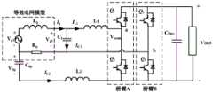
(1)由图腾柱式无桥PFC电路、控制电路和由解耦电感与电容组成的串联支路构成功率解耦PFC拓扑;其中,无桥PFC电路由升压电感L1、开关管Q1~4和母线电容Cbus组成,开关管Q1~4组成无桥Boost PFC拓扑,其中A桥臂的Q1~2充当PFC桥臂;B桥臂的Q3~4作为高频管与在网侧电压vg的阴极和整机地之间的LC串联解耦支路构成Buck电路,其开关动作将原本母线电容承受的电压纹波转移到解耦电容Cdp之上,电感L2作能量缓冲;电网的线路电感Lg、电容C1与电阻L1组成LCL滤波器;(1) The power decoupling PFC topology is composed of a totem-pole bridgeless PFC circuit, a control circuit and a series branch composed of a decoupling inductor and a capacitor; wherein, the bridgeless PFC circuit consists of a boost inductor L1 , a switch tube Q1 ~4 and bus capacitor Cbus , switch tubes Q1~4 form a bridgeless Boost PFC topology, in which Q1~2 of the A bridge arm act as the PFC bridge arm; Q3~4 of the B bridge arm are used as high frequency tubes and The LC series decoupling branch between the cathode of the grid side voltage vg and the ground of the whole machine constitutes a Buck circuit, and its switching action transfers the voltage ripple originally borne by the bus capacitor to the decoupling capacitor Cdp , and the inductance L2 acts as a buck circuit. Energy buffering; the line inductance Lg , the capacitor C1 and the resistance L1 of the power grid form an LCL filter;
LC串联解耦支路包含解耦电容和解耦电感,解耦电容用来平滑母线电压转移过来的纹波,解耦电感起到能量缓冲的作用。该支路与母线电压以及B桥臂组成Buck电路,目的是复用B桥臂的两个开关管,将母线电压上的二次纹波转移到解耦电容上。由于增加的解耦电容容值远远小于原有母线电容的容值,可以减小器件成本,提高整机功率密度。The LC series decoupling branch includes a decoupling capacitor and a decoupling inductance. The decoupling capacitor is used to smooth the ripple transferred from the bus voltage, and the decoupling inductance plays the role of energy buffer. This branch, the bus voltage and the B bridge arm form a Buck circuit, the purpose is to reuse the two switches of the B bridge arm and transfer the secondary ripple on the bus voltage to the decoupling capacitor. Since the capacitance value of the added decoupling capacitor is far smaller than that of the original bus capacitor, the cost of the device can be reduced and the power density of the whole machine can be improved.
(2)将检测到的电网电压和电网电流之间的相位偏移形成闭环控制来补偿参考电流相位,对拓扑中无功进行补偿控制,保证并网功率与所需要的参考电流相位偏移量相同;(2) The phase offset between the detected grid voltage and grid current is formed into closed-loop control to compensate the reference current phase, and the reactive power in the topology is compensated and controlled to ensure the grid-connected power and the required reference current phase offset. same;
(3)由统一的控制器根据电路状态和外部传输或内部预设的参考信号产生电路控制信号对电路中的开关管进行控制。(3) A unified controller generates a circuit control signal according to the circuit state and external transmission or an internal preset reference signal to control the switch tubes in the circuit.
本发明中,所述控制器中包括:In the present invention, the controller includes:
采样单元,对来自电网的输入电压Vg、内电感电流IL1以及母线电压Vdc进行采样;a sampling unit, sampling the input voltage Vg , the internal inductor current IL1 and the bus voltage Vdc from the power grid;
锁相单元,对输入电压Vg进行锁相,得到网侧电压的相位ωt;The phase-locking unit performs phase-locking on the input voltage Vg to obtain the phase ωt of the grid-side voltage;
乘法单元,将母线电压波动值与锁相单元所得正弦结果相乘;以及a multiplication unit that multiplies the bus voltage fluctuation value by the sine result obtained by the phase lock unit; and
解耦电压相位参考计算单元。Decoupled voltage phase reference calculation unit.
本发明中,具体包括以下步骤:In the present invention, the following steps are specifically included:
(1)在每一个控制周期内,控制器检测自身的输入电压Vg、内电感电流IL1以及母线电压Vdc,并根据电路状态和外部传输或内部预设的参考信号产生电路控制信号;控制环路由母线电压外环和电网电流内环组成,并向A桥臂的开关管提供PWM控制信号,保证该AC/DC电路稳定运行在正常PFC工作状态双环均采用经典PI控制;(1) In each control cycle, the controller detects its own input voltage Vg , internalinductor current IL1 and bus voltage Vdc , and generates a circuit control signal according to the circuit state and external transmission or internal preset reference signal; The control loop is composed of the bus voltage outer loop and the grid current inner loop, and provides PWM control signal to the switch tube of the A bridge arm to ensure that the AC/DC circuit runs stably in the normal PFC working state. Both loops adopt classic PI control;
(2)控制器检测母线电压Vdc上的纹波,经过计算得到相应的解耦电压参考值Vref_ripple用于控制B桥臂的开关管动作,将母线侧承受的纹波转移到解耦电容上;(2) The controller detects the ripple on the bus voltage Vdc , and obtains the corresponding decoupling voltage reference value Vref_ripple through calculation, which is used to control the switch action of the B bridge arm, and transfers the ripple on the bus side to the decoupling capacitor. superior;
(3)控制器检测自身的输入电压Vg、内电感电流IL1,除进行外电压环和内电流环计算外,还计算出每一个控制周期内自身实时输出无功功率Qout;再将其与0作差得到的误差值进入PI环节进行实时积分,得到内电感电流环相位参考修正角θ;通过对步骤(1)中经典双环控制的内电感电流IL1进行无功环补偿,实现对电网电压相位的无静差输出,保证得到的内电感电流环参考相位的准确跟踪从而提高功率因数;(3) The controller detects its own input voltage Vg and internal inductor current IL1 , and calculates its own real-time output reactive power Qout in each control cycle in addition to the calculation of the outer voltage loop and the inner current loop; The error value obtained by making a difference with 0 enters the PI link for real-time integration, and obtains the phase reference correction angle θ of the inner inductor current loop; by performing reactive power loop compensation on the innerinductor current IL1 of the classic dual-loop control in step (1), the realization of The output of grid voltage phase without static difference ensures the accurate tracking of the reference phase of the inner inductor current loop and improves the power factor;
(4)对电网电压进行PLL锁相,对锁相值ωt进行检测;将锁相值ωt减去步骤(3)得到的内电感电流环相位参考修正角θ的已修正内电感电流环相位参考值ωt-θ作为下一周期的内电感电流环相位参考;(4) PLL phase-locking the grid voltage, and detecting the phase-locking value ωt; subtracting the phase-locking value ωt from the corrected inner-inductor current-loop phase reference correction angle θ obtained in step (3) The value ωt-θ is used as the phase reference of the inner inductor current loop in the next cycle;
(5)对步骤(2)中解耦电压参考值Vref_ripple进行无功角补偿;(5) performing reactive angle compensation on the decoupling voltage reference value Vref_ripple in step (2);
控制器检测自身的输入电压Vg、内电感电流IL1,计算出每一个控制周期解耦电压相位参考值φ=arctan(ωL1IL1/Vg),与电网电压进行PLL锁相得到的二倍频基准2ωt相减得到已修正解耦电压参考值2ωt-φ作为下一周期的解耦电压参考值,保证精准解耦效果。The controller detects its own input voltage Vg and internal inductor current IL1 , calculates the decoupling voltage phase reference value φ=arctan(ωL1 IL1 /Vg ) in each control cycle, and performs PLL phase locking with the grid voltage to obtain The corrected decoupling voltage reference value 2ωt-φ is obtained by subtracting the double frequency reference 2ωt as the decoupling voltage reference value of the next cycle to ensure the accurate decoupling effect.
其中,内电感电流环相位参考修正角θ和解耦电压相位参考值φ分别是针对于内电感电流IL1和解耦电压参考值Vref_ripple的两个不同的无功补偿修正角。前者可以大幅度提高整机拓扑功率因数,后者可以进一步提高解耦能力,减小直流侧母线电容。The inner inductor current loop phase reference correction angle θ and the decoupling voltage phase reference value φ are respectively two different reactive power compensation correction angles for the inner inductor current IL1 and the decoupling voltage reference value Vref_ripple . The former can greatly improve the topological power factor of the whole machine, and the latter can further improve the decoupling capability and reduce the DC side bus capacitance.
本发明中,在每一个控制周期内,PFC控制与解耦控制同时进行,互相独立且互相牵制。既保证了原有PFC功能,又能在不添加有源器件和传感器的基础上减小母线电容容值,实现功率解耦。In the present invention, in each control cycle, the PFC control and the decoupling control are performed simultaneously, which are independent and mutually restrained. It not only ensures the original PFC function, but also reduces the capacitance value of the busbar without adding active devices and sensors, and realizes power decoupling.
在采用上述技术方案的基础上,本发明还可以采用或者组合采用以下进一步的技术方案:On the basis of adopting the above technical solutions, the present invention can also adopt or combine the following further technical solutions:
(1)所述的电路拓扑包含且不限于单级式和双级式双向AC/DC变化器。相较于单级式结构,双级式结构虽然器件数量较多,但弥补了单级式结构控制复杂、隔离困难、电池连接处电容大等的缺点,是现在主流的拓扑结构;The circuit topologies described in (1) include but are not limited to single-stage and two-stage bidirectional AC/DC converters. Compared with the single-stage structure, although the double-stage structure has a large number of devices, it makes up for the shortcomings of the single-stage structure, such as complex control, difficult isolation, and large capacitance at the battery connection. It is the current mainstream topology structure;
(2)所述的外部传输或内部预设的参考信号包含且不限于对网侧输入电压和电流、母线侧输出电压以及参考解耦电压波动状态的目标值进行修改;(2) The externally transmitted or internally preset reference signal includes but is not limited to modifying the target value of the grid-side input voltage and current, the bus-side output voltage and the reference decoupling voltage fluctuation state;
(3)可以引入SOGI控制模式,由于电网中含有谐波,可以通过SOGI精确锁定电网基波频率,从而引入正弦度更高的正弦参考;(3) The SOGI control mode can be introduced. Since the power grid contains harmonics, the fundamental frequency of the power grid can be precisely locked through SOGI, thereby introducing a sine reference with a higher sine degree;
(4)所述的外部传输的参考信号所涉及的通信方式,包含且不限于以下通信方式:(a)CAN通信、光纤通信、以太网通信等有线通信方式;(b)WiFi、ZigBee、蓝牙、红外等无线通信方式。(4) The communication methods involved in the externally transmitted reference signal include but are not limited to the following communication methods: (a) wired communication methods such as CAN communication, optical fiber communication, and Ethernet communication; (b) WiFi, ZigBee, Bluetooth, etc. , infrared and other wireless communication methods.
与现有技术相比,本发明的有益效果是:Compared with the prior art, the beneficial effects of the present invention are:
(1)本发明兼顾了功率解耦和功率因数校正功能,能解决功率解耦PFC拓扑中由于无源储能元件导致的功率因数下降的技术难题,抑制谐波,提高电能质量,同时实现良好的功率解耦性能。(1) The present invention takes into account the functions of power decoupling and power factor correction, can solve the technical problem of power factor reduction caused by passive energy storage elements in the power decoupling PFC topology, suppress harmonics, improve power quality, and achieve good power decoupling performance.
(2)无论是对于通信传输得到的外部参考信号,还是对于控制器内部预设的参考信号,本发明的控制方法均可以快速响应参考信号的变化,快速进行相位修正实现无功环补偿。(2) Whether it is an external reference signal obtained by communication transmission or a reference signal preset inside the controller, the control method of the present invention can quickly respond to the change of the reference signal, and quickly perform phase correction to realize reactive power loop compensation.
(3)本发明的控制方法同样适用于该拓扑的逆变模式,即不影响原本AC/DC电路双向工作的性能(正向用作功率因素校正,反向用作并网逆变),可以实现能量的双向流动。若工作在逆变模式下,内电感电流环相位参考修正角θ和解耦电压相位参考值φ为左移以使各功率部分平衡。(3) The control method of the present invention is also applicable to the inverter mode of this topology, that is, it does not affect the original bidirectional performance of the AC/DC circuit (the forward direction is used for power factor correction, and the reverse direction is used for grid-connected inverter), and it can be Realize the two-way flow of energy. If working in the inverter mode, the phase reference correction angle θ of the inner inductor current loop and the reference value φ of the decoupling voltage phase are shifted to the left to balance the power parts.
附图说明Description of drawings
图1是本发明所述功率解耦PFC拓扑示意图。FIG. 1 is a schematic diagram of a power decoupling PFC topology according to the present invention.
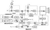
图2是本发明所述功率解耦PFC拓扑提高功率因数的控制策略总框图。FIG. 2 is a general block diagram of the control strategy for improving the power factor of the power decoupling PFC topology according to the present invention.
具体实施方式Detailed ways
本发明所述的功率解耦PFC拓扑提高功率因数的控制策略是基于图腾柱式无桥PFC电路外加LC串联支路及其控制器实现的。该AC/DC变换器和控制器的示意图如图1所示,其中无桥PFC电路由升压电感L1、开关管Q1~4和母线电容Cbus组成,外加LC串联解耦支路,而控制器根据电路状态和外部传输或内部预设的参考信号产生电路控制信号进行控制。The control strategy for improving the power factor of the power decoupling PFC topology of the present invention is realized based on the totem-pole bridgeless PFC circuit plus the LC series branch and its controller. The schematic diagram of the AC/DC converter and controller is shown in Figure 1, wherein the bridgeless PFC circuit is composed of boost inductor L1 , switch tubes Q1-4 and bus capacitor Cbus , plus LC series decoupling branch, The controller generates a circuit control signal for control according to the circuit state and an externally transmitted or internally preset reference signal.
在图1中:vg和ig分别是网侧交流电压和电流,vout和vdp分别是母线电容Cbus和解耦支路电容Cdp上的电压。开关管Q1~4组成无桥Boost PFC拓扑,其中A桥臂的Q1~2充当PFC桥臂,高频工作在开关频率实现PFC功能,L1是PFC电路中的升压电感;B桥臂的Q3~4原本为工频管,在此作高频管与在网侧电压vg的阴极和整机地之间的LC串联解耦支路构成Buck电路,其开关动作将原本母线电容承受的电压纹波转移到解耦电容Cdp之上,L2作能量缓冲。网侧Lg、C1与L1组成LCL滤波器,网侧电感利用电网的线路电感Lg代替。Rg为电网交流侧等效内阻。外部传输的参考信号由通信设备从外部传输到控制器。In Figure 1: vg andig are the AC voltage and current on the grid side, respectively, and vout and vdp are the voltages on the bus capacitor Cbus and the decoupling branch capacitor Cdp , respectively. The switches Q1-4 form a bridgeless Boost PFC topology, in which Q1-2 of the A bridge arm act as the PFC bridge arm, and the high frequency works at the switching frequency to realize the PFC function, and L1 is the boost inductor in the PFC circuit; B bridge The Q3~4 of the arm are originally power frequency tubes, here they are used as high frequency tubes and the LC series decoupling branch between the cathode of the grid side voltage vg and the ground of the whole machine constitutes a Buck circuit, and its switching action will convert the original bus bar. The voltage ripple experienced by the capacitor is transferred to the decoupling capacitor Cdp , and L2 acts as an energy buffer. The grid side Lg , C1 and L1 form an LCL filter, and the grid side inductance is replaced by the line inductance Lg of the grid. Rg is the equivalent internal resistance of the AC side of the grid. The externally transmitted reference signal is externally transmitted to the controller by the communication device.
解耦支路包含解耦电容和解耦电感,解耦电容用来平滑母线电压转移过来的纹波,解耦电感起到能量缓冲的作用。该支路与母线电压以及B桥臂组成Buck电路,目的是复用B桥臂的两个开关管,将母线电压上的二次纹波转移到解耦电容上。由于增加的解耦电容容值远远小于原有母线电容的容值,可以减小器件成本,提高整机功率密度。The decoupling branch includes a decoupling capacitor and a decoupling inductance. The decoupling capacitor is used to smooth the ripple transferred from the bus voltage, and the decoupling inductance acts as an energy buffer. This branch, the bus voltage and the B bridge arm form a Buck circuit, the purpose is to reuse the two switches of the B bridge arm and transfer the secondary ripple on the bus voltage to the decoupling capacitor. Since the capacitance value of the added decoupling capacitor is far smaller than that of the original bus capacitor, the cost of the device can be reduced and the power density of the whole machine can be improved.
控制器中包括:采样单元,对来自所述电网的输入电压Vg、内电感电流IL1以及母线电压Vdc进行采样;锁相单元,对所述输入电压进行锁相,从而得到所述网侧电压的相位ωt;乘法单元,将所述母线电压波动值与所述锁相单元所得正弦结果相乘;以及解耦电压相位参考计算单元。The controller includes: a sampling unit for sampling the input voltage Vg , the internal inductor current IL1 and the bus voltage Vdc from the power grid; a phase locking unit for phase locking the input voltage to obtain the grid the phase ωt of the side voltage; a multiplying unit for multiplying the bus voltage fluctuation value by the sine result obtained by the phase locking unit; and a decoupling voltage phase reference calculation unit.
本发明的控制策略可以用解耦PFC拓扑上,且可以在实现功率解耦的同时提高功率因数,具体步骤如下:The control strategy of the present invention can be used in the decoupling PFC topology, and can improve the power factor while realizing the power decoupling, and the specific steps are as follows:
步骤1:在每一个控制周期内,控制器检测当前电路状态,并根据电路状态和外部传输或内部预设的参考信号产生电路控制信号,如图1所示。控制器检测自身的输入电压Vg、内电感电流IL1以及母线电压Vdc,控制环路主要由母线电压外环和电网电流内环组成,并给A桥臂PWM控制信号,保证该AC/DC电路稳定运行在正常PFC工作状态双环均采用经典PI控制;Step 1: In each control cycle, the controller detects the current circuit state, and generates a circuit control signal according to the circuit state and an externally transmitted or internally preset reference signal, as shown in Figure 1. The controller detects its own input voltage Vg , internal inductor current IL1 and bus voltage Vdc , the control loop is mainly composed of the bus voltage outer loop and the grid current inner loop, and gives the A bridge arm PWM control signal to ensure the AC/ The DC circuit runs stably in the normal PFC working state, and both loops adopt classic PI control;
步骤2:在网侧电压阴极和地之间加一条LC串联解耦支路,如图1所示。控制器检测母线电压Vdc上的纹波,经过计算得到相应的解耦电压参考值Vref_ripple来控制B桥臂开关管动作,将母线侧承受的纹波转移到解耦电容上。Step 2: Add an LC series decoupling branch between the grid-side voltage cathode and ground, as shown in Figure 1. The controller detects the ripple on the bus voltage Vdc , and obtains the corresponding decoupling voltage reference value Vref_ripple through calculation to control the action of the B-arm switch, and transfer the ripple on the bus side to the decoupling capacitor.
步骤3:对步骤1所述经典双环控制内电感电流IL1进行无功环补偿。控制器检测自身的输入电压Vg、内电感电流IL1,除了进行外电压环和内电流环计算,还需计算出每一个控制周期内自身实时输出无功功率Qout;Qout与0作差得到的误差值进入PI环节进行实时积分,得到内电感电流环相位参考修正角θ。引入PI补偿环节即可实现对电网电压相位的无静差输出,保证得到的内电感电流环参考相位的准确跟踪从而提高功率因数。Step 3: Perform reactive power loop compensation on the inductor current IL1 in the classic dual-loop control described in Step 1 . The controller detects its own input voltage Vg and internalinductor currentIL1 , in addition to calculating the outer voltage loop and the inner current loop, it also needs to calculate its own real-time output reactive power Qout in each control cycle; The error value obtained by the difference enters the PI link for real-time integration, and obtains the phase reference correction angle θ of the inner inductor current loop. The introduction of the PI compensation link can realize the output of the grid voltage phase without static difference, and ensure the accurate tracking of the reference phase of the obtained inner inductor current loop to improve the power factor.
步骤4:对电网电压进行PLL锁相,对锁相值进行检测。将锁相值ωt减去步骤3得到的内电感电流环相位参考修正角θ的已修正内电感电流环相位参考值ωt-θ作为下一周期的内电感电流环相位参考。Step 4: PLL phase locking is performed on the grid voltage, and the phase locking value is detected. The corrected inner inductor current loop phase reference value ωt-θ obtained by subtracting the inner inductor current loop phase reference correction angle θ obtained in step 3 from the phase locking value ωt is used as the inner inductor current loop phase reference of the next cycle.
步骤5:对步骤2中解耦电压参考值Vref_ripple进行无功角补偿。控制器检测自身的输入电压Vg、内电感电流IL1,计算出每一个控制周期解耦电压相位参考值φ=arctan(ωL1IL1/Vg),与电网电压进行PLL锁相得到的二倍频基准2ωt相减得到已修正解耦电压参考值2ωt-φ作为下一周期的解耦电压参考值,保证精准解耦效果。Step 5: Perform reactive angle compensation on the decoupling voltage reference value Vref_ripple in step 2. The controller detects its own input voltage Vg and internal inductor current IL1 , calculates the decoupling voltage phase reference value φ=arctan(ωL1 IL1 /Vg ) in each control cycle, and performs PLL phase locking with the grid voltage to obtain The corrected decoupling voltage reference value 2ωt-φ is obtained by subtracting the double frequency reference 2ωt as the decoupling voltage reference value of the next cycle to ensure the accurate decoupling effect.
进行无功补偿过程中的两个修正角θ和φ分别是针对于内电感电流IL1和解耦电压参考值Vref_ripple的两个不同的无功补偿修正角。前者可以大幅度提高整机拓扑功率因数,后者可以进一步提高解耦能力,减小直流侧母线电容。The two correction angles θ and φ in the process of reactive power compensation are respectively two different reactive power compensation correction angles for the internal inductor current IL1 and the decoupling voltage reference value Vref_ripple . The former can greatly improve the topological power factor of the whole machine, and the latter can further improve the decoupling capability and reduce the DC side bus capacitance.
在每一个控制周期内,PFC控制与解耦控制同时进行,互相独立且互相牵制,既保证了原有PFC功能,又能在不添加有源器件和传感器的基础上减小母线电容容值,实现功率解耦。In each control cycle, PFC control and decoupling control are carried out at the same time, independent and mutually restrained, which not only ensures the original PFC function, but also reduces the bus capacitance value without adding active devices and sensors. achieve power decoupling.
Claims (4)
Priority Applications (1)
| Application Number | Priority Date | Filing Date | Title |
|---|---|---|---|
| CN201910422914.XACN110266016B (en) | 2019-05-21 | 2019-05-21 | Control strategy applied to power decoupling PFC topology and used for improving power factor |
Applications Claiming Priority (1)
| Application Number | Priority Date | Filing Date | Title |
|---|---|---|---|
| CN201910422914.XACN110266016B (en) | 2019-05-21 | 2019-05-21 | Control strategy applied to power decoupling PFC topology and used for improving power factor |
Publications (2)
| Publication Number | Publication Date |
|---|---|
| CN110266016A CN110266016A (en) | 2019-09-20 |
| CN110266016Btrue CN110266016B (en) | 2020-08-21 |
Family
ID=67914877
Family Applications (1)
| Application Number | Title | Priority Date | Filing Date |
|---|---|---|---|
| CN201910422914.XAActiveCN110266016B (en) | 2019-05-21 | 2019-05-21 | Control strategy applied to power decoupling PFC topology and used for improving power factor |
Country Status (1)
| Country | Link |
|---|---|
| CN (1) | CN110266016B (en) |
Families Citing this family (5)
| Publication number | Priority date | Publication date | Assignee | Title |
|---|---|---|---|---|
| CN110798055B (en)* | 2019-11-19 | 2021-07-23 | 合肥工业大学 | A power decoupling control method for single-phase inverter with DC current feedback |
| CN112910242B (en)* | 2021-01-27 | 2022-03-22 | 浙江大学 | Decoupling voltage duty cycle compensation strategy applied to H bridge |
| CN112909972B (en)* | 2021-01-27 | 2022-07-15 | 浙江大学 | Decoupling topology bidirectional mode switching strategy applied to scheduling of V2G energy storage equipment |
| CN113078655B (en)* | 2021-03-29 | 2025-04-15 | 中国矿业大学 | A STATCOM system without electrolytic capacitor cascade H bridge and control method |
| CN116191860B (en)* | 2023-02-28 | 2025-05-23 | 南京理工大学 | A control method to solve the problem of single-phase PFC input current phase advance under wide frequency conversion |
Citations (5)
| Publication number | Priority date | Publication date | Assignee | Title |
|---|---|---|---|---|
| US20110075462A1 (en)* | 2009-09-30 | 2011-03-31 | Astec International Limited | Bridgeless Boost PFC Circuits and Systems |
| CN105207486A (en)* | 2015-09-06 | 2015-12-30 | 南京航空航天大学 | Bidirectional resonance DC converter and control method thereof |
| CN108832823A (en)* | 2018-07-02 | 2018-11-16 | 燕山大学 | A dynamic performance optimization control method for single-phase PWM rectifier based on active disturbance rejection control |
| CN109327158A (en)* | 2018-09-30 | 2019-02-12 | 中南大学 | A current-mode grid-connected inverter device integrating power decoupling and buck-boost functions |
| CN109428476A (en)* | 2017-08-30 | 2019-03-05 | 中兴通讯股份有限公司 | A kind of analog control device of circuit of power factor correction |
- 2019
- 2019-05-21CNCN201910422914.XApatent/CN110266016B/enactiveActive
Patent Citations (5)
| Publication number | Priority date | Publication date | Assignee | Title |
|---|---|---|---|---|
| US20110075462A1 (en)* | 2009-09-30 | 2011-03-31 | Astec International Limited | Bridgeless Boost PFC Circuits and Systems |
| CN105207486A (en)* | 2015-09-06 | 2015-12-30 | 南京航空航天大学 | Bidirectional resonance DC converter and control method thereof |
| CN109428476A (en)* | 2017-08-30 | 2019-03-05 | 中兴通讯股份有限公司 | A kind of analog control device of circuit of power factor correction |
| CN108832823A (en)* | 2018-07-02 | 2018-11-16 | 燕山大学 | A dynamic performance optimization control method for single-phase PWM rectifier based on active disturbance rejection control |
| CN109327158A (en)* | 2018-09-30 | 2019-02-12 | 中南大学 | A current-mode grid-connected inverter device integrating power decoupling and buck-boost functions |
Non-Patent Citations (4)
| Title |
|---|
| AN OPTIMIZED CONTROL STRATEGY TO IMPROVE THE CURRENT ZERO-CROSSING DISTORTION IN BIDIRECTIONAL AC/DC CONVERTER BASED ON V2G CONCEPT;LEI JING,XIAOQING WANG;《THE 2018 INTERNATIONAL POWER ELECTRONICS CONFERENCE》;20181025;全文* |
| Automatic power decoupling controller of dependent power decoupling circuit for enhanced transient performance;Huizhong Sun;《IEEE Transactions on Industrial Electronics》;20180528;第66卷(第3期);全文* |
| REDUCTION OF DC-LINK CAPACITANCE IN BRIDGELESS PFC BOOST RECTIFIERS;HOANG VU NGUYEN;《2015 IEEE 2nd International Future Energy Electronics Conference (IFEEC)》;20151221;全文* |
| 双馈风力发电机组PQ解耦控制系统研究;汪小青;《电气技术》;20180131;第37卷(第1期);全文* |
Also Published As
| Publication number | Publication date |
|---|---|
| CN110266016A (en) | 2019-09-20 |
Similar Documents
| Publication | Publication Date | Title |
|---|---|---|
| CN110266016B (en) | Control strategy applied to power decoupling PFC topology and used for improving power factor | |
| CN112600454B (en) | A current source input high frequency isolation matrix converter and its control method | |
| CN105553304B (en) | A kind of modular multilevel type solid-state transformer and its internal model control method | |
| CN110034670B (en) | Adaptive power decoupling control method applied to totem-pole bridgeless PFC topology multiplexing | |
| CN111245264B (en) | Zero crossing point distortion suppression strategy applied to bidirectional full-bridge converter topology | |
| CN105048453B (en) | A kind of electric power spring topology and its control method | |
| CN102437772B (en) | Bipolar modulation control device of high frequency pulse alternating current link inverter | |
| CN103580032B (en) | Power network compensation system and control method thereof | |
| CN113346785B (en) | An inverter adaptive error compensation control system and method | |
| CN112910242B (en) | Decoupling voltage duty cycle compensation strategy applied to H bridge | |
| WO2023197547A1 (en) | Reliable parallel control system and method for efficient bidirectional power conversion module | |
| CN112165271A (en) | A grid-connected converter system and its model predictive control method | |
| CN108880316B (en) | Grid-connected converter prediction control system with voltage compensation and control method | |
| CN109713726B (en) | Adaptive model predictive control method for islanding and grid-connected dual-mode operation of impedance source inverter | |
| CN115622424A (en) | Secondary ripple voltage suppression method for direct-current bus of two-stage three-level AC/DC converter | |
| CN107749715A (en) | A kind of direct current power spring topology and its control method | |
| CN106849682A (en) | A kind of three-phase crisscross parallel LLC resonant converter voltage stabilizing current-sharing control method | |
| CN105281345A (en) | Cascade connection seven-level static synchronous compensator based on LADRC and control method | |
| CN119276124B (en) | A two-stage DC-AC converter system based on DAB and its ripple suppression method | |
| CN111181420A (en) | Single-phase Vienna rectifier and control method thereof | |
| CN106941258A (en) | A kind of power factor control method and device applied to transverter | |
| CN205283137U (en) | A Voltage Compensator Based on LADRC | |
| CN118984069A (en) | High-performance interleaved parallel flyback quasi-single-stage microinverter | |
| CN104901522B (en) | A kind of secondary pulsating power decoupling closed loop control method based on series compensation | |
| CN112909972B (en) | Decoupling topology bidirectional mode switching strategy applied to scheduling of V2G energy storage equipment |
Legal Events
| Date | Code | Title | Description |
|---|---|---|---|
| PB01 | Publication | ||
| PB01 | Publication | ||
| SE01 | Entry into force of request for substantive examination | ||
| SE01 | Entry into force of request for substantive examination | ||
| GR01 | Patent grant | ||
| GR01 | Patent grant |