CN110215250B - Tubular anastomat - Google Patents
Tubular anastomatDownload PDFInfo
- Publication number
- CN110215250B CN110215250BCN201910608588.1ACN201910608588ACN110215250BCN 110215250 BCN110215250 BCN 110215250BCN 201910608588 ACN201910608588 ACN 201910608588ACN 110215250 BCN110215250 BCN 110215250B
- Authority
- CN
- China
- Prior art keywords
- movably connected
- nail
- shell
- rod
- push rod
- Prior art date
- Legal status (The legal status is an assumption and is not a legal conclusion. Google has not performed a legal analysis and makes no representation as to the accuracy of the status listed.)
- Expired - Fee Related
Links
Images


Classifications
- A—HUMAN NECESSITIES
- A61—MEDICAL OR VETERINARY SCIENCE; HYGIENE
- A61B—DIAGNOSIS; SURGERY; IDENTIFICATION
- A61B17/00—Surgical instruments, devices or methods
- A61B17/068—Surgical staplers, e.g. containing multiple staples or clamps
- A61B17/072—Surgical staplers, e.g. containing multiple staples or clamps for applying a row of staples in a single action, e.g. the staples being applied simultaneously
- A61B17/07207—Surgical staplers, e.g. containing multiple staples or clamps for applying a row of staples in a single action, e.g. the staples being applied simultaneously the staples being applied sequentially
- A—HUMAN NECESSITIES
- A61—MEDICAL OR VETERINARY SCIENCE; HYGIENE
- A61B—DIAGNOSIS; SURGERY; IDENTIFICATION
- A61B17/00—Surgical instruments, devices or methods
- A61B17/11—Surgical instruments, devices or methods for performing anastomosis; Buttons for anastomosis
- A61B17/115—Staplers for performing anastomosis, e.g. in a single operation
- A61B17/1155—Circular staplers comprising a plurality of staples
- A—HUMAN NECESSITIES
- A61—MEDICAL OR VETERINARY SCIENCE; HYGIENE
- A61B—DIAGNOSIS; SURGERY; IDENTIFICATION
- A61B90/00—Instruments, implements or accessories specially adapted for surgery or diagnosis and not covered by any of the groups A61B1/00 - A61B50/00, e.g. for luxation treatment or for protecting wound edges
- A61B90/08—Accessories or related features not otherwise provided for
- A—HUMAN NECESSITIES
- A61—MEDICAL OR VETERINARY SCIENCE; HYGIENE
- A61B—DIAGNOSIS; SURGERY; IDENTIFICATION
- A61B17/00—Surgical instruments, devices or methods
- A61B17/068—Surgical staplers, e.g. containing multiple staples or clamps
- A61B17/072—Surgical staplers, e.g. containing multiple staples or clamps for applying a row of staples in a single action, e.g. the staples being applied simultaneously
- A61B2017/07214—Stapler heads
- A61B2017/07271—Stapler heads characterised by its cartridge
- A—HUMAN NECESSITIES
- A61—MEDICAL OR VETERINARY SCIENCE; HYGIENE
- A61B—DIAGNOSIS; SURGERY; IDENTIFICATION
- A61B90/00—Instruments, implements or accessories specially adapted for surgery or diagnosis and not covered by any of the groups A61B1/00 - A61B50/00, e.g. for luxation treatment or for protecting wound edges
- A61B90/08—Accessories or related features not otherwise provided for
- A61B2090/0807—Indication means
Landscapes
- Health & Medical Sciences (AREA)
- Life Sciences & Earth Sciences (AREA)
- Surgery (AREA)
- Molecular Biology (AREA)
- Engineering & Computer Science (AREA)
- Biomedical Technology (AREA)
- Heart & Thoracic Surgery (AREA)
- Medical Informatics (AREA)
- Nuclear Medicine, Radiotherapy & Molecular Imaging (AREA)
- Animal Behavior & Ethology (AREA)
- General Health & Medical Sciences (AREA)
- Public Health (AREA)
- Veterinary Medicine (AREA)
- Oral & Maxillofacial Surgery (AREA)
- Pathology (AREA)
- Surgical Instruments (AREA)
Abstract
Translated fromChinese
Description
Translated fromChinese技术领域technical field
本发明涉及吻合器技术领域,具体为一种管型吻合器。The invention relates to the technical field of staplers, in particular to a tubular stapler.
背景技术Background technique
吻合器作为现代医疗器具的一种具有较长的使用历史,可以有效的在手术中对待切除的组织或血管等进行切除和缝合,利用与订书机类似的原理可使操作更加便捷且成本更低。As a modern medical instrument, the stapler has a long history of use. It can effectively remove and suture the tissue or blood vessels to be removed during surgery. Using the principle similar to the stapler can make the operation more convenient and cost-effective. Low.
管型吻合器作为吻合器的一种,常用在肛肠科或相似科室,其原理与大部分吻合器相同,均利用订书机的原理,在对组织进行切除的同时可对切口处进行缝合,此过程主要由钉仓组件完成。由于在切除和缝合手术时,钉仓组件一般位于体内或组织内,操作者无法直接从外界观察到缝合的情况,且由于操作或吻合器本身的问题,可能会导致缝合处缝合钉与组织缝合不充分的问题,即此时切除的组织仍然处于相互粘连状态,此时若直接取出吻合器会造成组织粘膜拉伤或缝合处撕裂,一方面对手术者造成了二次伤害,甚至会引发感染等问题,另一方面对手术过程会造成一定的影响。As a kind of stapler, tubular stapler is commonly used in anorectal department or similar departments. This process is mainly completed by the cartridge assembly. Since the staple cartridge assembly is generally located in the body or tissue during resection and suturing operations, the operator cannot directly observe the suturing from the outside world, and due to problems with the operation or the stapler itself, the staples at the suture may be sutured to the tissue. Insufficient problem, that is, the resected tissues are still in a state of mutual adhesion. If the stapler is directly removed at this time, the tissue mucosa will be pulled or the suture will be torn. On the one hand, it will cause secondary damage to the operator, and even cause Infection and other problems, on the other hand, will have a certain impact on the surgical process.
为解决上述问题,发明者提出了一种管型吻合器,具备可对缝合状态进行检测提示的优点,避免了因操作者无法直接观察到缝合结果而造成直接取出吻合器的情况,减少了对患者的伤害,提高了手术过程的安全性和可靠性。In order to solve the above problems, the inventor proposes a tubular stapler, which has the advantage of being able to detect and prompt the suture state, avoids the situation of directly taking out the stapler because the operator cannot directly observe the suture result, and reduces the need for Injury to the patient, improving the safety and reliability of the surgical procedure.
发明内容SUMMARY OF THE INVENTION
为实现上述对缝合状态进行检测提示的目的,本发明提供如下技术方案:一种管型吻合器,包括壳体、固定手柄、击发手柄、调节旋钮、保险按钮、管体、锁紧机构、钉仓壳、钉仓总成、拉线、转杆、活动触点、固定触点、限位槽和自锁机构。In order to achieve the above purpose of detecting and prompting the suture state, the present invention provides the following technical solution: a tubular stapler, comprising a casing, a fixed handle, a firing handle, an adjustment knob, a safety button, a tube body, a locking mechanism, a nail Cartridge shell, nail cartridge assembly, pull wire, rotating rod, movable contact, fixed contact, limit slot and self-locking mechanism.
其中:钉仓总成包括卡管、定位管、卡块、推杆、抵钉座总成、锥形头、钉座、钉孔、定位孔和整形孔。Wherein: the nail cartridge assembly includes a clamping tube, a positioning tube, a clamping block, a push rod, an anvil seat assembly, a conical head, a nail seat, a nail hole, a positioning hole and a shaping hole.
其中:自锁机构包括主滑块、副滑块和活动杆。Among them: the self-locking mechanism includes the main slider, the auxiliary slider and the movable rod.
上述各结构的位置及连接关系如下:The positions and connections of the above structures are as follows:
所述壳体的外侧固定连接有固定手柄,所述固定手柄的外侧活动连接有击发手柄,所述壳体的右侧活动连接有调节旋钮,所述壳体的表面设置有保险按钮,所述壳体的左侧活动连接有管体,所述管体的表面镶嵌有锁紧按钮,所述管体远离壳体的一端活动连接有钉仓壳,所述钉仓壳的内部活动连接有钉仓总成。The outer side of the casing is fixedly connected with a fixed handle, the outer side of the fixed handle is movably connected with a firing handle, the right side of the casing is movably connected with an adjustment knob, the surface of the casing is provided with a safety button, the The left side of the casing is movably connected with a pipe body, the surface of the pipe body is inlaid with a locking button, the end of the pipe body away from the casing is movably connected with a nail cartridge shell, and the interior of the nail cartridge shell is movably connected with nails warehouse assembly.
所述钉仓总成包括卡管,所述卡管的顶部活动连接有定位管,所述定位管的顶部活动连接有卡块,所述定位管的内部活动连接有推杆,所述推杆的顶部活动连接有抵钉座总成,所述抵钉座总成的顶部活动连接有锥形头。The staple cartridge assembly includes a clamping tube, a positioning tube is movably connected to the top of the clamping tube, a clamping block is movably connected to the top of the positioning tube, and a push rod is movably connected to the inside of the positioning tube, and the push rod is movably connected. An anvil seat assembly is movably connected to the top of the anvil seat assembly, and a conical head is movably connected to the top of the anvil seat assembly.
所述卡块的内部活动连接有钉座,所述钉座的表面开设有钉孔。A nail seat is movably connected inside the clamping block, and a nail hole is opened on the surface of the nail seat.
所述抵钉座总成的内部设置有定位孔,所述抵钉座总成的表面固定连接有整形孔。The inside of the anvil seat assembly is provided with a positioning hole, and the surface of the anvil seat assembly is fixedly connected with a shaping hole.
所述推杆的外侧活动连接有拉线,所述拉线远离推杆的一端活动连接有转杆,所述转杆的表面活动连接有活动触点,所述转杆的外侧活动连接有固定触点,所述推杆的外侧开设有限位槽,所述限位槽的内部活动连接有自锁机构。The outer side of the push rod is movably connected with a pull wire, the end of the pull wire away from the push rod is movably connected with a rotating rod, the surface of the rotating rod is movably connected with a movable contact, and the outer side of the rotating rod is movably connected with a fixed contact , the outer side of the push rod is provided with a limit slot, and the inside of the limit slot is movably connected with a self-locking mechanism.
所述自锁机构包括主滑块,所述主滑块的内部活动连接有副滑块,所述副滑块的正面活动连接有活动杆。The self-locking mechanism includes a main slider, an auxiliary slider is movably connected inside the main slider, and a movable rod is movably connected to the front of the auxiliary slider.
作为优选,所述定位管的顶部设置有锯齿状凸块结构,所述卡块的底部设置有锯齿状凹块结构,该凸块结构与凹块结构之间相适配。Preferably, the top of the positioning tube is provided with a serrated convex block structure, and the bottom of the clamping block is provided with a serrated concave block structure, and the convex block structure is matched with the concave block structure.
作为优选,所述卡块的内壁设置有定位槽结构,所述钉座的外侧设置有定位块结构,该定位块结构与该定位槽结构相适配。Preferably, the inner wall of the clamping block is provided with a positioning groove structure, and the outer side of the nail base is provided with a positioning block structure, and the positioning block structure is adapted to the positioning groove structure.
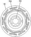
作为优选,所述钉孔共有九组,相邻两组钉孔之间的距离和角度均相同,所述整形孔共有九组,九组整形孔分别与九组钉孔对应。Preferably, there are nine groups of the nail holes, the distance and angle between the adjacent two groups of the nail holes are the same, there are nine groups of the shaping holes, and the nine groups of shaping holes correspond to the nine groups of nail holes respectively.
作为优选,所述定位管、卡块、推杆、抵钉座总成和锥形头的轴线为同一条直线,所述定位孔的圆心位于抵钉座总成的中轴线上且尺寸与推杆的尺寸适配。Preferably, the axes of the positioning tube, the clamping block, the push rod, the anvil seat assembly and the conical head are the same straight line, the center of the positioning hole is located on the central axis of the anvil seat assembly, and the size is the same as that of the push rod. The size of the rod is adapted.
作为优选,初始状态下九个自锁机构在水平方向上的高度相同,均位于限位槽的底部。Preferably, in the initial state, the nine self-locking mechanisms have the same height in the horizontal direction, and are all located at the bottom of the limiting groove.
作为优选,所述抵钉座总成的形状近似于等腰梯形结构,该等腰梯形截面两条腰的角度与锥形头截面的角度相同。Preferably, the shape of the anvil seat assembly is similar to an isosceles trapezoid structure, and the angles of the two sides of the isosceles trapezoid section are the same as the angle of the conical head section.
作为优选,所述抵钉座总成底部的尺寸与卡块顶部的尺寸相同且相互适配。Preferably, the size of the bottom of the anvil seat assembly is the same as the size of the top of the clamping block and is compatible with each other.
与现有技术及产品相比,本发明的有益效果是:Compared with the prior art and products, the beneficial effects of the present invention are:
1、该用于管型吻合器的钉仓组件,通过所述卡块的内壁设置有定位槽结构,所述钉座的外侧设置有定位块结构,该定位块结构与该定位槽结构相适配,由于所述定位管、卡块、推杆、抵钉座总成和锥形头的轴线为同一条直线,所述定位孔的圆心位于抵钉座总成的中轴线上且尺寸与推杆的尺寸适配,将推杆的顶部插接在定位孔的内部,此时可完成该装置的拼接安装,上述过程可使该装置在使用时安装更加方便,减少了前期准备的时间,提高了手术的效率和质量。1. The staple cartridge assembly for tubular stapler is provided with a positioning groove structure through the inner wall of the clamping block, and a positioning block structure is provided on the outer side of the nail base, and the positioning block structure is suitable for the positioning groove structure. Since the axes of the positioning tube, the clamping block, the push rod, the anvil seat assembly and the conical head are the same straight line, the center of the positioning hole is located on the central axis of the anvil seat assembly and the size is the same as that of the push rod. The size of the rod is adapted, and the top of the push rod is inserted into the interior of the positioning hole, and the splicing and installation of the device can be completed at this time. efficiency and quality of surgery.
2、该用于管型吻合器的钉仓组件,通过使活动触点为长条状,所述固定触点与转杆中点的距离小于活动触点的尺寸,并且活动触点的长度小于转杆与钉位之间的距离,所以此时若九个钉位完全缝合充分,则活动触点会与缝合钉接触,此时缝合钉会在于活动触点接触后阻挡其位置,使其无法继续转动,即无法与固定触点接触,此时与固定触点外接的指示灯其线路为断开状态,即表示此时缝合完成且钉位准确,上述过程可实现该装置对缝合状态进行检测提示的目的,避免了因操作者无法直接观察到缝合结果而造成直接取出吻合器的情况,减少了对患者的伤害,提高了手术过程的安全性和可靠性。2. In the staple cartridge assembly for tubular stapler, by making the movable contact in a long strip shape, the distance between the fixed contact and the midpoint of the rotating rod is smaller than the size of the movable contact, and the length of the movable contact is less than The distance between the rotating rod and the nail position, so if the nine nail positions are fully sutured at this time, the movable contact will be in contact with the staple, and the staple will block its position after the movable contact is in contact, making it impossible to Continue to rotate, that is, it cannot be in contact with the fixed contact. At this time, the line of the indicator light connected to the fixed contact is disconnected, which means that the stitching is completed and the stitching position is accurate. The above process can realize the device to detect the stitching status. The purpose of the prompt is to avoid the situation of directly taking out the stapler because the operator cannot directly observe the suturing result, reduce the harm to the patient, and improve the safety and reliability of the operation process.
附图说明Description of drawings
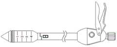
图1为本发明结构连接主视图;Fig. 1 is the front view of the structure connection of the present invention;
图2为本发明结构运动轨迹示意图;Fig. 2 is the schematic diagram of the structural motion trajectory of the present invention;
图3为本发明钉仓总成及内部结构连接示意图;FIG. 3 is a schematic diagram of the nail cartridge assembly and internal structure connection of the present invention;
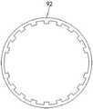
图4为本发明钉仓壳结构示意图;Fig. 4 is the structural schematic diagram of the nail cartridge shell of the present invention;
图5为本发明图3中A处结构放大图;Fig. 5 is an enlarged view of the structure at place A in Fig. 3 of the present invention;
图6为本发明钉座与钉孔连接结构俯视图;6 is a top view of the connection structure of the nail base and the nail hole of the present invention;
图7为本发明定位管结构俯视图;Fig. 7 is the top view of the positioning pipe structure of the present invention;
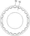
图8为本发明卡块结构俯视图;FIG. 8 is a top view of the block structure of the present invention;
图9为本发明定位管与卡块连接结构俯视图;9 is a top view of the connection structure of the positioning tube and the clamping block according to the present invention;
图10为本发明抵钉座总成、定位孔与整形孔连接结构仰视图;Figure 10 is a bottom view of the connecting structure of the anvil seat assembly, the positioning hole and the shaping hole of the present invention;
图11为本发明推杆、抵钉座总成、拉线与转杆连接结构俯视图;11 is a top view of the connecting structure of the push rod, the anvil seat assembly, the pull wire and the rotating rod of the present invention;
图12为本发明转杆、活动触点与固定触点连接结构示意图;12 is a schematic diagram of the connection structure of the rotating rod, the movable contact and the fixed contact according to the present invention;
图13为本发明转杆、活动触点与固定触点运动轨迹示意图;13 is a schematic diagram of the movement trajectory of the rotating rod, the movable contact and the fixed contact according to the present invention;
图14为本发明推杆与限位槽结构剖切俯视图;Figure 14 is a top view of the structure of the push rod and the limiting groove according to the present invention;
图15为本发明图14中B处结构放大图;Figure 15 is an enlarged view of the structure at B in Figure 14 of the present invention;
图16为本发明限位槽、自锁机构与推杆连接结构示意图;16 is a schematic diagram of the connection structure of the limiting groove, the self-locking mechanism and the push rod according to the present invention;
图17为本发明限位槽、自锁机构与推杆运动轨迹示意图;17 is a schematic diagram of the movement trajectory of the limiting groove, the self-locking mechanism and the push rod according to the present invention;
图18为本发明自锁机构连接结构示意图;Figure 18 is a schematic diagram of the connection structure of the self-locking mechanism of the present invention;
图19为本发明自锁机构运动轨迹示意图。FIG. 19 is a schematic diagram of the movement trajectory of the self-locking mechanism of the present invention.
图中:1-壳体、2-固定手柄、3-击发手柄、4-调节旋钮、5-保险按钮、6-管体、7-锁紧机构、8-钉仓壳、9-钉仓总成、10-拉线、11-转杆、12-活动触点、13-固定触点、14-限位槽、15-自锁机构、91-卡管、92-定位管、93-卡块、94-推杆、95-抵钉座总成、96-锥形头、931-钉座、932-钉孔、951-定位孔、952-整形孔、151-主滑块、152-副滑块、153-活动杆In the figure: 1-shell, 2-fixed handle, 3-fire handle, 4-adjustment knob, 5-safety button, 6-tube body, 7-locking mechanism, 8-sail cartridge shell, 9-sail cartridge total Complete, 10-pull wire, 11-rotating rod, 12-movable contact, 13-fixed contact, 14-limiting slot, 15-self-locking mechanism, 91-card tube, 92-positioning tube, 93-block, 94-Push rod, 95-Nail seat assembly, 96-Conical head, 931-Nail seat, 932-Nail hole, 951-Locating hole, 952-Shaping hole, 151-Main slider, 152-Auxiliary slider , 153-Activity rod
具体实施方式Detailed ways
下面将结合本发明实施例中的附图,对本发明实施例中的技术方案进行清楚、完整地描述,显然,所描述的实施例仅仅是本发明一部分实施例,而不是全部的实施例。基于本发明中的实施例,本领域普通技术人员在没有做出创造性劳动前提下所获得的所有其他实施例,都属于本发明保护的范围。The technical solutions in the embodiments of the present invention will be clearly and completely described below with reference to the accompanying drawings in the embodiments of the present invention. Obviously, the described embodiments are only a part of the embodiments of the present invention, but not all of the embodiments. Based on the embodiments of the present invention, all other embodiments obtained by those of ordinary skill in the art without creative efforts shall fall within the protection scope of the present invention.
请参阅图1-19:See Figure 1-19:
该用于管型吻合器的钉仓组件,包括壳体1、固定手柄2、击发手柄3、调节旋钮4、保险按钮5、管体6、锁紧机构7、钉仓壳8、钉仓总成9、拉线10、转杆11、活动触点12、固定触点13、限位槽14和自锁机构15。The staple cartridge assembly for a tubular stapler includes a
其中:钉仓总成9包括卡管91、定位管92、卡块93、推杆94、抵钉座总成95、锥形头96、钉座931、钉孔932、定位孔951和整形孔952。Wherein: the nail cartridge assembly 9 includes a clamping
其中:自锁机构15包括主滑块151、副滑块152和活动杆153。Wherein: the self-locking
上述各结构的初始位置及连接关系如下:The initial positions and connection relationships of the above structures are as follows:
壳体1的外侧固定连接有固定手柄2,固定手柄2的外侧活动连接有击发手柄3,壳体1的右侧活动连接有调节旋钮4,壳体1的表面设置有保险按钮5,壳体1的左侧活动连接有管体6,管体6的表面镶嵌有锁紧按钮7,管体6远离壳体1的一端活动连接有钉仓壳8,钉仓壳8的内部活动连接有钉仓总成9。The outer side of the
钉仓总成9包括卡管91,卡管91的顶部活动连接有定位管92,定位管92的顶部活动连接有卡块93,定位管92的内部活动连接有推杆94,推杆94的顶部活动连接有抵钉座总成95,抵钉座总成95的顶部活动连接有锥形头96;The staple cartridge assembly 9 includes a clamping
卡块93的内部活动连接有钉座931,钉座931的表面开设有钉孔932。A
抵钉座总成95的内部设置有定位孔951,抵钉座总成95的表面固定连接有整形孔952。A
推杆94的外侧活动连接有拉线10,拉线10远离推杆94的一端活动连接有转杆11,转杆11的表面活动连接有活动触点12,转杆11的外侧活动连接有固定触点13,推杆94的外侧开设有限位槽14,限位槽14的内部活动连接有自锁机构15。A
自锁机构15包括主滑块151,主滑块151的内部活动连接有副滑块152,副滑块152的正面活动连接有活动杆153。The self-locking
其中:in:
a、管体6的内部设置有连杆,调节旋钮4与该连杆的右端活动连接,该连杆的左端与推杆94活动连接,抵钉座总成95的形状近似于等腰梯形结构,该等腰梯形截面两条腰的角度与锥形头96截面的角度相同,抵钉座总成95底部的尺寸与卡块93顶部的尺寸相同且相互适配。a. A connecting rod is arranged inside the pipe body 6, the
b、钉仓壳8的外侧设置有刻度尺,相邻两个标数之间的距离相同,钉仓壳8的形状为圆柱形且轴线与管体6的轴线为同一直线,初始状态下九个自锁机构15在水平方向上的高度相同,均位于限位槽14的底部。b. A scale is arranged on the outside of the
c、活动触点12为长条状,固定触点13与转杆11中点的距离小于活动触点12的尺寸,定位管92、卡块93、推杆94、抵钉座总成95和锥形头96的轴线为同一条直线,定位孔951的圆心位于抵钉座总成95的中轴线上且尺寸与推杆94的尺寸适配。c. The
其中:in:
d、转杆11和拉线10均有九个,九个转杆11以抵钉座总成95的圆心为参照呈均匀分布,即相邻两个转杆11之间的距离和角度均相同,九个转杆11分别与九个拉线10对应,九个拉线10远离转杆11的一端分别与九个副滑块152活动连接,钉孔932共有九组,相邻两组钉孔932之间的距离和角度均相同,整形孔952共有九组,九组整形孔952分别与九组钉孔932对应。d. There are nine
e、限位槽14的数量为九个,相邻两个限位槽14之间的距离和角度均相同,自锁机构15共有九个,九个自锁机构15分别位于九个限位槽14的内部且与其滑动连接,卡块93的内壁设置有定位槽结构,钉座931的外侧设置有定位块结构,该定位块结构与该定位槽结构相适配。e. The number of
f、限位槽14的内部设置有齿牙,活动杆153共有两个,两个活动杆153之间为铰接状态且铰接点位于副滑块152的正面,两个活动杆153之间活动连接有复位弹簧,两个活动杆153远离副滑块152的一端设置有齿状结构,该齿状结构与限位槽14内部的齿牙相适配,定位管92的顶部设置有锯齿状凸块结构,卡块93的底部设置有锯齿状凹块结构,该凸块结构与凹块结构之间相适配。f. There are teeth inside the limiting
在使用时,由于卡块93的内壁设置有定位槽结构,钉座931的外侧设置有定位块结构,该定位块结构与该定位槽结构相适配,由于定位管92、卡块93、推杆94、抵钉座总成95和锥形头96的轴线为同一条直线,定位孔951的圆心位于抵钉座总成95的中轴线上且尺寸与推杆94的尺寸适配,将推杆94的顶部插接在定位孔951的内部,此时可完成该装置的拼接安装。In use, since the inner wall of the clamping
上述结构及过程请参阅图1-10。Please refer to Figure 1-10 for the above structure and process.
假定缝合的钉位共有九个,当组织切除且完成缝合后,由于钉孔932共有九组,相邻两组钉孔932之间的距离和角度均相同,整形孔952共有九组,九组整形孔952分别与九组钉孔932对应,所以此时缝合完成后的状态如图11所示,即九个钉位呈均匀分布。Assuming that there are nine staple positions for suture, after the tissue is removed and the suture is completed, since there are nine groups of
活动触点12为长条状,固定触点13与转杆11中点的距离小于活动触点12的尺寸,并且活动触点12的长度小于转杆11与钉位之间的距离。The
上述结构及过程请参阅图11。Please refer to Figure 11 for the above structure and process.
初始状态下,卡块93和抵钉座总成95之间呈分开状态,当需要对组织进行切除时,二者呈相互接触状态,此时钉座931内部的缝合钉从钉孔932中伸出,穿过待缝合的组织后与整形孔952接触,此时在钉座931的压力作用下缝合钉开始发生弯曲并最终形成“B”字形。In the initial state, the clamping
缝合完成后,使卡块93和钉座931向下旋转移动,由于转杆11和拉线10均有九个,九个转杆11以抵钉座总成95的圆心为参照呈均匀分布,即相邻两个转杆11之间的距离和角度均相同,九个转杆11分别与九个拉线10对应,九个拉线10远离转杆11的一端分别与九个副滑块152活动连接,初始状态下九个自锁机构15在水平方向上的高度相同,均位于限位槽14的底部,所以此时在拉线10的作用下转杆11和活动触点12可发生转动,活动触点12为长条状,固定触点13与转杆11中点的距离小于活动触点12的尺寸,并且活动触点12的长度小于转杆11与钉位之间的距离,所以此时若九个钉位完全缝合充分,则活动触点12会与缝合钉接触,此时缝合钉会在与活动触点12接触后阻挡其位置,使其无法继续转动,即无法与固定触点13接触,此时与固定触点13外接的指示灯其线路为断开状态,即表示此时缝合完成且钉位准确。After the stitching is completed, the clamping
上述结构及过程请参阅图11-13。Please refer to Figure 11-13 for the above structure and process.
由于限位槽14的内部设置有齿牙,活动杆153共有两个,两个活动杆153之间为铰接状态且铰接点位于副滑块152的正面,两个活动杆153之间活动连接有复位弹簧,两个活动杆153远离副滑块152的一端设置有齿状结构,该齿状结构与限位槽14内部的齿牙相适配,初始状态下,两个活动杆153在复位弹簧的作用下角度较大,活动杆153的齿状结构与限位槽14内部的齿牙啮合,此时主滑块151和副滑块152在限位槽14内部的位置相对固定,推杆94运动时可带动限位槽14和其内部的主滑块151和副滑块152同步运动。Since there are teeth inside the limiting
由于转杆11通过拉线10与副滑块152活动连接,所以当活动触点12转动至与缝合钉接触时,由于缝合钉限制活动触点12的位置,所以此时拉线10开始对副滑块152施加向上的拉力,此时两个活动杆153之间的角度减小,主滑块151可在限位槽14内部运动,即此时不影响其他结构的运动。Since the rotating
上述结构及过程请参阅图14-19。Please refer to Figure 14-19 for the above structure and process.
以上所述仅为本发明的较佳实施例,并不用以限制本发明,凡在本发明的精神和原则之内,所作的任何修改、等同替换、改进等,均应包含在本发明的保护范围之内。The above descriptions are only preferred embodiments of the present invention, and are not intended to limit the present invention. Any modification, equivalent replacement, improvement, etc. made within the spirit and principle of the present invention shall be included in the protection of the present invention. within the range.
Claims (5)
Priority Applications (1)
| Application Number | Priority Date | Filing Date | Title |
|---|---|---|---|
| CN201910608588.1ACN110215250B (en) | 2019-07-08 | 2019-07-08 | Tubular anastomat |
Applications Claiming Priority (1)
| Application Number | Priority Date | Filing Date | Title |
|---|---|---|---|
| CN201910608588.1ACN110215250B (en) | 2019-07-08 | 2019-07-08 | Tubular anastomat |
Publications (2)
| Publication Number | Publication Date |
|---|---|
| CN110215250A CN110215250A (en) | 2019-09-10 |
| CN110215250Btrue CN110215250B (en) | 2022-04-15 |
Family
ID=67812843
Family Applications (1)
| Application Number | Title | Priority Date | Filing Date |
|---|---|---|---|
| CN201910608588.1AExpired - Fee RelatedCN110215250B (en) | 2019-07-08 | 2019-07-08 | Tubular anastomat |
Country Status (1)
| Country | Link |
|---|---|
| CN (1) | CN110215250B (en) |
Families Citing this family (1)
| Publication number | Priority date | Publication date | Assignee | Title |
|---|---|---|---|---|
| CN112957090B (en)* | 2021-01-29 | 2022-01-21 | 苏州法兰克曼医疗器械有限公司 | Cutting anastomat with driving mechanism |
Citations (4)
| Publication number | Priority date | Publication date | Assignee | Title |
|---|---|---|---|---|
| CN204636450U (en)* | 2015-02-27 | 2015-09-16 | 郝博 | A kind of nail supporting base assembly for tube type anastomat |
| CN107951524A (en)* | 2017-12-13 | 2018-04-24 | 山东省医学科学院附属医院 | A kind of dragline type assembly tool of magnetic force stapler |
| CN109009286A (en)* | 2018-08-26 | 2018-12-18 | 江苏孜航精密五金有限公司 | Disposable arc line shaped Endo-GIA |
| CN109419544A (en)* | 2017-08-31 | 2019-03-05 | 江苏风和医疗器材股份有限公司 | A kind of staple formation method |
Family Cites Families (1)
| Publication number | Priority date | Publication date | Assignee | Title |
|---|---|---|---|---|
| US9775609B2 (en)* | 2013-08-23 | 2017-10-03 | Ethicon Llc | Tamper proof circuit for surgical instrument battery pack |
- 2019
- 2019-07-08CNCN201910608588.1Apatent/CN110215250B/ennot_activeExpired - Fee Related
Patent Citations (4)
| Publication number | Priority date | Publication date | Assignee | Title |
|---|---|---|---|---|
| CN204636450U (en)* | 2015-02-27 | 2015-09-16 | 郝博 | A kind of nail supporting base assembly for tube type anastomat |
| CN109419544A (en)* | 2017-08-31 | 2019-03-05 | 江苏风和医疗器材股份有限公司 | A kind of staple formation method |
| CN107951524A (en)* | 2017-12-13 | 2018-04-24 | 山东省医学科学院附属医院 | A kind of dragline type assembly tool of magnetic force stapler |
| CN109009286A (en)* | 2018-08-26 | 2018-12-18 | 江苏孜航精密五金有限公司 | Disposable arc line shaped Endo-GIA |
Also Published As
| Publication number | Publication date |
|---|---|
| CN110215250A (en) | 2019-09-10 |
Similar Documents
| Publication | Publication Date | Title |
|---|---|---|
| CN101584596B (en) | A disposable loading unit for a surgery sewing equipment | |
| JP4237488B2 (en) | Endoscopic stapler | |
| JP5377827B2 (en) | Surgical stapling instrument incorporating multiple stroke firing mechanism with flexible rack | |
| MXPA04006766A (en) | Surgical stapling instrument incorporating a tapered firing bar for increased flexibility around the articulation joint. | |
| US20070083233A1 (en) | Surgical stapler with an end effector support | |
| BRPI0405209B1 (en) | SURGICAL CLIPPING INSTRUMENT SHOWING MULTIPLE COURSES WITH OPENING LOCK | |
| MX2007012267A (en) | Articulating surgical stapling instrument incorporating a two-piece e-beam firing mechanism. | |
| BRPI0502730B1 (en) | surgical stapler instrument incorporating a multiple stroke firing mechanism that has a rotary transmission | |
| JP2004537364A (en) | Surgical stapler | |
| JP2005028146A (en) | Surgical instrument incorporating articulation mechanism having rotation about longitudinal axis | |
| MXPA06012763A (en) | Lockout mechanisms and surgical instruments including same. | |
| CN111466976B (en) | Staple cartridge for a surgical instrument and surgical instrument | |
| JP2006034975A (en) | Articulating surgical stapling instrument incorporating two-piece e-beam firing mechanism | |
| BRPI0600256B1 (en) | SURGICAL INSTRUMENT | |
| US10945730B2 (en) | Stapling device with selectively advanceable alignment pin | |
| BR112020003029B1 (en) | surgical instrument | |
| CN110638498A (en) | Circular cutting stapler | |
| CN110215250B (en) | Tubular anastomat | |
| CN115568897A (en) | Anastomat with switch locking linkage mechanism | |
| CN110215249B (en) | A staple cartridge assembly for tubular stapler | |
| WO2019128721A1 (en) | Handle assembly and anastomat comprising same | |
| CN108289684A (en) | Anvil assembly and transport system | |
| CN209529235U (en) | Firing lock and stapler | |
| CN111317538B (en) | Firing mechanism and anastomat | |
| CN209529239U (en) | Circular-pipe anastomat |
Legal Events
| Date | Code | Title | Description |
|---|---|---|---|
| PB01 | Publication | ||
| PB01 | Publication | ||
| SE01 | Entry into force of request for substantive examination | ||
| SE01 | Entry into force of request for substantive examination | ||
| CB03 | Change of inventor or designer information | ||
| CB03 | Change of inventor or designer information | Inventor after:Tan Yuqi Inventor after:Bai Haiguang Inventor after:Liu Chang Inventor before:Liu Chang Inventor before:Tan Yuqi Inventor before:Bai Haiguang | |
| CB03 | Change of inventor or designer information | ||
| CB03 | Change of inventor or designer information | Inventor after:Liu Chang Inventor after:Tan Yuqi Inventor after:Bai Haiguang Inventor before:Tan Yuqi Inventor before:Bai Haiguang Inventor before:Liu Chang | |
| GR01 | Patent grant | ||
| GR01 | Patent grant | ||
| CF01 | Termination of patent right due to non-payment of annual fee | ||
| CF01 | Termination of patent right due to non-payment of annual fee | Granted publication date:20220415 |