CN110206629B - Active pre-combustion chamber ignition system for hybrid power engine and combustion system - Google Patents
Active pre-combustion chamber ignition system for hybrid power engine and combustion systemDownload PDFInfo
- Publication number
- CN110206629B CN110206629BCN201910337905.0ACN201910337905ACN110206629BCN 110206629 BCN110206629 BCN 110206629BCN 201910337905 ACN201910337905 ACN 201910337905ACN 110206629 BCN110206629 BCN 110206629B
- Authority
- CN
- China
- Prior art keywords
- oil
- chamber
- air
- outlet
- valve
- Prior art date
- Legal status (The legal status is an assumption and is not a legal conclusion. Google has not performed a legal analysis and makes no representation as to the accuracy of the status listed.)
- Active
Links
Images


Classifications
- F—MECHANICAL ENGINEERING; LIGHTING; HEATING; WEAPONS; BLASTING
- F02—COMBUSTION ENGINES; HOT-GAS OR COMBUSTION-PRODUCT ENGINE PLANTS
- F02B—INTERNAL-COMBUSTION PISTON ENGINES; COMBUSTION ENGINES IN GENERAL
- F02B19/00—Engines characterised by precombustion chambers
- F02B19/10—Engines characterised by precombustion chambers with fuel introduced partly into pre-combustion chamber, and partly into cylinder
- F02B19/1019—Engines characterised by precombustion chambers with fuel introduced partly into pre-combustion chamber, and partly into cylinder with only one pre-combustion chamber
- F02B19/1023—Engines characterised by precombustion chambers with fuel introduced partly into pre-combustion chamber, and partly into cylinder with only one pre-combustion chamber pre-combustion chamber and cylinder being fed with fuel-air mixture(s)
- F—MECHANICAL ENGINEERING; LIGHTING; HEATING; WEAPONS; BLASTING
- F02—COMBUSTION ENGINES; HOT-GAS OR COMBUSTION-PRODUCT ENGINE PLANTS
- F02B—INTERNAL-COMBUSTION PISTON ENGINES; COMBUSTION ENGINES IN GENERAL
- F02B19/00—Engines characterised by precombustion chambers
- F02B19/10—Engines characterised by precombustion chambers with fuel introduced partly into pre-combustion chamber, and partly into cylinder
- F02B19/1019—Engines characterised by precombustion chambers with fuel introduced partly into pre-combustion chamber, and partly into cylinder with only one pre-combustion chamber
- F02B19/108—Engines characterised by precombustion chambers with fuel introduced partly into pre-combustion chamber, and partly into cylinder with only one pre-combustion chamber with fuel injection at least into pre-combustion chamber, i.e. injector mounted directly in the pre-combustion chamber
- F—MECHANICAL ENGINEERING; LIGHTING; HEATING; WEAPONS; BLASTING
- F02—COMBUSTION ENGINES; HOT-GAS OR COMBUSTION-PRODUCT ENGINE PLANTS
- F02B—INTERNAL-COMBUSTION PISTON ENGINES; COMBUSTION ENGINES IN GENERAL
- F02B19/00—Engines characterised by precombustion chambers
- F02B19/16—Chamber shapes or constructions not specific to sub-groups F02B19/02 - F02B19/10
- F02B19/18—Transfer passages between chamber and cylinder
- F—MECHANICAL ENGINEERING; LIGHTING; HEATING; WEAPONS; BLASTING
- F02—COMBUSTION ENGINES; HOT-GAS OR COMBUSTION-PRODUCT ENGINE PLANTS
- F02M—SUPPLYING COMBUSTION ENGINES IN GENERAL WITH COMBUSTIBLE MIXTURES OR CONSTITUENTS THEREOF
- F02M33/00—Other apparatus for treating combustion-air, fuel or fuel-air mixture
- F—MECHANICAL ENGINEERING; LIGHTING; HEATING; WEAPONS; BLASTING
- F02—COMBUSTION ENGINES; HOT-GAS OR COMBUSTION-PRODUCT ENGINE PLANTS
- F02M—SUPPLYING COMBUSTION ENGINES IN GENERAL WITH COMBUSTIBLE MIXTURES OR CONSTITUENTS THEREOF
- F02M37/00—Apparatus or systems for feeding liquid fuel from storage containers to carburettors or fuel-injection apparatus; Arrangements for purifying liquid fuel specially adapted for, or arranged on, internal-combustion engines
- F02M37/0047—Layout or arrangement of systems for feeding fuel
- F—MECHANICAL ENGINEERING; LIGHTING; HEATING; WEAPONS; BLASTING
- F02—COMBUSTION ENGINES; HOT-GAS OR COMBUSTION-PRODUCT ENGINE PLANTS
- F02M—SUPPLYING COMBUSTION ENGINES IN GENERAL WITH COMBUSTIBLE MIXTURES OR CONSTITUENTS THEREOF
- F02M51/00—Fuel-injection apparatus characterised by being operated electrically
- F02M51/06—Injectors peculiar thereto with means directly operating the valve needle
- F02M51/061—Injectors peculiar thereto with means directly operating the valve needle using electromagnetic operating means
- F—MECHANICAL ENGINEERING; LIGHTING; HEATING; WEAPONS; BLASTING
- F02—COMBUSTION ENGINES; HOT-GAS OR COMBUSTION-PRODUCT ENGINE PLANTS
- F02M—SUPPLYING COMBUSTION ENGINES IN GENERAL WITH COMBUSTIBLE MIXTURES OR CONSTITUENTS THEREOF
- F02M61/00—Fuel-injectors not provided for in groups F02M39/00 - F02M57/00 or F02M67/00
- F02M61/04—Fuel-injectors not provided for in groups F02M39/00 - F02M57/00 or F02M67/00 having valves, e.g. having a plurality of valves in series
- F02M61/10—Other injectors with elongated valve bodies, i.e. of needle-valve type
- F—MECHANICAL ENGINEERING; LIGHTING; HEATING; WEAPONS; BLASTING
- F02—COMBUSTION ENGINES; HOT-GAS OR COMBUSTION-PRODUCT ENGINE PLANTS
- F02M—SUPPLYING COMBUSTION ENGINES IN GENERAL WITH COMBUSTIBLE MIXTURES OR CONSTITUENTS THEREOF
- F02M61/00—Fuel-injectors not provided for in groups F02M39/00 - F02M57/00 or F02M67/00
- F02M61/14—Arrangements of injectors with respect to engines; Mounting of injectors
- F02M61/145—Arrangements of injectors with respect to engines; Mounting of injectors the injection nozzle opening into the air intake conduit
- F—MECHANICAL ENGINEERING; LIGHTING; HEATING; WEAPONS; BLASTING
- F02—COMBUSTION ENGINES; HOT-GAS OR COMBUSTION-PRODUCT ENGINE PLANTS
- F02M—SUPPLYING COMBUSTION ENGINES IN GENERAL WITH COMBUSTIBLE MIXTURES OR CONSTITUENTS THEREOF
- F02M61/00—Fuel-injectors not provided for in groups F02M39/00 - F02M57/00 or F02M67/00
- F02M61/16—Details not provided for in, or of interest apart from, the apparatus of groups F02M61/02 - F02M61/14
- F02M61/18—Injection nozzles, e.g. having valve seats; Details of valve member seated ends, not otherwise provided for
- F02M61/1886—Details of valve seats not covered by groups F02M61/1866 - F02M61/188
- F—MECHANICAL ENGINEERING; LIGHTING; HEATING; WEAPONS; BLASTING
- F02—COMBUSTION ENGINES; HOT-GAS OR COMBUSTION-PRODUCT ENGINE PLANTS
- F02M—SUPPLYING COMBUSTION ENGINES IN GENERAL WITH COMBUSTIBLE MIXTURES OR CONSTITUENTS THEREOF
- F02M61/00—Fuel-injectors not provided for in groups F02M39/00 - F02M57/00 or F02M67/00
- F02M61/16—Details not provided for in, or of interest apart from, the apparatus of groups F02M61/02 - F02M61/14
- F02M61/18—Injection nozzles, e.g. having valve seats; Details of valve member seated ends, not otherwise provided for
- F02M61/1893—Details of valve member ends not covered by groups F02M61/1866 - F02M61/188
- Y—GENERAL TAGGING OF NEW TECHNOLOGICAL DEVELOPMENTS; GENERAL TAGGING OF CROSS-SECTIONAL TECHNOLOGIES SPANNING OVER SEVERAL SECTIONS OF THE IPC; TECHNICAL SUBJECTS COVERED BY FORMER USPC CROSS-REFERENCE ART COLLECTIONS [XRACs] AND DIGESTS
- Y02—TECHNOLOGIES OR APPLICATIONS FOR MITIGATION OR ADAPTATION AGAINST CLIMATE CHANGE
- Y02T—CLIMATE CHANGE MITIGATION TECHNOLOGIES RELATED TO TRANSPORTATION
- Y02T10/00—Road transport of goods or passengers
- Y02T10/10—Internal combustion engine [ICE] based vehicles
- Y02T10/12—Improving ICE efficiencies
Landscapes
- Engineering & Computer Science (AREA)
- Chemical & Material Sciences (AREA)
- Combustion & Propulsion (AREA)
- Mechanical Engineering (AREA)
- General Engineering & Computer Science (AREA)
- Physics & Mathematics (AREA)
- Electromagnetism (AREA)
- Combustion Methods Of Internal-Combustion Engines (AREA)
Abstract
Description
Translated fromChinese技术领域technical field
本发明涉及发动机点火装置技术领域,尤其涉及一种用于混合动力发动机的主动预燃室点火系统及燃烧系统。The invention relates to the technical field of engine ignition devices, in particular to an active pre-chamber ignition system and a combustion system for a hybrid engine.
背景技术Background technique
随着能源与环境问题的日益突出,人们的环保及节能意识也越来越强。车辆作为日常的交通工具,由于保有量巨大,所产生的排放不同忽视。世界各国针对车辆的排放和油耗法规越来越严格,内燃机作为车辆的主要动力源,也面临着严峻的转型升级的挑战。只有不断提高内燃机自身的品质,积极调整配合电气化程度越来越高的动力总成,才能获得更强大的生命力。With the increasingly prominent energy and environmental issues, people's awareness of environmental protection and energy conservation is also growing stronger. Vehicles are used as daily means of transportation. Due to the huge number of vehicles, the emissions generated are different and ignored. As the emission and fuel consumption regulations of vehicles in various countries in the world are becoming more and more strict, the internal combustion engine, as the main power source of vehicles, is also facing severe challenges of transformation and upgrading. Only by continuously improving the quality of the internal combustion engine itself and actively adjusting and cooperating with the powertrain with an increasingly high degree of electrification, can a stronger vitality be achieved.
混动机技术的不断成熟给内燃机的发展带来了新的机遇。对内燃机而言,高效的运行区间是局限的。传统的内燃机需要全工况运行,并且大部分工况是运行在效率相对低下的非经济油耗区,而混动机技术的发展使内燃机摆脱了全工况运行的使命,通过内燃机和电机的配合,使内燃机仅工作在“点”工况、“线”工况,保证了内燃机运行在理想的经济油耗区域,因此混动改变了传统发动机,而发动机也依托混动专职工作在高效的区域成为了高效的混动专用发动机。在这个前提下,追求内燃机最高热效率有了更实际的意义。The continuous maturity of hybrid engine technology has brought new opportunities for the development of internal combustion engines. For internal combustion engines, the efficient operating range is limited. The traditional internal combustion engine needs to run under all working conditions, and most of the working conditions are operated in the non-economic fuel consumption area with relatively low efficiency. The development of hybrid engine technology has freed the internal combustion engine from the mission of running under all working conditions. Through the cooperation of the internal combustion engine and the motor, The internal combustion engine only works in the "point" and "line" operating conditions, which ensures that the internal combustion engine runs in the ideal economic fuel consumption area. Therefore, the hybrid has changed the traditional engine, and the engine also relies on the hybrid to work full-time in an efficient area. Efficient hybrid-specific engine. Under this premise, the pursuit of the highest thermal efficiency of internal combustion engines has more practical significance.
当前实现专用发动机50%甚至更高热效率的技术之一就是稀燃,即通过采用稀空燃比的燃烧。传统的火花塞点火由于点火能量不足难以在高湍流、超稀混合气的情况下实现稳定点火;传统火花塞点火存在点火能量的上限并且容易对放电电极产生侵蚀;主动预燃室点火是一种有效拓展混合气稀燃极限,实现稳定燃烧的点火方式。主动预燃室点火系统是面向未来的点火方式,当前的主动预燃室点火方案通过适配件分别将喷油器和火花塞实现耦合,尺寸较大,导致对当前高度集成的发动机缸盖改动较大,而且由于预燃室容积较小,当前的主动预燃室方案中,喷油器同预燃室的适配性较差,过量的燃油喷射,造成燃烧不完全产生的碳烟随着时间的积累有堵塞预燃室喷孔的风险。One of the current technologies to achieve 50% or more thermal efficiency of dedicated engines is lean burn, ie by using a lean air-fuel ratio. Traditional spark plug ignition is difficult to achieve stable ignition in the case of high turbulence and ultra-lean mixture due to insufficient ignition energy; traditional spark plug ignition has an upper limit of ignition energy and is easy to erode the discharge electrode; active pre-chamber ignition is an effective expansion The lean-burn limit of the mixture is an ignition method that realizes stable combustion. The active pre-combustion chamber ignition system is a future-oriented ignition method. The current active pre-combustion chamber ignition scheme couples the injector and the spark plug respectively through adapters, and the size is large, which leads to relatively large changes to the current highly integrated engine cylinder head. In addition, due to the small volume of the pre-combustion chamber, in the current active pre-combustion chamber scheme, the adaptability of the injector to the pre-combustion chamber is poor, and excessive fuel injection will cause the soot generated by incomplete combustion over time. The build-up of , there is a risk of clogging the pre-chamber nozzles.
发明内容SUMMARY OF THE INVENTION
本发明实施例提供一种用于混合动力发动机的主动预燃室点火系统及燃烧系统,用以解决现有主动预燃室点火系统中预燃室尺寸较大、喷油雾化差、喷油湿壁、点火及燃烧不稳定性的问题。Embodiments of the present invention provide an active pre-chamber ignition system and a combustion system for a hybrid engine, which are used to solve the problems of large pre-chamber size, poor fuel injection atomization, and fuel injection in the existing active pre-chamber ignition system. Problems with wet walls, ignition and combustion instability.
本发明实施例提供一种用于混合动力发动机的主动预燃室点火系统,包括预燃室和设置于所述预燃室上的火花塞,还包括供油管路、供气管路、油气混合室和设置于所述预燃室上的喷射阀,所述供油管路连接于所述油气混合室的进油口,所述供气管路连接于所述油气混合室的进气口,所述油气混合室用于将燃油和空气混合后,经所述喷射阀的出口喷射至所述预燃室内。Embodiments of the present invention provide an active pre-combustion chamber ignition system for a hybrid engine, which includes a pre-combustion chamber, a spark plug arranged on the pre-combustion chamber, and an oil supply pipeline, an air supply pipeline, and an oil-gas mixing chamber. and an injection valve arranged on the pre-combustion chamber, the oil supply pipeline is connected to the oil inlet of the oil-air mixing chamber, the air supply pipeline is connected to the air inlet of the oil-air mixing chamber, the The oil-gas mixing chamber is used for mixing fuel and air, and then injecting the fuel into the pre-combustion chamber through the outlet of the injection valve.
其中,所述油气混合室包括设置于所述预燃室外的雾化箱,所述供油管路的出口通过雾化喷油器连接于所述雾化箱的进油口,所述供气管路的出口连接于所述雾化箱的进气口,所述供气管路上设有空气电磁阀,所述雾化箱的混合气出口通过混合气单向阀连接于所述喷射阀的进口,所述喷射阀的出口连通于所述预燃室。Wherein, the oil-gas mixing chamber includes an atomization box disposed outside the pre-combustion chamber, the outlet of the oil supply pipeline is connected to the oil inlet of the atomization box through an atomization fuel injector, and the air supply pipe The outlet of the road is connected to the air inlet of the atomizing box, the air supply pipeline is provided with an air solenoid valve, and the mixed gas outlet of the atomizing box is connected to the inlet of the injection valve through the mixed gas check valve, The outlet of the injection valve communicates with the pre-combustion chamber.
其中,沿所述雾化箱的长度方向间隔设有多个扰流板,多个所述扰流板依次交叉设置在所述雾化箱相对的两个内壁上。Wherein, a plurality of spoilers are arranged at intervals along the length direction of the atomizing box, and the plurality of spoilers are arranged in sequence on two opposite inner walls of the atomizing box.
其中,所述雾化箱的外壁设有电加热管和/或连通于发动机冷却液系统的循环加热管路。Wherein, the outer wall of the atomization box is provided with an electric heating pipe and/or a circulating heating pipe connected to the engine coolant system.
其中,所述喷射阀包括阀杆、阀体和控制机构,所述阀体上设有连通于所述预燃室的出口,所述阀体的出口与所述混合气出口相连通;所述阀杆的一端抵接于所述阀体的出口,以封闭所述阀体的出口;所述控制机构连接于所述阀杆的另一端,用于推动所述阀杆朝向所述预燃室内移动,以打开或关闭所述阀体的出口。Wherein, the injection valve includes a valve stem, a valve body and a control mechanism, the valve body is provided with an outlet connected to the pre-combustion chamber, and the outlet of the valve body is communicated with the mixture outlet; the One end of the valve stem abuts against the outlet of the valve body to close the outlet of the valve body; the control mechanism is connected to the other end of the valve stem for pushing the valve stem toward the pre-combustion chamber move to open or close the outlet of the valve body.
其中,所述喷射阀包括阀杆、阀体和控制机构,所述阀体上设有连接于所述供油管路的进油通道、连接于所述供气管路的进气通道以及连通于所述预燃室的出口;所述控制机构连接于所述阀杆的顶部,用于推动所述阀杆移动,以使所述喷射阀在封闭状态和打开状态之间转化;Wherein, the injection valve includes a valve stem, a valve body and a control mechanism, and the valve body is provided with an oil inlet channel connected to the oil supply pipeline, an inlet channel connected to the air supply pipeline, and an inlet channel connected to the gas supply pipeline. the outlet of the pre-combustion chamber; the control mechanism is connected to the top of the valve stem for pushing the valve stem to move, so that the injection valve is converted between a closed state and an open state;
所述油气混合室设于所述喷射阀的内部,所述油气混合室包括相互隔离的油腔和气腔,所述油腔和所述气腔由上至下依次设置于所述阀杆的中部;所述油腔的进口连通于所述进油通道,所述气腔连通于所述进气通道;The oil-gas mixing chamber is arranged inside the injection valve, and the oil-gas mixing chamber includes an oil cavity and an air cavity that are isolated from each other, and the oil cavity and the air cavity are sequentially arranged in the middle of the valve stem from top to bottom. ; The inlet of the oil chamber is communicated with the oil inlet passage, and the air chamber is communicated with the inlet passage;
当所述喷射阀处于封闭状态时,所述油腔的出口抵接于所述阀体,所述阀杆的底端抵接于所述阀体的出口;当所述喷射阀处于打开状态时,所述阀杆的底部与所述阀体的出口之间形成间隙,所述油腔的出口、所述进气通道、所述气腔和所述间隙之间相互连通。When the injection valve is in a closed state, the outlet of the oil chamber is in contact with the valve body, and the bottom end of the valve rod is in contact with the outlet of the valve body; when the injection valve is in an open state , a gap is formed between the bottom of the valve stem and the outlet of the valve body, and the outlet of the oil chamber, the intake passage, the air chamber and the gap communicate with each other.
其中,所述火花塞和所述喷射阀相对布置于所述预燃室的顶部,所述火花塞的点火端和所述喷射阀的出口均位于所述预燃室内,所述预燃室的底部沿所述预燃室的周向设有多个射流口。Wherein, the spark plug and the injection valve are arranged opposite to the top of the pre-combustion chamber, the ignition end of the spark plug and the outlet of the injection valve are both located in the pre-combustion chamber, and the bottom of the pre-combustion chamber is along the The pre-combustion chamber is provided with a plurality of jet ports in the circumferential direction.
其中,所述喷射阀呈倾斜布置,所述喷射阀的出口包括设于所述喷射阀的底端的中间的第一喷孔和沿所述喷射阀的周向设置的多个第二喷孔;所述多个射流口包括一个排气侧射流口,所述排气侧射流口的直径大于其他的射流口的直径;所述第一喷孔正对所述排气侧射流口。Wherein, the injection valve is arranged obliquely, and the outlet of the injection valve includes a first injection hole provided in the middle of the bottom end of the injection valve and a plurality of second injection holes arranged along the circumferential direction of the injection valve; The plurality of jet ports include an exhaust side jet port, and the diameter of the exhaust side jet port is larger than that of other jet ports; the first injection hole is facing the exhaust side jet port.
其中,所述控制机构包括衔铁、弹簧和线圈,所述衔铁固定于所述阀杆的上端,所述弹簧设于所述衔铁的下方,以将所述衔铁向上顶压;所述衔铁的下方还设有线圈,所述线圈用于在通电时向下吸引所述衔铁。Wherein, the control mechanism includes an armature, a spring and a coil, the armature is fixed on the upper end of the valve stem, and the spring is arranged below the armature to press the armature upward; the lower part of the armature There is also a coil for pulling down the armature when energized.
本发明实施例还提供一种用于混合动力发动机的燃烧系统,包括上述主动预燃室点火系统,还包括设置于所述预燃室的下方的主燃室,所述主燃室还连通有进气道和排气道;所述进气道上设有进气喷油器,所述进气喷油器的进口连接于所述供油管路,所述进气喷油器的出口连通于所述进气道。An embodiment of the present invention further provides a combustion system for a hybrid engine, which includes the above-mentioned active pre-combustion chamber ignition system, and also includes a main combustion chamber disposed below the pre-combustion chamber, and the main combustion chamber is further communicated with an intake port and an exhaust port; an intake fuel injector is arranged on the intake port, the inlet of the intake fuel injector is connected to the oil supply pipeline, and the outlet of the intake fuel injector is connected to the the air intake.
本发明实施例提供的用于混合动力发动机的主动预燃室点火系统及燃烧系统,其中主动预燃室点火系统包括预燃室和设置在预燃室上的火花塞,还包括供油管路、供气管路、油气混合室和设置在预燃室上的喷射阀,其中供油管路用于连通外界的供油装置,供气管路用于连通外界的压缩空气装置。供油管路将燃油导入油气混合室,供气管路将高压空气导入油气混合室内,燃油和高压空气再油气混合室的混合均匀后,从混合气出口导出浓混合气,并利用喷射阀将浓混合气喷射进入预燃室,预燃室内的火花塞点燃浓混合气,生成的火焰射流再进入主燃室点燃主燃室内的稀混合气。通过设置油气混合室可以使燃油被充足良好地雾化和气化,从而避免在狭小的预燃室内部进行燃油喷射而造成的湿壁,同时将喷射阀同火花塞集成一体的预燃室方案,使预燃室体积更小、更紧凑且易于布置。该主动预燃室点火系统可实现浓度可控的混合气制备及精确供给,良好的燃油雾化有利于预燃室内混合气的燃烧,减少不完全燃烧产物的产生,是一种拓展汽油机稀燃的有效点火方案,实用性强。An active pre-combustion chamber ignition system and a combustion system for a hybrid engine provided by the embodiments of the present invention, wherein the active pre-combustion chamber ignition system includes a pre-combustion chamber and a spark plug arranged on the pre-combustion chamber, and also includes an oil supply pipeline, An air supply pipeline, an oil-gas mixing chamber and an injection valve arranged on the pre-combustion chamber, wherein the oil supply pipeline is used to communicate with an external oil supply device, and the air supply pipeline is used to communicate with an external compressed air device. The fuel supply pipeline introduces the fuel into the oil-gas mixing chamber, and the air supply pipeline introduces the high-pressure air into the oil-gas mixing chamber. After the fuel and the high-pressure air are evenly mixed in the oil-gas mixing chamber, the rich mixture is exported from the mixture outlet, and the rich mixture is discharged by the injection valve. The mixture is injected into the pre-combustion chamber, the spark plug in the pre-combustion chamber ignites the rich mixture, and the generated flame jet enters the main combustion chamber to ignite the lean mixture in the main combustion chamber. By setting the oil-air mixing chamber, the fuel can be sufficiently well atomized and vaporized, so as to avoid the wet wall caused by fuel injection in the narrow pre-combustion chamber. The pre-chamber is smaller, more compact and easier to arrange. The active pre-combustion chamber ignition system can realize the preparation and accurate supply of the mixture with controllable concentration, good fuel atomization is conducive to the combustion of the mixture in the pre-combustion chamber, and reduces the generation of incomplete combustion products. An effective ignition scheme with strong practicability.
附图说明Description of drawings
为了更清楚地说明本发明实施例或现有技术中的技术方案,下面将对实施例或现有技术描述中所需要使用的附图作一简单地介绍,显而易见地,下面描述中的附图是本发明的一些实施例,对于本领域普通技术人员来讲,在不付出创造性劳动的前提下,还可以根据这些附图获得其他的附图。In order to more clearly illustrate the embodiments of the present invention or the technical solutions in the prior art, the following briefly introduces the accompanying drawings that need to be used in the description of the embodiments or the prior art. Obviously, the accompanying drawings in the following description These are some embodiments of the present invention. For those of ordinary skill in the art, other drawings can also be obtained according to these drawings without creative efforts.
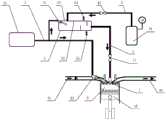
图1是本发明实施例中的一种用于混合动力发动机的燃烧系统的示意图;1 is a schematic diagram of a combustion system for a hybrid engine in an embodiment of the present invention;
图2是图1中的预燃室、火花塞和喷射阀的剖视图;FIG. 2 is a cross-sectional view of the pre-chamber, spark plug and injection valve of FIG. 1;
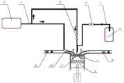
图3是本发明实施例中的另一种用于混合动力发动机的燃烧系统的示意图;3 is a schematic diagram of another combustion system for a hybrid engine in an embodiment of the present invention;
图4是图3中的预燃室、火花塞和喷射阀的剖视图;4 is a cross-sectional view of the pre-chamber, spark plug and injection valve of FIG. 3;
图5是图4中的喷射阀的局部放大图,其中a图是喷射阀处于封闭状态时示意图,b图是喷射阀处于打开状态时示意图;Fig. 5 is a partial enlarged view of the injection valve in Fig. 4, wherein Fig. a is a schematic diagram when the injection valve is in a closed state, and Fig. b is a schematic diagram when the injection valve is in an open state;
图6是本发明实施例中的一种喷射阀和火花塞耦合布置于预燃室的示意图,其中a图是预燃室的仰视图,b图是预燃室的剖视图;6 is a schematic diagram of an injection valve and a spark plug being coupled and arranged in a pre-chamber according to an embodiment of the present invention, wherein Figure a is a bottom view of the pre-chamber, and Figure b is a cross-sectional view of the pre-chamber;
附图标记说明:Description of reference numbers:
1:预燃室; 11:射流口; 12:排气侧射流口;1: Pre-combustion chamber; 11: Jet port; 12: Exhaust side jet port;
2:火花塞; 3:供油管路; 31:油箱;2: Spark plug; 3: Oil supply pipeline; 31: Fuel tank;
32:供油单向阀; 4:供气管路; 41:压缩空气瓶;32: Oil supply check valve; 4: Air supply pipeline; 41: Compressed air bottle;
42:空气电磁阀; 5:雾化箱; 51:雾化喷油器;42: Air solenoid valve; 5: Atomizing box; 51: Atomizing fuel injector;
52:扰流板; 53:压力传感器; 54:泄压阀;52: spoiler; 53: pressure sensor; 54: pressure relief valve;
55:泄流阀; 6:喷射阀; 61:阀杆;55: Relief valve; 6: Injection valve; 61: Valve stem;
62:阀体; 621:阀体的出口; 622:进油通道;62: valve body; 621: outlet of valve body; 622: oil inlet channel;
623:进气通道; 63:控制机构; 631:导线;623: Intake passage; 63: Control mechanism; 631: Wire;
632:第一弹簧; 633:衔铁; 634:第二弹簧;632: first spring; 633: armature; 634: second spring;
635:线圈; 64:喷射阀壳体; 641:第一喷孔;635: Coil; 64: Injection valve housing; 641: First injection hole;
642:第二喷孔; 65:第一喷孔油束; 66:第二喷孔油束;642: The second nozzle hole; 65: The first nozzle hole oil beam; 66: The second nozzle hole oil beam;
7:混合气管路; 71:混合气单向阀; 8:油气混合腔;7: Mixed gas pipeline; 71: Mixed gas check valve; 8: Oil and gas mixing chamber;
81:油腔; 811:环形油腔; 812:柱形油腔;81: oil chamber; 811: annular oil chamber; 812: cylindrical oil chamber;
813:油腔的出口; 82:气腔; 83:间隙;813: Outlet of oil chamber; 82: Air chamber; 83: Clearance;
9:主燃室; 91:进气道; 92:排气道;9: Main combustion chamber; 91: Intake port; 92: Exhaust port;
93:进气喷油器; 10:发动机。93: Intake injector; 10: Engine.
具体实施方式Detailed ways
为使本发明实施例的目的、技术方案和优点更加清楚,下面将结合本发明实施例中的附图,对本发明实施例中的技术方案进行清楚、完整地描述,显然,所描述的实施例是本发明一部分实施例,而不是全部的实施例。基于本发明中的实施例,本领域普通技术人员在没有做出创造性劳动前提下所获得的所有其他实施例,都属于本发明保护的范围。In order to make the purposes, technical solutions and advantages of the embodiments of the present invention clearer, the technical solutions in the embodiments of the present invention will be clearly and completely described below with reference to the accompanying drawings in the embodiments of the present invention. Obviously, the described embodiments These are some embodiments of the present invention, but not all embodiments. Based on the embodiments of the present invention, all other embodiments obtained by those of ordinary skill in the art without creative efforts shall fall within the protection scope of the present invention.
在本发明实施例的描述中,需要说明的是,除非另有明确的规定和限定,术语“第一”“第二”是为了清楚说明产品部件进行的编号,不代表任何实质性区别。“上”“下”“左”“右”的方向均以附图所示方向为准。对于本领域的普通技术人员而言,可以根据具体情况理解上述术语在本发明实施例中的具体含义。In the description of the embodiments of the present invention, it should be noted that, unless otherwise expressly specified and limited, the terms "first" and "second" are used to clearly describe the numbering of product components and do not represent any substantial difference. The directions of "up", "down", "left" and "right" are based on the directions shown in the drawings. Those of ordinary skill in the art can understand the specific meanings of the above terms in the embodiments of the present invention according to specific situations.
需要说明的是,除非另有明确的规定和限定,术语“连接”应做广义理解,例如,可以是直接相连,也可以通过中间媒介间接相连。对于本领域的普通技术人员而言,可以具体情况理解上述术语在发明实施例中的具体含义。It should be noted that, unless otherwise expressly specified and limited, the term "connection" should be understood in a broad sense, for example, it may be directly connected or indirectly connected through an intermediate medium. For those of ordinary skill in the art, the specific meanings of the above terms in the embodiments of the invention can be understood in specific situations.
图1是本发明实施例中的一种用于混合动力发动机的燃烧系统的示意图,图2是图1中的预燃室、火花塞和喷射阀的剖视图,如图1和图2所示,本发明实施例提供的一种用于混合动力发动机的主动预燃室点火系统,包括预燃室1和设置于预燃室1上的火花塞2,还包括供油管路3、供气管路4、油气混合室和设置于预燃室1上的喷射阀6,供油管路3连接于油气混合室的进油口,供气管路4连接于油气混合室的进气口,油气混合室的混合气出口通过喷射阀6连接于预燃室1。1 is a schematic diagram of a combustion system for a hybrid engine in an embodiment of the present invention, and FIG. 2 is a cross-sectional view of a pre-combustion chamber, a spark plug and an injection valve in FIG. 1 , as shown in FIGS. An active pre-combustion chamber ignition system for a hybrid engine provided by the embodiment of the invention includes a
具体地,火花塞2主要用于点燃油气混合气,可以采用M10或者更小螺纹安装在预燃室1的顶部。火花塞2可以采用准型火花塞、缘体突出型火花塞、电极型火花塞或者极型火花塞,只要满足点火需求即可。喷射阀6可以单向开启,用于连通混合气出口和预燃室1,以将油气混合气喷射进预燃室1内。火花塞2和喷射阀6集成布置于预燃室1的顶部,可以尽可能减少预燃室1的体积尺寸。Specifically, the
供油管路3用于连接外界的供油装置,供油装置可以为汽车的邮箱。供气管路4用于连接外界的压缩空气装置,压缩空气装置可以为压缩空气瓶41,并可由车载的空气压缩机供气。油气混合室将来自于供油管路3的燃油和来自于供气管路4的高压空气进行均匀地混合,形成空燃比小于1的浓混合气,然后经过喷射阀6喷入预燃室1,被火花塞2点燃,形成火焰射流,再进入主燃室9点燃主燃室9内的稀混合气,稀混合气的空燃比大于1。The
本实施例提供的一种用于混合动力发动机的主动预燃室点火系统,包括预燃室和设置在预燃室上的火花塞,还包括供油管路、供气管路、油气混合室和设置在预燃室上的喷射阀,其中供油管路用于连通外界的供油装置,供气管路用于连通外界的压缩空气装置。供油管路将燃油导入油气混合室,供气管路将高压空气导入油气混合室内,燃油和高压空气再油气混合室的混合均匀后,从混合气出口导出浓混合气,并利用喷射阀将浓混合气喷射进入预燃室,预燃室内的火花塞点燃浓混合气,生成的火焰射流再进入主燃室点燃主燃室内的稀混合气。通过设置油气混合室可以使燃油被充足良好地雾化和气化,从而避免在狭小的预燃室内部进行燃油喷射而造成的湿壁,同时将喷射阀同火花塞集成一体的预燃室方案,使预燃室体积更小、更紧凑且易于布置。该主动预燃室点火系统可实现浓度可控的混合气制备及精确供给,良好的燃油雾化有利于预燃室内混合气的燃烧,减少不完全燃烧产物的产生,是一种拓展汽油机稀燃的有效点火方案,实用性强。An active pre-combustion chamber ignition system for a hybrid engine provided in this embodiment includes a pre-combustion chamber and a spark plug arranged on the pre-combustion chamber, and also includes an oil supply pipeline, an air supply pipeline, an oil-gas mixing chamber, and a The injection valve on the pre-combustion chamber, wherein the oil supply pipeline is used to communicate with the external oil supply device, and the air supply pipeline is used to communicate with the external compressed air device. The fuel supply pipeline introduces the fuel into the oil-gas mixing chamber, and the air supply pipeline introduces the high-pressure air into the oil-gas mixing chamber. After the fuel and the high-pressure air are evenly mixed in the oil-gas mixing chamber, the rich mixture is exported from the mixture outlet, and the rich mixture is discharged by the injection valve. The mixture is injected into the pre-combustion chamber, the spark plug in the pre-combustion chamber ignites the rich mixture, and the generated flame jet enters the main combustion chamber to ignite the lean mixture in the main combustion chamber. By setting the oil-air mixing chamber, the fuel can be sufficiently well atomized and vaporized, so as to avoid the wet wall caused by fuel injection in the narrow pre-combustion chamber. The pre-chamber is smaller, more compact and easier to arrange. The active pre-combustion chamber ignition system can realize the preparation and accurate supply of the mixture with controllable concentration, good fuel atomization is conducive to the combustion of the mixture in the pre-combustion chamber, and reduces the generation of incomplete combustion products. An effective ignition scheme with strong practicability.
进一步地,如图1和图2所示,油气混合室包括设置于预燃室1外的雾化箱5,供油管路3通过雾化喷油器51连接于雾化箱5的进油口,供气管路4通过空气电磁阀42连接于雾化箱5的进气口,雾化箱5的混合气出口通过混合气单向阀71连接于喷射阀6的进口,喷射阀6的出口连通于预燃室1。Further, as shown in FIG. 1 and FIG. 2 , the oil-gas mixing chamber includes an
具体地,雾化箱5的容积可设置在500-1000mL之间,雾化箱5可采用耐高温的高分子材料制成。雾化箱5的顶部安装有压力传感器53,压力传感器53用于采集雾化箱5的内部压力。更具体地,还包括系统控制器(图中未示出),空气电磁阀42、雾化喷油器51和压力传感器53均电连接于系统控制器。利用系统控制器可以精确地控制雾化箱5中的浓油气混合气的空燃比。Specifically, the volume of the
在一个具体地实施例中,将混合气的空燃比控制在0.5-1之间的精确值,混合气的标准供给压力控制在2.5bar,压缩空气瓶41可提供2.5bar的稳定压缩空气压力。当雾化箱5内部的压力低于2.3bar时,系统控制器控制空气电磁阀42开启,同时根据压力传感器53的实时反馈信号计算出进入雾化箱5的压缩空气量,然后按照预设的空燃比值,控制雾化喷油器51喷入相应的燃油量。In a specific embodiment, the air-fuel ratio of the mixture is controlled at a precise value between 0.5-1, the standard supply pressure of the mixture is controlled at 2.5bar, and the
雾化箱5的顶部还设有泄压阀54,泄压阀54用于卸掉超过雾化箱5的最大可承受压力的上限的压力,防止雾化箱5超压损坏。在一个具体地实施例中,雾化箱5内部的混合气标准压力为2.5bar,泄压阀54的起跳值为3bar。雾化箱5的底部还设有泄流阀55,泄流阀55用于排出凝结在雾化箱5内的水汽。The top of the
进一步地,如图1所示,雾化箱5的内壁沿雾化箱5的长度方向间隔设有多个扰流板52,多个扰流板52依次交叉设置在雾化箱5相对的两个内壁上。通过扰流板52可以扰动雾化箱5内的气流的流动方向,加速燃油和空气的混合,进而形成更加均匀的混合气,同时还可以减少压缩空气在进气时对混合气出口的影响。Further, as shown in FIG. 1 , the inner wall of the
进一步地,雾化箱5的外壁设有电加热管(图中未示出)和/或连通于发动机冷却液系统的循环加热管路(图中未示出)。具体地,当雾化箱5的外壁同时设置有电加热管和循环加热管路时,在低温冷启动的过程中,系统控制器控制电加热管工作,提高雾化箱5内的温度,提高压缩空气温度,使混合气快速雾化,改善预燃室1内油气雾化效果。Further, the outer wall of the
当暖机过程完成后,系统控制器关闭电加热管,并切换为循环加热管路的加热方式。循环加热管路连通于发动机冷却液管路,因而在发动机10充分热机以后可保持雾化箱5始终处于90℃的恒温条件,进而实现对雾化箱5的持续加热和保温,有助于燃油和压缩空气的进一步混合。When the warm-up process is completed, the system controller turns off the electric heating pipe and switches to the heating mode of the circulating heating pipe. The circulating heating pipeline is connected to the engine coolant pipeline, so after the
进一步地,如图2所示,喷射阀6包括阀杆61、阀体62和控制机构63,阀体62上设有连通于预燃室1的出口,阀体的出口621通过混合气管路7与雾化箱5的混合气出口相连通。阀杆61的下端抵接于阀体的出口621,以封闭阀体的出口621。控制机构63连接于阀杆61的上端,以推动阀杆61朝向预燃室1内移动,打开阀体的出口621。Further, as shown in FIG. 2 , the
具体地,阀杆61包括上部的第一柱体、中部的第二柱体以及下部的圆台,第一柱体连接于控制机构63,第二柱体的外壁套设有阀体62,圆台抵接于阀体的出口621,阀体的出口621为锥形沉头孔,且与圆台相互配合。初始时,圆台抵接于阀体的出口621,进而将混合气管路7的出口封堵住,喷射阀6处于封闭状态;动作时,阀杆61在控制机构63的驱动下向下平移,圆台伸出阀体62一段距离,圆台与阀体的出口621之间形成间隙,混合气可以通过该间隙出流,喷射阀6处于打开状态;动作结束后,阀杆61在控制机构63的驱动下向上复位,圆台重新封堵阀体的出口621,喷射阀6恢复封闭状态。Specifically, the
更进一步地,控制机构63可以采用电磁控制机构,包括衔铁633、第二弹簧634和线圈635,衔铁633固定于阀杆61的上端,第二弹簧634设于衔铁633的下方,第二弹簧634处于压缩状态,因而可以将衔铁633向上顶压,进而将圆台抵紧于阀体的出口621,使喷射阀6封闭。衔铁633的下方还设有线圈635,线圈635用于在通电时向下吸引衔铁633,同时克服第二弹簧634的预紧力,使得衔铁633向下移动,进而带动阀杆61下移,使喷射阀6打开。线圈635可以通过导线631连接于外部的供电装置。Further, the
更进一步地,衔铁633的上方还设有第一弹簧632,第一弹簧632也处于压缩状态,可以将衔铁633向下顶压,且第一弹簧632的预紧力小于第二弹簧634的预紧力,因而初始时衔铁633受到向上的压力,动作时衔铁633受到向下的压力。通过设置两个弹簧可以保证阀杆的平移运动更加稳定。Further, a
如图1所示,本发明实施例还提供一种用于混合动力发动机的燃烧系统,包括上述的主动预燃室点火系统,还包括设置于预燃室1的下方的主燃室9,主燃室9还连通有进气道91和排气道92。进气道91上设有进气喷油器93,进气喷油器93的进口连接于供油管路3,进气喷油器93的出口连通于进气道91。As shown in FIG. 1 , an embodiment of the present invention further provides a combustion system for a hybrid engine, which includes the above-mentioned active pre-combustion chamber ignition system, and also includes a
具体地,进气喷油器93将来自油箱31的燃油喷入发动机10的进气道91,同进气道91中的空气进行混合,形成均质的稀薄混合气。雾化喷油器51和进气喷油器93均采用相同的喷油器,可采用低压喷射。Specifically, the
上述实施例中的燃油和空气在雾化箱中混合后再进入喷射阀,属于预先混合的方式,油气混合室设置于喷射阀的外部。除了预先混合的方式外,还可以采用空气辅助混合的方式,如图3-图5所示,本发明实施例还提供了一种空气辅助混合的主动预燃室点火系统,该实施例与预先混合的主动预燃室点火系统的区别主要在于将油气混合室集成于喷射阀6中。In the above embodiment, the fuel and air are mixed in the atomizing box and then enter the injection valve, which belongs to the pre-mixing method, and the oil-gas mixing chamber is arranged outside the injection valve. In addition to the pre-mixing method, the air-assisted mixing method can also be used. As shown in FIGS. 3 to 5 , an embodiment of the present invention also provides an air-assisted mixing active pre-combustion chamber ignition system. The hybrid active pre-chamber ignition system differs mainly in the integration of the fuel-air mixing chamber in the
具体地,如图4所示,喷射阀6包括阀杆61、阀体62和控制机构63,阀体62上设有连接于供油管路3的进油通道622、连接于供气管路4的进气通道623以及连通于预燃室1的出口。供油管路3上设有供油单向阀32,供气管路4上设有空气电磁阀42。控制机构63连接于阀杆61的顶部,以使喷射阀6在封闭状态和打开状态之间可转化。Specifically, as shown in FIG. 4 , the
油气混合室为油气混合腔8,包括相互隔离的油腔81和气腔82,油腔81和气腔82由上至下依次设置于阀杆61的中部,油腔81的进口连通于进油通道622,气腔82连通于进气通道623。The oil-gas mixing chamber is an oil-
如图5中的a图所示,当喷射阀6处于封闭状态时,油腔的出口813抵接于阀体62,阀杆61的底端抵接于阀体的出口621。As shown in a of FIG. 5 , when the
如图5中的b图所示,当喷射阀6处于打开状态时,阀杆61的底部与阀体的出口621之间形成间隙83,油腔的出口813连通于进气通道623,气腔82同时连通于进气通道623和间隙83。进气压力大于进油压力,因而燃油与压缩空气在气腔82和间隙83中混合后被喷入预燃室1内。As shown in b in FIG. 5 , when the
更具体地,油腔81包括上部的环形油腔811和下部的柱形油腔812。环形油腔811可为沿阀杆61的周向设置在阀杆61中部外侧壁上的凹槽。环形油腔811的外侧连通于进油通道622,进油通道622可为贯穿阀体62侧壁的通道。柱形油腔812可为设置在阀杆61中部段内部的空腔。柱形油腔812的上部沿周向设有多个进油口,并通过进油口连通于环形油腔811。柱形油腔812的下部沿周向设有多个贯穿阀杆61的油腔的出口813,油腔的出口813位于气腔82的上方并间隔一定距离。More specifically, the
当控制机构63不通电时,阀杆61受第二弹簧634向上的预紧力,阀杆61的底端抵接于阀体的出口621,且阀杆61中部段的外侧壁与阀体62的内侧壁相接,使得油腔的出口813被阀体62的内壁封堵,此时油路和气路彼此隔离,喷射阀6处于封闭状态。When the
当控制机构63通电时,线圈635内产生电流,进而产生磁场吸引衔铁633克服第二弹簧634的预紧力,并向下移动,阀杆61的底端下移,伸出阀体62一定距离,燃油经过进油通道622进入环形油腔811,再经过进油口进入柱形油腔812,再经过油腔的出口813喷入气腔82,燃油和压缩空气在气腔82内混合后,经过间隙83喷入预燃室1内。When the
更具体地,在发动机10排气结束至压缩冲程开始的曲轴范围内,控制机构63可通电开启,开启时喷射阀6内部的浓混合气压力大于气缸内压力,浓混合气喷入预燃室1。More specifically, in the crankshaft range from the end of the exhaust of the
另外,油腔的出口813还可以设置在气腔82的下方,且油腔的出口813横向贯通于阀杆61的底部圆台。In addition, the
进一步地,如图6所示,火花塞2和喷射阀6相对布置于预燃室1的顶部,火花塞2的点火端和喷射阀6的出口均位于预燃室1内,预燃室1的底部沿预燃室1的周向设有多个射流口11。另外,预燃室1的底部还可以设有竖直向下的射流口11。Further, as shown in FIG. 6 , the
更进一步地,如图5和图6所示,喷射阀6呈倾斜布置,喷射阀6的出口包括设于喷射阀壳体64的底端的中间的第一喷孔641和沿喷射阀6的周向设置的多个第二喷孔642。多个射流口11包括一个排气侧射流口12,排气侧射流口12的直径大于其他的射流口11的直径。第一喷孔641正对排气侧射流口12。Further, as shown in FIGS. 5 and 6 , the
具体地,第一喷孔641可以产生较大的射流喷雾,第一喷孔油束65贯穿排气侧射流口12进入发动机10的主燃室9,以冷却排气侧,产生的浓混合气可抑制爆震。第二喷孔642喷出的第二喷孔油束66贯穿距较小,用以供给预燃室1内部,在预燃室1内部形成偏浓的混合气。Specifically, the
如图3所示,本发明实施例还提供另一种用于混合动力发动机的燃烧系统,包括上述的主动预燃室点火系统,还包括设置于预燃室1的下方的主燃室9,主燃室9还连通有进气道91和排气道92。进气道91上设有进气喷油器93,进气喷油器93的进口连接于供油管路3,进气喷油器93的出口连通于进气道91。As shown in FIG. 3 , the embodiment of the present invention further provides another combustion system for a hybrid engine, which includes the above-mentioned active pre-combustion chamber ignition system, and also includes a
具体地,进气喷油器93将来自油箱31的燃油喷入发动机10的进气道91,同进气道91中的空气进行混合,形成均质的稀薄混合气。进气喷油器93可采用低压喷射。Specifically, the
在一个具体的实施例中,发动机10在暖机时,主燃室9的稀混合气的空燃比控制在1-1.2之间,预燃室1喷入空燃比小于1的浓混合气,以提高燃烧的稳定性。发动机10完成暖机后,主燃室9的稀混合气的空燃比控制在1.5-2.0之间,预燃室1喷入空燃比小于1的浓混合气,以提高热效率。In a specific embodiment, when the
下面结合本实施例中的燃烧系统的运行方法来具体说明。The following describes the operation method of the combustion system in this embodiment in detail.
发动机10在充分暖机以后(冷却水温大于60℃),运行主动预燃室点火系统,在进气冲程或压缩冲程开始阶段,控制喷射阀6打开,使浓混合气进入预燃室1内部,火花塞2点燃预燃室1内的浓混合气,预燃室1中的浓混合气燃烧产生的高温高压气体,由预燃室1的壁面周向及底部设置的喷孔喷出,形成射流火焰,射流火焰再点燃主燃室9中的稀薄混合气。After the
发动机10缸内的稀混合气由每循环中进气喷油器93的喷油及发动机10的进气混合而成,稀混合气的空燃比可以控制在1.5-2之间的精确值。浓混合气在油气混合室内部由燃油和压缩空气充分混合形成,浓混合气的空燃比可控制在0.5-1之间的精确值,浓混合气的标准供给压力为2.5bar。The lean mixture in the cylinder of the
发动机10在暖机的过程中(冷却水温小于60℃)时,可考虑适当加浓主燃室9内的稀混合气,以保证发动机10在暖机过程中燃烧的稳定性以及减少因燃烧不良带来的有害物质排放。When the
通过以上实施例可以看出,本发明提供的用于混合动力发动机的主动预燃室点火系统及燃烧系统,其中主动预燃室点火系统包括预燃室和设置在预燃室上的火花塞,还包括供油管路、供气管路、油气混合室和设置在预燃室上的喷射阀,其中供油管路用于连通外界的供油装置,供气管路用于连通外界的压缩空气装置。供油管路将燃油导入油气混合室,供气管路将高压空气导入油气混合室内,燃油和高压空气再油气混合室的混合均匀后,从混合气出口导出浓混合气,并利用喷射阀将浓混合气喷射进入预燃室,预燃室内的火花塞点燃浓混合气,生成的火焰射流再进入主燃室点燃主燃室内的稀混合气。通过设置油气混合室可以使燃油被充足良好地雾化和气化,从而避免在狭小的预燃室内部进行燃油喷射而造成的湿壁,同时将喷射阀同火花塞集成一体的预燃室方案,使预燃室体积更小、更紧凑且易于布置。该主动预燃室点火系统可实现浓度可控的混合气制备及精确供给,良好的燃油雾化有利于预燃室内混合气的燃烧,减少不完全燃烧产物的产生,是一种拓展汽油机稀燃的有效点火方案,实用性强。It can be seen from the above embodiments that the present invention provides an active pre-chamber ignition system and a combustion system for a hybrid engine, wherein the active pre-chamber ignition system includes a pre-chamber and a spark plug arranged on the pre-chamber, and also It includes an oil supply pipeline, an air supply pipeline, an oil-gas mixing chamber and an injection valve arranged on the pre-combustion chamber, wherein the oil supply pipeline is used to communicate with the external oil supply device, and the air supply pipeline is used to communicate with the external compressed air device. The fuel supply pipeline introduces the fuel into the oil-gas mixing chamber, and the air supply pipeline introduces the high-pressure air into the oil-gas mixing chamber. After the fuel and the high-pressure air are evenly mixed in the oil-gas mixing chamber, the rich mixture is exported from the mixture outlet, and the rich mixture is discharged by the injection valve. The mixture is injected into the pre-combustion chamber, the spark plug in the pre-combustion chamber ignites the rich mixture, and the generated flame jet enters the main combustion chamber to ignite the lean mixture in the main combustion chamber. By setting the oil-air mixing chamber, the fuel can be sufficiently well atomized and vaporized, so as to avoid the wet wall caused by fuel injection in the narrow pre-combustion chamber. The pre-chamber is smaller, more compact and easier to arrange. The active pre-combustion chamber ignition system can realize the preparation and accurate supply of the mixture with controllable concentration, good fuel atomization is conducive to the combustion of the mixture in the pre-combustion chamber, and reduces the generation of incomplete combustion products. An effective ignition scheme with strong practicability.
最后应说明的是:以上实施例仅用以说明本发明的技术方案,而非对其限制;尽管参照前述实施例对本发明进行了详细的说明,本领域的普通技术人员应当理解:其依然可以对前述各实施例所记载的技术方案进行修改,或者对其中部分技术特征进行等同替换;而这些修改或者替换,并不使相应技术方案的本质脱离本发明各实施例技术方案的精神和范围。Finally, it should be noted that the above embodiments are only used to illustrate the technical solutions of the present invention, but not to limit them; although the present invention has been described in detail with reference to the foregoing embodiments, those of ordinary skill in the art should understand that it can still be The technical solutions described in the foregoing embodiments are modified, or some technical features thereof are equivalently replaced; and these modifications or replacements do not make the essence of the corresponding technical solutions deviate from the spirit and scope of the technical solutions of the embodiments of the present invention.
Claims (8)
Priority Applications (1)
| Application Number | Priority Date | Filing Date | Title |
|---|---|---|---|
| CN201910337905.0ACN110206629B (en) | 2019-04-25 | 2019-04-25 | Active pre-combustion chamber ignition system for hybrid power engine and combustion system |
Applications Claiming Priority (1)
| Application Number | Priority Date | Filing Date | Title |
|---|---|---|---|
| CN201910337905.0ACN110206629B (en) | 2019-04-25 | 2019-04-25 | Active pre-combustion chamber ignition system for hybrid power engine and combustion system |
Publications (2)
| Publication Number | Publication Date |
|---|---|
| CN110206629A CN110206629A (en) | 2019-09-06 |
| CN110206629Btrue CN110206629B (en) | 2020-07-14 |
Family
ID=67786364
Family Applications (1)
| Application Number | Title | Priority Date | Filing Date |
|---|---|---|---|
| CN201910337905.0AActiveCN110206629B (en) | 2019-04-25 | 2019-04-25 | Active pre-combustion chamber ignition system for hybrid power engine and combustion system |
Country Status (1)
| Country | Link |
|---|---|
| CN (1) | CN110206629B (en) |
Cited By (2)
| Publication number | Priority date | Publication date | Assignee | Title |
|---|---|---|---|---|
| CN113464267A (en)* | 2021-06-29 | 2021-10-01 | 吉林大学 | Common-rail type jet ignition system of pre-combustion chamber |
| US11519322B1 (en)* | 2021-08-27 | 2022-12-06 | Caterpillar Inc. | Method and system for fuel combustion |
Families Citing this family (18)
| Publication number | Priority date | Publication date | Assignee | Title |
|---|---|---|---|---|
| CN110714867B (en)* | 2019-11-21 | 2021-03-16 | 清华大学 | A kind of internal combustion engine ignition device, combustion system and combustion method |
| CN110953059A (en)* | 2019-12-27 | 2020-04-03 | 天津轩云科技有限公司 | A pre-combustion system with an air-entraining nozzle, an internal combustion engine, and a pre-combustion control method |
| CN113062795A (en)* | 2020-01-02 | 2021-07-02 | 广州汽车集团股份有限公司 | A pre-combustion chamber fuel supply system and engine |
| CN111535924A (en)* | 2020-05-08 | 2020-08-14 | 北京理工大学 | Ignition type two-stroke aviation heavy oil piston engine |
| CN113756932A (en)* | 2020-06-02 | 2021-12-07 | 广州汽车集团股份有限公司 | A pre-combustion chamber structure |
| CN112145281B (en)* | 2020-09-18 | 2024-06-28 | 同济大学 | A fuel preparation and supply system and method for active pre-combustion chamber |
| CN114483286B (en)* | 2020-11-12 | 2024-08-02 | 广州汽车集团股份有限公司 | Pre-combustion ignition device, combustion device and engine |
| CN112502823B (en)* | 2020-11-27 | 2022-02-01 | 奇瑞汽车股份有限公司 | Dual-fuel active precombustion chamber engine and automobile |
| CN113374608A (en)* | 2021-06-28 | 2021-09-10 | 大连理工大学 | Fuel-air integrated injector and ignition chamber system comprising same |
| CN113982739B (en)* | 2021-11-18 | 2022-09-20 | 山东大学 | Turbulent jet ignition system, gas supply system and method for large-cylinder-diameter gas engine |
| CN114198192B (en)* | 2021-12-14 | 2025-03-04 | 天津大学 | Ignition device and combustion system |
| CN114542267B (en)* | 2022-02-21 | 2023-09-08 | 重庆长安汽车股份有限公司 | Pre-combustion chamber ignition system and engine |
| CN115217619B (en)* | 2022-03-17 | 2023-08-08 | 广州汽车集团股份有限公司 | Scavenging device and control method thereof, automobile |
| CN115962041A (en)* | 2023-01-16 | 2023-04-14 | 中国第一汽车股份有限公司 | Engine, control method thereof and vehicle |
| CN116428048A (en)* | 2023-05-31 | 2023-07-14 | 同济大学 | Methanol engine initiative precombustion chamber device with spoiler type cavity |
| CN116733644B (en)* | 2023-07-04 | 2025-04-01 | 西藏自治区产品质量监督检验所 | Fuel supply system device for gasoline octane number tester suitable for plateau environment |
| WO2025194183A1 (en)* | 2024-03-22 | 2025-09-25 | Innio Jenbacher Gmbh & Co Og | Internal combustion engine |
| CN120120114A (en)* | 2025-02-20 | 2025-06-10 | 佛山仙湖实验室 | A self-ignition ignition pre-combustion chamber system, internal combustion engine and operation method |
Citations (5)
| Publication number | Priority date | Publication date | Assignee | Title |
|---|---|---|---|---|
| CN204783409U (en)* | 2015-06-08 | 2015-11-18 | 上海通用汽车有限公司 | Oil spraying device |
| CN204877672U (en)* | 2015-05-26 | 2015-12-16 | 北京银翼科技发展有限公司 | Automatically controlled many fuel two -cycle engine that directly spouts |
| CN205135861U (en)* | 2015-11-13 | 2016-04-06 | 吉林大学 | Air -fuel mixture device is supplied with to engine fuel |
| CN106014694A (en)* | 2016-05-06 | 2016-10-12 | 山东大学 | Air-assisted gas ejector and combustion system and method for large-cylinder-diameter gas engine pre-combustion chamber |
| CN106870115A (en)* | 2015-12-14 | 2017-06-20 | 现代自动车株式会社 | Gasoline, diesel composite internal combustion engine |
Family Cites Families (1)
| Publication number | Priority date | Publication date | Assignee | Title |
|---|---|---|---|---|
| US20160069250A1 (en)* | 2015-11-13 | 2016-03-10 | Caterpillar Inc. | Control valve for pre-combustion chamber assembly |
- 2019
- 2019-04-25CNCN201910337905.0Apatent/CN110206629B/enactiveActive
Patent Citations (5)
| Publication number | Priority date | Publication date | Assignee | Title |
|---|---|---|---|---|
| CN204877672U (en)* | 2015-05-26 | 2015-12-16 | 北京银翼科技发展有限公司 | Automatically controlled many fuel two -cycle engine that directly spouts |
| CN204783409U (en)* | 2015-06-08 | 2015-11-18 | 上海通用汽车有限公司 | Oil spraying device |
| CN205135861U (en)* | 2015-11-13 | 2016-04-06 | 吉林大学 | Air -fuel mixture device is supplied with to engine fuel |
| CN106870115A (en)* | 2015-12-14 | 2017-06-20 | 现代自动车株式会社 | Gasoline, diesel composite internal combustion engine |
| CN106014694A (en)* | 2016-05-06 | 2016-10-12 | 山东大学 | Air-assisted gas ejector and combustion system and method for large-cylinder-diameter gas engine pre-combustion chamber |
Cited By (2)
| Publication number | Priority date | Publication date | Assignee | Title |
|---|---|---|---|---|
| CN113464267A (en)* | 2021-06-29 | 2021-10-01 | 吉林大学 | Common-rail type jet ignition system of pre-combustion chamber |
| US11519322B1 (en)* | 2021-08-27 | 2022-12-06 | Caterpillar Inc. | Method and system for fuel combustion |
Also Published As
| Publication number | Publication date |
|---|---|
| CN110206629A (en) | 2019-09-06 |
Similar Documents
| Publication | Publication Date | Title |
|---|---|---|
| CN110206629B (en) | Active pre-combustion chamber ignition system for hybrid power engine and combustion system | |
| CN101368527B (en) | Hydrogen gas fuel internal combustion engine, its hydrogen gas injection system and combustion method | |
| WO2012000307A1 (en) | Multi-fuel pre-mixed combustion system of internal combustion engine | |
| US11661885B2 (en) | Air-assisted jet flame ignition device and ignition method thereof | |
| CN109441626A (en) | A kind of dual fuel engine and its burning tissues method using major-minor fuel injector and manifold multi-injection | |
| US7025036B2 (en) | Valve controlled divided chamber internal combustion engine | |
| CN115596561A (en) | Injection control method and combustion system of diesel ignition high pressure direct injection liquid ammonia internal combustion engine | |
| US4237827A (en) | Swirl-chamber diesel engine with piston formed with curved groove at its crown | |
| CN108571392A (en) | Lean-burn systems and method for spark-ignition engine | |
| CN208763799U (en) | Heavy fuel burning engine fuel injection equipment (FIE) and aero-engine | |
| CN213627816U (en) | EGR gas-assisted aviation kerosene injection system | |
| CN114233465A (en) | Ammonia fuel combustion system, engine and combustion control method | |
| CN110821664A (en) | Dual-fuel ignition chamber type four-stroke engine and combustion control method | |
| CN109026474A (en) | A kind of novel double fuel in-cylinder direct-jet injector | |
| CN109139315A (en) | A kind of novel dual fuel injector | |
| CN113107698A (en) | Internal combustion engine | |
| CN109184926B (en) | A dual-needle valve fuel injector-based dual-fuel engine combustion device and method | |
| WO1984002744A1 (en) | Method of operating an engine with a high heat of vaporization fuel | |
| CN202578933U (en) | Petrol engine in-cylinder direct injection combustion system | |
| CN208763763U (en) | The dual ignition plug cylinder head assembly and aero-engine of heavy fuel burning engine | |
| CN208793086U (en) | The Heavy End Aviation Fuel engine and aircraft of composite injection | |
| CN222835846U (en) | Engine and vehicle | |
| CN110821641A (en) | Ignition chamber type engine with high-energy ignition fuel and control method thereof | |
| CN101059111B (en) | Fuel Injection Method Using Ignition Chamber Combustion System for Direct Injection Gasoline Engine | |
| CN101825033B (en) | Fuel Injection Method of Ignition Chamber Direct Injection Gasoline Engine |
Legal Events
| Date | Code | Title | Description |
|---|---|---|---|
| PB01 | Publication | ||
| PB01 | Publication | ||
| SE01 | Entry into force of request for substantive examination | ||
| SE01 | Entry into force of request for substantive examination | ||
| GR01 | Patent grant | ||
| GR01 | Patent grant |