CN110191027B - Communication error diagnosis method between CCU and MCU - Google Patents
Communication error diagnosis method between CCU and MCUDownload PDFInfo
- Publication number
- CN110191027B CN110191027BCN201910531763.1ACN201910531763ACN110191027BCN 110191027 BCN110191027 BCN 110191027BCN 201910531763 ACN201910531763 ACN 201910531763ACN 110191027 BCN110191027 BCN 110191027B
- Authority
- CN
- China
- Prior art keywords
- log
- mcu
- data
- ccu
- communication
- Prior art date
- Legal status (The legal status is an assumption and is not a legal conclusion. Google has not performed a legal analysis and makes no representation as to the accuracy of the status listed.)
- Active
Links
Images


Classifications
- H—ELECTRICITY
- H04—ELECTRIC COMMUNICATION TECHNIQUE
- H04L—TRANSMISSION OF DIGITAL INFORMATION, e.g. TELEGRAPHIC COMMUNICATION
- H04L41/00—Arrangements for maintenance, administration or management of data switching networks, e.g. of packet switching networks
- H04L41/06—Management of faults, events, alarms or notifications
- H04L41/0677—Localisation of faults
- H—ELECTRICITY
- H04—ELECTRIC COMMUNICATION TECHNIQUE
- H04L—TRANSMISSION OF DIGITAL INFORMATION, e.g. TELEGRAPHIC COMMUNICATION
- H04L41/00—Arrangements for maintenance, administration or management of data switching networks, e.g. of packet switching networks
- H04L41/06—Management of faults, events, alarms or notifications
- H04L41/069—Management of faults, events, alarms or notifications using logs of notifications; Post-processing of notifications
- H—ELECTRICITY
- H04—ELECTRIC COMMUNICATION TECHNIQUE
- H04L—TRANSMISSION OF DIGITAL INFORMATION, e.g. TELEGRAPHIC COMMUNICATION
- H04L43/00—Arrangements for monitoring or testing data switching networks
- H04L43/08—Monitoring or testing based on specific metrics, e.g. QoS, energy consumption or environmental parameters
- H04L43/0823—Errors, e.g. transmission errors
- H04L43/0829—Packet loss
- H—ELECTRICITY
- H04—ELECTRIC COMMUNICATION TECHNIQUE
- H04L—TRANSMISSION OF DIGITAL INFORMATION, e.g. TELEGRAPHIC COMMUNICATION
- H04L43/00—Arrangements for monitoring or testing data switching networks
- H04L43/10—Active monitoring, e.g. heartbeat, ping or trace-route
- Y—GENERAL TAGGING OF NEW TECHNOLOGICAL DEVELOPMENTS; GENERAL TAGGING OF CROSS-SECTIONAL TECHNOLOGIES SPANNING OVER SEVERAL SECTIONS OF THE IPC; TECHNICAL SUBJECTS COVERED BY FORMER USPC CROSS-REFERENCE ART COLLECTIONS [XRACs] AND DIGESTS
- Y02—TECHNOLOGIES OR APPLICATIONS FOR MITIGATION OR ADAPTATION AGAINST CLIMATE CHANGE
- Y02P—CLIMATE CHANGE MITIGATION TECHNOLOGIES IN THE PRODUCTION OR PROCESSING OF GOODS
- Y02P90/00—Enabling technologies with a potential contribution to greenhouse gas [GHG] emissions mitigation
- Y02P90/02—Total factory control, e.g. smart factories, flexible manufacturing systems [FMS] or integrated manufacturing systems [IMS]
Landscapes
- Engineering & Computer Science (AREA)
- Computer Networks & Wireless Communication (AREA)
- Signal Processing (AREA)
- Health & Medical Sciences (AREA)
- Cardiology (AREA)
- General Health & Medical Sciences (AREA)
- Environmental & Geological Engineering (AREA)
- Data Exchanges In Wide-Area Networks (AREA)
- Debugging And Monitoring (AREA)
Abstract
Description
Translated fromChinese技术领域technical field
本发明涉及轨道交通通信技术领域,尤其涉及CCU和MCU之间的通信错误诊断方法。The invention relates to the technical field of rail transit communication, in particular to a communication error diagnosis method between a CCU and an MCU.
背景技术Background technique
在实际的现场环境中,由于通信网络的复杂度日益提升,数据包丢失现象频繁发生。CCU(中央控制单元)和MCU(移动授权控制单元)之间由于报文数据量大,而且网络路径复杂,导致了一定频率的丢包。在地铁信号控制领域,MCU由于是定制硬件没有大的存储空间,因此无法做到存储下所有的网络报文。目前在发生通信中断时,一般是先确认CCU端的数据报文是否正常,因为CCU是运行在PC(计算机)机上的,可以缓存下很长一段时间内的网络数据。通过这一方法反推网络中其他节点是否正常收发数据,但是这一手段比较单一,在遇到较复杂的丢失通信情况时并不能解决问题。In the actual field environment, due to the increasing complexity of the communication network, the phenomenon of packet loss frequently occurs. Between the CCU (Central Control Unit) and the MCU (Mobile Authorization Control Unit), due to the large amount of packet data and the complex network path, a certain frequency of packet loss occurs. In the field of subway signal control, MCU cannot store all network messages because it is a custom hardware and does not have a large storage space. At present, when a communication interruption occurs, it is generally necessary to first confirm whether the data message on the CCU side is normal, because the CCU runs on a PC (computer) and can cache network data for a long period of time. This method is used to infer whether other nodes in the network are sending and receiving data normally, but this method is relatively simple and cannot solve the problem when encountering a more complicated communication loss situation.
发明内容SUMMARY OF THE INVENTION
本发明的目的在于提供一种CCU和MCU之间的通信错误诊断方法,提高网络通信丢失诊断结果的正确性,并缩短分析问题所需的时间。The purpose of the present invention is to provide a communication error diagnosis method between the CCU and the MCU, so as to improve the correctness of the diagnosis result of network communication loss and shorten the time required for analyzing the problem.
实现上述目的的技术方案是:The technical solution to achieve the above purpose is:
一种CCU和MCU之间的通信错误诊断方法,CCU和MCU通过DCS(分布式控制系统)网络进行通信,所述通信错误诊断方法包括:A communication error diagnosis method between a CCU and an MCU, the CCU and the MCU communicate through a DCS (distributed control system) network, and the communication error diagnosis method includes:
当CCU接收到来自MCU的数据,或者向MCU发送通信应答数据时,CCU通过日志缓存线程创建日志数据,并保存至第一日志服务器;When the CCU receives data from the MCU, or sends communication response data to the MCU, the CCU creates log data through the log cache thread and saves it to the first log server;
通过检查第一日志服务器中的日志数据,诊断是否为CCU造成的通信丢失;Diagnose whether the communication loss is caused by the CCU by checking the log data in the first log server;
将DCS网络的网络出口和网络入口的交换机分别连接一个用于缓存日志数据的第二日志服务器;Connect the switches of the network egress and the network ingress of the DCS network to a second log server for buffering log data;
通过对比两个第二日志服务器中的日志数据是否一致,诊断是否为DCS网络造成的通信丢失;By comparing whether the log data in the two second log servers are consistent, diagnose whether the communication loss is caused by the DCS network;
在MCU应用层的接收端和发送端分别创建日志缓存区,当MCU应用层接收或发送数据时,生成日志数据并存入相应的日志缓存区;Create log buffers at the receiver and sender of the MCU application layer respectively. When the MCU application layer receives or sends data, log data is generated and stored in the corresponding log buffer;
当MCU应用层判断发生通信丢失时,将各日志缓存区中的日志数据输出到系统日志中,并清空日志缓存区;通过检查系统日志中的日志数据,诊断是否为MCU应用层造成的通信丢失;When the MCU application layer judges that communication is lost, it outputs the log data in each log buffer to the system log, and clears the log buffer; by checking the log data in the system log, diagnose whether the communication loss is caused by the MCU application layer. ;
在MCU系统接口层的接收端和发送端分别创建日志缓存区,当MCU系统接口层接收或发送数据时,生成日志数据并存入相应的日志缓存区;Log buffers are created respectively at the receiver and sender of the MCU system interface layer. When the MCU system interface layer receives or sends data, log data is generated and stored in the corresponding log buffer;
当MCU应用层判断发生通信丢失时,MCU应用层调用MCU系统接口层的通信中断接口函数告知MCU系统接口层,MCU系统接口层将各日志缓存区中的日志数据输出到系统日志中,并清空日志缓存区;通过检查系统日志中的日志数据,诊断是否为MCU系统接口层造成的通信丢失。When the MCU application layer judges that communication is lost, the MCU application layer calls the communication interruption interface function of the MCU system interface layer to inform the MCU system interface layer, and the MCU system interface layer outputs the log data in each log buffer to the system log and clears it Log buffer area; by checking the log data in the system log, diagnose whether the communication loss is caused by the MCU system interface layer.
优选的,当CCU接收到来自MCU的数据时,日志数据指:MCU的数据报文加上日志头,该日志头包括:MCU的ID和接收时间;Preferably, when the CCU receives the data from the MCU, the log data refers to: the data message of the MCU plus a log header, and the log header includes: the ID of the MCU and the receiving time;
当CCU向MCU发送通信应答数据时,日志数据指:CCU的数据报文加上日志头,该日志头包括:MCU的ID和发送时间。When the CCU sends the communication response data to the MCU, the log data refers to: the data message of the CCU plus the log header, and the log header includes: the ID of the MCU and the sending time.
优选的,当确定DCS网络造成通信丢失后,给DCS网络中每个交换机都部署第二日志服务器,通过检查各第二日志服务器中日志数据来定位故障的交换机。Preferably, after it is determined that the DCS network causes communication loss, a second log server is deployed to each switch in the DCS network, and the faulty switch is located by checking log data in each second log server.
优选的,MCU应用层和MCU系统接口层的各日志缓存区的容量大小大于或等于通信中断周期两倍的数据包容量。Preferably, the capacity of each log buffer area of the MCU application layer and the MCU system interface layer is greater than or equal to the data packet capacity twice the communication interruption period.
优选的,MCU应用层接收数据时,生成的日志数据指:CCU数据包加上日志头,该日志头包括:CCU数据包到达时间和CCU数据包校验结果;Preferably, when the MCU application layer receives data, the generated log data refers to: a CCU data packet plus a log header, and the log header includes: the arrival time of the CCU data packet and the verification result of the CCU data packet;
MCU应用层发送数据时,生成的日志数据指:MCU数据包加上日志头,该日志头包括:MCU数据包发送时间和MCU的ID。When the MCU application layer sends data, the generated log data refers to: the MCU data packet plus the log header, and the log header includes: the MCU data packet sending time and the MCU ID.
优选的,MCU系统接口层接收数据时,生成的日志数据指:CCU数据包加上日志头,该日志头包括:CCU数据包到达时间和CCU数据包校验结果;Preferably, when the MCU system interface layer receives data, the generated log data refers to: a CCU data packet plus a log header, and the log header includes: the arrival time of the CCU data packet and the verification result of the CCU data packet;
MCU系统接口层发送数据时,生成的日志数据指:MCU数据包加上日志头,该日志头包括:MCU数据包发送时间和MCU的ID。When the MCU system interface layer sends data, the generated log data refers to: the MCU data packet plus the log header, and the log header includes: the sending time of the MCU data packet and the ID of the MCU.
优选的,MCU应用层判断通信丢失的依据为:MCU在预定时间内没收到CCU的心跳查询帧,则MCU会判断通信丢失。Preferably, the basis for the MCU application layer to judge the communication loss is: the MCU does not receive the heartbeat query frame of the CCU within a predetermined time, and the MCU judges that the communication is lost.
本发明的有益效果是:本发明通过在CCU、DCS和MCU侧分别增加缓存日志的手段,快速确定数据报文丢失发生在哪一个网络节点,从而提高网络通信丢失诊断结果的正确性,并缩短分析问题所需的时间。The beneficial effects of the present invention are: the present invention can quickly determine which network node the data packet loss occurs by means of buffering logs on the CCU, DCS and MCU sides respectively, thereby improving the correctness of the diagnosis result of network communication loss and shortening the The time required to analyze the problem.
附图说明Description of drawings
图1是本发明的CCU和MCU之间的通信错误诊断方法的流程图;Fig. 1 is the flow chart of the communication error diagnosis method between CCU and MCU of the present invention;
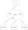
图2是MCU和CCU通信的网络架构图;Fig. 2 is the network architecture diagram of MCU and CCU communication;
图3是MCU和CCU之间的通信时序图;Fig. 3 is the communication sequence diagram between MCU and CCU;
图4是本发明中CCU缓存来自MCU的报文的流程图;Fig. 4 is the flow chart that CCU buffers the message from MCU in the present invention;
图5是本发明中CCU缓存发送给MCU的报文的流程图;Fig. 5 is the flow chart of the message that CCU buffers and sends to MCU in the present invention;
图6是本发明中DSC网络缓存日志排查的示意图;Fig. 6 is the schematic diagram of DSC network cache log checking in the present invention;
图7是MCU的软件结构示意图;Fig. 7 is the software structure schematic diagram of MCU;
图8是本发明中MCU应用层缓存日志过程的示意图;Fig. 8 is the schematic diagram of MCU application layer cache log process in the present invention;
图9是本发明中MCU系统接口层输出缓存区日志的示意图。FIG. 9 is a schematic diagram of the output buffer area log of the MCU system interface layer in the present invention.
具体实施方式Detailed ways
下面将结合附图对本发明作进一步说明。The present invention will be further described below with reference to the accompanying drawings.
在实际的地铁信号控制系统中,一条地铁线会分成多个区,每个区的轨旁设备,移动授权计算以及联锁防护由一台MCU控制,所有的区的MCU由一个CCU负责发送命令。因此单独看MCU和CCU的通信网络如图2所示。In the actual subway signal control system, a subway line will be divided into multiple zones. The trackside equipment, mobile authorization calculation and interlocking protection in each zone are controlled by one MCU, and one CCU is responsible for sending commands for all MCUs in the zone. . So look at the communication network of MCU and CCU separately as shown in Figure 2.
MCU和CCU之间通过交换机组成的DCS网络进行通信,一条地铁线只有一个CCU,对应多个MCU。在这样的架构下,当CCU上产生一条通信中断的报警时,可以很容易看到是与哪一个控区的MCU丢失通信,但是要进一步的分析通信丢失的原因还需要更多的信息。The MCU and the CCU communicate through the DCS network composed of switches. There is only one CCU in a subway line, which corresponds to multiple MCUs. Under such an architecture, when a communication interruption alarm is generated on the CCU, it is easy to see which MCU in the control area has lost communication, but more information is needed to further analyze the cause of communication loss.
MCU和CCU之间通过UDP(用户数据报协议)协议通信,MCU会作为通信开始的发起方,CCU会作为通信维护的应答方,它们之间的通信时序图如图3所示。在通信未建立时,MCU会首先向CCU发送通信建立请求帧,CCU收到通信请求后,判断通信可以建立,则会向MCU发送通信状态请求帧,MCU收到通信状态请求帧后,判断通信可以建立,并回复通信状态应答帧,至此一个完成的通信建立过程结束。后面CCU会定期发送心跳帧,也就是通信状态请求帧来维持通信,并监测当前的通信状态。The MCU and CCU communicate through the UDP (User Datagram Protocol) protocol. The MCU will be the initiator of the communication start, and the CCU will be the responder of the communication maintenance. The communication sequence diagram between them is shown in Figure 3. When the communication is not established, the MCU will first send the communication establishment request frame to the CCU. After receiving the communication request, the CCU judges that the communication can be established, and then sends the communication status request frame to the MCU. After the MCU receives the communication status request frame, it judges the communication status. It can be established and reply the communication status response frame, so far a completed communication establishment process ends. Later, the CCU will periodically send heartbeat frames, that is, communication status request frames, to maintain communication and monitor the current communication status.
在信号系统运营,过程中,经常会发生通信MCU和CCU通信中断的故障,导致此故障的原因一般分为下面三种:During the operation of the signal system, the communication interruption between the communication MCU and the CCU often occurs. The reasons for this failure are generally divided into the following three types:
1)CCU端没有接收到数据包或者没有发送相应的数据包。1) The CCU side did not receive the data packet or did not send the corresponding data packet.
2)DCS网络中交换机工作不稳定导致网络数据包的延迟或者丢失。2) The unstable operation of the switch in the DCS network leads to the delay or loss of network data packets.
3)MCU端没有收到数据包或者没有及时发送相应的数据包。3) The MCU end did not receive the data packet or did not send the corresponding data packet in time.
请参阅图1,本发明的CCU和MCU之间的通信错误诊断方法,包括下列步骤:Referring to Fig. 1, the communication error diagnosis method between the CCU and the MCU of the present invention includes the following steps:
步骤S1,诊断CCU造成的通信丢失:当CCU接收到来自MCU的数据,或者给MCU发送通信应答数据时,CCU通过日志缓存线程创建日志数据,并发送给第一日志服务器保存。然后通过检查第一日志服务器中的日志数据,诊断是否CCU造成的通信丢失。Step S1, diagnosing communication loss caused by the CCU: when the CCU receives data from the MCU or sends communication response data to the MCU, the CCU creates log data through a log cache thread, and sends the log data to the first log server for storage. Then, by checking the log data in the first log server, it is diagnosed whether the communication is lost due to the CCU.
为了监测CCU端是存在通信故障,我们可以在CCU的通信增加监测模块,将CCU端发送或者接收到的所有数据保存起来,这样在通信问题发生后可以迅速找出相关时间段的通信数据日志。在CCU端数据发送模块增加一个线程,在CCU每次准备向DCS网络发送数据包时,同时复制一份发送给第一日志服务器。在CCU端的数据接收模块增加一个线程,CCU接收到来自MCU的数据包时,也复制一份发送给第一日志服务器。具体如图4,每当CCU接收到来自MCU的数据时,CCU将创建一个线程:日志缓存线程,此线程会给MCU的数据报文加上缓存日志头,日志头包括两部分:MCU的ID和接收时间。当日志缓存线程创建日志数据完成后,立即把日志数据发送给第一日志服务器保存起来。实际应用中,第一日志服务器的硬盘空间应在1TB以上,这样日志数据的保存时间能达到1年以上。In order to monitor whether there is a communication failure on the CCU side, we can add a monitoring module to the CCU communication to save all the data sent or received by the CCU side, so that the communication data log of the relevant time period can be quickly found after a communication problem occurs. A thread is added to the data sending module on the CCU side, and each time the CCU prepares to send a data packet to the DCS network, a copy is sent to the first log server at the same time. A thread is added to the data receiving module on the CCU side. When the CCU receives a data packet from the MCU, it also copies a copy and sends it to the first log server. Specifically as shown in Figure 4, whenever the CCU receives data from the MCU, the CCU will create a thread: the log cache thread, this thread will add a cache log header to the MCU data packet, and the log header includes two parts: the MCU ID and reception time. After the log cache thread completes the creation of log data, the log data is immediately sent to the first log server for storage. In practical applications, the hard disk space of the first log server should be more than 1TB, so that log data can be stored for more than one year.
如图5所示,每当CCU准备给MCU的发送通信应答数据时,CCU将创建一个线程:日志缓存线程,此线程会给CCU的数据报文加上缓存日志头,日志头包括两部分:MCU的ID和发送时间。当日志缓存线程创建日志数据完成后,立即把日志数据发送给第一日志服务器保存起来。As shown in Figure 5, whenever the CCU prepares to send communication response data to the MCU, the CCU will create a thread: the log cache thread. This thread will add a cache log header to the CCU's data packets. The log header consists of two parts: MCU ID and sending time. After the log cache thread completes the creation of log data, the log data is immediately sent to the first log server for storage.
步骤S2,诊断DCS网络造成的通信丢失:由于DCS网络中的交换机数量众多,为了确定整体网络环境是否可靠,可以在DCS网络的出口和入口两处分别部署第二日志服务器,如图6所示。第二日志服务器通过网线与出口和入口的交换机网络映射口直连,这样当通信丢失故障发生后,可以通过对比两个第二日志服务器中的日志数据是否一致,诊断是否DCS网络造成的通信丢失。如果两者的数据不一致则说明,DCS的内部网络交换机出现了异常,需要进一步定位网络路径上的每一台交换机,这一部分工作可以继续使用部署第二日志服务器的方法慢慢排查,即:通过检查各第二日志服务器中日志数据来定位故障的交换机。Step S2, diagnosing the communication loss caused by the DCS network: due to the large number of switches in the DCS network, in order to determine whether the overall network environment is reliable, a second log server can be deployed at the egress and the ingress of the DCS network respectively, as shown in Figure 6 . The second log server is directly connected to the network mapping ports of the egress and the ingress switch through a network cable, so that when a communication loss failure occurs, you can compare whether the log data in the two second log servers are consistent to diagnose whether the communication is lost due to the DCS network. . If the data of the two are inconsistent, it means that the internal network switch of the DCS is abnormal, and it is necessary to further locate each switch on the network path. This part of the work can continue to be checked slowly by deploying the second log server, that is: by Check the log data in each second log server to locate the faulty switch.
步骤S3,诊断MCU造成的通信丢失:Step S3, diagnose the communication loss caused by the MCU:
在MCU应用层的接收端和发送端分别创建日志缓存区,当MCU应用层接收或发送数据时,生成日志数据并存入相应的日志缓存区。当MCU应用层判断发生通信丢失时,将各日志缓存区中的日志数据输出到系统日志中,并清空日志缓存区。通过检查系统日志中的日志数据,诊断是否MCU应用层造成的通信丢失。Log buffers are created respectively at the receiver and sender of the MCU application layer. When the MCU application layer receives or sends data, log data is generated and stored in the corresponding log buffer. When the MCU application layer determines that communication is lost, it outputs the log data in each log buffer to the system log, and clears the log buffer. Diagnose whether communication is lost due to the MCU application layer by checking the log data in the system log.
在MCU系统接口层的接收端和发送端分别创建日志缓存区,当MCU系统接口层接收或发送数据时,生成日志数据并存入相应的日志缓存区。当MCU应用层判断发生通信丢失时,MCU应用层调用MCU系统接口层的通信中断接口函数告知MCU系统接口层,MCU系统接口层将各日志缓存区中的日志数据输出到系统日志中,并清空日志缓存区。通过检查系统日志中的日志数据,诊断是否MCU系统接口层造成的通信丢失。Log buffers are created respectively at the receiver and sender of the MCU system interface layer. When the MCU system interface layer receives or sends data, log data is generated and stored in the corresponding log buffer. When the MCU application layer judges that communication is lost, the MCU application layer calls the communication interruption interface function of the MCU system interface layer to inform the MCU system interface layer, and the MCU system interface layer outputs the log data in each log buffer to the system log and clears it log buffer. By checking the log data in the system log, diagnose whether the communication is lost due to the interface layer of the MCU system.
具体地,MCU作为实时的安全系统,由于硬件性能的限制以及本身的响应时间的限制,MCU的执行周期为100ms,因此不能再使用全部缓存日志的办法保存所有和CCU的数据报文。那么考虑在MCU的应用层和系统平台层面增加通信缓存机制,来排查导致报文丢失的原因。如图7所示,MCU的软件结构示意图。MCU应用层通过系统接口层使用linux内核的服务,那么通信数据包需要在MCU应用层和系统接口层两个模块中进行定位。Specifically, the MCU is a real-time security system. Due to the limitation of hardware performance and its own response time, the execution period of the MCU is 100ms. Therefore, the method of buffering all logs can no longer be used to save all data messages with the CCU. Then consider adding a communication buffer mechanism at the application layer and system platform level of the MCU to check the cause of packet loss. As shown in Figure 7, a schematic diagram of the software structure of the MCU. The MCU application layer uses the services of the linux kernel through the system interface layer, so the communication data packets need to be located in the two modules of the MCU application layer and the system interface layer.
MCU应用层接收端的日志缓存过程如下:The log caching process at the receiving end of the MCU application layer is as follows:
MCU应用层的接收端接收到CCU的数据报文时,MCU将接收CCU发送的心跳查询帧,如果预设时间内没收到CCU的心跳查询帧,则MCU会判断通信丢失。那么考虑在MCU内部创建一个临时的日志缓存区,日志缓存区的大小可以根据实际的硬件限制决定,但一般建议使用通信中断周期两倍以上的数据包容量。例如:如果通信终端周期为T=3s,心跳查询帧的发送周期在Ts=500ms,最大的数据包容量C=200Byte,那么缓冲区的大小BufferCapacity=(T*2/Ts)*C=(3s*2/500ms)*200B=2.4KB。When the receiving end of the MCU application layer receives the data packet from the CCU, the MCU will receive the heartbeat query frame sent by the CCU. If the heartbeat query frame from the CCU is not received within the preset time, the MCU will determine that the communication is lost. Then consider creating a temporary log buffer area inside the MCU. The size of the log buffer area can be determined according to the actual hardware limit, but it is generally recommended to use a data packet capacity that is more than twice the communication interruption period. For example: if the communication terminal period is T=3s, the sending period of the heartbeat query frame is Ts=500ms, and the maximum data packet capacity is C=200Byte, then the buffer size BufferCapacity=(T*2/Ts)*C=(3s *2/500ms)*200B=2.4KB.
当MCU应用层收到CCU报文时,首先进行内部的数据有效性检查,检查内容如下:1)CRC校验码检查;2)应用层数据校验检查;3)消息类型检查;4)消息长度检查;5)时间戳检查;6)消息序列号检查。When the MCU application layer receives the CCU message, it first performs an internal data validity check. The check contents are as follows: 1) CRC check code check; 2) application layer data check check; 3) message type check; 4) message Length check; 5) Timestamp check; 6) Message sequence number check.
检查完成后将检查结果和消息到达时间以及消息内容组成一个整体报文保存到缓存队列之中。即:MCU应用层接收数据时,生成的日志数据指:CCU数据包加上日志头,该日志头包括:CCU数据包到达时间和CCU数据包校验结果。After the check is completed, the check result, the arrival time of the message, and the content of the message form a whole message and save it in the cache queue. That is, when the MCU application layer receives data, the generated log data refers to the CCU data packet plus the log header, and the log header includes: the arrival time of the CCU data packet and the verification result of the CCU data packet.
MCU在接收到CCU数据时,如图8所示将日志缓存到日志缓存区中。当MCU应用层判断发生通信丢失时,立即将缓存区中的数据输出到系统日志中,并清空日志缓存区。When the MCU receives the CCU data, it buffers the log in the log buffer as shown in Figure 8. When the MCU application layer judges that communication is lost, it immediately outputs the data in the buffer area to the system log, and clears the log buffer area.
MCU应用层发送端与MCU应用层接收端的日志缓存过程一致。只是MCU应用层发送数据时,生成的日志数据指:MCU数据包加上日志头,该日志头包括:MCU数据包发送时间和MCU的ID。The log buffering process of the sending end of the MCU application layer and that of the receiving end of the MCU application layer is consistent. It is only that when the MCU application layer sends data, the generated log data refers to: the MCU data packet plus the log header, and the log header includes: the sending time of the MCU data packet and the ID of the MCU.
MCU系统接口层的发送端和接收端的日志缓存过程,与MCU应用层接收端一致。MCU系统接口层和MCU应用层不同的地方在于:系统接口层并不知晓MCU与CCU的通信是否中断,因此MCU系统接口层缓存区的数据并不会在通信中断时自动保存到系统日志当中。为了解决这一问题,需要在MCU系统接口层加上通信中断接口函数,当MCU应用层判断通信中断时调用通信中断接口函数来告知MCU系统接口层,将MCU系统接口层缓存的通信数据输出到系统日志之中。如图9所示。MCU系统接口层接收数据时,生成的日志数据指:CCU数据包加上日志头,该日志头包括:CCU数据包到达时间和CCU数据包校验结果。MCU系统接口层发送数据时,生成的日志数据指:MCU数据包加上日志头,该日志头包括:MCU数据包发送时间和MCU的ID。The log buffering process of the sender and receiver of the MCU system interface layer is the same as that of the receiver of the MCU application layer. The difference between the MCU system interface layer and the MCU application layer is that the system interface layer does not know whether the communication between the MCU and the CCU is interrupted, so the data in the buffer area of the MCU system interface layer is not automatically saved to the system log when the communication is interrupted. In order to solve this problem, it is necessary to add a communication interrupt interface function to the MCU system interface layer. When the MCU application layer determines that the communication is interrupted, the communication interrupt interface function is called to inform the MCU system interface layer, and the communication data buffered by the MCU system interface layer is output to the in the system log. As shown in Figure 9. When the MCU system interface layer receives data, the generated log data refers to: the CCU data packet plus a log header, and the log header includes: the arrival time of the CCU data packet and the verification result of the CCU data packet. When the MCU system interface layer sends data, the generated log data refers to: the MCU data packet plus the log header, and the log header includes: the sending time of the MCU data packet and the ID of the MCU.
以上实施例仅供说明本发明之用,而非对本发明的限制,有关技术领域的技术人员,在不脱离本发明的精神和范围的情况下,还可以作出各种变换或变型,因此所有等同的技术方案也应该属于本发明的范畴,应由各权利要求所限定。The above embodiments are only for illustrating the present invention, rather than limiting the present invention. Those skilled in the relevant technical field can also make various changes or modifications without departing from the spirit and scope of the present invention. Therefore, all equivalents The technical solution of the invention should also belong to the scope of the present invention and should be defined by the claims.
Claims (7)
Translated fromChinesePriority Applications (1)
| Application Number | Priority Date | Filing Date | Title |
|---|---|---|---|
| CN201910531763.1ACN110191027B (en) | 2019-06-19 | 2019-06-19 | Communication error diagnosis method between CCU and MCU |
Applications Claiming Priority (1)
| Application Number | Priority Date | Filing Date | Title |
|---|---|---|---|
| CN201910531763.1ACN110191027B (en) | 2019-06-19 | 2019-06-19 | Communication error diagnosis method between CCU and MCU |
Publications (2)
| Publication Number | Publication Date |
|---|---|
| CN110191027A CN110191027A (en) | 2019-08-30 |
| CN110191027Btrue CN110191027B (en) | 2022-08-16 |
Family
ID=67722407
Family Applications (1)
| Application Number | Title | Priority Date | Filing Date |
|---|---|---|---|
| CN201910531763.1AActiveCN110191027B (en) | 2019-06-19 | 2019-06-19 | Communication error diagnosis method between CCU and MCU |
Country Status (1)
| Country | Link |
|---|---|
| CN (1) | CN110191027B (en) |
Families Citing this family (2)
| Publication number | Priority date | Publication date | Assignee | Title |
|---|---|---|---|---|
| EP4319045A1 (en)* | 2022-08-05 | 2024-02-07 | Volocopter GmbH | Method and system for verifying data communication integrity in an aircraft |
| CN116932272B (en)* | 2023-09-14 | 2023-11-21 | 飞腾信息技术有限公司 | Error reporting method and microprocessor |
Citations (2)
| Publication number | Priority date | Publication date | Assignee | Title |
|---|---|---|---|---|
| JP2000215185A (en)* | 1999-01-01 | 2000-08-04 | Seiko Epson Corp | Processor system |
| CN108760337A (en)* | 2018-05-31 | 2018-11-06 | 武汉理工大学 | A kind of motorcycle remote supervision system |
Family Cites Families (5)
| Publication number | Priority date | Publication date | Assignee | Title |
|---|---|---|---|---|
| US8036121B2 (en)* | 2006-08-22 | 2011-10-11 | Nec Corporation | Method of estimating quality degradation on network in communication network system |
| CN102904775B (en)* | 2012-09-29 | 2015-04-29 | 华为技术有限公司 | Method, apparatus and system for measuring network packet loss |
| CN109714221B (en)* | 2017-10-25 | 2022-11-01 | 阿里巴巴集团控股有限公司 | Method, device and system for determining network data packet |
| CN107968729B (en)* | 2017-12-22 | 2020-11-20 | 中国铁道科学研究院通信信号研究所 | A railway signal data stream storage management system |
| CN108960220B (en)* | 2018-10-31 | 2019-02-15 | 上海电气泰雷兹交通自动化系统有限公司 | Reliability Analysis Method of Signal System Communication Data Based on State Machine Model |
- 2019
- 2019-06-19CNCN201910531763.1Apatent/CN110191027B/enactiveActive
Patent Citations (2)
| Publication number | Priority date | Publication date | Assignee | Title |
|---|---|---|---|---|
| JP2000215185A (en)* | 1999-01-01 | 2000-08-04 | Seiko Epson Corp | Processor system |
| CN108760337A (en)* | 2018-05-31 | 2018-11-06 | 武汉理工大学 | A kind of motorcycle remote supervision system |
Also Published As
| Publication number | Publication date |
|---|---|
| CN110191027A (en) | 2019-08-30 |
Similar Documents
| Publication | Publication Date | Title |
|---|---|---|
| CN113890816B (en) | Network health state analysis method, device, computer equipment and storage medium | |
| US10708132B2 (en) | Technique for handling a status change in an interconnect node | |
| CN103957155B (en) | Message transmitting method, device and interconnecting interface | |
| EP3675398B1 (en) | Check code processing method, electronic device, and storage medium | |
| US11307945B2 (en) | Methods and apparatus for detecting, eliminating and/or mitigating split brain occurrences in high availability systems | |
| US8677183B2 (en) | Dynamic testing of networks | |
| US11184113B2 (en) | Packet replay in response to checksum error | |
| WO2020207479A1 (en) | Method and device for controlling network congestion | |
| CN108880917A (en) | Switching method and device of control surface equipment and switching control separation system | |
| CN106330588B (en) | BFD detection method and device | |
| US10541904B2 (en) | Establishing a network fault detection session | |
| CN110535940B (en) | BMC connection management method, system, equipment and storage medium | |
| CN110191027B (en) | Communication error diagnosis method between CCU and MCU | |
| US20250254121A1 (en) | Device management method, device, system, and storage medium | |
| WO2017215456A1 (en) | Alarming method, apparatus, network node and computer storage medium | |
| CN103024058A (en) | Method and system for invoking web services | |
| CN105897929B (en) | A method and device for backing up video surveillance data | |
| CN107332697B (en) | Fault detection method and device | |
| CN112804115B (en) | Method, device and equipment for detecting abnormity of virtual network function | |
| CN101159524B (en) | Automatic protection rearrangement checking method and device | |
| CN117201507A (en) | Cloud platform switching method and device, electronic equipment and storage medium | |
| US7899680B2 (en) | Storage of administrative data on a remote management device | |
| CN112511522B (en) | Method, device and equipment for reducing memory occupation in detection scanning | |
| CN108880882B (en) | A GSLB Processing Method Based on Health Check Improvement Mechanism | |
| KR100214134B1 (en) | Method for self-test of standby processor in full electronic switching system |
Legal Events
| Date | Code | Title | Description |
|---|---|---|---|
| PB01 | Publication | ||
| PB01 | Publication | ||
| SE01 | Entry into force of request for substantive examination | ||
| SE01 | Entry into force of request for substantive examination | ||
| GR01 | Patent grant | ||
| GR01 | Patent grant | ||
| CP03 | Change of name, title or address | Address after:201206 Shanghai City, Pudong New Area Jinhai Road No. 1000 Building No. 28 Patentee after:Shanghai Electric Group Transportation Automation System Co., Ltd. Country or region after:China Address before:201206 Shanghai City, Pudong New Area Jinhai Road No. 1000 Building No. 28 Patentee before:THALES SEC TRANSPORTATION SYSTEM Ltd. Country or region before:China | |
| CP03 | Change of name, title or address |