CN110187590B - Lens drives, camera modules and mobile phones - Google Patents
Lens drives, camera modules and mobile phonesDownload PDFInfo
- Publication number
- CN110187590B CN110187590BCN201910208862.6ACN201910208862ACN110187590BCN 110187590 BCN110187590 BCN 110187590BCN 201910208862 ACN201910208862 ACN 201910208862ACN 110187590 BCN110187590 BCN 110187590B
- Authority
- CN
- China
- Prior art keywords
- coil
- housing
- bobbin
- lens driving
- base
- Prior art date
- Legal status (The legal status is an assumption and is not a legal conclusion. Google has not performed a legal analysis and makes no representation as to the accuracy of the status listed.)
- Active
Links
Images


Classifications
- G—PHYSICS
- G02—OPTICS
- G02B—OPTICAL ELEMENTS, SYSTEMS OR APPARATUS
- G02B27/00—Optical systems or apparatus not provided for by any of the groups G02B1/00 - G02B26/00, G02B30/00
- G02B27/64—Imaging systems using optical elements for stabilisation of the lateral and angular position of the image
- G02B27/646—Imaging systems using optical elements for stabilisation of the lateral and angular position of the image compensating for small deviations, e.g. due to vibration or shake
- G—PHYSICS
- G02—OPTICS
- G02B—OPTICAL ELEMENTS, SYSTEMS OR APPARATUS
- G02B13/00—Optical objectives specially designed for the purposes specified below
- G02B13/001—Miniaturised objectives for electronic devices, e.g. portable telephones, webcams, PDAs, small digital cameras
- G—PHYSICS
- G02—OPTICS
- G02B—OPTICAL ELEMENTS, SYSTEMS OR APPARATUS
- G02B7/00—Mountings, adjusting means, or light-tight connections, for optical elements
- G02B7/02—Mountings, adjusting means, or light-tight connections, for optical elements for lenses
- G—PHYSICS
- G02—OPTICS
- G02B—OPTICAL ELEMENTS, SYSTEMS OR APPARATUS
- G02B7/00—Mountings, adjusting means, or light-tight connections, for optical elements
- G02B7/02—Mountings, adjusting means, or light-tight connections, for optical elements for lenses
- G02B7/04—Mountings, adjusting means, or light-tight connections, for optical elements for lenses with mechanism for focusing or varying magnification
- G02B7/09—Mountings, adjusting means, or light-tight connections, for optical elements for lenses with mechanism for focusing or varying magnification adapted for automatic focusing or varying magnification
- G—PHYSICS
- G03—PHOTOGRAPHY; CINEMATOGRAPHY; ANALOGOUS TECHNIQUES USING WAVES OTHER THAN OPTICAL WAVES; ELECTROGRAPHY; HOLOGRAPHY
- G03B—APPARATUS OR ARRANGEMENTS FOR TAKING PHOTOGRAPHS OR FOR PROJECTING OR VIEWING THEM; APPARATUS OR ARRANGEMENTS EMPLOYING ANALOGOUS TECHNIQUES USING WAVES OTHER THAN OPTICAL WAVES; ACCESSORIES THEREFOR
- G03B3/00—Focusing arrangements of general interest for cameras, projectors or printers
- G03B3/10—Power-operated focusing
- G—PHYSICS
- G03—PHOTOGRAPHY; CINEMATOGRAPHY; ANALOGOUS TECHNIQUES USING WAVES OTHER THAN OPTICAL WAVES; ELECTROGRAPHY; HOLOGRAPHY
- G03B—APPARATUS OR ARRANGEMENTS FOR TAKING PHOTOGRAPHS OR FOR PROJECTING OR VIEWING THEM; APPARATUS OR ARRANGEMENTS EMPLOYING ANALOGOUS TECHNIQUES USING WAVES OTHER THAN OPTICAL WAVES; ACCESSORIES THEREFOR
- G03B5/00—Adjustment of optical system relative to image or object surface other than for focusing
- H—ELECTRICITY
- H02—GENERATION; CONVERSION OR DISTRIBUTION OF ELECTRIC POWER
- H02K—DYNAMO-ELECTRIC MACHINES
- H02K41/00—Propulsion systems in which a rigid body is moved along a path due to dynamo-electric interaction between the body and a magnetic field travelling along the path
- H02K41/02—Linear motors; Sectional motors
- H02K41/035—DC motors; Unipolar motors
- H02K41/0352—Unipolar motors
- H02K41/0354—Lorentz force motors, e.g. voice coil motors
- H02K41/0356—Lorentz force motors, e.g. voice coil motors moving along a straight path
- G—PHYSICS
- G03—PHOTOGRAPHY; CINEMATOGRAPHY; ANALOGOUS TECHNIQUES USING WAVES OTHER THAN OPTICAL WAVES; ELECTROGRAPHY; HOLOGRAPHY
- G03B—APPARATUS OR ARRANGEMENTS FOR TAKING PHOTOGRAPHS OR FOR PROJECTING OR VIEWING THEM; APPARATUS OR ARRANGEMENTS EMPLOYING ANALOGOUS TECHNIQUES USING WAVES OTHER THAN OPTICAL WAVES; ACCESSORIES THEREFOR
- G03B2205/00—Adjustment of optical system relative to image or object surface other than for focusing
- G03B2205/0007—Movement of one or more optical elements for control of motion blur
- G03B2205/0015—Movement of one or more optical elements for control of motion blur by displacing one or more optical elements normal to the optical axis
- G—PHYSICS
- G03—PHOTOGRAPHY; CINEMATOGRAPHY; ANALOGOUS TECHNIQUES USING WAVES OTHER THAN OPTICAL WAVES; ELECTROGRAPHY; HOLOGRAPHY
- G03B—APPARATUS OR ARRANGEMENTS FOR TAKING PHOTOGRAPHS OR FOR PROJECTING OR VIEWING THEM; APPARATUS OR ARRANGEMENTS EMPLOYING ANALOGOUS TECHNIQUES USING WAVES OTHER THAN OPTICAL WAVES; ACCESSORIES THEREFOR
- G03B2205/00—Adjustment of optical system relative to image or object surface other than for focusing
- G03B2205/0053—Driving means for the movement of one or more optical element
- G03B2205/0069—Driving means for the movement of one or more optical element using electromagnetic actuators, e.g. voice coils
Landscapes
- Physics & Mathematics (AREA)
- General Physics & Mathematics (AREA)
- Optics & Photonics (AREA)
- Engineering & Computer Science (AREA)
- Chemical & Material Sciences (AREA)
- Combustion & Propulsion (AREA)
- Electromagnetism (AREA)
- Power Engineering (AREA)
- Lens Barrels (AREA)
- Adjustment Of Camera Lenses (AREA)
- Reciprocating, Oscillating Or Vibrating Motors (AREA)
Abstract
Translated fromChinese
Description
Translated fromChinese本申请是申请日为2014年5月29日、申请号为201410233894.9、发明名称为“镜头驱动装置”的专利申请的分案申请。This application is a divisional application of a patent application with an application date of May 29, 2014, an application number of 201410233894.9, and an invention name of "lens driving device".
技术领域technical field
本发明涉及镜头驱动装置,且更具体地涉及考虑到使用者的手抖修正功能和自动对焦功能而改进构造的镜头驱动装置、包括该镜头驱动装置的照相机模块、以及包括上述照相机模块的移动电话。The present invention relates to a lens driving device, and more particularly, to a lens driving device whose structure is improved in consideration of a user's hand-shake correction function and an autofocus function, a camera module including the lens driving device, and a mobile phone including the above-mentioned camera module .
背景技术Background technique
当手持拍照装置拍照时,不可避免地发生手抖现象。手抖现象引起这一拍照装置抖动。在手抖时拍摄的图像可能看起来模糊,并且当针对短距离的对象对焦时难以准确地对焦。When the camera device is hand-held to take pictures, a hand-shake phenomenon inevitably occurs. The hand-shake phenomenon causes the camera device to shake. Images captured with camera shake may look blurry and it may be difficult to focus accurately when focusing on subjects at short distances.
为了减少由于上述手抖现象而发生的振动,近来开发的拍照装置配备有光学图像稳定器(OIS),光学图像稳定器被构造为基本上减少使用者手持拍照装置拍摄图片时由于手抖现象而发生的振动。当使用照相机拍摄图片时,OIS模块就类似于帮助修正手抖的图像稳定模块那样。In order to reduce vibrations due to the above-mentioned hand-shake phenomenon, recently developed photographing devices are equipped with an optical image stabilizer (OIS), which is configured to substantially reduce the hand-shake phenomenon caused by the hand-shake phenomenon when a user holds the photographic device to take pictures. vibration that occurs. When taking pictures with a camera, the OIS module acts like an image stabilization module that helps correct for hand shake.
近年来,随着适配于智能手机、平板PC(个人计算机)等,公开了一种用于移动设备的照相机模块,移动设备通常配备有AF(自动对焦)功能和防手抖功能。In recent years, with adaptation to smartphones, tablet PCs (Personal Computers), and the like, a camera module for mobile devices, which are generally equipped with an AF (Auto Focus) function and an anti-hand shake function, has been disclosed.
OIS模块适合镜头移位方法,其中,镜头被构造为响应于沿X轴线、Y轴线移动的对象而进行水平移动。The OIS module is suitable for lens shift methods, where the lens is configured to move horizontally in response to an object moving along the X-axis, Y-axis.
然而,在上述镜头移位方法的情况下,就要借助AF模块,使在Z轴线上移动的镜头单元也在X轴线和Y轴线上移动,这样的操作要求AF模块中有一定空间以在X轴线、Y轴线上移动镜头单元。为此,照相机模块的宽度就会因其结构特性而增大,所以难以制造尺寸紧凑且更薄的拍照装置。However, in the case of the above-mentioned lens shift method, it is necessary to use the AF module to make the lens unit moving on the Z axis also move on the X axis and the Y axis. Move the lens unit on the axis and the Y axis. For this reason, the width of the camera module is increased due to its structural characteristics, so it is difficult to manufacture a compact and thinner photographing device.
由于AF模块的镜头被构造为基本上沿水平方向移动,所以光学系统的光轴可抖动。Since the lens of the AF module is configured to move substantially in the horizontal direction, the optical axis of the optical system may shake.
发明内容SUMMARY OF THE INVENTION
因此,本发明的目的是提供一种与现有技术相比,AF功能和OIS功能的响应更为快速并且操作更为可靠的照相机模块。Therefore, an object of the present invention is to provide a camera module with faster response of the AF function and OIS function and more reliable operation than the prior art.
本发明的另一目的是提供一种能够被很容易地组装的照相机模块。Another object of the present invention is to provide a camera module that can be easily assembled.
为实现上面的目的,本发明提供一种镜头驱动装置,其包括:盖盒,其上侧表面包括被形成为露出镜头的开口,其侧表面从该上侧表面延伸到基座;该基座被固定到该盖盒;壳体,被设置在该基座的顶部上,并沿与光轴垂直的第一方向和第二方向移动;线圈架,被容置在该壳体中,并沿光轴方向移动;致动器,包括被设置在该壳体中的磁体单元、被设置在该线圈架的外侧表面中的第一线圈单元和被设置在该基座的顶部上的第二线圈单元;以及衬底,被设置在该第二线圈单元与该基座之间,以控制该第一线圈单元与该第二线圈单元。To achieve the above object, the present invention provides a lens driving device comprising: a cover case whose upper side surface includes an opening formed to expose a lens, and whose side surface extends from the upper side surface to a base; the base is fixed to the cover case; a casing is provided on top of the base and moves along first and second directions perpendicular to the optical axis; a coil former is accommodated in the casing and moved along the optical axis direction movement; an actuator including a magnet unit provided in the housing, a first coil unit provided in the outer side surface of the bobbin, and a second coil provided on top of the base a unit; and a substrate disposed between the second coil unit and the base to control the first coil unit and the second coil unit.
另外,所述壳体包括至少两个从下侧表面突出的下止动部,而所述基座包括形状与所述盖盒的内侧表面匹配的基体、在该基体的中心处形成的中空部、以及从该基体的顶部突出并与该盖盒的内侧表面形成面接触的接合部,且该基座的接合部包括凹部,该凹部容置该下止动部并限制该壳体的向下运动及第一方向和第二方向运动。In addition, the case includes at least two lower stoppers protruding from the lower side surface, and the base includes a base body whose shape matches the inner side surface of the cover case, a hollow portion formed at the center of the base body , and an engaging portion protruding from the top of the base body and in surface contact with the inner side surface of the cover case, and the engaging portion of the base includes a recessed portion that accommodates the lower stop portion and restricts the downward movement of the housing Movement and movement in the first and second directions.
另外,所述线圈架包括至少两个被竖直地设置在该线圈架的外表面上的凸缘单元,且所述壳体包括在内侧表面中的安装部,所述凸缘单元被安装在该安装部中。In addition, the bobbin includes at least two flange units vertically disposed on an outer surface of the bobbin, and the housing includes a mounting portion in an inner side surface, the flange units being mounted on in the installation section.
另外,所述壳体包括至少两个从该壳体的上侧表面突出且位置靠近所述盖盒的上止动部。In addition, the case includes at least two upper stoppers protruding from the upper side surface of the case and located close to the cover case.
另外,所述上止动部被设置成靠近磁体单元。In addition, the upper stopper is provided close to the magnet unit.
另外,所述第一线圈单元被设置成面对所述磁体单元的内侧表面,且所述第二线圈单元被设置成面对该磁体单元的下侧表面。In addition, the first coil unit is provided to face the inner side surface of the magnet unit, and the second coil unit is provided to face the lower side surface of the magnet unit.
另外,所述第二线圈单元是图案化线圈或单独线圈。In addition, the second coil unit is a patterned coil or an individual coil.
另外,所述第二线圈单元和所述衬底通过焊接方法来联结,且所述基座的本体包括焊球容置凹槽,在该第二线圈单元与该衬底接合期间产生的焊球被容置于该焊球容置凹槽中。In addition, the second coil unit and the substrate are coupled by a soldering method, and the body of the base includes a solder ball accommodating groove, solder balls generated during the bonding of the second coil unit and the substrate is accommodated in the solder ball accommodating groove.
另外,还包括弹性单元,该弹性单元将通过所述衬底输入的电功率输送到所述第一线圈单元,并支撑所述壳体的第一或第二方向的运动。In addition, an elastic unit is also included, the elastic unit transmits the electric power input through the substrate to the first coil unit, and supports the movement of the casing in the first or second direction.
还提供:上部弹簧,其被设置在所述壳体的顶部上;下部弹簧,其被设置在所述壳体的下部;以及至少两个或至少四个侧部弹簧,其被设置在该壳体与所述基座之间。Also provided are: an upper spring provided on the top of the housing; a lower spring provided on the lower portion of the housing; and at least two or at least four side springs provided on the housing between the body and the base.
另外,所述侧部弹簧中的两个电连接至所述衬底和所述上部弹簧,且该上部弹簧包括电连接至缠绕在所述第一线圈单元上的线圈的一端的第一上部弹簧和电连接至缠绕在该第一线圈单元上的该线圈的另一端的第二上部弹簧。In addition, two of the side springs are electrically connected to the substrate and the upper spring, and the upper spring includes a first upper spring electrically connected to one end of a coil wound on the first coil unit and a second upper spring electrically connected to the other end of the coil wound on the first coil unit.
还设置了霍尔传感器单元,其被安装在所述衬底上,用以检测所述致动器的运动。A hall sensor unit is also provided, which is mounted on the substrate to detect movement of the actuator.
另外,所述基座包括霍尔传感器容置凹槽,该霍尔传感器容置凹槽被形成为容置所述霍尔传感器单元。In addition, the base includes a hall sensor accommodating groove formed to accommodate the hall sensor unit.
另外,磁体单元包括四个磁体,这四个磁体按90°角度的规则间隔来设置,所述霍尔传感器单元包括两个霍尔传感器,这两个霍尔传感器与所述磁体单元一起相对于光轴被设置成直线并被设置成面对相邻的磁体。In addition, the magnet unit includes four magnets arranged at regular intervals of 90° angle, and the Hall sensor unit includes two Hall sensors, which are opposite to the magnet unit together with the magnet unit. The optical axis is arranged in a straight line and is arranged to face adjacent magnets.
另外,所述磁体单元被设置在所述壳体的拐角中,并包括面对所述第一线圈单元的第一磁体和面对所述第二线圈单元的第二磁体。In addition, the magnet unit is disposed in a corner of the housing, and includes a first magnet facing the first coil unit and a second magnet facing the second coil unit.
另外,所述上部弹簧、所述下部弹簧、或所述侧部弹簧是板簧。In addition, the upper spring, the lower spring, or the side spring may be a leaf spring.
另外,所述侧部弹簧包括:第一接合部,接合到所述壳体的侧表面;第二接合部,接合到所述基座的侧表面;以及弹性部,连接该第一接合部和该第二接合部,并且包括至少一个弯曲部。In addition, the side spring includes: a first engagement portion engaged to the side surface of the housing; a second engagement portion engaged to the side surface of the base; and an elastic portion connecting the first engagement portion and the The second engagement portion includes at least one curved portion.
另外,所述弹性部包括两个弯曲部,这两个弯曲部在所述第一接合部与第二接合部之间彼此面对。In addition, the elastic portion includes two curved portions facing each other between the first engaging portion and the second engaging portion.
另外,在所述壳体的外表面中形成有用于固定所述第一接合部的侧表面接合突出部,而在该第一接合部中形成有接合到该侧表面突出部的侧表面接合孔或凹槽,并且所述基座的每侧形成有侧部弹簧插入凹槽,所述第二接合部被插入或设置在该侧部弹簧插入凹槽中。In addition, a side surface engaging protrusion for fixing the first engaging portion is formed in the outer surface of the housing, and a side surface engaging hole to which the side surface protrusion is engaged is formed in the first engaging portion or groove, and each side of the base is formed with a side spring insertion groove into which the second engaging portion is inserted or disposed.
<条件表达式><conditional expression>
Kx=0.5~2.0KyKx =0.5~2.0Ky
Kz=5~100KxKz =5~100Kx
其中,K代表弹簧常数,Kz代表弹簧常数沿光轴方向的分量,Kx和Ky代表弹簧常数沿第一方向和第二方向的分量。Wherein, K represents the spring constant, Kz represents the component of the spring constant along the optical axis direction, and Kx andKy represent the components of the spring constant along the first direction and the second direction.
有益效果beneficial effect
在本发明的优选实施例中,提供一种照相机模块,该照相机模块的操作快速响应且操作可靠,按照通过镜头单元来获得自动对焦功能,并通过壳体构造来获得防手抖功能的方式,能够实现该照相机模块的快速而可靠的操作。In a preferred embodiment of the present invention, there is provided a camera module, the operation of which is fast-response and reliable in operation, according to the method of obtaining the auto-focus function through the lens unit, and obtaining the anti-shake function through the housing structure, Fast and reliable operation of the camera module can be achieved.
根据本发明的优选实施例的照相机模块包括侧部弹簧,该侧部弹簧具有良好的抗冲击性和可靠的防手抖功能。The camera module according to the preferred embodiment of the present invention includes a side spring having good shock resistance and reliable anti-shake function.
在本发明的优选实施例中,因为所述第二线圈单元与所述磁体单元被设置成直线,所以借助引力能够很容易地组装产品。In a preferred embodiment of the present invention, since the second coil unit and the magnet unit are arranged in a straight line, the product can be easily assembled by means of attractive force.
附图说明Description of drawings
本发明进一步的目的和优点能够通过以下结合附图的详细描述更完整地理解,附图中:Further objects and advantages of the present invention can be more fully understood from the following detailed description in conjunction with the accompanying drawings, in which:
图1是示出根据本发明的优选实施例的照相机模块的立体图;FIG. 1 is a perspective view illustrating a camera module according to a preferred embodiment of the present invention;
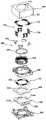
图2是示出根据本发明的优选实施例的照相机模块的立体分解图;2 is an exploded perspective view illustrating a camera module according to a preferred embodiment of the present invention;
图3是示出根据本发明的优选实施例的线圈架的立体图;3 is a perspective view showing a coil former according to a preferred embodiment of the present invention;
图4是示出根据本发明的优选实施例的壳体的立体图;4 is a perspective view showing a case according to a preferred embodiment of the present invention;
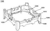
图5是示出根据本发明的优选实施例的基座的立体图;5 is a perspective view showing a base according to a preferred embodiment of the present invention;
图6是示出根据本发明的优选实施例的致动器的示意图;6 is a schematic diagram illustrating an actuator according to a preferred embodiment of the present invention;
图7是示出根据本发明的优选实施例的弹性单元的视图;7 is a view showing an elastic unit according to a preferred embodiment of the present invention;
图8是示出侧部弹簧的略微变形的立体图,这个视图是为了更好理解本发明的优选实施例而示出的;Figure 8 is a perspective view showing a slight deformation of the side spring, this view is shown for better understanding of the preferred embodiment of the present invention;
图9是沿根据本发明的优选实施例的照相机模块的对角线方向截取的侧剖视图;9 is a side cross-sectional view taken along a diagonal direction of a camera module according to a preferred embodiment of the present invention;
图10是示出根据本发明的另一实施例的照相机模块的立体分解图;10 is an exploded perspective view illustrating a camera module according to another embodiment of the present invention;
图11是示出图10的壳体的立体图;Fig. 11 is a perspective view showing the housing of Fig. 10;
图12是示出图10的侧部弹簧的视图;Figure 12 is a view showing the side spring of Figure 10;
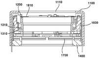
图13是沿图1的照相机的方向“A”截取的侧剖视图;Figure 13 is a side cross-sectional view taken along direction "A" of the camera of Figure 1;
图14是沿图1的照相机模块的方向“B”截取的侧剖视图;Figure 14 is a side cross-sectional view taken along direction "B" of the camera module of Figure 1;
图15是示出根据本发明的另一实施例的第一致动器和第二致动器的示意图;15 is a schematic diagram illustrating a first actuator and a second actuator according to another embodiment of the present invention;
图16是示出根据本发明的另一实施例的第一致动器和第二致动器的磁性方向的视图;16 is a view showing magnetic directions of a first actuator and a second actuator according to another embodiment of the present invention;
图17是示出侧部弹簧的略微变形的立体图,这个视图是为了更好理解本发明的另一实施例而示出的;以及Figure 17 is a perspective view showing a slight deformation of the side spring, this view is shown for a better understanding of another embodiment of the present invention; and
图18是示出根据本发明的另一实施例的侧部弹簧的示意图。18 is a schematic diagram illustrating a side spring according to another embodiment of the present invention.
具体实施方式Detailed ways
除非另外定义,本文使用的术语表示的意思与本领域中普通技术人员所使用的术语相同,如果本文使用的术语与通用术语冲突,则其解释遵循本发明的定义。Unless otherwise defined, terms used herein have the same meanings as those used by those of ordinary skill in the art, and if a term used herein conflicts with a generic term, the interpretation follows the definition of the present invention.
本文描述的发明只是为了描述具体实施例的目的,而并非旨在限制本发明。应注意,本说明书中相同的附图标记表示相同的部件。The invention described herein is for the purpose of describing specific embodiments only, and is not intended to limit the invention. It should be noted that the same reference numerals in this specification denote the same components.
图1是示出根据本发明的优选实施例的镜头驱动电机的立体图。FIG. 1 is a perspective view illustrating a lens driving motor according to a preferred embodiment of the present invention.
如图1所示,Z轴线代表光轴方向,X轴线代表与Z轴线方向垂直的第一方向,Y轴线代表与Z轴线和X轴线均垂直的第二方向。As shown in FIG. 1 , the Z axis represents the optical axis direction, the X axis represents a first direction perpendicular to the Z axis direction, and the Y axis represents a second direction perpendicular to both the Z axis and the X axis.
以下描述的优选实施例和另一实施例针对一种照相机模块,该照相机模块的自动对焦(AF)功能和防手抖功能可快速响应,并且这些功能的操作更为可靠,而且增强了照相机模块的耐久性和组装性。以下将参照附图描述本发明的多个技术特征。The preferred embodiment and another embodiment described below are directed to a camera module whose auto-focus (AF) function and anti-shake function can respond quickly, and the operation of these functions is more reliable, and the camera module is enhanced durability and assembly. Various technical features of the present invention will be described below with reference to the accompanying drawings.
图2是示出根据本发明的优选实施例的照相机模块的立体分解图。图3是示出根据本发明的优选实施例的线圈架的立体图。图4是示出根据本发明的优选实施例的壳体的立体图。图5是示出根据本发明的优选实施例的基座的立体图。图6是示出根据本发明的优选实施例的致动器的示意图。图7是示出根据本发明的优选实施例的弹性单元的示意图。图8是示出侧部弹簧的略微变形的立体图,这个视图是为了更好理解本发明的优选实施例而示出的。2 is an exploded perspective view illustrating a camera module according to a preferred embodiment of the present invention. 3 is a perspective view illustrating a bobbin according to a preferred embodiment of the present invention. 4 is a perspective view illustrating a case according to a preferred embodiment of the present invention. 5 is a perspective view illustrating a base according to a preferred embodiment of the present invention. 6 is a schematic diagram illustrating an actuator according to a preferred embodiment of the present invention. FIG. 7 is a schematic diagram illustrating an elastic unit according to a preferred embodiment of the present invention. Figure 8 is a perspective view showing a slight deformation of the side spring, this view is shown for better understanding of the preferred embodiment of the present invention.
图9是沿根据本发明的优选实施例的照相机模块的对角线方向截取的侧剖视图。9 is a side cross-sectional view taken along a diagonal direction of a camera module according to a preferred embodiment of the present invention.
如图1所示,根据本发明的实施例的镜头驱动电机的主要部件包括盖盒100、线圈架200、壳体300、基座400和致动器500。该镜头驱动电机还可包括衬底600和/或弹性单元700。As shown in FIG. 1 , the main components of the lens driving motor according to the embodiment of the present invention include a
如图1和图2所示,盖盒100被构造为容置线圈架200、壳体300、基座400和弹性单元700,并且被安装在基座400上,其构造与照相机模块或镜头驱动电机的外部轮廓相符。As shown in FIGS. 1 and 2 , the
如图中所示,盖盒100的顶部形成露出镜头的开口110。盖盒100可形成底部敞开的长方体形状,但是它也可形成各种形状。更具体地,当从上面观察时,盖盒100可形成四边形形状或八边形形状,而且盖盒的形状不限于此。As shown in the figure, the top of the
由于盖盒100的内表面与基座400的侧表面部或上表面紧密接触,所以盖盒100的下侧表面能够被基座400闭合,由此保护内部部件免受外部的冲击并防止杂质进入。因为基座400与盖盒100之间接合的缘故,所以盖盒100的侧表面,更具体地说在一侧表面中或侧下部中,可设有至少一个接合孔120。基座400的侧表面中设有接合突出部421,接合突出部421插入接合孔120中,因此照相机模块或镜头驱动电机能够具有可靠的密封功能和接合功能。Since the inner surface of the
盖盒100可具有保护照相机模块的部件或镜头驱动电机不受到移动电话等外部无线电干扰的功能。盖盒100可优选地由金属材料制成,或可由其它材料、例如模制材料或使用金属材料的插入模制材料制成。The
如图2和图3所示,线圈架200被容置在壳体300(将稍后描述)中。线圈架200可包括镜筒(图中未示),利用镜筒拍摄对象的图片。线圈架被容置在壳体300中,并固定到镜筒(图中未示),镜筒将被组装到照相机模块。线圈架200能够借助致动器500,相对于壳体300沿Z轴线方向移动。As shown in FIGS. 2 and 3 , the
镜筒(图中未示)可形成为圆筒外壳的形式,被构造为固定至少一个镜头。在镜筒的外圆周表面上可形成螺纹,该螺纹与形成于线圈架200的内表面中的螺纹201匹配以形成螺接。镜筒可不使用螺纹来接合,更具体地说,可使用粘合剂或类似方式来接合。镜筒可属于照相机模块的必要部件。A lens barrel (not shown) may be formed in the form of a cylindrical housing configured to hold at least one lens. Threads may be formed on the outer circumferential surface of the lens barrel, which mate with threads 201 formed in the inner surface of the
线圈架200的外圆周表面中可设有至少两个突出凸缘单元210。凸缘单元210被安装在壳体300的安装单元310上或被设置在安装单元310中,凸缘单元210的构造可用于限制线圈架200的向下运动和/或旋转运动。线圈架200的外表面中设有固定肋220;固定肋220突出,以设置第一线圈单元520。固定肋220可形成于线圈架200的外表面中,且处在凸缘单元210的下侧表面中。第一线圈单元可直接缠绕在线圈架的外表面上,或之前缠绕的线圈可被设置在线圈架的外侧或可被固定。At least two protruding
至少两个接合突出部从线圈架200的上表面突出,这些接合突出部与内接合孔712a或接合凹槽匹配,内接合孔712a或接合凹槽形成于上部弹簧710的内侧部712中。至少两个位置靠近盖盒100的辅助止动部240可突出。上表面的接合突出部230和内接合孔712a在插入之后,通过热固、粘附或钎焊方式固定。另外,辅助止动部的数量可被设置成四个、或六个、或八个,或被设置成偶数个或奇数个。At least two engaging protrusions protrude from the upper surface of the
如图2和图4所示,壳体300被安装在基座400上并支撑线圈架200。As shown in FIGS. 2 and 4 , the
壳体300由侧部弹簧(将稍后描述)支撑。壳体300可被安装在基座400(参考图9)之上。The
更明确地,壳体300被构造为与基座400的形状匹配的预定形状。在本发明的优选实施例中,基座400和壳体200被形成为四边形形状。但基座400和壳体200的形状不限于此。More specifically, the
在壳体300的外表面中,侧表面接合突出部333从每个侧表面突出,以接合侧部弹簧730的第一接合部731。在侧部弹簧730的第一接合部731中形成有第一接合孔731a或接合凹槽,第一接合孔731a或接合凹槽与侧表面接合突出部333匹配。侧表面接合突出部333和上表面第一接合孔731a或接合凹槽在插入之后,通过热固、粘附或钎焊的方式来固定。In the outer surface of the
在壳体300的上表面中,上侧接合突出部331从每个上表面突出,以接合上部弹簧710的外侧部。在上部弹簧710的外侧部711中可形成有上表面接合凹槽711a或接合凹槽,上表面接合凹槽711a或接合凹槽与上侧接合突出部331匹配。上侧接合突出部331与上表面接合孔711a或接合凹槽在插入之后,可通过热固、粘附或钎焊的方式来固定。In the upper surfaces of the
在壳体300中,至少两个上止动部330可从上表面突出,并且位置靠近盖盒100的顶部的内表面。可包括有至少两个下止动部320,下止动部320从下表面突出,并且当通电时漂浮在基座400的凹部422中,或被设置在该基座的凹部中。In the
上止动部330和下止动部320被设置在关于Z轴线的直线上,由此增强关于冲击的耐久性,并且被设置成靠近磁体单元510(将稍后描述),由此防止磁体单元510的重量引起的弯曲应力导致壳体300产生任何变形,但壳体300的构造并不局限于此。The
安装部310形成在壳体300的内侧。线圈架200的凸缘单元210被安装在安装单元310上或被设置在安装单元310中,所以能够限制线圈架200的向下运动或旋转。安装部310可从壳体300的内表面连续地突出,以形成边沿形状或槽形,或如图所示,安装部310可按规则的间隔形成。The mounting
如图2和图5所示,基座400形成与盖盒100的下部中的开口匹配的预定形状。在本发明的优选实施例中,基座400形成为四边形形状,但基座400的形状并不局限于此。基座400被固定到盖盒100的底部,并被构造为从下面支撑被容置在盖盒100中的部件。As shown in FIGS. 2 and 5 , the
基座400包括:基体410,形成与盖盒100的内表面匹配的预定形状;中空部410a,形成于基体410的中心处;以及接合部420,从基体410的顶部突出,并与盖盒100的内表面接触。这里也可不设置接合部。The
为了与盖盒100可靠接合,基体410的侧表面或接合部420中可形成有接合突出部421,接合突出部421与盖盒100中形成的接合凹槽120匹配。反之,接合突出部(图中未示)也可形成在盖盒100的侧表面内,而接合孔(图中未示)或接合凹槽可形成在基座400中。For reliable engagement with the
在基体410的每一侧可形成有侧部弹簧插入凹槽411,侧部弹簧730的第二接合部732被插入或设置在侧部弹簧插入凹槽411中。第二接合部可被插入或设置在裂缝形的凹槽中。A side
基体410的上表面中可形成有焊球容置凹槽413或/和霍尔传感器容置凹槽412,焊球容置凹槽413被构造为容置在焊接(钎焊)过程中产生的焊球(图中未示),霍尔传感器容置凹槽412被构造为容置霍尔传感器单元(稍后描述),因此照相机模块或镜头驱动电机的整个体积能够尺寸紧凑。A solder
焊球容置凹槽413在基体410的上表面按规则间隔形成。霍尔传感器容置凹槽412可关于磁体单元和X轴线方向在直线上形成(参考图9)。由于霍尔传感器容置凹槽412被构造为检测磁体沿第一方向(X轴线方向)和/或第二方向(Y轴线方向)的运动位移,所以可设置两个或更多个霍尔传感器容置凹槽412。这些霍尔传感器容置凹槽可被彼此接近地设置在靠近基座的侧部。Solder
接合部420的顶部或基体中可设置有凹部422;凹部422容置壳体300的下止动部320,并限制壳体300的向下运动和X轴线和Y轴线的旋转。此凹部可被设置在基座的拐角或侧部。A
这里,在接合部420中,凹部422可被形成为半圆形或各种凹槽形。凹部422的底部能够限制与下止动部420一起向下运动,而侧表面能够限制壳体的旋转运动(X轴线和Y轴线)。Here, in the
如图2和图6所示,根据本发明的致动器500配备有两个线圈单元520、520,这两个线圈单元被设置在磁体单元510中,以此获得防手抖功能和自动对焦功能。更明确地,线圈单元520提供自动对焦功能,而线圈单元530提供防手抖功能。As shown in FIG. 2 and FIG. 6 , the
根据本发明的实施例的壳体300位于基座400之上,并能够沿X轴线和Y轴线移动;线圈架200被容置在壳体300中,并能够沿Z轴线即光轴的方向移动。The
为了壳体300和/或线圈架200的运动,致动器500包括:磁体单元510,被设置在壳体300中或被设置在壳体的内侧表面中;第一线圈单元520,被设置在线圈架200中以沿Z轴线方向移动线圈架200,或被设置在线圈架的外侧表面中;以及第二线圈单元530,被设置在基座400的上表面中,用以沿X轴线和Y轴线方向移动壳体300,线圈架200被容置在壳体300中。For the movement of the
这里,第一线圈单元520被设置成面对磁体单元510的内表面,而第二线圈单元530被设置成面对磁体单元510的下表面。Here, the
更明确地,第一线圈单元520可预先以匹配线圈架200的外圆周表面的预定形状缠绕。在此情况下,固定肋220可被去除。另外,第一线圈单元可被缠绕在形成于线圈架200的外侧表面中的固定肋220上,所以第一线圈单元能够被设置在线圈架200的外圆周表面中并可电连接至衬底600(将稍后描述),所以能够以电子方式控制第一线圈单元。More specifically, the
缠绕在第一线圈单元520上的线圈利用电流来产生电磁场,而且所产生的电磁场与磁体单元510的电磁场相互作用,因此沿Z轴线方向(上下方向)即光轴方向移动线圈架200。这里,线圈架200的上下运动能够由上部弹簧710和下部弹簧720来支撑或限制。The coil wound on the
施加至第一线圈单元520的电力被供应到衬底600,一对或两个侧部弹簧730电连接至衬底600,一对或两个上部弹簧710电连接至所述一对或两个侧部弹簧730。电连接关系将稍后具体描述。所述一对或两个侧部弹簧可被设置成相互面对或被设置成可彼此接近。电力可按电流或电压的形式提供。The power applied to the
第二线圈单元530被设置在基座400的上表面上,以便沿X轴线和Y轴线方向移动壳体300。The
更详细地,第二线圈单元530可被安装在衬底600上,或可被设置在衬底600上,并可电连接至衬底600。与圆形的第一线圈单元520不同,在衬底600上可设置四个第一线圈单元520,这四个第一线圈单元相互之间的角度为90°。取决于设计规格,四个第二线圈单元530中的每一个可被单独地设置在衬底600上,或可被设置为两对、或可被分组,且由此使这些第二线圈单元可受控。In more detail, the
第二线圈单元530与磁体单元510位于沿Z轴线方向的直线上,以便沿X轴线和Y轴线方向移动壳体300。The
经由衬底600提供的电流被施加至缠绕在第二线圈单元530上的线圈,由此产生电磁场,所产生的电磁场与磁体单元510的电磁场相互作用,由此沿X轴线和Y轴线方向移动壳体300。The current supplied via the
磁体单元被设置在壳体的拐角中,并包括面对第一线圈单元的第一磁体以及面对第二线圈单元的第二磁体。这里,第一磁体和第二磁体可以是一体的。如果磁体单元被设置在壳体的拐角中,则磁体单元可形成为角部支柱的形状或三角形形状、梯形支柱形状、多角形支柱形状、或在有角支柱形状的部分处具有倒角的支柱形状。磁体单元的每个拐角就工艺来说可具有“R”值,或可基于设计而弯曲。The magnet unit is disposed in a corner of the housing, and includes a first magnet facing the first coil unit and a second magnet facing the second coil unit. Here, the first magnet and the second magnet may be integrated. If the magnet unit is disposed in the corner of the housing, the magnet unit may be formed in the shape of a corner pillar or a triangular shape, a trapezoidal pillar shape, a polygonal pillar shape, or a pillar with chamfers at a portion of the corner pillar shape shape. Each corner of the magnet unit may have an "R" value in terms of process, or may be curved based on design.
磁体单元可被设置在壳体的侧部。在此情况下,磁体单元具有四边形支柱形状,每个拐角就工艺来说可具有“R”值,或可基于设计而弯曲。The magnet unit may be provided on the side of the housing. In this case, the magnet unit has a quadrilateral pillar shape, and each corner may have an "R" value in terms of process, or may be curved based on design.
若考虑照相机模块的紧凑性,更明确地,若需要降低Z轴线方向即光轴方向的高度,第二线圈单元530可包括图案化线圈或单独的线圈。Considering the compactness of the camera module, more specifically, if the height in the Z-axis direction, that is, the optical axis direction needs to be reduced, the
在此情况下,第二线圈单元530的底表面被焊在衬底60的侧表面或上表面上,或使用Ag环氧树脂或导电环氧树脂电连接并安装在衬底600上。由于在钎焊过程中形成的焊球(图中未示)或AG环氧树脂或导电环氧树脂确定沿照相机模块的Z轴线方向的高度,所以在本发明的基座400中可形成有钎焊容置凹槽413,钎焊容置凹槽413容置焊球或AG环氧树脂或导电环氧树脂。In this case, the bottom surface of the
如图1和图2所示,衬底600接合至基座400、或被设置在基座400中、或固定到基座400,并被安装在基座400上,以便控制致动器500。As shown in FIGS. 1 and 2 , the
为了供电以控制第一线圈单元520和第二线圈单元530,衬底600可被设置在第二线圈单元530与基座400之间,并且例如可以是柔性印制电路板(FPCB)。In order to supply power to control the
衬底600可包括两个焊点610a和610b,这两个焊点被形成为电连接至两个侧部弹簧730a和730b的第二接合部732。两个第二接合部732中的每个可包括钎焊部732a,在钎焊部732a进行对衬底600的焊点610a、610b的钎焊。The
由于衬底600电连接至单独的印制电路板,所以上述衬底600可包括端子部620,用以获得电力,端子部620从至少一侧沿向下方向弯曲。上述印制电路板例如可以是属于照相机模块的印制电路板(将稍后描述)。衬底在两个侧表面处弯曲,并可被设置在基座中或固定到基座。可设置有多个端子,或可设置有至少两个、或可设置有四个或八个、或设置有多于十四个端子。Since the
如图2和图7所示,电气单元700包括上部弹簧710、下部弹簧720和侧部弹簧730。As shown in FIGS. 2 and 7 , the
上部弹簧710、下部弹簧720和侧部弹簧730可被设置在壳体300的每个表面中,或可由通用的盘簧制成,或为了提高生产效率,可由板簧制成(其中,单个板片被弯曲并切割)。The
上部弹簧710被接合进而被固定到壳体300的顶部和线圈架200的顶部,由此支撑线圈架200。上部弹簧710可被设置在壳体300的顶部,以便在线圈架200向上或向下移动时提供返回力。The
更明确地,上部弹簧710包括:电力输入构件710a(第一上部弹簧),来自印制电路板600的电力被输入至电力输入构件710a;以及电力输出构件710b(第二上部弹簧),所提供的电力由电力输出构件710b输出并输送到第一线圈单元520。More specifically, the
第一上部弹簧710a和第二上部弹簧710b可由板簧制成并相对于光轴对称,而且可由单个板簧制成。第一上部弹簧710a和第二上部弹簧710b可由两个被部分切割并且电绝缘的弹簧制成。优选地,出于输入和输出电力的缘故,第一上部弹簧710a和第二上部弹簧710b由单独的板簧制成。The first
第一上部弹簧710a和第二上部弹簧710b各自包括第一支撑部711(外侧部)、第二支撑部712(内侧部)以及上侧弹性部713(连接部),第二支撑部712固定到线圈架200,上侧弹性部713使外侧部711与内侧部712电连接。The first
如附图所示,连接部713可以是两个被设置在外侧部711与内侧部712之间的弯曲部,其构造并不局限于此。可设置一个或多个连接部。每个弹簧的弯曲部可被设置成多个,或多个弯曲部可被对称地设置。As shown in the drawings, the connecting
如前所述,至少一个上侧接合突出部331被设置在壳体300的上表面上。在外侧部711中,可形成有外侧接合凹槽711a、或形成有与上侧接合突出部331匹配的凹槽。也可不形成外侧接合凹槽711a或凹槽。As previously described, at least one upper engaging
外侧部711中可形成有第一突出部711b,第一突出部711b相应地电连接至两个侧部弹簧730,或者也可不形成这种突出部。第一突出部711b电连接至侧部弹簧730。这里,第一突出部711b可与侧部弹簧730整体弯曲,或可通过钎焊或铅焊、或Ag环氧树脂或导电环氧树脂来进行电连接。The
线圈架200的上表面中形成有至少一个上表面接合突出部230,而且内侧部712中可形成有内侧接合孔712a或与上表面接合突出部230匹配的凹槽。At least one upper
第一侧部弹簧710a和第二上部弹簧710b的每个内侧部712中可形成有第二突出部712b,第二突出部712b电连接至缠绕在第一线圈单元520上的线圈的一端520a和另一端520b,或者也可不形成第二突出部这样的部件。A
这里,第一突出部711b和侧部弹簧730、第二突出部712b、以及第二突出部712b的线圈的一端520a和另一端520b可通过钎焊或铅焊或Ag环氧树脂或导电环氧树脂电连接。Here, the
下部弹簧720被设置在壳体300的下端,以便支撑线圈架200的底部。衬底600的电力可不输入或输出,衬底600可由单个板簧制成。这里,下部弹簧720包括:外侧部721,被设置在壳体300中;内侧部722,被设置在线圈架200中;以及连接部,连接外侧部721和内侧部722。下部弹簧720的外侧部721和内侧部722可包括至少两个下部接合孔720a、720b或凹槽,至少两个下部接合孔720a、720b或凹槽接合到形成于壳体300或线圈架200的下表面中的突出部(图中未示)。A
为了使X轴线和Y轴线的振动衰减,侧部弹簧730接合或固定到壳体的表面、或壳体300的侧表面的一部分或侧表面上的部件。侧部弹簧的另一端或一部分接合到基座400的侧表面。侧部弹簧730可包括四个侧部弹簧,这四个侧部弹簧按90°角度的规则间隔来设置。In order to dampen the vibration of the X-axis and Y-axis, the side springs 730 are engaged or fixed to the surface of the housing, or a part of the side surface of the
更明确地,侧部弹簧730包括:第一接合部731,接合到壳体300的侧表面;第二接合部732,接合到基座400的侧表面;以及弹性部733,连接第一接合部731或第二接合部732,或相对于第一接合部731和第二接合部竖直地形成。More specifically, the
这里,弹性部733可以是至少一个弯曲部。弹性部733可被设置成相对于一个侧部弹簧730相互面对的两个弹性部,或可被设置成位于中心处或预定位置的一个弹性部。Here, the
侧部弹簧730的第一接合部731中形成有第一接合孔731a或凹槽,第一接合孔731a或凹槽与形成于壳体300中的侧表面接合突出部333匹配。这里,接合突出部333和第一接合孔731a或凹槽可通过热固、粘附或钎焊或焊接方式来固定。The first
通过相同的方式,第二接合部732以与第一接合部731相同的方式接合或固定到基座40。基座400中可形成有侧部弹簧插入凹槽11,侧部弹簧插入凹槽11与第二接合部732的宽度相同或匹配;或基座400中可形成有裂缝形凹槽,因此第二接合部732可在裂缝形凹槽中滑动接合或插入裂缝形凹槽中;或第二接合部可被设置在这样的插入凹槽中,或可接合或固定到裂缝形凹槽。In the same manner, the second
阻尼器构件可被涂布在侧部弹簧730、和壳体300、和/或基座400的附接表面上。阻尼器构件可由溶胶(sol)材料、或凝胶(gel)材料、或V硅材料、或环氧树脂材料制成。阻尼器构件可被涂布在侧部弹簧30与壳体300基座400之间,由此吸收冲击或振动。The damper member may be coated on the side springs 730 , and the attachment surfaces of the
侧部弹簧730可被设置成至少两个侧部弹簧730;至少两个侧部弹簧被设置在壳体300的侧表面中,而且一个或多个基座400接合到至少两个侧部弹簧,其中,两个侧部弹簧730相互面对。为有效衰减振动,阻尼器构件可被设置在壳体300的四侧中的每一侧。The side springs 730 may be provided as at least two side springs 730; the at least two side springs are provided in the side surfaces of the
侧部弹簧730之中,两个侧部弹簧730a、730b各自的第二接合部732电连接至衬底600,且两个侧部弹簧730a、730b各自的第一接合部731电连接至上部弹簧710,而上部弹簧710电连接至缠绕在第一线圈单元520上的线圈的一端520a和另一端520b。Among the side springs 730 , the respective second
在本发明的优选实施例中,为第一线圈单元520供电的单独的电力电缆不是必需的,所以能够提高照相机模块的可靠性和耐久性,并能够实现产品的紧凑性。In the preferred embodiment of the present invention, a separate power cable for powering the
参照图8,将描述根据本发明的优选实施例的侧部弹簧730。8, a
如图8所示,侧部弹簧730受到左侧方向的力。处于两侧的每个侧部弹簧730a受到fx方向(x轴线方向)的力,处于前、后侧的每个侧部弹簧730b受到fy方向(y轴线方向)的力。As shown in FIG. 8, the
只要所有侧部弹簧730中,每个侧部弹簧730的每个弹性部733的一端和另一端相对于第一接合部731和第二接合部732处在一垂直线上,就可在中间部分形成对应于至少一个弹性部733的弯曲部,并满足以下条件表达式。As long as one end and the other end of each
<条件表达式><conditional expression>
Kx=0.5~2.0KyKx =0.5~2.0Ky
Kz=5~100KxKz =5~100Kx
其中,K代表弹簧常数。where K represents the spring constant.
优选的是,X轴线方向的弹簧常数和Y轴线方向的弹簧常数大致相同,并且优选的是,Z轴线方向的弹簧常数高于X轴线方向或Y轴线方向的弹簧常数大约5到100倍。Preferably, the spring constant in the X axis direction and the spring constant in the Y axis direction are approximately the same, and preferably the spring constant in the Z axis direction is about 5 to 100 times higher than the spring constant in the X axis direction or the Y axis direction.
优选满足上述条件表达式的原因来自公式“f=Kx”,其中,“f”代表电磁线圈的力,“x”代表移动距离。如果值“K”小,则线圈架就能够基于值“f”移动。应考虑X轴线、Y轴线和Z轴线方向来选择与值K对应的弹簧常数。The reason why the above conditional expression is preferably satisfied comes from the formula "f =Kx", where "f" represents the force of the electromagnetic coil and "x" represents the moving distance. If the value "K" is small, the bobbin can move based on the value "f". The spring constant corresponding to the value K should be chosen taking into account the X-axis, Y-axis and Z-axis directions.
考虑侧部弹簧730的X轴线运动,以便提供相对于X轴线和Y轴线方向的运动的返回力的原因缘于要考虑包含镜头的线圈架200的自身重量。另外,如此考虑的原因缘于照相机的拍照方向能够指向地面或天空的事实。The reason for considering the X-axis movement of the side springs 730 in order to provide a return force with respect to movement in the X-axis and Y-axis directions is due to the consideration of the own weight of the
这里,将描述根据本发明的优选实施例的照相机模块的结构和接合关系。Here, the structure and engagement relationship of the camera module according to the preferred embodiment of the present invention will be described.
如图9所示,壳体300和/或基座400与盖盒100的内侧表面的形状匹配。如果盖盒100的内侧表面是四边形形状,则壳体300和/或基座400可被形成为四边形形状。As shown in FIG. 9 , the
在此状态下,考虑到圆形线圈架200位于壳体300中,优选的是致动器500的磁体单元510被设置在拐角中(即壳体300的空余空间中),以有效地使用盖盒100的内部空间,但是磁体单元510也可被设置在壳体300的侧表面中。更明确地,磁体单元510包括四个磁体511、512、513和514,这四个磁体按90°角度的规则间隔被设置在壳体300的侧表面上。In this state, considering that the
在本发明的优选实施例中,还可包括霍尔传感器单元900,霍尔传感器单元900被设置在衬底600中,由此检测磁体单元510的运动。霍尔传感器单元900被配置为感测磁体单元510的磁场,并检测容置线圈架200的壳体300沿X轴线和Y轴线的位移,由此基于与衬底600的配合操作准确地控制致动器500。In the preferred embodiment of the present invention, a
由于霍尔传感器单元900与磁体单元510一起被设置在直线上,并需要检测X轴线和Y轴线的位移,所以霍尔传感器单元900可包括两个霍尔传感器,这两个霍尔传感器被设置在印制电路板600的拐角之中两个相邻的拐角中。如图5所示,霍尔传感器单元900被安装在基座的霍尔传感器容置凹槽412上。磁体单元可被设置在与基座的拐角匹配的部分中或可被设置在与基座的预定侧匹配的部分中。Since the
霍尔传感器单元900被设置成比磁体单元510更接近第二线圈单元530;然而,考虑到事实上磁体中形成的磁场强度高于线圈中形成的电磁场强度数百倍,因此在检测磁体单元510的运动的过程中,第二线圈单元530的影响可忽略。The
另外,霍尔传感器单元被设置在圆形第二线圈单元的中间部分处,并可被设置在与衬底的设有第二线圈单元的那个表面相对的表面上。In addition, the hall sensor unit is provided at the middle portion of the circular second coil unit, and may be provided on a surface opposite to the surface of the substrate on which the second coil unit is provided.
本发明可根据另一实施例实施,以便获得与第一实施例相同的目的。The present invention can be implemented according to another embodiment in order to achieve the same object as the first embodiment.
图10是示出根据本发明的另一实施例的照相机模块的立体分解图,图11是示出图10的壳体的立体图,图12是示出图10的侧部弹簧的视图,图13是沿图1的照相机的方向“A”截取的侧剖视图,图14是沿图1的照相机模块的方向“B”截取的侧剖视图,图15是示出根据本发明的另一实施例的第一致动器和第二致动器的示意图,图16是示出根据本发明的另一实施例的第一致动器和第二致动器的磁性方向的视图,图17是示出侧部弹簧的略微变形的立体图,这个视图是为了更好理解本发明的另一实施例而示出的,而图18是示出根据本发明的另一实施例的侧部弹簧的示意图。10 is an exploded perspective view illustrating a camera module according to another embodiment of the present invention, FIG. 11 is a perspective view illustrating a case of FIG. 10 , FIG. 12 is a view illustrating a side spring of FIG. 10 , and FIG. 13 1 is a side cross-sectional view taken along the direction "A" of the camera of FIG. 1, FIG. 14 is a side cross-sectional view taken along the direction "B" of the camera module of FIG. 1, and FIG. A schematic diagram of an actuator and a second actuator, FIG. 16 is a view showing the magnetic directions of the first actuator and the second actuator according to another embodiment of the present invention, and FIG. 17 is a side view showing Figure 18 is a schematic diagram showing a side spring according to another embodiment of the present invention, a slightly deformed perspective view of the side spring, which is shown for better understanding of another embodiment of the present invention.
在下文中本发明的另一实施例的描述中被省略的描述可参照本发明的一个实施例中描述的相同内容。Descriptions omitted in the description of another embodiment of the present invention hereinafter may refer to the same contents described in one embodiment of the present invention.
如图1和图10所示,根据本发明的另一实施例的镜头驱动电机的主要部件包括盖盒1100、线圈架1200、壳体1300、基座1400、第一致动器1500和第二致动器1600,还可包括衬底1700和/或弹性单元1800。As shown in FIGS. 1 and 10 , main components of a lens driving motor according to another embodiment of the present invention include a
更明确地,盖盒1100容置线圈架1200、基座1400、第一致动器1500、第二致动器1600和弹性单元1800,并被固定到基座1400,且限定照相机模块或镜头驱动电机的外观。More specifically, the
如图中所示,盖盒1100的顶部形成有开口1110,通过开口1110露出镜头。盖盒1100可形成底部敞开的长方体形状,但是盖盒也可形成各种形状。当从上方观察时,盖盒1100可形成四边形形状或八边形形状,但其不局限于此。As shown in the figure, an
更明确地,盖盒1100可紧密接触或可接合到基座1400的侧表面或上表面,而且盖盒1100的下表面或侧表面可被基座1400闭合。盖盒可配备有保护内部部件不受外部冲击的功能或防止外部杂质输入的功能。为了固定或接合基座1400与盖盒1100,在盖盒1100的侧表面中、例如至少一个侧表面或下部中,可形成至少一个接合凹槽1120。基座1400中可包括有接合突出部1421,接合突出部1421插入接合孔1120中,并且接合突出部1421被形成为与(盖盒的)侧表面匹配,因此获得照相机模块更可靠的密封和固定功能。More specifically, the
另外,盖盒1100可具有保护照相机模块的部件或镜头驱动电机不受到外部无线电干扰的功能。所以,盖盒1100可由金属材料制成或可由其它材料制成,例如由模制材料制成、或由使用金属材料的插入模制材料制成。In addition, the
如图10所示,线圈架1200被容置在盖盒1100中并可包括镜筒(图中未示),利用镜筒来拍摄对象。镜筒是属于照相机模块的部件,并可包括用于接合镜筒自身的预定装置,更明确地,线圈架的内表面中可形成有螺纹。线圈架1200可借助第一致动器1500沿Z轴线方向移动。As shown in FIG. 10 , the coil former 1200 is accommodated in the
镜筒(图中未示)可被制成能够固定至少一个镜头的圆筒形外壳。镜筒可使用粘合剂(而非螺接方式)接合到线圈架1200的内侧,然而,镜筒也可在具有与(线圈架的)内表面中形成的螺纹201(参考图3)匹配的螺纹的基础上被螺接。The lens barrel (not shown) may be formed as a cylindrical housing capable of holding at least one lens. The lens barrel may be bonded to the inside of the
线圈架1200的外侧表面中设置有至少两个突出凸缘单元1210。这里,凸缘单元1210被安装在壳体1300的安装部1310上,或被设置在壳体1300的安装部1310中,该构造限制线圈架1200的向下运动和/或旋转运动。At least two protruding
线圈架200的上表面中可设置有至少两个突出上表面接合突出部1230,突出上表面接合突出部1230与形成于上部弹簧1810的内侧部1812中的内侧接合孔1812a或凹槽匹配。位置靠近盖盒1100的至少两个辅助止动部1240可从线圈架1200突出。上表面接合突出部1230和内侧接合孔1812a或凹槽在插入之后,可通过热固、粘附或焊接的方式来固定。At least two protruding upper
如图10和图11所示,壳体1300固定到基座1200并支撑线圈架1200。壳体1300可用于将盖盒100的内部分隔成上部空间和下部空间。As shown in FIGS. 10 and 11 , the
更明确地,壳体1300包括:本体1330,将盖盒1100的内部分隔成上部空间和下部空间;以及两个或更多个支撑体1340,被固定到基座1400并从本体1330沿向下方向形成,以便沿基座1400的向上方向空间分开本体1330。More specifically, the
本体1330可被构造成与盖盒1100的内侧表面匹配的一定形状。在本发明的这一实施例中,盖盒1100与本体1330各自形成四边形形状,然而其并不局限于此。The
侧表面接合突出部1333可从本体1330的每个外侧表面突出,侧表面接合突出部1333用于接合侧部弹簧1830的第一接合部1831。在侧部弹簧1830的第一接合部1831中可形成有与侧表面接合突出部1333匹配的第一接合孔1838或凹槽。这里,侧表面接合突出部1333和第一接合孔1838或凹槽在插入之后,可通过热固、粘附或焊接的方式来固定。A side
上侧接合突出部1331可从本体430的每个上表面突出,上侧接合突出部1331用于接合上部弹簧1810,而且在上部弹簧1810中形成有与上侧接合突出部1331匹配的外侧接合孔1811a或凹槽。The upper
本体1330中形成有安装部1310,安装部1310竖直地形成于本体1330的侧表面的内侧。线圈架1200的凸缘单元1210被安装在安装部1310中,由此限制线圈架1200的向下运动。安装部1310被形成为边沿形状或突出形状。安装部可从本体1330的内侧表面连续地或不连续地突出,并且可按预定间隔来设置,以形成阻塞肋1320。A mounting
在被壳体1300分隔开的盖盒100内的上部空间中安装第一致动器1500和上部弹簧1810。在盖盒1100的下部空间中设置第二致动器1600、印制电路板1700和下侧部弹簧1820。还安装有侧部弹簧1830,侧部弹簧1830连接上部空间与下部空间。The
本体1330中可设置阻塞肋1320;阻塞肋1320从每个拐角的内侧突出,以便阻塞第一致动器1500和第二致动器1600,更明确地,以便阻塞第一磁体单元1510和第二磁体单元1610。也可不安装这种部件。这里,阻塞肋1320可形成于按规则间隔形成的多个安装部1310之间。A blocking
同时优选的是,支撑体1340是四个支撑体1340;这四个支撑体按90°角度间隔开以进行稳定支撑,或被设置在拐角中。X轴线和Y轴线的运动可通过如下方式被限制或致动:支撑体1340的底部的外侧由盖盒1100的内侧表面来限制或致动,支撑体1340的底部的内侧则由被安装在基座1400中的固定突出部1420来限制或致动。It is also preferred that the
如图10、图13和图14所示,基座1400被构造为与盖盒1100的下侧的敞开表面匹配的形状。在本发明的另一实施例中,基座1400被构造为四边形形状,但其形状并不局限于此。基座1400被固定到盖盒1100的底部,并从下面支撑盖盒1100中的部件。As shown in FIGS. 10 , 13 and 14 , the
另外,基座1400的侧表面中可设置有接合突出部1421,接合突出部1421与盖盒1100中形成的接合孔1120匹配。反之,接合突出部(图中未示)也可在盖盒1100的内侧表面突出,而接合孔(图中未示)可形成在基座1400中。In addition, engaging
基座1400接合到侧部弹簧1830的第二接合部1832。基座1400的上表面上设置有固定突出部1420,以便固定壳体1300的支撑体1340。The
类似于前述实施例中的基座400,根据本发明的另一实施例的基座1400包括侧部弹簧插入凹槽411、焊球容置凹槽413和霍尔传感器容置凹槽412。Similar to the base 400 in the previous embodiment, the
如图10、图13和图15所示,第一致动器1500被设置在线圈架1200的侧表面与盖盒1100或壳体之间,以便沿向上或向下方向移动线圈架1200。As shown in FIGS. 10 , 13 and 15 , the
更明确地,第一致动器1500包括:第一线圈单元1520,被设置在线圈架1200的外侧表面中,并电连接至印制电路板1700;以及第一磁体单元1510,被设置在壳体1300的本体1330的内侧表面中,以匹配第一线圈单元1520。More specifically, the
第一线圈单元1520能够通过衬底1700来控制,并基于被施加至所缠绕线圈的电流来产生电磁场,且与第一磁体单元1510的磁场相互作用,由此沿向上或向下方向移动线圈架1200。第一线圈单元1520可预先缠绕成与线圈架1200的外圆周表面匹配的形状,或可被缠绕在线圈架1200的外圆周表面上。The
供应到衬底1700、第一线圈单元1520的电力被施加至与衬底1700电连接的一对侧部弹簧1830或面对的侧部弹簧1830,并被施加到电连接至一对侧部弹簧1830或面对的侧部弹簧1830的上部弹簧1810,然后被施加到线圈。上面提到的电连接将稍后描述。Power supplied to the
第二致动器1600被设置在壳体1300的侧表面的底部与基座1400的上侧表面之间,以便沿X轴线和Y轴线方向移动线圈架1200。The
更明确地,第二致动器1600包括:第二线圈单元1620,被安装在衬底1700上,并电连接至衬底1700;以及第二磁体单元1610,被设置在壳体1300的内侧表面中,以与第二线圈单元1620匹配。More specifically, the
与圆形的第一线圈单元1520不同,取决于设计,第二线圈单元1620可被设置成数量有四个,位于衬底1700上,按90°角度来设置;而且这四个第二线圈单元1620可按照彼此分离的形式被安装在衬底1700上,或可被成对地安装,或可被分组,且由此可受控。Different from the circular
经由衬底1700提供的电流被施加至缠绕在第二线圈单元1620上的线圈且由此产生电磁场,所产生的电磁场与第二磁体单元1610的磁场相互作用,由此壳体1300沿X轴线和Y轴线方向移动。A current provided via the
当考虑照相机模块的紧凑性时,更明确地,当需要降低沿Z轴线方向即光轴方向的高度时,第二线圈单元1620可包括图案化线圈或单独的线圈。When considering the compactness of the camera module, more specifically, when the height in the Z-axis direction, that is, the optical axis direction needs to be reduced, the
如图1和图10所示,衬底1700被固定到或接合到或结合到基座1400的顶部上,更明确地,衬底1700被设置在基座1400上,以便控制致动器1500和1600。As shown in Figures 1 and 10, the
衬底1700可被设置在第二线圈单元1530和基座1400之间,以便施加所供应的电力或电流,从而控制第一线圈单元1520和第二线圈单元1530,并且衬底1700例如可为柔性印制电路板(FPCB)。The
衬底1700包括两个焊点1710a和1710b,这两个焊点被形成为与两个侧部弹簧1830a和1830b的那两个第二接合部1832电连接。两个第二接合部1832包括焊接部1832a,这些焊接部1832a用于焊接在衬底1700的焊点1710a和1710b上。The
衬底1700可包括端子1720;端子1720与单独的印制电路板电连接,并从衬底的至少一侧表面向下弯曲,以便获得电力。The
在本发明的另一实施例中,包括有两个致动器1500和1600,更明确地,包括沿Z轴线方向即光轴方向移动线圈架的第一致动器1500和沿X轴线或Y轴线方向移动壳体1300的第二致动器1600(壳体1300容置线圈架1200)。这里,第一致动器和第二致动器两者被独立地驱动,所以能够获得更快的对焦和可靠的防手抖功能。In another embodiment of the present invention, two
如图10和图12所示,弹性单元1800包括上部弹簧1810、下部弹簧1820和侧部弹簧1830。As shown in FIGS. 10 and 12 , the
这里,上部弹簧1810、下部弹簧1820和侧部弹簧1830可被设置在壳体1300的每个表面上,或上部弹簧1810、下部弹簧1820和侧部弹簧1830可类似于通用的盘簧。为提高制造效率,这些弹簧由单片弯曲和切割出的板簧制成。Here, the
上部弹簧1810支撑线圈架1200的顶部,并可被设置在壳体1300的顶部上,以便提供用于使线圈架1200向上运动的返回力。The
更明确地,上部弹簧1810包括:第一上部弹簧1810a,来自印制电路板1700的电力被输入至第一上部弹簧;以及第二上部弹簧1810b,其中,所输入的电力被输送到第一线圈单元1520并且被输出。第一上部弹簧1810a与第二上部弹簧1810b可由板簧制成,且相对于光轴对称。More specifically, the
第一上部弹簧180a和第二上部弹簧1810b各自包括:外侧部1811,接合到壳体1300;内侧部1812,固定到线圈架1200;以及连接部1813,分别电连接至外侧部1811和内侧部1812。The first upper spring 180a and the second
如附图所示,连接部1813可以是两个弯曲部,这些弯曲部被设置在外侧部1811与内侧部1812之间。As shown in the drawings, the connecting
如上所述,壳体1300的上表面上设置有至少一个上侧接合突出部1331,而且外侧部1811中形成有与上侧接合突出部1331匹配的外部接合孔1811a。As described above, at least one upper engaging
外侧部1811电连接至两个侧部弹簧1830,并可整体弯曲或可通过焊接连接。The
线圈架1200的上表面上形成有至少一个上表面接合突出部1230。内侧部1812中形成有与上表面接合突出部1230匹配的内侧接合孔1812a。At least one upper
第一上部弹簧1810a和第二上部弹簧1810b各自的内侧部1812中均形成有第二突出部1812b,第二突出部1812b电连接至缠绕在第一线圈单元1520上的线圈的一端和另一端。这里,该线圈的一端与第二端(另一端)和第二突出部1812b可被电焊接。Each of the
下部弹簧1820被设置在壳体1300的底部中,以便支撑线圈架1200的底部。由于衬底1700的电力不输入且不输出,所以衬底1700可由单个板簧制成。下部弹簧1820包括:外侧部1812,被设置在壳体1300中;内侧部1822,被设置在线圈架1200中;以及连接部1823,被构造为连接外侧部1821与内侧部1822。下部弹簧1820的外侧部1821和内侧部1822中可形成有至少两个接合孔1820a和1820b,接合孔1820a和1820b接合到形成于线圈架1200的下侧表面中的突出部(图中未示)。A
侧部弹簧1830的一部分被固定到壳体的侧表面,用于衰减沿X轴线和Y轴线方向的振动。侧部弹簧1830的另一侧被固定到基座1400的侧表面。侧部弹簧1830可由四个侧部弹簧组成,这四个侧部弹簧按90°角度的规则间隔来设置。A portion of the
更明确地,侧部弹簧1830包括:第一接合部1831,接合到壳体1300的侧表面;第二接合部1832,接合到基座1400的侧表面;以及弹性部1833,竖直地形成在第一接合部1831和第二接合部1832上。More specifically, the
弹性部1833可以是至少一个弯曲部。弹性部1833可在数量上设置成两个,这两个弹性部以面对的形状被设置在一个侧部弹簧1830上。The
侧部弹簧1830的第一接合部1831中形成有与壳体1300上形成的侧接合突出部1333匹配的第一接合凹槽1831a。侧表面接合突出部1333与第一接合孔1831a可通过热固、粘附或焊接方式来固定。The first
通过同样方式,第二接合部1832可按照与第一接合部1831相同的方式固定到基座1400,或第二接合部1832可通过形成裂缝形侧部弹簧插入凹槽而被滑动接合,该裂缝形侧部弹簧插入凹槽具有与基座1400中的第二接合部1832相同的宽度。In the same manner, the second engaging
阻尼器构件(图中未示)可被涂布在侧部弹簧1830和壳体1300和/或基座1400的附接表面上。阻尼器构件可由溶胶或凝胶材料或UV阻尼器材料或环氧树脂材料制成。阻尼器构件可被涂布在侧部弹簧1830与壳体1300和/或基座1400之间,由此吸收冲击。Damper members (not shown) may be coated on the side springs 1830 and the attachment surfaces of the
至少两个侧部弹簧1830被设置在壳体1300和基座1400的侧表面中,同时彼此面对,并且可被设置在壳体的四个拐角中,用于有效衰减振动。At least two
侧部弹簧1830之中,两个侧部弹簧1830a、1830b的第二接合部1832电连接至衬底1700,两个侧部弹簧1830a、1830b的第一接合部1831电连接至上部弹簧1810,上部弹簧1810电连接至缠绕在第一线圈单元1520上的线圈的一端和另一端。Among the side springs 1830, the second
在本发明的实施例中,不需要单独的电力供应电缆向第一线圈单元1520供电,所以能够提高照相机模块的可靠性和耐久性,并且能够制造尺寸紧凑的产品。In the embodiment of the present invention, a separate power supply cable is not required to supply power to the
在本实施例中,侧部弹簧例如为板簧,但是在另一实施例中,侧部弹簧可由悬丝(suspension wire)制成。在此情况下,悬丝可被设置在壳体中和基座的拐角中,并可相对于光轴被对称地设置。悬丝电连接至上部弹簧和衬底,由此向第一线圈单元供应电流。悬丝在数量上可被设置为四个,并位于每个拐角中。每个拐角可设置六个悬丝或可设置八个悬丝。悬丝的数量服从于设计规格。In this embodiment, the side springs are, for example, leaf springs, but in another embodiment, the side springs may be made of suspension wire. In this case, the suspension wires may be arranged in the housing and in the corners of the base, and may be arranged symmetrically with respect to the optical axis. The suspension wire is electrically connected to the upper spring and the substrate, thereby supplying current to the first coil unit. The suspension wires can be set to four in number and located in each corner. Each corner can be provided with six suspension wires or can be provided with eight suspension wires. The number of suspension wires is subject to design specifications.
图17是示出侧部弹簧的略微变形的立体图,这个视图是为了更好理解本发明的另一实施例而示出的。Figure 17 is a perspective view showing a slight deformation of the side spring, this view is shown for better understanding of another embodiment of the present invention.
如图17所示,侧部弹簧1830受到左侧方向的力。这里,两侧的侧部弹簧1830受到fx方向的力,前、后侧的侧部弹簧830b受到fy方向的力。As shown in FIG. 17, the
所有侧部弹簧1830的每个弹性部1833的一端和另一端就足以相对于水平形成的第一接合部1831和第二接合部1832竖直地定位。侧部弹簧还足以在中间部分中形成至少一个弯曲部。侧部弹簧优选满足以下条件表达式。One end and the other end of each
<条件表达式><conditional expression>
Kx=0.5~2.0KyKx =0.5~2.0Ky
Kz=5~100KxKz =5~100Kx
其中,K代表弹簧常数。where K represents the spring constant.
优选的是,X轴线方向的弹簧常数和Y轴线方向的弹簧常数大致相同。优选的是,Z轴线方向的弹簧常数高于X轴线或Y轴线方向的弹簧常数5到100倍。Preferably, the spring constant in the X-axis direction and the spring constant in the Y-axis direction are substantially the same. Preferably, the spring constant in the Z-axis direction is 5 to 100 times higher than the spring constant in the X-axis or Y-axis direction.
优选满足上述条件表达式的原因来自公式“f=Kx”,其中“f”代表电磁线圈的力,“x”代表移动距离。如果值“K”小,则线圈架就能够基于值“f”移动。应考虑X轴线、Y轴线和Z轴线方向来选择与值K对应的弹簧常数。The reason why the above conditional expression is preferably satisfied comes from the formula "f =Kx", where "f" represents the force of the electromagnetic coil and "x" represents the moving distance. If the value "K" is small, the bobbin can move based on the value "f". The spring constant corresponding to the value K should be chosen taking into account the X-axis, Y-axis and Z-axis directions.
考虑侧部弹簧830的Z轴线运动,以便提供相对于X轴线和Y轴线方向的运动的返回力的原因缘于要考虑包含镜头的线圈架200的自身重量。另外,如此考虑的原因缘于照相机的拍照方向能够指向地面或天空的事实。The reason for considering the Z-axis movement of the side springs 830 in order to provide a return force with respect to the movement in the X-axis and Y-axis directions is to consider the own weight of the
本发明的另一实施例中示出侧部弹簧。图18是示出根据本发明的另一实施例的侧部弹簧的示意图。根据本发明的另一实施例的侧部弹簧1830与前面实施例的侧部弹簧1830相比,具有少许简化的构造。侧部弹簧1830优选被构造为满足上面提到的条件表达式。一旦满足上面提到的条件表达式,则板簧的弯曲的形状和位置能够以各种形式来改变。A side spring is shown in another embodiment of the present invention. 18 is a schematic diagram illustrating a side spring according to another embodiment of the present invention. A
以下将描述第二致动器1600的构造和接合关系;第二致动器1600被配置为沿Z轴线向上、向下移动线圈架的第一致动器1500,而且被配置为沿X轴线和Y轴线移动线圈架。The configuration and engagement relationship of the
如图10以及图13至图16所示,根据本发明的另一实施例的第一致动器1500和第二致动器1600可相对于彼此关于Z轴线即光轴被水平地定位,As shown in FIGS. 10 and 13 to 16 , the
如较早地描述的,由于壳体1300和基座1400与盖盒1100的内侧表面的形状匹配,所以如果盖盒1100的内侧表面是四边形,则壳体1300和基座1400被形成为四边形形状。As described earlier, since the
在此状态下,考虑到圆形线圈架1200位于壳体1300中,优选的是第一致动器1500和第一磁体单元1510被设置在壳体1300的空拐角中,以更效地使用盖盒1100的内部空间。就这点而言,第二致动器1600的第二磁体1610可与第一磁体单元1510一起位于沿Z轴线方向的水平直线上。In this state, considering that the
第一磁体单元1510包括四个磁体1511、1512、1513和1514,这四个磁体按90°角度的规则间隔被设置在壳体1300的内表面中。第二磁体单元1610包括按90°角度的规则间隔设置的四个磁体1611、1612、1613和1614。The
如图16所示,第一磁体单元1510的外侧具有S极性,而沿光轴方向具有N极性。第二磁体单元1610的外侧具有N极性,而沿轴向具有S极性。第一磁体单元和第二磁体单元的极性可被设置成颠倒。As shown in FIG. 16 , the outer side of the
这里,由于第二磁体单元1610的磁体1611、1612、1613和1614应被设置成沿能够借助位于下面的第二线圈单元1620实现防手抖功能的方向产生磁场,所以这些磁体可包括无极性的中性部1611a、1612a、1613a和1614a。Here, since the
在上述的基于极性的状态下,由于第一磁体单元1510和第二磁体单元1610位于直线上,所以在照相机模块的组装过程中,组装作业能够借助引力而更易于进行。In the above-mentioned polarity-based state, since the
优选的是,第一磁体单元1510应不受第二线圈单元1620的磁场的任何影响,第二磁体单元1610应不受第一线圈单元1520的磁场的任何影响,因此如图2和图3所示,设置有朝向壳体1300的内侧突出的阻塞肋1320,以由此使第一磁体单元1510与第二磁体单元1610彼此阻塞。Preferably, the
如图13所示,可还包括有霍尔传感器单元1900,霍尔传感器单元1900被设置在衬底1700中,由此检测根据本发明的另一实施例的第二磁体单元1610的运动。这里,霍尔传感器单元1900用于感测第二磁体单元1610的磁场,并检测包含线圈架1200的壳体1300的X轴线和Y轴线的位移,所以能够基于与衬底1700的相互作用准确地控制第二致动器1600。As shown in FIG. 13 , a
由于霍尔传感器单元1900与第二磁体单元1610一起被设置在直线上,并用于检测沿X轴线和Y轴线的任何位移,所以霍尔传感器单元1900包括两个霍尔传感器;这两个霍尔传感器被设置在印制电路板1700的多个拐角之中的两个相邻的拐角中,并可被安装在基座1400的霍尔传感器容置凹槽中。Since the
霍尔传感器单元1900被设置成比第二磁体单元1610更接近第二线圈单元1620。考虑到事实上磁体的磁场强度高于线圈的磁场强度数百倍,因此当检测第二磁体单元1610的运动时可忽略第二线圈单元1620的任何影响。The
优选的是,霍尔传感器单元1900被安装在衬底1700之下。Preferably, the
另外,根据本发明的实施例的镜头驱动装置可通过包括镜头、图像传感器和印制电路板,进而包括照相机模块。镜头被固定到线圈架,且印制电路板可被设置在基座之下,图像传感器被安装在印制电路板中。In addition, the lens driving apparatus according to the embodiment of the present invention may include a lens, an image sensor and a printed circuit board, and further include a camera module. The lens is fixed to the bobbin, and a printed circuit board can be placed under the base in which the image sensor is mounted.
这里,如此构成的照相机模块可包括各种数字装置,例如移动电话、平板电脑、计算机等。Here, the camera module thus constructed may include various digital devices such as a mobile phone, a tablet computer, a computer, and the like.
由于本发明可以若干形式体现而不背离本发明的精神或必要的特性,还应理解,除非另外说明,上述实施例不受前述的说明书的任何细节的限制,而是应在通过随附权利要求书限定的精神和范围内广义考虑,因此落在权利要求书的范围和界限或这样的范围和界限的等同物内的所有改变和更改因此旨在被随附权利要求书包含。Since the present invention may be embodied in several forms without departing from the spirit or essential characteristics of the invention, it is also to be understood that, unless otherwise stated, the above-described embodiments are not to be limited by any details of the foregoing description, but rather should be All changes and modifications that come within the scope and limits of the claims, or the equivalents of such scope and limits, are therefore intended to be embraced by the appended claims, to be considered broadly within the spirit and scope of the book definitions.
Claims (30)
Translated fromChineseApplications Claiming Priority (7)
| Application Number | Priority Date | Filing Date | Title |
|---|---|---|---|
| KR1020130061035AKR102128937B1 (en) | 2013-05-29 | 2013-05-29 | Camera module |
| KR10-2013-0061035 | 2013-05-29 | ||
| KR10-2013-0082879 | 2013-07-15 | ||
| KR1020130082879AKR102128839B1 (en) | 2013-07-15 | 2013-07-15 | Camera module |
| KR10-2013-0083924 | 2013-07-17 | ||
| KR1020130083924AKR102144490B1 (en) | 2013-07-17 | 2013-07-17 | Camera module |
| CN201410233894.9ACN104216199B (en) | 2013-05-29 | 2014-05-29 | lens drive |
Related Parent Applications (1)
| Application Number | Title | Priority Date | Filing Date |
|---|---|---|---|
| CN201410233894.9ADivisionCN104216199B (en) | 2013-05-29 | 2014-05-29 | lens drive |
Publications (2)
| Publication Number | Publication Date |
|---|---|
| CN110187590A CN110187590A (en) | 2019-08-30 |
| CN110187590Btrue CN110187590B (en) | 2022-06-10 |
Family
ID=50828767
Family Applications (7)
| Application Number | Title | Priority Date | Filing Date |
|---|---|---|---|
| CN202210709357.1AActiveCN115061256B (en) | 2013-05-29 | 2014-05-29 | Lens driving device, camera module and mobile phone |
| CN201410233894.9AActiveCN104216199B (en) | 2013-05-29 | 2014-05-29 | lens drive |
| CN202210709363.7AActiveCN115061257B (en) | 2013-05-29 | 2014-05-29 | Lens driving device, camera module and mobile phone |
| CN202411100517.8APendingCN118915261A (en) | 2013-05-29 | 2014-05-29 | Lens driving device, camera module and mobile phone |
| CN201910208876.8AActiveCN110146963B (en) | 2013-05-29 | 2014-05-29 | Lens drives, camera modules and mobile phones |
| CN202210707505.6AActiveCN114967028B (en) | 2013-05-29 | 2014-05-29 | Lens driving device, camera module and mobile phone |
| CN201910208862.6AActiveCN110187590B (en) | 2013-05-29 | 2014-05-29 | Lens drives, camera modules and mobile phones |
Family Applications Before (6)
| Application Number | Title | Priority Date | Filing Date |
|---|---|---|---|
| CN202210709357.1AActiveCN115061256B (en) | 2013-05-29 | 2014-05-29 | Lens driving device, camera module and mobile phone |
| CN201410233894.9AActiveCN104216199B (en) | 2013-05-29 | 2014-05-29 | lens drive |
| CN202210709363.7AActiveCN115061257B (en) | 2013-05-29 | 2014-05-29 | Lens driving device, camera module and mobile phone |
| CN202411100517.8APendingCN118915261A (en) | 2013-05-29 | 2014-05-29 | Lens driving device, camera module and mobile phone |
| CN201910208876.8AActiveCN110146963B (en) | 2013-05-29 | 2014-05-29 | Lens drives, camera modules and mobile phones |
| CN202210707505.6AActiveCN114967028B (en) | 2013-05-29 | 2014-05-29 | Lens driving device, camera module and mobile phone |
Country Status (3)
| Country | Link |
|---|---|
| US (5) | US9618768B2 (en) |
| EP (3) | EP3633433B1 (en) |
| CN (7) | CN115061256B (en) |
Families Citing this family (97)
| Publication number | Priority date | Publication date | Assignee | Title |
|---|---|---|---|---|
| US9225886B2 (en)* | 2012-07-09 | 2015-12-29 | Lg Innotek Co., Ltd. | Camera module |
| JP2014126668A (en)* | 2012-12-26 | 2014-07-07 | Mitsumi Electric Co Ltd | Lens drive device, camera module and portable terminal with camera |
| CN115061256B (en)* | 2013-05-29 | 2024-08-20 | Lg伊诺特有限公司 | Lens driving device, camera module and mobile phone |
| KR102148988B1 (en) | 2013-07-12 | 2020-08-27 | 엘지이노텍 주식회사 | Camera module |
| KR102117107B1 (en)* | 2013-07-12 | 2020-05-29 | 엘지이노텍 주식회사 | Camera module |
| CN111510585B (en)* | 2014-01-03 | 2022-04-19 | Lg伊诺特有限公司 | Voice coil motor and camera module |
| US9451167B2 (en) | 2014-01-28 | 2016-09-20 | Lg Innotek Co., Ltd. | Lens moving unit and camera module having the same |
| EP3113324B1 (en)* | 2014-02-27 | 2023-12-06 | LG Innotek Co., Ltd. | Lens driving motor |
| EP4145205A1 (en)* | 2014-08-07 | 2023-03-08 | Lg Innotek Co., Ltd. | Lens moving apparatus and camera module including the same |
| US9684184B2 (en)* | 2014-09-08 | 2017-06-20 | Apple Inc. | Upright mounted camera actuator component with trapezoidal magnet for optical image stabilization |
| KR102311090B1 (en)* | 2014-12-17 | 2021-10-12 | 엘지이노텍 주식회사 | Camera module |
| EP4571397A3 (en) | 2014-12-17 | 2025-09-03 | Lg Innotek Co. Ltd | Lens moving apparatus |
| CN111901505B (en)* | 2014-12-24 | 2022-11-04 | Lg伊诺特有限公司 | Camera module |
| EP3040753B1 (en)* | 2014-12-30 | 2024-02-21 | LG Innotek Co., Ltd. | Lens moving apparatus |
| EP3045949B1 (en)* | 2015-01-16 | 2020-03-25 | LG Innotek Co., Ltd. | Lens driving device, camera module and optical apparatus |
| KR101717207B1 (en)* | 2015-01-19 | 2017-03-28 | 에이에이씨 어쿠스틱 테크놀로지스(심천)컴퍼니 리미티드 | Combined plate spring and camera lens module capable of optical image stabilization with the same |
| CN112114468B (en) | 2015-01-20 | 2022-05-27 | Lg伊诺特有限公司 | Lens driving device, camera module and optical equipment |
| KR102504846B1 (en)* | 2015-01-22 | 2023-03-02 | 엘지이노텍 주식회사 | Lens moving unit and camera module having the same |
| CN112363294B (en)* | 2015-02-04 | 2022-10-11 | Lg伊诺特有限公司 | Lens driving device and camera module including the same |
| KR102311663B1 (en) | 2015-03-18 | 2021-10-13 | 엘지이노텍 주식회사 | A lens moving unit and a camera module including the same |
| EP4481457A3 (en) | 2015-03-19 | 2025-03-12 | Lg Innotek Co., Ltd. | Camera module wtih lens moving apparatus |
| CN113473022B (en) | 2015-03-19 | 2024-08-02 | Lg伊诺特有限公司 | Lens driving device, camera module and optical device |
| US10088645B2 (en)* | 2015-04-03 | 2018-10-02 | Lg Innotek Co., Ltd. | Lens driving device, camera module and optical apparatus |
| EP3086154B1 (en) | 2015-04-24 | 2022-08-31 | LG Innotek Co., Ltd. | Lens moving apparatus and camera module and portable terminal including the same |
| CN113885164B (en)* | 2015-04-29 | 2024-04-09 | Lg伊诺特有限公司 | Lens driving device, camera module and mobile phone |
| EP3088931B1 (en) | 2015-04-30 | 2024-09-04 | LG Innotek Co., Ltd. | Lens moving apparatus and camera module and optical device including the same |
| CN110687655B (en) | 2015-05-28 | 2022-10-21 | 核心光电有限公司 | Bi-directional stiffness for optical image stabilization and auto-focus in dual aperture digital cameras |
| CN112637458B (en) | 2015-07-09 | 2022-11-22 | Lg伊诺特有限公司 | Lens driver, camera module and optical device |
| CN114967033B (en)* | 2015-07-29 | 2023-11-28 | Lg伊诺特有限公司 | Lens driving equipment, camera modules and optical equipment |
| KR102542645B1 (en)* | 2015-08-18 | 2023-06-14 | 엘지이노텍 주식회사 | Lens driving device, camera module and optical apparatus |
| CN108351488B (en)* | 2015-08-31 | 2020-12-15 | Lg伊诺特有限公司 | Lens Drive Units, Camera Modules and Optical Instruments |
| CN105204268A (en)* | 2015-10-20 | 2015-12-30 | 南昌欧菲光电技术有限公司 | Camera module |
| CN105404077A (en)* | 2015-10-30 | 2016-03-16 | 金龙机电股份有限公司东莞分公司 | An image stabilization device |
| CN108351487B (en) | 2015-11-03 | 2021-08-17 | Lg伊诺特有限公司 | Lens driving device, camera module, and optical device |
| KR102617336B1 (en)* | 2015-11-25 | 2023-12-26 | 엘지이노텍 주식회사 | A lens moving unit and |
| CN106814432B (en) | 2015-12-01 | 2019-11-19 | 台湾东电化股份有限公司 | Lens Driver Module |
| CN106873121B (en)* | 2015-12-08 | 2019-12-17 | 台湾东电化股份有限公司 | dual lens module |
| CN106856553B (en) | 2015-12-09 | 2019-12-17 | 台湾东电化股份有限公司 | Optical Image Stabilization Mechanism |
| CN113759634B (en) | 2016-01-07 | 2024-07-12 | Lg伊诺特有限公司 | Lens driving device, camera module and optical equipment |
| US10830980B2 (en) | 2016-01-19 | 2020-11-10 | Lg Innotek Co., Ltd. | Lens driving apparatus, camera module, and optical instrument |
| TWI610109B (en)* | 2016-02-04 | 2018-01-01 | 台灣東電化股份有限公司 | Electromagnetic driving module and lens driving device using the same |
| CN107040118B (en) | 2016-02-04 | 2020-06-05 | 台湾东电化股份有限公司 | Electromagnetic driving module and lens driving device using same |
| JP6759696B2 (en)* | 2016-05-13 | 2020-09-23 | Tdk株式会社 | Lens drive device |
| US10542201B2 (en)* | 2016-06-29 | 2020-01-21 | Microsoft Technology Licensing, Llc | Split-camera autoalignment |
| EP3486718B1 (en)* | 2016-07-13 | 2021-10-13 | LG Innotek Co., Ltd. | Dual camera module and optical device |
| EP3490242B1 (en) | 2016-07-21 | 2022-10-12 | LG Innotek Co., Ltd. | Lens driving device, and camera module |
| EP3489749B1 (en)* | 2016-07-21 | 2021-12-29 | LG Innotek Co., Ltd. | Lens driving device, and camera module and optical device, which include same |
| CN206489310U (en)* | 2016-09-30 | 2017-09-12 | 扬明光学股份有限公司 | Light path adjusting mechanism |
| US11099351B2 (en)* | 2016-10-24 | 2021-08-24 | Lg Innotek Co., Ltd. | Lens moving apparatus, and camera module and portable device including the same |
| JP6842046B2 (en)* | 2016-11-29 | 2021-03-17 | ミツミ電機株式会社 | Lens drive, camera module, and camera mount |
| US11381147B2 (en)* | 2017-02-16 | 2022-07-05 | Tdk Taiwan Corp. | Driving mechanism |
| CN207780445U (en)* | 2017-02-16 | 2018-08-28 | 台湾东电化股份有限公司 | Driving mechanism |
| CN114895510B (en)* | 2017-02-24 | 2024-11-05 | Lg伊诺特有限公司 | Lens driving device, camera module and optical instrument |
| EP3608714B1 (en) | 2017-04-05 | 2024-10-16 | Lg Innotek Co., Ltd. | Lens driving unit, and camera module and optical apparatus including same |
| US11815794B2 (en) | 2017-05-05 | 2023-11-14 | Hutchinson Technology Incorporated | Shape memory alloy actuators and methods thereof |
| GB2602950B (en) | 2017-05-05 | 2022-10-26 | Hutchinson Technology | Shape memory alloy actuators and methods thereof |
| US11106000B2 (en)* | 2017-05-17 | 2021-08-31 | Tdk Taiwan Corp. | Driving mechanism |
| CN111095063A (en)* | 2017-08-04 | 2020-05-01 | Lg伊诺特有限公司 | Lens driving device and camera module and optical device including lens driving device |
| CN111133377B (en)* | 2017-08-23 | 2022-02-11 | Lg伊诺特有限公司 | Lens shifter, camera module and optical device including lens shifter |
| CN107340667B (en)* | 2017-08-25 | 2020-04-21 | 高瞻创新科技有限公司 | An anti-shake micro-head integrated camera module |
| EP3677964B1 (en)* | 2017-08-30 | 2024-12-04 | LG Innotek Co., Ltd. | Lens driving device and camera module including same |
| KR102435025B1 (en) | 2017-09-25 | 2022-08-23 | 삼성전자주식회사 | A camera module comprising a plurality of actuators having different directions of magnetic fields |
| WO2019124942A1 (en) | 2017-12-19 | 2019-06-27 | 엘지이노텍 주식회사 | Lens drive device and camera module |
| USD902980S1 (en)* | 2018-01-12 | 2020-11-24 | Tdk Taiwan Corp. | Driving unit for a camera lens |
| USD908775S1 (en)* | 2018-01-12 | 2021-01-26 | Tdk Taiwan Corp. | Driving unit for a camera lens |
| USD897405S1 (en)* | 2018-01-12 | 2020-09-29 | Tdk Taiwan Corp. | Driving unit for a camera lens |
| USD891504S1 (en)* | 2018-01-12 | 2020-07-28 | Tdk Taiwan Corp. | Driving unit for a camera lens |
| USD902982S1 (en)* | 2018-01-12 | 2020-11-24 | Tdk Taiwan Corp. | Driving unit for a camera lens |
| KR102602757B1 (en)* | 2018-04-05 | 2023-11-15 | 엘지이노텍 주식회사 | Lens driving device and camera module comprising the same |
| US20200033558A1 (en)* | 2018-07-25 | 2020-01-30 | Tdk Taiwan Corp. | Optical element driving system and mechanism thereof |
| KR102585027B1 (en)* | 2018-08-16 | 2023-10-06 | 엘지이노텍 주식회사 | Lens Actuator and Camera module including the same |
| KR102614773B1 (en) | 2018-09-05 | 2023-12-18 | 엘지이노텍 주식회사 | Lens driving device and camera device |
| CN109491039A (en)* | 2018-11-12 | 2019-03-19 | 重庆睿恩光电子有限责任公司 | Lens driving apparatus, camera and mobile device |
| CN116953878A (en)* | 2018-11-26 | 2023-10-27 | Lg伊诺特有限公司 | Lens driving device, camera module and optical apparatus including the same |
| EP4130836A3 (en)* | 2018-12-27 | 2023-05-24 | Tdk Taiwan Corp. | Optical system |
| KR102689908B1 (en)* | 2018-12-28 | 2024-07-31 | 엘지이노텍 주식회사 | Camera module |
| CN111432096B (en)* | 2019-01-09 | 2021-06-08 | 华为技术有限公司 | Camera module and electronic equipment |
| CN111624781A (en)* | 2019-02-28 | 2020-09-04 | 三赢科技(深圳)有限公司 | Structure light emission module and 3D structure light sensor and electronic device using same |
| US11300803B2 (en)* | 2019-03-06 | 2022-04-12 | Tdk Taiwan Corp. | Optical element driving mechanism |
| CN211741621U (en)* | 2019-03-28 | 2020-10-23 | 台湾东电化股份有限公司 | Optical element drive mechanism |
| CN211718601U (en)* | 2019-05-17 | 2020-10-20 | 台湾东电化股份有限公司 | Optical element driving mechanism |
| KR102774587B1 (en)* | 2019-06-04 | 2025-03-04 | 엘지이노텍 주식회사 | Camera Actuator and Camera module including the same |
| CN119247670A (en)* | 2019-05-28 | 2025-01-03 | Lg伊诺特有限公司 | Camera Module |
| CN112333351B (en)* | 2019-08-05 | 2022-04-05 | 华为技术有限公司 | A camera module and mobile terminal |
| KR102773302B1 (en)* | 2019-08-29 | 2025-02-27 | 엘지이노텍 주식회사 | Sensor driving device and camera module |
| CN210742589U (en)* | 2019-11-28 | 2020-06-12 | 新思考电机有限公司 | Optical member driving device, camera device, and electronic apparatus |
| CN111107286B (en)* | 2020-01-15 | 2021-12-03 | 广东天网智城科技有限公司 | Infrared thermal imaging monitoring equipment applied to security monitoring system |
| KR102356804B1 (en)* | 2020-04-23 | 2022-01-28 | 삼성전기주식회사 | Camera Module |
| JP7381896B2 (en)* | 2020-05-01 | 2023-11-16 | ミツミ電機株式会社 | Lens drive device, camera module and camera mounting device |
| TWI704385B (en) | 2020-05-20 | 2020-09-11 | 大陽科技股份有限公司 | Lens driving module and electronic device |
| US11808950B2 (en)* | 2020-09-24 | 2023-11-07 | Apple Inc. | Camera with a multi-material base structure |
| WO2022141488A1 (en)* | 2020-12-31 | 2022-07-07 | 欧菲光集团股份有限公司 | Driving apparatus, camera module, and electronic device |
| CN112987450B (en)* | 2021-05-07 | 2021-08-17 | 新思考电机有限公司 | Optical member driving device, camera device and electronic apparatus |
| CN114710604B (en)* | 2022-03-24 | 2024-03-01 | 杭州海康威视数字技术股份有限公司 | Camera sealing structure and camera |
| JP7180024B1 (en)* | 2022-03-31 | 2022-11-29 | エーエーシー オプティックス (ナンネイ) カンパニーリミテッド | Driving mechanism, imaging device and portable electronic device |
| CN114810888B (en)* | 2022-05-30 | 2024-06-04 | 成都易迅吉正科技有限公司 | 3D spring structure |
| US20240125306A1 (en)* | 2022-10-14 | 2024-04-18 | Hutchinson Technology Incorporated | Shape Memory Alloy Actuators And Methods Thereof |
Citations (5)
| Publication number | Priority date | Publication date | Assignee | Title |
|---|---|---|---|---|
| CN1821825A (en)* | 2005-02-15 | 2006-08-23 | 索尼株式会社 | Lens unit and imaging apparatus |
| CN102466942A (en)* | 2010-11-03 | 2012-05-23 | 三星电机株式会社 | Image photographing apparatus having function for compensating for hand vibration |
| CN102472944A (en)* | 2009-08-21 | 2012-05-23 | 三美电机株式会社 | camera shake correction device |
| CN102879973A (en)* | 2011-07-15 | 2013-01-16 | 三美电机株式会社 | Lens holder drive |
| US20130120861A1 (en)* | 2011-11-16 | 2013-05-16 | Lg Innotek Co., Ltd. | Voice coil motor |
Family Cites Families (64)
| Publication number | Priority date | Publication date | Assignee | Title |
|---|---|---|---|---|
| JP4181663B2 (en) | 1998-06-30 | 2008-11-19 | キヤノン株式会社 | Correction optical device, image shake correction device, camera, and interchangeable lens |
| JP2000123702A (en)* | 1998-10-15 | 2000-04-28 | Matsushita Electric Works Ltd | Contact device |
| KR100283075B1 (en)* | 1998-11-05 | 2001-03-02 | 이계철 | Optical axis alignment method of optical device-planar optical wave circuit-optical fiber using manual alignment method |
| US7327952B2 (en) | 2004-07-26 | 2008-02-05 | Pentax Corporation | Stage apparatus and camera shake correction apparatus using the stage apparatus |
| EP1732312A3 (en) | 2005-06-07 | 2014-12-10 | Sony Corporation | Image stabilizer, lens barrel and imager apparatus |
| CN100570434C (en)* | 2005-06-07 | 2009-12-16 | 索尼株式会社 | Image Stabilizer, Lens Barrel and Imaging Device |
| KR100724945B1 (en)* | 2005-06-16 | 2007-06-04 | 삼성전자주식회사 | Image stabilizer in camera lens assembly |
| KR100836776B1 (en)* | 2005-12-02 | 2008-06-10 | 엘지이노텍 주식회사 | Elastic member for lens driving motor and lens driving motor |
| JP4495741B2 (en)* | 2006-10-04 | 2010-07-07 | 日本電産サンキョー株式会社 | Lens drive device |
| JP2008113066A (en) | 2006-10-27 | 2008-05-15 | Sony Corp | Imaging device |
| JP4844829B2 (en) | 2006-10-27 | 2011-12-28 | ソニー株式会社 | The camera module |
| JP2008268404A (en)* | 2007-04-18 | 2008-11-06 | Tricore Corp | Voice coil type lens drive device |
| JP5150959B2 (en)* | 2007-11-14 | 2013-02-27 | 日本電産サンキョー株式会社 | Lens drive device |
| US8681227B2 (en)* | 2008-05-14 | 2014-03-25 | Hysonic. Co., Ltd. | Photography device having anti-shake function |
| DE102008032171B4 (en)* | 2008-07-08 | 2014-12-18 | Infineon Technologies Austria Ag | Method for producing a monocrystalline layer |
| JP2010096859A (en) | 2008-10-14 | 2010-04-30 | Nidec Sankyo Corp | Optical unit with shake correcting function |
| CN102187273B (en)* | 2008-10-14 | 2014-03-26 | 日本电产三协株式会社 | Optical unit with shake correction function, optical device, and manufacturing method of optical unit with shake correction function |
| WO2010134706A2 (en)* | 2009-05-18 | 2010-11-25 | (주)하이소닉 | Compact camera module |
| JP5350895B2 (en)* | 2009-06-09 | 2013-11-27 | 日本電産サンキョー株式会社 | Lens drive device |
| JP5348235B2 (en) | 2009-08-21 | 2013-11-20 | ミツミ電機株式会社 | Lens holder driving device and camera equipped with the same |
| KR101044219B1 (en) | 2009-10-19 | 2011-06-29 | 삼성전기주식회사 | Lens drive module |
| JP5079049B2 (en)* | 2009-11-17 | 2012-11-21 | 台湾東電化股▲ふん▼有限公司 | Lens drive device |
| JP5417127B2 (en)* | 2009-11-18 | 2014-02-12 | 日本電産サンキョー株式会社 | Lens drive device |
| US9042042B2 (en) | 2009-11-18 | 2015-05-26 | Nidec Sankyo Corporation | Lens drive device |
| JP5417136B2 (en) | 2009-11-30 | 2014-02-12 | 日本電産サンキョー株式会社 | Lens drive device |
| JP2011232617A (en)* | 2010-04-28 | 2011-11-17 | Shicoh Engineering Co Ltd | Lens drive device, automatic focus camera, and mobile terminal device with camera |
| JP5063739B2 (en) | 2010-05-21 | 2012-10-31 | Tdk株式会社 | Lens drive device |
| JP5755414B2 (en)* | 2010-06-08 | 2015-07-29 | 日本電産サンキョー株式会社 | Optical unit with shake correction function |
| KR101691231B1 (en) | 2010-07-12 | 2016-12-29 | 엘지이노텍 주식회사 | Voice coil motor |
| JP5771373B2 (en)* | 2010-08-06 | 2015-08-26 | 日本電産サンキョー株式会社 | Optical unit with shake correction function |
| KR101085645B1 (en) | 2010-10-04 | 2011-11-22 | 삼성전기주식회사 | Imaging device with image stabilization |
| KR101706267B1 (en) | 2010-10-28 | 2017-02-15 | 삼성전자주식회사 | Optical device with adjustable optical element |
| KR101214708B1 (en)* | 2010-12-14 | 2012-12-21 | 엘지이노텍 주식회사 | Camera Module |
| WO2012115357A2 (en)* | 2011-02-24 | 2012-08-30 | (주)하이소닉 | Autofocus and image stabilization apparatus for a camera, and miniature camera including same |
| KR101853827B1 (en)* | 2011-04-29 | 2018-05-02 | 엘지이노텍 주식회사 | Camera module |
| KR101236051B1 (en) | 2011-06-29 | 2013-02-21 | 엘지이노텍 주식회사 | Camera module |
| KR101880213B1 (en)* | 2011-07-14 | 2018-07-20 | 엘지이노텍 주식회사 | Camera Module |
| JP5849483B2 (en) | 2011-07-15 | 2016-01-27 | ミツミ電機株式会社 | Lens drive device |
| JP5405622B2 (en)* | 2011-08-12 | 2014-02-05 | シャープ株式会社 | The camera module |
| US9151963B2 (en) | 2011-08-24 | 2015-10-06 | Mitsumi Electric Co., Ltd. | Lens holder driving device including damper compound suppressing undesired resonance |
| JP5849830B2 (en) | 2012-03-30 | 2016-02-03 | ミツミ電機株式会社 | Lens holder driving device, camera module, and portable terminal with camera |
| JP2013044924A (en) | 2011-08-24 | 2013-03-04 | Mitsumi Electric Co Ltd | Lens drive device |
| US9360734B2 (en)* | 2011-09-23 | 2016-06-07 | Hysonic. Co., Ltd. | Vertical wire absorbing structure of compact camera module |
| KR101920318B1 (en)* | 2011-11-08 | 2018-11-20 | 엘지이노텍 주식회사 | Camera Module |
| US9300196B2 (en)* | 2011-11-16 | 2016-03-29 | Lg Innotek Co., Ltd. | Voice coil motor |
| KR101943405B1 (en) | 2011-11-23 | 2019-01-29 | 엘지이노텍 주식회사 | Camera Module |
| JP2014126668A (en)* | 2012-12-26 | 2014-07-07 | Mitsumi Electric Co Ltd | Lens drive device, camera module and portable terminal with camera |
| CN115061256B (en)* | 2013-05-29 | 2024-08-20 | Lg伊诺特有限公司 | Lens driving device, camera module and mobile phone |
| KR102148988B1 (en)* | 2013-07-12 | 2020-08-27 | 엘지이노텍 주식회사 | Camera module |
| EP3848742B1 (en)* | 2014-03-05 | 2024-04-10 | Lg Innotek Co., Ltd. | Lens moving apparatus and camera module including the same |
| US9977219B2 (en)* | 2014-07-11 | 2018-05-22 | Lg Innotek Co., Ltd. | Unit for actuating lens, camera module, and optical apparatus |
| US9964775B2 (en)* | 2014-07-16 | 2018-05-08 | Lg Innotek Co., Ltd. | Lens moving apparatus |
| KR102305996B1 (en)* | 2014-08-14 | 2021-09-28 | 엘지이노텍 주식회사 | Lens moving unit and camera module including the same |
| KR102334197B1 (en)* | 2014-10-08 | 2021-12-02 | 엘지이노텍 주식회사 | Lens moving apparatus |
| US10451891B2 (en)* | 2014-10-17 | 2019-10-22 | Lg Innotek Co., Ltd. | Lens moving apparatus |
| KR20160045385A (en)* | 2014-10-17 | 2016-04-27 | 엘지이노텍 주식회사 | Lens driving unit and camera module including the same |
| EP3370105B1 (en)* | 2014-11-14 | 2025-09-03 | LG Innotek Co., Ltd. | Lens moving apparatus |
| CN111901505B (en)* | 2014-12-24 | 2022-11-04 | Lg伊诺特有限公司 | Camera module |
| EP3045949B1 (en)* | 2015-01-16 | 2020-03-25 | LG Innotek Co., Ltd. | Lens driving device, camera module and optical apparatus |
| US10859890B2 (en)* | 2015-06-30 | 2020-12-08 | Lg Innotek Co., Ltd. | Lens moving apparatus, and camera module and portable device including same |
| CN106772912B (en)* | 2015-09-21 | 2021-12-10 | Lg伊诺特有限公司 | Lens driving unit |
| CN113759634B (en)* | 2016-01-07 | 2024-07-12 | Lg伊诺特有限公司 | Lens driving device, camera module and optical equipment |
| US10830980B2 (en)* | 2016-01-19 | 2020-11-10 | Lg Innotek Co., Ltd. | Lens driving apparatus, camera module, and optical instrument |
| EP4524645A3 (en)* | 2016-05-10 | 2025-06-11 | Lg Innotek Co. Ltd | Lens driving device, camera module, and portable device |
- 2014
- 2014-05-29CNCN202210709357.1Apatent/CN115061256B/enactiveActive
- 2014-05-29CNCN201410233894.9Apatent/CN104216199B/enactiveActive
- 2014-05-29CNCN202210709363.7Apatent/CN115061257B/enactiveActive
- 2014-05-29CNCN202411100517.8Apatent/CN118915261A/enactivePending
- 2014-05-29CNCN201910208876.8Apatent/CN110146963B/enactiveActive
- 2014-05-29CNCN202210707505.6Apatent/CN114967028B/enactiveActive
- 2014-05-29CNCN201910208862.6Apatent/CN110187590B/enactiveActive
- 2014-05-29USUS14/290,454patent/US9618768B2/enactiveActive
- 2014-05-30EPEP19211304.1Apatent/EP3633433B1/enactiveActive
- 2014-05-30EPEP14170517.8Apatent/EP2808717B1/enactiveActive
- 2014-05-30EPEP22209003.7Apatent/EP4163690A1/enactivePending
- 2017
- 2017-02-28USUS15/445,161patent/US10268047B2/enactiveActive
- 2019
- 2019-03-11USUS16/298,528patent/US10598954B2/enactiveActive
- 2020
- 2020-02-12USUS16/788,861patent/US11199723B2/enactiveActive
- 2021
- 2021-11-04USUS17/453,614patent/US11914171B2/enactiveActive
Patent Citations (5)
| Publication number | Priority date | Publication date | Assignee | Title |
|---|---|---|---|---|
| CN1821825A (en)* | 2005-02-15 | 2006-08-23 | 索尼株式会社 | Lens unit and imaging apparatus |
| CN102472944A (en)* | 2009-08-21 | 2012-05-23 | 三美电机株式会社 | camera shake correction device |
| CN102466942A (en)* | 2010-11-03 | 2012-05-23 | 三星电机株式会社 | Image photographing apparatus having function for compensating for hand vibration |
| CN102879973A (en)* | 2011-07-15 | 2013-01-16 | 三美电机株式会社 | Lens holder drive |
| US20130120861A1 (en)* | 2011-11-16 | 2013-05-16 | Lg Innotek Co., Ltd. | Voice coil motor |
Also Published As
| Publication number | Publication date |
|---|---|
| CN114967028A (en) | 2022-08-30 |
| CN110146963A (en) | 2019-08-20 |
| CN118915261A (en) | 2024-11-08 |
| US20190204616A1 (en) | 2019-07-04 |
| EP4163690A1 (en) | 2023-04-12 |
| CN115061256B (en) | 2024-08-20 |
| CN114967028B (en) | 2024-09-03 |
| CN115061256A (en) | 2022-09-16 |
| US20140355120A1 (en) | 2014-12-04 |
| US11199723B2 (en) | 2021-12-14 |
| US10268047B2 (en) | 2019-04-23 |
| US20170168315A1 (en) | 2017-06-15 |
| CN115061257B (en) | 2024-04-26 |
| US9618768B2 (en) | 2017-04-11 |
| CN110146963B (en) | 2022-07-08 |
| US10598954B2 (en) | 2020-03-24 |
| EP3633433A1 (en) | 2020-04-08 |
| CN104216199A (en) | 2014-12-17 |
| CN104216199B (en) | 2019-04-16 |
| EP3633433B1 (en) | 2022-12-28 |
| US11914171B2 (en) | 2024-02-27 |
| EP2808717B1 (en) | 2020-01-08 |
| US20200174276A1 (en) | 2020-06-04 |
| EP2808717A2 (en) | 2014-12-03 |
| CN115061257A (en) | 2022-09-16 |
| CN110187590A (en) | 2019-08-30 |
| US20220113553A1 (en) | 2022-04-14 |
| EP2808717A3 (en) | 2015-01-21 |
Similar Documents
| Publication | Publication Date | Title |
|---|---|---|
| CN110187590B (en) | Lens drives, camera modules and mobile phones | |
| CN104808416B (en) | Lens moving unit and camera module having the same | |
| CN104902149B (en) | Lens moving device and camera module including the lens moving device | |
| CN109917530B (en) | lens shifter | |
| US9332187B2 (en) | Optical image stabilization (OIS) unit of a camera module | |
| CN104635401B (en) | Lens driving apparatus | |
| CN114710605A (en) | Camera module and optical apparatus including the same | |
| CN104698721A (en) | Lens driving device | |
| KR20150008662A (en) | Camera module | |
| KR20140011850A (en) | Camera module | |
| CN209102989U (en) | Drives, Cameras, and Electronic Equipment | |
| KR20200111657A (en) | Lens moving unit and camera module having the same |
Legal Events
| Date | Code | Title | Description |
|---|---|---|---|
| PB01 | Publication | ||
| PB01 | Publication | ||
| SE01 | Entry into force of request for substantive examination | ||
| SE01 | Entry into force of request for substantive examination | ||
| GR01 | Patent grant | ||
| GR01 | Patent grant |