CN110169802B - Delivery and detachment mechanism for vascular implants - Google Patents
Delivery and detachment mechanism for vascular implantsDownload PDFInfo
- Publication number
- CN110169802B CN110169802BCN201910453890.4ACN201910453890ACN110169802BCN 110169802 BCN110169802 BCN 110169802BCN 201910453890 ACN201910453890 ACN 201910453890ACN 110169802 BCN110169802 BCN 110169802B
- Authority
- CN
- China
- Prior art keywords
- cross
- sectional dimension
- delivery system
- hub
- implant
- Prior art date
- Legal status (The legal status is an assumption and is not a legal conclusion. Google has not performed a legal analysis and makes no representation as to the accuracy of the status listed.)
- Active
Links
- 239000007943implantSubstances0.000titleclaimsabstractdescription102
- 230000002792vascularEffects0.000titleclaimsabstractdescription54
- 230000007246mechanismEffects0.000titledescription9
- 239000000463materialSubstances0.000claimsdescription19
- 230000007704transitionEffects0.000claimsdescription9
- 238000000926separation methodMethods0.000abstractdescription17
- 238000006073displacement reactionMethods0.000abstractdescription3
- 210000004204blood vesselAnatomy0.000abstract1
- 238000004873anchoringMethods0.000description21
- 229910001000nickel titaniumInorganic materials0.000description18
- HLXZNVUGXRDIFK-UHFFFAOYSA-Nnickel titaniumChemical compound[Ti].[Ti].[Ti].[Ti].[Ti].[Ti].[Ti].[Ti].[Ti].[Ti].[Ti].[Ni].[Ni].[Ni].[Ni].[Ni].[Ni].[Ni].[Ni].[Ni].[Ni].[Ni].[Ni].[Ni].[Ni]HLXZNVUGXRDIFK-UHFFFAOYSA-N0.000description18
- 238000000034methodMethods0.000description16
- 206010002329AneurysmDiseases0.000description9
- 230000002452interceptive effectEffects0.000description9
- BASFCYQUMIYNBI-UHFFFAOYSA-NplatinumSubstances[Pt]BASFCYQUMIYNBI-UHFFFAOYSA-N0.000description8
- 239000010935stainless steelSubstances0.000description5
- 229910001220stainless steelInorganic materials0.000description5
- 238000013459approachMethods0.000description3
- 238000009713electroplatingMethods0.000description3
- 238000012986modificationMethods0.000description3
- 230000004048modificationEffects0.000description3
- 229910052697platinumInorganic materials0.000description3
- 230000008569processEffects0.000description3
- 238000011282treatmentMethods0.000description3
- 238000012276Endovascular treatmentMethods0.000description2
- 239000011324beadSubstances0.000description2
- 238000013461designMethods0.000description2
- 239000010410layerSubstances0.000description2
- 239000010970precious metalSubstances0.000description2
- 238000003466weldingMethods0.000description2
- 239000004812Fluorinated ethylene propyleneSubstances0.000description1
- 201000008450Intracranial aneurysmDiseases0.000description1
- 229910000990Ni alloyInorganic materials0.000description1
- 239000004696Poly ether ether ketoneSubstances0.000description1
- 208000009443Vascular MalformationsDiseases0.000description1
- HZEWFHLRYVTOIW-UHFFFAOYSA-N[Ti].[Ni]Chemical compound[Ti].[Ni]HZEWFHLRYVTOIW-UHFFFAOYSA-N0.000description1
- 239000002671adjuvantSubstances0.000description1
- 210000001841basilar arteryAnatomy0.000description1
- 238000005452bendingMethods0.000description1
- JUPQTSLXMOCDHR-UHFFFAOYSA-Nbenzene-1,4-diol;bis(4-fluorophenyl)methanoneChemical compoundOC1=CC=C(O)C=C1.C1=CC(F)=CC=C1C(=O)C1=CC=C(F)C=C1JUPQTSLXMOCDHR-UHFFFAOYSA-N0.000description1
- 230000017531blood circulationEffects0.000description1
- 239000011248coating agentSubstances0.000description1
- 238000000576coating methodMethods0.000description1
- 238000010276constructionMethods0.000description1
- 239000013013elastic materialSubstances0.000description1
- 230000003073embolic effectEffects0.000description1
- 238000001125extrusionMethods0.000description1
- PCHJSUWPFVWCPO-UHFFFAOYSA-NgoldChemical compound[Au]PCHJSUWPFVWCPO-UHFFFAOYSA-N0.000description1
- 229910052737goldInorganic materials0.000description1
- 239000010931goldSubstances0.000description1
- 238000000227grindingMethods0.000description1
- 230000010354integrationEffects0.000description1
- 238000005259measurementMethods0.000description1
- 239000002184metalSubstances0.000description1
- 229910052751metalInorganic materials0.000description1
- 229920009441perflouroethylene propylenePolymers0.000description1
- 229920002530polyetherether ketonePolymers0.000description1
- 229920000642polymerPolymers0.000description1
- 239000004810polytetrafluoroethyleneSubstances0.000description1
- 229920001343polytetrafluoroethylenePolymers0.000description1
- 238000011084recoveryMethods0.000description1
- 230000009467reductionEffects0.000description1
- 230000000452restraining effectEffects0.000description1
- 239000002356single layerSubstances0.000description1
- 229910052715tantalumInorganic materials0.000description1
- GUVRBAGPIYLISA-UHFFFAOYSA-Ntantalum atomChemical compound[Ta]GUVRBAGPIYLISA-UHFFFAOYSA-N0.000description1
- 238000012800visualizationMethods0.000description1
Images


Classifications
- A—HUMAN NECESSITIES
- A61—MEDICAL OR VETERINARY SCIENCE; HYGIENE
- A61B—DIAGNOSIS; SURGERY; IDENTIFICATION
- A61B17/00—Surgical instruments, devices or methods
- A61B17/12—Surgical instruments, devices or methods for ligaturing or otherwise compressing tubular parts of the body, e.g. blood vessels or umbilical cord
- A61B17/12022—Occluding by internal devices, e.g. balloons or releasable wires
- A61B17/12099—Occluding by internal devices, e.g. balloons or releasable wires characterised by the location of the occluder
- A61B17/12109—Occluding by internal devices, e.g. balloons or releasable wires characterised by the location of the occluder in a blood vessel
- A61B17/12113—Occluding by internal devices, e.g. balloons or releasable wires characterised by the location of the occluder in a blood vessel within an aneurysm
- A—HUMAN NECESSITIES
- A61—MEDICAL OR VETERINARY SCIENCE; HYGIENE
- A61B—DIAGNOSIS; SURGERY; IDENTIFICATION
- A61B17/00—Surgical instruments, devices or methods
- A61B17/12—Surgical instruments, devices or methods for ligaturing or otherwise compressing tubular parts of the body, e.g. blood vessels or umbilical cord
- A61B17/12022—Occluding by internal devices, e.g. balloons or releasable wires
- A61B17/12027—Type of occlusion
- A61B17/12031—Type of occlusion complete occlusion
- A—HUMAN NECESSITIES
- A61—MEDICAL OR VETERINARY SCIENCE; HYGIENE
- A61B—DIAGNOSIS; SURGERY; IDENTIFICATION
- A61B17/00—Surgical instruments, devices or methods
- A61B17/12—Surgical instruments, devices or methods for ligaturing or otherwise compressing tubular parts of the body, e.g. blood vessels or umbilical cord
- A61B17/12022—Occluding by internal devices, e.g. balloons or releasable wires
- A61B17/12131—Occluding by internal devices, e.g. balloons or releasable wires characterised by the type of occluding device
- A61B17/1214—Coils or wires
- A61B17/12145—Coils or wires having a pre-set deployed three-dimensional shape
- A—HUMAN NECESSITIES
- A61—MEDICAL OR VETERINARY SCIENCE; HYGIENE
- A61B—DIAGNOSIS; SURGERY; IDENTIFICATION
- A61B17/00—Surgical instruments, devices or methods
- A61B17/12—Surgical instruments, devices or methods for ligaturing or otherwise compressing tubular parts of the body, e.g. blood vessels or umbilical cord
- A61B17/12022—Occluding by internal devices, e.g. balloons or releasable wires
- A61B17/12131—Occluding by internal devices, e.g. balloons or releasable wires characterised by the type of occluding device
- A61B17/12168—Occluding by internal devices, e.g. balloons or releasable wires characterised by the type of occluding device having a mesh structure
- A61B17/12172—Occluding by internal devices, e.g. balloons or releasable wires characterised by the type of occluding device having a mesh structure having a pre-set deployed three-dimensional shape
- A—HUMAN NECESSITIES
- A61—MEDICAL OR VETERINARY SCIENCE; HYGIENE
- A61B—DIAGNOSIS; SURGERY; IDENTIFICATION
- A61B17/00—Surgical instruments, devices or methods
- A61B17/12—Surgical instruments, devices or methods for ligaturing or otherwise compressing tubular parts of the body, e.g. blood vessels or umbilical cord
- A61B17/12022—Occluding by internal devices, e.g. balloons or releasable wires
- A61B17/12099—Occluding by internal devices, e.g. balloons or releasable wires characterised by the location of the occluder
- A61B17/12109—Occluding by internal devices, e.g. balloons or releasable wires characterised by the location of the occluder in a blood vessel
- A61B17/12113—Occluding by internal devices, e.g. balloons or releasable wires characterised by the location of the occluder in a blood vessel within an aneurysm
- A61B17/12118—Occluding by internal devices, e.g. balloons or releasable wires characterised by the location of the occluder in a blood vessel within an aneurysm for positioning in conjunction with a stent
- A—HUMAN NECESSITIES
- A61—MEDICAL OR VETERINARY SCIENCE; HYGIENE
- A61B—DIAGNOSIS; SURGERY; IDENTIFICATION
- A61B17/00—Surgical instruments, devices or methods
- A61B2017/00831—Material properties
- A61B2017/00853—Material properties low friction, hydrophobic and corrosion-resistant fluorocarbon resin coating (ptf, ptfe, polytetrafluoroethylene)
- A—HUMAN NECESSITIES
- A61—MEDICAL OR VETERINARY SCIENCE; HYGIENE
- A61B—DIAGNOSIS; SURGERY; IDENTIFICATION
- A61B17/00—Surgical instruments, devices or methods
- A61B17/12—Surgical instruments, devices or methods for ligaturing or otherwise compressing tubular parts of the body, e.g. blood vessels or umbilical cord
- A61B17/12022—Occluding by internal devices, e.g. balloons or releasable wires
- A61B2017/1205—Introduction devices
- A61B2017/12054—Details concerning the detachment of the occluding device from the introduction device
- A61B2017/12086—Details concerning the detachment of the occluding device from the introduction device magnetically detachable
Landscapes
- Health & Medical Sciences (AREA)
- Surgery (AREA)
- Life Sciences & Earth Sciences (AREA)
- Heart & Thoracic Surgery (AREA)
- Molecular Biology (AREA)
- Vascular Medicine (AREA)
- Engineering & Computer Science (AREA)
- Biomedical Technology (AREA)
- Reproductive Health (AREA)
- Medical Informatics (AREA)
- Nuclear Medicine, Radiotherapy & Molecular Imaging (AREA)
- Animal Behavior & Ethology (AREA)
- General Health & Medical Sciences (AREA)
- Public Health (AREA)
- Veterinary Medicine (AREA)
- Neurosurgery (AREA)
- Prostheses (AREA)
- Surgical Instruments (AREA)
- Media Introduction/Drainage Providing Device (AREA)
Abstract
Translated fromChinese
Description
Translated fromChinese本分案申请是基于中国发明专利申请号201480021339.8(国际申请号PCT/US2014/029647)、发明名称“血管植入物的输送与分离机构”、申请日2014年3月14日的专利申请的分案申请。This divisional application is based on the division of the patent application with the Chinese invention patent application No. 201480021339.8 (International Application No. PCT/US2014/029647), the title of the invention "Transportation and Separation Mechanism of Vascular Implants", and the filing date of March 14, 2014 case application.
相关申请Related applications
本申请要求2013年3月15日提出的美国临时申请No.61/792,147的优先权,其全部内容以提及的方式被纳入本文。This application claims priority to US Provisional Application No. 61/792,147, filed March 15, 2013, the entire contents of which are incorporated herein by reference.
技术领域technical field
本发明涉及输送与分离机构。具体地,本发明涉及血管植入物的输送与分离机构。The present invention relates to conveying and separating mechanisms. In particular, the present invention relates to delivery and separation mechanisms for vascular implants.
背景技术Background technique
自从引入血管闭塞线圈后,在颅内动脉瘤的血管内治疗方面的主流临床实践几乎没有发生过改变。当然,改进的导管和其他辅助装置(例如,支架)已经有助于使绕圈过程更安全和/或更有效率。Little has changed in mainstream clinical practice in the endovascular treatment of intracranial aneurysms since the introduction of vascular occlusive coils. Of course, improved catheters and other auxiliary devices (eg, stents) have helped make the coiling process safer and/or more efficient.
本发明的输送系统提供用于治疗包含动脉瘤在内的血管畸形的血管内治疗装置的精确而可靠的置放与输送。The delivery system of the present invention provides accurate and reliable placement and delivery of endovascular treatment devices for the treatment of vascular malformations, including aneurysms.
发明内容SUMMARY OF THE INVENTION
本发明被示出,例如,根据下面描述的多个方案。The present invention is shown, for example, in accordance with various aspects described below.
根据部分示范实施例,一种血管输送系统包括:在近侧区域具有套节的植入物,所述套节限定了具有内侧截面尺寸的端口;具有在所述端口远侧的锚定部的锚定线,所述锚定部具有锚定截面尺寸;具有在所述端口远侧且径向靠近所述锚定部的接合部的控制线,所述接合部具有接合截面尺寸且相对所述锚定部是可朝近侧收回的;其中,所述锚定部被配置成保持在所述端口的远侧,直到所述接合部朝近侧被收回越过所述端口为止;其中,所述锚定线是第一材料的,所述控制线是比第一材料更不柔性的第二材料的,从而所述锚定部被配置成偏转远离所述接合部。According to some exemplary embodiments, a vascular delivery system includes: an implant having a hub in a proximal region, the hub defining a port having a medial cross-sectional dimension; an implant having an anchor distal to the port An anchor wire having an anchor cross-sectional dimension; a control wire having a junction distal to the port and radially proximal to the anchor, the junction having a junction cross-sectional dimension opposite the The anchor is retractable proximally; wherein the anchor is configured to remain distal of the port until the junction is retracted proximally past the port; wherein the The anchor wire is of a first material and the control wire is of a second material that is less flexible than the first material such that the anchor portion is configured to deflect away from the engagement portion.
根据部分示范实施例,所述内侧截面尺寸小于锚定截面尺寸和接合截面尺寸的总和。所述锚定线包括在锚定部近侧的颈部,所述颈部具有小于所述锚定截面尺寸的颈部截面尺寸。锚定线具有第一纵向延伸平坦表面,控制线具有面朝所述第一纵向延伸平坦表面的第二纵向延伸平坦表面。According to some exemplary embodiments, the inner cross-sectional dimension is smaller than the sum of the anchoring cross-sectional dimension and the engagement cross-sectional dimension. The anchor wire includes a neck proximal to the anchor, the neck having a neck cross-sectional dimension smaller than the anchor cross-sectional dimension. The anchor wire has a first longitudinally extending flat surface and the control wire has a second longitudinally extending flat surface facing the first longitudinally extending flat surface.
根据部分示范实施例,一种输送血管植入物的方法,包括:将植入物输送到目标位置,所述植入物在近侧区域具有套节,所述套节限定了具有内侧截面尺寸的端口,所述套节被以下两者接合(i)穿过所述端口的锚定线,所述锚定线具有在所述端口远侧的锚定部,所述锚定部具有锚定截面尺寸,和(ii)穿过所述端口的控制线,所述控制线具有在所述端口远侧且径向靠近所述锚定部的接合部,所述接合部具有接合截面尺寸,其中,所述锚定线是第一材料的,所述控制线是比第一材料更柔性的第二材料的,从而所述接合部被配置成偏转远离所述锚定部;朝近侧收回所述控制线越过所述端口;以及朝近侧收回所述接合部越过所述端口。According to some exemplary embodiments, a method of delivering a vascular implant includes delivering an implant to a target site, the implant having a hub in a proximal region, the hub defining a medial cross-sectional dimension the port, the hub is joined by (i) an anchoring wire passing through the port, the anchoring wire having an anchoring portion distal to the port, the anchoring portion having an anchoring a cross-sectional dimension, and (ii) a control wire passing through the port, the control wire having a junction distal to the port and radially proximal to the anchor, the junction having an engaging cross-sectional dimension, wherein , the anchor wire is of a first material, and the control wire is of a second material that is more flexible than the first material, so that the engagement portion is configured to deflect away from the anchor portion; retract all proximally passing the control wire over the port; and retracting the junction proximally over the port.
根据部分示范实施例,一种血管输送系统,包括:在近侧区域具有套节的植入物,所述套节限定了具有内侧截面尺寸的端口;具有在所述端口远侧的夹头的轴,所述夹头具有带张开截面尺寸的张开状态和带小于所述张开截面尺寸的松弛截面尺寸的松弛状态;延伸穿过所述夹头且具有在所述夹头的至少一部分远侧的接合部的控制线,所述接合部具有大于所述松弛截面尺寸的接合截面尺寸且相对于夹头是可收回的,其中,所述接合部抵靠所述夹头的朝近侧收回致使所述夹头从所述松弛状态转变到所述张开状态;其中,所述夹头被配置成在处于所述张开状态时保持在所述端口的远侧。In accordance with some exemplary embodiments, a vascular delivery system includes: an implant having a hub in a proximal region, the hub defining a port having a medial cross-sectional dimension; an implant having a collet distal to the port a shaft, the collet having a flared state with an flared cross-sectional dimension and a relaxed state with a relaxed cross-sectional dimension smaller than the flared cross-sectional dimension; extending through the collet and having at least a portion of the collet A control wire for a distal engagement portion having an engagement cross-sectional dimension greater than the relaxed cross-sectional dimension and retractable relative to the collet, wherein the engagement portion abuts the proximally facing side of the collet Retracting causes the collet to transition from the relaxed state to the expanded state; wherein the collet is configured to remain distal of the port when in the expanded state.
所述张开截面尺寸大于所述内侧截面尺寸,所述松弛截面尺寸小于所述内侧截面尺寸。所述夹头包括多个从所述轴的近侧段延伸的指状部。所述夹头被偏压,从而在不受约束时呈现松弛状态。The open cross-sectional size is larger than the inner cross-sectional size, and the relaxed cross-sectional size is smaller than the inner cross-sectional size. The collet includes a plurality of fingers extending from the proximal section of the shaft. The collet is biased to assume a relaxed state when unconstrained.
根据部分示范实施例,一种输送血管植入物的方法,包括:将植入物输送到目标位置,所述植入物在植入物的近端处具有套节,此时(i)轴延伸穿过所述套节的端口,(ii)所述轴的夹头位于所述端口的远侧,所述夹头处于具有大于所述端口的内侧截面尺寸的张开截面尺寸的张开状态,(iii)控制线延伸穿过所述夹头,以及(iv)所述控制线的接合部抵接所述夹头,从而将所述夹头保持在所述张开状态;朝远侧收回所述控制线,直到所述夹头转变为具有小于所述内侧截面尺寸的松弛截面尺寸的松弛状态为止;朝近侧收回轴越过所述端口;以及朝近侧收回控制线越过所述端口。According to some exemplary embodiments, a method of delivering a vascular implant comprising: delivering an implant to a target site, the implant having a hub at a proximal end of the implant, when (i) the axis a port extending through the hub, (ii) a collet of the shaft is located distal to the port, the collet being in a flared state having a flared cross-sectional dimension greater than the inboard cross-sectional dimension of the port , (iii) a control wire extends through the collet, and (iv) the engagement portion of the control wire abuts the collet, thereby maintaining the collet in the open state; retracted distally the control wire until the collet transitions to a relaxed state having a relaxed cross-sectional dimension smaller than the medial cross-sectional dimension; retracting the shaft proximally over the port; and retracting the control wire proximally over the port.
根据部分示范实施例,一种血管输送系统,包括:在近侧区域具有套节的植入物,所述套节限定了具有内侧截面尺寸的端口;具有干涉段的轴,所述干涉段包括在所述端口远侧的多个延伸部,所述延伸部具有带延伸截面尺寸的延伸状态和带小于张开截面尺寸的松弛截面尺寸的松弛状态;延伸穿过所述轴且具有接合部的控制线,所述接合部径向靠近所述干涉段且相对于所述干涉段是可收回的,其中,位于所述干涉段近侧的所述接合部的朝近侧收回致使所述干涉段从所述延伸状态转变为所述松弛状态;其中,所述干涉段被配置成在处于所述延伸状态下保持在所述端口的远侧。According to some exemplary embodiments, a vascular delivery system includes: an implant having a hub in a proximal region, the hub defining a port having a medial cross-sectional dimension; a shaft having an interfering segment, the interfering segment comprising a plurality of extensions distal to the port, the extensions having an extended state with an extended cross-sectional dimension and a relaxed state with a relaxed cross-sectional dimension smaller than the open cross-sectional dimension; extending through the shaft and having an engaging portion a control wire, the junction radially proximate to and retractable relative to the interference segment, wherein proximal retraction of the junction proximal to the interference segment causes the interference segment Transitioning from the extended state to the relaxed state; wherein the interfering segment is configured to remain distal of the port in the extended state.
所述延伸截面尺寸大于所述内侧截面尺寸,所述松弛截面尺寸小于所述内侧截面尺寸。所述延伸截面尺寸由一对延伸部的突起之间的、从所述血管输送系统的中轴线径向向外延伸的距离限定。所述干涉段被偏压,从而在不被约束时呈现所述松弛状态。The extended cross-sectional size is larger than the inner cross-sectional size, and the relaxed cross-sectional size is smaller than the inner cross-sectional size. The extended cross-sectional dimension is defined by the distance between protrusions of a pair of extensions extending radially outward from the central axis of the vascular delivery system. The interfering segment is biased to assume the relaxed state when unconstrained.
根据部分示范实施例,一种输送血管植入物的方法,包括:将植入物输送到目标位置,所述植入物在植入物的近端处具有套节,此时(i)轴延伸穿过所述套节的端口,(ii)所述轴的干涉段位于所述端口的远侧,所述干涉段处于具有大于所述端口的内侧截面尺寸的延伸截面尺寸的延伸状态,(iii)控制线延伸穿过所述干涉段,从而将所述干涉段保持在所述延伸状态;朝近侧收回所述控制线,直到所述干涉段转变为具有小于所述内侧截面尺寸的松弛截面尺寸的松弛状态为止;朝近侧收回所述轴越过所述端口;以及朝近侧收回所述控制线越过所述端口。According to some exemplary embodiments, a method of delivering a vascular implant comprising: delivering an implant to a target site, the implant having a hub at a proximal end of the implant, when (i) the axis a port extending through the hub, (ii) an interfering segment of the shaft is located distal to the port, the interfering segment being in an extended state having an extended cross-sectional dimension greater than the inboard cross-sectional dimension of the port, ( iii) extending a control wire through the interfering segment, thereby maintaining the interfering segment in the extended state; retracting the control wire proximally until the interfering segment transitions to a slack having a smaller cross-sectional dimension than the medial side to the relaxed state of the cross-sectional dimension; retracting the shaft proximally over the port; and retracting the control wire proximally over the port.
根据部分示范实施例,一种血管输送系统包括:在近侧区域具有套节的植入物,所述套节限定了具有中心轴线的管腔和径向延伸穿过所述套节的壁的第一键孔;具有第一附加部的轴,所述第一附加部在偏转状态时被接合在所述第一键孔内并在松弛状态时完全位于所述管腔内;具有接合部的控制线,所述接合部被配置成在所述管腔内延伸,并相对于所述第一附加部朝近侧可控地收回;其中,所述接合部被配置成在所述接合部径向靠近所述一附加部时将所述第一附加部偏转到所述偏转状态;其中,所述第一附加部被配置成在所述接合部朝近侧被收回越过所述第一附加部后呈现所述松弛状态。According to some exemplary embodiments, a vascular delivery system includes an implant having a hub in a proximal region, the hub defining a lumen having a central axis and a lumen extending radially through a wall of the hub A first keyhole; a shaft having a first appendage that is engaged within the first keyhole in a deflected state and fully within the lumen in a relaxed state; a shaft having an engaging portion a control wire, the junction configured to extend within the lumen and controllably retract proximally relative to the first appendage; wherein the junction is configured to extend within the junction diameter deflecting the first attachment portion to the deflected state as approaching the one attachment portion; wherein the first attachment portion is configured to be retracted proximally past the first attachment portion at the engagement portion The relaxed state is then presented.
当所述第一附加部被接合在所述第一键孔内时,所述套节相对于所述轴被固定。血管输送系统还可以包括被接合在所述套节的第二键孔内的所述轴的第二附加部。第二附加部与第一附加部可以轴向对齐。第二附加部相对于第一附加部可以轴向错开。The hub is secured relative to the shaft when the first attachment portion is engaged within the first keyhole. The vascular delivery system may also include a second additional portion of the shaft engaged within the second keyhole of the hub. The second appendage may be axially aligned with the first appendage. The second additional portion may be axially offset relative to the first additional portion.
根据部分示范实施例,一种输送血管植入物的方法,包括:将植入物输送到目标位置,所述植入物在植入物的近端处具有套节,此时(i)轴的附加部在延伸状态下接合径向延伸穿过所述套节的壁的键孔,以及(ii)控制线延伸穿过由所述轴限定的管腔和所述套节,从而将所述附加部保持在所述延伸状态;朝近侧收回所述控制线,直到所述附加部径向向内转变为离开键孔并完全位于管腔内的松弛状态为止;以及朝近侧远离所述套节收回轴。According to some exemplary embodiments, a method of delivering a vascular implant comprising: delivering an implant to a target site, the implant having a hub at a proximal end of the implant, when (i) the axis The add-on portion in the extended state engages a key hole extending radially through the wall of the hub, and (ii) a control wire extends through the lumen defined by the shaft and the hub, thereby connecting the hub the appendage remains in the extended state; retracts the control wire proximally until the appendage transitions radially inward to a relaxed state away from the keyhole and fully within the lumen; and proximally away from the The hub retracts the shaft.
根据部分示范实施例,一种血管输送系统包括:在近侧区域具有套节的植入物,所述套节具有中心轴线和径向伸入所述套节的壁的第一键孔;具有第一附加部的轴,所述第一附加部在受约束状态下被接合在所述第一键孔内并径向远离所述中心轴线,在松弛状态下完全离开所述第一键孔;约束套圈,所述约束套圈被配置成围绕所述套节在所述第一附加部上延伸,并相对于所述第一附加部可控地朝近侧收回;其中,所述约束套圈被配置成在所述约束套圈覆盖所述第一附加部时将所述第一附加部偏转到受约束状态;其中,所述第一附加部被配置成在所述约束套圈朝近侧收回越过所述第一附加部后呈现松弛状态。According to some exemplary embodiments, a vascular delivery system includes: an implant having a hub in a proximal region, the hub having a central axis and a first keyhole extending radially into a wall of the hub; having a shaft of a first attachment that is engaged within the first keyhole and radially away from the central axis in a constrained state, and is completely clear of the first keyhole in a relaxed state; a constraining collar configured to extend around the hub on the first attachment portion and controllably retract proximally relative to the first attachment portion; wherein the constraining sleeve a collar is configured to deflect the first attachment portion to a constrained state when the constraining collar covers the first attachment portion; wherein the first attachment portion is configured to approach the constraining collar The side retracts past the first appendage to assume a relaxed state.
当所述第一附加部被接合在所述第一键孔内时,所述套节相对于所述轴被固定。所述血管输送系统还可以包括被接合在所述套节的第二键孔内的所述轴的第二附加部。第二附加部与第一附加部可以轴向对齐。第二附加部相对于第一附加部可以轴向错开。The hub is secured relative to the shaft when the first attachment portion is engaged within the first keyhole. The vascular delivery system may also include a second additional portion of the shaft engaged within the second keyhole of the hub. The second appendage may be axially aligned with the first appendage. The second additional portion may be axially offset relative to the first additional portion.
根据部分示范实施例,一种输送血管植入物的方法包括:将植入物输送到目标位置,所述植入物在所述植入物的近端处具有套节,此时(i)轴的附加部在受约束状态下接合径向延伸穿过所述套节的壁的键孔,以及(ii)约束套圈围绕所述套节在所述附加部上延伸,从而将所述附加部保持在受约束状态;朝近侧收回所述约束套圈,直到所述附加部径向向外转变为离开所述键孔的松弛状态为止;以及朝近侧远离所述套节收回所述轴。According to some exemplary embodiments, a method of delivering a vascular implant includes delivering an implant to a target site, the implant having a hub at a proximal end of the implant, when (i) The attachment portion of the shaft engages, in a restrained state, a key hole extending radially through the wall of the hub, and (ii) a constraining collar extends on the attachment portion around the hub, thereby attaching the attachment to the hub. the constraining collar is retracted proximally until the additional portion transitions radially outwardly to a relaxed state away from the keyhole; and the proximally retracting the collar away from the hub axis.
本发明的其他特征和优点将在下面的描述中给出,通过该描述将部分地变得清楚,或者通过实施本发明被领会。本发明的优点尤其通过在文字描述部分和权利要求书以及附图中所指出的结构被实现和获得。Other features and advantages of the present invention will be set forth in the following description, in part will be apparent from the description, or will be learned by practice of the present invention. The advantages of the invention will be realized and attained by the structure particularly pointed out in the written description and claims hereof as well as the appended drawings.
应当理解,前面的概述和后面的详述都是示范性和说明性的,意在为所要求保护的本发明提供进一步的解释。It is to be understood that both the foregoing general description and the following detailed description are exemplary and explanatory and are intended to provide further explanation for the invention as claimed.
附图说明Description of drawings
被包含以提供发明的进一步理解和被并入说明书且构成说明书一部分的附图与说明书一起展示了本发明的方案,阐述了本发明的原理。The accompanying drawings, which are included to provide a further understanding of the invention and are incorporated in and constitute a part of the specification, illustrate aspects of the invention, and together with the description, illustrate the principles of the invention.
图1示出了根据本发明的一个或多个示范实施例的提供治疗系统概况的透视图。1 illustrates a perspective view providing an overview of a treatment system in accordance with one or more exemplary embodiments of the present invention.
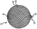
图2示出了根据本发明的一个或多个示范实施例的编织物球的侧透视图。2 illustrates a side perspective view of a ball of braid in accordance with one or more exemplary embodiments of the present invention.
图3示出了根据本发明的一个或多个示范实施例的在分叉动脉瘤内被展开的编织物球植入物的侧剖视图。3 illustrates a side cross-sectional view of a braided ball implant deployed within a bifurcated aneurysm in accordance with one or more exemplary embodiments of the present invention.
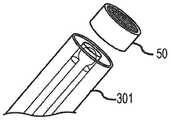
图4示出了根据本发明的一个或多个示范实施例的输送系统的远端的局部侧剖视图。4 illustrates a partial side cross-sectional view of the distal end of a delivery system in accordance with one or more exemplary embodiments of the present invention.
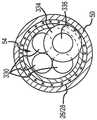
图5示出了根据本发明的一个或多个示范实施例的图4中所示系统的植入物内观察的端视图。5 illustrates an end view viewed within the implant of the system shown in FIG. 4 in accordance with one or more exemplary embodiments of the present invention.
图6A,6B,6C,6D,6E和6F示出了根据本发明的一个或多个示范实施例的与系统分离的植入物的局部透视图。6A, 6B, 6C, 6D, 6E and 6F show partial perspective views of an implant separated from the system in accordance with one or more exemplary embodiments of the present invention.
图7和8示出了根据本发明的一个或多个示范实施例的血管输送系统的侧透视图。7 and 8 illustrate side perspective views of a vascular delivery system in accordance with one or more exemplary embodiments of the present invention.
图9示出了根据本发明的一个或多个示范实施例的血管输送系统的侧透视图。9 illustrates a side perspective view of a vascular delivery system in accordance with one or more exemplary embodiments of the present invention.
图10A,10B,和10C示出了根据本发明的一个或多个示范实施例的具有半圆形线轮廓的血管输送系统的侧透视图。10A, 10B, and 10C illustrate side perspective views of a vascular delivery system having a semicircular wire profile in accordance with one or more exemplary embodiments of the present invention.
图11A,11B,11C和11D示出了根据本发明的一个或多个示范实施例的具有半圆形线轮廓的血管输送系统的侧透视图。Figures 11A, 11B, 11C and 11D illustrate side perspective views of a vascular delivery system having a semicircular wire profile in accordance with one or more exemplary embodiments of the present invention.
图12A,12B,和12C示出了根据本发明的一个或多个示范实施例的具有内置夹头锁的血管输送系统的侧透视图。12A, 12B, and 12C illustrate side perspective views of a vascular delivery system with a built-in collet lock in accordance with one or more exemplary embodiments of the present invention.
图13A,13B,和13C示出了根据本发明的一个或多个示范实施例的具有管锁的血管输送系统的侧透视图。13A, 13B, and 13C illustrate side perspective views of a vascular delivery system with a tube lock in accordance with one or more exemplary embodiments of the present invention.
图14A示出了根据本发明的一个或多个示范实施例的具有互锁管的血管输送系统的侧视图。14A shows a side view of a vascular delivery system with interlocking tubes in accordance with one or more exemplary embodiments of the present invention.
图14B示出了根据本发明的一个或多个示范实施例的具有互锁管的血管输送系统的前视图。14B shows a front view of a vascular delivery system with interlocking tubes in accordance with one or more exemplary embodiments of the present invention.
图14C示出了根据本发明的一个或多个示范实施例的具有互锁管的血管输送系统的顶视图。14C shows a top view of a vascular delivery system with interlocking tubes in accordance with one or more exemplary embodiments of the present invention.
图14D示出了根据本发明的一个或多个示范实施例的具有互锁管的血管输送系统的侧剖视图。14D illustrates a side cross-sectional view of a vascular delivery system with interlocking tubes in accordance with one or more exemplary embodiments of the present invention.
图14E示出了根据本发明的一个或多个示范实施例的具有互锁管的血管输送系统的侧视图。14E shows a side view of a vascular delivery system with interlocking tubes in accordance with one or more exemplary embodiments of the present invention.
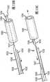
图15A示出了根据本发明的一个或多个示范实施例的具有互锁管的血管输送系统的侧视图。15A shows a side view of a vascular delivery system with interlocking tubes in accordance with one or more exemplary embodiments of the present invention.
图15B示出了根据本发明的一个或多个示范实施例的具有互锁管的血管输送系统的前视图。15B shows a front view of a vascular delivery system with interlocking tubes in accordance with one or more exemplary embodiments of the present invention.
图15C示出了根据本发明的一个或多个示范实施例的具有互锁管的血管输送系统的顶视图。15C shows a top view of a vascular delivery system with interlocking tubes in accordance with one or more exemplary embodiments of the present invention.
图15D示出了根据本发明的一个或多个示范实施例的具有互锁管的血管输送系统的侧剖视图。15D illustrates a side cross-sectional view of a vascular delivery system with interlocking tubes in accordance with one or more exemplary embodiments of the present invention.
图15E示出了根据本发明的一个或多个示范实施例的具有互锁管的血管输送系统的侧视图。15E shows a side view of a vascular delivery system with interlocking tubes in accordance with one or more exemplary embodiments of the present invention.
图16A和16B示出了根据本发明的一个或多个示范实施例的具有桨叶锁的血管输送系统的侧透视图。16A and 16B illustrate side perspective views of a vascular delivery system with a paddle lock in accordance with one or more exemplary embodiments of the present invention.
具体实施方式Detailed ways
在下面的详述中,具体的细节被给出以提供本发明的理解。但是,对于本领域技术人员明显的是,本发明能在缺少某些具体细节的情况下能够被实施。另外,已知的结构和技术没有被详细地示出以免模糊本发明。In the following detailed description, specific details are set forth to provide an understanding of the present invention. However, it will be apparent to those skilled in the art that the present invention can be practiced without certain specific details. Additionally, well-known structures and techniques have not been shown in detail in order not to obscure the present invention.
词语“一个方案”不意味该方案对本发明是必要的,或者该方案适用于本发明的所有配置。涉及一个方案的公开能适用于所有配置,或者一个或多个配置。一个方案能提供本发明的一个或多个示例。词语“一个方案”能涉及一个或多个方案,反之亦然。词语“一个实施例”不意味该实施例对本发明是必要的,或者该实施例适用于本发明的所有配置。涉及一个实施例的公开能适用于所有实施例,或一个或多个实施例。一个实施例能提供本发明的一个或多个示例。词语“一个实施例”能涉及一个或多个实施例,反之亦然。词语“一个配置”不意味该配置对本发明是必要的,或者该配置适用于本发明的所有配置。涉及一个配置的公开能适用于所有配置,或一个或多个配置。一个配置能提供本发明的一个或多个示例。词语“一个配置”能涉及一个或多个配置,反之亦然。The word "a solution" does not mean that the solution is essential to the invention, or that the solution is applicable to all configurations of the invention. A disclosure involving one solution can apply to all configurations, or to one or more configurations. An aspect can provide one or more examples of the invention. The term "a scheme" can refer to one or more schemes and vice versa. The word "one embodiment" does not mean that the embodiment is essential to the present invention or that the embodiment is applicable to all configurations of the present invention. A disclosure relating to one embodiment can apply to all embodiments, or one or more embodiments. An embodiment can provide one or more examples of the invention. The term "one embodiment" can refer to one or more embodiments, and vice versa. The word "a configuration" does not mean that the configuration is essential to the present invention, or that the configuration is applicable to all configurations of the present invention. A disclosure involving one configuration can apply to all configurations, or one or more configurations. A configuration can provide one or more instances of the invention. The term "a configuration" can refer to one or more configurations and vice versa.
根据部分示范实施例,图1展示了包括植入物20和手柄342的治疗系统300的概况。这些中之一或两者能根据本文中的教导进行构造。所示的手柄342包括连接到分离机构(例如,线)的旋钮,分离机构接合植入物20。两个旋钮344被连接到控制线(未示出),最末旋钮346被连接到锚定线(未示出)。可拆卸锁定盖348和应变消除段350可以被包含在手柄设计中。导管/推进器轴301可以包括简单的挤出部(例如,PTFE,FEP,PEEK,等),或可以采用常规导管构造技术进行构造,且包括内衬、编织物支撑件和外套(未示出)。装载护套352通常被设置在推进器301的轴上。FIG. 1 illustrates an overview of a
根据部分示范实施例,如图2和3所示,由系统300输送的植入物20可以是编织物球。编织物球20可以由包含弹性材料(比如钛镍合金)的管状编织物原料形成,编织物球在未压缩/未受约束状态下限定了开放容积(大致圆形、球形、卵形、心形等)。植入物的尺寸可以被选择成填满动脉瘤2,所以该装置的近端52有助于引导血液沿构造成植入物的编织物的表面流动到支血管8。球的远端56是穹顶形。编织物球20可以至少在动脉瘤2的颈部10处受流动影响的位置包括单层或双层26,28(分别是内层和外层)结构。如所示,一圈或多圈线圈(例如,Pt线)或一个条带(未示出)能提供远侧的不透辐射结构以标记植入物20的位置。能配合本文中所描述的系统使用的部分示范植入物在2013年5月16日公开的美国专利公开No.2013/0123830中公开,以提及的方式将其全部内容并入本文。According to some exemplary embodiments, as shown in FIGS. 2 and 3 , the
根据部分示范实施例,植入物20可以在其近端52处包括套节50。套节50可以被固定地附接到植入物20的其余部分。例如,套节50能抓住植入物20的层26,28的编织丝。套节50能提供管腔54用于接收输送系统的接合与释放机构。According to some exemplary embodiments,
根据部分示范实施例,植入物20能被设置在位于血管分叉部4处的动脉瘤囊2内,血管分叉部由大血管8和输出血管8形成。植入物20能通过穿过大血管8(例如,基底动脉)的路径被输送,优选地穿过带有下面所详述的输送系统的市售微导管。为了输送植入物20,推进器套筒301被定位成使得植入物20能至少部分地被输送到动脉瘤囊2内。在最终定位完成后,如图3所示,接合构件从植入物20上被释放(例如从植入物20的套节50上),如下面进一步讨论那样。最后,推进器套筒301撤回到输送导管352内。According to some exemplary embodiments, the
虽然如在本文中所示,植入物20可以是一种编织物球,但是根据多种实施例,植入物20能具有任何其他的形式或结构。例如,植入物20可以是血管闭塞线圈、圆柱形的管状支架、或者过滤器。其他类型的植入物是已知的。本发明能被应用于输送和分离的植入物。例如,一种指定的植入物可以包括通过输送系统进行接合与释放的套节50,如本文中进一步公开那样。Although as shown herein, the
示范可分离输送系统300在图4和5中被示出。根据部分示范实施例,一个或多个控制线332和锚定线336部分地或完全地延伸穿过植入物20的套节50的管腔54。锚定线336可以包括相对于控制线332的远侧部330或锚定线336的近侧部之一或两者具有扩大截面尺寸(例如,直径)的头部334。头部334可以位于锚定线336的远侧部或最远侧部。除非一个或多个控制线332被从管腔54移除,否则安装在锚定线336上的所述头部334不能穿过管腔54。控制线332能延伸到或越过锚定线头部334。An exemplary
图6A-6F示出了使用中的输送系统300的操作。分离系统的远端被示出带有植入物20的套节50。图6A示出了被互锁接合的推进器301。图6B-6D示出了控制线332的顺序撤出。因为所述线被笔直拉出,所以只需要定位锚定线头部334以保证最小代价的干涉。能提供至少在控制线332上的EPTFE涂层以促进移除。锚定线336也能被独立地撤出,如图6E所示。但是,锚定线能随分离系统套筒301一起撤出。应当意识到,控制线332不必一次只拉动一个,而是能一起致动。完整的植入物(例如套节50)分离在图6F中示出。6A-6F illustrate the operation of the
根据部分示范实施例,如图7所示,血管输送系统700可以包括限定了端口754的植入物套节750,该端口具有内侧截面尺寸。锚定线736能延伸穿过所述端口754,从而扩大的锚定部734被定位在所述端口754和所述套节750的远侧。扩大的锚定部734具有大于锚定线近侧部的截面尺寸的锚定截面尺寸。一个或多个控制线732能延伸穿过所述端口754,从而位于每个控制线732的远侧部或最远侧部的接合部730被定位在所述端口754和套节750的远侧。远端730具有接合截面尺寸。所述接合部730相对于锚定部734是可朝近侧收回的。锚定部734被配置成保持在端口754的远侧,直到接合部730被朝近侧收回越过所述端口754为止。根据部分示范实施例,端口754的内侧截面尺寸小于锚定部734的锚定截面尺寸和接合部730的接合截面尺寸的总和。According to some exemplary embodiments, as shown in FIG. 7, a
根据部分示范实施例,锚定线736是第一材料的,控制线732是比第一材料更柔性的第二材料的,从而接合部730被配置成在套节750远侧的区域处偏转远离锚定部734和系统700的纵轴线,同时锚定部734保持与所述纵轴线对齐。示范性输送系统700可以包括超弹性镍钛合金控制线732和刚性不锈钢锚定线736。According to some exemplary embodiments,
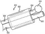
根据部分示范实施例,如图8中所示,血管输送系统800可以包括限定了端口854的植入物套节850,该端口具有内侧截面尺寸。锚定线836延伸穿过端口854,从而扩大的锚定部834被定位在端口854和套节850的远侧。扩大的锚定部834具有大于锚定线近侧部的截面尺寸的锚定截面尺寸。一个或多个控制线832能延伸穿过所述端口854,从而位于每个控制线832的远侧部或最远侧部的接合部830被定位在所述端口854和套节850的远侧。远端830具有接合截面尺寸。所述接合部830相对于锚定部834是可朝近侧收回的。锚定部834被配置成保持在端口854的远侧,直到接合部830被朝近侧收回越过所述端口854为止。根据部分示范实施例,端口854的内侧截面尺寸小于锚定部834的锚定截面尺寸和接合部830的接合截面尺寸的总和。According to some exemplary embodiments, as shown in FIG. 8, a
根据部分示范实施例,锚定线836是第一材料的,控制线832是比第一材料更不柔性的第二材料的,从而锚定部834被配置成在套节850远侧的区域处偏转远离接合部830和系统800的纵轴线,同时控制线832保持与所述纵轴线对齐。示范性输送系统800可以包括超弹性镍钛合金锚定线836和刚性不锈钢控制线832。According to some exemplary embodiments,
镍钛合金锚定线836的提供允许锚定线836在植入物套节内具有更小的截面,同时在分离期间在锚定部834处提供锚定线836的超弹性恢复,以易于与植入物(例如套节850)分离。不锈钢具有比镍钛合金更高的弹性模量。控制线832采用不锈钢,这为控制线832提供更高的刚度,同时减少控制线在植入物分离期间的拉长。相对刚性的控制线832比较不可能弯折碰到套节850的端口854的边缘,从而减少了摩擦以及减少了控制线832在分离期间的拉长和拉伸。The provision of the
镍钛合金锚定线836的几何形状能采用多种形式。在内侧套节850的远端处产生干涉配合的末端可以通过焊接工艺被形成为球体,或者可以通过轮廓磨削工艺被定形为各种几何形状。通往所述末端的轴也可以被研磨或电化学加工到较小的截面,或沿内侧套节长度或越过内侧套节长度渐缩,从而减少套节内的摩擦力以及降低输送系统远端处的弯曲刚度。The geometry of the
根据部分示范实施例,如图9中所示,血管输送系统900包括限定了端口954的植入物套节950,该端口具有内侧截面尺寸。锚定线936能延伸穿过端口954,从而扩大的锚定部934被定位在端口954和套节950的远侧。扩大的锚定部934具有大于锚定线近侧部的截面尺寸的锚定截面尺寸。一个或多个控制线932能延伸穿过所述端口954,从而位于每个控制线932的远侧部或最远侧部的接合部930被定位在所述端口954和套节950的远侧。远端930具有接合截面尺寸。所述接合部930相对于锚定部934是可朝近侧收回的。锚定部934被配置成保持在端口954的远侧,直到接合部930被朝近侧收回越过所述端口954为止。根据部分示范实施例,端口954的内侧截面尺寸小于锚定部934的锚定截面尺寸和接合部930的接合截面尺寸的总和。According to some exemplary embodiments, as shown in FIG. 9, a
根据部分示范实施例,锚定线936包括在锚定部934近侧的颈部937,颈部具有小于锚定部934的锚定截面尺寸的颈部截面尺寸。锚定线936还包括在所述颈部937近侧的近侧部935,该近侧部具有大于颈部937的颈部截面尺寸的近侧截面尺寸。当处于接合构型时,套节950轴向地位于近侧部935和锚定部934之间。套节950的轴向运动朝远侧方向由锚定部934限制。套节950的轴向运动朝近侧方向由近侧部935限制。所述限制能够通过移除锚定线932被解除。According to some exemplary embodiments,
根据部分示范实施例,利用在穿过植入物套节950的颈部937处具有缩小颈部截面的锚定线936(例如镍钛合金的),这实现了通过控制线932(例如不锈钢的)使锚定部934快速偏转,且随着锚定部934朝纵轴线的主动返回而轻易地解除偏转。锚定线936的较低刚度也减少了对控制线932的侧向摩擦力,以用于在控制线932上的拉伸负荷较低的情况下更可靠地与植入物套节950分离。According to some exemplary embodiments, this is accomplished through control wire 932 (eg, stainless steel) with anchor wire 936 (eg, of Nitinol) having a reduced neck cross-section at
根据部分示范实施例,如图10A-10C中所示,血管输送系统1000可以包括限定了端口1054的植入物套节1050,该端口具有内侧截面尺寸。锚定线1036能延伸穿过端口1054,从而扩大的锚定部1034被定位在端口1054和套节1050的远侧。扩大的锚定部1034具有大于锚定线近侧部的截面尺寸的锚定截面尺寸。一个或多个控制线1032能延伸穿过所述端口1054,从而位于每个控制线1032的远侧部或最远侧部的接合部1030被定位在所述端口1054和套节1050的远侧。远端1030具有接合截面尺寸。所述接合部1030相对于锚定部1034是可朝近侧收回的。锚定部1034被配置成保持在端口1054的远侧,直到接合部1030被朝近侧收回越过所述端口1054为止。根据部分示范实施例,端口1054的内侧截面尺寸小于锚定部1034的锚定截面尺寸和接合部1030的接合截面尺寸的总和。According to some exemplary embodiments, as shown in FIGS. 10A-10C , a
根据部分示范实施例,锚定线1036包括在锚定部1034的近侧的颈部1037,颈部具有小于锚定部1034的锚定截面尺寸的颈部截面尺寸。锚定线1036还包括在所述颈部1037近侧的近侧部1035,该近侧部具有大于颈部1037的颈部截面尺寸的近侧截面尺寸。According to some exemplary embodiments,
根据部分示范实施例,锚定线1036具有第一纵向延伸平坦表面1035,控制线1032具有面朝所述锚定线1036的第一纵向延伸平坦表面的第二纵向延伸平坦表面1031。锚定线1036和控制线1032的每一个都可以包括平坦表面和弯曲表面。当以所述平坦表面彼此面对的方式被布置时,控制线1032和锚定线1036能在截面上产生一种几何形状。例如,锚定线1036和控制线1032的每一个能在截面上能形成半圆形(半圆轮廓),从而它们在截面上共同形成一个完整的圆。示范性实施例对锚定线和控制线采用了半圆形轮廓,同时消除了某些示范输送系统的额外“虚设”线。According to some exemplary embodiments, the
对锚定线和控制线应用半圆形线轮廓消除了对输送系统中“虚设”线的需求。所述“虚设”线被用于阻止控制线和锚定线在输送轴的长度上彼此缠绕。半圆形轮廓能防止在输送系统轴内一条线缠绕另一条。半圆形轮廓还能减少控制线和锚定线自身之间的摩擦力,以及缩小输送系统的内径。半圆形轮廓还将减少输送系统的总体刚度,同时不牺牲关键的控制线/锚定线元件的强度。Applying semicircular wire profiles to anchor and control wires eliminates the need for "dummy" wires in the conveyor system. The "dummy" wire is used to prevent the control wire and the anchor wire from wrapping around each other over the length of the delivery shaft. The semi-circular profile prevents one wire from wrapping around the other in the shaft of the conveyor system. The semi-circular profile also reduces friction between the control wire and the anchor wire itself, as well as reducing the inner diameter of the delivery system. The semi-circular profile will also reduce the overall stiffness of the delivery system without sacrificing the strength of critical control wire/anchor wire elements.
以半圆形锚定线和/或控制线取代三根圆形线能够实现仅以两根线进行输送、以及可能减少输送轴管腔中的摩擦和硬度。如图10B和10C中所示,控制线1032的朝近侧撤出实现了后续的锚定线1036的朝近侧撤出。Replacing the three circular wires with semi-circular anchor wires and/or control wires enables delivery with only two wires, and potentially reduces friction and stiffness in the delivery shaft lumen. As shown in FIGS. 10B and 10C , proximal withdrawal of the
一个示范性系统采用了几乎填满整个0.010的输送轴管腔的三根0.004的圆线(第三根线未示出,因为它留在植入物套节近侧的输送轴内)。具有0.008英寸大直径和0.004英寸小直径的两根半圆线允许在已有的输送轴内周向地留有0.002英寸的间隙,从而在不降低控制线/锚定线元件强度的前提下减小了摩擦力。锚定线/控制线元件之间以及它们与输送系统内径之间的摩擦力预计将被减少。也可预期到沿输送系统整个长度的输送系统刚度的降低。An exemplary system employs three 0.004 round wires that fill nearly the entire 0.010 lumen of the delivery shaft (the third wire is not shown because it remains in the delivery shaft proximal to the implant hub). Two semicircular wires with a large diameter of 0.008" and a small diameter of 0.004" allow for a 0.002" clearance circumferentially within the existing delivery shaft, reducing the strength of the control wire/anchor wire elements without reducing the strength of the friction. The friction between the anchor wire/control wire elements and between them and the inner diameter of the delivery system is expected to be reduced. A reduction in the stiffness of the delivery system along the entire length of the delivery system is also expected.
一个示范输送系统通过使用在输送系统手柄内的滑动器部件使三根线依次地相对于彼此移动。因为虚设线被首先收回,所以对锚定线和控制线的摩擦倾向于使它们朝近侧移动,从而增大锚定线和控制线与植入物套节的锁合力。因此在锚定线被最终释放之前,控制线必须克服额外的拉伸力才能被移除。采用半圆形锚定线和控制线能消除部分或所有的不需要的摩擦力和锁合力。One exemplary delivery system moves three wires sequentially relative to each other by using a slider member within the handle of the delivery system. Because the dummy wires are retracted first, friction against the anchor and control wires tends to move them proximally, increasing the locking force of the anchor and control wires to the implant hub. Therefore, the control wire must overcome the additional tensile force to be removed before the anchor wire is finally released. The use of semicircular anchor wires and control wires can eliminate some or all of the unwanted friction and locking forces.
根据部分示范实施例,如图11A-11D中所示,血管输送系统1100包括限定了端口1154的植入物套节1150,该端口具有内侧截面尺寸。锚定线1136能延伸穿过端口1154,从而扩大的锚定部1134被定位在端口1154和套节1150的远侧。扩大的锚定部1134具有大于锚定线近侧部的截面尺寸的锚定截面尺寸。一个或多个控制线1132能延伸穿过所述端口1154,从而位于每个控制线1132的远侧部或最远侧部的接合部1130被定位在所述端口1154和套节1150的远侧。远端1130具有接合截面尺寸。所述接合部1130相对于锚定部1134是可朝近侧收回的。锚定部1134被配置成保持在端口1154的远侧,直到接合部1130被朝近侧收回越过所述端口1154为止。根据部分示范实施例,端口1154的内侧截面尺寸小于锚定部1134的锚定截面尺寸和接合部1130的接合截面尺寸的总和。According to some exemplary embodiments, as shown in FIGS. 11A-11D , a
根据部分示范实施例,锚定线1136包括在锚定部1134近侧的颈部1137,颈部具有小于锚定部1134的锚定截面尺寸的颈部截面尺寸。锚定线1136还包括在所述颈部1137近侧的近侧部1135,该近侧部具有大于颈部1137的颈部截面尺寸的近侧截面尺寸。根据部分示范实施例,锚定线1136具有第一纵向延伸平坦表面1135,控制线1132具有面朝所述锚定线1136的第一纵向延伸平坦表面的第二纵向延伸平坦表面1131。According to some exemplary embodiments,
根据部分示范实施例,为了进一步提高半圆线元件的性能,采用推拉机构。例如,锚定线1136能被定位成使得所述锚定部1134抵接端口1154的远侧边缘,如图11A中所示。锚定部1134能通过作用在锚定线1136上的可控或恒定朝近侧的作用力被保持在该位置。例如,弹簧或其他机构(例如,在手柄内,未示出)能提供作用在锚定线1136上的朝近侧指向的作用力。因为锚定部1134抵接端口1154的远侧边缘,所以锚定部1134或锚定线1136的其他部分接合控制线1132,从而将接合部1130压迫在端口1154上,从在它们之间产生摩擦或干涉配合。如图11B中所示,锚定线1136能由使用者朝远侧推进,从而解锁套节1150内的锚定线/控制线组件的干涉配合。接下来或同时,控制线1132被朝近侧收回离开套节1150,如图11C中所示。最后,锚定线1136被拉出套节1150,从而使植入物分离,如图11D中所示。According to some exemplary embodiments, in order to further improve the performance of the semicircular wire element, a push-pull mechanism is employed. For example, the
根据部分示范实施例,如图12A-12C中所示,血管输送系统1200包括限定了端口1254的植入物套节1250,该端口具有内侧截面尺寸。轴1236延伸穿过套节1250,且包括在该轴1236的远端处、在套节1250和端口1254远侧的夹头1235。夹头1235提供多个延伸部1234。延伸部1234通过在轴1236的远端处切入该轴的切口形成。控制线1232延伸穿过轴1236的管腔1239和夹头1235。控制线1232具有位于夹头1235的至少一部分远侧的接合部1230,该接合部具有大于位于接合部1230近侧的控制线1232部分的截面尺寸的接合截面尺寸。夹头1235能处于具有张开外截面尺寸和张开内截面尺寸的张开状态。夹头1235能处于具有小于所述张开外截面尺寸的松弛外截面尺寸和松弛内截面尺寸的松弛状态。所述张开外截面尺寸和松弛外截面尺寸由延伸部1234在各状态下的最大径向截面尺寸限定。张开内截面尺寸和松弛内截面尺寸由穿过夹头1235的管腔1239的径向大小限定。According to some exemplary embodiments, as shown in Figures 12A-12C,
如图12A和12B中所示,接合部1230的接合截面尺寸大于管腔1239在夹头1235处的松弛内截面尺寸。所以,当接合部1230逆着夹头1235被朝近侧移动时,夹头1235的延伸部1234从松弛状态转变为张开状态。根据部分示范实施例,端口1254的内侧截面尺寸小于夹头1235的张开外截面尺寸。所以在张开状态下以及当接合部1230抵接夹头1235的延伸部1234时,轴1236被阻止相对套节1250朝近侧移动穿过该套节。在张开状态下,夹头1235被配置成保持在端口1254的远侧。As shown in FIGS. 12A and 12B , the engaged cross-sectional dimension of the
根据部分示范实施例,张开外截面尺寸大于端口1254的内侧截面尺寸,松弛外截面尺寸小于或等于端口1254的内侧截面尺寸。根据部分示范实施例,夹头1235包括多个从轴的近侧段延伸的指状部。根据部分示范实施例,当不受约束时夹头1235被偏压以呈现松弛状态。According to some exemplary embodiments, the flared outer cross-sectional dimension is greater than the inner cross-sectional dimension of
参见图12A,12B,和12C,示范实施例包括带有夹头1235的镍钛合金管1236,夹头具有在远端上切割出的(例如,通过激光)且在不受约束时被笔直定形(例如,平行于纵轴线)的多个指状结构1234。镍钛合金管1236被附接到输送系统轴120的远端,且在植入物的套节1250内可滑动。当轴向定位的弹簧所加载的控制线1232(其具有扩大末端1230)被(朝近侧)拉回到指状部1234内时,指状结构1234朝外变形,从而在内侧套节1250的远端处将植入物和套节1250锁定到输送系统1201。当控制线1232被向前(朝远侧)推进时,指状部1234超弹性地恢复到它们的笔直构型,从而允许控制线1232和镍钛合金管滑出植入物套节1250,使植入物与输送系统分离,如图12C所示。Referring to Figures 12A, 12B, and 12C, the exemplary embodiment includes a
以内置夹头系统取代示范的三根圆线,这能实现一种单线输送系统、以及可能减小输送轴管腔中的摩擦与刚度。一个示范的三线系统在分离过程期间需要三个独立的线元件超过几厘米的相对运动。内置夹头系统只需要移动一根线,且位移被限制在大约1mm的行程。因为只有一根线被移动,所以它的直径被增大以提供更大的柱刚度用于推进。Replacing the exemplary three round wires with a built-in collet system enables a single wire delivery system and potentially reduces friction and stiffness in the delivery shaft lumen. An exemplary three-wire system requires relative movement of the three individual wire elements over several centimeters during the separation process. The built-in collet system requires only one wire to move, and displacement is limited to approximately 1mm of travel. Because only one wire is moved, its diameter is increased to provide greater column stiffness for propulsion.
根据部分示范实施例,控制线1232的末端几何形状能采取多种形式,例如,球形端、或锥形桩。控制线1232和内置夹头1235能通过电镀被制造得更加不透辐射,或者针对控制线1323以贵金属进行填充,从而在展开/分离期间提供更佳的荧光镜可见度。According to some exemplary embodiments, the end geometry of
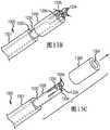
根据部分示范实施例,如图13A-13C中所示,血管输送系统1300可以包括限定了端口1354的植入物套节1350,该端口具有内侧截面尺寸。轴1336具有包括多个在端口1354远侧的延伸部1334在内的干涉段,延伸部具有带延伸内截面尺寸和延伸外截面尺寸的延伸状态(图13A),和带松弛内截面尺寸和小于所述延伸外截面尺寸的松弛外截面尺寸的松弛状态(图13B)。张开外截面尺寸和松弛外截面尺寸能由延伸部1334在各状态下的最大径向截面尺寸(包含横跨位于一个或多个延伸部1334的外表面上的突起1335的测量值)限定。所述突起1335可以被形成在延伸部1334的最远侧末端处或在延伸部1334的最远侧末端的近侧位置处。所述突起1335可以是单一材料体或者成图案的材料体。张开内截面尺寸和松弛内截面尺寸由穿过轴1336的管腔1339的径向大小限定。According to some exemplary embodiments, as shown in Figures 13A-13C,
根据部分示范实施例,控制线1332延伸穿过轴1336的管腔1339且可选地越过延伸部1334。当控制线1332的接合部1330穿过管腔1339至少延伸到一个或多个突起1335的位置(干涉段)时,轴1336呈现扩张状态,从而形成延伸外截面尺寸和延伸内截面尺寸。例如,接合部1330的外截面尺寸大于轴1336的松弛内截面尺寸,从而接合部径向向外地推动至少一些延伸部1334从松弛状态到扩张状态。干涉段被配置成在处于扩张状态时保持在端口1354的远侧。根据部分示范实施例,延伸截面尺寸由一对延伸部1334的突起1335之间的、从系统中心轴线径向向外延伸的距离限定。According to some exemplary embodiments,
根据部分示范实施例,位于干涉段近侧的接合部1330的朝近侧收回致使干涉段的延伸部1334从扩张状态转变为松弛状态。根据部分示范实施例,干涉段被偏压以在不受约束时呈现松弛状态。According to some exemplary embodiments, proximal retraction of
参见图13A,13B,和13C,示范实施例包括镍钛合金管1336,该管具有在管的远端上切割出的双侧孔。细铂线被推动穿过所述孔并被焊接从而在管的外表面上双侧地形成小干涉结构1335。留在管内径中的铂线被心轴切断。在铂珠的任一侧远端上切出激光切割槽,从而形成指状结构以及不受约束时的偏内定形。镍钛合金管1336被附接到输送系统护套1301的远端,且在植入物的套节1350内可滑动。当轴向定位的控制线1332被(朝远侧)推动超出指状部1334的长度时,携带焊接铂珠的指状结构被向外变形,所述铂珠在内侧套节1350的远端处将植入物锁定到输送系统。当控制线1332被(朝近侧)拉回时,指状部超弹性地恢复到它们的偏内构型,从而允许控制线1332和镍钛合金管1336滑出植入物套节1350,使植入物与输送系统分离。Referring to Figures 13A, 13B, and 13C, the exemplary embodiment includes a
以管锁系统取代三根圆线,这能实现一种单线输送系统、以及可能减小输送轴管腔中的摩擦与刚度。一个示范的三线系统在分离过程期间需要三个独立的线元件超过几厘米的相对运动。管锁系统只需要移动一根线,且位移被限制在大约2mm的行程。因为只有一根线被移动,所以它的直径被增大以提供更大的抗拉强度用于释放植入物。Replacing the three round wires with a tube lock system enables a single wire delivery system and potentially reduces friction and stiffness in the delivery shaft lumen. An exemplary three-wire system requires relative movement of the three individual wire elements over several centimeters during the separation process. The tube lock system requires only one wire to move, and displacement is limited to approximately 2mm of travel. Because only one wire is moved, its diameter is increased to provide greater tensile strength for releasing the implant.
根据部分示范实施例,控制线1332和镍钛合金管1336能通过电镀被制造得更加不透辐射,或者针对控制线以贵金属进行填充,从而在展开/分离期间提供更佳的荧光镜可见度。According to some exemplary embodiments, the
参见图13A,13B,和13C,干涉结构1335能通过多种其他材料的焊接被形成。替换地,干涉结构能被制造为磁性的,从而它们在控制线1332被移除后彼此吸引。在该示范实施例中,所述被定形的镍钛合金管1336被其他低模量材料所取代,从而干涉结构1335能在磁场的影响下轻易地恢复到中线。Referring to Figures 13A, 13B, and 13C,
根据部分示范实施例,如图14A-14E中所示,血管输送系统1400可以包括限定了管腔1454和键孔1452的植入物套节1450,所述键孔径向延伸穿过该套节1450的壁。系统1400还可以包括具有附加部1434的轴1436,所述附加部在偏转状态下被接合在该键孔1452内,在松弛状态下完全位于管腔1454内。控制线1432能在管腔1454内延伸,控制线1432具有相对于附加部1434能可控地朝近侧收回的接合部。当控制线1432径向靠近附加部1434时,控制线1432的接合部将所述附加部1434偏置到偏转状态。附加部1434被配置成在控制线1432的接合部被朝近侧收回越过附加部1434后实现松弛状态,如图14E中所示。根据部分示范实施例,当所述附加部1434被接合在所述键孔1452内时,套节1450相对轴1436被固定。According to some exemplary embodiments, as shown in FIGS. 14A-14E , a
根据部分示范实施例,提供两个管,一个被固定到输送系统,另一个被结合到植入物。输送系统管1436由镍钛合金制成并具有用于键合第二管1450的附加部1434。输送系统管1436被热定形,从而附加部1434伸入管的内径,此时不形成键锁。心轴穿过两个管以使所述附加部1434偏转同时在两个管之间形成锁定。这通过简单的分离结构在植入物和输送系统之间产生了可靠的锁定系统。只需要移动一根线/心轴来实现分离。所述锁定附加部/键能在形状和数量上被修改。According to some exemplary embodiments, two tubes are provided, one secured to the delivery system and the other coupled to the implant. The
根据部分示范实施例,如图15A-15E中所示,血管输送系统1500可以包括限定了管腔1554和键孔1552的植入物套节1550,所述键孔径向延伸穿过该套节1550的壁。系统1500还可以包括具有第一附加部1534a和第二附加部1534b的轴1536,所述附加部在偏转状态下被分别接合在第一键孔1552a和第二键孔1552b内,在松弛状态下完全位于管腔1554内。控制线1532能在管腔1554内延伸,控制线1532具有相对于附加部1534a,b能可控地朝近侧收回的接合部。当控制线1532径向靠近附加部1534a,b时,控制线1532的接合部将所述附加部1534a,b偏置到偏转状态。附加部1534a,b被配置成在控制线1532的接合部被朝近侧收回越过附加部1534a,b后实现松弛状态,如图15E中所示。根据部分示范实施例,当所述附加部1534a,b被接合在所述键孔1552a,b内时,套节1550相对轴1536被固定。According to some exemplary embodiments, as shown in FIGS. 15A-15E , a
根据部分示范实施例,第二附加部1534b与第一附加部1534a轴向对齐。根据部分示范实施例,第二附加部1534b相对于第一附加部1534a轴向错开。根据部分示范实施例,第二附加部1534b与第一附加部1534a径向对置。根据部分示范实施例,设置三个或多个附加部1534以及对应的键孔1552。According to some exemplary embodiments, the
根据部分示范实施例,如图16A和16B所示,血管输送系统1600可以包括限定了一个或多个键孔1652的植入物套节1650,所述一个或多个键孔1652径向延伸穿过套节1650的壁,用于接合一个或多个附加部1634。系统1600还可以包括具有第一附加部1634a和第二附加部1634b的轴1636,所述附加部在偏转状态下被分别接合在第一键孔1652a和第二键孔1652b内,在松弛状态下径向向外延伸。约束套圈1632能在附加部1634a,b上延伸,从而将附加部从松弛状态分别偏置到键孔1652a,b内。附加部1634a,b被配置成在约束套圈1632被朝近侧收回越过附加部1634a,b后实现松弛状态,如图16B中所示。根据部分示范实施例,当所述附加部1634a,b被接合在所述键孔1652a,b内且位于约束套圈1632的管腔1664内时,套节1650相对轴1636被固定。According to some exemplary embodiments, as shown in Figures 16A and 16B, a
根据部分示范实施例,第二附加部1634b与第一附加部1634a轴向对齐。根据部分示范实施例,第二附加部1634b相对于第一附加部1634a轴向错开。根据部分示范实施例,第二附加部1634b与第一附加部1634a径向对置。根据部分示范实施例,设置三个或多个附加部1634以及对应的键孔1652。According to some exemplary embodiments, the
参见图16A和16B,示范输送系统1600可以包括系绳轴和在近端上的输送手柄,系绳轴在其远端处被附接到镍钛合金系绳1650,继而在其近端处被附接到植入物套节1650。镍钛合金系绳1650被设计为具有在远端上被激光切出且被定形以在不受约束时向外扩张的对侧桨叶结构。桨叶结构1634装配到在植入物套节1650的外条带上切出的相似形状键孔1652内,并受到聚合物约束套圈1632的约束。当约束套圈1632朝近侧收回时,桨叶1634径向向外扩张,从而从输送系统1600释放植入物套节1650。Referring to Figures 16A and 16B, an
示范实施例提供更可靠的植入物分离机构。将植入物锚定在套节的外径上允许与所述装置的更大锚定接触。因为对内径没有要求,所以取消了内径,从而为小外形装置节省了大量空间。因为所述装置在血管内被输送,所以桨叶在展开时可以自由恢复。对于两线或三线输送系统,降低或消除了控制线和锚定线在张紧状态下卡死的可能性。Exemplary embodiments provide a more reliable implant separation mechanism. Anchoring the implant on the outer diameter of the hub allows for greater anchoring contact with the device. Since there is no requirement for an inner diameter, the inner diameter is eliminated, saving a lot of space for small-profile devices. Because the device is delivered intravascularly, the paddle is free to recover when deployed. For two- or three-line conveying systems, the possibility of control and anchor lines getting stuck under tension is reduced or eliminated.
根据部分示范实施例,所述桨叶结构可以具有多种其他形状,例如矩形、卵形、或泪滴形。约束所述桨叶的构件(套圈管)能够由包括金属在内的其他材料制成。套圈管能被加工成具有互锁结构以提供更大的柔性。被定形的镍钛合金桨叶结构能通过电镀金或钽被制造得更不透辐射,从而获得更好的分离荧光镜可视化。According to some exemplary embodiments, the paddle structure may have a variety of other shapes, such as rectangular, oval, or teardrop-shaped. The member (the ferrule tube) that constrains the blade can be made of other materials including metal. The ferrule tube can be machined with an interlocking structure to provide greater flexibility. Shaped nitinol paddle structures can be made more radiopaque by electroplating gold or tantalum for better separation fluoroscopic visualization.
如果示范装置的内径被保留,中空管腔将允许该装置经导丝输送。这将提供额外的安全结构,因为即使在植入物从输送系统完全释放后也能采用常规圈套技术将植入物套住。替换地,在植入物在动脉瘤内展开后并在最终释放之前,微线圈、栓塞球、或其他材料能经所述植入物套节被输送到植入物的内侧(作为动脉瘤闭塞的辅助)以辅助动脉瘤囊的闭塞。If the inner diameter of the demonstration device is preserved, the hollow lumen will allow the device to be delivered through the guidewire. This will provide an additional safety feature as the implant can be trapped using conventional snare techniques even after the implant is fully released from the delivery system. Alternatively, after deployment of the implant within the aneurysm and prior to eventual release, microcoils, embolic balls, or other materials can be delivered to the inside of the implant through the implant hub (as an aneurysm occlusion). adjuvant) to assist in the occlusion of the aneurysm sac.
前面的描述被提供以使本领域技术人员能实现本文中所描述的多种配置。尽管本发明已经参考多个附图和配置被具体地描述,但应当明白这些只是为了展示,而不应作为对本发明范围的限制。The foregoing description is provided to enable those skilled in the art to implement the various configurations described herein. While the present invention has been described in detail with reference to the various drawings and configurations, it should be understood that these are illustrative only and should not be taken as limitations on the scope of the present invention.
实施本发明还有很多其他的方式。在不脱离本发明范围的前提下,本文中所描述的各种功能和元件能以不同于所展示的方式被划分。对这些配置的各种改动对本领域技术人员是显而易见的,本文中所定义的基本原则能被应用于其他配置。因此,在不脱离本发明范围的前提下,本领域技术人员能对本发明做出很多改变和改动。There are many other ways of implementing the invention. The various functions and elements described herein could be divided into other ways than those shown without departing from the scope of the present invention. Various modifications to these configurations will be readily apparent to those skilled in the art, and the basic principles defined herein can be applied to other configurations. Accordingly, those skilled in the art can make numerous changes and modifications to the present invention without departing from the scope of the present invention.
应当明白在所公开的方法中的步骤的特定顺序或层次是示范性方法的一种展示。基于设计选择,应当明白所述方法中步骤的特定顺序或层次能被重新布置。有些步骤能被同时执行。后附的方法权利要求以一种简单的顺序展现了多个步骤的元素,所述权利要求不意味着被限制为所展现的具体顺序或层次。It is understood that the specific order or hierarchy of steps in the disclosed methods is an illustration of exemplary approaches. Based upon design choices, it is understood that the specific order or hierarchy of steps in the methods can be rearranged. Some steps can be performed simultaneously. The accompanying method claims present elements of the various steps in a simple order, and the claims are not meant to be limited to the specific order or hierarchy presented.
在本文中,以词语“和”或者“或”分隔任意项目的“前述多个项目的至少一个”这样的用语,是对所列的项目清单做一种整体的修饰,而不是对清单上的每个成员(即,每个项目)。用语“至少一个”不要求每个所列举项目至少选择一个;相反,该用语允许包含任何一个所述项目的至少一个,和/或所述项目的任意组合的至少一个,和/或每个项目的至少一个。例如,用语“A、B、和C的至少一个”或者“A、B、或C的至少一个”每一个都表示只有A、只有B、或只有C;A、B、和C的任意组合;和/或A、B、和C的每一个的至少一个。As used herein, the phrase "at least one of the foregoing items" separated from any item by the words "and" or "or" is intended to modify the list of items as a whole and not to the items on the list. per member (ie, per project). The phrase "at least one" does not require the selection of at least one of each of the listed items; rather, the phrase allows the inclusion of at least one of any one of said items, and/or at least one of any combination of said items, and/or each item at least one of. For example, the terms "at least one of A, B, and C" or "at least one of A, B, or C" each mean only A, only B, or only C; any combination of A, B, and C; and/or at least one of each of A, B, and C.
“顶”、“底”、“前”、“后”等在本文中被使用的术语应当被理解为一种随意的参照系,而不是普通的重力参照系。因此,顶表面、底表面、前表面、和后表面能在重力参照系中向上地、向下地、对角地、水平地延伸。The terms "top", "bottom", "front", "rear", etc. as used herein should be understood as an arbitrary frame of reference rather than a normal gravitational frame of reference. Thus, the top surface, bottom surface, front surface, and rear surface can extend up, down, diagonally, horizontally in the gravitational frame of reference.
另外,关于“包含”、“具有”等在本说明书或权利要求中被使用的词语的范围,这些词语是类似于词语“包括”在权利要求中被用作过渡词时所理解的那种包含性。In addition, with regard to the scope of words such as "comprising", "having", etc., used in this specification or in the claims, these words are similar to the meaning of the word "comprising" when used as a transition word in the claims. sex.
本文中所用的词语“示范”表示“作为一种示例、例子、或展示”。本文中作为“示范”被描述的实施例不必被理解为优选于或优势于其他实施例。As used herein, the word "exemplify" means "serving as an example, instance, or demonstration." Embodiments described herein as "exemplary" are not necessarily to be construed as preferred or advantageous over other embodiments.
以单数形式提及一个元件不表示“一个或只有一个”,除非有具体说明,相反是指“一个或多个”。阳性的代名词(例如他的)包括阴性的和无性的(例如,她的和它的),反之亦然。词语“某些”是指一个或多个。下划线的和/或斜体的标题与副标题只是为了方便而被使用,不限制本发明,且与对本发明说明书的解释没有关系。本领域技术人员已知的或即将知晓的在本文中所描述的各种配置的元件的所有结构性和功能性等同物以提及的方式被明确地纳入本文,并且被本发明所涵盖。另外,本文中所公开的内容并不献于公众,无论所述公开是否在前面的描述中明确记载。Reference to an element in the singular does not mean "one or only one" unless specifically stated, but instead means "one or more." Masculine pronouns (eg, his) include feminine and asexual (eg, her and its), and vice versa. The word "some" refers to one or more. Underlined and/or italicized headings and subheadings are used for convenience only, do not limit the invention, and have no bearing on the interpretation of the specification of the invention. All structural and functional equivalents to the elements of the various configurations described herein that are known or come to be known to those of ordinary skill in the art are expressly incorporated herein by reference and are encompassed by the present invention. In addition, nothing disclosed herein is dedicated to the public, whether or not the disclosure is expressly recited in the preceding description.
尽管本发明的某些方案和实施例已经被描述,但是这些都只是以举例的方式被呈现,并不限制本发明的范围。当然,在不脱离本发明本质的前提下,本文中所描述的新方法和系统能以多种其他的形式被实施。后附权利要求及其等同物将覆盖这些落入本发明范围和本质内的形式或改动。While certain aspects and embodiments of the inventions have been described, these have been presented by way of example only, and do not limit the scope of the inventions. Of course, the novel methods and systems described herein can be implemented in various other forms without departing from the essence of the present invention. The appended claims and their equivalents are intended to cover such forms or modifications as fall within the scope and spirit of the inventions.
Claims (7)
Applications Claiming Priority (4)
| Application Number | Priority Date | Filing Date | Title |
|---|---|---|---|
| US201361792147P | 2013-03-15 | 2013-03-15 | |
| US61/792,147 | 2013-03-15 | ||
| PCT/US2014/029647WO2014145012A2 (en) | 2013-03-15 | 2014-03-14 | Delivery and detachment mechanisms for vascular implants |
| CN201480021339.8ACN105142543B (en) | 2013-03-15 | 2014-03-14 | Mechanism for delivery and separation of vascular implants |
Related Parent Applications (1)
| Application Number | Title | Priority Date | Filing Date |
|---|---|---|---|
| CN201480021339.8ADivisionCN105142543B (en) | 2013-03-15 | 2014-03-14 | Mechanism for delivery and separation of vascular implants |
Publications (2)
| Publication Number | Publication Date |
|---|---|
| CN110169802A CN110169802A (en) | 2019-08-27 |
| CN110169802Btrue CN110169802B (en) | 2022-07-08 |
Family
ID=50897882
Family Applications (2)
| Application Number | Title | Priority Date | Filing Date |
|---|---|---|---|
| CN201910453890.4AActiveCN110169802B (en) | 2013-03-15 | 2014-03-14 | Delivery and detachment mechanism for vascular implants |
| CN201480021339.8AActiveCN105142543B (en) | 2013-03-15 | 2014-03-14 | Mechanism for delivery and separation of vascular implants |
Family Applications After (1)
| Application Number | Title | Priority Date | Filing Date |
|---|---|---|---|
| CN201480021339.8AActiveCN105142543B (en) | 2013-03-15 | 2014-03-14 | Mechanism for delivery and separation of vascular implants |
Country Status (4)
| Country | Link |
|---|---|
| US (3) | US10076336B2 (en) |
| EP (1) | EP2967576B1 (en) |
| CN (2) | CN110169802B (en) |
| WO (1) | WO2014145012A2 (en) |
Families Citing this family (65)
| Publication number | Priority date | Publication date | Assignee | Title |
|---|---|---|---|---|
| WO2014076620A2 (en) | 2012-11-14 | 2014-05-22 | Vectorious Medical Technologies Ltd. | Drift compensation for implanted capacitance-based pressure transducer |
| US10660645B2 (en) | 2013-03-15 | 2020-05-26 | Embo Medical Limited | Embolization systems |
| CN110169802B (en)* | 2013-03-15 | 2022-07-08 | 柯惠有限合伙公司 | Delivery and detachment mechanism for vascular implants |
| US10675039B2 (en) | 2013-03-15 | 2020-06-09 | Embo Medical Limited | Embolisation systems |
| KR102445703B1 (en) | 2013-03-15 | 2022-09-20 | 엠보 메디칼 리미티드 | Embolisation systems |
| US10205488B2 (en) | 2013-04-18 | 2019-02-12 | Vectorious Medical Technologies Ltd. | Low-power high-accuracy clock harvesting in inductive coupling systems |
| US10105103B2 (en) | 2013-04-18 | 2018-10-23 | Vectorious Medical Technologies Ltd. | Remotely powered sensory implant |
| US11291452B2 (en)* | 2013-06-26 | 2022-04-05 | W. L. Gore & Associates, Inc. | Medical device deployment system |
| EP3030194B1 (en)* | 2013-08-09 | 2019-03-13 | Merit Medical Systems, Inc. | Vascular filter delivery systems |
| US9918718B2 (en) | 2014-08-08 | 2018-03-20 | DePuy Synthes Products, Inc. | Embolic coil delivery system with retractable mechanical release mechanism |
| WO2016178196A2 (en) | 2015-05-07 | 2016-11-10 | Vectorious Medical Technologies Ltd. | Heart implant with septum gripper |
| WO2017011358A1 (en)* | 2015-07-10 | 2017-01-19 | Boston Scientific Scimed, Inc. | Detachable implantable devices |
| US10052108B2 (en)* | 2015-10-30 | 2018-08-21 | Incumedx, Inc. | Devices and methods for delivering an implant to a vascular disorder |
| US11090055B2 (en) | 2015-10-30 | 2021-08-17 | Incumedx Inc. | Devices and methods for delivering an implant to a vascular disorder |
| EP3398237B1 (en) | 2015-12-30 | 2020-12-02 | Vectorious Medical Technologies Ltd. | Power-efficient pressure-sensor implant |
| CN108261213B (en)* | 2016-12-30 | 2020-10-23 | 先健科技(深圳)有限公司 | Interventional medical systems, delivery devices and implantable medical devices |
| US20180303487A1 (en)* | 2017-04-19 | 2018-10-25 | Boston Scientific Scimed, Inc. | Variable length vascular occlusion system |
| US11191927B2 (en) | 2017-07-31 | 2021-12-07 | Boston Scientific Scimed, Inc. | Dilator with engagement region |
| US11000287B2 (en) | 2017-08-15 | 2021-05-11 | Boston Scientific Scimed, Inc. | Occlusive medical device system |
| CN107569267A (en)* | 2017-08-29 | 2018-01-12 | 上海心瑞医疗科技有限公司 | A kind of release device of handle control implant |
| US10874402B2 (en) | 2017-10-10 | 2020-12-29 | Boston Scientific Scimed, Inc. | Detachable RF energized occlusive device |
| US12318126B2 (en) | 2021-06-25 | 2025-06-03 | Covidien Lp | Current generator for a medical treatment system |
| US11058444B2 (en) | 2017-12-11 | 2021-07-13 | Covidien Lp | Electrically enhanced retrieval of material from vessel lumens |
| US11974752B2 (en) | 2019-12-12 | 2024-05-07 | Covidien Lp | Electrically enhanced retrieval of material from vessel lumens |
| US10874411B2 (en) | 2018-06-22 | 2020-12-29 | Covidien Lp | Electrically enhanced retrieval of material from vessel lumens |
| US10806462B2 (en) | 2017-12-21 | 2020-10-20 | DePuy Synthes Products, Inc. | Implantable medical device detachment system with split tube and cylindrical coupling |
| US11284902B2 (en) | 2018-02-01 | 2022-03-29 | Boston Scientific Scimed, Inc. | Method of making a vascular occlusion device |
| WO2019152775A1 (en) | 2018-02-01 | 2019-08-08 | Boston Scientific Scimed, Inc. | Medical device release system |
| WO2019152058A1 (en) | 2018-02-02 | 2019-08-08 | W.L.Gore & Associates, Inc. | Delivery system aid and associated systems and methods |
| EP3755237B1 (en)* | 2018-02-20 | 2022-04-27 | Boston Scientific Scimed Inc. | Medical device release system |
| US11191556B2 (en)* | 2018-03-01 | 2021-12-07 | Covidien Lp | Catheter including an expandable member |
| US11147562B2 (en) | 2018-12-12 | 2021-10-19 | DePuy Synthes Products, Inc. | Systems and methods for embolic implant detachment |
| US11612430B2 (en) | 2019-03-19 | 2023-03-28 | Covidien Lp | Electrically enhanced retrieval of material from vessel lumens |
| WO2020247650A1 (en)* | 2019-06-04 | 2020-12-10 | Viant As&O Holdings, Llc | Mechanical joining of nitinol tubes |
| US11523838B2 (en)* | 2019-06-12 | 2022-12-13 | Covidien Lp | Retrieval of material from corporeal lumens |
| US11191558B2 (en) | 2019-06-12 | 2021-12-07 | Covidien Lp | Retrieval of material from corporeal lumens |
| US11253265B2 (en)* | 2019-06-18 | 2022-02-22 | DePuy Synthes Products, Inc. | Pull wire detachment for intravascular devices |
| US11426174B2 (en) | 2019-10-03 | 2022-08-30 | DePuy Synthes Products, Inc. | Medical device delivery member with flexible stretch resistant mechanical release |
| US11207494B2 (en) | 2019-07-03 | 2021-12-28 | DePuy Synthes Products, Inc. | Medical device delivery member with flexible stretch resistant distal portion |
| JP2021016485A (en)* | 2019-07-18 | 2021-02-15 | 朝日インテック株式会社 | Implant device |
| US11672946B2 (en) | 2019-09-24 | 2023-06-13 | Boston Scientific Scimed, Inc. | Protection and actuation mechanism for controlled release of implantable embolic devices |
| US11376013B2 (en) | 2019-11-18 | 2022-07-05 | DePuy Synthes Products, Inc. | Implant delivery system with braid cup formation |
| US11395668B2 (en) | 2019-12-12 | 2022-07-26 | Covidien Lp | Electrically enhanced retrieval of material from vessel lumens |
| DE102020118301A1 (en)* | 2019-12-23 | 2021-06-24 | Femtos Gmbh | Implant for the treatment of aneurysms |
| US11457922B2 (en) | 2020-01-22 | 2022-10-04 | DePuy Synthes Products, Inc. | Medical device delivery member with flexible stretch resistant distal portion |
| US11432822B2 (en)* | 2020-02-14 | 2022-09-06 | DePuy Synthes Products, Inc. | Intravascular implant deployment system |
| CN111528956B (en)* | 2020-05-08 | 2021-06-11 | 上海申淇医疗科技股份有限公司 | Releasable spring ring |
| CN115955988A (en)* | 2020-06-25 | 2023-04-11 | 阿里亚Cv 有限公司 | Implantable device for reducing pulsatile pressure within blood vessels |
| US11951026B2 (en) | 2020-06-30 | 2024-04-09 | DePuy Synthes Products, Inc. | Implantable medical device detachment system with flexible braid section |
| EP4199840A4 (en) | 2020-08-21 | 2024-07-24 | Shape Memory Medical, Inc. | Mechanical detachment system for transcatheter devices |
| US20220183693A1 (en)* | 2020-08-31 | 2022-06-16 | Shawn P. Fojtik | Occlusive device with self-expanding struts |
| US11963713B2 (en) | 2021-06-02 | 2024-04-23 | Covidien Lp | Medical treatment system |
| US11944374B2 (en) | 2021-08-30 | 2024-04-02 | Covidien Lp | Electrical signals for retrieval of material from vessel lumens |
| CN113876368B (en)* | 2021-11-17 | 2025-08-08 | 南微医学科技股份有限公司 | A sampling forceps |
| US12076020B2 (en) | 2021-11-18 | 2024-09-03 | Covidien Lp | Retrieval of material from corporeal lumens |
| US20250135178A1 (en)* | 2021-12-01 | 2025-05-01 | Petrus Antonius Besselink | Extension system for coupling tubular devices |
| CN114344676B (en)* | 2021-12-29 | 2024-03-29 | 上海臻亿医疗科技有限公司 | Release mechanism and delivery catheter |
| US11844490B2 (en) | 2021-12-30 | 2023-12-19 | DePuy Synthes Products, Inc. | Suture linkage for inhibiting premature embolic implant deployment |
| US11937824B2 (en) | 2021-12-30 | 2024-03-26 | DePuy Synthes Products, Inc. | Implant detachment systems with a modified pull wire |
| US12011171B2 (en) | 2022-01-06 | 2024-06-18 | DePuy Synthes Products, Inc. | Systems and methods for inhibiting premature embolic implant deployment |
| US11937825B2 (en) | 2022-03-02 | 2024-03-26 | DePuy Synthes Products, Inc. | Hook wire for preventing premature embolic implant detachment |
| US12137915B2 (en) | 2022-03-03 | 2024-11-12 | DePuy Synthes Products, Inc. | Elongating wires for inhibiting premature implant detachment |
| US11937826B2 (en) | 2022-03-14 | 2024-03-26 | DePuy Synthes Products, Inc. | Proximal link wire for preventing premature implant detachment |
| US12402886B2 (en) | 2022-06-23 | 2025-09-02 | DePuy Synthes Products, Inc. | Detachment indicator for implant deployment |
| US20240032932A1 (en)* | 2022-07-29 | 2024-02-01 | Covidien Lp | Devices, systems, and methods for treating aneurysms |
Citations (8)
| Publication number | Priority date | Publication date | Assignee | Title |
|---|---|---|---|---|
| GB9715241D0 (en)* | 1997-07-18 | 1997-09-24 | Jeffree Martin A | Device for treating aneurysms |
| EP1125553A1 (en)* | 2000-02-16 | 2001-08-22 | Cordis Corporation | Aneurysm embolization device |
| CN1835716A (en)* | 2003-07-03 | 2006-09-20 | 库克公司 | Occluding device and method of occluding fluid flow through a body vessel |
| CN101589972A (en)* | 2004-02-06 | 2009-12-02 | 微温森公司 | The mechanism that is used for the deployment of endovascular implants |
| CN102014769A (en)* | 2008-04-21 | 2011-04-13 | 纽福克斯神经医疗公司 | Braided Ball Embolization Device and Delivery System |
| CN102119004A (en)* | 2008-07-15 | 2011-07-06 | 半影公司 | Embolic coil implant system |
| CN102119040A (en)* | 2008-05-02 | 2011-07-06 | 斯昆特医疗公司 | Filamentous device for treating vascular defects |
| CN102166124A (en)* | 2006-03-24 | 2011-08-31 | 奥特鲁泰克有限公司 | Occlusion instrument and method for its production |
Family Cites Families (245)
| Publication number | Priority date | Publication date | Assignee | Title |
|---|---|---|---|---|
| DE2946569A1 (en) | 1979-11-19 | 1981-05-21 | MTU Motoren- und Turbinen-Union München GmbH, 8000 München | DEVICE FOR THERMALLY SPRAYING METAL AND CERAMIC POWDERS |
| US4655219A (en)* | 1983-07-22 | 1987-04-07 | American Hospital Supply Corporation | Multicomponent flexible grasping device |
| US5480382A (en) | 1989-01-09 | 1996-01-02 | Pilot Cardiovascular Systems, Inc. | Steerable medical device |
| US5728129A (en) | 1989-02-17 | 1998-03-17 | American Biomed, Inc. | Distal atherectomy catheter |
| USRE42625E1 (en) | 1990-03-13 | 2011-08-16 | The Regents Of The University Of California | Endovascular electrolytically detachable wire and tip for the formation of thrombus in arteries, veins, aneurysms, vascular malformations and arteriovenous fistulas |
| US5354295A (en) | 1990-03-13 | 1994-10-11 | Target Therapeutics, Inc. | In an endovascular electrolytically detachable wire and tip for the formation of thrombus in arteries, veins, aneurysms, vascular malformations and arteriovenous fistulas |
| US5109867A (en) | 1991-04-19 | 1992-05-05 | Target Therapeutics | Extendable guidewire assembly |
| US5217484A (en) | 1991-06-07 | 1993-06-08 | Marks Michael P | Retractable-wire catheter device and method |
| US5234437A (en) | 1991-12-12 | 1993-08-10 | Target Therapeutics, Inc. | Detachable pusher-vasoocclusion coil assembly with threaded coupling |
| DE69230385T2 (en) | 1991-12-12 | 2000-04-06 | Target Therapeutics, Inc. | Detachable, slidable, vessel-closing spiral with interlocking coupling elements |
| US5261916A (en) | 1991-12-12 | 1993-11-16 | Target Therapeutics | Detachable pusher-vasoocclusive coil assembly with interlocking ball and keyway coupling |
| US5282806A (en) | 1992-08-21 | 1994-02-01 | Habley Medical Technology Corporation | Endoscopic surgical instrument having a removable, rotatable, end effector assembly |
| WO1993020886A1 (en) | 1992-04-13 | 1993-10-28 | Ep Technologies, Inc. | Articulated systems for cardiac ablation |
| US5263964A (en) | 1992-05-06 | 1993-11-23 | Coil Partners Ltd. | Coaxial traction detachment apparatus and method |
| US5312415A (en) | 1992-09-22 | 1994-05-17 | Target Therapeutics, Inc. | Assembly for placement of embolic coils using frictional placement |
| DK0617633T3 (en) | 1992-09-22 | 2000-04-17 | Target Therapeutics Inc | Detachable embolic spiral construction |
| US5350397A (en) | 1992-11-13 | 1994-09-27 | Target Therapeutics, Inc. | Axially detachable embolic coil assembly |
| IL106946A0 (en) | 1992-09-22 | 1993-12-28 | Target Therapeutics Inc | Detachable embolic coil assembly |
| USRE37117E1 (en) | 1992-09-22 | 2001-03-27 | Target Therapeutics, Inc. | Detachable embolic coil assembly using interlocking clasps and method of use |
| US5250071A (en) | 1992-09-22 | 1993-10-05 | Target Therapeutics, Inc. | Detachable embolic coil assembly using interlocking clasps and method of use |
| US5490859A (en) | 1992-11-13 | 1996-02-13 | Scimed Life Systems, Inc. | Expandable intravascular occlusion material removal devices and methods of use |
| US5334210A (en)* | 1993-04-09 | 1994-08-02 | Cook Incorporated | Vascular occlusion assembly |
| US5800453A (en) | 1993-04-19 | 1998-09-01 | Target Therapeutics, Inc. | Detachable embolic coil assembly using interlocking hooks and slots |
| NL9300697A (en) | 1993-04-23 | 1994-11-16 | Hoogovens Groep Bv | Door bar and door provided with such a door bar. |
| US5499985A (en) | 1993-11-24 | 1996-03-19 | Orthopaedic Innovations, Inc. | Detachable coupling system for surgical instruments |
| ATE295127T1 (en) | 1994-03-03 | 2005-05-15 | Boston Scient Ltd | DEVICE FOR DETECTING THE DIVISION OF A VASS OCCLUSION DEVICE |
| US5417708A (en) | 1994-03-09 | 1995-05-23 | Cook Incorporated | Intravascular treatment system and percutaneous release mechanism therefor |
| US5814062A (en) | 1994-12-22 | 1998-09-29 | Target Therapeutics, Inc. | Implant delivery assembly with expandable coupling/decoupling mechanism |
| ATE226804T1 (en) | 1995-03-30 | 2002-11-15 | Boston Scient Ltd | SYSTEM FOR IMPLANTING LIQUID SPIRALS WITH SECONDARY STRUCTURE |
| US6994689B1 (en) | 1995-06-05 | 2006-02-07 | Medtronic Vascular, Inc. | Occlusion of a vessel |
| WO1997001368A1 (en) | 1995-06-26 | 1997-01-16 | Trimedyne, Inc. | Therapeutic appliance releasing device |
| DE69630898T2 (en) | 1995-06-30 | 2004-08-26 | Boston Scientific Ltd., Saint Michael | Expansion-resistant vaso-occlusive spiral |
| US6013084A (en) | 1995-06-30 | 2000-01-11 | Target Therapeutics, Inc. | Stretch resistant vaso-occlusive coils (II) |
| US6019757A (en) | 1995-07-07 | 2000-02-01 | Target Therapeutics, Inc. | Endoluminal electro-occlusion detection apparatus and method |
| US5601600A (en)* | 1995-09-08 | 1997-02-11 | Conceptus, Inc. | Endoluminal coil delivery system having a mechanical release mechanism |
| DE19547617C1 (en) | 1995-12-20 | 1997-09-18 | Malte Neus | Appliance for inserting and replacing surgical implant |
| US6168622B1 (en) | 1996-01-24 | 2001-01-02 | Microvena Corporation | Method and apparatus for occluding aneurysms |
| US5782747A (en)* | 1996-04-22 | 1998-07-21 | Zimmon Science Corporation | Spring based multi-purpose medical instrument |
| US5895391A (en) | 1996-09-27 | 1999-04-20 | Target Therapeutics, Inc. | Ball lock joint and introducer for vaso-occlusive member |
| US5782860A (en) | 1997-02-11 | 1998-07-21 | Biointerventional Corporation | Closure device for percutaneous occlusion of puncture sites and tracts in the human body and method |
| US5951599A (en) | 1997-07-09 | 1999-09-14 | Scimed Life Systems, Inc. | Occlusion system for endovascular treatment of an aneurysm |
| US5928260A (en) | 1997-07-10 | 1999-07-27 | Scimed Life Systems, Inc. | Removable occlusion system for aneurysm neck |
| US5944733A (en) | 1997-07-14 | 1999-08-31 | Target Therapeutics, Inc. | Controlled detachable vasoocclusive member using mechanical junction and friction-enhancing member |
| US6063070A (en) | 1997-08-05 | 2000-05-16 | Target Therapeutics, Inc. | Detachable aneurysm neck bridge (II) |
| US5984929A (en) | 1997-08-29 | 1999-11-16 | Target Therapeutics, Inc. | Fast detaching electronically isolated implant |
| US6464699B1 (en) | 1997-10-10 | 2002-10-15 | Scimed Life Systems, Inc. | Method and apparatus for positioning a diagnostic or therapeutic element on body tissue and mask element for use with same |
| EP1039864B1 (en) | 1997-11-14 | 2006-12-27 | Boston Scientific Limited | Multi-sheath delivery catheter |
| US6136015A (en) | 1998-08-25 | 2000-10-24 | Micrus Corporation | Vasoocclusive coil |
| US6203547B1 (en) | 1997-12-19 | 2001-03-20 | Target Therapeutics, Inc. | Vaso-occlusion apparatus having a manipulable mechanical detachment joint and a method for using the apparatus |
| FR2772592B1 (en) | 1997-12-19 | 2000-04-07 | Braun Celsa Sa | ASSEMBLY FOR THE PLACEMENT OF AN IMPLANT IN AN INTERNAL CONDUIT OF A BODY |
| US6022369A (en) | 1998-02-13 | 2000-02-08 | Precision Vascular Systems, Inc. | Wire device with detachable end |
| US6077260A (en) | 1998-02-19 | 2000-06-20 | Target Therapeutics, Inc. | Assembly containing an electrolytically severable joint for endovascular embolic devices |
| US6007557A (en) | 1998-04-29 | 1999-12-28 | Embol-X, Inc. | Adjustable blood filtration system |
| US6168615B1 (en) | 1998-05-04 | 2001-01-02 | Micrus Corporation | Method and apparatus for occlusion and reinforcement of aneurysms |
| US6165193A (en) | 1998-07-06 | 2000-12-26 | Microvention, Inc. | Vascular embolization with an expansible implant |
| US6478773B1 (en)* | 1998-12-21 | 2002-11-12 | Micrus Corporation | Apparatus for deployment of micro-coil using a catheter |
| US6296622B1 (en)* | 1998-12-21 | 2001-10-02 | Micrus Corporation | Endoluminal device delivery system using axially recovering shape memory material |
| US6277126B1 (en) | 1998-10-05 | 2001-08-21 | Cordis Neurovascular Inc. | Heated vascular occlusion coil development system |
| US6277125B1 (en)* | 1998-10-05 | 2001-08-21 | Cordis Neurovascular, Inc. | Embolic coil deployment system with retaining jaws |
| US6270508B1 (en) | 1998-10-26 | 2001-08-07 | Charles H. Klieman | End effector and instrument for endoscopic and general surgery needle control |
| US8016852B2 (en) | 1998-11-10 | 2011-09-13 | Stryker Corporation | Bioactive components for incorporation with vaso-occlusive members |
| US6585767B1 (en) | 1998-11-23 | 2003-07-01 | Agion Technologies, Inc. | Antimicrobial suturing ring for heart valve |
| US6383204B1 (en) | 1998-12-15 | 2002-05-07 | Micrus Corporation | Variable stiffness coil for vasoocclusive devices |
| US7018401B1 (en) | 1999-02-01 | 2006-03-28 | Board Of Regents, The University Of Texas System | Woven intravascular devices and methods for making the same and apparatus for delivery of the same |
| US6245012B1 (en)* | 1999-03-19 | 2001-06-12 | Nmt Medical, Inc. | Free standing filter |
| WO2000072781A2 (en) | 1999-06-02 | 2000-12-07 | Sethel Interventional, Inc. | Intracorporeal occlusive device |
| US6375668B1 (en) | 1999-06-02 | 2002-04-23 | Hanson S. Gifford | Devices and methods for treating vascular malformations |
| US6309367B1 (en) | 1999-07-23 | 2001-10-30 | Neurovasx, Inc. | Aneurysm shield |
| US6602261B2 (en) | 1999-10-04 | 2003-08-05 | Microvention, Inc. | Filamentous embolic device with expansile elements |
| US6994092B2 (en)* | 1999-11-08 | 2006-02-07 | Ev3 Sunnyvale, Inc. | Device for containing embolic material in the LAA having a plurality of tissue retention structures |
| US6790218B2 (en) | 1999-12-23 | 2004-09-14 | Swaminathan Jayaraman | Occlusive coil manufacture and delivery |
| US6397850B1 (en) | 2000-02-09 | 2002-06-04 | Scimed Life Systems Inc | Dual-mode apparatus and method for detection of embolic device detachment |
| WO2001058382A2 (en) | 2000-02-11 | 2001-08-16 | Percusurge, Inc. | Intravascular device for filtering emboli |
| US6632241B1 (en) | 2000-03-22 | 2003-10-14 | Endovascular Technologies, Inc. | Self-expanding, pseudo-braided intravascular device |
| CN2456640Y (en) | 2000-08-31 | 2001-10-31 | 蒲忠杰 | Metal embolism for blocking blood vessel and transport device |
| US6605101B1 (en) | 2000-09-26 | 2003-08-12 | Microvention, Inc. | Microcoil vaso-occlusive device with multi-axis secondary configuration |
| US20020072712A1 (en) | 2000-10-12 | 2002-06-13 | Nool Jeffrey A. | Medical wire introducer and protective sheath |
| US6689141B2 (en) | 2000-10-18 | 2004-02-10 | Microvention, Inc. | Mechanism for the deployment of endovascular implants |
| EP1355693B1 (en) | 2001-01-10 | 2008-01-09 | Cordis Neurovascular, Inc. | Embolic coil introducer system |
| US6506205B2 (en) | 2001-02-20 | 2003-01-14 | Mark Goldberg | Blood clot filtering system |
| US6878384B2 (en) | 2001-03-13 | 2005-04-12 | Microvention, Inc. | Hydrogels that undergo volumetric expansion in response to changes in their environment and their methods of manufacture and use |
| US6602269B2 (en) | 2001-03-30 | 2003-08-05 | Scimed Life Systems | Embolic devices capable of in-situ reinforcement |
| US6673100B2 (en)* | 2001-05-25 | 2004-01-06 | Cordis Neurovascular, Inc. | Method and device for retrieving embolic coils |
| US7572288B2 (en) | 2001-07-20 | 2009-08-11 | Microvention, Inc. | Aneurysm treatment device and method of use |
| US20030028209A1 (en) | 2001-07-31 | 2003-02-06 | Clifford Teoh | Expandable body cavity liner device |
| US7687053B2 (en) | 2001-08-20 | 2010-03-30 | Boston Scientific Scimed, Inc. | Embolic compositions with non-cyanoacrylate rheology modifying agents |
| US6656351B2 (en) | 2001-08-31 | 2003-12-02 | Advanced Cardiovascular Systems, Inc. | Embolic protection devices one way porous membrane |
| AU2002323634A1 (en) | 2001-09-06 | 2003-03-24 | Nmt Medical, Inc. | Flexible delivery system |
| US7464847B2 (en) | 2005-06-03 | 2008-12-16 | Tyco Healthcare Group Lp | Surgical stapler with timer and feedback display |
| US7270668B2 (en) | 2001-12-03 | 2007-09-18 | Xtent, Inc. | Apparatus and methods for delivering coiled prostheses |
| US7294146B2 (en) | 2001-12-03 | 2007-11-13 | Xtent, Inc. | Apparatus and methods for delivery of variable length stents |
| US6793673B2 (en) | 2002-12-26 | 2004-09-21 | Cardiac Dimensions, Inc. | System and method to effect mitral valve annulus of a heart |
| US6908478B2 (en)* | 2001-12-05 | 2005-06-21 | Cardiac Dimensions, Inc. | Anchor and pull mitral valve device and method |
| US7118539B2 (en) | 2002-02-26 | 2006-10-10 | Scimed Life Systems, Inc. | Articulating guide wire for embolic protection and methods of use |
| US6773448B2 (en) | 2002-03-08 | 2004-08-10 | Ev3 Inc. | Distal protection devices having controllable wire motion |
| US6797001B2 (en)* | 2002-03-11 | 2004-09-28 | Cardiac Dimensions, Inc. | Device, assembly and method for mitral valve repair |
| US6911039B2 (en) | 2002-04-23 | 2005-06-28 | Medtronic Vascular, Inc. | Integrated mechanical handle with quick slide mechanism |
| US7105016B2 (en) | 2002-04-23 | 2006-09-12 | Medtronic Vascular, Inc. | Integrated mechanical handle with quick slide mechanism |
| US6887258B2 (en) | 2002-06-26 | 2005-05-03 | Advanced Cardiovascular Systems, Inc. | Embolic filtering devices for bifurcated vessels |
| US7485122B2 (en) | 2002-06-27 | 2009-02-03 | Boston Scientific Scimed, Inc. | Integrated anchor coil in stretch-resistant vaso-occlusive coils |
| US7608058B2 (en) | 2002-07-23 | 2009-10-27 | Micrus Corporation | Stretch resistant therapeutic device |
| US8425549B2 (en) | 2002-07-23 | 2013-04-23 | Reverse Medical Corporation | Systems and methods for removing obstructive matter from body lumens and treating vascular defects |
| US7208003B2 (en) | 2002-09-20 | 2007-04-24 | Cordis Neurovascular, Inc. | Reattachable introducer for a medical device deployment system |
| US7331973B2 (en) | 2002-09-30 | 2008-02-19 | Avdanced Cardiovascular Systems, Inc. | Guide wire with embolic filtering attachment |
| US7473266B2 (en) | 2003-03-14 | 2009-01-06 | Nmt Medical, Inc. | Collet-based delivery system |
| EP2226040A1 (en) | 2003-03-26 | 2010-09-08 | Cardiomind, Inc. | Stent delivery system with torsionally compressed stent |
| US7569626B2 (en) | 2003-06-05 | 2009-08-04 | Dfine, Inc. | Polymer composites for biomedical applications and methods of making |
| US20050021023A1 (en) | 2003-07-23 | 2005-01-27 | Scimed Life Systems, Inc. | System and method for electrically determining position and detachment of an implantable device |
| US8414524B2 (en) | 2003-10-01 | 2013-04-09 | Micrus Endovascular Corporation | Long nose manipulatable catheter |
| US20070135907A1 (en) | 2003-10-02 | 2007-06-14 | The Regents Of The University Of California | Stent with expandable foam |
| CA2547999A1 (en) | 2003-11-25 | 2005-06-09 | Boston Scientific Limited | Hemostatic pressure plug |
| US20050222605A1 (en)* | 2004-03-16 | 2005-10-06 | Secant Medical, Llc | Occluding coil delivery device and method |
| US8777974B2 (en)* | 2004-03-19 | 2014-07-15 | Aga Medical Corporation | Multi-layer braided structures for occluding vascular defects |
| WO2005094725A1 (en) | 2004-03-31 | 2005-10-13 | Merlin Md Pte Ltd | A method for treating aneurysms |
| US8500751B2 (en) | 2004-03-31 | 2013-08-06 | Merlin Md Pte Ltd | Medical device |
| EP2316355B1 (en) | 2004-05-21 | 2013-09-18 | Covidien LP | Metallic coils enlaced with biological or biodegradable or synthetic polymers or fibers for embolization of a body cavity |
| US20060025802A1 (en) | 2004-07-30 | 2006-02-02 | Sowers William W | Embolic coil delivery system with U-shaped fiber release mechanism |
| US20060025801A1 (en) | 2004-07-30 | 2006-02-02 | Robert Lulo | Embolic device deployment system with filament release |
| US7918872B2 (en) | 2004-07-30 | 2011-04-05 | Codman & Shurtleff, Inc. | Embolic device delivery system with retractable partially coiled-fiber release |
| US7226460B2 (en) | 2004-08-02 | 2007-06-05 | Karl Storz Endovision, Inc. | Surgical instrument attachment system |
| US7931659B2 (en) | 2004-09-10 | 2011-04-26 | Penumbra, Inc. | System and method for treating ischemic stroke |
| US8535345B2 (en) | 2004-10-07 | 2013-09-17 | DePuy Synthes Products, LLC | Vasoocclusive coil with biplex windings to improve mechanical properties |
| US7794473B2 (en) | 2004-11-12 | 2010-09-14 | C.R. Bard, Inc. | Filter delivery system |
| US20060116714A1 (en) | 2004-11-26 | 2006-06-01 | Ivan Sepetka | Coupling and release devices and methods for their assembly and use |
| US20060155323A1 (en) | 2005-01-07 | 2006-07-13 | Porter Stephen C | Intra-aneurysm devices |
| US7601160B2 (en) | 2005-02-04 | 2009-10-13 | Zuli Holdings, Ltd | Device and methods for non-surgical clipping of aneurysms |
| US20060200234A1 (en) | 2005-03-03 | 2006-09-07 | Hines Richard A | Endovascular aneurysm treatment device and delivery system |
| US20060206199A1 (en) | 2005-03-12 | 2006-09-14 | Churchwell Stacey D | Aneurysm treatment devices |
| US20070118207A1 (en) | 2005-05-04 | 2007-05-24 | Aga Medical Corporation | System for controlled delivery of stents and grafts |
| US20060271097A1 (en) | 2005-05-31 | 2006-11-30 | Kamal Ramzipoor | Electrolytically detachable implantable devices |
| US7811305B2 (en) | 2005-06-02 | 2010-10-12 | Codman & Shurtleff, Inc. | Stretch resistant embolic coil delivery system with spring release mechanism |
| US7708755B2 (en) | 2005-06-02 | 2010-05-04 | Codman & Shurtleff Inc. | Stretch resistant embolic coil delivery system with combined mechanical and pressure release mechanism |
| US7371251B2 (en) | 2005-06-02 | 2008-05-13 | Cordis Neurovascular, Inc. | Stretch resistant embolic coil delivery system with mechanical release mechanism |
| US7708754B2 (en) | 2005-06-02 | 2010-05-04 | Codman & Shurtleff, Pc | Stretch resistant embolic coil delivery system with mechanical release mechanism |
| US7371252B2 (en) | 2005-06-02 | 2008-05-13 | Cordis Neurovascular, Inc. | Stretch resistant embolic coil delivery system with mechanical release mechanism |
| US7367987B2 (en) | 2005-06-02 | 2008-05-06 | Cordis Neurovascular, Inc. | Stretch resistant embolic coil delivery system with mechanical release mechanism |
| US7377932B2 (en) | 2005-06-02 | 2008-05-27 | Cordis Neurovascular, Inc. | Embolic coil delivery system with mechanical release mechanism |
| EP1738698A2 (en) | 2005-06-30 | 2007-01-03 | Cordis Neurovascular, Inc. | Embolic coil delivery system |
| US7479608B2 (en) | 2006-05-19 | 2009-01-20 | Ethicon Endo-Surgery, Inc. | Force switch |
| US8007509B2 (en) | 2005-10-12 | 2011-08-30 | Boston Scientific Scimed, Inc. | Coil assemblies, components and methods |
| US8066036B2 (en) | 2005-11-17 | 2011-11-29 | Microvention, Inc. | Three-dimensional complex coil |
| US7722636B2 (en) | 2005-11-30 | 2010-05-25 | Codman & Shurtleff, Inc. | Embolic device delivery system with torque fracture characteristic |
| US20070135826A1 (en)* | 2005-12-01 | 2007-06-14 | Steve Zaver | Method and apparatus for delivering an implant without bias to a left atrial appendage |
| EP1959873B1 (en) | 2005-12-13 | 2015-05-20 | Codman & Shurtleff, Inc. | Detachment actuator for use with medical device deployment systems |
| US7691124B2 (en) | 2006-01-31 | 2010-04-06 | Codman & Shurtleff, Inc. | Delivery of therapeutic devices |
| US7942894B2 (en) | 2006-01-31 | 2011-05-17 | Codman & Shurtleff, Inc. | Embolic device delivery system |
| US20070185524A1 (en) | 2006-02-03 | 2007-08-09 | Pedro Diaz | Rapid exchange emboli capture guidewire system and methods of use |
| US7344558B2 (en) | 2006-02-28 | 2008-03-18 | Cordis Development Corporation | Embolic device delivery system |
| US8157837B2 (en)* | 2006-03-13 | 2012-04-17 | Pneumrx, Inc. | Minimally invasive lung volume reduction device and method |
| US7553321B2 (en)* | 2006-03-31 | 2009-06-30 | Cordis Development Corporation | Chemically based vascular occlusion device deployment |
| US20070239193A1 (en) | 2006-04-05 | 2007-10-11 | Boston Scientific Scimed, Inc. | Stretch-resistant vaso-occlusive devices with distal anchor link |
| JP5230602B2 (en) | 2006-04-17 | 2013-07-10 | タイコ ヘルスケア グループ リミテッド パートナーシップ | System and method for mechanically positioning an endovascular implant |
| US8777979B2 (en) | 2006-04-17 | 2014-07-15 | Covidien Lp | System and method for mechanically positioning intravascular implants |
| US20070288083A1 (en) | 2006-05-12 | 2007-12-13 | Hines Richard A | Exclusion Device and System For Delivery |
| US8062325B2 (en) | 2006-07-31 | 2011-11-22 | Codman & Shurtleff, Inc. | Implantable medical device detachment system and methods of using the same |
| US8034073B2 (en) | 2006-08-18 | 2011-10-11 | Codman & Shurtleff, Inc. | Stretch resistant embolic coil |
| US7901444B2 (en) | 2006-09-29 | 2011-03-08 | Codman & Shurtleff, Inc. | Embolic coil delivery system with mechanical release mechanism |
| US8956381B2 (en) | 2006-11-20 | 2015-02-17 | Boston Scientific Scimed, Inc. | Mechanically detachable vaso-occlusive device |
| US8926650B2 (en) | 2006-11-20 | 2015-01-06 | Boston Scientific Scimed, Inc. | Mechanically detachable vaso-occlusive device |
| EP2263605A1 (en)* | 2006-11-20 | 2010-12-22 | SeptRx, Inc. | Device and method for preventing the undesired passage of emboli from a venous blood pool to an arterial blood pool |
| WO2008064206A2 (en) | 2006-11-20 | 2008-05-29 | Boston Scientific Scimed, Inc. | Mechanically detachable vaso-occlusive device |
| US20080281350A1 (en) | 2006-12-13 | 2008-11-13 | Biomerix Corporation | Aneurysm Occlusion Devices |
| WO2008085290A2 (en) | 2006-12-28 | 2008-07-17 | Vibrynt, Inc. | Devices and methods for treatment of obesity |
| CA2680607C (en) | 2007-03-13 | 2015-07-14 | Microtherapeutics, Inc. | An implant including a coil and a stretch-resistant member |
| US8377044B2 (en) | 2007-03-30 | 2013-02-19 | Ethicon Endo-Surgery, Inc. | Detachable end effectors |
| US8603071B2 (en) | 2007-04-11 | 2013-12-10 | Cook Medical Technologies Llc | Locking device for sheath or catheter |
| EP2134407A1 (en) | 2007-04-12 | 2009-12-23 | Boston Scientific Limited | Instantaneous mechanical detachment mechanism for vaso-occlusive devices |
| WO2008134468A1 (en) | 2007-04-27 | 2008-11-06 | Wisconsin Alumni Research Foundation | Bioactive and biocompatible polyurethane-butanediol-glycosaminoglycan salt copolymers |
| US20110022149A1 (en) | 2007-06-04 | 2011-01-27 | Cox Brian J | Methods and devices for treatment of vascular defects |
| CN101686834A (en) | 2007-07-13 | 2010-03-31 | 波士顿科学医学有限公司 | Hybrid and portable power supplies for electrolytically detaching implantable medical devices |
| JP2010534087A (en) | 2007-07-20 | 2010-11-04 | ボストン サイエンティフィック サイムド,インコーポレイテッド | Power supply using time-varying signal to separate implantable devices by electrolysis |
| CA2692962C (en) | 2007-07-27 | 2016-09-13 | Microvention, Inc. | Detachable coil incorporating stretch resistance |
| US20090138036A1 (en) | 2007-10-22 | 2009-05-28 | Boston Scientific Scimed, Inc. | Bioabsorbable detachable coil and methods of use and manufacture |
| CA2710781C (en) | 2007-12-21 | 2016-09-27 | Microvention, Inc. | A system and method of detecting implant detachment |
| JP5366974B2 (en) | 2007-12-21 | 2013-12-11 | マイクロベンション インコーポレイテッド | System and method for determining the position of a separation zone of a separable implant |
| JP5623291B2 (en) | 2008-01-04 | 2014-11-12 | ボストン サイエンティフィック サイムド,インコーポレイテッドBoston Scientific Scimed,Inc. | Separation mechanism for implantable devices |
| US8029461B2 (en) | 2008-01-11 | 2011-10-04 | Joseph Michael Thielen | Closable loop access guide catheter |
| EP2273948A4 (en) | 2008-04-03 | 2014-01-01 | Gardia Medical Ltd | ADMINISTRATION CATHETER WITH STRAIN SLEEVE AND METHODS OF DEPLOYING MEDICAL DEVICES IN BODY LIGHT |
| US20160206321A1 (en) | 2008-05-01 | 2016-07-21 | Aneuclose Llc | Aneurysm Occlusion Device with Sequence of Shape-Changing Embolic Members |
| US10716573B2 (en) | 2008-05-01 | 2020-07-21 | Aneuclose | Janjua aneurysm net with a resilient neck-bridging portion for occluding a cerebral aneurysm |
| US10028747B2 (en) | 2008-05-01 | 2018-07-24 | Aneuclose Llc | Coils with a series of proximally-and-distally-connected loops for occluding a cerebral aneurysm |
| US20090312748A1 (en) | 2008-06-11 | 2009-12-17 | Johnson Kirk L | Rotational detachment mechanism |
| US20100069948A1 (en)* | 2008-09-12 | 2010-03-18 | Micrus Endovascular Corporation | Self-expandable aneurysm filling device, system and method of placement |
| CA2739603A1 (en) | 2008-10-13 | 2010-04-22 | Stryker Corporation | Vaso-occlusive coil delivery system |
| US8470013B2 (en) | 2008-10-20 | 2013-06-25 | Imds Corporation | Systems and methods for aneurysm treatment and vessel occlusion |
| US9211202B2 (en) | 2008-10-24 | 2015-12-15 | Wisconsin Alumni Research Foundation | Apparatus and method for treating an aneurysm |
| CA2753853C (en) | 2009-03-06 | 2017-04-25 | Daniel S. Levi | Thin film vascular stent and biocompatible surface treatment |
| WO2010104955A2 (en) | 2009-03-13 | 2010-09-16 | Boston Scientific Scimed, Inc. | Electrical contact for occlusive device delivery system |
| EP2413840B1 (en) | 2009-04-02 | 2016-08-17 | Endoshape, Inc. | Vascular occlusion devices |
| WO2010117883A1 (en) | 2009-04-06 | 2010-10-14 | Boston Scientific Scimed, Inc. | Delivery wire for occlusive device delivery system |
| US9717500B2 (en) | 2009-04-15 | 2017-08-01 | Microvention, Inc. | Implant delivery system |
| US8398671B2 (en) | 2009-04-16 | 2013-03-19 | Stryker Corporation | Electrical contact for occlusive device delivery system |
| US20100268251A1 (en) | 2009-04-16 | 2010-10-21 | Boston Scientific Scimed, Inc. | Delivery wire for occlusive device delivery system and method of manufacture |
| TWI516244B (en) | 2009-04-20 | 2016-01-11 | 大塚醫療器材股份有限公司 | Delivery assembly for occlusion device using mechanical interlocking coupling mechanism |
| US10064628B2 (en)* | 2009-06-17 | 2018-09-04 | Coherex Medical, Inc. | Medical device for modification of left atrial appendage and related systems and methods |
| CA2765682C (en)* | 2009-06-17 | 2018-07-24 | Coherex Medical, Inc. | Medical device for modification of left atrial appendage and related systems and methods |
| US8118817B2 (en) | 2009-07-21 | 2012-02-21 | Cook Medical Technologies Llc | Detachable embolization coil |
| US8992563B2 (en) | 2009-11-02 | 2015-03-31 | Boston Scientific Scimed, Inc. | Delivery wire assembly for occlusive device delivery system |
| WO2011053620A1 (en) | 2009-11-02 | 2011-05-05 | Boston Scientific Scimed, Inc. | Occlusive device delivery system |
| US9095342B2 (en)* | 2009-11-09 | 2015-08-04 | Covidien Lp | Braid ball embolic device features |
| US9814562B2 (en) | 2009-11-09 | 2017-11-14 | Covidien Lp | Interference-relief type delivery detachment systems |
| US20110118772A1 (en) | 2009-11-13 | 2011-05-19 | Boston Scientific Scimed, Inc. | Delivery wire assembly for occlusive device delivery system |
| WO2011062844A1 (en) | 2009-11-18 | 2011-05-26 | Boston Scientific Scimed, Inc. | Delivery wire assembly for occlusive device delivery system |
| DE102009056449A1 (en) | 2009-12-01 | 2011-06-09 | Acandis Gmbh & Co. Kg | Medical device |
| US8906057B2 (en) | 2010-01-04 | 2014-12-09 | Aneuclose Llc | Aneurysm embolization by rotational accumulation of mass |
| AU2011240927B2 (en) | 2010-04-14 | 2015-07-16 | Microvention, Inc. | Implant delivery device |
| US9247942B2 (en) | 2010-06-29 | 2016-02-02 | Artventive Medical Group, Inc. | Reversible tubal contraceptive device |
| US20120283758A1 (en)* | 2011-01-11 | 2012-11-08 | Arnold Miller | Method and apparatus for treating varicose veins |
| CA2822311C (en) | 2011-01-17 | 2021-10-19 | Novita Therapeutics, Llc | Detachable metal balloon delivery device and method |
| JP5868432B2 (en)* | 2011-02-11 | 2016-02-24 | コヴィディエン リミテッド パートナーシップ | Two-stage deployed aneurysm embolization device |
| DE102011011869A1 (en) | 2011-02-22 | 2012-08-23 | Phenox Gmbh | implant |
| US10028745B2 (en) | 2011-03-30 | 2018-07-24 | Noha, Llc | Advanced endovascular clip and method of using same |
| WO2012135859A2 (en) | 2011-04-01 | 2012-10-04 | Cornell University | Method and apparatus for restricting flow through an opening in the side wall of a body lumen, and/or for reinforcing a weakness in the side wall of a body lumen, while still maintaining substantially normal flow through the body lumen |
| US20120316632A1 (en) | 2011-06-13 | 2012-12-13 | Bulang Gao | Retrievable covered stent for bifurcation aneurysms |
| US8795313B2 (en) | 2011-09-29 | 2014-08-05 | Covidien Lp | Device detachment systems with indicators |
| US8945171B2 (en) | 2011-09-29 | 2015-02-03 | Covidien Lp | Delivery system for implantable devices |
| US9579104B2 (en) | 2011-11-30 | 2017-02-28 | Covidien Lp | Positioning and detaching implants |
| CA2861336C (en)* | 2012-01-26 | 2020-06-16 | Endoshape, Inc. | Systems, devices, and methods for delivering a lumen occlusion device using distal and/or proximal control |
| WO2014028913A1 (en) | 2012-08-17 | 2014-02-20 | The Regents Of The University Of California | Dual rotational stent apparatus and method for endovascular treatment of aneurysms |
| EP2887887B1 (en) | 2012-08-22 | 2021-12-29 | Phenox GmbH | Implant |
| WO2014066982A1 (en) | 2012-10-31 | 2014-05-08 | Evysio Medical Devices Ulc | Endovascular prosthesis and method for delivery of an endovascular prosthesis |
| US9119948B2 (en)* | 2013-02-20 | 2015-09-01 | Covidien Lp | Occlusive implants for hollow anatomical structures, delivery systems, and related methods |
| US8715314B1 (en) | 2013-03-15 | 2014-05-06 | Insera Therapeutics, Inc. | Vascular treatment measurement methods |
| US20140316012A1 (en) | 2013-03-15 | 2014-10-23 | Toby Freyman | In-Situ Forming Foams for Embolizing or Occluding a Cavity |
| CN110169802B (en)* | 2013-03-15 | 2022-07-08 | 柯惠有限合伙公司 | Delivery and detachment mechanism for vascular implants |
| US9907684B2 (en) | 2013-05-08 | 2018-03-06 | Aneuclose Llc | Method of radially-asymmetric stent expansion |
| GB201318403D0 (en)* | 2013-10-17 | 2013-12-04 | Cook Medical Technologies Llc | Release mechanism |
| GB2520482B (en) | 2013-11-15 | 2015-12-23 | Cook Medical Technologies Llc | Aneurysm closure device |
| JP5695259B1 (en) | 2014-02-19 | 2015-04-01 | 株式会社World Medish | High flexibility stent |
| US20160066921A1 (en) | 2014-02-21 | 2016-03-10 | Neuravi Limited | DEVICE AND METHOD FOR ENDOVASCULAR TREATMENT OF ANEURYSMS USING EMBOLIC ePTFE |
| WO2015175542A1 (en) | 2014-05-12 | 2015-11-19 | Thomas Jeffrey E | Photon-activatable gel coated intracranial stent and embolic coil |
| WO2015175537A1 (en) | 2014-05-16 | 2015-11-19 | Silk Road Medical, Inc. | Vessel access and closure assist system and method |
| US10595875B2 (en) | 2014-12-31 | 2020-03-24 | Endostream Medical Ltd. | Device for restricting blood flow to aneurysms |
| CA2972620C (en) | 2015-01-20 | 2023-08-01 | Neurogami Medical, Inc. | Micrograft for the treatment of intracranial aneurysms and method for use |
| CA2976260C (en) | 2015-02-25 | 2024-02-06 | Galaxy Therapeutics, Llc | System for and method of treating aneurysms |
| US10814045B2 (en) | 2015-10-30 | 2020-10-27 | Balt Usa | Devices and methods for aneurysm treatment |
| WO2017117284A1 (en) | 2015-12-30 | 2017-07-06 | Stryker Corporation | Embolic devices and methods of manufacturing same |
| US20180049859A1 (en) | 2016-08-16 | 2018-02-22 | Spartan Micro, Inc. | Intravascular flow diversion devices |
| AU2017328979A1 (en) | 2016-09-14 | 2019-03-14 | Medinol Ltd. | Aneurysm closure device |
| CN108056798B (en) | 2016-11-08 | 2021-06-04 | 艾柯医疗器械(北京)有限公司 | Support pushing system, corresponding blood flow guiding device and blood flow guiding device assembling method |
| US10561441B2 (en) | 2016-12-05 | 2020-02-18 | Daniel E. Walzman | Alternative use for hydrogel intrasaccular occlusion device with an umbrella member for structural support |
| US20180161185A1 (en) | 2016-12-14 | 2018-06-14 | eLum Technologies, Inc. | Electrospun stents, flow diverters, and occlusion devices and methods of making the same |
| JP7264581B2 (en) | 2017-01-06 | 2023-04-25 | インセプト、リミテッド、ライアビリティ、カンパニー | Antithrombotic coating for aneurysm treatment devices |
| GB2558920A (en) | 2017-01-20 | 2018-07-25 | Cook Medical Technologies Llc | Aneurysm treatment apparatus |
| CN111031936B (en) | 2017-08-17 | 2023-10-10 | 阿里萨医疗股份有限公司 | flow attenuation device |
- 2014
- 2014-03-14CNCN201910453890.4Apatent/CN110169802B/enactiveActive
- 2014-03-14CNCN201480021339.8Apatent/CN105142543B/enactiveActive
- 2014-03-14WOPCT/US2014/029647patent/WO2014145012A2/enactiveApplication Filing
- 2014-03-14EPEP14729111.6Apatent/EP2967576B1/enactiveActive
- 2014-03-14USUS14/776,815patent/US10076336B2/enactiveActive
- 2018
- 2018-08-14USUS16/103,448patent/US10743882B2/enactiveActive
- 2020
- 2020-07-14USUS16/946,975patent/US11490896B2/enactiveActive
Patent Citations (8)
| Publication number | Priority date | Publication date | Assignee | Title |
|---|---|---|---|---|
| GB9715241D0 (en)* | 1997-07-18 | 1997-09-24 | Jeffree Martin A | Device for treating aneurysms |
| EP1125553A1 (en)* | 2000-02-16 | 2001-08-22 | Cordis Corporation | Aneurysm embolization device |
| CN1835716A (en)* | 2003-07-03 | 2006-09-20 | 库克公司 | Occluding device and method of occluding fluid flow through a body vessel |
| CN101589972A (en)* | 2004-02-06 | 2009-12-02 | 微温森公司 | The mechanism that is used for the deployment of endovascular implants |
| CN102166124A (en)* | 2006-03-24 | 2011-08-31 | 奥特鲁泰克有限公司 | Occlusion instrument and method for its production |
| CN102014769A (en)* | 2008-04-21 | 2011-04-13 | 纽福克斯神经医疗公司 | Braided Ball Embolization Device and Delivery System |
| CN102119040A (en)* | 2008-05-02 | 2011-07-06 | 斯昆特医疗公司 | Filamentous device for treating vascular defects |
| CN102119004A (en)* | 2008-07-15 | 2011-07-06 | 半影公司 | Embolic coil implant system |
Non-Patent Citations (1)
| Title |
|---|
| 血管内栓塞治疗颅内后循环动脉瘤的临床研究;刘向辉;《中国优秀硕士学位论文全文数据库》;20120315;第7-10页* |
Also Published As
| Publication number | Publication date |
|---|---|
| EP2967576B1 (en) | 2023-02-15 |
| WO2014145012A3 (en) | 2015-03-26 |
| EP2967576A2 (en) | 2016-01-20 |
| US20160008003A1 (en) | 2016-01-14 |
| WO2014145012A2 (en) | 2014-09-18 |
| US20200337709A1 (en) | 2020-10-29 |
| CN110169802A (en) | 2019-08-27 |
| US20180368854A1 (en) | 2018-12-27 |
| CN105142543B (en) | 2019-06-04 |
| US10743882B2 (en) | 2020-08-18 |
| US10076336B2 (en) | 2018-09-18 |
| US11490896B2 (en) | 2022-11-08 |
| CN105142543A (en) | 2015-12-09 |
Similar Documents
| Publication | Publication Date | Title |
|---|---|---|
| CN110169802B (en) | Delivery and detachment mechanism for vascular implants | |
| AU2018364666B2 (en) | Thrombectomy device and methods of use | |
| US10561439B2 (en) | Angioplasty balloon having selectively deployable cutting or scoring element and related methods | |
| EP2574317B1 (en) | Distal detachment mechanisms for vascular devices | |
| KR20140112408A (en) | Braided stent with expansion ring and method of delivery | |
| CN112218601B (en) | Core assembly of a medical device delivery system | |
| JP6324764B2 (en) | Distal capture device for self-expanding stents | |
| US11911057B2 (en) | Catheter apparatus and methods for endoluminal intervention | |
| US11737767B2 (en) | Neurovascular catheter and method of use | |
| EP3621533B1 (en) | Device for retrieval of material from vessel lumens |
Legal Events
| Date | Code | Title | Description |
|---|---|---|---|
| PB01 | Publication | ||
| PB01 | Publication | ||
| SE01 | Entry into force of request for substantive examination | ||
| SE01 | Entry into force of request for substantive examination | ||
| GR01 | Patent grant | ||
| GR01 | Patent grant |