CN110167495B - Wound closure device - Google Patents
Wound closure deviceDownload PDFInfo
- Publication number
- CN110167495B CN110167495BCN201780080270.XACN201780080270ACN110167495BCN 110167495 BCN110167495 BCN 110167495BCN 201780080270 ACN201780080270 ACN 201780080270ACN 110167495 BCN110167495 BCN 110167495B
- Authority
- CN
- China
- Prior art keywords
- stabilizing structure
- cells
- wound
- stabilizing
- negative pressure
- Prior art date
- Legal status (The legal status is an assumption and is not a legal conclusion. Google has not performed a legal analysis and makes no representation as to the accuracy of the status listed.)
- Active
Links
Images


Classifications
- A—HUMAN NECESSITIES
- A61—MEDICAL OR VETERINARY SCIENCE; HYGIENE
- A61F—FILTERS IMPLANTABLE INTO BLOOD VESSELS; PROSTHESES; DEVICES PROVIDING PATENCY TO, OR PREVENTING COLLAPSING OF, TUBULAR STRUCTURES OF THE BODY, e.g. STENTS; ORTHOPAEDIC, NURSING OR CONTRACEPTIVE DEVICES; FOMENTATION; TREATMENT OR PROTECTION OF EYES OR EARS; BANDAGES, DRESSINGS OR ABSORBENT PADS; FIRST-AID KITS
- A61F13/00—Bandages or dressings; Absorbent pads
- A61F13/05—Bandages or dressings; Absorbent pads specially adapted for use with sub-pressure or over-pressure therapy, wound drainage or wound irrigation, e.g. for use with negative-pressure wound therapy [NPWT]
- A—HUMAN NECESSITIES
- A61—MEDICAL OR VETERINARY SCIENCE; HYGIENE
- A61F—FILTERS IMPLANTABLE INTO BLOOD VESSELS; PROSTHESES; DEVICES PROVIDING PATENCY TO, OR PREVENTING COLLAPSING OF, TUBULAR STRUCTURES OF THE BODY, e.g. STENTS; ORTHOPAEDIC, NURSING OR CONTRACEPTIVE DEVICES; FOMENTATION; TREATMENT OR PROTECTION OF EYES OR EARS; BANDAGES, DRESSINGS OR ABSORBENT PADS; FIRST-AID KITS
- A61F13/00—Bandages or dressings; Absorbent pads
- A61F13/01—Non-adhesive bandages or dressings
- A61F13/01021—Non-adhesive bandages or dressings characterised by the structure of the dressing
- A—HUMAN NECESSITIES
- A61—MEDICAL OR VETERINARY SCIENCE; HYGIENE
- A61F—FILTERS IMPLANTABLE INTO BLOOD VESSELS; PROSTHESES; DEVICES PROVIDING PATENCY TO, OR PREVENTING COLLAPSING OF, TUBULAR STRUCTURES OF THE BODY, e.g. STENTS; ORTHOPAEDIC, NURSING OR CONTRACEPTIVE DEVICES; FOMENTATION; TREATMENT OR PROTECTION OF EYES OR EARS; BANDAGES, DRESSINGS OR ABSORBENT PADS; FIRST-AID KITS
- A61F13/00—Bandages or dressings; Absorbent pads
- A61F13/01—Non-adhesive bandages or dressings
- A61F13/01034—Non-adhesive bandages or dressings characterised by a property
- A61F13/01038—Flexibility, stretchability or elasticity
- A—HUMAN NECESSITIES
- A61—MEDICAL OR VETERINARY SCIENCE; HYGIENE
- A61M—DEVICES FOR INTRODUCING MEDIA INTO, OR ONTO, THE BODY; DEVICES FOR TRANSDUCING BODY MEDIA OR FOR TAKING MEDIA FROM THE BODY; DEVICES FOR PRODUCING OR ENDING SLEEP OR STUPOR
- A61M1/00—Suction or pumping devices for medical purposes; Devices for carrying-off, for treatment of, or for carrying-over, body-liquids; Drainage systems
- A61M1/71—Suction drainage systems
- A61M1/73—Suction drainage systems comprising sensors or indicators for physical values
- A—HUMAN NECESSITIES
- A61—MEDICAL OR VETERINARY SCIENCE; HYGIENE
- A61M—DEVICES FOR INTRODUCING MEDIA INTO, OR ONTO, THE BODY; DEVICES FOR TRANSDUCING BODY MEDIA OR FOR TAKING MEDIA FROM THE BODY; DEVICES FOR PRODUCING OR ENDING SLEEP OR STUPOR
- A61M1/00—Suction or pumping devices for medical purposes; Devices for carrying-off, for treatment of, or for carrying-over, body-liquids; Drainage systems
- A61M1/90—Negative pressure wound therapy devices, i.e. devices for applying suction to a wound to promote healing, e.g. including a vacuum dressing
- A—HUMAN NECESSITIES
- A61—MEDICAL OR VETERINARY SCIENCE; HYGIENE
- A61F—FILTERS IMPLANTABLE INTO BLOOD VESSELS; PROSTHESES; DEVICES PROVIDING PATENCY TO, OR PREVENTING COLLAPSING OF, TUBULAR STRUCTURES OF THE BODY, e.g. STENTS; ORTHOPAEDIC, NURSING OR CONTRACEPTIVE DEVICES; FOMENTATION; TREATMENT OR PROTECTION OF EYES OR EARS; BANDAGES, DRESSINGS OR ABSORBENT PADS; FIRST-AID KITS
- A61F13/00—Bandages or dressings; Absorbent pads
- A61F2013/00089—Wound bandages
- A61F2013/00357—Wound bandages implanted wound fillings or covers
- A—HUMAN NECESSITIES
- A61—MEDICAL OR VETERINARY SCIENCE; HYGIENE
- A61M—DEVICES FOR INTRODUCING MEDIA INTO, OR ONTO, THE BODY; DEVICES FOR TRANSDUCING BODY MEDIA OR FOR TAKING MEDIA FROM THE BODY; DEVICES FOR PRODUCING OR ENDING SLEEP OR STUPOR
- A61M2205/00—General characteristics of the apparatus
- A61M2205/33—Controlling, regulating or measuring
- A61M2205/3324—PH measuring means
Landscapes
- Health & Medical Sciences (AREA)
- Heart & Thoracic Surgery (AREA)
- General Health & Medical Sciences (AREA)
- Engineering & Computer Science (AREA)
- Biomedical Technology (AREA)
- Life Sciences & Earth Sciences (AREA)
- Animal Behavior & Ethology (AREA)
- Vascular Medicine (AREA)
- Public Health (AREA)
- Veterinary Medicine (AREA)
- Anesthesiology (AREA)
- Hematology (AREA)
- Media Introduction/Drainage Providing Device (AREA)
Abstract
Translated fromChinese
Description
Translated fromChinese技术领域technical field
本申请描述了用于与负压施用相结合治疗伤口特别是有助于闭合大伤口的装置、方法和系统的实施例。The present application describes embodiments of devices, methods and systems for treating wounds in conjunction with negative pressure application, particularly to aid in closing large wounds.
相关技术的描述Description of Related Art
负压伤口疗法已经用于治疗伤口,并且在许多情况下可以提高愈合速度,同时还移除来自伤口部位的渗出物和其他有害物质。Negative pressure wound therapy has been used to treat wounds and in many cases can increase the speed of healing while also removing exudates and other harmful substances from the wound site.
腹腔间隔室综合征是由水肿和其他此类原因引起的腹膜腔中的积液而导致的,并且导致腹内压大大增加,这可能导致器官衰竭,从而最终导致死亡。原因可能包括败血症或严重外伤。腹腔间隔室综合征的治疗可能需要腹部切口,以允许腹腔减压,因此,可能在患者身上产生大伤口。在最小化继发感染和其他并发症的风险的同时,并在下方(underlying)水肿已经减弱后,该伤口的闭合成为优先事项。然而,如下文进一步所述,除了间隔室综合征之外,急性开放性腹部病症可能由其他原因引起。Abdominal compartment syndrome is caused by the accumulation of fluid in the peritoneal cavity from edema and other such causes, and leads to a greatly increased intra-abdominal pressure, which can lead to organ failure and, ultimately, death. Causes may include sepsis or severe trauma. Treatment of abdominal compartment syndrome may require an abdominal incision to allow decompression of the abdominal cavity and, as a result, may create a large wound on the patient. Closure of the wound is a priority after the underlying edema has subsided while minimizing the risk of secondary infection and other complications. However, as described further below, acute open abdominal disorders may have other causes besides compartment syndrome.
因手术、外伤或其他病症导致的其他大伤口或切口性伤口也可能需要闭合。例如,因胸骨切开术、筋膜切开术导致的伤口和其他腹部伤口可能需要闭合。现有伤口的伤口裂开是可能出现的另一种并发症,这可能是由于下方筋膜的不完全闭合,或者是感染等继发因素。Other large or incisional wounds from surgery, trauma, or other medical conditions may also require closure. For example, wounds from sternotomy, fasciotomy, and other abdominal wounds may need to be closed. Wound dehiscence from an existing wound is another complication that may arise, which may be due to incomplete closure of the underlying fascia, or secondary factors such as infection.
现有的负压治疗系统虽然允许伤口的最终闭合,但仍需要很长的闭合时间。尽管这些可以与其他的组织固定方式(例如缝线)结合,但是还存在如下风险:下方肌肉和筋膜组织未适当地重新接近(reapproximate),以允许伤口完全闭合。此外,当将泡沫或其它伤口填充物插入伤口中时,对伤口和泡沫施加负压可导致大气压力向下压到伤口上,从而使泡沫向下和向外压靠伤口的边缘。伤口填充物的这种向下压缩减缓愈合过程,并减缓或阻止伤口边缘的连接。另外,以某些类型的筋膜炎为形式的筋膜炎症可导致快速和过多的组织损失,这潜在地值得对更先进的负压治疗系统的需求。因此,需要提供一种用于治疗和闭合伤口的改进的设备、方法和系统。Existing negative pressure therapy systems, while allowing eventual closure of the wound, still require long closure times. Although these can be combined with other means of tissue fixation, such as sutures, there is a risk that the underlying muscle and fascial tissue is not properly reapproximate to allow complete closure of the wound. Additionally, when foam or other wound filler is inserted into a wound, applying negative pressure to the wound and foam can cause atmospheric pressure to press down on the wound, thereby pressing the foam down and out against the edges of the wound. This downward compression of the wound filler slows the healing process and slows or prevents the joining of the wound edges. Additionally, inflammation of the fascia in the form of certain types of fasciitis can lead to rapid and excessive tissue loss, potentially justifying the need for more advanced negative pressure therapy systems. Accordingly, there is a need to provide an improved device, method and system for treating and closing wounds.
发明内容SUMMARY OF THE INVENTION
本发明的实施例涉及促进伤口闭合的负压伤口闭合设备、方法和系统。本领域技术人员将理解,本说明书中描述的伤口可包括任何伤口,并且不限于特定位置或类型的伤口。所述设备、方法和系统可以操作,以减少重复更换目前使用的伤口填充材料的需要,并且可以提高愈合速度。所述设备、方法和系统可以与负压同时使用,以移除伤口液体。Embodiments of the present invention relate to negative pressure wound closure devices, methods and systems that facilitate wound closure. Those skilled in the art will understand that the wounds described in this specification may include any wound and are not limited to a particular location or type of wound. The devices, methods and systems are operable to reduce the need for repeated replacement of currently used wound packing materials and to increase the speed of healing. The devices, methods and systems can be used concurrently with negative pressure to remove wound fluid.
在某些实施例中,提供了用于用负压伤口疗法治疗伤口的装置,所述装置包括用于插入到伤口中的稳定结构。稳定结构包括:长度,其对应于y方向,并沿着稳定结构的中心纵向轴线在稳定结构的第一端和第二端之间延伸;宽度,其对应于x方向,宽度横向于长度,并沿着稳定结构的中心横向轴线在稳定结构的第一侧和第二侧之间延伸;和高度,其对应于z方向,高度横向于长度和宽度,并在稳定结构的顶表面和底表面之间延伸。稳定结构的长度和宽度均大于高度。稳定结构可进一步包括由一个或多个壁限定的多个单元,该单元在平行于x方向和y方向的水平平面中并排设置,其中每个单元具有顶端和底端,同时开口在z方向上延伸穿过顶端和底端。稳定结构还可被构造成,使得当稳定结构插入到伤口中时,在负压施加到伤口时,稳定结构在水平平面上比在z方向上更多地塌缩,并且稳定结构在x方向上比在y方向上更多地塌缩。In certain embodiments, a device for treating a wound with negative pressure wound therapy is provided, the device comprising a stabilizing structure for insertion into a wound. The stabilizing structure includes: a length corresponding to the y-direction and extending between the first and second ends of the stabilizing structure along a central longitudinal axis of the stabilizing structure; a width corresponding to the x-direction, the width being transverse to the length, and extending along a central transverse axis of the stabilizing structure between the first and second sides of the stabilizing structure; and a height, corresponding to the z-direction, transverse to the length and width and between the top and bottom surfaces of the stabilizing structure; extension between. Both the length and width of the stabilizing structure are greater than the height. The stabilizing structure may further comprise a plurality of cells defined by one or more walls, the cells are arranged side by side in a horizontal plane parallel to the x-direction and the y-direction, wherein each cell has a top and a bottom end, while the opening is in the z-direction Extends through the top and bottom ends. The stabilizing structure can also be configured such that when the stabilizing structure is inserted into the wound, when negative pressure is applied to the wound, the stabilizing structure collapses more in the horizontal plane than in the z-direction, and the stabilizing structure is in the x-direction Collapse more than in the y direction.
在某些实施例中,更远离稳定结构的中心纵向轴线布置的外侧单元的尺寸和构造设计成在更靠近稳定结构的中心纵向轴线布置的内侧单元之前塌缩。In certain embodiments, the outer elements disposed further away from the central longitudinal axis of the stabilizing structure are sized and configured to collapse before the inboard elements disposed closer to the central longitudinal axis of the stabilizing structure.
在某些实施例中,更靠近稳定结构的中心横向轴线布置的单元的尺寸和构造设计成在更远离稳定结构的中心横向轴线布置的单元之前塌缩。In certain embodiments, cells disposed closer to the central transverse axis of the stabilizing structure are sized and configured to collapse before cells disposed farther from the central transverse axis of the stabilizing structure.
在某些实施例中,更靠近稳定结构的中心横向轴线布置的单元的尺寸和构造设计成以比更远离稳定结构的中心横向轴线布置的单元更快的速度塌缩。In certain embodiments, cells disposed closer to the central transverse axis of the stabilizing structure are sized and configured to collapse at a faster rate than cells disposed farther from the central transverse axis of the stabilizing structure.
在某些实施例中,稳定结构具有眼睛形的(oculiform)形状。In certain embodiments, the stabilizing structure has an oculiform shape.
在某些实施例中,稳定结构包括相同尺寸的单元。In certain embodiments, the stabilizing structure includes cells of the same size.
在某些实施例中,稳定结构包括不同尺寸的单元。在一些实施例中,更靠近稳定结构的中心横向轴线布置的单元大于更远离稳定结构的中心横向轴线布置的单元。另外,在一些实施例中,更靠近稳定结构的中心纵向轴线布置的单元大于更远离稳定结构的中心纵向轴线布置的单元。In certain embodiments, the stabilizing structure includes cells of different sizes. In some embodiments, cells arranged closer to the central transverse axis of the stabilizing structure are larger than cells arranged further from the central transverse axis of the stabilizing structure. Additionally, in some embodiments, cells arranged closer to the central longitudinal axis of the stabilizing structure are larger than cells arranged further from the central longitudinal axis of the stabilizing structure.
在某些实施例中,单元由具有不同刚度的一个或多个壁限定。限定单元的一个或多个壁可以由具有80或更低、60或更低、或者40或更低的邵氏硬度的材料制成。限定单元的一个或多个壁可以由具有20MPa或更低、12MPa或更低、5MPa或更低、1MPa或更低的杨氏模量的材料制成。In certain embodiments, the cells are defined by one or more walls of different stiffness. One or more of the walls defining the cells may be made of a material having a Shore hardness of 80 or less, 60 or less, or 40 or less. One or more walls defining the cell may be made of a material having a Young's modulus of 20 MPa or less, 12 MPa or less, 5 MPa or less, 1 MPa or less.
在某些实施例中,稳定结构包括壁厚一致的壁。In certain embodiments, the stabilizing structure includes walls of uniform wall thickness.
在某些实施例中,稳定结构包括壁厚不一致的壁。壁可以逐渐变细,以形成铰链,并且其中铰链的尺寸和构造设计成当稳定结构插入到伤口中时,在负压施加到伤口时增加一个或多个壁之间的接合部处的旋转。In certain embodiments, the stabilizing structure includes walls of non-uniform wall thickness. The walls may taper to form a hinge, and wherein the hinge is sized and configured to increase rotation at the junction between the one or more walls when the stabilizing structure is inserted into the wound when negative pressure is applied to the wound.
在某些实施例中,内半径的尺寸和构造设计成当稳定结构插入到伤口中时,在负压施加到伤口时增加单元尺寸和/或稳定结构的塌缩。In certain embodiments, the inner radius is sized and configured to increase cell size and/or collapse of the stabilizing structure when negative pressure is applied to the wound when the stabilizing structure is inserted into the wound.
在某些实施例中,邻近稳定结构的中心部分的单元的数量大于邻近稳定结构的第一端或第二端的单元的数量。In certain embodiments, the number of cells adjacent the central portion of the stabilizing structure is greater than the number of cells adjacent the first or second end of the stabilizing structure.
在某些实施例中,多个单元的尺寸和构造设计成当稳定结构插入到伤口中时,在负压施加到伤口时增加稳定结构的第一端和第二端的塌缩。In certain embodiments, the plurality of cells are sized and configured to increase the collapse of the first and second ends of the stabilizing structure when negative pressure is applied to the wound when the stabilizing structure is inserted into the wound.
在某些实施例中,装置进一步包括泡沫层,其中泡沫层的尺寸和构造设计成当稳定结构插入到伤口中时,在负压施加到伤口时增加稳定结构的宽度。In certain embodiments, the device further includes a foam layer, wherein the foam layer is sized and configured to increase the width of the stabilizing structure when negative pressure is applied to the wound when the stabilizing structure is inserted into the wound.
在某些实施例中,用于用负压伤口疗法治疗伤口的装置可包括用于插入到伤口中的稳定结构。稳定结构包括:长度,其对应于y方向,并沿着稳定结构的中心纵向轴线在稳定结构的第一端和第二端之间延伸;宽度,其对应于x方向,宽度横向于长度,并沿着稳定结构的中心横向轴线在稳定结构的第一侧和第二侧之间延伸;和高度,其对应于z方向,高度横向于长度和宽度,并在稳定结构的顶表面和底表面之间延伸。稳定结构的长度和宽度均大于高度。稳定结构可进一步包括由一个或多个壁限定的多个单元,该单元在平行于x方向和y方向的水平平面中并排设置,其中每个单元具有顶端和底端,同时开口在z方向上延伸穿过顶端和底端。稳定结构还可被构造成,使得当稳定结构插入到伤口中时,在负压施加到伤口时,稳定结构在水平平面上比在z方向上更多地塌缩,并且稳定结构在x方向上比在y方向上更多地塌缩。该装置可进一步包括更远离稳定结构的中心横向轴线布置的单元,其尺寸和构造设计成在负压施加时,使稳定结构的一个或两个纵向端部与位于纵向端部之间的稳定结构的中心部分一致地塌缩。In certain embodiments, a device for treating a wound with negative pressure wound therapy can include a stabilizing structure for insertion into the wound. The stabilizing structure includes: a length corresponding to the y-direction and extending between the first and second ends of the stabilizing structure along a central longitudinal axis of the stabilizing structure; a width corresponding to the x-direction, the width being transverse to the length, and extending along a central transverse axis of the stabilizing structure between the first and second sides of the stabilizing structure; and a height, corresponding to the z-direction, transverse to the length and width and between the top and bottom surfaces of the stabilizing structure; extension between. Both the length and width of the stabilizing structure are greater than the height. The stabilizing structure may further comprise a plurality of cells defined by one or more walls, the cells are arranged side by side in a horizontal plane parallel to the x-direction and the y-direction, wherein each cell has a top and a bottom end, while the opening is in the z-direction Extends through the top and bottom ends. The stabilizing structure can also be configured such that when the stabilizing structure is inserted into the wound, when negative pressure is applied to the wound, the stabilizing structure collapses more in the horizontal plane than in the z-direction, and the stabilizing structure is in the x-direction Collapse more than in the y direction. The apparatus may further comprise a unit disposed further away from the central transverse axis of the stabilizing structure, sized and configured to cause one or both longitudinal ends of the stabilizing structure to be located between the longitudinal ends when negative pressure is applied The central part collapses uniformly.
在某些实施例中,稳定结构具有眼睛形的形状。In certain embodiments, the stabilizing structure has the shape of an eye.
在某些实施例中,稳定结构具有不同尺寸的单元。In certain embodiments, the stabilizing structure has cells of different sizes.
在某些实施例中,稳定结构具有不同厚度的壁。In certain embodiments, the stabilizing structure has walls of different thicknesses.
在某些实施例中,稳定结构具有不同内半径的单元。In certain embodiments, the stabilizing structure has cells with different inner radii.
在某些实施例中,稳定结构具有不同刚度或硬度的壁。In certain embodiments, the stabilizing structure has walls of varying stiffness or stiffness.
在某些实施例中,更靠近稳定结构的中心横向轴线布置的单元大于更远离稳定结构的中心横向轴线布置的单元。In certain embodiments, cells arranged closer to the central transverse axis of the stabilizing structure are larger than cells arranged further from the central transverse axis of the stabilizing structure.
在某些实施例中,更靠近稳定结构的中心纵向轴线布置的单元大于更远离稳定结构的中心纵向轴线布置的单元。In certain embodiments, cells arranged closer to the central longitudinal axis of the stabilizing structure are larger than cells arranged further from the central longitudinal axis of the stabilizing structure.
在某些实施例中,大部分的单元是菱形的。In some embodiments, the majority of the cells are diamond-shaped.
在某些实施例中,稳定结构关于其中心纵向轴线对称。In certain embodiments, the stabilizing structure is symmetrical about its central longitudinal axis.
在某些实施例中,稳定结构关于其中心横向轴线对称。In certain embodiments, the stabilizing structure is symmetrical about its central transverse axis.
在某些实施例中,相对更靠近稳定结构的纵向端的至少一些单元大于相对更靠近中心纵向轴线的单元。In certain embodiments, at least some cells relatively closer to the longitudinal ends of the stabilizing structure are larger than cells relatively closer to the central longitudinal axis.
在某些实施例中,稳定结构包括多个闭合单元,每个所述闭合单元由四个内壁限定。In certain embodiments, the stabilizing structure includes a plurality of closed cells, each of the closed cells being defined by four inner walls.
在某些实施例中,稳定结构包括至少一些开放单元。In certain embodiments, the stabilizing structure includes at least some open cells.
在某些实施例中,开放单元布置成比中心纵向轴线更靠近稳定结构的纵向端。In certain embodiments, the open cells are arranged closer to the longitudinal ends of the stabilizing structure than the central longitudinal axis.
在某些实施例中,稳定结构的单元的尺寸和构造如此设计,使得在负压施加时,稳定结构的一个或两个纵向端部塌缩到具有与中心横向轴线处的宽度大约相同的宽度。In certain embodiments, the cells of the stabilizing structure are sized and configured such that upon application of negative pressure, one or both longitudinal ends of the stabilizing structure collapse to have approximately the same width as the width at the central transverse axis .
下文描述伤口闭合设备、稳定结构和相关装置的其他实施例。Other embodiments of wound closure devices, stabilizing structures, and related devices are described below.
附图说明Description of drawings
通过以下结合附图对本发明的详细描述,本发明的其他特征和优点将是明显的,附图中:Other features and advantages of the present invention will be apparent from the following detailed description of the present invention in conjunction with the accompanying drawings, in which:
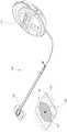
图1示出了负压治疗系统的实施例。Figure 1 shows an embodiment of a negative pressure therapy system.
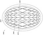
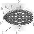
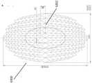
图2A-C示出了稳定结构的实施例的多个视图。2A-C illustrate various views of an embodiment of a stabilizing structure.
图3A-E示出了稳定结构和产生稳定结构的方法的另一实施例的多个视图。3A-E illustrate multiple views of another embodiment of a stabilized structure and method of producing the stabilized structure.
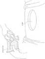
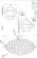
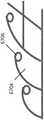
图4示出了可以围绕稳定结构的环的实施例。Figure 4 shows an embodiment of a ring that can surround a stabilizing structure.
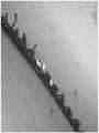
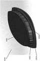
图5A-D是具有围绕的锚固件和泡沫层的稳定结构的实施例的照片。5A-D are photographs of an embodiment of a stabilizing structure with surrounding anchors and foam layers.
图6A-B是锚固层的实施例的照片。6A-B are photographs of examples of anchor layers.
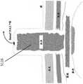
图7示出了开放性腹部伤口的实施例。Figure 7 shows an example of an open abdominal wound.
图8示出了治疗伤口的方法中的步骤的实施例。Figure 8 shows an example of steps in a method of treating a wound.
图9示出了治疗伤口的方法中的步骤的实施例。Figure 9 shows an example of steps in a method of treating a wound.
图10A-C示出了治疗伤口的方法的步骤的实施例。10A-C illustrate an embodiment of the steps of a method of treating a wound.
图11A-B是治疗伤口的方法的步骤的照片。11A-B are photographs of steps of a method of treating a wound.
图12A-C描绘了治疗伤口的方法的步骤的实施例。12A-C depict examples of steps of a method of treating a wound.
图13包含治疗伤口的方法的步骤的实施例的照片。Figure 13 contains photographs of examples of steps of a method of treating a wound.
图14A-G示出了治疗伤口的方法的实施例。14A-G illustrate an embodiment of a method of treating a wound.
图15A-E是治疗伤口的方法的实施例的照片。15A-E are photographs of examples of methods of treating wounds.
图16示出了稳定结构的实施例。Figure 16 shows an embodiment of a stabilizing structure.
图17A-E是稳定结构的实施例的附图和照片。17A-E are drawings and photographs of examples of stabilizing structures.
图18A-D示出了塌缩的稳定结构的实施例。18A-D illustrate an embodiment of a collapsed stabilization structure.
图19A-B示出了稳定结构的实施例。19A-B illustrate an embodiment of a stabilizing structure.
图20A-G示出了稳定结构和泡沫层的实施例。20A-G illustrate an embodiment of a stabilizing structure and foam layer.
图21示出了具有指状物的泡沫层的实施例。Figure 21 shows an embodiment of a foam layer with fingers.
图22A-E示出了具有印迹(printing)的泡沫层的实施例。22A-E illustrate an embodiment of a foam layer with printing.
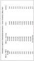
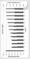
图23A-B呈现了使用稳定结构和伤口闭合设备的实施例收集的实验数据。Figures 23A-B present experimental data collected using examples of stabilizing structures and wound closure devices.
图24A-24C示出了稳定结构的实施例。24A-24C illustrate an embodiment of a stabilizing structure.
图25-27示出了稳定结构的不同实施例的放大视图。25-27 show enlarged views of various embodiments of stabilizing structures.
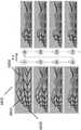
图28A-28E是承受负压的稳定结构的另一个实施例的照片。28A-28E are photographs of another embodiment of a stabilizing structure subjected to negative pressure.
图29示出了用于稳定结构的壁图案的另一实施例。Figure 29 shows another embodiment of a wall pattern for a stabilizing structure.
图30示出了利用稳定结构的实施例治疗伤口的方法的实施例。30 illustrates an embodiment of a method of treating a wound using an embodiment of a stabilizing structure.
具体实施方式Detailed ways
本部分或本说明书中其他部分公开的实施例涉及用减压治疗伤口的装置和方法,其包括泵和伤口敷料部件及装置。包括伤口覆盖和填充(packing)材料的这些装置和部件(如果有的话)有时在本部分或本说明书中其它地方统称为敷料。Embodiments disclosed in this section or elsewhere in this specification relate to devices and methods for treating wounds with reduced pressure, including pumps and wound dressing components and devices. These devices and components, if any, including wound covering and packing materials are sometimes collectively referred to in this section or elsewhere in this specification as dressings.
应理解,在整个说明书中都涉及伤口。应理解,术语伤口作广义地解释,并包括开放性的和闭合性的伤口,其中皮肤被撕裂、切割或刺破,或者外伤在此处导致患者皮肤上的挫伤、或任何其他表皮病症或其他病症或瑕疵,或者这些伤口受益于减压治疗。因此,伤口被广义地定义为可能产生液体或可能不产生液体的任何受损组织区域。这种伤口的示例包括,但不限于,腹部伤口或其他大伤口或切口性伤口,这些伤口或者是因手术、外伤、胸骨切开术、筋膜切开术导致的,或者是因其他病症、开裂性伤口、急性伤口、慢性伤口、亚急性和开裂性伤口、外伤性伤口、皮瓣和皮肤移植、撕裂伤、擦伤、挫伤、烧伤、电烧伤、糖尿病溃疡、压力性溃疡、造口、手术伤口、外伤和静脉溃疡等导致的。It should be understood that wounds are referred to throughout the specification. It should be understood that the term wound is to be interpreted broadly and includes both open and closed wounds where the skin is torn, cut or punctured, or where the trauma results in a bruise on the patient's skin, or any other epidermal disorder or Other conditions or blemishes, or these wounds benefit from reduced pressure treatment. Thus, a wound is broadly defined as any area of damaged tissue that may or may not produce fluid. Examples of such wounds include, but are not limited to, abdominal wounds or other large or incisional wounds, either as a result of surgery, trauma, sternotomy, fasciotomy, or other medical conditions, Dehiscent wounds, acute wounds, chronic wounds, subacute and dehiscing wounds, traumatic wounds, flaps and skin grafts, lacerations, abrasions, contusions, burns, electrical burns, diabetic ulcers, pressure ulcers, stoma , surgical wounds, trauma and venous ulcers.
如本部分或本说明书中其他部分所使用的,减压或负压水平,例如-XmmHg,表示低于标准大气压的压力水平,标准大气压对应于760mmHg(或1atm,29.93inHg,101.325kPa,14.696psi等)。因此,-XmmHg的负压值反映了比760mmHg低XmmHg的绝对压力,或者换句话说,反映了绝对压力为(760-X)mmHg。另外,比-XmmHg“更少”或“更小”的负压对应于更接近大气压的压力(例如,-40mmHg小于-60mmHg)。比-XmmHg“更多”或“更大”的负压对应于更偏离大气压的压力(例如,-80mmHg大于-60mmHg)。As used in this section or elsewhere in this specification, a reduced or negative pressure level, such as -XmmHg, means a pressure level below standard atmospheric pressure, which corresponds to 760 mmHg (or 1 atm, 29.93 inHg, 101.325 kPa, 14.696 psi Wait). Therefore, a negative pressure value of -XmmHg reflects an absolute pressure that is XmmHg lower than 760mmHg, or in other words, an absolute pressure of (760-X)mmHg. Additionally, a negative pressure that is "less" or "less" than -XmmHg corresponds to a pressure that is closer to atmospheric pressure (eg, -40mmHg is less than -60mmHg). A negative pressure that is "more" or "greater" than -XmmHg corresponds to a pressure that is further away from atmospheric pressure (eg, -80mmHg is greater than -60mmHg).
用于本公开的一些实施例的负压范围可为约-80mmHg,或在约-10mmHg和-200mmHg之间。注意,这些压力相对于正常环境大气压力。因此,-200mmHg实际上约为560mmHg。在一些实施例中,压力范围可以在约-40mmHg和-150mmHg之间。可替换地,可以使用高达-75mmHg、高达-80mmHg或者超过-80mmHg的压力范围。同样在其他实施例中可以使用低于-75mmHg的压力范围。可替换地,负压设备可以提供超过约-100mmHg或者甚至-150mmHg的压力范围。在一些实施例中,负压范围可以小至约-20mmHg或者约-25mmHg,这可有利于减少瘘管。在本文所述的伤口闭合设备的一些实施例中,伤口收缩增加可导致伤口周围组织中的组织扩张的增加。可以通过改变施加到组织的力来增加这种效果,例如通过随着时间改变施加到伤口的负压,可能与增加通过伤口闭合设备的实施例施加到伤口的拉力相结合。在一些实施例中,负压可以随着时间变化,例如通过使用正弦波、方波、和/或与一个或多个患者生理指标(例如,心跳)同步。The negative pressure range for some embodiments of the present disclosure may be about -80 mmHg, or between about -10 mmHg and -200 mmHg. Note that these pressures are relative to normal ambient atmospheric pressure. So -200mmHg is actually about 560mmHg. In some embodiments, the pressure range may be between about -40 mmHg and -150 mmHg. Alternatively, pressure ranges up to -75mmHg, up to -80mmHg, or in excess of -80mmHg may be used. Also in other embodiments pressure ranges below -75 mmHg may be used. Alternatively, the negative pressure device may provide a pressure range in excess of about -100mmHg or even -150mmHg. In some embodiments, the negative pressure range may be as small as about -20 mmHg or about -25 mmHg, which may be beneficial for reducing fistulas. In some embodiments of the wound closure devices described herein, increased wound contraction can result in increased tissue expansion in the tissue surrounding the wound. This effect can be increased by varying the force applied to the tissue, eg by varying the negative pressure applied to the wound over time, possibly in combination with increasing the tensile force applied to the wound by embodiments of the wound closure device. In some embodiments, the negative pressure may vary over time, eg, by using a sine wave, square wave, and/or synchronized with one or more patient physiological indicators (eg, heartbeat).
此类申请的示例包括如下美国专利:2012年8月7日授予的名称为“Woundtreatment apparatus and method”的美国专利No.8235955,以及2010年7月13日授予的名称为“Wound cleansing apparatus with stress”的美国专利No.7753894,在这些示例中可以找到与前述描述相关的额外公开。这两个申请都通过引用整体并入本文。其他申请可能包含相关的教导,这些教导用于与本部分或本说明书中其他部分描述的实施例一起使用,这些其他申请可包括如下申请:2010年9月20日提交的名称为“Systems And MethodsFor Using Negative Pressure Wound Therapy To Manage Open Abdominal Wounds”的申请序列号12/886088,其公开号为US2011/0213287;2011年4月21日提交的名称为“WoundDressing And Method Of Use”的申请序列号13/092042,其公开号为US2011/0282309;以及2012年2月3日提交的名称为“Negative Pressure Wound Closure Device”的申请序列号No.13/365615,其公开号为US2012/0209227,其中每一个申请的全部内容通过引用并入本文。还存在更多的申请可能包含用于与本说明书中描述的实施例一起使用的相关教导,这些更多的申请是如下的申请:2013年7月15日提交的名称为“Negative Pressure WoundClosure Device”的申请序列号13/942493,其公开号为US2014/0180225;2013年7月16日提交的名称为“Negative Pressure Wound Closure Device”的PCT申请No.PCT/US2013/050619,其公开号为WO2014/014871A1;2013年7月16日提交的名称为“Negative PressureWound Closure Device”的PCT申请No.PCT/US2013/050698,其公开号为WO2014/014922A1;2013年5月5日提交的名称为“Devices and Methods for Treating and Closing Woundwith Negative Pressure”的PCT申请No.PCT/IB2013/01555,其公开号为WO2013/175309A1;2014年3月12日提交的名称为“Negative Pressure Wound Closure Device andSystems and Methods of Use in Treating Wounds with Negative Pressure”的PCT申请No.PCT/US2014/025059,其公开号为WO2014/165275A1;2014年3月13日提交的名称为“CompressibleWound Fillers and Systems and Methods of Use in Treating Woundswith Negative Pressure”的PCT申请No.PCT/GB2014/050746,其公开号为WO2014/140578A1,以及2014年10月21日提交的“Negative Pressure Wound Closure Device”,其公开号为PCT/US2014/061627。上述申请中每一个的全部内容均通过引用并入本文,并且应视为本说明书的一部分。Examples of such applications include the following US Patents: US Patent No. 8,235,955, entitled "Woundtreatment apparatus and method," issued August 7, 2012, and "Wound cleansing apparatus with stress," issued July 13, 2010 ” of U.S. Patent No. 7,753,894, in which additional disclosure related to the foregoing description can be found in these examples. Both applications are incorporated herein by reference in their entirety. Other applications that may contain related teachings for use with the embodiments described in this section or elsewhere in this specification may include the following applications: Filed September 20, 2010 entitled "Systems And Methods For Using Negative Pressure Wound Therapy To Manage Open Abdominal Wounds" application serial number 12/886088, its publication number is US2011/0213287; application serial number 13/ filed on April 21, 2011 named "WoundDressing And Method Of Use" 092042, the publication number of which is US2011/0282309; and the application serial number No. 13/365615 of the title "Negative Pressure Wound Closure Device" filed on February 3, 2012, whose publication number is US2012/0209227, wherein each application The entire contents of are incorporated herein by reference. There are many more applications that may contain relevant teachings for use with the embodiments described in this specification, and these are the following applications: "Negative Pressure WoundClosure Device", filed July 15, 2013 The application serial number 13/942493, its publication number is US2014/0180225; the PCT application No.PCT/US2013/050619 named "Negative Pressure Wound Closure Device" submitted on July 16, 2013, its publication number is WO2014/ 014871A1; PCT application No. PCT/US2013/050698, filed on July 16, 2013, entitled "Negative PressureWound Closure Device", and its publication number is WO2014/014922A1; filed on May 5, 2013, entitled "Devices and Methods for Treating and Closing Wound with Negative Pressure" PCT Application No. PCT/IB2013/01555, its publication number is WO2013/175309A1; filed on March 12, 2014, entitled "Negative Pressure Wound Closure Device and Systems and Methods of Use in Treating Wounds with Negative Pressure" PCT Application No. PCT/US2014/025059, publication number WO2014/165275A1; filed March 13, 2014, entitled "Compressible Wound Fillers and Systems and Methods of Use in Treating Wounds with Negative Pressure" PCT application No. PCT/GB2014/050746, whose publication number is WO2014/140578A1, and "Negative Pressure Wound Closure Device" submitted on October 21, 2014, whose publication number is PCT/US2014/061627. The entire contents of each of the above applications are incorporated herein by reference and should be considered a part of this specification.
应当理解,在整个说明书中,在一些实施例中涉及一个或多个伸长的、细长的或纵向的条带。应当理解,这些术语将作广义地解释,并且在一些实施例中指的是具有两个平行或基本平行的面的细长材料,其中在横截面中,垂直于面所测量的材料的厚度相对小于平行于面测量的材料高度。虽然在一些实施例中,条带可以由离散长度的材料构造,但是在其他实施例中,条带可以简单地指代具有两个平行或基本平行的面的整体结构的细长部分。在一些实施例中,条带具有矩形或大致矩形的面,其中面的长度比面的高度长。在一些实施例中,面的长度可以比面的高度长不止2倍、4倍、6倍、8倍、10倍、12倍或更多。It should be understood that throughout the specification, one or more elongated, elongated or longitudinal strips are involved in some embodiments. It should be understood that these terms are to be construed broadly and in some embodiments refer to an elongated material having two parallel or substantially parallel faces, wherein in cross-section the thickness of the material measured perpendicular to the faces is relatively less than The height of the material measured parallel to the face. While in some embodiments the strips may be constructed of discrete lengths of material, in other embodiments the strips may simply refer to an elongated portion of a unitary structure having two parallel or substantially parallel faces. In some embodiments, the strip has a rectangular or substantially rectangular face, wherein the length of the face is longer than the height of the face. In some embodiments, the length of the facet may be more than 2 times, 4 times, 6 times, 8 times, 10 times, 12 times, or more longer than the height of the facet.
如在本部分或本说明书中其他部分所使用的,当涉及伤口时,术语“水平的”表示大致平行于伤口周围的皮肤的方向或平面。当涉及伤口时,术语“垂直的”通常是指垂直于水平平面延伸的方向。当涉及伤口时,术语“纵向的”通常是指在水平平面中沿着伤口最长的方向截取的方向。当涉及伤口时,术语“横向的”通常是指在水平平面中垂直于纵向方向的方向。术语“水平的”、“垂直的”、“纵向的”和“横向的”也可用于描述整个说明书中所述的稳定结构和伤口闭合设备。当描述这些结构或设备时,这些术语不应被解释为要求结构或设备必须以某个取向放置在伤口中,尽管在某些实施例中可以优选这样做。As used in this section or elsewhere in this specification, when referring to a wound, the term "horizontal" means a direction or plane that is generally parallel to the skin surrounding the wound. When referring to a wound, the term "vertical" generally refers to a direction extending perpendicular to a horizontal plane. When referring to a wound, the term "longitudinal" generally refers to the direction taken in the horizontal plane along the longest direction of the wound. When referring to a wound, the term "transverse" generally refers to a direction in a horizontal plane that is perpendicular to the longitudinal direction. The terms "horizontal", "vertical", "longitudinal" and "lateral" may also be used to describe the stabilizing structures and wound closure devices described throughout the specification. When describing these structures or devices, these terms should not be interpreted as requiring that the structures or devices must be placed in a wound in a certain orientation, although this may be preferred in certain embodiments.
图1示出了负压治疗系统100的实施例,其包括插入伤口101中的伤口填充件(packer)102。伤口填充件102可包括多孔材料,例如泡沫,并且在一些实施例中,可包括在本部分或本说明书中其他部分进一步详细描述的伤口闭合设备的一个或多个实施例。在一些实施例中,插入伤口101中的任何伤口闭合设备的周边或顶部也可以用泡沫或其他多孔材料覆盖。单个盖布104或多个盖布可以放置在伤口101上,并且优选地粘附或密封在伤口101的周边上的皮肤上,以便形成液密密封。孔106可以制作成穿过盖布104,孔106可以手动制作或预成形到盖布104中,以便提供从伤口101到负压源例如泵110的流体连接。优选地,孔106和泵110之间的流体连接经由导管108形成。在一些实施例中,导管108可包括由Smith&Nephew制造的
在一些实施例中,盖布104可设置有一个或多个波纹或褶皱。优选地,波纹沿着伤口的纵向轴线对准,并且因此可以通过优选地在垂直于伤口的纵向轴线的方向上塌缩来支撑伤口的闭合。这种波纹可有助于在伤口闭合的方向上平行于伤口表面施加收缩力。这种盖布的示例可以在2010年11月17日提交的名称为“Vacuum Closure Device”的申请序列号No.12/922118(其公开号为US2011/0054365)中找到,该申请通过引用整体并入本文。In some embodiments, the drape 104 may be provided with one or more corrugations or pleats. Preferably, the corrugations are aligned along the longitudinal axis of the wound and thus can support closure of the wound by collapsing preferably in a direction perpendicular to the longitudinal axis of the wound. Such corrugations may assist in applying contractile forces parallel to the wound surface in the direction of wound closure. An example of such a drape can be found in Application Serial No. 12/922118, filed November 17, 2010, entitled "Vacuum Closure Device" (whose publication number is US2011/0054365), which application is incorporated by reference in its entirety. into this article.
在使用中,准备并清洁伤口101。在一些情况下,例如腹部伤口的情况下,可以在任何暴露的内脏上施加非粘连或最小粘连的器官保护层(未示出)。接着将伤口填充件102插入伤口中,并用盖布104覆盖以形成液密的密封。然后将导管108的第一端放置成例如经由孔106与伤口流体连通。导管108的第二端连接到泵110。接着可以激活泵110,以便为伤口101提供负压,并抽净来自伤口101的伤口渗出物。如下文另外详细描述的,并且如与前述伤口闭合设备的实施例相关的描述,负压也可有助于促进伤口101的闭合,例如通过使相对的伤口边缘接近。In use, the wound 101 is prepared and cleaned. In some cases, such as in the case of abdominal wounds, a non-adhesive or minimally adhesive organ protector (not shown) may be applied over any exposed viscera. The wound filler 102 is then inserted into the wound and covered with a drape 104 to form a liquid tight seal. The first end of
本文本部分或者本说明书中其他部分公开的任何结构或部件可包括不透射线材料。不透射线材料有利地允许临床医生更容易地找到可能已与结构松脱并丢失在伤口中的伤口闭合设备的碎片。不透射线材料的一些示例包括硫酸钡、三氧化二铋、碱式碳酸铋、氯氧化铋和钨。Any structure or component disclosed in this section herein or elsewhere in this specification may include a radiopaque material. The radiopaque material advantageously allows the clinician to more easily locate fragments of the wound closure device that may have become loose from the structure and lost in the wound. Some examples of radiopaque materials include barium sulfate, bismuth trioxide, bismuth subcarbonate, bismuth oxychloride, and tungsten.
图2A-3E的稳定结构和伤口闭合设备Figures 2A-3E Stabilizing structure and wound closure device
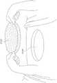
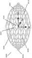
图2A是稳定结构6000的实施例的图,该稳定结构6000包括平行或半平行布置的多个细长条带6006,其纵向长度可与伤口的纵向轴线对准。在实施例中,细长条带6006也可以以非平行的方式布置。位于该稳定结构6000内的各种单元可具有各种形状和尺寸。如下文将更详细描述的,细长条带6006、中间构件6010和单元6004的长度和形状可以设计成促进稳定结构的更大闭合。在某些实施例中,细长条带和中间构件之间的接合部6900可以变薄,以更好地促进稳定结构的旋转和闭合。在一些实施例中,稳定结构是可撕裂的,使得该结构可以成形为伤口的形状。如说明书中其他部分所述,撕裂可以在中间构件和细长条带之间的交叉部处或者在沿着细长条带或中间构件的任何合适的位置处完成。Figure 2A is a diagram of an embodiment of a stabilizing
本文本部分或本说明书中其他部分描述的所有稳定结构可以制作成适应任何尺寸的伤口。但是,为了更好地适应临床环境的需要,在某些实施例中,本文所述的稳定结构可以以两种尺寸的包装提供,一种较小的稳定结构和一种较大的稳定结构,该较大的稳定结构约为1.25倍大,约为1.5倍大,约为1.75倍大,约为2倍大,约为2.5倍大,约为3倍大,约为4倍大,约为5倍大,或大于约5倍大。在一些实施例中,包装可包括多于两种尺寸,例如三种尺寸、四种尺寸、五种尺寸或多于五种尺寸。包装内的稳定结构可以具有相对于彼此的各种尺寸,例如上述比例。All of the stabilizing structures described in this section or elsewhere in this specification can be made to accommodate wounds of any size. However, to better suit the needs of a clinical setting, in certain embodiments, the stabilizing structures described herein may be provided in two sized packages, a smaller stabilizing structure and a larger stabilizing structure, The larger stable structure is about 1.25 times larger, about 1.5 times larger, about 1.75 times larger, about 2 times larger, about 2.5 times larger, about 3 times larger, about 4 times larger, about 5 times larger, or greater than about 5 times larger. In some embodiments, the package may include more than two sizes, eg, three sizes, four sizes, five sizes, or more than five sizes. The stabilizing structures within the package may have various dimensions relative to each other, such as the ratios described above.
在某些实施例中,稳定结构6000可在施加负压或者不施加负压的情况下,以本部分或本说明书中其他部分描述的任何方式塌缩。例如,当施加负压时,稳定结构在一个平面中比在另一个平面中明显更多地塌缩。在一些实施例中,稳定结构构造成在平行于稳定结构的长度和宽度的水平平面中比在垂直于该水平平面的垂直平面中更多地塌缩。在实施例中,特定行可以在第一方向上塌缩,而另一行可以在相同或相反的方向上塌缩。在某些实施例中,稳定结构可以沿着稳定结构的宽度塌缩,同时在垂直方向上以及沿着稳定结构的长度保持相对的刚性。In certain embodiments, the stabilizing
稳定结构可以由本部分或本说明书中其他部分描述的任何材料构成,包括:柔性塑料,例如硅树脂、聚氨酯,硬质塑料,例如聚氯乙烯,半硬质塑料,半柔性塑料,生物相容性材料,复合材料,金属和泡沫。在某些实施例中,稳定结构可包括不透射线材料,以便更容易地允许临床医生在伤口内找到稳定结构的碎片。The stabilizing structure may be constructed of any of the materials described in this section or elsewhere in this specification, including: flexible plastics such as silicone, polyurethane, rigid plastics such as polyvinyl chloride, semi-rigid plastics, semi-flexible plastics, biocompatible Materials, composites, metals and foams. In certain embodiments, the stabilizing structure may comprise a radiopaque material to more easily allow the clinician to locate fragments of the stabilizing structure within the wound.
返回图2A,稳定结构6000可具有限定至少部分椭圆形状的外周边。如上所述,稳定结构6000可包括并排设置的多个单元6004,每个单元由一个或多个壁限定,每个单元具有顶端和底端,且具有延伸穿过顶端和底端的开口。与本文本部分和本说明书中其他部分描述的其他稳定结构一样,稳定结构6000构造成通过使一个或多个单元6004塌缩而塌缩。在一些实施例中,所有的单元具有相同的近似形状和尺寸;但是,在其他实施例中,单元具有不同的形状和尺寸。在一些实施例中,如本文本部分或本说明书中其他部分描述的稳定结构可以是圆顶形(domed)的,使得稳定结构的中心部分向上凸出。例如,稳定结构的下部可以是凹形的,而稳定结构的上部是凸形的。Returning to Figure 2A, the
细长条带6006可以由单一材料制成,例如本说明书中其他部分描述的那些材料,或者细长条带可以由多种材料制成。例如,细长条带6006可包括由较刚性材料制成的部分和由较柔性材料制成的部分。细长条带6006可沿其长度弯曲,以促进稳定结构6000的弯曲的外周边。细长条带可沿其长度向外弯曲而远离稳定结构6000的中心。细长条带6006的曲线弧度可以显著变化,其中一些条带6006高度弯曲,而另一些条带最小程度地弯曲或者甚至是直的。The
类似地,稳定结构6000可进一步包括连接到细长条带6006的多个中间构件6010。所有的中间构件6010可具有相似的形状和尺寸,或者它们可具有各种形状和尺寸。中间构件可以由本文本部分或说明书中其他部分公开的任何材料构造。此外,中间构件可以由多种材料构造。Similarly, the
有利地,稳定结构6000的椭圆形状可以允许该结构更好地适应伤口的形状。大多数伤口是圆化的,因此,椭圆形的稳定结构6000可以更好地适合伤口。Advantageously, the oval shape of the stabilizing
在实施例中,外周边6002可具有减少(reduced)的边缘6012,以促进稳定结构的塌缩。通过在减少的边缘6012处移除稳定结构的质量(mass),稳定结构可以在减少的边缘6012处更自由地塌缩,从而允许更好地配合在伤口内。此外,通过降低在减少的边缘6012处的质量,在稳定结构6000塌缩期间和之后,周围组织的挤压(pinching)可能较少。In an embodiment, the
本部分或本说明书中其他部分描述的稳定结构6000以及所有的稳定结构和伤口闭合设备可以动态的方式按各种时间表(timescales)塌缩。在某些实施例中,大部分塌缩可在负压施加后的最初几分钟内发生。但是,在初始塌缩之后,稳定结构或伤口闭合设备可以以慢得多的速度继续塌缩,从而在长时间段内施加增加的纵向张力,并且拉动伤口边缘更靠近在一起。通过随着时间缓慢地拉动伤口边缘更靠近在一起,稳定结构或伤口闭合设备允许周围正在愈合的组织与设备或稳定结构的闭合协同地重塑。缓慢、动态的伤口闭合可允许周围组织以加快的速度愈合,因为正在塌缩的结构或设备缓慢地使伤口边缘更靠近在一起,而不会太快地对新形成的或变弱的组织施加压力。The stabilizing
在一些实施例中,本部分或本说明书中其他部分描述的稳定结构可以放置在伤口中一段时间,然后移除,或者用另一个稳定结构替代。例如,稳定结构可以插入到伤口中一段时间,通过拉动边缘更靠近在一起来促进伤口的闭合。经过一段时间后,稳定结构可以被具有不同尺寸或塌缩性能的稳定结构替代,例如较小尺寸或密度降低的稳定结构。该过程可以反复重复,从而随着时间持续地将伤口边缘拉到一起,并允许周围组织的持续修复和重塑。在某些实施例中,稳定结构构造成在伤口中保持至少约少于1小时,至少约1小时,至少约2小时,至少约4小时,至少约6小时,至少约8小时,至少约12小时,至少约24小时,至少约2天,至少约4天,至少约6天,至少约1周,至少约2周,至少约3周,或超过3周。In some embodiments, the stabilizing structures described in this section or elsewhere in this specification can be placed in the wound for a period of time and then removed, or replaced with another stabilizing structure. For example, a stabilizing structure can be inserted into the wound for a period of time to facilitate closure of the wound by pulling the edges closer together. After a period of time, the stabilizing structure can be replaced by a stabilizing structure having a different size or collapsing property, such as a smaller size or reduced density stabilizing structure. This process can be repeated over and over, continuously pulling the wound edges together over time and allowing for continued repair and remodeling of the surrounding tissue. In certain embodiments, the stabilizing structure is configured to remain in the wound for at least about less than 1 hour, at least about 1 hour, at least about 2 hours, at least about 4 hours, at least about 6 hours, at least about 8 hours, at least about 12 hours hours, at least about 24 hours, at least about 2 days, at least about 4 days, at least about 6 days, at least about 1 week, at least about 2 weeks, at least about 3 weeks, or more than 3 weeks.
在某些实施例中,稳定结构或伤口闭合设备的高达90%的塌缩可在负压施加后的最初几分钟内发生,而剩余的10%的塌缩可在许多分钟、许多小时、许多天、许多周或许多月的时间段内缓慢地发生。在其他实施例中,高达约80%的塌缩,高达约70%、高达约60%、高达约50%、高达约40%、高达约30%、高达约20%、高达约10%或约0%的塌缩在负压施加后的最初几分钟内将立即发生,而其余的塌缩以慢得多的速度发生,例如在许多分钟、许多小时、许多天、许多周或许多月的过程中发生。在其他实施例中,稳定结构可以以可变速度塌缩。在一些实施例中,整个塌缩以减慢的速度发生,而在其他实施例中,整个塌缩几乎立即在最初的几分钟内发生。在进一步的实施例中,塌缩可以以任何速度发生,并且速度可以随时间变化。在某些实施例中,通过添加和/或移除部分结构,或者通过控制负压和冲洗液(irrigant fluid)的施加,可以以可变的方式改变塌缩的速度。In certain embodiments, up to 90% of the collapse of the stabilizing structure or wound closure device can occur within the first few minutes after negative pressure is applied, while the remaining 10% of collapse can occur within many minutes, many hours, many Occurs slowly over a period of days, weeks, or months. In other embodiments, up to about 80% collapse, up to about 70%, up to about 60%, up to about 50%, up to about 40%, up to about 30%, up to about 20%, up to about 10%, or about 0% of the collapse will occur immediately within the first few minutes after the negative pressure is applied, while the rest of the collapse will occur at a much slower rate, such as over the course of many minutes, hours, days, weeks, or months occur in. In other embodiments, the stabilizing structure may collapse at a variable rate. In some embodiments, the entire collapse occurs at a reduced rate, while in other embodiments, the entire collapse occurs within the first few minutes almost immediately. In further embodiments, the collapse can occur at any speed, and the speed can vary over time. In certain embodiments, the rate of collapse can be varied in a variable manner by adding and/or removing parts of the structure, or by controlling the application of negative pressure and irrigation fluid.
返回图2A,在一些实施例中,稳定结构6000的图案以这样的方式设计,以促进稳定结构的最大程度闭合。优选地,最大程度闭合在垂直于细长构件的长度的方向上,并且在水平平面内。如下文将更详细描述的,通过改变细长条带6006的长度、中间构件6010的长度以及单元6004的形状可以实现更大的闭合。单元6004的形状可以包括本文本部分或说明书中其他部分描述的任何形状。例如,如图2A所示,单元6004可以是菱形或平行六面体,其中较小的类菱形(diamond-like)形状6020位于较大的菱形6022内。这种结构可以提供稳定设备6000的更大的整体闭合,以提供伤口的最大程度闭合。另外,位于较大的菱形6022内的较小的类菱形形状6020可以将载荷分布在更大的区域上,从而减少对基质(matrix)下方的组织结构造成损伤的机会。这种结构还可以降低泡沫或盖布被拉入基质中并阻止伤口闭合的可能性。Returning to Figure 2A, in some embodiments, the pattern of the stabilizing
图2B-C是图2A的稳定结构实施例的不同视图的图示。如上面关于图2A的描述,稳定结构包括单元6004、中间构件6010和细长条6006;但是,在此还包括伤口6910的模拟形状,以用于比较。2B-C are illustrations of different views of the stabilization structure embodiment of FIG. 2A. As described above with respect to Figure 2A, the stabilizing structure includes
本文本部分或本说明书中其他部分描述的任何稳定结构可以由任何合适的方式构造。例如,稳定结构可以通过模制来构造,或者可以使用3D打印技术直接打印。在某些实施例中,图2A-C的稳定结构可以通过3D打印由单一聚合物来构造。在一些实施例中,稳定结构可以由一种聚合物、两种聚合物、三种聚合物或多于三种的聚合物来构造。稳定结构可以由本文本部分或本说明书中其他部分公开的任何材料构造。稳定结构可以通过从固体材料块切割出该结构来制造。用于切割的方法可包括例如水射流切割、激光切割或模切。可以沿着单元6004的壁将稳定结构切割成一定尺寸。例如,可以切除沿着细长条6006的外表面的中间构件,以适当地确定稳定结构的尺寸。可以沿着壁、沿着细长条带的任何部分、和/或沿着中间构件的任何部分切割稳定结构。Any of the stabilizing structures described in this section herein or elsewhere in this specification may be constructed in any suitable manner. For example, stable structures can be constructed by molding, or can be directly printed using 3D printing technology. In certain embodiments, the stable structures of Figures 2A-C can be constructed from a single polymer by 3D printing. In some embodiments, the stabilizing structure may be constructed from one polymer, two polymers, three polymers, or more than three polymers. The stabilizing structure may be constructed of any of the materials disclosed in this section or elsewhere in this specification. A stable structure can be fabricated by cutting the structure out of a block of solid material. Methods for cutting may include, for example, water jet cutting, laser cutting or die cutting. The stabilizing structure can be cut to size along the walls of the
在一些实施例中,图2A-C的稳定结构6000可以构造成包括穿孔或可拆卸部分,其允许设备的部分与设备的其余部分分离。例如,穿孔可以结合到包含在稳定结构6000内的各种单元6004之间的接合部(joint)6900中,从而允许移除单个行或单元,以改变稳定结构6000的形状。In some embodiments, the
适用于本部分或说明书中其他部分描述的所有稳定结构或伤口闭合设备,稳定结构或伤口闭合设备可以是可撕裂的,使得稳定结构可以成形为伤口的形状。在一些实施例中,稳定结构可以在中间构件和细长条带之间的交叉部处被撕裂,而在进一步的实施例中,细长条带或中间构件可以在任何合适的位置处被撕裂。Applicable to all stabilizing structures or wound closure devices described in this section or elsewhere in the specification, the stabilizing structure or wound closure device may be tearable so that the stabilizing structure may be shaped into the shape of the wound. In some embodiments, the stabilizing structure may be torn at the intersection between the intermediate member and the elongated strip, while in further embodiments, the elongated strip or intermediate member may be torn at any suitable location torn.
图3A-E描绘了用于生成稳定结构的设计的方法,例如图2A-C的稳定结构。为了促进各种类型的闭合(例如,最大程度闭合),可以通过各种方法确定细长条带、中间构件和单元的形状、尺寸和位置。例如,如图3A所示,每个可塌缩单元6030具有四个侧面,并且中间构件和/或细长条带之间的每个交叉部可以通过销联接6032建模。此外,整个稳定结构6034可以在椭圆形伤口模型6036内建模。如图3A所示,稳定结构6034可以如此建模,以从开放状态6038塌缩到半塌缩状态6040,再到完全塌缩状态6042。在一些临床情况下,可能期望最大限度地闭合到完全扁平的稳定结构,以通过拉动伤口边缘尽可能靠近在一起来最大化伤口闭合。Figures 3A-E depict methods for generating designs of stable structures, such as the stable structures of Figures 2A-C. To facilitate various types of closure (eg, maximal closure), the shape, size and location of the elongated strips, intermediate members and elements may be determined by various methods. For example, as shown in FIG. 3A , each
如图3B所示,在某些实施例中,可以通过将稳定结构建模为位于镜像线6050(其也可称为横向轴线,垂直于稳定结构的纵向轴线)的相对侧上的镜像图案来促进确定用于伤口闭合的细长条带、中间构件和单元的最佳形状、尺寸和位置的过程,从而使稳定结构的弯曲和塌缩对称。镜像轴线可以沿着稳定结构的短轴,或者可以沿着稳定结构的长轴。可替换地,镜像线可位于稳定结构内的任何合适位置,例如对角地穿过稳定结构。在某些实施例中,该方法可以在中心线附近导致大的菱形单元。这些大的菱形结构6052可以进一步细分,以通过在较大形状内包括较小的菱形6054来进一步支撑稳定结构。在一些实施例中,较大形状6052内的这些较小形状6054可包括本文本部分或本说明书中其他部分公开的任何形状。较大的单元可以进一步细分为两个较小的形状、三个较小的形状、四个较小的形状或者多于四个的较小形状。本领域技术人员将理解,镜像线不必局限于垂直于伤口的纵向取向的线。相反,镜像线可以布置成沿着伤口的纵向轴线,或者与伤口的纵向轴线成一角度。在一些实施例中,稳定结构可包含多个镜像线,从而具有对称或不同的多个子部分。As shown in Figure 3B, in some embodiments, the stabilization structure can be modeled as a mirror image pattern on opposite sides of the mirror line 6050 (which may also be referred to as the transverse axis, perpendicular to the longitudinal axis of the stabilization structure) Facilitates the process of determining the optimal shape, size, and location of the elongated strips, intermediate members, and units for wound closure so that bending and collapse of the stabilizing structure is symmetrical. The mirror axis can be along the short axis of the stabilizing structure, or it can be along the long axis of the stabilizing structure. Alternatively, the mirror line may be located at any suitable location within the stabilizing structure, such as diagonally across the stabilizing structure. In some embodiments, the method may result in large diamond-shaped cells near the centerline. These large diamond-shaped
如图3C所示,对于待塌缩的四边形单元,它必须遵循简单的公式:a+b=c+d,其中a、b、c和d是稳定结构内的单个单元的各个边的长度,例如图3C的单元6060。当构件c和b一起塌缩时,接着d和a一起塌缩。该公式可以是研发使塌缩性能最大化的稳定结构的图案的基础。As shown in Figure 3C, for a quadrilateral element to be collapsed, it must follow a simple formula: a+b=c+d, where a, b, c, and d are the lengths of the individual sides of a single element within the stable structure, For example,
图3D示出了图3C中描述的概念的扩展。通过使用基础公式a+b=c+d,细长条带朝向水平镜像线6050渐进地加长(a4>a3>a2>al),从而实现稳定结构中的曲线(curve),同时防止任何中间构件6062变得垂直于细长条带6064(即具有90度的内角)。如图3D所示,可以选择bl的值,此时还可以选择任意偏移值x,以便于各种单元几何形状的构造。使用图3D6066中可视地示出的a1到a4的渐进值,可以计算出6068中示出的bl-b4的值。使用从方程式6068导出的用于各个单元的各种壁的计算值允许完全塌缩的稳定结构的设计,例如图3A-B中所示的那些。Figure 3D shows an extension of the concept described in Figure 3C. By using the underlying formula a+b=c+d, the elongated strip lengthens progressively towards the horizontal mirror line 6050 (a4>a3>a2>al), thereby achieving a curve in a stable structure while preventing any
在一些实施例中,用于生成稳定结构设计的方法可以包括加速初始几何结构的构造的步骤。例如,如果在特定行中从左到右的所有构件,如图3E中的中间构件6036所示,则出现交替的垂直构件也是相同长度的图案。相同长度的壁由它们各自的附图标记6070、6072、6074和6076表示。一旦初始设计生成,则可以通过根据图3D公式的加长、缩短、移除或插入来修改各个单元,以实现期望的稳定结构的整体形状。In some embodiments, a method for generating a stable structural design may include the step of accelerating the construction of an initial geometry. For example, if all the members in a particular row are from left to right, as shown by the
图4-6B的锚固层Anchor layer of Figure 4-6B
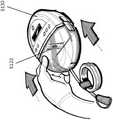
图4示出了锚固层4800的实施例,该锚固层4800可以围绕如本部分或本说明书中其他部分所述的稳定结构。环4800可包括一层组织锚固件4802,其构造成抓住(grip)伤口的周围边缘。例如,组织锚固件可以是钩、倒钩、尖头(prong)或用于附接到伤口组织的其他结构。在某些实施例中,组织锚固件包括钩环紧固件,例如Velcro技术中使用的那些。在某些实施例中,环4800可以由泡沫构成,例如前文描述的那些,或者环可以由泡沫层和组织锚固层4802的组合构成。唇缘4804可以从环4800向内延伸,并用于与如本部分或本说明书中其他部分所述的稳定结构的顶部和/或底部重叠,从而将环4800固定在稳定结构周围。FIG. 4 illustrates an embodiment of an
图5A-D是根据另一实施例的伤口闭合设备5000的照片。伤口闭合设备5000包括稳定结构5002,其可以类似于图2A-3E中描述的结构,或者可以包括本说明书中其它部分描述的任何稳定结构。稳定结构5002可以可选地被多孔层5004(例如泡沫层)围绕,并且多孔层可被锚固层5006围绕,锚固层5006包括组织锚固件(例如由Velcro工业生产的那些锚固件)、各种倒钩和/或各种钩。在某些实施例中,多孔层可以是带状的形式。稳定结构5002、多孔层5004和锚固层5006可以作为单独的部件提供,以由从业者在使用中附接,或者它们可以彼此预先附接。5A-D are photographs of a
类似于图2A-3E中所示的实施例,稳定结构5002可以以本说明书中其他部分描述的任何方式塌缩,例如,水平地塌缩。当植入伤口闭合设备5000时,可以使周围组织压靠组织锚固件,以将它们嵌入组织内,并锚固该设备。在一些实施例中,伤口闭合设备5000可以放置在伤口中,并用盖布密封。尽管本部分进一步描述的实施例包括围绕多孔层的锚固层,但是其他实施例可以省略多孔层,使得锚固层直接围绕稳定结构或者附接到稳定结构。Similar to the embodiment shown in Figures 2A-3E, the stabilizing
在一些实施例中,锚固层5006包括细长条带材料,该细长条带材料包括从基底层5007延伸的多个组织锚固件,其中组织锚固件可具有如说明书中其他部分所述的不同的形状和尺寸。组织锚固件可以从细长条带的第一平面侧延伸,并且细长条带的第二平面侧可以包括由粘性背衬层覆盖的粘合剂。锚固件的结构可以具有各种形式,这取决于它们要结合的组织。较长的锚固件可用于松散结合的组织,例如脂肪或结缔组织,而较短的锚固件可用于更致密的组织,例如肌肉。在其他实施例中,取决于锚固件的形状,较短的锚固件可能更期望用于较软的脂肪组织,而较长的锚固件用于更致密的组织。具有更刚性的柄(stem)的锚固件可用于穿透更致密的组织。在一些实施例中,锚固件可以具有双侧尖头(prong),该双侧尖头在插入组织中时倾向于塌缩,但是在沿相反方向被拉动时趋向于膨胀,使得可以向组织施加一定的拉力。锚固件或附接机构的特征以及它们的合力曲线可以根据许多参数而变化,例如锚固件的长度,附接机构的形状,抓握特征部的结构,用于附接机构的材料,附接机构的相对柔性/刚性,以及附接机构的间距/密度。In some embodiments, the
锚固件可具有各种长度,以便最佳地穿透周围组织。例如,锚固件的长度可以是至多约0.01mm,至多约0.1mm,至多约0.2mm,至多约0.5mm,至多约1mm,至多约2mm,至多约3mm,至多约5mm,至多约10mm,至多约20mm,至多约30mm,至多约40mm,至多约50mm,至多约75mm,至多约100mm,或大于100mm。Anchors can be of various lengths for optimal penetration of surrounding tissue. For example, the length of the anchor may be at most about 0.01 mm, at most about 0.1 mm, at most about 0.2 mm, at most about 0.5 mm, at most about 1 mm, at most about 2 mm, at most about 3 mm, at most about 5 mm, at most about 10 mm, at most about 20mm, up to about 30mm, up to about 40mm, up to about 50mm, up to about 75mm, up to about 100mm, or greater than 100mm.
图5B是图5A中描绘的伤口闭合设备5002的锚固层5006的更近距离视图的照片。锚固层可以包括由较长的锚固件构成的第一带5008和由较短的锚固件构成的第二带5010,第一带5008构造成围绕多孔层5004和稳定结构5002,第二带5010构造成围绕多孔层5004和稳定结构5002。如图所示,第一带5008可以设置在第二带5010的上方。在一些实施例中,可以存在另外的交替的一系列带,它们相对于彼此垂直。在进一步的实施例中,如本文本部分和说明书中其他部分所公开的,不同的带可以具有不同的锚固件长度和形状。例如,取代具有2种类型的锚固件的2种类型的带,可以存在具有3种类型的锚固件的3种类型的带,或者具有4种类型的锚固件的4种类型的带等。优选地,选择锚固件以用于适当的组织类型。例如,返回到图5B,第一带5008可以包括较长的锚固件,其期望用于穿透到更致密的筋膜中,因此可以朝向设备的底部定位。类似地,第二带5010包括较短的双钩,其期望用于穿透到更致密的组织。如本说明书中其他部分所述,其他合适的组织锚固件包括Velcro的钩环构造、倒钩、钩、长钉(spike)、钉(peg)、箭头状物或任何合适的形状。表面的进一步示例包括纹理表面,例如粗糙的砂纸状表面,或者可以促进组织粘连的纳米纹理表面。Figure 5B is a photograph of a closer view of the
在一些实施例中,表面锚固件的使用可以与外科粘合剂组合使用,从而在组织层之间提供比单独使用粘合剂强得多的粘合,并在粘合剂凝固时提供临时粘连。在一些实施例中,外科粘合剂可以添加到锚固件本身。在某些实施例中,外科粘合剂可以简单地施加在锚固件之间,以涂覆锚固层的至少一部分。在进一步的实施例中,锚固件可以用外科粘合剂替代,并且外科粘合剂可以用于将设备锚固到周围的伤口。In some embodiments, the use of surface anchors can be used in combination with surgical adhesives to provide a much stronger bond between tissue layers than the adhesive alone, and to provide temporary adhesion as the adhesive sets . In some embodiments, surgical adhesive may be added to the anchor itself. In certain embodiments, a surgical adhesive may simply be applied between the anchors to coat at least a portion of the anchor layer. In further embodiments, the anchor can be replaced with a surgical adhesive, and the surgical adhesive can be used to anchor the device to the surrounding wound.
在某些实施例中,锚固件可以由各种材料构造,包括说明书中其他部分公开的任何材料,例如:合成或天然聚合物,金属,陶瓷或其他合适的材料。锚固件可以由可生物降解的材料构造,例如可生物降解的合成或天然聚合物。可生物降解的合成聚合物的非限制性示例包括:聚酯(例如聚乳酸或聚乙醇酸),聚酸酐和具有可生物降解的链的线性聚合物。此外,锚固件可以由可生物降解的生物材料构造,例如自体移植物,同种异体移植物和/或异种移植物。In certain embodiments, the anchors may be constructed from a variety of materials, including any of the materials disclosed elsewhere in the specification, such as: synthetic or natural polymers, metals, ceramics, or other suitable materials. Anchors can be constructed from biodegradable materials, such as biodegradable synthetic or natural polymers. Non-limiting examples of biodegradable synthetic polymers include: polyesters (eg, polylactic acid or polyglycolic acid), polyanhydrides, and linear polymers with biodegradable chains. Additionally, the anchors can be constructed from biodegradable biomaterials, such as autografts, allografts and/or xenografts.
图5C是伤口闭合设备5000的实施例的照片,其类似于图5A-B的伤口闭合设备。但是,在该取向中,锚固件的第一带5008朝向设备的底部,而锚固件的第二带5010朝向顶部。如上所述,锚固件的带可以以任何期望的方式排列。图5D是伤口闭合设备5000的实施例的俯视图,其类似于图5A-C的伤口闭合设备。Figure 5C is a photograph of an embodiment of a
考虑到图5A-D的锚固层,锚固层的形状不限于图4的环形。在一些实施例中,锚固层缠绕在整个稳定设备周围,即顶部,底部和侧面。在其他实施例中,锚固层仅在稳定结构的一部分周边的周围。在某些实施例中,根据需要,锚固层仅附接到稳定结构的离散的部分。在一些实施例中,锚固层覆盖稳定结构的外部的至多约5%,至多约10%,至多约20%,至多约30%,至多约50%,至多约75%,和至多约100%。Considering the anchoring layers of FIGS. 5A-D, the shape of the anchoring layers is not limited to the annular shape of FIG. 4 . In some embodiments, the anchoring layer wraps around the entire stabilizing device, ie the top, bottom and sides. In other embodiments, the anchoring layer is only around a portion of the perimeter of the stabilizing structure. In certain embodiments, the anchoring layer is attached to only discrete portions of the stabilizing structure, as desired. In some embodiments, the anchor layer covers at most about 5%, at most about 10%, at most about 20%, at most about 30%, at most about 50%, at most about 75%, and at most about 100% of the exterior of the stabilizing structure.
在一些实施例中,不同组织锚固件构成的带可以安排在垂直方向上,而在其他实施例中,它们可以安排在水平方向上。当在xy平面中考虑时,它们也可以安排在水平和垂直方向上,即面向下进入伤口。In some embodiments, bands of different tissue anchors may be arranged in a vertical direction, while in other embodiments they may be arranged in a horizontal direction. When considered in the xy plane, they can also be arranged horizontally and vertically, ie face down into the wound.
在某些实施例中,不同类型的锚固件可以彼此夹杂,而不是安排成由特定类型的锚固件构成的离散的带。例如,较长的锚固件可以被较小的锚固件围绕,反之亦然。在一些实施例中,锚固件可以在锚固层上随机安排,或者以其他合适的图案安排。In some embodiments, different types of anchors may be interspersed with each other, rather than arranged as discrete bands of particular types of anchors. For example, longer anchors can be surrounded by smaller anchors and vice versa. In some embodiments, the anchors may be randomly arranged on the anchoring layer, or arranged in other suitable patterns.
在特定实施例中,锚固层可设置在稳定结构的内表面上。例如,锚固层可以覆盖稳定结构的内表面的至多约5%,至多约10%,至多约20%,至多约30%,至多约50%,至多约75%,并且至多约100%。In certain embodiments, the anchoring layer may be disposed on the inner surface of the stabilizing structure. For example, the anchor layer may cover up to about 5%, up to about 10%, up to about 20%, up to about 30%, up to about 50%, up to about 75%, and up to about 100% of the inner surface of the stabilizing structure.
在进一步的实施例中,整个锚固层可以仅由一种类型的锚固件构成,例如,整个锚固层可以由如图5B所示的较长钩5008或较短钩5010构成。一些实施例可以要求对锚固件进行颜色编码。例如,底部上的锚固件可以制成一种颜色,而顶部上的锚固件可以是另一种颜色,以便识别稳定结构在伤口中的正确取向。In further embodiments, the entire anchoring layer may be composed of only one type of anchor, eg, the entire anchoring layer may be composed of
图6A-B是具有锚固件12008的锚固层12000的实施例的图片,锚固件12008类似于图5A-D中所示的锚固件。这种锚固件的示例可以从Alfatex获得。在一个实施例中,锚固层可以设置成包括3D织物材料或其一部分。例如,3D织物可包括机织物(woven fabric)层和多根单丝,该机织织物层沿第一平面设置,该多根单丝从机织织物层垂直延伸,或者相对于机织织物层成一定角度地延伸。机织织物层可构造成直接或间接地附接到稳定结构的外部,该稳定结构如本说明书中其它部分所述,并且如通过引用并入的申请所述。单丝可具有蘑菇形的头部,或者具有构造成接合围绕稳定结构的组织的其他形状。单丝的头部可类似于锤顶(peened)铆钉,该铆钉具有扁平头部和接合周围组织的延伸边缘。如果单丝以一定角度突出,则材料在剪应力(shear)的一个方向上比另一个方向上产生更多的抓力(grip)。这种方向性意味着锚固层和单丝可以定位在稳定结构上,使得剪应力用于阻止设备被内脏推动向上或者离开伤口,但是锚固层和单丝可以通过将它向下推动而容易地释放。6A-B are pictures of an embodiment of an
图7-15E的伤口闭合和治疗方法Figures 7-15E Wound Closure and Treatment Methods
本部分或本说明书中其他部分描述的稳定结构和/或伤口闭合设备可以与用于伤口闭合的方法或系统结合使用。在用于伤口闭合的方法的一些实施例中,本部分或本说明书中其它部分描述的任何实施例的一个或多个稳定结构或伤口闭合设备放置到伤口中。在一些实施例中,器官保护层可以在放置稳定结构之前设置在伤口中。在某些实施例中,泡沫或其他多孔材料可以与稳定结构或伤口闭合设备一起放置在伤口中,或者以在稳定结构或伤口闭合设备的下方、上方或周围的方式放置在伤口中。泡沫或其他多孔材料也可围绕稳定结构或伤口闭合设备的周边。稳定结构或伤口闭合设备可构造成以本部分或本说明书中其他部分描述的任何方式塌缩,例如,通过具有特定的尺寸和形状,或者通过包括位于结构的单元内的一定体积的泡沫或其它多孔材料。稳定结构或伤口闭合设备可进一步以本部分或本说明书中其他部分描述的任何方式改变,以便更好地适应伤口的形状。在放入伤口后,稳定结构或伤口闭合设备可以由液密的盖布密封。液密的盖布可包括构造用于施加负压的端口。然后负压源可以连接到端口,并且负压可以施加到伤口上。稳定结构或伤口闭合设备可随着时间被具有期望的各种形状和尺寸的稳定结构或伤口闭合设备更换,以最佳地促进伤口愈合。The stabilizing structures and/or wound closure devices described in this section or elsewhere in this specification may be used in conjunction with a method or system for wound closure. In some embodiments of the method for wound closure, one or more stabilizing structures or wound closure devices of any of the embodiments described in this section or elsewhere in this specification are placed into the wound. In some embodiments, the organ protective layer may be placed in the wound prior to placement of the stabilizing structure. In certain embodiments, the foam or other porous material may be placed in the wound with the stabilizing structure or wound closure device, or placed in the wound under, over, or around the stabilizing structure or wound closure device. Foam or other porous materials may also surround the perimeter of the stabilization structure or wound closure device. A stabilizing structure or wound closure device may be configured to collapse in any manner described in this section or elsewhere in this specification, for example, by having a specific size and shape, or by including a volume of foam or other Porous material. The stabilizing structure or wound closure device may be further modified in any of the ways described in this section or elsewhere in this specification to better accommodate the shape of the wound. After placement in the wound, the stabilizing structure or wound closure device can be sealed with a liquid-tight drape. The liquid-tight drape may include ports configured for applying negative pressure. A source of negative pressure can then be connected to the port, and negative pressure can be applied to the wound. The stabilizing structure or wound closure device may be replaced over time with stabilizing structures or wound closure devices of various shapes and sizes as desired to optimally promote wound healing.
图7-15E是描绘利用伤口闭合设备治疗伤口的方法的实施例的照片和图示,该伤口闭合设备包括如本文本部分和本说明书中其他部分所述的稳定结构。为了更好地说明方法的非限制性实施例,图13的步骤已添加了数字,以允许读者更容易地遵循该方法的这些步骤。然而,这些步骤可以以任何顺序执行,并且任何编号系统仅为了清楚起见。此外,在一些实施例中,可以排除这些方法的不同步骤。在其他实施例中,基于本文本部分和说明书中其他部分描述的方法,附加步骤可以添加到方法中。本部分描述的多孔层和结构可以是本说明书中其他部分描述的任何材料或结构,例如泡沫。7-15E are photographs and diagrams depicting embodiments of a method of treating a wound with a wound closure device including a stabilizing structure as described in this text and elsewhere in this specification. To better illustrate the non-limiting embodiment of the method, the steps of Figure 13 have been numbered to allow the reader to more easily follow these steps of the method. However, the steps may be performed in any order and any numbering system is for clarity only. Furthermore, in some embodiments, various steps of these methods may be excluded. In other embodiments, additional steps may be added to the methods based on the methods described in this textual section and elsewhere in the specification. The porous layers and structures described in this section can be any of the materials or structures described elsewhere in this specification, such as foams.
图7描绘了在用伤口闭合设备治疗之前的开放性伤口5100的实施例,下文将更详细地描述。图6的开放性伤口与本说明书中其它部分描述的伤口类似,特别是涉及到图1。在一些情况下,如本说明书中其他部分所描述的,这种伤口可以通过外科手术切口或其它方法产生。Figure 7 depicts an embodiment of an
图8描绘了用伤口闭合设备治疗开放性伤口5100的方法中的初始步骤的实施例。在治疗之前,可以用垫5180清洁伤口,并且准备皮肤5190以施加伤口闭合设备,例如关于图2A-3E所述的那些伤口闭合设备。FIG. 8 depicts an example of initial steps in a method of treating an
图9描绘了用于治疗开放性伤口5100的方法中的早期步骤的实施例。在一些实施例中,组织保护层5170可以放置在伤口上,以保护下方组织免受负压伤口治疗的严重影响(rigors),或者其他潜在危害。因此,某些实施例提供组织保护层5170,其可被剪切成适合放置在伤口部位5100上的尺寸。组织保护层5170可以是这种材料,它不会粘连到伤口部位或者在紧密邻近的区域中暴露的内脏。这种组织保护层可以由任何合适的材料构造,例如生物相容性聚合物。例如,由Smith&Nephew制造并以品牌
图10A-C示出了用于治疗开放性伤口的方法中的可能的初始步骤的实施例。但是,如上所述,步骤不需要按此顺序执行,并且可以以任何顺序执行。在图10A中,选择两片诸如泡沫的多孔材料,底部件5102和顶部件5116,以便接近伤口5100的尺寸。在一些实施例中,顶部件和底部件具有相同的厚度。但是,在某些实施例中,并且反之亦然,顶部件5116的厚度可以是底部件5102的至少两倍,至少四倍,至少10倍,或者超过十倍。图10B示出用于治疗开放性伤口的方法中的附加步骤的实施例。底部件5102可以经由剪切或其他合适的方式成形为伤口的形状,并随后放置到伤口5100中,如图10C所示,并如下文在图11A中的进一步描绘。10A-C illustrate examples of possible initial steps in a method for treating an open wound. However, as mentioned above, the steps need not be performed in this order and can be performed in any order. In FIG. 10A, two sheets of porous material such as foam,
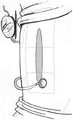
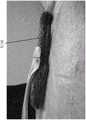
图11A-B是泡沫层5102(例如,15mm的泡沫层)在成形后被放置到伤口床5100中的照片。在图12A-C中,稳定结构5104与图2A-3E中公开的稳定结构或者本说明书中其它部分描述的任何其他稳定结构类似,呈现为伤口的形状。稳定结构可以经由剪切或其他合适的方法成形为伤口的形状,或者稳定结构可以最初具有容易被伤口容纳的尺寸。如图12B所示,稳定结构5104可以放置在伤口中。为了帮助将设备插入到伤口床中,该设备可以稍微向内或水平地变形,以便于进入伤口部位。在一些实施例中,设备可在插入期间轻微挤压,然后在与伤口壁接触时释放。在某些实施例中,伤口闭合设备5104可以如此放置,使得基质的纵向侧与伤口5100的纵向轴线对准。继续参照图12B,另一泡沫层5116(例如,10mm的泡沫层)放置在伤口闭合设备5104的顶部。11A-B are photographs of a foam layer 5102 (eg, a 15 mm layer of foam) placed into a
图12C是将端口5122施加到图12A-B的稳定结构和泡沫上的照片。泡沫5118的桥接部分可以放置成与伤口边缘处的泡沫层5116紧密接触。泡沫5118的桥接部分可以在完整的皮肤上延伸,同时一片盖布5120放置在它和完整的皮肤之间。此外,吸入端口5122可以连接到桥接部分5118,同时盖布5120的一部分位于两者之间。在替代实施例中,桥接部分5118和吸入端口5122可以在图11A-12B所示的不同步骤期间放置在伤口上。Figure 12C is a photograph of the application of
在图13中,如步骤1-4所示,该设备可以被一个或多个盖布5120覆盖。可以在覆盖泡沫桥接部分的盖布中制作孔,并且吸入端口5122可以放置在孔上。在施加盖布5120之后,可以移除一个或多个盖布的顶部表面上的保护层5124。一旦施加了盖布5120并且端口处于适当位置,就可以通过盖布从真空源向伤口施加负压。如本说明书中其他部分所述,负压可导致稳定结构水平塌缩。通过多孔层粘附到稳定结构的组织锚固件与伤口的组织接合,并且可以促进伤口的闭合。In Figure 13, the device may be covered by one or
在某些实施例中,吸入端口可以直接放置在泡沫层5116的中心部分上。在这样的实施例中,泡沫层可以在负压下与稳定结构一起向内塌缩,从而使吸入端口塌缩。为了避免塌缩,与泡沫相比,吸入端口可以是刚性的,并抵抗塌缩。垫圈可以放置在吸入端口的内部、下方或周围,以提供刚性,并抵抗塌缩。In some embodiments, the suction port may be placed directly on the central portion of the
在一些实施例中,吸入端口可以预先附接到顶部泡沫层,使得盖布可以定位在端口周围。可以使用硬端口或软端口,这些端口可以进一步与如上所述的垫圈组合使用。在进一步的实施例中,吸入端口可以仅部分地与正在塌缩的基质一起塌缩,同时仍然保持用于负压的端口开口。In some embodiments, the suction port can be pre-attached to the top foam layer so that the drape can be positioned around the port. Hard or soft ports can be used which can further be combined with gaskets as described above. In further embodiments, the suction port may only partially collapse with the collapsing matrix, while still maintaining the port opening for negative pressure.
图14A-14C提供了正在放置到伤口中的上泡沫层5116的进一步图示,接着放置桥接部分5118,并放置一个或多个盖布或伤口覆盖物5120。图14D-14G示出了用于伤口治疗和闭合的方法中的几个步骤的实施例。如图14D所示,吸入端口5122与释放衬垫5126分离,并且随后如图11A-13所示施加到伤口上。图14E示出了正在插入到负压伤口疗法设备5130中的罐(canister)5128,以便为收集伤口渗出物做准备。图14F示出了连接到吸入端口的管道和连接到负压伤口疗法设备5130的管道之间的卡扣式连接(snap connection)。一旦完成连接,就可以如图14G所示开始负压伤口治疗。14A-14C provide further illustrations of the
图15A-E是用于闭合伤口的现有技术或替代方法的照片和附图,其与图7-14G的方法具有一些相似性。在此,泡沫放置在肌肉和筋膜的下方,随后泡沫从伤口垂直延伸出来并折叠。这种方法可以提供真皮的增强闭合,但可能不在筋膜层面。在替代实施例中,通过提供从伤口凸出的折叠泡沫层5116,这种构造可以与稳定结构组合,例如本文本部分和本说明书中其他部分公开的那些稳定结构。图15E是现有技术或替代方法的横截面图。Figures 15A-E are photographs and drawings of prior art or alternative methods for closing wounds that share some similarities with the methods of Figures 7-14G. Here, the foam is placed under the muscle and fascia, which is then extended vertically from the wound and folded. This approach may provide enhanced closure of the dermis, but may not be at the fascial level. In alternate embodiments, this configuration may be combined with stabilizing structures, such as those disclosed in this text and elsewhere in this specification, by providing a folded
伤口闭合设备、稳定结构、相关装置和使用方法可与本文所述的任何实施例组合或合并,关于上述伤口闭合设备、稳定结构、相关装置和使用方法的进一步细节可在本说明书的其他部分和2013年7月16日提交的国际申请No.PCT/US2013/050698中找到,该申请的公开号为WO2014/014922A1,其全部内容通过引用并入本文。The wound closure devices, stabilizing structures, related devices, and methods of use may be combined or incorporated with any of the embodiments described herein, and further details regarding the aforementioned wound closure devices, stabilizing structures, related devices, and methods of use can be found elsewhere in this specification and Found in International Application No. PCT/US2013/050698, filed July 16, 2013, with publication number WO2014/014922A1, the entire contents of which are incorporated herein by reference.
图16-19D的稳定结构Figures 16-19D Stable structure
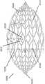
图16是稳定结构6100的实施例的附图,其类似于图2A-3E的稳定结构。稳定结构6100可以通过本文本部分或本说明书中其他部分描述的任何方式构造,例如通过3D打印,以及通过图3A-3E中描述的计算方法。此外,稳定结构6100可以由本文本部分或本说明书中其他部分描述的任何材料构造,例如关于图2A-3E描述的材料。类似于图2A-3E的稳定结构,稳定结构6100包括平行或半平行布置的多个细长条带6106,其纵向长度可与伤口的纵向轴线对准。在实施例中,细长条带6106也可以以非平行的方式布置。该稳定结构6100内的各种单元可具有各种形状和尺寸。如上文更详细描述的,细长条带6106、中间构件6110和单元6104的长度和形状可以设计成促进稳定结构的更大闭合。16 is a drawing of an embodiment of a stabilizing
在实施例中,因为包括延伸部分6120,所以图16的稳定结构与图2A-3E的稳定结构不同。延伸部分6120包括沿着稳定结构6100的纵向轴线向外延伸的一个或多个附加单元。延伸部分6120可以允许稳定结构更好地配合在长的切口性伤口内。此外,延伸部分6120的添加可用于在稳定结构6100的塌缩期间防止周围组织的挤压。延伸部分可包括约6个附加单元,12个附加单元,16个附加单元,20个附加单元,30个附加单元,或者超过30个的附加单元。In an embodiment, the stabilizing structure of FIG. 16 differs from the stabilizing structure of FIGS. 2A-3E because the
如图16所示,延伸部分6120可以包括附加行,附加行在其宽度上具有逐渐减少的单元。例如,延伸部分6120可以包括四个单元的行,接着是两个单元的行,随后是两个单元的另一行。在一些实施例中,六个单元的行位于四个单元的行之前。延伸部分6120沿着稳定结构的纵向轴线延伸超出虚拟椭圆的外侧边缘,该虚拟椭圆由稳定结构的大部分周边形成。在某些实施例中,延伸部分可以沿着纵向轴线从稳定结构的两端延伸。在一些实施例中,延伸部分6120在稳定结构的纵向边缘处为稳定结构的外壁提供阶梯式外周边,这与沿着稳定结构6122的侧面的连续外周边形成对比。As shown in FIG. 16, the
在没有延伸部分6120的情况下,稳定结构包括基本上沿着椭圆形的整个长度的非阶梯侧壁。但是,在有延伸部分的情况下,附加行可以基于附加行提供阶梯式外周边6124,这与稳定结构6126的扁平椭圆形端部形成对比。延伸部分的进一步实施例将在下文参考图17A-17E更详细地描述。Without
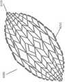
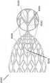
图17A-17E是稳定结构6200的实施例的附图和照片,其类似于图2A-3E和图16的稳定结构。与说明书中其他部分公开的稳定结构非常相似,稳定结构6200包括细长条带6206、单元6204和中间构件6210。稳定结构6200进一步包括位于稳定结构的纵向轴线的两端处的延伸部分6220。如上文关于图16所述,延伸部分6220可以允许稳定结构更好地配合在伤口的轮廓内。此外,延伸部分6220可以防止在稳定结构塌缩之后周围组织的挤压。如上所述,延伸部分可包括多个单元。17A-17E are drawings and photographs of an embodiment of a stabilizing
图17A-17E的稳定结构和本文本部分或本说明书中其他部分公开的任何稳定结构可以以各种尺寸生产。实际伤口的可能尺寸和形状可以在尺寸和形状方面剧烈变化,因而合适的稳定结构也可以以各种尺寸制备。例如,未塌缩的稳定结构的长度可以是大约至少25mm,50mm,75mm,100mm,125mm,150mm,175mm,200mm,250mm,300mm,350mm,400mm,450mm,500mm,750mm或大于750mm。在某些实施例中,未塌缩的稳定结构的宽度可以是至少10mm,15mm,25mm,35mm,50mm,75mm,100mm,125mm,150mm,175mm,200mm,250mm,300mm,350mm,400mm,450mm,500mm或大于500mm。The stabilizing structures of Figures 17A-17E and any of the stabilizing structures disclosed in this text or elsewhere in this specification can be produced in various sizes. The possible size and shape of actual wounds can vary drastically in size and shape, and thus suitable stabilizing structures can also be prepared in various sizes. For example, the length of the uncollapsed stabilizing structure may be approximately at least 25mm, 50mm, 75mm, 100mm, 125mm, 150mm, 175mm, 200mm, 250mm, 300mm, 350mm, 400mm, 450mm, 500mm, 750mm, or greater than 750mm. In certain embodiments, the width of the uncollapsed stabilization structure may be at least 10mm, 15mm, 25mm, 35mm, 50mm, 75mm, 100mm, 125mm, 150mm, 175mm, 200mm, 250mm, 300mm, 350mm, 400mm, 450mm, 500mm or more.
如图17E所示,在一些实施例中,未塌缩的稳定结构可具有大约242mm的长度。但是,稳定结构可以具有本文本部分或本说明书中其他部分公开的任何尺寸。稳定结构的单元6204可以具有各种尺寸,例如,单元6204的宽度可以是大约至少5mm,10mm,15mm,20mm,25mm,30mm,50mm,或大于50mm。例如,单元的长度可以是大约至少5mm,10mm,15mm,20mm,25mm,30mm,50mm或大于50mm。As shown in Figure 17E, in some embodiments, the uncollapsed stabilizing structure may have a length of approximately 242 mm. However, the stabilizing structure can have any of the dimensions disclosed in this text or elsewhere in this specification. The
在一些实施例中,延伸部分6220可以包括四个单元的第一行,随后是两个单元的行,接着是两个单元的另一行。六个单元的行可以在上述四个单元的行之前。但是,在进一步的实施例中,延伸部分可以包括不同数目的行,以及每行包括各种数目的单元。例如,延伸部分可以包括1行,2行,3行,4行,5行,6行或多于6行。在实施例中,行可包括1个单元,2个单元,3个单元,4个单元,5个单元,6个单元,8个单元,10个单元,16个单元或多于16个单元。In some embodiments,
返回图17A,在某些实施例中,延伸部分可包括一系列单元6204,单元6204包括与稳定结构的纵向轴线6230半平行的壁。这些单元壁与稳定结构中别处的单元壁形成对比,该稳定结构包括与稳定结构6200的纵向轴线成一定角度6240延伸的壁。Returning to Figure 17A, in certain embodiments, the extension may include a series of
与不包括延伸部分的稳定结构的实施例相比,在包括延伸部分6220的稳定结构的实施例中,最接近稳定结构的中心纵向轴线的细长构件6206沿着纵向轴线进一步延伸。例如,最内侧的细长条带是最长的条带,而下一个最内侧的条带是第二长的条带等等。延伸部分的存在导致当从上方观察时稳定结构看起来更偏眼睛的形状,而不是更偏椭圆的形状。In the embodiment of the stabilizing structure including the
如图17A-C所示,在实施例中,稳定结构6200可以是眼睛形。眼睛形的形状可以看起来像人眼的形状,其中弯曲的上边缘和下边缘会聚到眼角中两个纵向极处的点。在此,外壁6250向内弯曲,以在延伸部分6220处会聚。这种形状与更偏菱形的形状(未示出)形成对比,在菱形形状中外壁将以直线会聚到延伸部分6220。但是,在一些实施例中。稳定结构可以是菱形的形式,而不是眼睛形。As shown in Figures 17A-C, in an embodiment, the stabilizing
稳定结构6200还包括从稳定结构6200的外壁向外延伸的突片6212。这种突片可从稳定结构的顶部或底部向外延伸,或者同时从顶部和底部向外延伸。突片可以从稳定结构的所有外侧单元向外延伸,如图17C所示,或者突片可以如图17A所示交替。图17D是突片6212的近距离视图的照片。突片可以由本文本部分或本说明书中其他部分描述的任何材料构造,例如用于构造稳定结构的那些材料。在某些实施例中,突片可以作为稳定结构的一部分3D打印。Stabilizing
突片6212可进一步包括锚固层,例如上文参考图4-6B描述的那些锚固层。该锚固层可用于将突片粘附到泡沫层上。在实施例中,突片可以在合适的粘合剂中涂覆,从而允许突片粘附到泡沫层。下文将参考图20A-22E更详细地描述泡沫与稳定结构的上层和下层的附接。突片可进一步用于在围绕稳定结构或者位于其他结构(例如泡沫)周围的组织的上方或下方向外延伸,被包裹在稳定结构的周边。The
图17A-17E的稳定结构可以设置成各种尺寸,例如上文参考图2A-3E所述的那些尺寸。如上所述,将对稳定结构的尺寸的调整减到最少,这在临床环境中可能是有利的,因而可提供套件,该套件包括可适合于具有适当尺寸的伤口的各种尺寸的稳定结构。例如,套件可以包括仅有两种尺寸的基质,即大尺寸和小尺寸。较大尺寸的稳定结构可以是较小稳定结构的尺寸的至少约1.25倍,1.5倍,1.75倍,2倍,2.5倍,3倍,4倍,5倍,6倍或大于6倍。The stabilizing structures of Figures 17A-17E can be provided in various dimensions, such as those described above with reference to Figures 2A-3E. As discussed above, to minimize adjustments to the dimensions of the stabilizing structure, which may be beneficial in a clinical setting, kits may be provided that include stabilizing structures of various sizes that can be adapted to appropriately sized wounds. For example, a kit may include substrates in only two sizes, a large size and a small size. The larger dimension of the stabilizing structure can be at least about 1.25 times, 1.5 times, 1.75 times, 2 times, 2.5 times, 3 times, 4 times, 5 times, 6 times, or more than 6 times the size of the smaller stabilized structure.
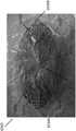
图18A-D是处于塌缩状态的图17B的稳定结构6200的多个视图的照片。在塌缩期间,稳定结构的长度和高度保持大致相同,而宽度剧烈减小。如上所述,稳定结构在受到负压时可以以这种方式塌缩,从而促进伤口的闭合。如图18A所示,在一些实施例中,延伸部分6220可以避免塌缩,但是如图18C-D所示,在实施例中,延伸部分将与稳定结构的其余部分一起塌缩。18A-D are photographs of multiple views of the
图19A-B描绘了稳定结构6300的进一步实施例,其与本文本部分或本说明书中其他部分公开的稳定结构类似于。图19A-B的稳定结构的图案包括沿着稳定结构的短轴关于镜像线6302对称取向的一系列单元。在实施例中,图19A的稳定结构具有300mm的未塌缩宽度和大约510mm的长度,而图19B的稳定结构可具有242mm的未塌缩宽度和343mm的长度。图19B的稳定结构的最大单元可以具有30mm的宽度。但是,本领域技术人员将理解,图19A-B的稳定结构可包括本文本部分或本说明书中其他部分公开的任何尺寸和形状。19A-B depict a further embodiment of a stabilizing
图20A-22E的稳定结构和泡沫层Stabilizing Structure and Foam Layers of Figures 20A-22E
图20A-22E是与稳定结构组合的泡沫层的附图和照片,所述稳定结构例如上文参考图2A-3E和16-19B所述的那些稳定结构。下文描述的泡沫层可包括本文本部分或本说明书中其他部分描述的任何类型的泡沫。可能的泡沫可包括由聚合物制成的开孔泡沫和/或网状泡沫。合适的泡沫包括由以下材料组成的泡沫:例如聚氨酯、硅树脂、疏水材料、亲水材料、开孔材料、闭孔材料、混合开闭孔的材料、网状材料、聚酯、硅树脂和/或聚乙烯醇。在实施例中,本文所述的泡沫层可包括随时间改变其特性的材料。例如,特定的泡沫可以最初是刚性的,但在潮湿时变得更柔软,和/或因材料的降解而随时间失去刚性。Figures 20A-22E are drawings and photographs of foam layers combined with stabilizing structures such as those described above with reference to Figures 2A-3E and 16-19B. The foam layer described below may comprise any type of foam described in this section or elsewhere in this specification. Possible foams may include open cell foams and/or reticulated foams made from polymers. Suitable foams include foams composed of materials such as polyurethanes, silicones, hydrophobic materials, hydrophilic materials, open cell materials, closed cell materials, mixed open and closed cell materials, reticulated materials, polyesters, silicones and/or or polyvinyl alcohol. In embodiments, the foam layers described herein may include materials that change their properties over time. For example, certain foams may be initially rigid, but become softer when wet, and/or lose rigidity over time as the material degrades.
本部分或说明书中其他部分描述的泡沫层可具有各种合适的厚度。例如,泡沫层可具有至少约1mm,3mm,5mm,10mm,15mm,20mm,25mm,30mm,35mm,40mm,45mm,50mm的厚度,或者大于50mm厚的厚度。单层泡沫可以彼此叠置(laid atop),以形成总厚度更大的泡沫,例如,可以在10mm的泡沫层的顶上放置15mm厚的泡沫层,以形成总厚度25mm的泡沫。The foam layers described in this section or elsewhere in the specification may have various suitable thicknesses. For example, the foam layer may have a thickness of at least about 1 mm, 3 mm, 5 mm, 10 mm, 15 mm, 20 mm, 25 mm, 30 mm, 35 mm, 40 mm, 45 mm, 50 mm, or a thickness greater than 50 mm thick. Single layers of foam may be laid atop one another to form a foam of greater overall thickness, eg a layer of 15mm thick foam may be placed on top of a layer of 10mm of foam to form a foam of 25mm overall thickness.
在某些实施例中,本文本部分或本说明书中其他部分描述的任何泡沫层可以预先附接到器官保护层,例如如上所述的器官保护层。例如,最接近下方器官的最低泡沫层可以在放置在伤口内之前附接到器官保护层,从而为临床医生节省了首先将器官保护层放置在伤口内的步骤。在某些实施例中,器官保护层可以预先附接到稳定结构的下侧,例如本文本部分或本说明书中其他部分所述的那些稳定结构。在实施例中,器官保护层可以附接到放置在伤口中的最底泡沫层的顶部,从而将器官保护层定位在稳定结构和最底层泡沫之间。器官保护层可以完全包住最底层泡沫或稳定结构。底层泡沫和/或器官保护层的存在可用于保护下方的肠免受因与稳定结构的直接相互作用而导致的损伤。In certain embodiments, any of the foam layers described in this section or elsewhere in this specification may be pre-attached to an organ protector, such as the organ protector described above. For example, the lowest foam layer closest to the underlying organ may be attached to the organ protector prior to placement within the wound, saving the clinician the step of first placing the organ protector within the wound. In certain embodiments, the organ protective layer may be pre-attached to the underside of a stabilizing structure, such as those described in this text or elsewhere in this specification. In an embodiment, the organ protection layer may be attached to the top of the bottommost foam layer placed in the wound, thereby positioning the organ protection layer between the stabilizing structure and the bottommost foam. The organ protector can completely encase the bottommost foam or stabilizer structure. The presence of an underlying foam and/or organ protection layer can be used to protect the underlying intestine from damage due to direct interaction with stabilizing structures.
图20A-D是伤口闭合设备6350的实施例的附图和照片,伤口闭合设备6350包括稳定结构6302(类似于上文参考图2A-3E和16A-19D描述的稳定结构)、顶部多孔泡沫层6352和底部多孔泡沫层6354。如下文将更详细描述的,顶部和底部多孔层6352和6354可以以任何期望的方式成形,以符合稳定结构6302的形状。在实施例中,顶层泡沫和底层泡沫可以在放入伤口之前附接到稳定结构6302。泡沫层的预先附接有利地减少了临床医生需要完成的步骤的数目。Figures 20A-D are drawings and photographs of an embodiment of a
如说明书中其他部分所述,稳定结构6302可包括突片6304。这些突片有利地为泡沫层附接到稳定结构提供了更大的表面面积。在没有突片的情况下,粘合剂必然需要施加到稳定结构的狭窄上边缘,从而产生潜在的不牢固的附接或不存在的附接。如上所述,突片可位于稳定结构的顶部边缘和底部边缘上。在实施例中,突片可以被覆盖在锚固件中,而不是粘合剂,例如上文参考图4-6B描述的那些锚固件。锚固件的作用非常像粘合剂,允许泡沫层在放入伤口之前附接到稳定结构。稳定结构可以预先附接到底层泡沫、顶层泡沫或两者。在某些实施例中,粘合剂可以施加到稳定结构的中心纵向细长构件上,而不是施加到突片或其他位置。通过仅将粘合剂施加到中心细长构件,稳定结构可以在没有来自泡沫的阻力的情况下塌缩。The stabilizing
图20A-D示出了伤口闭合设备的实施例,其中或者在宽度、长度上,或者在两者上,底部泡沫比顶部泡沫大。在此,泡沫从稳定结构向外延伸以形成唇缘,从而允许泡沫唇缘在周围组织层(例如筋膜)的上方或下方延伸。通过提供向下的力来抵抗由扩张的下方内脏施加的向上的力,唇缘可用于将稳定结构保持在适当位置。在某些实施例中,唇部在放置到伤口床内的期间可能需要折叠,以便允许闭合设备正确定位。此后,唇缘可以展开,并延伸到周围组织中,以帮助固定设备和对周围组织施加负压。Figures 20A-D illustrate an embodiment of a wound closure device in which the bottom foam is larger than the top foam, either in width, length, or both. Here, the foam extends outward from the stabilizing structure to form a lip, allowing the foam lip to extend above or below the surrounding tissue layer (eg, fascia). The lip can be used to hold the stabilizing structure in place by providing a downward force against the upward force exerted by the expanding underlying viscera. In certain embodiments, the lips may need to be folded during placement into the wound bed in order to allow the closure device to be properly positioned. Thereafter, the lip can be deployed and extended into the surrounding tissue to help secure the device and apply negative pressure to the surrounding tissue.
在某些实施例中,伤口闭合设备6350可以是圆顶形的。在某些实施例中,稳定结构可以是圆顶形的,和/或底层泡沫和/或顶层泡沫可以是圆顶形的。稳定结构可以如此成形,使得上表面呈凹形,而底表面呈凸形。在一些实施例中,稳定结构的上表面呈凸形,而下表面呈凹形。任何泡沫层(顶层泡沫、底层泡沫、中间层泡沫或另外的泡沫层)可包括凹形的上表面和凸形的底表面。在一些实施例中,任何泡沫层(顶层泡沫、底层泡沫、中间层泡沫或另外的泡沫层)可包括凸形的上表面和凹形的底表面。In certain embodiments, wound
顶层的尺寸可以设定为稳定结构的顶部,从而促进伤口闭合至已塌缩的稳定结构的尺寸。从基质向外延伸的唇缘可以是圆形的,以便提供在伤口内的更好配合。相反,在图20E的实施例中,底层可以小于顶层。顶层可有利地防止盖布向下拉动至稳定结构中或稳定结构和伤口边缘之间。The top layer may be sized to be the top of the stabilizing structure, thereby facilitating wound closure to the dimensions of the collapsed stabilizing structure. The lips extending outward from the matrix may be rounded to provide a better fit within the wound. Conversely, in the embodiment of Figure 20E, the bottom layer may be smaller than the top layer. The top layer can advantageously prevent the drape from being pulled down into the stabilizing structure or between the stabilizing structure and the wound edge.
在某些实施例中,泡沫层可具有本文本部分或本说明书中其他部分公开的任何厚度。底层泡沫6354可以是大约15mm厚或大约10mm厚。例如,图20D的底部泡沫6354比图20C的底部泡沫厚。In certain embodiments, the foam layer may have any thickness disclosed in this section or elsewhere in this specification. The
图20F-20G描绘了伤口闭合设备的实施例,其涉及总共3层泡沫。在此,伤口闭合设备6350包括稳定结构6302、顶层泡沫6352、底层泡沫6354和中间层泡沫6356。稳定结构可以预先附接到中间层泡沫、顶层泡沫、或两者。此外,底层泡沫可以预先附接到中间层泡沫,或者可以分别放置到伤口中。在一些实施例中,顶层是15mm或10mm厚,中间层是15mm厚,底层是10mm厚。泡沫层可以通过任何合适的方式附接,例如经由粘合剂或锚固件。如图20E所示,最底层泡沫可包括从伤口闭合设备向外延伸到周围组织中的唇缘。如上所述,这种唇缘可以将设备固定在适当位置。底层泡沫可以比中间层泡沫和/或顶层泡沫更宽和/或更长。在某些实施例中,除了位于稳定结构的顶部和底部上的泡沫之外,泡沫可以附接到稳定结构的整个外周边。泡沫可以通过任何合适的方式附接到稳定结构的周边,例如通过粘合剂或锚固层。一旦泡沫已经施加到稳定结构的周边,如果还存在顶层泡沫和底层泡沫,则稳定结构将不再可见。20F-20G depict an embodiment of a wound closure device involving a total of 3 layers of foam. Here, wound
在图20A-20F的泡沫层的实施例中,泡沫层可包含本文本部分或本说明书中其他部分描述的任何类型的合适的泡沫材料。例如,泡沫可包括“黑色泡沫”(例如聚氨酯)和/或包含聚乙烯醇(PVA)的“白色泡沫”。在涉及PVA泡沫的实施例中,与其他类型的泡沫相比,可能需要更薄的泡沫层,因为PVA泡沫通常比其他类型的泡沫更具弹性和致密性。此外,一旦PVA泡沫变湿,它可能还有助于横向滑动。在一些实施例中,泡沫层可以与其他填料(例如纱布)或其他网眼状/网状产品(例如Fry和Kossel上的那些)组合。In the foam layer embodiment of Figures 20A-20F, the foam layer may comprise any type of suitable foam material described in this text or elsewhere in this specification. For example, the foam may include "black foam" (eg, polyurethane) and/or "white foam" containing polyvinyl alcohol (PVA). In embodiments involving PVA foam, a thinner foam layer may be required as compared to other types of foam, since PVA foam is generally more resilient and denser than other types of foam. Also, once the PVA foam gets wet, it may also help with lateral sliding. In some embodiments, the foam layer may be combined with other fillers (eg gauze) or other mesh/mesh products (eg those on Fry and Kossel).
图21是泡沫层4600的实施例的照片,其可以与本文本部分或本说明书中其他部分描述的任何稳定结构或伤口闭合设备组合使用。泡沫层4600可以用于替代本文本部分或本说明书中其他部分描述的任何泡沫层。如本部分和说明书中其他部分所述,泡沫层4600可位于稳定结构或伤口闭合设备的上方或下方。在一些实施例中,泡沫层4600位于稳定结构或伤口闭合设备的上方和下方。泡沫层4600可以围绕稳定结构或伤口闭合设备的周边,或者完全围绕整个稳定结构或伤口闭合设备。泡沫层4600可以由吸收性材料、构造成分配流体的材料或这两种材料构造。Figure 21 is a photograph of an embodiment of a
泡沫层4600还包括指状物4602,指状物4602可从泡沫层延伸到稳定结构或闭合设备中。例如,指状物4602可以延伸到在本文本部分或本说明书中其他部分所述的稳定结构中描绘的间隙或单元中,并且在这些间隙或单元的周围延伸。指状物4602还可以在稳定结构的周边外侧的周围延伸。在一些实施例中,来自一个泡沫层4600的指状物4602可以延伸穿过稳定结构的内部,或者在稳定结构的外部的周围延伸,以与第二泡沫层4600的指状物4602相接触。因而,一个泡沫层将面向指状物侧朝上,而第二泡沫层可以面向指状物侧朝下。The
在一些实施例中,泡沫层4600可具有穿孔或预切口,以允许部分泡沫层4600容易被撕掉,从而使用于特定伤口的泡沫成形。在一些实施例中,指状物4602可从泡沫层的表面延伸至少约1mm,从泡沫层的表面延伸至少约3mm,从泡沫层的表面延伸至少约5mm,从泡沫层的表面延伸至少约7.5mm,从泡沫层的表面延伸至少约10mm,从泡沫层的表面延伸至少约12.5mm,从泡沫层的表面延伸至少约25mm,从泡沫层的表面延伸至少约17.5mm,从泡沫层的表面延伸至少约20mm,从泡沫层的表面延伸至少约25mm,或者从泡沫层的表面延伸大于25mm。In some embodiments, the
在某些实施例中,可以改变指状物4602,以便控制稳定结构的塌缩。例如,当指状物延伸到稳定结构的特定单元中时,指状物将防止该特定单元的塌缩。因此,延伸到稳定结构中的较大数量的泡沫指状物与较少数量的泡沫指状物相比,将减少更多的塌缩。例如,指状物可以延伸进入稳定结构的单元的至少约10%、20%、30%、50%、75%或甚至100%,从而进一步限制稳定结构的塌缩。In certain embodiments, the
图22A-22E描绘了适用于印刷说明的泡沫。当放置伤口闭合设备(例如本文本部分或本说明书中其它部分描述的那些伤口闭合设备)时,临床医生可能难以确定泡沫层或伤口闭合设备的其他部件的正确取向。因此,在泡沫上印刷符号可以使临床医生更容易正确地取向泡沫层。尽管未示出,但是本文本部分或本说明书中其他部分公开的任何符号或印迹可以应用于伤口闭合设备的不同结构,例如稳定结构。Figures 22A-22E depict foam suitable for printing instructions. When placing a wound closure device, such as those described in this text or elsewhere in this specification, it may be difficult for a clinician to determine the correct orientation of the foam layer or other components of the wound closure device. Therefore, printing the symbols on the foam can make it easier for the clinician to properly orient the foam layer. Although not shown, any symbols or imprints disclosed in this text section or elsewhere in this specification may be applied to different structures of the wound closure device, such as stabilizing structures.
图22A描绘了简单的未标记的泡沫椭圆6400,除了泡沫的大体形状之外,这种层对于泡沫在伤口中的正确取向几乎提供不了什么引导。图22B描绘了包括水平条纹6402的泡沫层的实施例。这些水平条纹可以沿着伤口的较短轴线对准,从而提供泡沫椭圆形6400的易于放置。类似地,图22C描绘了包括纵向条纹6404的椭圆形泡沫层,该纵向条纹6404可以与伤口的纵向轴线对准。图22D类似于图22B,因为水平箭头6404表示与伤口的水平轴线对准。最后,图22E将纵向条纹6404与水平箭头6404组合,但进一步包括符号“头部”6408和“脚部”6410,以指导临床医生将该头部取向成朝向患者的头部,并且将该脚部取向成朝向患者的脚部。Figure 22A depicts a simple
在某些实施例中,与图22B-E的泡沫层类似的泡沫层可包括在泡沫层的一侧或两侧上印刷,以向临床医生指示泡沫或伤口闭合设备的哪一侧是顶部,哪一侧是底部。精确描绘设备的顶部、底部和取向的印刷可以防止临床医生在将伤口闭合设备放置在伤口中时上下颠倒或者以错误的方向旋转。In certain embodiments, a foam layer similar to that of Figures 22B-E may include printing on one or both sides of the foam layer to indicate to the clinician which side of the foam or wound closure device is the top, Which side is the bottom. Printing that accurately delineates the top, bottom and orientation of the device can prevent clinicians from turning the wound closure device upside down or in the wrong direction when placing the wound closure device in the wound.
图23A是数据表,其追踪伤口闭合设备的实施例的塌缩(通过测量宽度的减小),同时该设备承受增加的真空水平,该伤口闭合设备并入了与图2A-3E和16-20F的结构类似的稳定结构。此处,泡沫附接到稳定结构的顶部和底部,类似于图20A-20F的实施例,并且整个设备放置在动物模型内。真空从40mm Hg增加到200mm Hg。该设备的预真空的宽度为123.4mm,在真空下该宽度降至83.4mm。图23B以条形图的形式显示图23A的实验数据。23A is a data sheet that tracks the collapse (by measuring the reduction in width) of an embodiment of a wound closure device that is subject to increasing vacuum levels, the wound closure device incorporating the The structure of 20F is similar to the stable structure. Here, the foam is attached to the top and bottom of the stabilizing structure, similar to the embodiment of Figures 20A-20F, and the entire device is placed within the animal model. The vacuum was increased from 40mm Hg to 200mm Hg. The pre-vacuum width of the device was 123.4mm, which dropped to 83.4mm under vacuum. Figure 23B shows the experimental data of Figure 23A in the form of a bar graph.
各种传感器可以放置在本文本部分或本说明书中其他部分描述的任何稳定结构或泡沫层内。例如,pH传感器、温度传感器、压力传感器或任何其他合适的传感器可以嵌入在稳定结构内和/或泡沫层内。这样的实施例将有利地允许临床医生跳过移除伤口床内的传感器的步骤,因为在移除稳定结构或泡沫时就简单地移除了传感器。The various sensors can be placed within any stable structure or foam layer described in this text section or elsewhere in this specification. For example, pH sensors, temperature sensors, pressure sensors, or any other suitable sensor may be embedded within the stabilizing structure and/or within the foam layer. Such an embodiment would advantageously allow the clinician to skip the step of removing the sensor within the wound bed, as the sensor is simply removed when the stabilizing structure or foam is removed.
图24A-29的稳定结构Stabilizing Structures of Figures 24A-29
图24A-29是稳定结构6500的各种实施例的附图和照片。除非另有说明,否则图24A-29中的附图标记表示与前述附图中的部件相同或大致相似的部件。应当理解,图24A-29中所示的稳定结构可以与本文描述和/或考虑的任何实施例一起使用。还应该理解,可以修改本文描述和/或考虑的任何实施例,以与图24A-29中所示的稳定结构一起使用。24A-29 are drawings and photographs of various embodiments of a stabilizing
如在本部分或本说明书中其他部分所使用的,当涉及稳定结构时,x方向通常是指大致平行于围绕伤口的皮肤的方向或平面。当涉及稳定结构时,y方向通常是指大致平行于围绕伤口的皮肤并垂直于x方向延伸的方向或平面。当涉及稳定结构时,z方向通常是指垂直于x方向和y方向延伸的方向或平面。当涉及稳定结构时,术语“宽度”通常是指沿x方向截取的稳定结构最长的尺寸。当涉及稳定结构时,术语“长度”通常是指沿y方向截取的稳定结构最长的尺寸。当提到稳定结构时,术语“高度”通常是指沿z方向截取的稳定结构最长的尺寸。术语“宽度”、“长度”和“高度”也可用于描述整个说明书中描述的稳定结构和伤口闭合设备内的单元。当描述这些结构或设备时,这些术语不应被解释为要求结构或设备必须以某个取向放置到伤口中,尽管在某些实施例中,可能优选这样做。As used in this section or elsewhere in this specification, when referring to stabilizing structures, the x-direction generally refers to a direction or plane that is generally parallel to the skin surrounding the wound. When referring to stabilizing structures, the y-direction generally refers to a direction or plane that extends generally parallel to the skin surrounding the wound and perpendicular to the x-direction. When referring to stabilizing structures, the z-direction generally refers to the direction or plane extending perpendicular to the x- and y-directions. When referring to a stabilizing structure, the term "width" generally refers to the longest dimension of the stabilizing structure taken along the x-direction. When referring to a stabilizing structure, the term "length" generally refers to the longest dimension of the stabilizing structure taken along the y-direction. When referring to a stabilizing structure, the term "height" generally refers to the longest dimension of the stabilizing structure taken along the z-direction. The terms "width", "length" and "height" may also be used to describe the stabilizing structures and elements within the wound closure device described throughout this specification. When describing these structures or devices, these terms should not be interpreted as requiring that the structures or devices must be placed into the wound in a certain orientation, although in some embodiments this may be preferred.
如上所述,本文本部分或本说明书中其他部分所述的所有稳定结构可以制作成适应任何尺寸的伤口。在一些实施例中,稳定结构的尺寸可以设计成更好地适应临床环境的需要。在某些实施例中,未塌缩的稳定结构6500的高度可以是至少1mm,5mm,10mm,15mm,20mm,25mm,30mm,35mm或大于35mm。例如,未塌缩的稳定结构6500的高度可以在25mm和30mm之间。As noted above, all of the stabilizing structures described in this section or elsewhere in this specification can be made to accommodate wounds of any size. In some embodiments, the stabilizing structure can be sized to better suit the needs of the clinical environment. In certain embodiments, the height of the
稳定结构6500可以通过本文本部分或说明书中其他部分描述的任何方式构造。稳定结构6500还可以由本部分或本说明书中其他部分描述的任何材料构成。例如,稳定结构6500可包括聚氨酯。另外,稳定结构6500可以通过各种方式构造,和/或由各种材料构成,以改变稳定结构6500的不同部分中的材料特性。在一些实施例中,可以基于材料的杨氏模量来选择材料,以优化稳定结构6500的刚度和影响稳定结构6500的闭合。例如,在向稳定结构6500施加负压时,杨氏模量可以影响单元6504的尺寸和/或稳定结构6500的宽度。在给定的负压下,更高的杨氏模量通常可导致稳定结构6500的较少闭合和单元6504的较大尺寸。另外,材料选择可以考虑老化的影响,并且考虑一些消毒方法可能对稳定结构6500的杨氏模量有影响。因此,在一些实施例中,稳定结构6500可以包括具有杨氏模量的材料,其在y和z方向上提供足够的刚度,同时维持足够的支撑,以在向稳定结构6500施加负压时,使单元6504保持开放状态,以用于流体管理。在某些实施例中,取决于为稳定结构6500选择的材料和固化方案,稳定结构6500的杨氏模量可以在至少0.5MPa,1MPa,2MPa,3MPa,4MPa,5MPa,6MPa,7MPa,8MPa,9MPa,10MPa,11MPa,12MPa,13MPa,14MPa,15MPa,16MPa,17MPa,18MPa,19MPa,20MPa,21MPa,22MPa或大于22MPa。另外,稳定结构6500可以通过各种方式构造,和/或由各种材料构成,以改变稳定结构6500的不同部分中的材料特性。Stabilizing
在一些实施例中,还可以基于材料的邵氏硬度来选择材料,以优化稳定结构6500的刚度,并影响稳定结构6500的闭合。在某些实施例中,取决于为稳定结构6500选择的材料,稳定结构6500的邵氏硬度可以是至少40邵氏硬度,50邵氏硬度,60邵氏硬度,70邵氏硬度,80邵氏硬度,90邵氏硬度或大于90邵氏硬度。此外,稳定结构6500可由各种材料构成,以改变稳定结构6500中的不同部分的邵氏硬度。In some embodiments, materials may also be selected based on their Shore hardness to optimize the stiffness of the stabilizing
图24A-24C是形成俯视图的稳定结构6500的实施例的附图,该稳定结构6500包括平行或半平行布置的多个细长条带或壁6506,细长条带或壁6506的纵向长度可与伤口的纵向轴线对准。在一些实施例中,细长条带或壁6506也可以以非平行的方式布置。由稳定结构6500限定的各种单元6504可具有各种形状和尺寸。如下文将更详细描述的,细长条带或壁6506、中间构件或壁6510和单元6504的长度和形状可以在整个稳定结构6500中设计和变化,以促进稳定结构6500的更大闭合。24A-24C are drawings forming a top view of an embodiment of a stabilizing
稳定结构6500可包括多个相邻行的单元6504,其平行于稳定结构6500的中心横向轴线,并且沿着稳定结构6500的纵向轴线居中设置。行和单元可以如此的方式设计,以在施加负压时促进稳定结构6500的闭合。在一些实施例中,与外侧行的单元6504相比,中心行的单元6504可以具有最大长度,并且延伸穿过稳定结构6500的宽度。中心行可以与较小的行相邻,同时其余行沿着纵向轴线朝向纵向端部6530逐步地逐行变小。The stabilizing
在一些实施例中,行包括具有各种尺寸的菱形单元6504。中心行可包括位于较大的类菱形单元6522内的较小的菱形单元6520。这种设计可以提供稳定设备6500的更大的整体闭合,从而提供伤口的最大程度闭合。位于较大的菱形6522内的较小的类菱形形状6520也可以将载荷分布在更大的区域上,从而减少损伤基质下方的组织结构的机会。中心行可进一步包括额外的菱形单元6504。In some embodiments, a row includes diamond-shaped
其余行可包含不同尺寸的菱形单元6504。如图24B所示,可以在每个单元6054的两个对角线中较短的一个上测量单元6504的宽度。然后,单元6504的长度可以指代每个单元6054的两个对角线中较长的那个。在一些实施例中,每行可以包括交替宽度的单元6504。例如,最中心的单元6504可以具有最大的宽度,如图24B中的长度5所示。行中的相邻单元6504可以具有较小的长度6,同时后面的单元6504的宽度7大于前一单元6054的宽度6。以这种方式,同一行内的单元可以在较小和较大的宽度之间交替。在某些实施例中,稳定结构6500可进一步包含位于稳定结构6500的不同部分中的单元之间的单元尺寸变化。The remaining rows may contain
虽然本文本部分或本说明书中其他部分描述的实施例涉及菱形单元6504,但是应当理解,单元6504的位置、形状和相对尺寸可以针对任何合适的实施例进行修改,并且它们的相对比例在各种实施例中可以不同。Although the embodiments described in this text or elsewhere in this specification refer to diamond-shaped
细长条带或壁6506和/或中间构件或壁6510的壁厚可以变化,以在施加负压时影响稳定结构6500的宽度或各个单元6504的尺寸。在一些实施例中,可以增加壁厚,以增加稳定结构6500的刚度和体积,从而导致稳定结构6500在闭合期间的更大宽度。在某些实施例中,细长条带或壁6506和/或中间构件或壁6510的壁厚可以是至少0.5mm,1mm,1.5mm,2mm,2.5mm或大于2.5mm。例如,壁厚可以在1.5mm和2mm之间。另外,稳定结构6500可包括具有各种壁厚的细长条带或壁6506和/或中间构件或壁6510,以便当稳定结构6500插入到伤口中时,在负压施加到伤口时,改变稳定结构6500的塌缩,因而促进稳定结构6500在塌缩期间的闭合。在某些实施例中,稳定结构6500可进一步包含位于稳定结构6500的不同部分中的壁之间的壁厚变化。The wall thickness of the elongated strips or
由于包括节点6540,图24A-26的稳定结构6500可以不同于图2A-3E和16-19D的稳定结构。节点6540包括两个或更多个细长条带或壁6506和/或中间构件或壁6510的交叉部。在一些实施例中,如图24C-26所示,节点6540可进一步包括铰链6542,铰链6542由细长条带或壁6506和/或中间构件或壁6510的可变壁厚产生。壁可以在每个端部向内逐渐变细,以在节点6540处形成铰链6542。当稳定结构6500插入到伤口中时,在负压施加到伤口的时候,铰链6542可以允许稳定结构6500增加节点6540处的一个或多个壁之间的旋转,从而促进稳定结构6500在塌缩期间的闭合。图25-27进一步示出了稳定结构6500、6600;壁6506、6606的厚度;以及节点6540、6640的各种实施例。例如,图25-26都示出了具有节点6540的稳定结构6500,节点6540包括铰链6542;但是,与图25相比,图26中所示的稳定结构6500沿着整个壁长度具有增加的壁6506的厚度。在替代实施例中,如图27所示,稳定结构6500可具有单一厚度的壁,因而可在节点6640处不包括铰链6542。The stabilizing
节点6540可进一步具有各种内半径6544,以在负压施加时影响稳定结构6500的宽度或各个单元6504的尺寸。在一些实施例中,可以增加内半径6544,以便还通过增加壁厚度和壁刚度来增加稳定结构6500的刚度,从而允许在塌缩期间更少的壁弯曲靠近节点6540。这还可导致稳定结构6500在闭合期间的更大宽度。另外,增加的内半径6544进一步增加了在塌缩期间在单元6504的拐角处形成的流体通道的尺寸。在某些实施例中,未塌缩的单元6504的内半径6544可以是至少0.1mm,0.2mm,0.3mm,0.4mm,0.5mm,0.6mm,0.7mm,0.8mm,0.9mm,1.0mm,1.1mm,1.2mm,1.3mm,1.4mm,1.5mm或大于1.5mm。例如,未塌缩的单元6504的内半径6544可以在0.55mm和1.0mm之间。在某些实施例中,稳定结构6500可进一步包含位于稳定结构6500的不同部分中的单元之间的内半径变化。
除了上述稳定结构6500内的单元6504的布置之外,稳定结构6500的单元6504尺寸的长度和形状可以进一步设计成在施加负压时增加稳定结构6500的闭合。在一些实施例中,稳定结构6500可进一步包含位于中心部分内的单元和位于稳定结构6500的纵向端部6530内的单元之间的尺寸变化。单元的尺寸和构造设计成促进稳定结构在纵向端部内和位于纵向端部之间的中心部分内均匀塌缩。图28A-28B是稳定结构6500的实施例的照片,其类似于图2A-3E、16D-19和24A-24C的稳定结构。与说明书中其他部分公开的稳定结构非常相似,稳定结构6500包括细长条带或壁6056、单元6504以及中间构件或壁6510。在一些实施例中,稳定结构6500可进一步包括两个纵向端部6530A,6530B,其中单元尺寸有变化,以进一步促进稳定结构6500的闭合。例如,如图28A-28E所示,从纵向右侧端部开始的第二行和第三行至最后一行移除了若干中间构件或壁6510,以相对于单元6505A增加单元6505B的尺寸和宽度。增加的单元6504尺寸可以设计成促进稳定结构6500的闭合。图28C-28E是图28A-28B的稳定结构6500处于塌缩状态的多个视图的照片。在塌缩期间,稳定结构的长度和高度保持不变,而宽度显着减小。另外,如图28C所示,单元尺寸6504B的增加导致稳定结构6500的纵向端部6530B的塌缩增大,使得在施加负压时,纵向端部的宽度与中心横向轴线处的宽度大致相同。图28D-28E提供了两个纵向端部6530A、6530B的放大视图。虽然图28A-28E将稳定结构6500显示为仅有右侧纵向端部6530B包括增加的单元6505B尺寸,但应理解纵向端部6530A,纵向端部6530B或两个纵向端部6530A、6530B的组合可以具有增加的单元6505B尺寸,以便在施加负压时促进稳定结构6500的闭合。另外,应想到(contemplate)可以移除壁6506或壁6510的任何组合,以获得期望的单元6504的尺寸和稳定结构6500的闭合。In addition to the arrangement of
可期望设计稳定结构6500的纵向边缘或其他外侧部分,以增加纵向边缘部分6530的塌缩。在某些实施例中,稳定结构6500可包括在其纵向端部6530和/或外壁处或附近的开放单元。例如,如图29所示,开放单元6704可以具有在连接到相邻单元之前终止的壁。开放单元6704的终止端6706可以朝向中心横向轴线弯曲。在一些实施例中,终止端6706可包括各种类型的端部。例如,在某些实施例中,终止端6706可包括圆形端部或成角度的端部。当稳定结构6500插入到伤口中时,开放单元6706在负压施加到伤口时可以改变稳定结构6500的塌缩,从而促进稳定结构6500在塌缩期间的闭合。该设计可降低稳定结构6500边缘处的刚度,因而在负压施加时增加稳定结构6500的塌缩。It may be desirable to design the longitudinal edge or other outboard portion of the
稳定结构6500可以设计成在施加或不施加负压的情况下以本部分或本说明书中其他部分描述的任何方式塌缩。例如,稳定结构6500可以随着负压增加而以渐进的方式塌缩。在一些实施例中,特定单元6504可在其他单元6504之前塌缩。例如,邻近稳定结构6500的外侧边缘的单元6504和/或远离稳定结构6500的中心纵向轴线的单元6504可在邻近稳定结构6500的内侧部分的单元6504和/或更靠近稳定结构6500的中心纵向轴线的单元6504之前塌缩。位于稳定结构6500的中心行内的单元6504可在位于纵向端部6530上的单元6504之前塌缩。另外,稳定结构6500和本部分或本说明书中其他部分描述的所有稳定结构和伤口闭合设备可以动态的方式按照各种时间表塌缩。在某些实施例中,各种单元6504可设计为比其他单元6504以更快的速度塌缩。Stabilizing
用稳定结构治疗伤口的方法可包括将本文本部分和本说明书中其他部分描述的稳定结构插入到伤口中,用伤口覆盖物覆盖稳定结构,以及施加负压,以使稳定结构的单元塌缩。在某些实施例中,稳定结构6800可设计成随着负压增加而以渐进的方式塌缩。例如,在一些实施例中,如图30所示,特定单元6804可在其他单元6805之前塌缩。位于稳定结构6800的中心行内的单元6804可在位于纵向端部6830上的单元6805之前塌缩。在一些实施例中,稳定结构可以设计成允许纵向端部与稳定结构的其余部分均匀地或一致地塌缩。图28A-28E是描绘用于治疗伤口的方法的实施例的照片,该方法使用包括稳定结构的伤口闭合设备,该稳定结构在位于中心部分内的单元和位于稳定结构6500的纵向端部6530内的单元之间具有尺寸变化。图28A描绘了具有单元尺寸变化的稳定结构6500的实施例。图28B描绘了放置在半透明可密封袋内的稳定结构,以观察稳定结构的闭合。图28C描绘了在负压施加之后位于半透明可密封袋内的稳定结构6500。图28E描绘了稳定结构6500的实施例,其中单元6505B已被修改,以使纵向端部6530B中的单元6505B与稳定结构6500的中心部分的单元均匀地塌缩。可以将图28E与图28D进行对比。图28D描绘了稳定结构6500的纵向端部6530A的实施例,其中没有移除中间构件或壁6510,从而维持了单元6505A的尺寸和宽度。因此,纵向端部6530A中的单元6505A不会与中心部分中的单元或稳定结构6500的纵向端部6530B中的单元6505B均匀地或一致地塌缩,如图28C和28E所示。A method of treating a wound with a stabilizing structure may include inserting a stabilizing structure described in this text and elsewhere in this specification into a wound, covering the stabilizing structure with a wound cover, and applying negative pressure to collapse the elements of the stabilizing structure. In certain embodiments, the stabilizing
尽管本公开描述了某些实施例,但是本领域技术人员将理解,可以对本公开示出和描述的方法和设备的许多方面做出不同地组合和/或修改,以形成更进一步的实施例或者可接受的示例。所有这些修改和变化旨在包括在本公开的范围内。实际上,各种各样的设计和方法都是可能的,并且在本公开的范围内。本文公开的特征、结构或步骤不是必需的或必不可少的。此外,虽然本文已经描述了说明性实施例,但是基于本公开内容,本领域技术人员将理解具有等同元件、修改、省略、组合(例如,跨各种实施例的方面的)、替换、改编和/或改变的任何和所有实施例的范围。虽然已经描述了某些实施例,但是这些实施例仅作为示例呈现,并且不旨在限制保护范围。Although this disclosure has described certain embodiments, those skilled in the art will appreciate that the various aspects of the methods and apparatus shown and described in this disclosure may be variously combined and/or modified to form still further embodiments or acceptable example. All such modifications and variations are intended to be included within the scope of this disclosure. Indeed, a wide variety of designs and methods are possible and within the scope of this disclosure. No feature, structure, or step disclosed herein is required or essential. Furthermore, although illustrative embodiments have been described herein, those skilled in the art will appreciate, based on this disclosure, equivalent elements, modifications, omissions, combinations (eg, across aspects of the various embodiments), substitutions, adaptations and /or vary the scope of any and all embodiments. While certain embodiments have been described, these embodiments have been presented by way of example only, and are not intended to limit the scope of protection.
结合特定方面、实施例或示例描述的特征、材料、特性或分组应被理解为适用于本部分或本说明书中其他部分描述的任何其他方面、实施例或示例,除非与其不相容。本说明书中公开的所有特征(包括任何所附权利要求、摘要和附图),和/或如此公开的任何方法或过程的所有步骤,可以以任何组合进行组合,除非在组合中至少一些这样的特征和/或步骤是互斥的。保护不限于任何前述实施例的细节。保护延伸到本说明书(包括任何所附权利要求、摘要和附图)中公开的特征的任何新颖的特征或任何新颖组合,或者保护延伸到如此公开的任何方法或过程的步骤的任何新颖的步骤或任何新颖的组合。Features, materials, characteristics or groupings described in connection with a particular aspect, embodiment or example should be understood to be applicable to any other aspect, embodiment or example described in this section or elsewhere in this specification unless incompatible therewith. All features disclosed in this specification (including any accompanying claims, abstract and drawings), and/or all steps of any method or process so disclosed, may be combined in any combination unless at least some of such Features and/or steps are mutually exclusive. Protections are not limited to the details of any preceding embodiment. Protection extends to any novel feature or any novel combination of features disclosed in this specification (including any accompanying claims, abstract and drawings), or to any novel step of any method or process so disclosed or any novel combination.
此外,在单独实现的情况下在本公开中描述的某些特征也可以在单个实现中组合实现。相反,在单个实现的上下文中描述的各种特征也可以单独地或以任何合适的子组合在多个实现中实现。此外,尽管特征在上文可以描述为在某些组合中起作用,但是在一些情况下,来自所要求保护的组合的一个或多个特征可以从组合中去除,并且该组合可以作为子组合或子组合的变化而要求保护。Furthermore, certain features that are described in this disclosure in the context of separate implementations can also be implemented in combination in a single implementation. Conversely, various features that are described in the context of a single implementation can also be implemented in multiple implementations separately or in any suitable subcombination. Furthermore, although features may be described above as functioning in certain combinations, in some cases one or more features from the claimed combination may be removed from the combination and the combination may be used as a subcombination or Changes in sub-combinations are claimed.
此外,虽然操作可以特定的顺序在附图中描绘或者在说明书中描述操作,但是这样的操作不需要以所示的特定顺序执行,或者按顺序执行,或者执行所有操作,以实现期望的结果。未描绘或描述的其他操作可以并入示例的方法和过程中。例如,可以在任何所描述的操作之前、之后、同时或之间执行一个或多个附加操作。此外,可以在其他实现中重新布置或重新排序操作。本领域技术人员将理解,在一些实施例中,所示和/或所公开的过程中采取的实际步骤可以不同于附图中所示的步骤。取决于实施例,可以去除上述某些步骤,可以添加其他步骤。此外,上文公开的特定实施例的特征和属性可以以不同的方式组合,以形成另外的实施例,所有这些实施例都落入本公开的范围内。同样,上述实施中的各种系统组件的分离不应被理解为在所有实施中都需要这种分离,并且应当理解,所描述的组件和系统通常可以在单个产品中集成在一起,或者封装到多个产品中。Additionally, although operations may be depicted in the drawings or described in the specification in a particular order, such operations need not be performed in the particular order shown, or sequential order, or all operations, to achieve desirable results. Other operations not depicted or described may be incorporated into the example methods and processes. For example, one or more additional operations may be performed before, after, concurrently with, or between any of the described operations. Furthermore, operations may be rearranged or reordered in other implementations. Those skilled in the art will understand that, in some embodiments, the actual steps taken in the processes shown and/or disclosed may differ from the steps shown in the figures. Depending on the embodiment, some of the steps described above may be eliminated and other steps may be added. Furthermore, the features and attributes of the specific embodiments disclosed above may be combined in different ways to form additional embodiments, all of which fall within the scope of the present disclosure. Likewise, the separation of various system components in the above-described implementations should not be construed as requiring such separation in all implementations, and it should be understood that the described components and systems may typically be integrated together in a single product, or packaged into in multiple products.
出于本公开的目的,本文描述了某些方面、优点和新颖特征。不一定所有这些优点可以根据任何特定实施例实现。因而,例如,本领域技术人员将认识到,本公开可以以实现本文所教导的一个优点或一组优点的方式实现或实施,而不一定实现本文可能教导或建议的其他优点。For the purposes of the present disclosure, certain aspects, advantages and novel features have been described herein. Not necessarily all of these advantages may be realized in accordance with any particular embodiment. Thus, for example, those skilled in the art will recognize that the present disclosure may be realized or practiced in a manner that achieves one advantage or group of advantages as taught herein without necessarily achieving other advantages that may be taught or suggested herein.
条件语言,例如“可以(can)”、“可以(could)”、“可能(might)”或“可能(may)”,除非另有明确说明,或者在所使用的上下文中以其他方式理解,通常旨在表达某些实施例包括,而其他实施例不包括,某些特征、元件和/或步骤。因而,这种条件语言通常不旨在暗示一个或多个实施例以任何方式需要特征、元素和/或步骤,或者一个或多个实施例必须包括用于在有或没有用户输入或提示的情况下决定的逻辑,在任何特定实施例中是否包括或将要执行这些特征、元素和/或步骤。Conditional language, such as "can," "could," "might," or "may," unless expressly stated otherwise, or otherwise understood in the context in which it is used, It is generally intended to express that some embodiments include, and other embodiments do not, certain features, elements and/or steps. Thus, such conditional language is generally not intended to imply that one or more embodiments require features, elements, and/or steps in any way, or that one or more embodiments must be included for use with or without user input or prompting Logic that determines whether these features, elements and/or steps are included or are to be performed in any particular embodiment.
除非另有明确说明,否则诸如短语“X,Y和Z中的至少一个”的联合语言在上下文中被理解为通常用于表示项目、术语等可以是X,Y或Z。因而,这种联合语言通常不旨在暗示某些实施例需要存在至少一个X、至少一个Y和至少一个Z。Conjunctive language such as the phrase "at least one of X, Y, and Z" is contextually understood to be generally used to mean that an item, term, etc. may be X, Y, or Z unless expressly stated otherwise. Thus, this association language is generally not intended to imply that certain embodiments require the presence of at least one X, at least one Y, and at least one Z.
本文使用的程度语言,例如本文所用的术语“大约”,“约”,“大致”和“基本”,表示接近所述数值、数量或特征的数值,数量或特征,其仍然执行所期望的功能或实现所期望的结果。例如,术语“大约”,“约”,“大致”和“基本”可以指数量在少于所述数量的10%以内,少于5%以内,少于1%以内,少于0.1%以内,少于0.01%以内。作为另一示例,在某些实施例中,术语“大致平行”和“基本上平行”是指数值、数量或特征偏离准确平行的程度为小于或等于15度,10度,5度,3度,1度,0.1度,或其他。Language of degree used herein, such as the terms "about," "about," "approximately," and "substantially," as used herein, means a value, quantity, or feature that approximates the stated value, quantity, or feature, which still performs the desired function or achieve the desired result. For example, the terms "about", "about", "approximately" and "substantially" can refer to an amount within 10% of the stated amount, within less than 5%, within less than 1%, within less than 0.1%, less than 0.01%. As another example, in certain embodiments, the terms "substantially parallel" and "substantially parallel" refer to an index value, quantity or feature that deviates from exact parallel by less than or equal to 15 degrees, 10 degrees, 5 degrees, 3 degrees , 1 degree, 0.1 degree, or other.
本公开的范围不旨在受本部分或本说明书中其他部分的优选实施例的具体公开内容的限制,并且本公开的范围可以由本部分或本说明书中其他部分所呈现的权利要求限定,或者由将来呈现的权利要求限定。权利要求的语言将基于权利要求中采用的语言广泛地解释,并且不限于本说明书中或者在申请的审查期间描述的示例,这些示例应被解释为非排他性的。The scope of the disclosure is not intended to be limited by the specific disclosure of the preferred embodiments in this section or elsewhere in this specification, and the scope of the disclosure may be defined by the claims presented in this section or elsewhere in this specification, or by Future-presented claims define. The language of the claims is to be interpreted broadly based on the language employed in the claims, and is not limited to the examples described in this specification or during prosecution of the application, which should be construed as non-exclusive.
Claims (49)
Applications Claiming Priority (3)
| Application Number | Priority Date | Filing Date | Title |
|---|---|---|---|
| US201662416570P | 2016-11-02 | 2016-11-02 | |
| US62/416,570 | 2016-11-02 | ||
| PCT/US2017/059603WO2018085457A1 (en) | 2016-11-02 | 2017-11-01 | Wound closure devices |
Publications (2)
| Publication Number | Publication Date |
|---|---|
| CN110167495A CN110167495A (en) | 2019-08-23 |
| CN110167495Btrue CN110167495B (en) | 2022-06-14 |
Family
ID=60331703
Family Applications (1)
| Application Number | Title | Priority Date | Filing Date |
|---|---|---|---|
| CN201780080270.XAActiveCN110167495B (en) | 2016-11-02 | 2017-11-01 | Wound closure device |
Country Status (6)
| Country | Link |
|---|---|
| US (1) | US11617684B2 (en) |
| EP (1) | EP3534856A1 (en) |
| JP (1) | JP2019532774A (en) |
| CN (1) | CN110167495B (en) |
| CA (1) | CA3042673A1 (en) |
| WO (1) | WO2018085457A1 (en) |
Families Citing this family (29)
| Publication number | Priority date | Publication date | Assignee | Title |
|---|---|---|---|---|
| GB0808376D0 (en) | 2008-05-08 | 2008-06-18 | Bristol Myers Squibb Co | Wound dressing |
| GB0817796D0 (en) | 2008-09-29 | 2008-11-05 | Convatec Inc | wound dressing |
| GB201020236D0 (en) | 2010-11-30 | 2011-01-12 | Convatec Technologies Inc | A composition for detecting biofilms on viable tissues |
| ES2748519T3 (en) | 2010-12-08 | 2020-03-17 | Convatec Technologies Inc | Wound exudate system accessory |
| US10207031B2 (en) | 2010-12-08 | 2019-02-19 | Convatec Technologies Inc. | Integrated system for assessing wound exudates |
| WO2012078724A1 (en) | 2010-12-08 | 2012-06-14 | Convatec Technologies Inc. | Apparatus and method for applying pressure to a wound site |
| GB201115182D0 (en) | 2011-09-02 | 2011-10-19 | Trio Healthcare Ltd | Skin contact material |
| GB2497406A (en) | 2011-11-29 | 2013-06-12 | Webtec Converting Llc | Dressing with a perforated binder layer |
| JP2016507663A (en) | 2012-12-20 | 2016-03-10 | コンバテック・テクノロジーズ・インコーポレイテッドConvatec Technologies Inc | Processing of chemically modified cellulosic fibers |
| GB2543544A (en) | 2015-10-21 | 2017-04-26 | Brightwake Ltd | Wound dressing |
| AU2017243601A1 (en) | 2016-03-30 | 2018-11-22 | Acib Gmbh | Detecting microbial infection in wounds |
| PL3435941T3 (en) | 2016-03-30 | 2022-05-09 | Convatec Technologies Inc. | Detecting microbial infections in wounds |
| DK3481349T3 (en) | 2016-07-08 | 2021-07-12 | Convatec Technologies Inc | Flexible vacuum system |
| EP3481348A4 (en) | 2016-07-08 | 2020-02-26 | ConvaTec Technologies Inc. | Fluid collection apparatus |
| MX2019000232A (en) | 2016-07-08 | 2019-11-12 | Convatec Technologies Inc | Fluid flow sensing. |
| CN110167495B (en) | 2016-11-02 | 2022-06-14 | 史密夫和内修有限公司 | Wound closure device |
| EP3638169B1 (en) | 2017-06-13 | 2024-11-13 | Smith & Nephew PLC | Collapsible structure and method of use |
| WO2018229009A1 (en) | 2017-06-13 | 2018-12-20 | Smith & Nephew Plc | Wound closure device and method of use |
| WO2018229011A1 (en) | 2017-06-14 | 2018-12-20 | Smith & Nephew Plc | Collapsible structure for wound closure and method of use |
| WO2018231874A1 (en) | 2017-06-14 | 2018-12-20 | Smith & Nephew, Inc. | Control of wound closure and fluid removal management in wound therapy |
| AU2018285239B2 (en) | 2017-06-14 | 2023-09-21 | Smith & Nephew Plc | Collapsible sheet for wound closure and method of use |
| US11123476B2 (en) | 2017-06-14 | 2021-09-21 | Smith & Nephew, Inc. | Fluid removal management and control of wound closure in wound therapy |
| WO2019020544A1 (en)* | 2017-07-27 | 2019-01-31 | Smith & Nephew Plc | Customizable wound closure device and method of use |
| US11590030B2 (en) | 2017-08-07 | 2023-02-28 | Smith & Nephew Plc | Wound closure device with protective layer and method of use |
| EP3675925A1 (en) | 2017-08-29 | 2020-07-08 | Smith & Nephew PLC | Systems and methods for monitoring wound closure |
| CN111836655A (en) | 2017-11-16 | 2020-10-27 | 康沃特克有限公司 | fluid collection equipment |
| EP4295869A3 (en) | 2019-06-03 | 2024-03-20 | Convatec Limited | Methods and devices to disrupt and contain pathogens |
| US11771819B2 (en) | 2019-12-27 | 2023-10-03 | Convatec Limited | Low profile filter devices suitable for use in negative pressure wound therapy systems |
| US11331221B2 (en) | 2019-12-27 | 2022-05-17 | Convatec Limited | Negative pressure wound dressing |
Citations (3)
| Publication number | Priority date | Publication date | Assignee | Title |
|---|---|---|---|---|
| CN102762175A (en)* | 2010-02-26 | 2012-10-31 | 史密夫和内修有限公司 | Systems and methods for using negative pressure wound therapy to manage open abdominal wounds |
| CN104736110A (en)* | 2012-05-24 | 2015-06-24 | 史密夫和内修有限公司 | Devices and methods for treating and closing wounds with negative pressure |
| CN105530898A (en)* | 2013-07-16 | 2016-04-27 | 史密夫及内修公开有限公司 | Devices for Wound Treatment |
Family Cites Families (271)
| Publication number | Priority date | Publication date | Assignee | Title |
|---|---|---|---|---|
| US3014483A (en) | 1959-10-26 | 1961-12-26 | Avco Corp | Surgical bridge for supporting sutures |
| US3194239A (en) | 1963-01-16 | 1965-07-13 | Cornelius J P Sullivan | Suture provided with radiopaque free metal |
| US3578003A (en) | 1969-04-01 | 1971-05-11 | Lucille G Everett | Portable platform and shelter |
| US3789851A (en) | 1971-07-01 | 1974-02-05 | H Leveen | Wound splints |
| US3812616A (en) | 1972-06-26 | 1974-05-28 | L Koziol | Portable greenhouse |
| JPS5636960A (en) | 1979-08-31 | 1981-04-10 | Matsuda Ika Kogyo | Suturing gut for medical treatment |
| SE429197B (en) | 1981-10-14 | 1983-08-22 | Frese Nielsen | SAR TREATMENT DEVICE |
| US4467805A (en) | 1982-08-25 | 1984-08-28 | Mamoru Fukuda | Skin closure stapling device for surgical procedures |
| DK149601C (en) | 1984-01-23 | 1987-02-02 | Coloplast As | PRESSURELY BANDAGE |
| JPS6257560A (en) | 1985-09-06 | 1987-03-13 | 中興化成工業株式会社 | Medical suturing yarn |
| US4815468A (en) | 1987-01-09 | 1989-03-28 | Annand David S | Sutureless closure |
| US5176663A (en)* | 1987-12-02 | 1993-01-05 | Pal Svedman | Dressing having pad with compressibility limiting elements |
| US5409472A (en) | 1989-08-03 | 1995-04-25 | Smith & Nephew Plc | Adhesive polymeric foam dressings |
| US5264218A (en) | 1989-10-25 | 1993-11-23 | C. R. Bard, Inc. | Modifiable, semi-permeable, wound dressing |
| SU1818103A1 (en) | 1991-06-21 | 1993-05-30 | Tsnii Travmatologii I Ortopedi | Device for treatment of contaminated wounds |
| US5636643A (en) | 1991-11-14 | 1997-06-10 | Wake Forest University | Wound treatment employing reduced pressure |
| FR2691923B1 (en) | 1992-06-04 | 1994-09-09 | Europ Propulsion | Honeycomb structure in thermostructural composite material and its manufacturing process. |
| US5376067A (en) | 1992-10-28 | 1994-12-27 | Daneshvar; Yousef | Pressure bandages and dressings |
| US5584859A (en) | 1993-10-12 | 1996-12-17 | Brotz; Gregory R. | Suture assembly |
| US5423857A (en) | 1993-11-02 | 1995-06-13 | Ethicon, Inc. | Three piece surgical staple |
| US5695777A (en) | 1994-05-10 | 1997-12-09 | Medtronic, Inc. | Absorptive wound dressing for wound healing promotion |
| US5512041A (en) | 1994-10-07 | 1996-04-30 | Scott Health Care | Wound dressing for promoting moist wound healing |
| US5562107A (en) | 1995-09-27 | 1996-10-08 | Hollister Incorporated | Reclosable wound cover |
| US7771402B2 (en) | 1996-07-11 | 2010-08-10 | PulseCare Medical | Wound irrigation containment arrangement |
| US8353948B2 (en) | 1997-01-24 | 2013-01-15 | Celonova Stent, Inc. | Fracture-resistant helical stent incorporating bistable cells and methods of use |
| DE29924318U1 (en) | 1999-01-14 | 2002-09-19 | Fleischmann, Wilhelm, Dr.med., 74321 Bietigheim-Bissingen | dressing material |
| PT1164986E (en) | 1999-04-02 | 2007-01-31 | Kci Licensing Inc | Vacuum assisted closure system with heating and cooling provision |
| US6991643B2 (en) | 2000-12-20 | 2006-01-31 | Usgi Medical Inc. | Multi-barbed device for retaining tissue in apposition and methods of use |
| FR2801188B1 (en) | 1999-11-22 | 2002-11-08 | Didier Detour | DEVICE FOR THE NON-TRAUMATIC CLOSURE, WITHOUT SUTURE, OF THE OPEN EDGES OF A WOUND OF THE MAMMALIAN SKIN |
| NO995755L (en) | 1999-11-24 | 2001-05-25 | Greger Loenne | Frame and method for suturing a wound |
| US6794554B2 (en) | 2000-02-01 | 2004-09-21 | Ferris Pharmaceuticals, Inc. | Wound packing material |
| US6566575B1 (en) | 2000-02-15 | 2003-05-20 | 3M Innovative Properties Company | Patterned absorbent article for wound dressing |
| US6548727B1 (en) | 2000-02-17 | 2003-04-15 | 3M Innovative Properties Company | Foam/film composite medical articles |
| US6977323B1 (en) | 2000-02-17 | 2005-12-20 | 3M Innovative Properties Company | Foam-on-film medical articles |
| GB0011202D0 (en) | 2000-05-09 | 2000-06-28 | Kci Licensing Inc | Abdominal wound dressing |
| IL152817A0 (en) | 2000-05-19 | 2003-06-24 | Coapt Systems Inc | Tissue approximation device and a method using it |
| US7619130B2 (en) | 2000-07-18 | 2009-11-17 | Coloplast A/S | Multi-layer wound dressing formed as a single unit |
| US6767356B2 (en) | 2000-09-01 | 2004-07-27 | Angiolink Corporation | Advanced wound site management systems and methods |
| US7066182B1 (en) | 2000-09-27 | 2006-06-27 | 3M Innovative Properties Company | Conformable adhesive wound closures |
| US6855135B2 (en) | 2000-11-29 | 2005-02-15 | Hill-Rom Services, Inc. | Vacuum therapy and cleansing dressing for wounds |
| US6685681B2 (en) | 2000-11-29 | 2004-02-03 | Hill-Rom Services, Inc. | Vacuum therapy and cleansing dressing for wounds |
| US6503208B1 (en) | 2000-12-05 | 2003-01-07 | Holtech Medical | Method and apparatus for the measurement of intra-abdominal pressure |
| US7700819B2 (en) | 2001-02-16 | 2010-04-20 | Kci Licensing, Inc. | Biocompatible wound dressing |
| WO2002092783A2 (en) | 2001-05-15 | 2002-11-21 | Children's Medical Center Corporation | Methods and apparatus for application of micro-mechanical forces to tissues |
| EP2572674A3 (en) | 2001-07-06 | 2013-08-07 | Syntach AG | Implantable blood pressure regulator device |
| US6592608B2 (en) | 2001-12-07 | 2003-07-15 | Biopsy Sciences, Llc | Bioabsorbable sealant |
| US7004915B2 (en) | 2001-08-24 | 2006-02-28 | Kci Licensing, Inc. | Negative pressure assisted tissue treatment system |
| US6787682B2 (en)* | 2001-11-05 | 2004-09-07 | Hollister Incorporated | Absorbent foam wound dressing |
| DE10209122B4 (en) | 2002-03-01 | 2006-04-13 | Fleischmann, Wilhelm, Dr.med. | Instrument for tissue dilation of the skin |
| US8407065B2 (en) | 2002-05-07 | 2013-03-26 | Polyremedy, Inc. | Wound care treatment service using automatic wound dressing fabricator |
| CA2524934C (en) | 2002-05-07 | 2011-11-22 | Polyremedy Llc | Method for treating wound, dressing for use therewith and apparatus and system for fabricating dressing |
| GB2389794A (en) | 2002-06-19 | 2003-12-24 | Johnson & Johnson Medical Ltd | Wound dressing with variable shape |
| US7381211B2 (en) | 2002-08-21 | 2008-06-03 | Kci Licensing, Inc. | Medical closure screen device and method |
| US7351250B2 (en) | 2002-08-21 | 2008-04-01 | Kci Licensing, Inc. | Circumferential medical closure device and method |
| US8062331B2 (en) | 2002-08-21 | 2011-11-22 | Kci Licensing, Inc. | Internal and external medical closure screen systems and methods |
| JP2005536275A (en) | 2002-08-21 | 2005-12-02 | ヒル−ロム サービシズ,インコーポレイテッド | Wound packing to prevent wound closure |
| US7625362B2 (en) | 2003-09-16 | 2009-12-01 | Boehringer Technologies, L.P. | Apparatus and method for suction-assisted wound healing |
| US7815616B2 (en) | 2002-09-16 | 2010-10-19 | Boehringer Technologies, L.P. | Device for treating a wound |
| GB0224986D0 (en) | 2002-10-28 | 2002-12-04 | Smith & Nephew | Apparatus |
| US7976519B2 (en) | 2002-12-31 | 2011-07-12 | Kci Licensing, Inc. | Externally-applied patient interface system and method |
| US6883531B1 (en) | 2003-01-14 | 2005-04-26 | Brian H. Perttu | Tip-up tent |
| US6838589B2 (en) | 2003-02-19 | 2005-01-04 | 3M Innovative Properties Company | Conformable wound dressing |
| US7112177B2 (en) | 2003-03-04 | 2006-09-26 | Wolfe Tory Medical, Inc. | Apparatus for monitoring intra-abdominal pressure |
| CN1822874B (en) | 2003-07-22 | 2010-10-13 | 凯希特许有限公司 | Negative pressure wound treatment dressing |
| US7942866B2 (en) | 2003-08-28 | 2011-05-17 | Boehringer Technologies, L.P. | Device for treating a wound |
| US7361184B2 (en) | 2003-09-08 | 2008-04-22 | Joshi Ashok V | Device and method for wound therapy |
| NL1025938C2 (en) | 2003-09-17 | 2005-03-18 | Broockeville Corp N V | Wound drainage device. |
| GB0325129D0 (en) | 2003-10-28 | 2003-12-03 | Smith & Nephew | Apparatus in situ |
| GB0325120D0 (en) | 2003-10-28 | 2003-12-03 | Smith & Nephew | Apparatus with actives |
| US7252870B2 (en) | 2003-12-31 | 2007-08-07 | Kimberly-Clark Worldwide, Inc. | Nonwovens having reduced Poisson ratio |
| GB0403969D0 (en) | 2004-02-24 | 2004-03-31 | Huntleigh Technology Plc | Tissue treatment device |
| US7754937B2 (en) | 2004-03-18 | 2010-07-13 | Boehringer Technologies, L.P. | Wound packing material for use with suction |
| US7909805B2 (en) | 2004-04-05 | 2011-03-22 | Bluesky Medical Group Incorporated | Flexible reduced pressure treatment appliance |
| US7951124B2 (en) | 2004-04-13 | 2011-05-31 | Boehringer Technologies, Lp | Growth stimulating wound dressing with improved contact surfaces |
| GB0508528D0 (en) | 2005-04-27 | 2005-06-01 | Smith & Nephew | SAI with macrostress |
| GB0508531D0 (en) | 2005-04-27 | 2005-06-01 | Smith & Nephew | Sai with ultrasound |
| GB0409291D0 (en) | 2004-04-27 | 2004-06-02 | Smith & Nephew | Apparatus with stress |
| US7753894B2 (en) | 2004-04-27 | 2010-07-13 | Smith & Nephew Plc | Wound cleansing apparatus with stress |
| US8529548B2 (en) | 2004-04-27 | 2013-09-10 | Smith & Nephew Plc | Wound treatment apparatus and method |
| GB0424046D0 (en) | 2004-10-29 | 2004-12-01 | Smith & Nephew | Apparatus |
| WO2005115523A1 (en) | 2004-05-17 | 2005-12-08 | Applied Tissue Technologies Llc | Wound chamber with remote access portal |
| US20060020269A1 (en) | 2004-07-20 | 2006-01-26 | Eric Cheng | Device to aid in stone removal and laser lithotripsy |
| US7364145B2 (en) | 2004-09-08 | 2008-04-29 | Equipment Solutions, Inc | High stiffness flexure |
| US7455681B2 (en) | 2004-09-13 | 2008-11-25 | Wound Care Technologies, Llc | Wound closure product |
| US8491503B2 (en) | 2004-09-29 | 2013-07-23 | Covidien Lp | Intrauterine pressure catheter interface cable system |
| US7315183B2 (en) | 2004-11-22 | 2008-01-01 | Texas Instruments Incorporated | Single-supply voltage translator input having low supply current |
| JP4560415B2 (en) | 2005-01-20 | 2010-10-13 | ユニ・チャーム株式会社 | Absorbent articles |
| GB2423019A (en) | 2005-02-09 | 2006-08-16 | Ind Ltd Ak | Wound dressing and wound treatment system including the wound dressing |
| DE102005007016A1 (en) | 2005-02-15 | 2006-08-24 | Fleischmann, Wilhelm, Dr.med. | Device for the treatment of wounds |
| WO2006110197A2 (en) | 2005-03-03 | 2006-10-19 | Icon Medical Corp. | Polymer biodegradable medical device |
| US8415523B2 (en) | 2005-04-16 | 2013-04-09 | Aalnex, Inc. | Secondary wound dressings for securing primary dressings and managing fluid from wounds, and methods of using same |
| US8067662B2 (en) | 2009-04-01 | 2011-11-29 | Aalnex, Inc. | Systems and methods for wound protection and exudate management |
| US7857806B2 (en) | 2005-07-14 | 2010-12-28 | Boehringer Technologies, L.P. | Pump system for negative pressure wound therapy |
| US7438705B2 (en) | 2005-07-14 | 2008-10-21 | Boehringer Technologies, L.P. | System for treating a wound with suction and method detecting loss of suction |
| WO2007018963A2 (en) | 2005-07-14 | 2007-02-15 | C.R. Bard, Inc. | Intra-abdominal pressure monitoring system |
| CA2949821C (en) | 2005-09-06 | 2021-05-18 | Smith & Nephew, Inc. | Self contained wound dressing with micropump |
| CA2619925A1 (en) | 2005-09-07 | 2007-03-15 | Tyco Healthcare Group Lp | Wound dressing with vacuum reservoir |
| JP2007126341A (en) | 2005-11-07 | 2007-05-24 | Toshiba Corp | Anisotropic porous material |
| EP2010245B1 (en) | 2005-11-21 | 2015-10-14 | Joshua David Smith | Wound care system |
| DE202005019670U1 (en) | 2005-12-14 | 2006-04-27 | Riesinger, Birgit | Wound treatment device with elastically deformable negative pressure generating element |
| US7622629B2 (en) | 2005-12-15 | 2009-11-24 | Aalnex, Inc. | Wound shield for exudate management |
| US7863495B2 (en) | 2006-01-12 | 2011-01-04 | Aalnex, Inc. | Dressing substrate |
| US7605299B2 (en) | 2005-12-23 | 2009-10-20 | Biosara Corporation | Wound guard bandage |
| US20100081983A1 (en) | 2005-12-23 | 2010-04-01 | Biosara Corporation | Wound guard bandage |
| JP2009525087A (en) | 2006-02-02 | 2009-07-09 | コロプラスト アクティーゼルスカブ | Suction method and wound suction system |
| AU2007212488B2 (en) | 2006-02-07 | 2012-07-12 | Smith & Nephew Inc. | Surgical wound dressing |
| EP1988814B1 (en) | 2006-03-01 | 2014-07-02 | Boss Instruments, Ltd. | Surgical retractor frame system |
| RU2008146386A (en) | 2006-04-25 | 2010-05-27 | Колопласт А/С (Dk) | ADHESIVE GASKET |
| US7779625B2 (en) | 2006-05-11 | 2010-08-24 | Kalypto Medical, Inc. | Device and method for wound therapy |
| US7615036B2 (en) | 2006-05-11 | 2009-11-10 | Kalypto Medical, Inc. | Device and method for wound therapy |
| WO2007142688A1 (en) | 2006-06-02 | 2007-12-13 | Bengtson Bradley P | Assemblies, systems, and methods for vacuum assisted internal drainage during wound healing |
| US20080041401A1 (en) | 2006-08-15 | 2008-02-21 | Casola Robert P | Computer adjusted pressure wound care devices, systems & methods |
| US9539373B2 (en) | 2006-08-30 | 2017-01-10 | Southeastern Medical Technologies, Llc | Methods, compositions and apparatuses to treat wounds with pressures altered from atmospheric |
| WO2008036361A2 (en) | 2006-09-19 | 2008-03-27 | Kci Licensing Inc. | Reduced pressure treatment system having blockage clearing and dual-zone pressure protection capabilities |
| US8680360B2 (en) | 2006-09-26 | 2014-03-25 | Smith & Nephew Inc. | Lattice dressing |
| US9820888B2 (en)* | 2006-09-26 | 2017-11-21 | Smith & Nephew, Inc. | Wound dressing |
| GB0903032D0 (en) | 2009-02-24 | 2009-04-08 | Smith & Nephew | Drapeable wound dressing |
| US20080243096A1 (en) | 2006-10-05 | 2008-10-02 | Paul Svedman | Device For Active Treatment and Regeneration of Tissues Such as Wounds |
| BRPI0715320A2 (en) | 2006-10-13 | 2013-07-09 | Kci Licensing Inc | manually activated reduced pressure treatment system, activating method of a reduced pressure treatment pump and low profile reduced pressure treatment system |
| KR100788356B1 (en) | 2006-10-26 | 2008-01-02 | 동부일렉트로닉스 주식회사 | Single-Supply Level Translator with Large Voltage Difference |
| US8353931B2 (en) | 2006-11-02 | 2013-01-15 | Covidien Lp | Long term bioabsorbable barbed sutures |
| US7931774B2 (en) | 2006-11-06 | 2011-04-26 | 3M Innovative Properties Company | Acrylic adhesives containing an amine plasticizer |
| US8030534B2 (en) | 2006-11-28 | 2011-10-04 | Boehringer Technologies, L.P. | Tunnel dressing for use with negative pressure wound therapy system |
| ATE539721T1 (en) | 2006-11-30 | 2012-01-15 | Medela Holding Ag | DEVICE FOR WOUND TREATMENT |
| RU62504U1 (en) | 2006-12-07 | 2007-04-27 | Юрий Павлович Савченко | MEDIUM DRAINING DEVICE |
| WO2008104609A1 (en) | 2007-03-01 | 2008-09-04 | Coloplast A/S | Pressure-distributing elements for use with negative pressure therapy |
| US8057446B2 (en) | 2007-05-01 | 2011-11-15 | The Brigham And Women's Hospital, Inc. | Wound healing device |
| CN101678156B (en) | 2007-05-10 | 2013-05-22 | 凯希特许有限公司 | Reduced pressure wound dressing having a wound contact surface with columnar protrusions |
| ES2625463T3 (en) | 2007-05-24 | 2017-07-19 | Applied Tissue Technologies Llc | Wound treatment device that uses negative pressure |
| US7858835B2 (en) | 2007-06-27 | 2010-12-28 | Tyco Healthcare Group Lp | Foam control for synthetic adhesive/sealant |
| US9408954B2 (en) | 2007-07-02 | 2016-08-09 | Smith & Nephew Plc | Systems and methods for controlling operation of negative pressure wound therapy apparatus |
| CN101112326A (en) | 2007-09-05 | 2008-01-30 | 李旭辉 | Skin wound stitching instrument |
| US20090099519A1 (en) | 2007-09-07 | 2009-04-16 | Albert Einstein Healthcare Network | Advanced abdominal dressing for the treatment of the postoperative hypothermic patients with an open abdomen |
| US8197506B2 (en) | 2007-09-14 | 2012-06-12 | Kenneth Burke | Wound closing device |
| EP2203137B1 (en) | 2007-10-11 | 2016-02-24 | Spiracur, Inc. | Closed incision negative pressure wound therapy device |
| AU2008317164A1 (en) | 2007-10-23 | 2009-04-30 | Boehringer Technologies, L.P. | Thin film wound cover andsuction assisted wound treatment system using the same |
| US8746662B2 (en) | 2007-10-23 | 2014-06-10 | Elisna S.A.R.L. | Foam spring for pillows, cushions, mattresses or the like and method for manufacturing such a foam spring |
| WO2009062327A1 (en) | 2007-11-13 | 2009-05-22 | Medela Holding Ag | Wound drainage covering |
| ES2593841T3 (en) | 2007-11-19 | 2016-12-13 | Massachusetts Institute Of Technology | Adhesive items |
| ES2715605T3 (en) | 2007-11-21 | 2019-06-05 | Smith & Nephew | Wound dressing |
| GB0724044D0 (en) | 2007-12-08 | 2008-01-16 | Smith & Nephew | Wound packing members |
| US8273105B2 (en) | 2008-02-20 | 2012-09-25 | Tyco Healthcare Group Lp | Compound barb medical device and method |
| CN102036692A (en) | 2008-02-22 | 2011-04-27 | 西洛诺瓦生物科学公司 | Multi-functional wound dressing matrices and related methods |
| US20110087261A1 (en) | 2008-03-11 | 2011-04-14 | Umc Utrecht Holding B.V. | Device and Method for Transseptal Puncturing |
| AU2009223037A1 (en) | 2008-03-12 | 2009-09-17 | Smith & Nephew Plc | Negative pressure dressing and method of using same |
| GB0804654D0 (en) | 2008-03-13 | 2008-04-16 | Smith & Nephew | Vacuum closure device |
| CA2724663C (en) | 2008-05-16 | 2018-06-19 | Angiotech Pharmaceuticals, Inc. | Coded heterofunctional sutures and methods |
| CN102036699B (en) | 2008-05-30 | 2013-08-21 | 凯希特许有限公司 | Decompression Linear Wound Therapy System |
| EP2278949B1 (en) | 2008-05-30 | 2016-07-06 | KCI Licensing, Inc. | Reduced-pressure, linear wound closing bolsters |
| AU2013206230B2 (en) | 2008-05-30 | 2016-05-12 | Solventum Intellectual Properties Company | Reduced-pressure dressing assemblies for use in applying a closing force |
| AU2012261793B2 (en) | 2008-05-30 | 2014-11-06 | Solventum Intellectual Properties Company | Wound dressing with inflatable bladders |
| GB2461048C (en) | 2008-06-18 | 2012-11-21 | Jake Timothy | Improved wound dressing |
| EP2140888A1 (en) | 2008-07-04 | 2010-01-06 | Bayer MaterialScience AG | Layered compound, intended as wound dressing, containing a polyurethane foam layer, an absorbent layer and a covering layer |
| WO2010005709A1 (en) | 2008-07-08 | 2010-01-14 | Tyco Healthcare Group Lp | Portable negative pressure wound therapy device |
| US20100022990A1 (en) | 2008-07-25 | 2010-01-28 | Boehringer Technologies, L.P. | Pump system for negative pressure wound therapy and improvements thereon |
| US8454990B2 (en) | 2008-08-01 | 2013-06-04 | Milliken & Company | Composite article suitable for use as a wound dressing |
| ES2658263T3 (en) | 2008-08-08 | 2018-03-09 | Smith & Nephew, Inc. | Continuous fiber wound dressing |
| US8216198B2 (en) | 2009-01-09 | 2012-07-10 | Tyco Healthcare Group Lp | Canister for receiving wound exudate in a negative pressure therapy system |
| MX2011002861A (en) | 2008-09-18 | 2011-04-26 | Kci Licensing Inc | Therapy delivery systems and methods. |
| US8425478B2 (en) | 2008-09-18 | 2013-04-23 | Kci Licensing, Inc. | Multi-layer dressings, systems, and methods for applying reduced pressure at a tissue site |
| EP2346414A2 (en) | 2008-09-20 | 2011-07-27 | Steven Craig Anderson | Apparatus and method for tissue adhesion |
| EP2179749B1 (en) | 2008-10-23 | 2012-08-08 | Paul Hartmann AG | Polyurethane gel foams |
| WO2010051071A1 (en) | 2008-10-29 | 2010-05-06 | Kci Licensing, Inc. | Reduced-pressure, wound-closure and treatment systems and methods |
| KR101644206B1 (en) | 2008-11-07 | 2016-08-10 | 케이씨아이 라이센싱 인코포레이티드 | Reduced-pressure, wound-treatment dressings and systems |
| CN102215798B (en) | 2008-11-18 | 2014-09-10 | 凯希特许有限公司 | Pressure Reducing Composite Manifold |
| CA2744548C (en) | 2008-11-25 | 2017-06-13 | Spiracur Inc. | Device for delivery of reduced pressure to body surfaces |
| US8721629B2 (en) | 2008-12-02 | 2014-05-13 | Kci Licensing, Inc. | System and method for mechanical closure of wounds |
| US20100150991A1 (en) | 2008-12-15 | 2010-06-17 | Bernstein Brent H | Combination Wound Therapy |
| CN101744688A (en) | 2008-12-18 | 2010-06-23 | 财团法人工业技术研究院 | wound care device |
| US8486032B2 (en) | 2008-12-24 | 2013-07-16 | Kci Licensing, Inc. | Reduced-pressure treatment systems and methods employing debridement mechanisms |
| US8708984B2 (en) | 2008-12-24 | 2014-04-29 | Kci Licensing, Inc. | Reduced-pressure wound treatment systems and methods employing manifold structures |
| US8529528B2 (en) | 2008-12-24 | 2013-09-10 | Kci Licensing, Inc. | Reduced-pressure wound treatment systems and methods employing microstrain-inducing manifolds |
| CA2745462C (en) | 2008-12-31 | 2014-07-15 | Kci Licensing, Inc. | Tissue roll scaffolds |
| GB0900423D0 (en) | 2009-01-12 | 2009-02-11 | Smith & Nephew | Negative pressure device |
| EP2391322A1 (en) | 2009-02-02 | 2011-12-07 | BSN medical GmbH | Wound dressing, method for the production thereof, and use thereof for dressing wounds |
| US9078784B2 (en) | 2009-02-05 | 2015-07-14 | Tht Consulting, Llc | Flexible structural apparatus, spring, wound covering, and methods |
| GB0902368D0 (en) | 2009-02-13 | 2009-04-01 | Smith & Nephew | Wound packing |
| US8444614B2 (en) | 2009-04-10 | 2013-05-21 | Spiracur, Inc. | Methods and devices for applying closed incision negative pressure wound therapy |
| US20120130327A1 (en) | 2009-05-20 | 2012-05-24 | Marquez Canada Juan | Perfecting of the improved vacuum dressing and the use thereof in vacuum-assisted therapy |
| SE533843C2 (en) | 2009-06-15 | 2011-02-08 | Moelnlycke Health Care Ab | Wound pad comprising a body of compressed open cell foam material |
| WO2011043863A2 (en) | 2009-08-13 | 2011-04-14 | Michael Simms Shuler | Methods and dressing systems for promoting healing of injured tissue |
| DE102009039336B4 (en) | 2009-08-29 | 2023-07-13 | Paul Hartmann Ag | Vacuum therapy device with pressure sensor |
| US20110059291A1 (en) | 2009-09-07 | 2011-03-10 | Boyce Christopher M | Structured materials with tailored isotropic and anisotropic poisson's ratios including negative and zero poisson's ratios |
| US20110066096A1 (en) | 2009-09-11 | 2011-03-17 | Pal Svedman | Device for traction wound closure |
| WO2011043786A1 (en) | 2009-09-17 | 2011-04-14 | Zipline Medical, Inc. | Rapid closing surgical closure device |
| CN201519362U (en) | 2009-09-17 | 2010-07-07 | 宋九宏 | Superficial wound surface negative-pressure close drainage system |
| US20110082480A1 (en) | 2009-10-01 | 2011-04-07 | Tyco Healthcare Group Lp | Wound closure device including pivotable claws |
| US20110106027A1 (en) | 2009-11-05 | 2011-05-05 | Tyco Healthcare Group Lp | Chemically Coated Screen for Use with Hydrophobic Filters |
| CN102596560B (en) | 2009-11-09 | 2015-11-25 | 3M创新有限公司 | Medical article and the method using miscible composition to be prepared |
| CN102712112B (en) | 2010-01-20 | 2015-11-25 | 凯希特许有限公司 | There is the foam wound insert of higher and lower density regions, wound dressing and method |
| US8500776B2 (en) | 2010-02-08 | 2013-08-06 | Covidien Lp | Vacuum patch for rapid wound closure |
| US8721606B2 (en) | 2010-03-11 | 2014-05-13 | Kci Licensing, Inc. | Dressings, systems, and methods for treating a tissue site |
| US8882730B2 (en) | 2010-03-12 | 2014-11-11 | Kci Licensing, Inc. | Radio opaque, reduced-pressure manifolds, systems, and methods |
| US8454580B2 (en) | 2010-03-12 | 2013-06-04 | Kci Licensing, Inc. | Adjustable reduced-pressure wound coverings |
| US8430867B2 (en) | 2010-03-12 | 2013-04-30 | Kci Licensing, Inc. | Reduced-pressure dressing connection pads, systems, and methods |
| WO2011116691A1 (en) | 2010-03-23 | 2011-09-29 | 武汉维斯第医用科技有限公司 | Medical vacuum sealing drainage device |
| US9061095B2 (en) | 2010-04-27 | 2015-06-23 | Smith & Nephew Plc | Wound dressing and method of use |
| US8623047B2 (en) | 2010-04-30 | 2014-01-07 | Kci Licensing, Inc. | System and method for sealing an incisional wound |
| ES2443966T3 (en) | 2010-06-10 | 2014-02-21 | Medskin Solutions Dr. Suwelack Ag | Stratified perforated biomatrices |
| AU2011267977B2 (en) | 2010-06-14 | 2015-02-05 | Zipline Medical, Inc. | Methods and apparatus for inhibiting scar formation |
| US8679153B2 (en) | 2010-07-30 | 2014-03-25 | Andrew Dennis | Method and apparatus for surgically closing an open abdomen |
| US8758314B2 (en) | 2010-10-20 | 2014-06-24 | Kci Licensing, Inc. | Reduced-pressure systems, devices, and methods for treating a tissue site that includes a fistula |
| JP5761966B2 (en) | 2010-11-18 | 2015-08-12 | 学校法人 久留米大学 | Negative pressure treatment loading material |
| DE102010052336A1 (en) | 2010-11-25 | 2012-05-31 | Paul Hartmann Ag | Wound dressing for the negative pressure therapy |
| CN102038575B (en) | 2010-12-06 | 2012-09-19 | 陈德华 | Wound filling dressing for closed negative pressure drainage of surgical wound as well as preparation method |
| WO2012078556A2 (en) | 2010-12-07 | 2012-06-14 | Kci Licensing, Inc. | Wound healing apparatus for promoting granulation and epithelialisation at a tissue site |
| ES2748519T3 (en) | 2010-12-08 | 2020-03-17 | Convatec Technologies Inc | Wound exudate system accessory |
| US20120157826A1 (en) | 2010-12-15 | 2012-06-21 | Christopher Brian Locke | Method for the Remote Detection of Wound Interface Materials Inside the Body |
| US8613733B2 (en) | 2010-12-15 | 2013-12-24 | Kci Licensing, Inc. | Foam dressing with integral porous film |
| US9375208B2 (en) | 2010-12-30 | 2016-06-28 | Covidien Lp | Wound closure device |
| US9615975B2 (en) | 2011-01-02 | 2017-04-11 | Omnitek Partners Llc | Shape and pressure adjustable dressing |
| US8608775B2 (en) | 2011-01-24 | 2013-12-17 | Covidien Lp | Two part tape adhesive for wound closure |
| US9421132B2 (en) | 2011-02-04 | 2016-08-23 | University Of Massachusetts | Negative pressure wound closure device |
| AU2012212070A1 (en)* | 2011-02-04 | 2013-09-19 | University Of Massachusetts | Negative pressure wound closure device |
| US9107990B2 (en) | 2011-02-14 | 2015-08-18 | Kci Licensing, Inc. | Reduced-pressure dressings, systems, and methods for use with linear wounds |
| US20120253302A1 (en) | 2011-04-04 | 2012-10-04 | Tyco Healthcare Group Lp | Negative Pressure Wound Therapy Dressing |
| DE102011001832A1 (en) | 2011-04-06 | 2012-10-11 | Birgit Riesinger | Wound care article with targeted deformable shell |
| GB2489947B (en) | 2011-04-11 | 2018-12-12 | Adv Med Solutions Ltd | Wound dressing |
| MX364446B (en) | 2011-04-15 | 2019-04-26 | Univ Massachusetts | Surgical cavity drainage and closure system. |
| RU2611760C2 (en)* | 2011-06-07 | 2017-02-28 | Смит Энд Нефью Плс | Wound contacting elements and methods of their use |
| US20130012891A1 (en) | 2011-07-05 | 2013-01-10 | Yossi Gross | Skin-treatment and drug-delivery devices |
| CN107252383A (en) | 2011-07-14 | 2017-10-17 | 史密夫及内修公开有限公司 | Wound dressing and treatment method |
| AU2012284618B2 (en) | 2011-07-19 | 2017-05-18 | Shieldheart Medtech Ab | Stabilizer, barrier disc and wound dressing comprising stabilizer, method for controlling the position of a wound dressing or barrier disc, and method for facilitating drainage from a wound dressing or barrier disc in negative pressure wound treatment |
| DE202011108805U1 (en) | 2011-09-02 | 2012-09-03 | BLüCHER GMBH | wound dressing |
| EP2567682B2 (en) | 2011-09-09 | 2017-12-27 | Paul Hartmann AG | Abdominal wound dressing with application aid |
| DE102011112795A1 (en) | 2011-09-09 | 2013-03-14 | Paul Hartmann Ag | Device for simulating a wound on the open abdomen |
| US9408941B2 (en) | 2011-09-20 | 2016-08-09 | Kci Licensing, Inc. | Tissue treatment systems and methods having a non-tactile-stimulus-activated, macroscopically-deforming material |
| CN104024498B (en) | 2011-11-01 | 2017-08-22 | 布莱特维克公司 | Wound dressing and available for the line in wound dressing |
| EP2776084B1 (en) | 2011-11-11 | 2015-10-28 | KCI Licensing, Inc. | Reduced-pressure, tunnel-wound dressings, systems, and methods |
| JP6202686B2 (en) | 2011-11-18 | 2017-09-27 | ケーシーアイ ライセンシング インコーポレイテッド | Tissue treatment system and method having a porous substrate having a contraction region and an expansion region |
| US20150159066A1 (en) | 2011-11-25 | 2015-06-11 | Smith & Nephew Plc | Composition, apparatus, kit and method and uses thereof |
| GB201120693D0 (en) | 2011-12-01 | 2012-01-11 | Convatec Technologies Inc | Wound dressing for use in vacuum therapy |
| CN202568632U (en) | 2012-05-04 | 2012-12-05 | 王宏坤 | Bag-shaped vacuum wound dressing |
| EP2852333B1 (en) | 2012-05-22 | 2021-12-15 | Smith & Nephew plc | Apparatuses for wound therapy |
| EP2852419B1 (en) | 2012-05-22 | 2019-11-20 | Smith & Nephew plc | Wound closure device |
| CN104411340B (en) | 2012-05-29 | 2016-09-07 | 3M创新有限公司 | Absorbent article including polymer foam with superabsorbent and intermediate |
| US9205176B2 (en) | 2012-05-31 | 2015-12-08 | Zimmer, Inc. | Anisotropic porous scaffolds |
| MX369689B (en)* | 2012-07-16 | 2019-11-19 | Smith & Nephew Inc | Negative pressure wound closure device. |
| AU2013290445A1 (en) | 2012-07-16 | 2015-02-05 | University Of Massachusetts | Negative pressure wound closure device |
| BR112015002600A2 (en) | 2012-08-08 | 2017-07-04 | Smith & Nephew | custom-made wound care device and methods for use in negative pressure wound therapy |
| CN103071197A (en) | 2013-01-29 | 2013-05-01 | 绍兴福清卫生用品有限公司 | Negative pressure wound dressing capable of flushing wound and using method for same |
| US10124098B2 (en) | 2013-03-13 | 2018-11-13 | Smith & Nephew, Inc. | Negative pressure wound closure device and systems and methods of use in treating wounds with negative pressure |
| US9662429B2 (en) | 2013-03-14 | 2017-05-30 | Kci Licensing, Inc. | Negative pressure therapy with dynamic profile capability |
| BR112015021123A2 (en) | 2013-03-14 | 2017-07-18 | Smith & Nephew | compressible wound fillers and systems and methods for use in treating negative pressure injuries |
| MX2015015153A (en) | 2013-05-02 | 2016-08-11 | Vomaris Innovations Inc | Methods and devices for cellular activation. |
| CN103691010B (en) | 2013-06-04 | 2016-09-14 | 武汉维斯第医用科技股份有限公司 | Multi-layer foam dressing for negative pressure sealing drainage and manufacturing method thereof |
| EP2815731A1 (en) | 2013-06-18 | 2014-12-24 | Mölnlycke Health Care AB | Fluid transport dressing |
| WO2015023515A1 (en) | 2013-08-13 | 2015-02-19 | Smith & Nephew, Inc. | Systems and methods for applying reduced pressure therapy |
| CN203408163U (en) | 2013-08-14 | 2014-01-29 | 朱新生 | Novel compound foam material negative-pressure absorption device |
| WO2015026968A1 (en)* | 2013-08-20 | 2015-02-26 | Brigham Young University | Surgical retractor |
| US10004646B2 (en)* | 2013-10-04 | 2018-06-26 | Dristi, LLC | Methods for using polymer foam absorbent materials in wound dressings |
| CN106170275B (en)* | 2013-10-21 | 2021-05-07 | 史密夫和内修有限公司 | Negative pressure wound closure device |
| AU2015208299B2 (en) | 2014-01-21 | 2019-11-21 | Smith & Nephew Plc | Collapsible dressing for negative pressure wound treatment |
| EP3096725B1 (en) | 2014-01-21 | 2023-10-18 | Smith & Nephew plc | Wound treatment apparatuses |
| US20170009036A1 (en) | 2014-01-24 | 2017-01-12 | Rmit University | Structured Porous Metamaterial |
| DE102014106518A1 (en) | 2014-05-09 | 2015-11-12 | Paul Hartmann Ag | Foam wound dressing for negative pressure therapy |
| WO2015172111A1 (en)* | 2014-05-09 | 2015-11-12 | Kci Licensing, Inc. | Disruptive dressing for use with negative pressure and fluid instillation |
| JP6728062B2 (en)* | 2014-05-09 | 2020-07-22 | ケーシーアイ ライセンシング インコーポレイテッド | Debriding dressings for use with negative pressure and fluid drip |
| WO2015172108A1 (en)* | 2014-05-09 | 2015-11-12 | Kci Licensing, Inc. | Dressing with contracting layer for linear tissue sites |
| US10610414B2 (en) | 2014-06-18 | 2020-04-07 | Smith & Nephew Plc | Wound dressing and method of treatment |
| US20150374561A1 (en) | 2014-06-27 | 2015-12-31 | The Procter & Gamble Company | Heterogeneous mass containing foam |
| CA3179001A1 (en) | 2014-07-31 | 2016-02-04 | Smith & Nephew, Inc. | Systems and methods for applying reduced pressure therapy |
| AU2016254119A1 (en)* | 2015-04-29 | 2017-10-05 | Smith & Nephew Inc. | Negative pressure wound closure device |
| WO2016179245A1 (en) | 2015-05-04 | 2016-11-10 | The Florida State University Research Foundation, Inc. | Negative poisson ratio piezoresistive sensor and method of manufacture |
| US10814049B2 (en) | 2015-12-15 | 2020-10-27 | University Of Massachusetts | Negative pressure wound closure devices and methods |
| WO2018237206A2 (en) | 2017-06-21 | 2018-12-27 | University Of Massachusetts | NEGATIVE PRESSURE WOUND CLOSURE DEVICES AND METHODS |
| SE540964C2 (en) | 2016-08-23 | 2019-01-29 | Halao Ab | Wound dressing with inflatable structures |
| CN109963536A (en) | 2016-08-30 | 2019-07-02 | 史密夫和内修有限公司 | Wound closure device |
| JP7038701B2 (en) | 2016-08-30 | 2022-03-18 | スミス アンド ネフュー ピーエルシー | System for applying decompression therapy |
| CN110167495B (en) | 2016-11-02 | 2022-06-14 | 史密夫和内修有限公司 | Wound closure device |
| WO2018140386A2 (en) | 2017-01-27 | 2018-08-02 | Kci Licensing, Inc. | Multi-layer abdominal closure dressing with instillation capabilities |
- 2017
- 2017-11-01CNCN201780080270.XApatent/CN110167495B/enactiveActive
- 2017-11-01JPJP2019523543Apatent/JP2019532774A/enactivePending
- 2017-11-01EPEP17798364.0Apatent/EP3534856A1/ennot_activeWithdrawn
- 2017-11-01USUS16/346,786patent/US11617684B2/enactiveActive
- 2017-11-01CACA3042673Apatent/CA3042673A1/enactivePending
- 2017-11-01WOPCT/US2017/059603patent/WO2018085457A1/ennot_activeCeased
Patent Citations (3)
| Publication number | Priority date | Publication date | Assignee | Title |
|---|---|---|---|---|
| CN102762175A (en)* | 2010-02-26 | 2012-10-31 | 史密夫和内修有限公司 | Systems and methods for using negative pressure wound therapy to manage open abdominal wounds |
| CN104736110A (en)* | 2012-05-24 | 2015-06-24 | 史密夫和内修有限公司 | Devices and methods for treating and closing wounds with negative pressure |
| CN105530898A (en)* | 2013-07-16 | 2016-04-27 | 史密夫及内修公开有限公司 | Devices for Wound Treatment |
Also Published As
| Publication number | Publication date |
|---|---|
| EP3534856A1 (en) | 2019-09-11 |
| US20200046566A1 (en) | 2020-02-13 |
| JP2019532774A (en) | 2019-11-14 |
| US11617684B2 (en) | 2023-04-04 |
| WO2018085457A1 (en) | 2018-05-11 |
| CN110167495A (en) | 2019-08-23 |
| CA3042673A1 (en) | 2018-05-11 |
Similar Documents
| Publication | Publication Date | Title |
|---|---|---|
| CN110167495B (en) | Wound closure device | |
| EP3288509B1 (en) | Negative pressure wound closure device | |
| JP7248622B2 (en) | Device | |
| US20230301837A1 (en) | Wound closure device with protective layer and method of use | |
| EP3506866B1 (en) | Wound closure devices | |
| CN110662516B (en) | Wound closure devices and methods of use | |
| US20190201250A1 (en) | Negative pressure wound closure device | |
| US11096832B2 (en) | Wound closure devices with dissolvable portions |
Legal Events
| Date | Code | Title | Description |
|---|---|---|---|
| PB01 | Publication | ||
| PB01 | Publication | ||
| SE01 | Entry into force of request for substantive examination | ||
| SE01 | Entry into force of request for substantive examination | ||
| GR01 | Patent grant | ||
| GR01 | Patent grant |