CN110151256B - Microsurgical holding and/or cutting instrument - Google Patents
Microsurgical holding and/or cutting instrumentDownload PDFInfo
- Publication number
- CN110151256B CN110151256BCN201910420764.9ACN201910420764ACN110151256BCN 110151256 BCN110151256 BCN 110151256BCN 201910420764 ACN201910420764 ACN 201910420764ACN 110151256 BCN110151256 BCN 110151256B
- Authority
- CN
- China
- Prior art keywords
- bearing eye
- leaf spring
- slit
- spring
- hinge
- Prior art date
- Legal status (The legal status is an assumption and is not a legal conclusion. Google has not performed a legal analysis and makes no representation as to the accuracy of the status listed.)
- Active
Links
Images


Classifications
- A—HUMAN NECESSITIES
- A61—MEDICAL OR VETERINARY SCIENCE; HYGIENE
- A61B—DIAGNOSIS; SURGERY; IDENTIFICATION
- A61B17/00—Surgical instruments, devices or methods
- A61B17/28—Surgical forceps
- A61B17/29—Forceps for use in minimally invasive surgery
- A—HUMAN NECESSITIES
- A61—MEDICAL OR VETERINARY SCIENCE; HYGIENE
- A61B—DIAGNOSIS; SURGERY; IDENTIFICATION
- A61B17/00—Surgical instruments, devices or methods
- A61B17/28—Surgical forceps
- A—HUMAN NECESSITIES
- A61—MEDICAL OR VETERINARY SCIENCE; HYGIENE
- A61B—DIAGNOSIS; SURGERY; IDENTIFICATION
- A61B17/00—Surgical instruments, devices or methods
- A61B17/30—Surgical pincettes, i.e. surgical tweezers without pivotal connections
- A—HUMAN NECESSITIES
- A61—MEDICAL OR VETERINARY SCIENCE; HYGIENE
- A61B—DIAGNOSIS; SURGERY; IDENTIFICATION
- A61B17/00—Surgical instruments, devices or methods
- A61B17/32—Surgical cutting instruments
- A61B17/3201—Scissors
- A—HUMAN NECESSITIES
- A61—MEDICAL OR VETERINARY SCIENCE; HYGIENE
- A61B—DIAGNOSIS; SURGERY; IDENTIFICATION
- A61B17/00—Surgical instruments, devices or methods
- A61B17/28—Surgical forceps
- A61B17/2804—Surgical forceps with two or more pivotal connections
- A—HUMAN NECESSITIES
- A61—MEDICAL OR VETERINARY SCIENCE; HYGIENE
- A61B—DIAGNOSIS; SURGERY; IDENTIFICATION
- A61B17/00—Surgical instruments, devices or methods
- A61B17/28—Surgical forceps
- A61B17/2812—Surgical forceps with a single pivotal connection
- A61B17/2816—Pivots
- A—HUMAN NECESSITIES
- A61—MEDICAL OR VETERINARY SCIENCE; HYGIENE
- A61B—DIAGNOSIS; SURGERY; IDENTIFICATION
- A61B17/00—Surgical instruments, devices or methods
- A61B2017/0042—Surgical instruments, devices or methods with special provisions for gripping
- A61B2017/00429—Surgical instruments, devices or methods with special provisions for gripping with a roughened portion
- A—HUMAN NECESSITIES
- A61—MEDICAL OR VETERINARY SCIENCE; HYGIENE
- A61B—DIAGNOSIS; SURGERY; IDENTIFICATION
- A61B17/00—Surgical instruments, devices or methods
- A61B2017/00831—Material properties
- A61B2017/00862—Material properties elastic or resilient
- A—HUMAN NECESSITIES
- A61—MEDICAL OR VETERINARY SCIENCE; HYGIENE
- A61B—DIAGNOSIS; SURGERY; IDENTIFICATION
- A61B17/00—Surgical instruments, devices or methods
- A61B17/28—Surgical forceps
- A61B17/2812—Surgical forceps with a single pivotal connection
- A61B17/2841—Handles
- A61B2017/2845—Handles with a spring pushing the handle back
- A—HUMAN NECESSITIES
- A61—MEDICAL OR VETERINARY SCIENCE; HYGIENE
- A61B—DIAGNOSIS; SURGERY; IDENTIFICATION
- A61B17/00—Surgical instruments, devices or methods
- A61B17/28—Surgical forceps
- A61B17/29—Forceps for use in minimally invasive surgery
- A61B2017/2946—Locking means
- A—HUMAN NECESSITIES
- A61—MEDICAL OR VETERINARY SCIENCE; HYGIENE
- A61B—DIAGNOSIS; SURGERY; IDENTIFICATION
- A61B17/00—Surgical instruments, devices or methods
- A61B17/30—Surgical pincettes, i.e. surgical tweezers without pivotal connections
- A61B2017/305—Tweezer like handles with tubular extensions, inner slidable actuating members and distal tools, e.g. microsurgical instruments
- A—HUMAN NECESSITIES
- A61—MEDICAL OR VETERINARY SCIENCE; HYGIENE
- A61B—DIAGNOSIS; SURGERY; IDENTIFICATION
- A61B90/00—Instruments, implements or accessories specially adapted for surgery or diagnosis and not covered by any of the groups A61B1/00 - A61B50/00, e.g. for luxation treatment or for protecting wound edges
- A61B90/08—Accessories or related features not otherwise provided for
- A61B2090/0813—Accessories designed for easy sterilising, i.e. re-usable
Landscapes
- Health & Medical Sciences (AREA)
- Life Sciences & Earth Sciences (AREA)
- Surgery (AREA)
- Molecular Biology (AREA)
- Engineering & Computer Science (AREA)
- Biomedical Technology (AREA)
- Heart & Thoracic Surgery (AREA)
- Medical Informatics (AREA)
- Nuclear Medicine, Radiotherapy & Molecular Imaging (AREA)
- Animal Behavior & Ethology (AREA)
- General Health & Medical Sciences (AREA)
- Public Health (AREA)
- Veterinary Medicine (AREA)
- Ophthalmology & Optometry (AREA)
- Pathology (AREA)
- Surgical Instruments (AREA)
Abstract
Translated fromChinese
Description
Translated fromChinese本申请是申请日为2015年2月23的国际申请号PCT/EP2015/053731的中国国家阶段申请号201580010968.5的分案申请。This application is a divisional application of Chinese national phase application No. 201580010968.5 of International Application No. PCT/EP2015/053731 with an application date of February 23, 2015.
技术领域technical field
本发明涉及(微)外科分支器械,优选地是用于抓握、保持和/或切割例如薄物体(针、线、钢丝等)或身体组织的手持式器械。特别地而非排他地,本发明涉及钳子类型和/或剪刀类型的外科手持式器械。The present invention relates to (micro)surgical branching instruments, preferably hand-held instruments for grasping, holding and/or cutting eg thin objects (needles, threads, wires, etc.) or body tissue. In particular, but not exclusively, the present invention relates to surgical hand-held instruments of the forceps type and/or scissors type.
背景技术Background technique
(微)外科检查和操作需要手持式器械,所述手持式器械允许在必要时抓握、保持和切割物体或患者的身体组织。为致动手持式器械,提供杠杆类型手柄或夹持壳体,所述手柄或夹持壳体围绕接头枢轴螺栓彼此铰接,并且抵靠彼此手动地枢转以便致动耦接至所述手柄或夹持壳体的器械分支。如果手柄/夹持壳体上的手动致动力降低,那么手柄/夹持壳体必须受力而再次分开以便使器械分支返回至其起始位置中。这是例如通过器械内的适当张紧装置而实现,所述适当张紧装置如有弹力柔性片状弹簧。所述片状弹簧可被例如安装作为手柄之间处于所述手柄上的外部元件,或可在手柄的近端处被布置为器械的近侧延伸部,优选地与所述手柄的近端整合。不考虑张紧装置的相应布置,所述张紧装置具有的共同点通常在于:布置在两个手柄中的每一个处的片状弹簧的自由末端彼此耦合,从而形成两个片状弹簧的一种串列连接。(Micro)surgical examinations and manipulations require hand-held instruments that allow grasping, holding and cutting of objects or patient body tissue as necessary. For actuating the hand-held instrument, lever-type handles or clamp housings are provided which are hinged to each other about joint pivot bolts and are manually pivoted against each other for actuating coupling to the handle Or hold the instrument branch of the housing. If the manual actuation force on the handle/clamp housing is reduced, the handle/clamp housing must be forced apart again in order to return the instrument branch into its starting position. This is achieved, for example, by suitable tensioning means within the instrument, such as a resiliently flexible leaf spring. The leaf spring may be mounted eg as an external element on the handle between the handles, or may be arranged at the proximal end of the handle as a proximal extension of the instrument, preferably integrated with the proximal end of the handle . Regardless of the corresponding arrangement of the tensioning devices, the tensioning devices generally have in common that the free ends of the leaf springs arranged at each of the two handles are coupled to each other so as to form an integral part of the two leaf springs. A serial connection.
为能够使外科器械尤其移动到清洁位置中,在这些种类的外科手持式器械中,尤其在微剪刀、微钳和微针保持器中,自由弹簧末端以彼此释放的状态并置,以便能够通过枢轴或铰链销完全地打开外科手持式器械。为达自由片状弹簧末端的可拆卸耦接/连接,市场上已有的手动微器械利用了所谓的直通连接。在这种类型的若干直通连接中,通过扭转两个弹簧末端使提供在一个片状弹簧的自由末端处的T形突片受推动穿过另一片状弹簧的自由末端处的矩形开口。尽管弹簧末端通过T形突片正耦接,然而形成了具有较大游隙的形封闭,以致于在两个手柄的操作移动期间弹簧末端不被正确地引导。在这个程度上,片状弹簧以及手柄被唯一地引导到枢轴销上,所述枢轴销相应地应被压力装配到壳体类型手柄处的枢轴镗孔中而无较大游隙。In order to be able to move surgical instruments especially into the cleaning position, in these kinds of surgical hand-held instruments, especially in microscissors, microforceps and microneedle holders, the free spring ends are juxtaposed in a state released from each other in order to be able to pass The pivot or hinge pin fully opens the surgical hand-held instrument. To achieve a detachable coupling/connection of the free leaf spring ends, manual microinstruments already on the market utilize so-called feed-through connections. In several feed-through connections of this type, a T-tab provided at the free end of one leaf spring is pushed through a rectangular opening at the free end of the other leaf spring by twisting the two spring ends. Although the spring ends are positively coupled by the T-tabs, a positive closure with a large play is formed, so that the spring ends are not properly guided during the operative movement of the two handles. To this extent, the leaf spring and the handle are exclusively guided onto the pivot pin, which should accordingly be press fit into the pivot bore at the housing type handle without major play.
技术现状Technology Status
例如,根据技术现状,已知微外科镊子,如DE 29 19 271 C2中所述。因此,DE 2919 271 C2公开一种手动镊子器械,其由两个夹持板或夹持壳体组成,所述两个夹持板或夹持壳体通过平坦螺旋弹簧或片状弹簧连接到近侧(不可释放)接头,所述夹持板或壳体在它们的相应远端处包括镊子类型、剪刀类型或其他夹持或保持分支。弹簧分别被安装成在夹持壳体或夹持板上为可交换的。在这种情况下,近侧接头由铰链销形成,所述铰链销受形成于平坦螺旋弹簧处的眼孔按压。For example, according to the state of the art, microsurgical forceps are known, as described in DE 29 19 271 C2. Thus, DE 2919 271 C2 discloses a manual forceps instrument consisting of two gripping plates or housings which are connected by means of flat helical or leaf springs to a proximal Side (non-releasable) joints, the gripping plates or housings include tweezers type, scissors type or other gripping or retaining branches at their respective distal ends. The springs are mounted interchangeably on the clamp housing or clamp plate, respectively. In this case, the proximal joint is formed by a hinge pin pressed by an eyelet formed at the flat coil spring.
然而,先前已知的解决方案遭受以下缺点:However, previously known solutions suffer from the following disadvantages:
-当两个片状弹簧的连接是不可释放的时,外科手持式器械的清洁和调节是困难的,因为手柄无法回转任何距离,以便在枢轴螺栓的区域中达到手柄和器械分支的尽可能小的重叠。- Cleaning and adjustment of surgical hand-held instruments is difficult when the connection of the two leaf springs is not releasable, since the handle cannot be turned any distance in order to reach as far as possible the handle and the instrument branch in the area of the pivot bolt small overlap.
-根据T形突片和矩形开口的已知原理的直通连接相比较来说易于拆开,但通常所述直通连接具有显著的游隙。因此,所述直通连接完全不适用于引导片状弹簧的自由末端并且因此不适用于间接地用于引导手柄。- Feed-through connections according to the known principles of T-tabs and rectangular openings are relatively easy to break apart, but usually have significant play. Therefore, the straight-through connection is completely unsuitable for guiding the free ends of the leaf springs and therefore indirectly for guiding the handle.
-当操纵直通连接时,外科手套可另外被稍微夹紧并因此受破坏。甚至在器械的外科致动的情况下出现这种风险。- When manipulating the through connection, the surgical glove can additionally be slightly clamped and thus damaged. This risk arises even in the case of surgical actuation of the instrument.
-通过在将T形突片插入矩形开口中时强烈地扭转弹簧末端,材料可因扭转而受应力,从而可能引起片状弹簧的塑性变形。这可能必然伴有以下事实:两个手柄不再确切地彼此平行回转并且因此变得受阻塞。- By strongly twisting the spring end when the T-tab is inserted into the rectangular opening, the material can be stressed by the twisting, possibly causing plastic deformation of the leaf spring. This may necessarily be accompanied by the fact that the two handles no longer rotate exactly parallel to each other and thus become blocked.
发明内容SUMMARY OF THE INVENTION
鉴于前文所解释的问题,本发明基于产生可容易管理、简洁和可释放连接的目标,所述连接用于前述种类的外科手持式器械上的片状弹簧末端。优选的目标是设计可释放连接以便所述可释放连接相比较来说便于耦接和拆开。另一优选目标是设计可释放连接,以便所述可释放连接能够采用引导功能来至少用于片状弹簧。In view of the problems explained above, the present invention is based on the goal of producing an easily manageable, concise and releasable connection for leaf spring tips on surgical hand instruments of the aforementioned kind. A preferred goal is to design the releasable connection so that the releasable connection is relatively easy to couple and uncouple. Another preferred objective is to design the releasable connection so that it can adopt a guiding function at least for the leaf spring.
为实现给定目标以及在适当时达到优选目标,建议如下所述的镊子类型或剪刀类型的外科手持式器械。也可能独立要求保护的本发明的优选实施方案和/或其他改进也如下所述。To achieve a given goal and, where appropriate, a preferred goal, surgical hand-held instruments of the forceps type or scissors type as described below are recommended. Preferred embodiments and/or other modifications of the invention, which may also be independently claimed, are also described below.
本发明基于以下观念:The present invention is based on the following concepts:
钳子类型或剪刀类型(而不是镊子类型)的常见(微)外科手持式器械的彼此铰接的杠杆类型手柄通过布置(在近侧布置)在所述杠杆类型手柄上的两个片状弹簧而抵靠彼此偏置,所述两个片状弹簧的相应自由末端以铰链类型方式可释放地彼此耦接。优选地,片状弹簧中的每一个在近侧方向上安装或成形在杠杆类型器械手柄(夹持壳体)的相关一个的延伸部中,并且更优选地与相应相关器械手柄(手柄杠杆)整合。两个片状弹簧(两个手柄的近侧弹簧部分)至少在初始位置中并且优选地当弹簧末端未被耦接时展现(预成形的)弯曲形状(彼此朝向),以便在耦接自由片状弹簧末端之后,致使/保持/偏置外科手持式器械的彼此抵靠的两个手柄进入器械开口方向中。The lever-type handles of common (micro)surgical hand-held instruments of forceps type or scissors type (rather than forceps type) are hinged to each other by means of two leaf springs arranged (proximally arranged) on said lever-type handle Biased against each other, the respective free ends of the two leaf springs are releasably coupled to each other in a hinge-type manner. Preferably, each of the leaf springs is mounted or shaped in the proximal direction in an extension of an associated one of the lever-type instrument handle (clamping housing), and more preferably with a corresponding associated instrument handle (handle lever) integration. The two leaf springs (proximal spring parts of the two handles) exhibit a (preformed) curved shape (towards each other) at least in the initial position and preferably when the spring ends are uncoupled, so that when the free leaf is coupled, After the end of the like spring, the two handles of the surgical hand-held instrument, which are abutting against each other, are caused/held/biased into the direction of the instrument opening.
由于近侧自由片状弹簧末端的铰链类型耦接是可释放的,器械可通过释放耦接/连接并因此使片状弹簧/弹簧部分脱离操作而基本上移动到清洁或灭菌位置中。Since the hinge-type coupling of the proximal free leaf spring tip is releasable, the instrument can be moved substantially into a clean or sterilized position by releasing the coupling/connection and thus disengaging the leaf spring/spring portion from operation.
根据本发明,两个片状弹簧末端的耦接基本上包括在一个片状弹簧末端处的至少一个铰链销和在另一片状弹簧末端上的至少一个接收眼孔。至少一个眼孔具有内径,所述内径优选地与至少一个铰链销相比具有小的过大尺寸,以便获得铰链销在眼孔中的回转引导,所述眼孔实质上不含游隙。以这种方式,片状弹簧耦接可(间接地)引导两个片状弹簧的有弹力柔性移动,并且因此还引导两个手柄的枢转并且以这种方式可抵消手柄的倾斜。According to the invention, the coupling of the two leaf spring ends essentially comprises at least one hinge pin at one leaf spring end and at least one receiving eye on the other leaf spring end. The at least one eyelet has an inner diameter, which preferably has a small overdimension compared to the at least one hinge pin, in order to obtain swivel guidance of the hinge pin in the eyelet, which is substantially free of play. In this way, the leaf spring coupling can (indirectly) guide the resiliently flexible movement of the two leaf springs and thus also the pivoting of the two handles and in this way can counteract the tilting of the handles.
为安装耦接这个眼孔的铰链类型片状弹簧,至少一个眼孔包括连续纵向狭缝,所述狭缝具有狭缝宽度,所述狭缝宽度允许插入至少一个铰链销。纵向狭缝优选地以不同于眼孔的最近侧角位置的角位置设置,从而在器械的外科致动期间,在近侧方向上的力也作用于至少一个铰链销时,防止铰链销受力而脱离至少一个眼孔。For mounting a hinge-type leaf spring coupled to this eyelet, at least one eyelet comprises a continuous longitudinal slit having a slit width that allows the insertion of at least one hinge pin. The longitudinal slit is preferably provided at an angular position different from the proximal-most angular position of the eyelet, so that during surgical actuation of the instrument, when a force in the proximal direction also acts on the at least one hinge pin, the hinge pin is prevented from being forced by force. out of at least one eyelet.
由于具有纵向狭缝的至少一个眼孔,在调节/清洁/灭菌之后连接近侧弹簧末端相比较而言是简单的并且将所述近侧弹簧末端再次拆开也是相比较而言是简单的,因为无需在眼孔的纵向方向上从眼孔移除铰链销并相应地插入所述眼孔中,但通过适当地使片状弹簧中的至少一个变形(此引起片状弹簧中的一个相对另一个片状弹簧加长或缩短),至少一个铰链销自身准滑动出/滑动入纵向狭缝。换句话说,耦接/拆开不再通过至少一个铰链销的敏感操控而实现(在带上手套时几乎不可能),但通过简单按压/拉动片状弹簧中的至少一个而实现。Due to the at least one eyelet with the longitudinal slit, it is relatively simple to attach the proximal spring end after adjustment/cleaning/sterilization and it is also relatively simple to detach the proximal spring end again , because there is no need to remove the hinge pin from the eyelet in the longitudinal direction of the eyelet and insert it accordingly, but by appropriately deforming at least one of the leaf springs (this causes one of the leaf springs to be relatively Another leaf spring lengthens or shortens), at least one hinge pin itself quasi-slids out/into the longitudinal slit. In other words, the coupling/disconnection is no longer achieved by sensitive manipulation of at least one hinge pin (almost impossible when wearing gloves), but by simply pressing/pulling at least one of the leaf springs.
换句话说,两个相反片状弹簧至少在安装/铰链耦接状态下弯曲而无任何另外致动(初始状态),并且在拆开状态下优选地以弯曲形状预成形。轴向狭缝的位置取决于两个片状弹簧的弯曲形状(至少产生初始状态)来选择,以便通过至少按压优选地在预定义/标记位置处朝向具有开槽轴承眼的相反其他片状弹簧的包括轴承销的一个片状弹簧,轴承眼通过发生相关的一个片状弹簧(包括轴承眼)的弯曲而旋转,直到轴承销滑动穿过轴向狭缝而滑出轴承眼。根据本发明,这基本上仅在轴向狭缝提供在一个片状弹簧的面向另一片状弹簧(包括轴承销)的侧面(下文称为内侧面)上时是可能的。In other words, the two opposing leaf springs are bent at least in the mounted/hinge-coupled state without any further actuation (initial state), and are preferably preformed in a bent shape in the disassembled state. The position of the axial slit is chosen depending on the curved shape of the two leaf springs (at least yielding the initial state) so as to be at least pressed towards the opposite other leaf springs with slotted bearing eyes, preferably at predefined/marked positions A leaf spring comprising a bearing pin, the bearing eye rotates by flexing an associated leaf spring (including the bearing eye) until the bearing pin slides out of the bearing eye by sliding through the axial slot. According to the invention, this is basically only possible if the axial slit is provided on the side (hereinafter referred to as the inner side) of one leaf spring facing the other leaf spring (including the bearing pin).
换句话说,轴向狭缝的位置被选择来以便片状弹簧可通过由优选地在预定义/标记位置处在具有开槽轴承眼的相反另一片状弹簧的方向上按压来弯曲包括轴承销的片状弹簧(即,包括轴承销的片状弹簧的弯曲形状的半径被减小)而拆开,以便由轴承销传递至轴承眼的力也使包括开槽轴承眼的片状弹簧弯曲(即,包括开槽轴承眼的片状弹簧的弯曲形状的半径也被减小),并且当超过阈值时,从轴承销传递至轴承眼的力引起具有开槽轴承眼的片状弹簧的扭转,并且因此扭转开槽轴承眼以便轴承销滑动穿过轴向狭缝而滑出轴承眼。根据本发明,这基本上仅在轴向狭缝提供在片状弹簧的包括开槽轴承眼的内侧面上时是可能的。In other words, the position of the axial slit is chosen so that the leaf spring can be flexed by pressing in the direction of the opposite another leaf spring with slotted bearing eyes, preferably at predefined/marked positions, including the bearing The leaf spring of the pin (that is, the radius of the curved shape of the leaf spring including the bearing pin is reduced) is disassembled so that the force transmitted by the bearing pin to the bearing eye also bends the leaf spring including the slotted bearing eye ( That is, the radius of the curved shape of the leaf spring including the slotted eye is also reduced), and when a threshold is exceeded, the force transmitted from the bearing pin to the eye causes twisting of the leaf spring with the slotted eye, And thus twist the slotted eyelet so that the bearing pin slides through the axial slot and out of the eyelet. According to the invention this is basically only possible if axial slits are provided on the inner side of the leaf spring comprising the slotted bearing eye.
优选地,根据本发明的轴向狭缝的位置实质上在远侧与轴承眼的最近侧角位置相对。Preferably, the position of the axial slit according to the invention is substantially distally opposite the most proximal angular position of the bearing eye.
由于轴承销可旋转地支撑在轴承眼中的事实,包括相应弯曲片状弹簧的两个夹持部分可朝向彼此移动出开始位置,以便片状弹簧中的每一个的弯曲形状得以保持,并且因此产生重新设定重置力,从而线性地或相应地实质上线性地随夹持部分朝向彼此移动并且相应地随两个夹持部分之间的角度的减少而增加。轴承销在轴承眼内的扭力固定支撑将产生以下事实:从它们的弯曲形状开始,当两个夹持部分朝向彼此移动出开始位置时,片状弹簧被形成S形(具有转向点的双弯曲形状)。在这种情况下,复位力随两个夹持部分之间的角度的减少而非线性地增加。Due to the fact that the bearing pin is rotatably supported in the bearing eye, the two gripping parts comprising the respective curved leaf springs can be moved out of the starting position towards each other, so that the curved shape of each of the leaf springs is maintained, and thus produces The reset force is reset so as to increase linearly or accordingly substantially linearly as the gripping portions move towards each other and correspondingly as the angle between the two gripping portions decreases. The torsionally fixed support of the bearing pins within the bearing eye will give rise to the fact that, starting from their curved shape, the leaf springs are formed into an S shape (double curved with a turning point when the two clamping parts are moved out of the starting position towards each other) shape). In this case, the restoring force increases non-linearly as the angle between the two clamping parts decreases.
基本上,外科手持式器械可在结构上在镊子机构与剪刀机构之间有所差别。在镊子机构情况下,器械杠杆(每一个由分支部和手柄组成)实质上平行于彼此延伸,而在剪刀机构的情况下,器械杠杆相交并且在相交点处彼此铰接。用于抓握、夹紧、捏缩或切割物体或患者的组织的通用外科手持式器械遵循前述剪刀机构并且因此包括:Basically, surgical hand-held instruments may differ in structure between a forceps mechanism and a scissors mechanism. In the case of the forceps mechanism, the instrument levers (each consisting of a branch and a handle) extend substantially parallel to each other, while in the case of the scissors mechanism, the instrument levers intersect and are hinged to each other at the point of intersection. A general purpose surgical hand-held instrument for grasping, gripping, pinching or cutting an object or patient's tissue follows the aforementioned scissors mechanism and thus includes:
-两个伸长(彼此相交和铰接)器械/杠杆元件,各自具有夹持部分和头部或分支部分,- two elongated (intersecting and articulating) instrument/lever elements, each with a gripping portion and a head or branch portion,
-杠杆接头(铰链)以可旋转/类似铰链的方式将两个杠杆元件在它们的夹持部分与它们的分支部分之间连接,其中- a lever joint (hinge) connects the two lever elements in a rotatable/hinge-like manner between their clamping part and their branch part, wherein
-弹簧部分(片状弹簧)被连接至两个夹持部分中的每一个的近端处,以用于机械地连接或耦接两个夹持部分以便两个杠杆元件保持在开口器械位置(处于开始或起始位置)。- a spring portion (leaf spring) is attached at the proximal end of each of the two gripping portions for mechanically connecting or coupling the two gripping portions so that the two lever elements remain in the opening instrument position ( at the start or start position).
-在近侧片状弹簧末端处提供用于此目的的铰链构造包括至少两个铰链元件,即,固定地(优选整体地)连接至一个弹簧部分的近端处的至少一个铰链销和固定地(优选整体地)连接至另一弹簧部分的近端处的眼孔或轴承眼,其中- the provision of a hinge configuration for this purpose at the proximal leaf spring end comprises at least two hinge elements, namely at least one hinge pin fixedly (preferably integrally) connected to the proximal end of one spring part and fixedly (preferably integrally) connected to an eye or bearing eye at the proximal end of the other spring portion, wherein
-眼孔或轴承眼以开口/开槽设计配置,以使得两个铰链元件可通过纵向狭缝而形成和脱离回转耦接,而无需任何其他安装措施,即,无需任何改型,并且其中- the eye or bearing eye is configured in an open/slotted design, so that the two hinge elements can be made and disengaged from the swivel coupling through the longitudinal slit without any other installation measures, i.e. without any modification, and in which
-纵向或轴向狭缝优选地布置在相关片状弹簧的内侧面上(根据前述定义)。- Longitudinal or axial slits are preferably arranged on the inner side of the associated leaf spring (according to the preceding definitions).
通用外科手持式器械的根据本发明的进一步改进在于:将铰链销配置成保持销,所述铰链销在其两个末端处固定地连接至一个弹簧部分的自由叉形末端处的一个弹簧部分(闭合设计)和另一弹簧部分的自由近端处的眼孔/滚轴,其中滚轴包括(纵向)狭缝(开口设计)以用于将铰链销径向插入滚轴中,以便滚轴包封保持销(部分地包封/包封圆的至少四分之三以上)。A further improvement according to the invention of the universal surgical hand-held instrument consists in configuring a hinge pin as a retaining pin which is fixedly connected at its two ends to a spring portion ( closed design) and an eye/roller at the free proximal end of the other spring portion, wherein the roller includes a (longitudinal) slot (open design) for radial insertion of the hinge pin into the roller so that the roller packs Encapsulate retaining pins (partially encapsulate/encapsulate more than three quarters of the circle).
外科手持式器械的优选实施方案包括作为单独和独立可主张特征或特征组合的以下事实:Preferred embodiments of the surgical hand-held instrument include the following facts as individually and independently claimable features or combinations of features:
-滚轴中的狭缝相对于纵向滚轴轴线对角地延伸以便在将铰链销插入滚轴中时,至少一个弹簧部分必须(另外)被弹性地扭转;- the slit in the roller extends diagonally with respect to the longitudinal roller axis so that when inserting the hinge pin into the roller, at least one spring part must (additionally) be elastically twisted;
-滚轴中的狭缝实质上平行于纵向滚轴轴线延伸并且朝向分支部分打开;- the slit in the roller extends substantially parallel to the longitudinal roller axis and opens towards the branch portion;
-弹簧部分必须被偏置以用于耦接以便保持销被保持在滚轴中,并且必须与偏置力相抵地位移(在器械的朝向分支部分的纵向方向上位移)(同时弯曲至少一个弹簧部分),以便释放弹簧部分的回转耦接(连接);- the spring portion must be biased for coupling so that the retaining pin is retained in the roller and must be displaced (displaced in the longitudinal direction of the instrument towards the branch portion) against the biasing force (while bending at least one spring part) in order to release the swivel coupling (connection) of the spring part;
-至少一个铰链销被配置来在具有至少一个平坦化部分的横截面中消除圆形,而狭缝宽度被选择成过窄的以使得铰链销可仅沿着所述铰链销的至少一个平坦化部分(在所述至少一个平坦化部分的区域内)被引导穿过狭缝,- at least one hinge pin is configured to eliminate circularity in a cross-section with at least one flattened portion, while the slit width is chosen to be too narrow so that the hinge pin can be flattened along only the at least one flattened portion of the hinge pin part (in the area of the at least one flattened part) is guided through the slit,
-滚轴可以有弹力地弹性方式伸展以便加宽狭缝宽度以使至少一个铰链销通过,- the rollers can be stretched in an elastically elastic manner in order to widen the slit width for the passage of at least one hinge pin,
-两个片状弹簧(弹簧部分)中的至少一个在片状弹簧的中心部分中包括标记致动点,在所述中心部分的区域中,可将手动压力施加于片状弹簧,以便以预定义方式弯曲所述片状弹簧,以使得通过根据致动点的设置而产生的一个片状弹簧的弯曲,至少一个铰链销相对于眼孔旋转直到所述铰链销准自动地滑动穿过纵向狭缝而滑出眼孔,这是由于所涉及的一个片状弹簧相对另一个的缩短,- At least one of the two leaf springs (spring parts) comprises a marked actuation point in the central part of the leaf spring, in the region of said central part, manual pressure can be applied to the leaf spring in order to pre- The leaf springs are bent in a defined manner such that by bending of one leaf spring according to the setting of the actuation point, at least one hinge pin rotates relative to the eyelet until the hinge pin slides quasi-automatically through the longitudinal slit. slid out of the eyelet due to the shortening of one of the leaf springs involved relative to the other,
-夹持部分中的每一个具有小于半圆的分度圆类型横截面,在面向彼此的相应侧面处具有空腔,其中至少部分地容纳循环屏障件的相互作用部件,并且当循环屏障件被锁定时,在所述相互作用部件之间界定间隙或余隙,所述间隙或余隙的间隙宽度形成与两个分度圆相互作用的具有实质上恒定半径的完整圆。- each of the gripping parts has a cross-section of the index circle type smaller than a semi-circle, with cavities at respective sides facing each other, in which the interacting parts of the circulation barriers are accommodated at least in part, and when the circulation barriers are locked , a gap or clearance is defined between the interacting parts, the gap width of the gap or clearance forming a complete circle of substantially constant radius interacting with the two index circles.
根据本发明的外科手持式器械提供以下优点:The surgical hand-held instrument according to the present invention provides the following advantages:
-符合需求用于外科器械上的弹簧末端的可易于管理、简洁和可释放连接的用户的要求。- Meets the requirements of users who require manageable, compact and releasable connections for spring tips on surgical instruments.
-在弹簧部分的近端处的根据本发明的铰链接头中,回转耦接/连接具有小游隙/几乎无游隙,因为铰链销通过轴承眼处的纵向狭缝而径向插入轴承眼中。因此,外科手套在操纵期间被夹住的风险较低。- In the hinge joint according to the invention at the proximal end of the spring part, the swivel coupling/connection has little/almost no play since the hinge pin is radially inserted into the bearing eye through a longitudinal slot at the bearing eye. Therefore, the risk of surgical gloves being pinched during manipulation is low.
-外科手持式器械的操纵是简单的,因为无需插入单独的铰链元件(如枢轴销),而所有铰链元件都被固定地连接至弹簧部分。- The manipulation of the surgical hand-held instrument is simple, since there is no need to insert separate hinge elements such as pivot pins, all of which are fixedly connected to the spring portion.
-解决方案本身带来高光学品质。-The solution itself brings high optical quality.
-操控至少一个弹簧以用于连接弹簧末端所需的工作量较低,以使得弯曲和相应地破坏弹簧元件的风险也较低。- The effort required to actuate the at least one spring for connecting the spring ends is low, so that the risk of bending and correspondingly breaking the spring element is also low.
附图说明Description of drawings
本发明的其他特征和优点将从以下将参考附图的描述中显而易见。Other features and advantages of the present invention will become apparent from the following description with reference to the accompanying drawings.
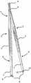
图1以透视图示出成打开状态的根据本发明的(微)外科手持式器械的第一实施方案,所述(微)外科手持式器械包括尚未预弯曲的片状弹簧部分(半成品零件),Figure 1 shows a first embodiment of a (micro)surgical hand-held instrument according to the invention in an open state in a perspective view, said (micro)surgical hand-held instrument comprising a leaf spring part (semi-finished part) which is not yet pre-bent ,
图2以不同透视图示出第一实施方案,Figure 2 shows the first embodiment in a different perspective,
图3以放大视图以及以耦接/钩挂状态示出根据图1的片状弹簧部分/弹簧元件的根据本发明的近侧铰链,Figure 3 shows the proximal hinge according to the invention of the leaf spring part/spring element according to Figure 1 in an enlarged view and in a coupled/hooked state,
图4以侧视图示出根据图1的根据本发明的手持式器械,所述手持式器械具有耦接的近侧铰链并呈闭合/致动状态,Fig. 4 shows the hand-held instrument according to the invention according to Fig. 1 in a side view with a coupled proximal hinge and in a closed/actuated state,
图5以放大表示图以及以未钩挂状态(在这种情况下,片状弹簧尚未塑性预弯曲)示出根据图1的根据本发明的弹簧元件的近侧铰链,Fig. 5 shows the proximal hinge of the spring element according to the invention according to Fig. 1 in an enlarged representation and in an unhooked state (in this case the leaf spring has not yet been plastically pre-bent),
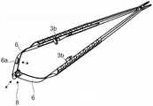
图6以透视表示图示出根据本发明的近侧铰链的另一实施方案,所述近侧铰链包括相对于眼孔轴线倾斜的纵向狭缝以及包括呈展开状态的两个完全杠杆元件(释放远侧铰链),Figure 6 illustrates, in a perspective representation, another embodiment of a proximal hinge according to the invention comprising a longitudinal slit slanted relative to the eyelet axis and comprising two fully lever elements in a deployed state (release distal hinge),
图7以闭合/致动状态示出根据图6的实施方案,Figure 7 shows the embodiment according to Figure 6 in a closed/actuated state,
图8以透视图示出根据图1的(即根据本发明的第一优选实施方案(然而与图1至9形成对比)的)呈成品状态的根据本发明的外科器械,其中两个片状弹簧元件以相对于彼此的弯曲形状(塑性地)预成形,然而近侧铰链是未钩挂的,并且8 shows the surgical instrument according to the present invention in a perspective view according to FIG. 1 , ie according to the first preferred embodiment of the present invention (in contrast to FIGS. 1 to 9 , however) in a finished state, with two sheet-like The spring elements are pre-shaped (plastically) in a curved shape relative to each other, however the proximal hinge is unhooked, and
图9示出根据图8的呈成品状态的根据本发明的外科器械的侧视图,其中近侧铰链是未钩挂的。Figure 9 shows a side view of the surgical instrument according to the invention according to Figure 8 in its finished state, wherein the proximal hinge is unhooked.
图式并不是按真实比例。对所有实施方案来说,相等或同等作用的元件提供有相同参考数字,除非有相反描述。The drawings are not to true scale. Equal or equivalently acting elements are provided with the same reference numerals for all embodiments unless described to the contrary.
具体实施方式Detailed ways
在下文应借助于图1至9来解释根据本发明的耦接机构(也称为闭合机构),所述耦接机构用于有弹力地耦接优选地具有钳子设计或剪刀设计的(微)外科手持式器械的致动杠杆/器械手柄,以便由所述(微)外科手持式器械的分支部分形成的钳口孔口以有弹力地弹性方式打开。The coupling mechanism (also referred to as closing mechanism) according to the invention for elastically coupling (micro) preferably of pliers design or scissors design shall be explained below with the aid of FIGS. 1 to 9 . The actuating lever/instrument handle of a surgical hand-held instrument so that the jaw apertures formed by the branch portions of the (micro)surgical hand-held instrument open in a resiliently resilient manner.
在图1中,例示了具有钳子/剪刀设计的外科手持式器械1,其具有两个杠杆元件2,所述杠杆元件通过接头/远侧铰链5可旋转地/枢转地互连。杠杆元件2中的每一个包括近侧夹持部分(器械手柄)3和远侧分支或钳口部分4(钳口零件)。接头/远侧铰链5被提供在夹持部分3与钳口部分4之间,以便在绕远侧铰链5致动(朝向彼此移动)杠杆元件2的(整体)夹持部分3时,产生远侧钳口部分4的钳子类型或剪刀类型闭合移动。从技术现状充分已知所述钳子-剪刀机构,以便在这一点上免除详细功能描述。In FIG. 1 , a surgical hand-held instrument 1 with a forceps/scissors design is illustrated having two
为提供在没有由钳口部分4施加的夹紧力的(打开和保持分开)位置中保持杠杆元件2的选择,通过相应(片状)弹簧6在近侧方向上使两个夹持部分3在它的自由末端成延伸。每一弹簧6优选地是金属片,尤其由弹簧钢制成,所述金属片可相对容易地并且有弹力地弯曲达足够程度,并且在杠杆元件2的方向上观察时可为扭转的。每一金属板6实质上同轴地延伸至相应杠杆类型夹持部分3并且固定地连接或可固定地连接至所述相应杠杆类型夹持部分。例如,每一金属片6是端对端焊接、熔接、螺纹连接的或甚至由一种材料与相关夹持部分整体形成。To provide the option of holding the
在这种情形下应指出,根据图1以及根据其他图2至7的两个片状弹簧部分6被示出为最初笔直的,因此,仍呈半成品状态。在图8和9中,两个片状弹簧部分6是弯曲的,另一方面,即是所述两个片状弹簧部分以弯曲形状塑性地预成形。这就构成了片状弹簧6的成品状态,其中片状弹簧6施加抵消夹持部分3上的手动致动的偏置力,从而促使/维持器械进入打开位置中/呈打开位置。In this context it should be pointed out that the two
根据图1的外科手持式器械1在图2中以不同透视图示出。The surgical hand-held instrument 1 according to FIG. 1 is shown in a different perspective view in FIG. 2 .
根据图1和2,夹持部分3与弹簧部分6之间的材料厚度差异和因此对弹簧部分6的弹性柔韧性的印象相对(刚性)夹持部分3来说是明显的。因此,弹簧部分6呈片状弹簧形式,并且因此在一个方向上(在一个平面上)可弹性弯曲,而在与之成法向的平面中,弹簧部分是刚性。因此,弹簧元件6本身可基本上采用引导功能来用于绕与弯曲平面成法向的轴线的枢转移动。According to FIGS. 1 and 2 , the difference in material thickness between the clamping
弹簧部分6被连接至相应夹持部分3的远端处,如已在前文中所描述,其中所述相应夹持部分的另一近端最初为自由的。根据本发明,在弹簧部分6的所述自由近端7处提供铰链接头8,所述铰链接头由相互作用以用于连接两个杠杆元件2和相应地连接弹簧部分6的两个部件组成。铰链接头8的部件将在下文由图3来描述。The
图3例示两个弹簧部分6的末端侧面,在所述弹簧部分的近侧自由末端中的每一个处布置有根据本发明的铰链接头8的部件根据图3的一个上弹簧部分6端接在包括铰链销9的保持器中。具体地说,在一个弹簧部分6的近侧叉形末端处,所述一个弹簧部分形成两个相反轴承块,在所述两个相反轴承块之间,铰链销9被紧密地横向插入至所述一个弹簧部分6的纵向延伸部并且横向插入至弹簧部分6的弯曲平面。FIG. 3 illustrates the end sides of the two
另一(根据图3,下)弹簧部分6因此端接在轴承眼(眼孔)10中,在当前实例中,所述轴承眼包括纵向狭缝11,所述纵向狭缝平行于轴承眼轴线延伸。具体地说,另一弹簧部分6在其近端成弯曲以形成滚轴10,然而所述滚轴不是闭合的,但界定在分支部分的方向上径向打开(即,大体上以不同于滚轴10的最近侧定位角位置的角位置来定位)的间隙或狭缝11。The other (according to Fig. 3, lower)
通过(纵向)狭缝11,铰链销9被径向插入滚轴10中,同时弯曲一个弹簧部分6以便滚轴10包封铰链销9(至少包封所述铰链销的圆的四分之三),并且与旋转移动分开,两个弹簧部分6之间的在滚轴10的径向方向或轴向方向上的任何移动是不可能实施的。同样地,可再次从滚轴10移除铰链销9,而不必从铰链接头移除并存放任何单独的部件。因此,手持式器械的操纵是极为简单的。Through the (longitudinal) slit 11 the
图4以侧视图例示呈闭合/致动状态的根据本发明的钳子器械,其中安装有远侧(剪刀/钳子)铰链。脱离这种闭合状态,随后由两个耦接弹簧部分6的弹簧力再次打开钳子器械同时释放夹持部分3。Figure 4 illustrates in a side view a forceps instrument according to the invention in a closed/actuated state with a distal (scissors/forceps) hinge mounted. Released from this closed state, the forceps instrument is then opened again by the spring force of the two
为更详细说明,图5中示出呈未钩挂状态的铰链接头8。明显地,弹簧部分6随滚轴10朝向其狭缝11移动,并且相应地,弹簧部分6由铰链销9径向推入狭缝11中。在这个实施方案中,狭缝11稍微比铰链销9的直径窄,以便必须利用某一力量在另一弹簧部分6的近端处按压在铰链销9上。这个瓶颈提供的优点在于:在实际操作期间排除铰链接头8的无意释放。然而,在这点上,存在众多替代方案。For a more detailed explanation, the
优选的替代方案提供的是:向铰链销9的周边增加平坦化部分9a(如图5所指示)或将销横截面设计成消除圆形,例如,根据椭圆来设计。在这种情况下,狭缝宽度被选择来以便销仅可在其平坦化部分9a的区域中插入滚轴10中。平坦化部分9a的角位置继而被选择来使得在器械的常用回转角度范围内不遵从狭缝11。以这种方式,可防止销9在外科器械的使用期间滑出。Preferred alternatives offer to add a flattened
如可从图5进一步推断的,标记物(推动按钮)6a、6b被提供在片状弹簧部分6的背向彼此的平坦侧面上、处于片状弹簧6中个每一个的中心纵向部分中。所述标记物6a、6b可在适当时由颜色印刷物或表面修饰物(如粗糙化、肋(rib)等)来产生,并且界定相应压力点。所涉及的事实在于:两个片状弹簧6中仅一个片状弹簧(优选地包括滚轴10的一个片状弹簧)的相应标记物足以实现以下描述的功能。As can be further deduced from FIG. 5 , markers (push buttons) 6a, 6b are provided on the flat sides of the
本发明不限于图1至5中的表示图。尤其,可设想相对于包括狭缝11的滚轴10的配置来说的不同形式。此种替代方案在图6和7中示出。The invention is not limited to the representations in FIGS. 1 to 5 . In particular, different forms with respect to the configuration of the
已在前述图中解释了图6和7中根据本发明的外科手持式器械的主要部件。在根据图6的手持式器械的实施方案中,滚轴10在分支部分4的方向不由轴向狭缝11而打开,这不同于先前的实施方案,但是替代地在相反方向上以狭缝形状打开。此外,狭缝11相对弹簧部分6并相应地相对于纵向滚轴轴线对角地(稍微)倾斜或延伸。这意味着,包括滚轴10的弹簧部分6和/或包括铰链销8的弹簧部分6必须稍微扭转(绕杠杆元件2的纵向轴线稍微扭转),以便将铰链销9插入狭缝11中且因此组装铰链接头8。当随后释放弹簧部分6以再次解除扭转时,铰链销9滑动穿过狭缝11进入滚轴10中。在这种情形下应指出,铰链销9在这种情况下不需要任何平坦化部分并且狭缝宽度可对应于销直径。The main components of the surgical hand-held instrument according to the invention in FIGS. 6 and 7 have been explained in the preceding figures. In the embodiment of the hand-held instrument according to FIG. 6 , the
图7中例示呈闭合状态的根据图6的手持式器械。因此,示出以如下方式适用于所有实施方案的根据本发明的手持式器械的另一特征:The hand-held instrument according to FIG. 6 is illustrated in the closed state in FIG. 7 . Therefore, another feature of the hand-held instrument according to the invention is shown which applies to all embodiments in the following way:
如图所例示,在当前情况下,夹持部分3具有壳体设计,每一夹持部分3在横截面中形成小于半圆的分度圆。壳体形状用于接收本身已知的循环屏障件3b的部件,即,尤其是在一个夹持部分处的凸轮部件和在另一夹持部分处的相互作用连结部件。这种类型的循环屏障件属于大体上已知的现有技术,并且因此在这里不必详细地描述。As exemplified in the figures, in the present case, the
根据本发明,现提供对具有已知设计的所使用循环屏障件调整每一夹持部分3的分度圆,以使得在根据图9的器械的闭合和锁定状态中,在夹持部分3的由两个夹持部分3分度圆形成的区域中形成完整的圆,以及在两个夹持手柄3之间形成余隙3a,所述两个夹持手柄在功能上需要用于当前使用使用的循环屏障件3b的致动。此种具有实质上恒定半径的完整的圆形状对操纵器械来说是表现为有利的,因为闭合和锁定的器械可以任何方式安全地并均匀地绕所述器械的纵向轴线旋转而无需在手指之间倾斜器械。因此,也确保器械钳口部分4可被安全地引导。According to the invention, it is now provided to adjust the index circle of each
在图8和9中,根据本发明的器械是以成品和安装状态来例示,其中也指示循环屏障件3b的两个部件。In Figures 8 and 9, the device according to the invention is exemplified in a finished and installed state, wherein the two parts of the
因此,两个弹簧部分6塑性地变形成弯曲形状以便促使夹持部分3分开。当在耦接近侧铰链8的这个状态中时,两个夹持部分3受按压抵靠彼此,两个片状弹簧元件6经历弹性弯曲/拉伸,同时在近侧铰链8内抵靠彼此回转。在夹持部分3的释放之后,两个片状弹簧元件6促使器械回到其打开位置。当在特定枢轴点上进行手动致动时,循环屏障件3b锁定到位并且因此将器械保持在其闭合位置中。Thus, the two
为将近侧铰链8与根据本发明的第一优选实施方案的非倾斜狭缝11拆开,至少将具有末端侧面滚轴10的一个片状弹簧元件侧向地压入标记物6a的区域中。以这种方式,所述弹簧元件弯曲,因此引起滚轴10开始相对于铰链销9旋转。同时,所述一个片状弹簧元件拉伸并且因此在近侧方向上将压力施加在滚轴10上。To detach the
在界定致动距离处,纵向狭缝11进入到铰链销9的平坦化部分9a的区域内,并且滚轴10在近侧方向上位移到铰链销9上。因此,近侧铰链8被拆开。At the defined actuation distance, the
总之,本发明在以下方面相对技术现状占优:In a word, the present invention is superior to the current state of the art in the following aspects:
在本发明中,两个弹簧部分6的连接/回转耦接通过此种铰链接头8来实现,所述铰链接头可不利用突出突片来进行弹簧末端的连接。In the present invention, the connection/swivel coupling of the two
在实施方案中,铰链8的轴承眼/滚轴10被对角地开槽以便铰链8的销9可通过稍微旋转/扭转至少一个弹簧末端而抽出/插入。在另一实施方案中,铰链的轴承眼/滚轴10被开槽,以便销9必须朝向分支部分沿片状弹簧引导以供释放,其中一个弹簧部分6被弹性地弯曲。销9通过弹簧部分6和正闭合件(滚轴10内的铰链销9)两者的弹簧张力而保持在铰链8的滚轴10中处于所述销的可旋转功能位置中。作为另一实施方案,回转耦接/连接可为卡扣/棘爪连接。In an embodiment, the eye/
总之,本发明涉及一种用于抓握物体的外科手持式器械1,其包括:两个杠杆元件2,每一杠杆元件包括夹持部分3和钳口/分支部分4;杠杆接头5,所述杠杆接头将两个杠杆元件在它们的夹持部分与它们的分支部分之间可旋转地彼此连接,其中两个夹持部分中的每一个由相应弹簧部分6邻接,所述相应弹簧部分用于连接两个夹持部分以使得两个杠杆元件2有弹力地保持在打开位置中。为产生用于外科器械上的弹簧末端的可易于管理和可简洁释放的连接,手持式器械包括在一个弹簧部分的自由末端7处的铰链销9,所述铰链销固定地连接至所述一个弹簧部分;和在另一弹簧部分的自由末端7处的轴承眼10,所述轴承眼固定地连接至所述另一弹簧部分,其中轴承眼具有纵向狭缝11以用于铰链销9径向插入轴承眼10中。In summary, the present invention relates to a surgical hand-held instrument 1 for grasping objects, comprising: two
参考数字reference number
1 手持式器械1 Handheld Instrument
2 杠杆元件2 lever element
3 夹持部分3 clamping part
3a 间隙3a gap
3b 循环屏障件3b Circulation barrier
4 钳口部分4 jaw part
5 杠杆接头/远侧铰链5 lever joint/distal hinge
6 弹簧部分6 spring parts
6a、6b 致动标记/按钮6a, 6b Actuation mark/button
7 弹簧部分的近侧自由末端7 Proximal free end of spring section
8 在近侧弹簧末端处的铰链接头8 Hinge joint at proximal spring end
9 铰链销9 hinge pin
10 滚轴10 rollers
11 狭缝11 slit
Claims (14)
Translated fromChineseApplications Claiming Priority (4)
| Application Number | Priority Date | Filing Date | Title |
|---|---|---|---|
| DE102014102606.3 | 2014-02-27 | ||
| DE102014102606.3ADE102014102606A1 (en) | 2014-02-27 | 2014-02-27 | Microsurgical holding and / or cutting instrument |
| PCT/EP2015/053731WO2015128291A1 (en) | 2014-02-27 | 2015-02-23 | Microsurgical holding and/or cutting instrument |
| CN201580010968.5ACN106061414B (en) | 2014-02-27 | 2015-02-23 | Microsurgical holding and/or cutting instruments |
Related Parent Applications (1)
| Application Number | Title | Priority Date | Filing Date |
|---|---|---|---|
| CN201580010968.5ADivisionCN106061414B (en) | 2014-02-27 | 2015-02-23 | Microsurgical holding and/or cutting instruments |
Publications (2)
| Publication Number | Publication Date |
|---|---|
| CN110151256A CN110151256A (en) | 2019-08-23 |
| CN110151256Btrue CN110151256B (en) | 2022-06-07 |
Family
ID=52595318
Family Applications (2)
| Application Number | Title | Priority Date | Filing Date |
|---|---|---|---|
| CN201580010968.5AActiveCN106061414B (en) | 2014-02-27 | 2015-02-23 | Microsurgical holding and/or cutting instruments |
| CN201910420764.9AActiveCN110151256B (en) | 2014-02-27 | 2015-02-23 | Microsurgical holding and/or cutting instrument |
Family Applications Before (1)
| Application Number | Title | Priority Date | Filing Date |
|---|---|---|---|
| CN201580010968.5AActiveCN106061414B (en) | 2014-02-27 | 2015-02-23 | Microsurgical holding and/or cutting instruments |
Country Status (6)
| Country | Link |
|---|---|
| US (2) | US9888934B2 (en) |
| EP (1) | EP3113699B1 (en) |
| CN (2) | CN106061414B (en) |
| DE (1) | DE102014102606A1 (en) |
| ES (1) | ES2643544T3 (en) |
| WO (1) | WO2015128291A1 (en) |
Families Citing this family (12)
| Publication number | Priority date | Publication date | Assignee | Title |
|---|---|---|---|---|
| JP6532113B2 (en) | 2014-11-03 | 2019-06-19 | オレゴン ヘルス アンド サイエンス ユニバーシティ | Clip and Applicator for Tissue Closure |
| USD818123S1 (en)* | 2016-05-13 | 2018-05-15 | Muhammad Hussain | Dual-end forceps |
| DE102017114260A1 (en)* | 2017-06-27 | 2018-12-27 | Aesculap Ag | Medical hand instrument with cleaning-optimized spring element |
| USD907202S1 (en)* | 2018-01-25 | 2021-01-05 | Scanlan International, Inc. | Surgical instrument handle |
| DE102018112346A1 (en)* | 2018-05-23 | 2019-11-28 | Storz Am Mark Gmbh | Medical instrument |
| DE102018109427A1 (en)* | 2018-04-19 | 2019-10-24 | Aesculap Ag | Clip applicator |
| USD904606S1 (en)* | 2019-02-07 | 2020-12-08 | Aesculap Ag | Surgical hammer |
| DE102019106852A1 (en)* | 2019-03-18 | 2020-09-24 | Aesculap Ag | Process for the simple production of a cleaning-optimized instrument spring |
| US11812966B2 (en) | 2020-04-24 | 2023-11-14 | NeuraMedica Inc. | Clips, appliers, and cartridges |
| JP7627018B2 (en) | 2020-08-26 | 2025-02-05 | 国立大学法人金沢大学 | Medical Instruments |
| DE102021113559A1 (en)* | 2021-05-26 | 2022-12-01 | Aesculap Ag | Medical instrument with cleaning-optimized spring unit |
| EP4572689A1 (en)* | 2023-07-17 | 2025-06-25 | Cilag GmbH International | Surgical instrument with clamp arm and pivot shaft hinge coupling |
Family Cites Families (13)
| Publication number | Priority date | Publication date | Assignee | Title |
|---|---|---|---|---|
| DE661032C (en)* | 1938-06-09 | Franz Timmermans Dr | tweezers | |
| DE144979C (en)* | 1902-10-18 | 1903-10-26 | Hugo Rosenstirn | DETACHABLE FORCEPS WITH DETACHABLE HOOK-JOINT CONNECTION AT THE LEG ENDS |
| DE2919271C2 (en) | 1979-05-12 | 1986-07-03 | Holzhauer und Sutter Medizinisch-technische Geräte und Instrumente GmbH, 7800 Freiburg | Surgical instrument, in particular for medical-technical use |
| US4397312A (en)* | 1981-06-17 | 1983-08-09 | Dittmar & Penn Corp. | Clip applying forceps |
| DE3126578C2 (en) | 1981-07-06 | 1984-08-30 | Josef Heiss Medizintechnik GmbH, 7200 Tuttlingen | Two-legged suturing instrument for use in surgery |
| US5065516A (en)* | 1987-05-11 | 1991-11-19 | Andrew Tool Company | Disassemblable scissors means |
| US5269790A (en)* | 1990-10-16 | 1993-12-14 | Noboru Funatsu | Clip forceps |
| DE4115937A1 (en)* | 1990-11-02 | 1992-05-07 | Tibor Koros | Surgical cutting instrument - has frame to support guide for sliding blade which is actuated by pivoting handle |
| US5658297A (en)* | 1995-03-16 | 1997-08-19 | Crainich; Lawrence | Surgical staple remover |
| EP1222903B1 (en)* | 2001-01-12 | 2005-01-19 | Link Spine Group, Inc. | Surgical instrument for implanting an intervertebral prosthesis |
| DE102009008687A1 (en) | 2009-02-06 | 2010-08-12 | Aesculap Ag | Surgical sliding shaft instrument and sliding shaft |
| TWM380110U (en) | 2009-06-15 | 2010-05-11 | Ming-Huei Cheng | Needle holder with integrated scissors for microsurgery |
| JP4693194B1 (en)* | 2010-10-29 | 2011-06-01 | 正一 中村 | Surgical instruments |
- 2014
- 2014-02-27DEDE102014102606.3Apatent/DE102014102606A1/ennot_activeWithdrawn
- 2015
- 2015-02-23CNCN201580010968.5Apatent/CN106061414B/enactiveActive
- 2015-02-23EPEP15706777.8Apatent/EP3113699B1/enactiveActive
- 2015-02-23CNCN201910420764.9Apatent/CN110151256B/enactiveActive
- 2015-02-23WOPCT/EP2015/053731patent/WO2015128291A1/enactiveApplication Filing
- 2015-02-23USUS15/121,265patent/US9888934B2/enactiveActive
- 2015-02-23ESES15706777.8Tpatent/ES2643544T3/enactiveActive
- 2017
- 2017-09-07USUS15/697,971patent/US10368888B2/enactiveActive
Also Published As
| Publication number | Publication date |
|---|---|
| WO2015128291A1 (en) | 2015-09-03 |
| US20170367721A1 (en) | 2017-12-28 |
| US20160361079A1 (en) | 2016-12-15 |
| ES2643544T3 (en) | 2017-11-23 |
| DE102014102606A1 (en) | 2015-08-27 |
| CN106061414A (en) | 2016-10-26 |
| US9888934B2 (en) | 2018-02-13 |
| CN106061414B (en) | 2019-06-14 |
| US10368888B2 (en) | 2019-08-06 |
| CN110151256A (en) | 2019-08-23 |
| EP3113699A1 (en) | 2017-01-11 |
| EP3113699B1 (en) | 2017-08-16 |
Similar Documents
| Publication | Publication Date | Title |
|---|---|---|
| CN110151256B (en) | Microsurgical holding and/or cutting instrument | |
| JP7257519B2 (en) | implant extractor | |
| EP3420976B1 (en) | Endoscopic surgical clip applier including counter assembly | |
| EP3664723B1 (en) | Endoscopic surgical clip applier including counter assembly | |
| EP2147638B1 (en) | Endoscopically inserting surgical tool | |
| DK176344B1 (en) | Endoscopic grip instrument | |
| US7842045B2 (en) | Single fire vascular clip applier with disposable jaw | |
| US9510824B2 (en) | Low profile medical device and related methods of use | |
| EP2042109A1 (en) | Clip applier | |
| JP4242614B2 (en) | Biological tissue ligation device | |
| CN117883143A (en) | Medical device for hemostasis or closure of tissue | |
| CN108601586A (en) | Medical instrument | |
| US20110046661A1 (en) | Surgical instrument which can be disassembled | |
| CN118203385A (en) | Clip applier | |
| US20100298864A1 (en) | Articulating rigid grasper | |
| JP2013514817A (en) | Speculum | |
| WO2015050896A1 (en) | Nerve coupler | |
| US8419720B1 (en) | Flexible laparoscopic device | |
| CN109864772A (en) | Microsurgical instruments and improvements in handles | |
| PL239734B1 (en) | Laparoscopic instrument | |
| US20140288380A1 (en) | Iris retractor assemblies | |
| CN110090065B (en) | Chuck release pincers | |
| KR20030026307A (en) | Clamp for medical use comprising two articulated jaws | |
| CN113616278B (en) | Endoscope clamp capable of being bent | |
| US8672961B2 (en) | Surgical severing instrument |
Legal Events
| Date | Code | Title | Description |
|---|---|---|---|
| PB01 | Publication | ||
| PB01 | Publication | ||
| SE01 | Entry into force of request for substantive examination | ||
| SE01 | Entry into force of request for substantive examination | ||
| GR01 | Patent grant | ||
| GR01 | Patent grant |