CN110137868B - Tank chain device with power supply function - Google Patents
Tank chain device with power supply functionDownload PDFInfo
- Publication number
- CN110137868B CN110137868BCN201910379363.3ACN201910379363ACN110137868BCN 110137868 BCN110137868 BCN 110137868BCN 201910379363 ACN201910379363 ACN 201910379363ACN 110137868 BCN110137868 BCN 110137868B
- Authority
- CN
- China
- Prior art keywords
- power supply
- channel
- chain link
- arc
- chain
- Prior art date
- Legal status (The legal status is an assumption and is not a legal conclusion. Google has not performed a legal analysis and makes no representation as to the accuracy of the status listed.)
- Active
Links
Images


Classifications
- H—ELECTRICITY
- H02—GENERATION; CONVERSION OR DISTRIBUTION OF ELECTRIC POWER
- H02G—INSTALLATION OF ELECTRIC CABLES OR LINES, OR OF COMBINED OPTICAL AND ELECTRIC CABLES OR LINES
- H02G11/00—Arrangements of electric cables or lines between relatively-movable parts
- H02G11/006—Arrangements of electric cables or lines between relatively-movable parts using extensible carrier for the cable, e.g. self-coiling spring
- H—ELECTRICITY
- H01—ELECTRIC ELEMENTS
- H01R—ELECTRICALLY-CONDUCTIVE CONNECTIONS; STRUCTURAL ASSOCIATIONS OF A PLURALITY OF MUTUALLY-INSULATED ELECTRICAL CONNECTING ELEMENTS; COUPLING DEVICES; CURRENT COLLECTORS
- H01R11/00—Individual connecting elements providing two or more spaced connecting locations for conductive members which are, or may be, thereby interconnected, e.g. end pieces for wires or cables supported by the wire or cable and having means for facilitating electrical connection to some other wire, terminal, or conductive member, blocks of binding posts
- H01R11/01—Individual connecting elements providing two or more spaced connecting locations for conductive members which are, or may be, thereby interconnected, e.g. end pieces for wires or cables supported by the wire or cable and having means for facilitating electrical connection to some other wire, terminal, or conductive member, blocks of binding posts characterised by the form or arrangement of the conductive interconnection between the connecting locations
- H—ELECTRICITY
- H02—GENERATION; CONVERSION OR DISTRIBUTION OF ELECTRIC POWER
- H02G—INSTALLATION OF ELECTRIC CABLES OR LINES, OR OF COMBINED OPTICAL AND ELECTRIC CABLES OR LINES
- H02G3/00—Installations of electric cables or lines or protective tubing therefor in or on buildings, equivalent structures or vehicles
- H02G3/02—Details
- H02G3/04—Protective tubing or conduits, e.g. cable ladders or cable troughs
- H02G3/0406—Details thereof
- H—ELECTRICITY
- H02—GENERATION; CONVERSION OR DISTRIBUTION OF ELECTRIC POWER
- H02G—INSTALLATION OF ELECTRIC CABLES OR LINES, OR OF COMBINED OPTICAL AND ELECTRIC CABLES OR LINES
- H02G3/00—Installations of electric cables or lines or protective tubing therefor in or on buildings, equivalent structures or vehicles
- H02G3/02—Details
- H02G3/04—Protective tubing or conduits, e.g. cable ladders or cable troughs
- H02G3/0437—Channels
Landscapes
- Engineering & Computer Science (AREA)
- Architecture (AREA)
- Civil Engineering (AREA)
- Structural Engineering (AREA)
- Details Of Connecting Devices For Male And Female Coupling (AREA)
- Current-Collector Devices For Electrically Propelled Vehicles (AREA)
- Charge And Discharge Circuits For Batteries Or The Like (AREA)
Abstract
Translated fromChinese
Description
Translated fromChinese技术领域technical field
本发明涉及服务器领域,具体地说是一种带有供电功能的坦克链装置。The invention relates to the field of servers, in particular to a tank chain device with a power supply function.
背景技术Background technique
目前在服务器系统中,对大功率供电和可维护性需要越来越强烈,目前很多设备在供电方式上会用到大电流的铜排供电方式,另一方面为了方便设备维护,在理线方式上会采用坦克链的方式来做板卡与板卡之间,板卡与设备之间的线缆理线方式,一般坦克链内部用于混装强电和弱电,导致信号输出不稳定,存在干扰,且强电也会占据一定坦克链空间,降低了坦克链内信号线的数量或者导致使用大体积的坦克链,不美观,成本高。At present, in the server system, the need for high-power power supply and maintainability is becoming more and more intense. At present, many devices use the high-current copper-bar power supply mode in the power supply mode. The tank chain method will be used to organize the cables between the board and the board, and between the board and the device. Generally, the tank chain is used to mix strong and weak currents, resulting in unstable signal output. Interference, and strong electricity will also occupy a certain tank chain space, reducing the number of signal lines in the tank chain or causing the use of large-volume tank chains, which is unsightly and costly.
发明内容SUMMARY OF THE INVENTION
针对目前坦克链理线过程中存在的强电弱电混装导致信号输出不稳定的问题,本发明提供一种带有供电功能的坦克链装置,可以避免上述问题的发生。Aiming at the problem of unstable signal output caused by the mixed installation of strong and weak currents in the current tank chain wiring process, the present invention provides a tank chain device with a power supply function, which can avoid the occurrence of the above problems.
本发明解决其技术问题所采取的技术方案是:The technical scheme adopted by the present invention to solve its technical problems is:
一种带有供电功能的坦克链装置,包括链节,所述链节包括底板,所述底板两侧各设有一侧板,所述侧板上设有卡槽,所述卡槽内安装有卡板,在链节上设有安装孔和安装柱,所述链节的侧板两侧均设有导电层,所述导电层上侧贴敷有绝缘层。利用链节两端设有导电层的设计,实现利用坦克链供电的技术效果,通过装配工艺完全可以实现,在降低成本的同时,避免强电对弱电造成影响,提高产品的可靠性。在该处,导电层周围包裹有一层绝缘层,将导电层贴在侧板也完全可以实现类似技术效果。上述等效代替均在本案的保护范围之内。A tank chain device with a power supply function includes a chain link, the chain link includes a bottom plate, each side of the bottom plate is provided with a side plate, the side plate is provided with a card slot, and a card slot is installed in the card slot. The card board is provided with mounting holes and mounting posts on the chain links, conductive layers are provided on both sides of the side plates of the chain links, and an insulating layer is applied on the upper side of the conductive layers. Using the design of the conductive layer at both ends of the chain link, the technical effect of using the tank chain for power supply can be achieved, which can be completely achieved through the assembly process. While reducing the cost, it can avoid the impact of strong electricity on weak electricity and improve the reliability of the product. Here, an insulating layer is wrapped around the conductive layer, and a similar technical effect can be achieved by attaching the conductive layer to the side plate. The above-mentioned equivalent substitutions are all within the protection scope of this case.
进一步地,所述导电层包括直导电柱、弧形连接柱、中间导电柱及弧形导电板,所述绝缘层内设有安装槽,所述安装槽内顺次安装有直导电柱、弧形连接柱、中间导电柱、弧形导电板。利用安装槽的设计,实现导电模块被完全隐藏在链节之内,提高安全可靠系数。Further, the conductive layer includes a straight conductive column, an arc-shaped connecting column, an intermediate conductive column and an arc-shaped conductive plate, and an installation groove is arranged in the insulating layer, and the straight conductive column and the arc-shaped conductive plate are sequentially installed in the installation groove. shape connecting column, middle conductive column, arc conductive plate. Using the design of the installation slot, the conductive module is completely hidden in the chain link, and the safety and reliability factor is improved.
进一步地,所述弧形导电板的形状与侧板边缘相配合。Further, the shape of the arc-shaped conductive plate is matched with the edge of the side plate.
进一步地,所述安装槽包括第一通道、调节腔、弧形通道、端部通道及外弧型口,其中第一通道、调节腔、弧形通道、端部通道及外弧型口彼此顺次相连,在调节腔内安装有第一弹簧与第二弹簧,其中第一弹簧上连接有第一轮,第二弹簧上连接有第二轮,直导电柱从第一通道进入安装槽,绕过第一轮、第二轮后从端部通道穿出。利用直导电柱的长度伸缩设计,避免链节转动时的干扰。Further, the installation groove includes a first channel, an adjustment cavity, an arc-shaped channel, an end channel and an outer arc-shaped opening, wherein the first channel, the adjustment cavity, the arc-shaped channel, the end channel and the outer arc-shaped opening are in line with each other. The first spring and the second spring are installed in the adjustment cavity. The first spring is connected with the first wheel, and the second spring is connected with the second wheel. The straight conductive column enters the installation slot from the first channel and goes around the After passing through the first and second rounds, it passes through the end channel. The length expansion and contraction design of the straight conductive column is used to avoid the interference when the chain link rotates.
进一步地,所述导电层采用导体材料。Further, the conductive layer adopts a conductor material.
进一步地,所述链节一侧导电层所形成的导电通路作为供电,另一侧导电通路作为地回流,在坦克链两端增加供电连接器分别与供电源端和吃电端板卡连接。Further, the conductive path formed by the conductive layer on one side of the chain link is used as power supply, and the conductive path on the other side is used as ground return flow.
本发明的有益效果是:本发明利用坦克链自有特性结合实际实现了强电弱电分离,完美解决了现有技术中存在的问题,还降低使用成本,减少供电线的使用,更加美观,成品得以小型化。The beneficial effects of the present invention are as follows: the present invention utilizes the inherent characteristics of the tank chain to realize the separation of strong and weak currents, perfectly solves the problems existing in the prior art, also reduces the use cost, reduces the use of power supply lines, is more beautiful, and the finished product is more beautiful. be miniaturized.
附图说明Description of drawings
图1为现有坦克链的三维结构示意图;Fig. 1 is the three-dimensional structure schematic diagram of the existing tank chain;
图2为链节的三维结构示意图;Fig. 2 is the three-dimensional structure schematic diagram of chain link;
图3为本发明第一实施例的剖视图;3 is a cross-sectional view of the first embodiment of the present invention;
图4为本发明第二实施例的剖视图;4 is a cross-sectional view of a second embodiment of the present invention;
图5为本发明第三实施例的剖视图;5 is a cross-sectional view of a third embodiment of the present invention;
图6为本发明第四实施例的剖视图;6 is a cross-sectional view of a fourth embodiment of the present invention;
图中:1 链节,11底板,12侧板,121安装孔,122安装柱,123卡槽,2固定节,3移动节,4卡板,5导电层,6绝缘层,61安装槽,71直导电柱,72弧形连接柱,73中间导电柱,74弧形导电板,82第一弹簧,83第一轮,84第二弹簧, 85第二轮。In the picture: 1 chain link, 11 bottom plate, 12 side plate, 121 mounting hole, 122 mounting post, 123 card slot, 2 fixed link, 3 movable link, 4 card plate, 5 conductive layer, 6 insulating layer, 61 mounting slot, 71 straight conductive column, 72 arc connection column, 73 middle conductive column, 74 arc conductive plate, 82 first spring, 83 first wheel, 84 second spring, 85 second wheel.
具体实施方式Detailed ways
如图1至图2所示,现在坦克链一般包括有固定节2、移动节3,两者之间通过一连串的链节1首尾相接而成。As shown in Figures 1 to 2, now the tank chain generally includes a fixed section 2 and a
所述链节包括底板11,所述底板两侧各设有一侧板12,所述侧板上设有卡槽123,所述卡槽内安装有卡板4。数据线、信号线等等放置在底板、侧板及卡板围成的腔体内。The chain link includes a
在链节上设有安装孔121和安装柱122,本链节的安装柱用于安装在相邻链节的安装孔内。同理,本链节的安装孔安装有另一链节的安装柱。A
该带有供电功能的坦克链装置,包括链节1,两块所述链节的侧板上均设有导电层5,所述导电层上侧贴敷有绝缘层6,导电层5采用导体材料,链节一侧导电层5所形成的导电通路作为供电,另一侧导电通路作为地回流,在坦克链两端增加供电连接器或其他连接装置,分别与供电源端和吃电端板卡或设备连接。The tank chain device with power supply function includes a
在这种情况下,坦克链一方面提供机箱内理线的功能,另一方面,在坦克链两端增加导电通路连接在电源端与需要供电的板卡端,这样在实现坦克链理线的基础上可以同步实现供电的功能。In this case, on the one hand, the tank chain provides the function of cable management in the chassis. On the basis, the function of power supply can be realized synchronously.
方案优化设计,如图4所示,两块所述链节的侧板上均设绝缘层6,所述绝缘层内设有安装槽61,所述安装槽内顺次安装有直导电柱71、弧形连接柱72、中间导电柱73、弧形导电板74,其中直导电柱连接有弧形连接柱,弧形连接柱连接有中间导电柱,中间导电柱连接在弧形导电板的中部,其中直导电柱与另一链节上的弧形导电板相接触,以保证通电的连续性。In the optimized design of the scheme, as shown in FIG. 4 , an
所述弧形导电板的形状与侧板边缘相配合。The shape of the arc conductive plate is matched with the edge of the side plate.
该安装槽内还可放置有一完整的直导电柱71。如图6所示,其中安装槽直径需大于直导电柱的直径,两者之间存在一定间隙,使得链节在转动一定角度时,避免直导电柱拉扯过度造成链节无法转动。A complete straight
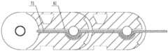
进一步优化设计,所述安装槽包括第一通道62、调节腔63、弧形通道64、端部通道65及外弧型口66,其中第一通道62、调节腔63、弧形通道64、端部通道65及外弧型口66彼此顺次相连。Further optimized design, the installation groove includes a
在调节腔内安装有第一弹簧82与第二弹簧84,其中第一弹簧上连接有第一轮83,第二弹簧上连接有第二轮85,直导电柱从第一通道进入安装槽,绕过第一轮、第二轮后从端部通道穿出,可后续再穿入另一链节的安装槽内。A
这种设计,利用链节将强电弱电分离,避免强电干扰,还利用坦克链实现供电功能。In this design, the chain links are used to separate the strong and weak electricity to avoid strong electric interference, and the tank chain is also used to realize the power supply function.
除说明书所述的技术特征外,均为本专业技术人员的已知技术。Except for the technical features described in the specification, they are all known technologies by those skilled in the art.
Claims (2)
Translated fromChinesePriority Applications (3)
| Application Number | Priority Date | Filing Date | Title |
|---|---|---|---|
| CN201910379363.3ACN110137868B (en) | 2019-05-08 | 2019-05-08 | Tank chain device with power supply function |
| US17/281,262US11309696B2 (en) | 2019-05-08 | 2019-08-30 | Cable carrier apparatus with power supply function |
| PCT/CN2019/103723WO2020224129A1 (en) | 2019-05-08 | 2019-08-30 | Cable carrier apparatus with power supply function |
Applications Claiming Priority (1)
| Application Number | Priority Date | Filing Date | Title |
|---|---|---|---|
| CN201910379363.3ACN110137868B (en) | 2019-05-08 | 2019-05-08 | Tank chain device with power supply function |
Publications (2)
| Publication Number | Publication Date |
|---|---|
| CN110137868A CN110137868A (en) | 2019-08-16 |
| CN110137868Btrue CN110137868B (en) | 2020-07-07 |
Family
ID=67576626
Family Applications (1)
| Application Number | Title | Priority Date | Filing Date |
|---|---|---|---|
| CN201910379363.3AActiveCN110137868B (en) | 2019-05-08 | 2019-05-08 | Tank chain device with power supply function |
Country Status (3)
| Country | Link |
|---|---|
| US (1) | US11309696B2 (en) |
| CN (1) | CN110137868B (en) |
| WO (1) | WO2020224129A1 (en) |
Families Citing this family (4)
| Publication number | Priority date | Publication date | Assignee | Title |
|---|---|---|---|---|
| CN110137868B (en)* | 2019-05-08 | 2020-07-07 | 苏州浪潮智能科技有限公司 | Tank chain device with power supply function |
| US11396925B2 (en)* | 2020-02-11 | 2022-07-26 | Dell Products L.P. | Cable chain for use in cable management |
| US12135070B2 (en)* | 2020-05-27 | 2024-11-05 | Igus Gmbh | Energy guide chain with flexible joint connectors as well as side plates and joint connectors for same |
| CN115234176B (en)* | 2022-09-21 | 2022-12-13 | 无锡市安曼工程机械有限公司 | Modularization rope winding mechanism |
Family Cites Families (72)
| Publication number | Priority date | Publication date | Assignee | Title |
|---|---|---|---|---|
| US616672A (en)* | 1898-12-27 | kelling | ||
| US680328A (en)* | 1900-09-11 | 1901-08-13 | Sheffield Car Co | Stand-pipe. |
| US1347470A (en)* | 1915-08-06 | 1920-07-20 | Francis N Bard | Gasket for flexible joints |
| US1475090A (en)* | 1922-06-19 | 1923-11-20 | Lynchburg Foundry Company | Flexible pipe joint |
| US2564938A (en)* | 1945-05-21 | 1951-08-21 | Charles F Warren | Flexible pipe joint |
| US2850299A (en)* | 1953-09-22 | 1958-09-02 | Dresser Ind | Flexible insulating coupling for threaded pipe |
| US3030130A (en)* | 1958-06-16 | 1962-04-17 | Arthur I Appleton | Fitting for flexible conduit |
| DE1131480B (en)* | 1961-02-08 | 1962-06-14 | Kabelschlepp Gmbh | Link chain for guiding electrical cables or the like. |
| US3139115A (en)* | 1963-03-18 | 1964-06-30 | Dore Co John L | Lined vacuum bellows |
| US3330105A (en)* | 1965-06-23 | 1967-07-11 | Maysteel Products Corp | Protective device for flexible conductors |
| US3770022A (en)* | 1970-07-31 | 1973-11-06 | Konings P Maschf | Support devices for elongate members |
| US3650550A (en)* | 1970-08-13 | 1972-03-21 | Dow Chemical Co | Lined conduit |
| DE2255283C3 (en)* | 1972-11-11 | 1975-06-05 | Kabelschlepp Gmbh, 5900 Siegen | Energy chain |
| DE2360227C3 (en)* | 1973-12-04 | 1981-08-20 | Kabelschlepp Gmbh, 5900 Siegen | Energy chain |
| GB1497107A (en)* | 1975-10-13 | 1978-01-05 | Uniroyal Ltd | Expansion joints and dredging sleeves |
| DE2622006B2 (en)* | 1976-05-18 | 1978-03-16 | Kabelschlepp Gmbh, 5900 Siegen | Energy chain |
| JPS5727992Y2 (en)* | 1978-04-18 | 1982-06-18 | ||
| DE2934916C2 (en)* | 1979-08-29 | 1983-12-01 | Volker O. Prof. Dr.Med. 8012 Ottobrunn Lang | Universal sterile closed tube SETS for artificial ventilation, auxiliary breathing and aerosol therapy |
| EP0038952B1 (en)* | 1980-04-30 | 1984-05-16 | Kabelschlepp Gesellschaft mit beschränkter Haftung | Energy line support |
| US4625936A (en)* | 1983-06-06 | 1986-12-02 | Sine Products Company | Flexible support and carrier assembly |
| DE3445493A1 (en)* | 1984-12-13 | 1986-06-26 | Witzenmann GmbH, Metallschlauch-Fabrik Pforzheim, 7530 Pforzheim | FLEXIBLE HOSE WITH RECTANGULAR SECTION, IN PARTICULAR ENERGY PIPE SUPPORT |
| US5463187A (en)* | 1992-09-30 | 1995-10-31 | The George Ingraham Corp. | Flexible multi-duct conduit assembly |
| US5992896A (en)* | 1995-12-08 | 1999-11-30 | Senior Engineering Investments Ag | Flexible coupler apparatus |
| DE19710489A1 (en)* | 1997-03-13 | 1998-09-24 | Kabelschlepp Gmbh | Foldable protective element for cables |
| GB9724402D0 (en)* | 1997-11-19 | 1998-01-14 | Mansign Mining Equipment Ltd | Cable/hose handling chain |
| JP3157491B2 (en)* | 1997-11-28 | 2001-04-16 | 株式会社椿本チエイン | Flexible guide support chain |
| DE19815137B4 (en)* | 1998-04-03 | 2004-04-29 | Fränkische Rohrwerke Gebr. Kirchner GmbH & Co | pipe arrangement |
| DE19839270C2 (en)* | 1998-05-05 | 2000-10-26 | Igus Gmbh | Energy chain |
| US6311736B2 (en)* | 1998-05-28 | 2001-11-06 | Donaldson Company, Inc. | Flexible hose and method for manufacturing |
| DE19837231A1 (en)* | 1998-08-17 | 2000-02-24 | Kabelschlepp Gmbh | Conductor guide arrangement for connection of movable load, has conductor recording channel subdivided through cross separations several flexible segments |
| DE19962829A1 (en)* | 1999-12-23 | 2001-08-23 | Kabelschlepp Gmbh | Strand and method for producing a fiber-reinforced strand of a cable routing arrangement |
| DE20002820U1 (en)* | 2000-02-16 | 2000-05-25 | Igus Spritzgußteile für die Industrie GmbH, 51147 Köln | Energy chain |
| US6837846B2 (en)* | 2000-04-03 | 2005-01-04 | Neo Guide Systems, Inc. | Endoscope having a guide tube |
| JP3356754B2 (en)* | 2000-05-01 | 2002-12-16 | 株式会社椿本チエイン | Flexible support and guide device for cables |
| JP2001343146A (en)* | 2000-06-02 | 2001-12-14 | Totaku Kogyo Kk | Incombustible heat insulating duct |
| US20010054820A1 (en)* | 2000-06-19 | 2001-12-27 | Starita Joseph M. | Corrugated plastic pipe sections having flanged ends and structurally tight joints thereof |
| CA2338814C (en)* | 2001-02-27 | 2009-09-15 | Canplas Industries Ltd. | P-trap for plumbing drainage systems |
| EP1241054B1 (en)* | 2001-03-16 | 2005-09-14 | Yazaki Corporation | Wiring harness arrangement assembly for sliding door of car |
| US6854768B2 (en)* | 2001-04-26 | 2005-02-15 | Innatech, Llc | Fluid conduits and method of manufacturing same |
| JP3349146B1 (en)* | 2001-09-06 | 2002-11-20 | 株式会社椿本チエイン | Cable protection guide |
| US6648376B2 (en)* | 2002-03-29 | 2003-11-18 | Showertek, Inc. | Flexible sectioned arm with internal overbending-prevention sleeves |
| US6715799B2 (en)* | 2002-04-16 | 2004-04-06 | David J. Hardy | Corrugated pipe coupling having six degrees of freedom |
| US7270198B2 (en)* | 2002-12-09 | 2007-09-18 | American Kinetics, Inc. | Orienter for drilling tool assembly and method |
| JP2005046829A (en)* | 2003-07-11 | 2005-02-24 | Suikosha:Kk | Nebulizer |
| US20050038318A1 (en)* | 2003-08-13 | 2005-02-17 | Benad Goldwasser | Gastrointestinal tool over guidewire |
| US7533906B2 (en)* | 2003-10-14 | 2009-05-19 | Water Pik, Inc. | Rotatable and pivotable connector |
| DE202004005848U1 (en)* | 2003-10-15 | 2005-02-24 | Igus Spritzgussteile für die Industrie GmbH | Line guiding arrangement comprises units with a base part and side walls made from rigid U-profiles |
| DE202004005800U1 (en) | 2004-04-08 | 2005-08-25 | Igus Gmbh | Power supply chain |
| GB0408944D0 (en)* | 2004-04-22 | 2004-05-26 | Hydrasun Ltd | Support apparatus and method |
| US7837615B2 (en)* | 2004-05-10 | 2010-11-23 | Usgi Medical, Inc. | Shape lockable apparatus and method for advancing an instrument through unsupported anatomy |
| FR2875065A1 (en)* | 2004-09-03 | 2006-03-10 | Valeo Electronique Sys Liaison | Flat electrical conductor supporting and guiding device for motor vehicle, has chain formed with links to receive sheet, where each link has bar integrated to edge of one flange end and extending till right of related edge of another flange |
| JP4111967B2 (en)* | 2005-09-29 | 2008-07-02 | 株式会社椿本チエイン | Cable protection guide device |
| JP5052073B2 (en)* | 2006-09-04 | 2012-10-17 | 株式会社椿本チエイン | Cable protection guide device |
| US7469722B2 (en)* | 2006-12-19 | 2008-12-30 | Norvald Berland | Segmented bend stiffener |
| US8047236B2 (en)* | 2008-09-12 | 2011-11-01 | Boston Scientific Scimed, Inc. | Flexible conduit with locking element |
| US8388520B2 (en)* | 2009-02-25 | 2013-03-05 | Ethicon Endo-Surgery, Inc. | Shape control endoscope |
| ES2456354T3 (en)* | 2009-08-05 | 2014-04-22 | Prysmian S.P.A. | Flat power cable |
| US8622481B2 (en)* | 2011-01-25 | 2014-01-07 | Joy Mm Delaware, Inc. | Fiber optic cable protection in a mining system |
| WO2012106185A1 (en)* | 2011-01-31 | 2012-08-09 | Boston Scientific Scimed, Inc. | Articulation section with locking |
| DE202011004762U1 (en)* | 2011-04-04 | 2011-09-07 | Igus Gmbh | Power supply chain |
| JP2012223057A (en)* | 2011-04-13 | 2012-11-12 | Sumitomo Wiring Syst Ltd | Distribution structure of wire harness |
| GB201122436D0 (en)* | 2011-12-29 | 2012-02-08 | Wellstream Int Ltd | Flexible pipe body and method of manufacture |
| US9408606B2 (en)* | 2012-06-28 | 2016-08-09 | Ethicon Endo-Surgery, Llc | Robotically powered surgical device with manually-actuatable reversing system |
| US9810349B2 (en)* | 2014-10-21 | 2017-11-07 | James M. Lee | Modular conduit system |
| US10980538B2 (en)* | 2015-08-26 | 2021-04-20 | Ethicon Llc | Surgical stapling configurations for curved and circular stapling instruments |
| JP6233723B2 (en)* | 2015-09-09 | 2017-11-22 | 住友電装株式会社 | Electric wire guide device |
| CN206147374U (en)* | 2016-07-06 | 2017-05-03 | 浪潮电子信息产业股份有限公司 | Improved generation tank chain reason line structure |
| US10295689B2 (en)* | 2016-10-03 | 2019-05-21 | Sercel, Inc. | Controlled curvature bend device and method |
| EP3574249A4 (en)* | 2017-01-25 | 2021-01-06 | Whitefield Plastics Corporation | Non-metallic clip connection system, vertebrae bend restrictor, and vertebrae end piece |
| JP6640255B2 (en)* | 2018-02-20 | 2020-02-05 | 矢崎総業株式会社 | Bending control member and power supply device |
| CN110137868B (en)* | 2019-05-08 | 2020-07-07 | 苏州浪潮智能科技有限公司 | Tank chain device with power supply function |
| IT202000011653A1 (en)* | 2020-05-20 | 2021-11-20 | Prysmian Spa | APPARATUS AND METHOD FOR TESTING A HIGH VOLTAGE SUBMARINE CABLE SYSTEM |
- 2019
- 2019-05-08CNCN201910379363.3Apatent/CN110137868B/enactiveActive
- 2019-08-30WOPCT/CN2019/103723patent/WO2020224129A1/ennot_activeCeased
- 2019-08-30USUS17/281,262patent/US11309696B2/enactiveActive
Also Published As
| Publication number | Publication date |
|---|---|
| US20220006278A1 (en) | 2022-01-06 |
| US11309696B2 (en) | 2022-04-19 |
| WO2020224129A1 (en) | 2020-11-12 |
| CN110137868A (en) | 2019-08-16 |
Similar Documents
| Publication | Publication Date | Title |
|---|---|---|
| CN110137868B (en) | Tank chain device with power supply function | |
| US10992254B2 (en) | Lead assembly for connecting solar panel arrays to inverter | |
| TW200742294A (en) | Transmission device and communication production employing the same | |
| CN101438171A (en) | Lumped resistance electrical cable | |
| CN109755840B (en) | Assembling method of plug connector assembly | |
| CN101814334A (en) | Double-layer conductor flat flexible line | |
| CN102570219A (en) | Wiring board and socket used together with same | |
| CN100590938C (en) | A power connection device with a guide rail | |
| US20130062115A1 (en) | Outdoor control cable | |
| US8692113B2 (en) | Connector assembly | |
| KR20160014694A (en) | Power supply assembly intended to recharge electric batteries for electric motor vehicles | |
| CN203562536U (en) | Lead structure used for PCB terminal | |
| CN203942064U (en) | Sleeve | |
| CN104466877B (en) | A kind of safe and efficient connecting box of display with voltage | |
| CN209344366U (en) | A low-voltage cable connector | |
| CN202142333U (en) | Redundant large-current power supply cable assembly | |
| CN219371618U (en) | High-altitude cold-resistant photovoltaic cable | |
| CN1996680A (en) | Bus connector | |
| CN205646459U (en) | Transformer substation and outlet structure thereof | |
| CN223066772U (en) | Junction Box | |
| CN103545625A (en) | High voltage connecting terminal module | |
| CN203617510U (en) | Connecting device, male connector, female connector and unmanned aerial vehicle | |
| CN203786170U (en) | New Composite Terminal Junction Box | |
| CN221282538U (en) | High-speed cable connector | |
| CN216794568U (en) | Bus duct wiring adapter |
Legal Events
| Date | Code | Title | Description |
|---|---|---|---|
| PB01 | Publication | ||
| PB01 | Publication | ||
| SE01 | Entry into force of request for substantive examination | ||
| SE01 | Entry into force of request for substantive examination | ||
| GR01 | Patent grant | ||
| GR01 | Patent grant | ||
| CP03 | Change of name, title or address | Address after:Building 9, No.1, guanpu Road, Guoxiang street, Wuzhong Economic Development Zone, Wuzhong District, Suzhou City, Jiangsu Province Patentee after:Suzhou Yuannao Intelligent Technology Co.,Ltd. Country or region after:China Address before:Building 9, No.1, guanpu Road, Guoxiang street, Wuzhong Economic Development Zone, Wuzhong District, Suzhou City, Jiangsu Province Patentee before:SUZHOU LANGCHAO INTELLIGENT TECHNOLOGY Co.,Ltd. Country or region before:China |