CN110121319B - Distal torque component, delivery system, and method of use thereof - Google Patents
Distal torque component, delivery system, and method of use thereofDownload PDFInfo
- Publication number
- CN110121319B CN110121319BCN201880005338.2ACN201880005338ACN110121319BCN 110121319 BCN110121319 BCN 110121319BCN 201880005338 ACN201880005338 ACN 201880005338ACN 110121319 BCN110121319 BCN 110121319B
- Authority
- CN
- China
- Prior art keywords
- stent
- graft
- delivery system
- arms
- proximal
- Prior art date
- Legal status (The legal status is an assumption and is not a legal conclusion. Google has not performed a legal analysis and makes no representation as to the accuracy of the status listed.)
- Active
Links
Images


Classifications
- A—HUMAN NECESSITIES
- A61—MEDICAL OR VETERINARY SCIENCE; HYGIENE
- A61F—FILTERS IMPLANTABLE INTO BLOOD VESSELS; PROSTHESES; DEVICES PROVIDING PATENCY TO, OR PREVENTING COLLAPSING OF, TUBULAR STRUCTURES OF THE BODY, e.g. STENTS; ORTHOPAEDIC, NURSING OR CONTRACEPTIVE DEVICES; FOMENTATION; TREATMENT OR PROTECTION OF EYES OR EARS; BANDAGES, DRESSINGS OR ABSORBENT PADS; FIRST-AID KITS
- A61F2/00—Filters implantable into blood vessels; Prostheses, i.e. artificial substitutes or replacements for parts of the body; Appliances for connecting them with the body; Devices providing patency to, or preventing collapsing of, tubular structures of the body, e.g. stents
- A61F2/95—Instruments specially adapted for placement or removal of stents or stent-grafts
- A61F2/962—Instruments specially adapted for placement or removal of stents or stent-grafts having an outer sleeve
- A61F2/966—Instruments specially adapted for placement or removal of stents or stent-grafts having an outer sleeve with relative longitudinal movement between outer sleeve and prosthesis, e.g. using a push rod
- A61F2/9662—Instruments specially adapted for placement or removal of stents or stent-grafts having an outer sleeve with relative longitudinal movement between outer sleeve and prosthesis, e.g. using a push rod the middle portion of the stent or stent-graft is released first
- A—HUMAN NECESSITIES
- A61—MEDICAL OR VETERINARY SCIENCE; HYGIENE
- A61F—FILTERS IMPLANTABLE INTO BLOOD VESSELS; PROSTHESES; DEVICES PROVIDING PATENCY TO, OR PREVENTING COLLAPSING OF, TUBULAR STRUCTURES OF THE BODY, e.g. STENTS; ORTHOPAEDIC, NURSING OR CONTRACEPTIVE DEVICES; FOMENTATION; TREATMENT OR PROTECTION OF EYES OR EARS; BANDAGES, DRESSINGS OR ABSORBENT PADS; FIRST-AID KITS
- A61F2/00—Filters implantable into blood vessels; Prostheses, i.e. artificial substitutes or replacements for parts of the body; Appliances for connecting them with the body; Devices providing patency to, or preventing collapsing of, tubular structures of the body, e.g. stents
- A61F2/95—Instruments specially adapted for placement or removal of stents or stent-grafts
- A61F2/962—Instruments specially adapted for placement or removal of stents or stent-grafts having an outer sleeve
- A61F2/966—Instruments specially adapted for placement or removal of stents or stent-grafts having an outer sleeve with relative longitudinal movement between outer sleeve and prosthesis, e.g. using a push rod
- A—HUMAN NECESSITIES
- A61—MEDICAL OR VETERINARY SCIENCE; HYGIENE
- A61F—FILTERS IMPLANTABLE INTO BLOOD VESSELS; PROSTHESES; DEVICES PROVIDING PATENCY TO, OR PREVENTING COLLAPSING OF, TUBULAR STRUCTURES OF THE BODY, e.g. STENTS; ORTHOPAEDIC, NURSING OR CONTRACEPTIVE DEVICES; FOMENTATION; TREATMENT OR PROTECTION OF EYES OR EARS; BANDAGES, DRESSINGS OR ABSORBENT PADS; FIRST-AID KITS
- A61F2/00—Filters implantable into blood vessels; Prostheses, i.e. artificial substitutes or replacements for parts of the body; Appliances for connecting them with the body; Devices providing patency to, or preventing collapsing of, tubular structures of the body, e.g. stents
- A61F2/02—Prostheses implantable into the body
- A61F2/04—Hollow or tubular parts of organs, e.g. bladders, tracheae, bronchi or bile ducts
- A61F2/06—Blood vessels
- A61F2/07—Stent-grafts
- A—HUMAN NECESSITIES
- A61—MEDICAL OR VETERINARY SCIENCE; HYGIENE
- A61F—FILTERS IMPLANTABLE INTO BLOOD VESSELS; PROSTHESES; DEVICES PROVIDING PATENCY TO, OR PREVENTING COLLAPSING OF, TUBULAR STRUCTURES OF THE BODY, e.g. STENTS; ORTHOPAEDIC, NURSING OR CONTRACEPTIVE DEVICES; FOMENTATION; TREATMENT OR PROTECTION OF EYES OR EARS; BANDAGES, DRESSINGS OR ABSORBENT PADS; FIRST-AID KITS
- A61F2/00—Filters implantable into blood vessels; Prostheses, i.e. artificial substitutes or replacements for parts of the body; Appliances for connecting them with the body; Devices providing patency to, or preventing collapsing of, tubular structures of the body, e.g. stents
- A61F2/95—Instruments specially adapted for placement or removal of stents or stent-grafts
- A61F2/9517—Instruments specially adapted for placement or removal of stents or stent-grafts handle assemblies therefor
- A—HUMAN NECESSITIES
- A61—MEDICAL OR VETERINARY SCIENCE; HYGIENE
- A61F—FILTERS IMPLANTABLE INTO BLOOD VESSELS; PROSTHESES; DEVICES PROVIDING PATENCY TO, OR PREVENTING COLLAPSING OF, TUBULAR STRUCTURES OF THE BODY, e.g. STENTS; ORTHOPAEDIC, NURSING OR CONTRACEPTIVE DEVICES; FOMENTATION; TREATMENT OR PROTECTION OF EYES OR EARS; BANDAGES, DRESSINGS OR ABSORBENT PADS; FIRST-AID KITS
- A61F2/00—Filters implantable into blood vessels; Prostheses, i.e. artificial substitutes or replacements for parts of the body; Appliances for connecting them with the body; Devices providing patency to, or preventing collapsing of, tubular structures of the body, e.g. stents
- A61F2/95—Instruments specially adapted for placement or removal of stents or stent-grafts
- A61F2/962—Instruments specially adapted for placement or removal of stents or stent-grafts having an outer sleeve
- A61F2/966—Instruments specially adapted for placement or removal of stents or stent-grafts having an outer sleeve with relative longitudinal movement between outer sleeve and prosthesis, e.g. using a push rod
- A61F2002/9665—Instruments specially adapted for placement or removal of stents or stent-grafts having an outer sleeve with relative longitudinal movement between outer sleeve and prosthesis, e.g. using a push rod with additional retaining means
Landscapes
- Health & Medical Sciences (AREA)
- Engineering & Computer Science (AREA)
- Biomedical Technology (AREA)
- Cardiology (AREA)
- Oral & Maxillofacial Surgery (AREA)
- Transplantation (AREA)
- Heart & Thoracic Surgery (AREA)
- Vascular Medicine (AREA)
- Life Sciences & Earth Sciences (AREA)
- Animal Behavior & Ethology (AREA)
- General Health & Medical Sciences (AREA)
- Public Health (AREA)
- Veterinary Medicine (AREA)
- Prostheses (AREA)
- Media Introduction/Drainage Providing Device (AREA)
Abstract
Description
Translated fromChinese相关申请related application
本申请要求2017年10月31日提交的美国临时申请No.60/579,482的权益。所述申请的完整教导通过引用合并与此。This application claims the benefit of U.S. Provisional Application No. 60/579,482, filed October 31, 2017. The entire teaching of said application is hereby incorporated by reference.
背景技术Background technique
包括主动脉瘤的动脉病变可通过开放性外科重建进行治疗,或者替代地,通过作为开放手术修复的微创替代方式的血管内修复进行治疗。但是,优化血管内修复的成功结果需要评估患者的解剖结构,并且在动脉的情况下,或者更具体为在主动脉瘤的情况下,跨越主动脉瘤的近侧端部和远侧端部的适当支架通过将支架移植物锚固在动脉内来确保基本上完全避开主动脉瘤囊,以使内漏最小化。内漏和主动脉瘤部分的术后增大通常需要另外修复,以密封主动脉瘤囊的任何扩张,并且通常必须在没有显著损害流过手术部位到周围脏器以及相关结构的血液。Arterial lesions, including aortic aneurysms, can be treated by open surgical reconstruction or, alternatively, by endovascular repair as a minimally invasive alternative to open surgical repair. However, optimizing a successful outcome of endovascular repair requires assessment of the patient's anatomy and, in the case of an artery, or more specifically in the case of an aortic aneurysm, the anatomy spanning the proximal and distal ends of the aortic aneurysm. Proper stenting ensures substantially complete avoidance of the aortic aneurysm sac by anchoring the stent-graft within the artery to minimize endoleaks. Endoleaks and postoperative enlargement of the aortic aneurysm portion usually require additional repair to seal any expansion of the aortic aneurysm sac, and usually must be done without significant impairment of blood flow through the surgical site to surrounding viscera and associated structures.
因此,需要一种新颖和改进的血管内修复装置和方法来治疗诸如主动脉瘤的动脉病变。Accordingly, there is a need for a new and improved endovascular repair device and method for treating arterial lesions such as aortic aneurysms.
发明内容Contents of the invention
本发明涉及一种包括转矩部件的递送系统和使用该递送系统治疗和修复主动脉血管损伤的方法,诸如在具有将血液供应到重要脏器和组织的动脉分支的主动脉区域内与主动脉瘤相关的血管损伤,诸如胸主动脉瘤、腹主动脉瘤、胸腹主动脉瘤、并列主动脉瘤、短颈腹主动脉瘤等,该递送系统采用具有开窗的血管内动脉修复(FEVAR)。The present invention relates to a delivery system comprising a torque component and a method of using the delivery system to treat and repair aortic vascular damage, such as in the region of the aorta having arterial branches supplying blood to vital organs and tissues in conjunction with the aorta Aneurysm-related vascular injury, such as thoracic aortic aneurysm, abdominal aortic aneurysm, thoracoabdominal aortic aneurysm, juxtaposed aortic aneurysm, short neck abdominal aortic aneurysm, etc., the delivery system uses endovascular arterial repair with fenestration (FEVAR ).
在一种实施方式中,本发明的用于植入支架移植物的递送系统包括纵向主体、导丝导管、径向约束件和转矩部件。纵向主体限定纵向轴线并包括近侧手柄和远侧手柄。导丝导管包括近侧端部和远侧端部,并从纵向主体的远侧手柄延伸。径向约束件位于支架移植物处,围绕导丝导管延伸。转矩部件包括推杆和至少两个臂。推杆围绕导丝导管从近侧手柄向远侧延伸。臂围绕轮毂径向布置并从轮毂向远侧延伸,其中每个臂能够从收缩状态运动到扩张状态,并且由此转矩部件呈现径向扩张,并且由此通过近侧手柄围绕纵向轴线的旋转将转矩力施加到转矩部件造成支架移植物围绕纵向轴线旋转。In one embodiment, the delivery system of the present invention for implanting a stent graft includes a longitudinal body, a guide wire catheter, a radial constraint and a torque member. The longitudinal body defines a longitudinal axis and includes a proximal handle and a distal handle. A guidewire catheter includes a proximal end and a distal end and extends from the distal handle of the longitudinal body. A radial constraint is located at the stent graft and extends around the guidewire catheter. The torque member includes a push rod and at least two arms. A pushrod extends distally from the proximal handle around the guidewire catheter. Arms are arranged radially about and extend distally from the hub, wherein each arm is movable from a contracted state to an expanded state, and thereby the torque member assumes radial expansion, and thereby by rotation of the proximal handle about the longitudinal axis Applying a torque force to the torque member causes the stent-graft to rotate about the longitudinal axis.
在本发明的又一实施方式中,用于植入支架移植物的递送系统包括近侧手柄和从近侧手柄延伸的导丝导管,并具有位于近侧手柄处的近侧端部和远侧端部。鼻锥固定在导丝导管的远侧端部处。径向约束支架移植物的径向约束件围绕导丝导管延伸,其中径向约束件的释放允许支架移植物径向扩张,由此至少部分部署支架移植物。转矩部件围绕导丝导管延伸,转矩部件包括围绕导丝导管从近侧手柄向远侧延伸的推杆和围绕推杆径向布置并从推杆向远侧延伸的至少两个臂,每个臂能够从收缩状态运动到扩张状态,由此转矩部件呈现径向扩张,其中通过近侧手柄围绕纵向轴线的旋转将转矩力施加到转矩部件造成支架移植物围绕纵向轴线旋转。In yet another embodiment of the present invention, a delivery system for implanting a stent-graft includes a proximal handle and a guidewire catheter extending from the proximal handle and having a proximal end at the proximal handle and a distal Ends. A nose cone is secured at the distal end of the guidewire catheter. A radial constraint that radially constrains the stent-graft extends around the guidewire catheter, wherein release of the radial constraint allows radial expansion of the stent-graft, thereby at least partially deploying the stent-graft. A torque member extends around the guidewire catheter, the torque member includes a pushrod extending distally from the proximal handle around the guidewire catheter and at least two arms radially disposed about the pushrod and extending distally from the pushrod, each Each arm is movable from a contracted state to an expanded state whereby the torque member exhibits radial expansion, wherein application of a torque force to the torque member by rotation of the proximal handle about the longitudinal axis causes rotation of the stent-graft about the longitudinal axis.
在另一实施方式中,本发明是将支架移植物植入受体的动脉瘤部位的方法。在此实施方式中,支架移植物被引导到受体的动脉瘤部位,同时支架移植物通过径向约束件保持在收缩位置,并且围绕从递送装置的纵向主体的远侧手柄向远侧延伸并位于支架移植物内的导丝导管周向延伸。支架移植物具有近侧端部和远侧端部,其中支架移植物的远侧端部相对于转矩部件旋转固定,转矩部件包括推杆和围绕推杆径向延伸并从推杆向远侧延伸的至少两个臂,并且推杆围绕导丝导管从纵向主体的近侧手柄向远侧延伸。近侧手柄被旋转,由此旋转推杆,并且在主动脉瘤部位内旋转地对准支架移植物。径向约束部件被缩回,由此释放主动脉瘤部位处的支架移植物。导丝导管接着与转矩部件一起从受体缩回,由此将支架移植物植入受体的主动脉瘤。In another embodiment, the invention is a method of implanting a stent graft at the site of an aneurysm in a recipient. In this embodiment, the stent-graft is guided to the aneurysm site of the recipient while the stent-graft is held in a collapsed position by radial constraints and extends distally around and around a distal handle from the longitudinal body of the delivery device. A guidewire catheter within the stent-graft extends circumferentially. The stent-graft has a proximal end and a distal end, wherein the distal end of the stent-graft is rotationally fixed relative to a torque member comprising a pushrod and extending radially around and distally from the pushrod. At least two arms extending laterally, and a push rod extending distally from the proximal handle of the longitudinal body around the guidewire catheter. The proximal handle is rotated, thereby rotating the pushrod and rotationally aligning the stent-graft within the aortic aneurysm site. The radial constraining member is retracted, thereby releasing the stent graft at the site of the aortic aneurysm. The guidewire catheter is then retracted from the recipient with the torque member, thereby implanting the stent-graft in the recipient's aortic aneurysm.
在另一实施方式中,本发明是将支架移植物植入主动脉瘤部位的方法,其包括将通过径向约束件保持在收缩状态的支架移植物推进到主动脉瘤部位的步骤。支架移植物在主动脉瘤部位处至少部分在转矩部件的帮助下通过支架移植物的旋转而旋转对准。径向约束件从支架移植物移除,并且转矩部件从支架移植物缩回,由此将支架移植物植入动脉瘤部位。In another embodiment, the present invention is a method of implanting a stent-graft at the site of an aortic aneurysm comprising the step of advancing the stent-graft held in a contracted state by radial constraints to the site of the aortic aneurysm. The stent-graft is rotationally aligned at the site of the aortic aneurysm by rotation of the stent-graft at least in part with the aid of the torque member. The radial constraint is removed from the stent-graft, and the torque member is retracted from the stent-graft, thereby implanting the stent-graft at the aneurysm site.
在另一实施方式中,本发明是植入支架移植物的递送系统,其包括近侧手柄、从近侧手柄延伸的导丝导管,并具有位于近侧手柄处的近侧端部和远侧端部,以及固定在导丝导管的远侧端部处的鼻锥。支架移植物围绕导丝导管延伸并包括具有外侧表面、内侧表面、近侧开口端部、远侧开口端部并限定管腔的管腔移植物部件。支架移植物还包括沿着管腔移植物部件纵向延伸的多个支架。支架移植物处的径向约束件包括横跨支架移植物的支架的支柱的至少一部分的至少一个结扎线,结扎线包括在链接时至少部分径向收缩支架的端部。丝从管腔移植物部件纵向延伸,并链接结扎线端部,由此径向限制支架移植物的支架的至少一部分,由此丝从至少一个结扎线端部缩回通过至少一个结扎线释放径向约束。转矩部件围绕导丝导管延伸,并包括围绕导丝导管从近侧手柄向远侧延伸的推杆。转矩部件的至少两个臂径向布置并从推杆向远侧延伸,各自能够从收缩状态运动到扩张状态,由此转矩部件呈现径向扩张,并且由此通过近侧手柄围绕纵向轴线的旋转将转矩力施加到转矩部件造成支架移植物围绕纵向轴线旋转。In another embodiment, the present invention is a delivery system for implanting a stent-graft comprising a proximal handle, a guide wire catheter extending from the proximal handle, and having a proximal end at the proximal handle and a distal end, and a nose cone fixed at the distal end of the guidewire catheter. A stent-graft extends around the guidewire catheter and includes a luminal graft component having an outer surface, an inner surface, a proximal open end, a distal open end and defining a lumen. The stent graft also includes a plurality of stents extending longitudinally along the luminal graft component. The radial constraint at the stent-graft includes at least one ligature across at least a portion of the struts of the stent of the stent-graft, the ligature including an end portion that at least partially radially constricts the stent when linked. A wire extends longitudinally from the luminal graft component and links the ligature ends thereby radially constraining at least a portion of the stent of the stent-graft whereby the wire is retracted from the at least one ligature end through the at least one ligature release diameter to constraints. A torque member extends around the guidewire catheter and includes a pushrod extending distally from the proximal handle around the guidewire catheter. At least two arms of the torque member are radially arranged and extend distally from the push rod, each movable from a contracted state to an expanded state whereby the torque member assumes radial expansion and thereby about the longitudinal axis by the proximal handle The rotation of the stent-graft applies a torque force to the torque member causing the stent-graft to rotate about the longitudinal axis.
在再一实施方式中,本发明是用于植入支架移植物的递送系统,其包括近侧手柄、从近侧手柄延伸的导丝导管,并具有位于近侧手柄处的近侧端部和远侧端部。鼻锥固定到导丝导管的远侧端部。支架移植物围绕导丝导管延伸并包括具有外侧表面、内侧表面、近侧开口端部、远侧开口端部并限定管腔的管腔植入物部件。多个支架沿着管腔移植物部件纵向延伸。支架移植物处的径向约束件包括横跨支架移植物的支架的支柱的至少一部分的至少一个结扎线,结扎线包括在链接时至少部分径向收缩支架的端部。丝从管腔移植物部件纵向延伸,并链接结扎线端部,由此径向收缩支架移植物的支架的至少一部分,由此丝从至少一个结扎线的端部缩回通过至少一个结扎线释放径向收缩。转矩部件围绕导丝导管延伸并包括围绕导丝导管从近侧手柄向远侧延伸的推杆,以及围绕推杆径向性布置并从推杆向远侧延伸的至少两个臂,每个臂能够从收缩状态运动到扩张状态,由此转矩部件呈现径向扩张,并且由此通过近侧手柄围绕纵向轴线的旋转将转矩力施加到转矩部件造成支架移植物围绕纵向轴线旋转。In yet another embodiment, the present invention is a delivery system for implanting a stent-graft comprising a proximal handle, a guide wire catheter extending from the proximal handle, and having a proximal end at the proximal handle and distal end. A nose cone is secured to the distal end of the guidewire catheter. A stent-graft extends around the guidewire catheter and includes a luminal graft component having an outer surface, an inner surface, a proximal open end, a distal open end and defining a lumen. A plurality of stents extend longitudinally along the luminal graft component. The radial constraint at the stent-graft includes at least one ligature across at least a portion of the struts of the stent of the stent-graft, the ligature including an end portion that at least partially radially constricts the stent when linked. The wire extends longitudinally from the luminal graft component and links the ligature ends, thereby radially contracting at least a portion of the stent of the stent-graft, whereby the wire is retracted from the end of the at least one ligature and released by the at least one ligature Radial shrinkage. The torque member extends around the guidewire catheter and includes a pushrod extending distally from the proximal handle around the guidewire catheter, and at least two arms radially disposed about the pushrod and extending distally from the pushrod, each The arms are moveable from a contracted state to an expanded state whereby the torque member exhibits radial expansion and thereby applying a torque force to the torque member by rotation of the proximal handle about the longitudinal axis causes rotation of the stent-graft about the longitudinal axis.
在另一实施方式中,本发明是一种方法,其包括将支架移植物引导到受体的主动脉瘤的步骤,支架移植物包括管腔移植物部件和沿着管腔移植物部件纵向分布的多个径向支架,至少一个支架具有结合成限定近侧顶点和远侧顶点的支柱,支架移植物通过径向约束件保持在径向收缩位置,径向约束件包括横跨支架移植物的支架的支柱的至少一部分的至少一个结扎线,结扎线包括在链接时至少部分径向收缩支架的端部,径向约束件还包括沿着管腔移植物部件纵向延伸并链接结扎线端部的丝,由此径向收缩支架移植物的支架的至少一部分,由此丝从至少一个结扎线的端部缩回通过至少一个结扎线释放径向收缩,径向约束件围绕从递送装置的纵向主体的远侧手柄向远侧延伸的导丝导管周向延伸,并位于支架移植物内,支架移植物具有近侧端部和远侧端部。转矩部件包括从导丝导管向近侧延伸并围绕导丝导管周向延伸且位于支架移植物内的推杆,以及从推杆向远侧径向延伸的至少两个臂,每个臂能够从收缩状态运动到扩张状态,由此转矩部件呈现径向扩张。纵向主体的近侧手柄被旋转,由此旋转推杆,并在主动脉瘤内旋转对准支架移植物。径向约束件缩回,由此释放主动脉瘤处的支架移植物。导丝导管和转矩部件从受体缩回,由此将支架移植物植入受体的主动脉瘤处。In another embodiment, the invention is a method comprising the step of introducing a stent-graft to an aortic aneurysm of a recipient, the stent-graft comprising a luminal graft component and longitudinally distributed along the luminal graft component. A plurality of radial stents, at least one stent having struts joined to define a proximal apex and a distal apex, the stent graft is held in a radially contracted position by a radial constraint comprising a strut spanning the stent graft at least one ligature of at least a portion of the struts of the stent, the ligature comprising ends that at least partially radially constrict the stent when linked, the radial constraint further comprising a ligature extending longitudinally along the luminal graft component and linking the ends of the ligature wire, whereby at least a portion of the stent of the stent-graft is radially contracted, whereby the wire is retracted from the end of the at least one ligature and released by the at least one ligature from the radial contraction, the radial constraint surrounds the longitudinal body of the slave delivery device The distal handle extends circumferentially toward the distally extending guidewire catheter and is positioned within the stent-graft, the stent-graft having a proximal end and a distal end. The torque member includes a pushrod extending proximally from and circumferentially around the guidewire catheter and within the stent-graft, and at least two arms extending radially distally from the pushrod, each capable of Movement from a contracted state to an expanded state whereby the torque member exhibits radial expansion. The proximal handle of the longitudinal body is rotated, thereby rotating the pushrod and rotationally aligning the stent-graft within the aortic aneurysm. The radial constraint is retracted, thereby releasing the stent graft at the aortic aneurysm. The guidewire catheter and torque member are retracted from the recipient, thereby implanting the stent graft at the recipient's aortic aneurysm.
在另一实施方式中,本发明是用于植入支架移植物的递送系统,其包括限定纵向轴线的纵向主体,并具有近侧手柄和远侧手柄。导丝导管具有近侧端部和远侧端部,从纵向主体的远侧手柄延伸。支架移植物围绕导丝导管延伸,并包括具有外侧表面、内侧表面、近侧开口端部、远侧开口端部并限定管腔的管腔移植物部件。支架移植物还包括沿着管腔移植物部件纵向延伸的多个支架。支架移植物处的径向约束件包括沿着管腔移植物部件纵向延伸的控制杆和横跨至少一个支架并受控和可释放地固定到控制杆的至少一个结扎线,由此结扎线在至少一个控制杆处的控制控制被横跨的支架的径向收缩。递送系统的转矩部件包括围绕导丝导管从近侧手柄向远侧延伸的推杆,并且还包括围绕推杆径向布置并从推杆向远侧延伸的至少两个臂,每个臂能够从收缩状态运动到扩张状态,由此转矩部件呈现径向扩张,并且由此通过近侧手柄围绕纵向轴线的旋转将转矩力施加到转矩部件造成支架移植物围绕纵向轴线旋转。In another embodiment, the present invention is a delivery system for implanting a stent-graft comprising a longitudinal body defining a longitudinal axis and having a proximal handle and a distal handle. A guidewire catheter has a proximal end and a distal end extending from the distal handle of the longitudinal body. A stent-graft extends around the guidewire catheter and includes a luminal graft component having an outer surface, an inner surface, a proximal open end, a distal open end and defining a lumen. The stent graft also includes a plurality of stents extending longitudinally along the luminal graft component. The radial constraint at the stent-graft comprises a control rod extending longitudinally along the luminal graft component and at least one ligature straddling the at least one stent and controllably and releasably secured to the control rod whereby the ligature is A control at the at least one lever controls radial contraction of the spanned stent. The torque component of the delivery system includes a pushrod extending distally from the proximal handle around the guidewire catheter, and further includes at least two arms radially disposed about and extending distally from the pushrod, each capable of Movement from the contracted state to the expanded state whereby the torque member exhibits radial expansion and thereby applying a torque force to the torque member by rotation of the proximal handle about the longitudinal axis causes rotation of the stent-graft about the longitudinal axis.
本发明具有许多优点。例如,医生可以在支架移植物部分部署之后旋转支架移植物,诸如只通过部分移除径向约束。另外,转矩部件使得转矩在递送期间传递到支架移植物的远侧端部,由此与只能够将转矩施加到支架移植物的近侧端部的递送系统相比,提供更大控制。因此,支架移植物可以更准确地部署在手术部位,受体的血管系统受到伤害的危险降低,并且在植入手术部位时没有使支架移植物的期望形状显著变形的危险。The present invention has many advantages. For example, the physician may rotate the stent-graft after partial deployment of the stent-graft, such as by only partially removing the radial constraint. Additionally, the torque component enables torque to be transferred to the distal end of the stent-graft during delivery, thereby providing greater control than delivery systems that are only capable of applying torque to the proximal end of the stent-graft . As a result, the stent-graft can be more accurately deployed at the surgical site, with a reduced risk of injury to the recipient's vasculature, and without the risk of significantly deforming the desired shape of the stent-graft when implanted at the surgical site.
附图说明Description of drawings
如附图所示,以上内容将从示例性实施方式的随后更具体描述中明白,附图中相同的附图标记在不同视图中指代相同部件。相同的附图标记在不同视图中标识相同部件。附图不比按照比例,相反重点在于说明实施方式。The above will be apparent from the following more particular description of the exemplary embodiments, as shown in the accompanying drawings, in which like reference numerals refer to like parts throughout the different views. The same reference numerals identify the same parts in different views. The drawings are not to scale, emphasis instead being placed upon illustrating the embodiments.
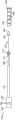
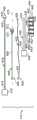
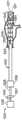
图1是本发明的用于植入动脉支架移植物的递送系统的一种实施方式的透视图。Figure 1 is a perspective view of one embodiment of the delivery system of the present invention for implanting an arterial stent graft.
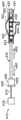
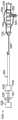
图2是本发明的图1的递送系统的透视图,示出用于从支架移植物假体周围缩回导引器护套的两个选项。2 is a perspective view of the delivery system of FIG. 1 of the present invention showing two options for retracting the introducer sheath from around the stent-graft prosthesis.
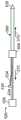
图3是支架移植物部署之前的图1所示的本发明的递送系统的横截面图。Figure 3 is a cross-sectional view of the delivery system of the present invention shown in Figure 1 prior to stent graft deployment.
图4是本发明的递送系统的转矩部件的远侧端部的一种实施方式的横截面图。4 is a cross-sectional view of one embodiment of the distal end of the torque member of the delivery system of the present invention.
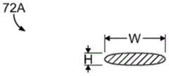
图5是图4所示的转矩部件的臂的横截面图示。5 is a cross-sectional illustration of an arm of the torque member shown in FIG. 4 .
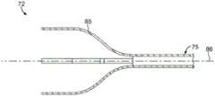
图6是本发明的递送系统的转矩部件的远侧端部的另一实施方式的横截面图。6 is a cross-sectional view of another embodiment of the distal end of the torque member of the delivery system of the present invention.
图7是本发明的转矩部件的替代臂的侧视图。Figure 7 is a side view of an alternative arm of the torque member of the present invention.
图8是本发明的递送系统的一种实施方式的侧视图,示出待递送的支架移植物和本发明的递送系统的转矩部件的一部分的相对定位。Figure 8 is a side view of one embodiment of the delivery system of the present invention showing the relative positioning of a stent-graft to be delivered and a portion of the torque component of the delivery system of the present invention.
图9是本发明的转矩部件的另一实施方式的透视图,其中转矩部件的臂限定开口。Figure 9 is a perspective view of another embodiment of the torque member of the present invention wherein the arms of the torque member define openings.
图10是限定开口的本发明的递送系统的臂的另一实施方式的透视图,其中缝线环从开口延伸。10 is a perspective view of another embodiment of an arm of a delivery system of the present invention defining an opening from which a loop of suture extends.
图11是图10所示的臂和缝线环的另一实施方式的侧视图,其中支架移植物的远侧端部通过缝线环固定到臂,缝线环延伸穿过由支架移植物的远侧端部限定的开口,以及延伸穿过本发明的缝线环的释放丝。11 is a side view of another embodiment of the arm and suture loop shown in FIG. 10, wherein the distal end of the stent-graft is secured to the arm by a suture loop extending through the arm of the stent-graft. An opening defined by the distal end, and a release wire extending through the suture loop of the present invention.
图12是本发明的递送系统的支架移植物和转矩部件的一部分替代布置的侧视图。12 is a side view of an alternate arrangement of a portion of the stent-graft and torque member of the delivery system of the present invention.
图13是支架移植物相对于本发明的递送系统的转矩部件的一部分的又一布置的侧视图。13 is a side view of yet another arrangement of a stent-graft relative to a portion of a torque component of a delivery system of the present invention.
图14是连接支架移植物和本发明的递送系统的转矩部件的一部分的又一实施方式的侧视图。14 is a side view of yet another embodiment of a portion of a torque member connecting a stent-graft to a delivery system of the present invention.
图15是连接支架移植物和递送系统的转矩部件的一部分的另一实施方式的侧视图。15 is a side view of another embodiment of a portion of a torque member connecting a stent-graft to a delivery system.
图16是支架移植物和支架移植物的内部支架相对于递送系统的转矩部件的布置的另一实施方式的侧视图。16 is a side view of another embodiment of a stent-graft and the arrangement of the inner stent of the stent-graft relative to the torque component of the delivery system.
图17是连接支架移植物(特别是支架移植物的外部支架)和递送系统的转矩部件的布置的另一实施方式的侧视图。17 is a side view of another embodiment of an arrangement connecting a stent-graft (particularly the outer stent of the stent-graft) and the torque member of the delivery system.
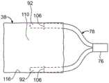
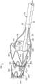
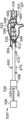
图18是图4所示的转矩部件与根据本发明的方法的实施方式部分部署的支架移植物的远侧端部相结合的三维图示。18 is a three-dimensional illustration of the torque member shown in FIG. 4 in combination with the distal end of a partially deployed stent-graft according to an embodiment of the method of the present invention.
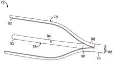
图19是图6所示的转矩部件与根据本发明的实施方式部分部署的支架移植物的远侧端部相结合的三维图示。19 is a three-dimensional illustration of the torque member shown in FIG. 6 in combination with the distal end of a partially deployed stent-graft in accordance with an embodiment of the present invention.
图20是本发明的递送系统的替代实施方式的横截面图示,递送系统还包括围绕支架移植物延伸并位于导引器护套内的柔性护套。Figure 20 is a cross-sectional illustration of an alternative embodiment of the delivery system of the present invention, the delivery system further comprising a flexible sheath extending around the stent graft and positioned within the introducer sheath.
图21是图3所示的本发明的递送系统的横截面图,其中导引器护套从支架移植物部分缩回。21 is a cross-sectional view of the delivery system of the present invention shown in FIG. 3 with the introducer sheath partially retracted from the stent graft.
图22是图21所示的递送系统的实施方式的横截面,其中导引器护套已经从支架移植物并也从本发明的递送系统的转矩部件的臂完全缩回。22 is a cross-section of the embodiment of the delivery system shown in FIG. 21 in which the introducer sheath has been fully retracted from the stent-graft and also from the arms of the torque member of the delivery system of the present invention.
图23是图22所示的本发明的递送系统的横截面图,其中支架移植物围绕导丝导管旋转,并且其中延伸穿过缝线的丝部分从缝线缩回以便部分释放支架移植物。23 is a cross-sectional view of the delivery system of the present invention shown in FIG. 22 with the stent-graft rotated about the guidewire catheter and with the wire portion extending through the suture retracted from the suture to partially release the stent-graft.
图24是图23所示的本发明的递送系统和支架移植物的横截面图,其中丝从缝线完全缩回,由此完全释放支架移植物。Figure 24 is a cross-sectional view of the delivery system and stent-graft of the present invention shown in Figure 23 with the wire fully retracted from the suture thereby fully releasing the stent-graft.
图25是图24所示的本发明的递送系统和支架移植物的横截面图,其中递送系统从完全部署的支架移植物部分缩回。Figure 25 is a cross-sectional view of the delivery system and stent-graft of the present invention shown in Figure 24, with the delivery system partially retracted from the fully deployed stent-graft.
图26是图25所示的本发明递送系统和支架移植物的横截面图,其中递送系统从完全部署的移植物部分缩回。Figure 26 is a cross-sectional view of the delivery system and stent-graft of the present invention shown in Figure 25, with the delivery system partially retracted from the fully deployed graft.
图27图26的递送系统的横截面图,其中递送系统从完全部署的支架移植物部分部署。Figure 27 is a cross-sectional view of the delivery system of Figure 26, wherein the delivery system is partially deployed from a fully deployed stent graft.
图28是图27的递送系统的横截面图,其中递送系统从完全部署的支架移植物部署。28 is a cross-sectional view of the delivery system of FIG. 27, wherein the delivery system is deployed from a fully deployed stent-graft.
图29是本发明的递送系统的另一实施方式的分解视图。Figure 29 is an exploded view of another embodiment of the delivery system of the present invention.
图30A是在通过递送系统的径向约束件约束的支架移植物部署之前处于组装状态的图29所示的递送系统的实施方式的侧视图。30A is a side view of the embodiment of the delivery system shown in FIG. 29 in an assembled state prior to deployment of a stent-graft constrained by radial constraints of the delivery system.
图30B是在径向约束件从支架移植物缩回之后的图29和30A的递送系统的侧视图。30B is a side view of the delivery system of FIGS. 29 and 30A after the radial constraint has been retracted from the stent-graft.
图30C是在转矩部件从支架移植物的远侧端部释放之后以及在递送系统从支架移植物移除由此植入支架移植物之后的图29、30A、30B的递送系统的侧视图。30C is a side view of the delivery system of FIGS. 29, 30A, 30B after the torque member is released from the distal end of the stent-graft and after the delivery system is removed from the stent-graft thereby implanting the stent-graft.
图31A是本发明的另一实施方式的透视图,其中图18所示的支架移植物递送系统的丝通过锚固环纵向锚固,锚固环位于由丝联接的圆形结扎线的端部近侧和远侧,由此径向收缩支架移植物,并且其中结扎线是圆形的,通过在圆形的径向相对点处与丝链接来收缩支架移植物。31A is a perspective view of another embodiment of the present invention wherein the wires of the stent-graft delivery system shown in FIG. 18 are longitudinally anchored by an anchoring ring positioned proximal to and from the end of a circular ligature joined by the wires. Distal, whereby the stent-graft is radially contracted, and wherein the ligature is circular, the stent-graft is contracted by linking with the wire at diametrically opposite points of the circle.
图31B是图31A所示的圆形结扎线的细节。Figure 31B is a detail of the circular ligature shown in Figure 31A.
图31C是图31A和31B的圆形结扎线在圆形结扎线的相对端部布置成通过丝链接由此围绕支架移植物固定圆形结扎线的细节。31C is a detail of the circular ligature of FIGS. 31A and 31B at opposite ends of the circular ligature disposed by a silk link thereby securing the circular ligature around the stent graft.
图32A是本发明的又一实施方式的透视图,其中图19的支架移植物递送系统的丝通过带缺口控制杆代替,其中结扎线横跨缺口,由此控制杆围绕其纵向轴线的旋转造成结扎线围绕控制杆卷绕,由此径向收缩支架移植物。32A is a perspective view of yet another embodiment of the present invention, wherein the wires of the stent-graft delivery system of FIG. 19 are replaced by a notched control rod, wherein the ligature straddles the notch, whereby rotation of the control rod about its longitudinal axis results in The ligature is wrapped around the lever, thereby radially contracting the stent-graft.
图32B是图32A所示的本发明的实施方式的透视图,但是其中支架移植物通过控制杆的旋转由此围绕控制杆卷绕结扎线来径向收缩。Figure 32B is a perspective view of the embodiment of the invention shown in Figure 32A, but wherein the stent-graft is radially contracted by rotation of the lever thereby wrapping the ligature around the lever.
图33是适用于本发明的控制杆的另一实施方式的细节的部件的分解视图。Figure 33 is an exploded view of the components of a detail of another embodiment of a control lever suitable for use in the present invention.
图34是组装时的图33所示的控制杆的部件部分的侧视图,示出延伸穿过内部管并横跨内部管开窗的丝,并且内部管位于外部管内,并且其中内部管和外部管的开窗对准。34 is a side view of the component parts of the lever shown in FIG. 33 when assembled, showing wires extending through the inner tube and fenestrated across the inner tube, and the inner tube is located within the outer tube, and wherein the inner tube and the outer tube are Align the fenestration of the tube.
图35A是图34和35所示的控制杆的细节的侧视图,其中横跨本发明的支架移植物递送系统的径向支架移植物的支架的支柱的结扎线在内部管开窗处穿过丝和内部管之间,并且同时内部管开窗与外部管开窗对准。35A is a side view of a detail of the control rod shown in FIGS. 34 and 35 with the ligatures spanning the struts of the stent of the radial stent-graft of the stent-graft delivery system of the present invention passed at the inner tube fenestration between the wire and the inner tube, and at the same time the inner tube fenestration is aligned with the outer tube fenestration.
图35B是图35A所示的实施方式的细节的侧视图,其中通过链接到控制杆的结扎线横跨的支架通过内部管相对于外部管向近侧缩回而径向收缩。35B is a side view of a detail of the embodiment shown in FIG. 35A in which a stent spanned by a ligature linked to a control rod is radially contracted by proximal retraction of the inner tube relative to the outer tube.
图35C是图35A所示的实施方式的侧视图,其中通过链接到控制杆的结扎线横跨的支架通过内部管围绕其纵向轴线旋转由此使结扎线围绕内部管卷绕而径向收缩。35C is a side view of the embodiment shown in FIG. 35A with the stent straddled by the ligature linked to the lever being radially contracted by the inner tube being rotated about its longitudinal axis thereby causing the ligature to wrap around the inner tube.
图36A是本发明的另一实施方式,如同图32A所示,但是其中控制杆是图33和34所示的控制杆。Fig. 36A is another embodiment of the invention, as shown in Fig. 32A, but in which the lever is that shown in Figs. 33 and 34 .
图36B是图36A所示的实施方式的透视图,但是其中围绕支架移植物的结扎线通过使内部管相对于外部管并相对于支架移植物向近侧运动由此将结扎线的一部分拉入外部管而径向收缩。36B is a perspective view of the embodiment shown in FIG. 36A , but wherein the ligature around the stent-graft is moved proximally with respect to the inner tube relative to the outer tube and relative to the stent-graft thereby pulling a portion of the ligature in. The outer tube shrinks radially.
图37是本发明的支架移植物递送系统的另一实施方式的分解视图,除了转矩部件之外,支架移植物递送系统包括围绕支架移植物的圆形结扎线约束件,其径向相对端部通过丝链接,并且其中支架移植物包括可以在支架移植物递送系统的鼻锥处可释放地固定到顶部捕获装置的近侧裸支架。37 is an exploded view of another embodiment of a stent-graft delivery system of the present invention comprising, in addition to a torque member, a circular ligature constraint surrounding the stent-graft with diametrically opposite ends thereof The parts are linked by silk, and wherein the stent graft comprises a proximal bare stent that can be releasably secured to the top capture device at the nose cone of the stent graft delivery system.
图38A是在支架移植物递送系统的导引器护套引导到跨越受体的动脉分支的动脉瘤之后的图37所示的支架移植物递送系统的组装侧视图。38A is an assembled side view of the stent-graft delivery system shown in FIG. 37 after the introducer sheath of the stent-graft delivery system has been guided to an aneurysm spanning an arterial branch of a recipient.
图38B是在导引器护套从支架移植物缩回由此暴露处于收缩位置的支架移植物之后的图38A所示的实施方式的侧视图。38B is a side view of the embodiment shown in FIG. 38A after the introducer sheath has been retracted from the stent-graft thereby exposing the stent-graft in a retracted position.
图38C是链接围绕支架移植物延伸的圆形结扎线的径向相对端部的丝缩回由此径向释放支架移植物之后的图38A和38B所示的实施方式的侧视图。38C is a side view of the embodiment shown in FIGS. 38A and 38B after the wires linking the diametrically opposite ends of the circular ligatures extending around the stent-graft have been retracted, thereby radially releasing the stent-graft.
图38D是转矩部件从支架移植物的远侧端部缩回之后的图38A-38C所示的实施方式的侧视图。38D is a side view of the embodiment shown in FIGS. 38A-38C after the torque member has been retracted from the distal end of the stent-graft.
图38E是裸支架从顶部捕获装置释放并且递送系统的没有植入动脉瘤部位的剩余部分从支架移植物缩回之后以及分支假体穿过开窗植入并进入由动脉瘤跨越的动脉分支之后的图38A-38D所示的实施方式的侧视图。Figure 38E is after the bare stent is released from the top capture device and the remainder of the delivery system without the implanted aneurysm site is retracted from the stent graft and after the branch prosthesis is implanted through the fenestration and into the artery branch spanned by the aneurysm Side views of the embodiment shown in Figures 38A-38D.
图39是本发明的支架移植物递送系统的另一实施方式的分解视图,支架移植物递送系统除了转矩部件之外包括可释放地附接到围绕支架移植物的结扎线的控制杆,控制杆可以控制结扎线横跨的支架移植物的支架的径向收缩。39 is an exploded view of another embodiment of a stent-graft delivery system of the present invention comprising, in addition to a torque component, a control rod releasably attached to a ligature around the stent-graft, the control The rod can control radial contraction of the stent of the stent-graft spanned by the ligature.
图40A是组装之后的图39所示的实施方式的侧视图,其中支架移植物被装载到支架移植物递送系统的导引器护套内。40A is a side view of the embodiment shown in FIG. 39 after assembly, with a stent-graft loaded into the introducer sheath of the stent-graft delivery system.
图40B是导引器护套缩回由此暴露支架移植物之后的图40A所示的实施方式的侧视图,同时它在通过围绕控制杆卷绕的结扎线跨越的支架移植物的支架处径向收缩。40B is a side view of the embodiment shown in FIG. 40A after the introducer sheath has been retracted thereby exposing the stent-graft while it is at the stent of the stent-graft spanned by a ligature wrapped around the lever. To shrink.
图40C是控制杆围绕其轴线旋转以允许由结扎线横跨的支架移植物径向扩张之后以及在结扎线从在近侧方向上缩回的控制杆释放之后的图40A和40B所示的实施方式的侧视图。40C is the implementation shown in FIGS. 40A and 40B after the lever is rotated about its axis to allow radial expansion of the stent graft spanned by the ligature and after the ligature is released from the lever retracted in the proximal direction. way side view.
图40D是转矩部件从支架移植物的远侧端部向近侧缩回之后的图40A-40C所示的实施方式的侧视图。40D is a side view of the embodiment shown in FIGS. 40A-40C after the torque member has been retracted proximally from the distal end of the stent-graft.
图40E是支架移植物的近侧端部处的裸支架在支架移植物递送系统的鼻锥处从顶部捕获装置释放之后以及没有植入动脉瘤部位的支架移植物递送系统释放以及分支假体穿过支架移植物的开窗植入到由动脉瘤跨越的动脉分支之后的图40A-40D所示的实施方式的侧视图。Figure 40E is the bare stent at the proximal end of the stent-graft after release from the top capture device at the nose cone of the stent-graft delivery system and the stent-graft delivery system without implantation at the aneurysm site and branch prosthesis penetration Side views of the embodiment shown in FIGS. 40A-40D after fenestrated implantation of a stent-graft into an artery branch spanned by an aneurysm.
图41是本发明的支架移植物递送系统的另一实施方式的横截面,其中支架移植物通过两级径向释放部件径向收缩,两级径向释放部件包括柔性护套和链接径向收缩缝线的端部的丝。Figure 41 is a cross-section of another embodiment of a stent-graft delivery system of the present invention wherein the stent-graft is radially contracted by a two-stage radial release component comprising a flexible sheath and links radially contracted The wire at the end of the suture.
图42是导引器护套向近侧缩回之后以及两级径向释放部件致动之前的图41所示的实施方式的横截面。42 is a cross-section of the embodiment shown in FIG. 41 after proximal retraction of the introducer sheath and prior to actuation of the two-stage radial release member.
具体实施方式Detailed ways
本发明总体针对用于植入假体的递送系统和用于治疗血管疾病的方法,诸如可以在开窗血管内动脉瘤修复中有益或需要的,其中医生需要在支架移植物通过例如在动脉管腔内部分扩张而局部部署之后旋转支架移植物。The present invention is generally directed to delivery systems for implantable prostheses and methods for treating vascular diseases, such as may be beneficial or desirable in fenestrated endovascular aneurysm repair, The stent-graft is rotated after local deployment by dilation of the luminal portion.
本发明的特征和其他细节(诸如本发明的步骤或本发明的部件组合)将更加特别地描述并在权利要求中指明。将理解到本发明的特定实施方式通过示例性示出,而不作为本发明的限制。本发明的主要特征可以在多种实施方式中采用,而不偏离本发明的范围。Features and other details of the invention, such as steps of the invention or combinations of parts of the invention, will be more particularly described and pointed out in the claims. It will be understood that the particular embodiments of the invention are shown by way of illustration and not as limitations of the invention. The principal characteristics of this invention can be employed in various embodiments without departing from the scope of the invention.
在本文中指代假体时,本文还指代待递送或植入患者中的“支架移植物”、“支架移植物”或“血管假体”,术语“近侧”指的是相对靠近患者心脏的假体部分或假体部件,并且“远侧”指的是相对远离患者心脏的假体部分或假体部件。When referring to a prosthesis herein, it also refers to a "stent-graft," "stent-graft," or "vascular prosthesis" to be delivered or implanted in a patient, the term "proximal" meaning relatively close to the patient's heart and "distal" refers to a prosthetic portion or prosthetic component that is relatively far from the patient's heart.
但是,在指代用来递送或植入假体的递送系统或递送系统部件时,所采用的术语“近侧”指的是更靠近使用递送系统的医生。在指代递送系统或递送系统部件时,本文所采用的术语“远侧”指的是进一步远离使用递送系统的医生。However, when referring to a delivery system or delivery system component used to deliver or implant a prosthesis, the term "proximal" as used means closer to the physician using the delivery system. As used herein, the term "distal" when referring to a delivery system or delivery system component means further away from the physician using the delivery system.
为了清楚起见,“接近”指的是“靠近”,与上面相对于假体或递送系统描述的“近侧”或“远侧”所描述的含义不同。For clarity, "proximal" means "near" as opposed to "proximal" or "distal" as described above with respect to the prosthesis or delivery system.
本发明的示例性实施方式在下面描述。Exemplary embodiments of the present invention are described below.
本发明的用于植入支架移植物假体的递送系统的一种实施方式在图1中示出。如本文所示,递送系统10包括具有位于近侧端部的近侧手柄14和位于远侧端部处的远侧手柄16的纵向主体12。导引器护套18(导引器护套是径向约束件的实施方式)从远侧手柄14向远侧延伸,并包括近侧端部20和远侧端部22。导丝导管24(图3)包括近侧端部26和远侧端部28(图2),并从纵向主体12的远侧端部16延伸。导丝导管24在导引器护套18内延伸穿过纵向主体12。导丝导管24的近侧端部26从纵向主体12的近侧手柄14延伸。One embodiment of the delivery system of the present invention for implanting a stent-graft prosthesis is shown in FIG. 1 . As shown herein,
鼻锥30固定到导丝导管24的远侧端部28(图2)。导丝导管24和鼻锥30限定导丝(未示出)可以延伸穿过其中的管腔通道。导引器护套18能够通过相对于纵向主体12的远侧手柄16缩回导引器护套18而沿着递送装置10的纵向轴线36在近侧方向11上相对于操作递送装置10的医生运动。在一种实施方式中,例如如图2所示,导引器护套18可以通过导螺杆螺母32的旋转来缩回,导螺杆螺母32与直接或间接固定导引器护套18的轨道34形成螺纹配合构型。图2的选项I示出螺杆螺母32的旋转,造成轨道34的纵向运动,并因此造成导引器护套18沿着递送装置10的纵向轴线36旋转。替代地,导螺杆螺母32可以沿着纵向主体12直接撤回,而不旋转,由此缩回导引器护套18,如选项II所示。可以看到,在任何选项中,导引器护套18的缩回至少暴露支架移植物38,同时导丝导管24和鼻锥30相对于纵向主体12保持固定。
在未示出的替代实施方式中,导引器护套18不链接到轨道34,而链接到纵向主体12的远侧手柄16,并且纵向主体12包括从导引器护套18的远侧端部22内向远侧引导导丝导管24和支架移植物38的近侧手柄部件,由此释放支架移植物38。如同图1和2示出的实施方式中,一旦支架移植物38释放,导丝导管24和鼻锥30以及导引器护套18都从受体缩回和撤回。In an alternative embodiment not shown, the
如图2所示,支架移植物38包括近侧端部40和远侧端部42。支架移植物38的管腔移植物部件44限定管腔46。支架48是自扩张,并且由支柱50形成,支柱50连接成形成近侧顶点52和远侧顶点54。在一种实施方式中,支架移植物38包括位于近侧端部40处的裸支架。裸支架56例如通过缝线、生物相容粘合剂或本领域普通技术人员已知的其他适当技术通过裸支架56的远侧顶点54在支架移植物38的近侧端部40处固定到管腔移植物部件44。管腔移植物部件44限定从近侧端部40延伸到远侧端部42的管腔。在某些实施方式中,管腔移植物部件44可包括分别位于近侧端部40和远侧端部42处的锯齿形部分55、57。管腔移植物部件44由适当材料形成,诸如本领域普通技术人员已知,例如包括膨胀的聚四氟乙烯(PTFE),诸如ePTFE和聚对苯二甲酸乙二醇酯(PET),诸如编织聚酯。支架48和裸支架56由适当材料形成,例如形状记忆合金(镍钛诺)或不锈钢。As shown in FIG. 2 ,
图3是支架移植物38从导引器护套18内部署之前的递送装置10的远侧部分的横截面图。在一种具体实施方式中,裸支架38处于第一被捕获状态,其中裸支架38的近侧顶点被固定到递送装置10的顶部捕获组件58。在一种实施方式中,顶部捕获组件58包括近侧捕获部件60和远侧捕获部件62。近侧捕获部件60包括从顶部捕获导管66向远侧延伸的尖头64,顶部捕获导管66围绕导丝导管24并在导丝导管24的近侧端部26处通过近侧夹持组件68固定到导丝导管24,如图2所示。在被捕获状态,如图3所示,尖头64延伸穿过在支架移植物38的管腔移植物部件44处由裸支架56限定的开口70(图2),由此防止裸支架56在支架移植物38的近侧端部40处径向扩张。顶部捕获导管66在近侧夹持组件68处从导丝导管24释放使得顶部捕获导管66和近侧捕获部件60从远侧捕获部件62向近侧运动,由此从尖头64释放裸支架56,由此使裸支架56从被捕获状态释放到释放状态。3 is a cross-sectional view of the distal portion of
转矩部件72包括推杆74、轮毂76和至少两个臂78。推杆74具有近侧端部(未示出)和远侧端部82,并围绕导丝导管24从近侧手柄14向远侧延伸。虽然未示出,推杆74的近侧端部固定到纵向主体12的近侧手柄14。近侧手柄14围绕纵向主体12旋转,由此造成推杆74围绕导丝导管24旋转。任选地,近侧手柄14可与导丝导管24和顶部捕获导管66锁定在一起,由此近侧手柄14的旋转造成导丝导管24和顶部捕获导管66轴向旋转。轮毂76限定管腔88,并固定到推杆74的远侧端部82。至少两个臂78从轮毂76向远侧延伸,并且围绕顶部捕获管腔66径向分布。
每个臂78能够通过使臂78从收缩状态释放而从图3所示的收缩状态扩张到图4所示的扩张状态。在一种实施方式中,臂78从收缩状态自扩张到扩张状态。臂78固定到转矩部件72的轮毂76,继而固定到转矩部件72的推杆74。Each
可以在图5中看到,臂78的宽度(W)大于臂78的高度(H)。在以垂直于轮毂的纵向轴线的角度上观看时,如图4所示,臂在扩张状态下具有曲线形状。在多种实施方式中,转矩部件72可以包括两个、三个或四个臂。臂78分别具有近侧端部90和远侧端部92。任选地,臂78的近侧端部90在轮毂76的周边围绕纵向轴线86均匀地间隔开。在一种实施方式中,每个臂78独立地具有大约1英寸和大约5英寸之间范围的长度。轮毂76和臂78由诸如镍钛诺或其他适当形状记忆合金、不锈钢、钛或塑料的适当材料形成。It can be seen in FIG. 5 that the width (W) of the
图6是图4的转矩部件的另一实施方式的横截面图,但是其中转矩部件没有轮毂部件。如本文所示,转矩部件72A包括连接到推杆75或推杆75的延伸部的臂85。替代地,转矩部件73包括作为铰接构件79的臂,如图7所示。在此实施方式中,构件79包括彼此结合并通过铰链83结合到轮毂88的分段81。构件79由诸如镍钛诺或其他适当形状记忆合金、不锈钢、钛或塑料的适当材料形成。6 is a cross-sectional view of another embodiment of the torque member of FIG. 4, but without a hub member. As shown herein, the
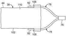
在部署之前,臂78的远侧端部92与支架移植物38接合,例如图8所示,并通过缝线106固定在支架移植物38的管腔46内。在另一实施方式中,如图9-11所示,至少一个臂78限定开口94,缝线环96延伸穿过开口94,并且缝线环96固定到开口。缝线环96还延伸穿过通过支架移植物38限定的开口98。释放丝100沿着递送装置10纵向延伸,其塞入鼻锥30或位于鼻锥30下方,如图3所示,并穿过缝线环96,如图11所示,由此将支架移植物38的远侧端部42固定到臂78。延伸穿过缝线环96的丝100的优点在导丝导管24和顶部捕获组件58(支架移植物38在被捕获状态下保持其上,通过缩回导引器护套18缩回而暴露,如图22所示)沿着纵向轴线36在动脉内运动以适当定位支架移植物38时获得。缝线96通过延伸穿过缝线96的丝100在支架移植物38的开口98处保持就位,并防止支架移植物的纵向塌缩,塌缩会在纵向定位时(包括导丝导管24和顶部捕获组件58的向近侧运动(朝着医生))通过支架移植物38和动脉壁之间的摩擦出现。Prior to deployment, distal ends 92 of
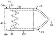
用于将支架移植物38的远侧端部42固定到臂78的替代布置在图12-17中示出。特别是,如图12所示,臂78可以沿着支架移植物38的外侧表面102延伸,并可以通过固定到支架移植物38的管腔移植物部件44的外部缝线104可释放地固定其上。如图13所示,支架移植物38的远侧端部42限定臂78从支架移植物的管腔46穿过其中向远侧延伸到支架移植物38的外侧表面102的狭槽108。替代地,如图14所示,臂78从支架移植物38的外侧表面102向远侧延伸穿过狭槽108到支架移植物38的管腔46。在又一实施方式中,如图15所示,臂78可以分别延伸穿过多个狭槽108、112,诸如从支架移植物38的外侧表面102向远侧穿过第一狭槽108到支架移植物的管腔46,并返回穿过第二狭槽112到支架移植物38的外侧部分102。An alternative arrangement for securing the
如图16和17所示,支架移植物38的支架部件可以用来将臂78固定到支架移植物38。例如,如图16所示,固定到管腔移植物部件44的内侧壁116的支架114可通过将臂78放置在支架114和管腔移植物部件44之间来帮助将臂78固定到支架移植物38。替代地,围绕支架移植物38的管腔移植物部件44的外侧表面102延伸的支架118可以通过将臂78放置在管腔移植物部件44和支架118之间来帮助固定臂78,如图17所示。As shown in FIGS. 16 and 17 , the stent component of
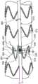
如图18所示,径向约束件120径向约束支架移植物38。在一种实施方式中,径向约束件120包括缝线122或线,其跨越支架移植物38的每个支架48。线100延伸穿过每个缝线122的环126,由此丝100从缝线122缩回使支架移植物38从径向约束件120释放。在一种替代实施方式中,如图19所示,转矩部件72A不包括轮毂。在此实施方式中,臂可以直接固定到推杆75或可以选择性地加工或切割杆的远侧端部以形成臂85和推杆75来制造。在又一实施方式中(未示出),丝100位于支架移植物的内部上并延伸穿过开口94、穿过缝线96到支架移植物内部。如图11所示,在一种实施方式中,丝100缩回也将从转矩部件72的臂78释放支架移植物38。替代地,径向约束件是在支架移植物38和导引器护套18之间延伸并塞入鼻锥30或位于鼻锥30下方的柔性护套128,如图20所示。As shown in FIG. 18 ,
在本发明的方法的一种实施方式中,图3所示的处于第一受约束状态的支架移植物38被引导到受体的动脉瘤部位。导引器护套18接着通过导螺杆螺母32围绕手柄主体12的轨道34旋转而缩回,如图2选项I所示,其中导螺杆螺母32邻靠远侧手柄16造成轨道34和与轨道34附接的导引器护套18相对于医生在近侧方向11上运动。替代地,或随后,导螺杆螺母32可通过医生在近侧方向11上拉动,以便导引器护套18相对于导丝导管24和支架移植物38在近侧方向11上缩回,如图2选项II所示。还可以从图19看到,导引器护套18在近侧方向11上至少部分缩回造成支架移植物38的近侧端部40从图3和18所示的第一受约束位置位移到通过径向约束件120保持的第二受约束位置。In one embodiment of the method of the present invention, the stent-
如图22所示,导引器护套18从支架移植物38和转矩部件72完全缩回造成支架移植物38沿着其整个长度采取第二受约束位置,其通过径向约束件120保持。同样,从第一受约束位置位移到第二受约束位置造成转矩部件72从图3、20和21所示的第一受约束位置径向扩张到图22所示的第二受约束位置。在导引器护套18至少部分缩回的同时将转矩力施加到转矩部件72造成支架移植物38围绕纵向轴线36旋转。As shown in FIG. 22 , full retraction of
例如,在支架移植物38位于图22所示的第二受约束位置时,转矩部件72可通过旋转近侧手柄14(图2)、旋转与其连接的推杆74(图23)而围绕导丝导管24旋转。转矩部件72的这种旋转使得支架移植物38的至少一个开窗39旋转对准,如图22-23所示。支架移植物38也可沿着纵向轴线36纵向运动(也称为轴向运动),以便将支架移植物38适当定位在动脉瘤部位。如上所述,延伸穿过臂78、管腔移植物部件44且丝100延伸穿过其中的缝线96将支架移植物38的远侧端部42固定到递送系统10,由此在顶部捕获组件58(其近侧端部40保持在图23所示的被捕获状态)的近侧运动(朝着医生)期间通过支架移植物38的远侧端部42和动脉壁之间的摩擦基本上防止支架移植物38的纵向塌缩。For example, when the stent-
在图24所示的实施方式中,径向约束件120的丝100从缝线122缩回,由此释放径向约束件120的缝线122,并允许支架38的剩余部分在径向上完全扩张并坐落在其适当位置,而不扭曲支架移植物38或损害手术部位,如图25所示。随后,转矩部件72从支架移植物38的远侧端部42缩回。接着通过在近侧夹持组件68处从导丝导管24释放顶部捕获导管66(图1和2),并且缩回近侧顶部捕获部件64和固定近侧顶部捕获部件64的顶部捕获导管66,由此使裸支架56从图26所示的其捕获状态释放到图27所示的释放状态,顶部捕获组件58得到致动。由于释放,支架移植物38的近侧端部40将在手术部位处坐落在其指定位置。如图28所示,导丝导管24和顶部捕获导管66可接着从支架移植物38缩回,并且递送装置10可从受体移除,由此完成程序。In the embodiment shown in FIG. 24, the
应该理解到可以采用其他递送装置来执行本发明的方法。例如,支架移植物38可以被引导到动脉瘤部位,而没有导引器护套18的帮助。在一种实施方式中,支架移植物38被引导到受体,同时只通过径向约束件120约束,而不通过导引器护套18约束。在另一实施方式中,该方法包括首先引导支架移植物38(在其处于第一受约束状态并位于导引器护套18内的同时)到动脉瘤部位远侧的位置,随后支架移植物从导引器护套18的远侧端部22推进到动脉瘤部位。It should be understood that other delivery devices may be employed to perform the methods of the present invention. For example, stent-
在另一实施方式中,径向约束件是导引器护套。例如,如图29的分解视图所示,本发明的用于植入支架移植物152的递送系统150(图29)包括近侧手柄154和远侧手柄156。导丝导管158包括近侧端部160和远侧端部162,并从远侧手柄154延伸。鼻锥164和顶部捕获装置157固定在导丝导管158的远侧端部162处。转矩部件166包括推杆168和至少两个臂172,至少两个臂172可以自扩张并从推杆延伸。任选地,包括作为推杆168和臂172之间的链接的轮毂170。轮毂170限定围绕纵向轴线176的管腔,并固定到推杆168。臂172围绕轮毂170径向布置,并从轮毂170向远侧延伸。径向约束件在此实施方式中是导引器护套174,其从远侧手柄156延伸。In another embodiment, the radial constraint is an introducer sheath. For example, as shown in the exploded view of FIG. 29 , a delivery system 150 ( FIG. 29 ) of the present invention for implanting a
图30A是图29所示的递送系统150的组装视图。可以在图30A-30C中看到,每个臂172能够从受约束状态运动到扩张状态。在一种实施方式中,转矩部件166的臂172呈现远离纵向轴线176的径向自扩张。导引器护套174在轮毂170和导丝导管158的远侧端部162之间纵向延伸,并径向约束从转矩部件166围绕导丝导管158向远侧延伸的支架移植物152。通过转矩部件166围绕纵向轴线176旋转将转矩力施加到臂172造成支架移植物152的开窗180围绕纵向轴线176旋转,直到在动脉瘤部位处旋转对准为止。在本发明的方法中,支架移植物152在径向约束件166内推进到动脉瘤部位,随后至少一个开窗180旋转对准。径向约束件166的旋转可以独立于导丝导管158或近侧手柄154的任何旋转。替代地,径向约束件166的旋转可以与导丝导管158的旋转相结合,诸如通过将转矩部件166锁定到近侧手柄154。径向约束件166从支架移植物152缩回造成自扩张臂172的径向扩张以及支架移植物152的自扩张,由此至少部分部署支架移植物152。如图30B所示,支架移植物152在裸支架159处通过诸如本领域已知的适当顶部捕获装置157而可释放地固定到导丝导管158的远侧端部162。裸支架159通过顶部捕获装置157的致动而从导丝导管158释放,并且递送系统150的未植入动脉瘤的剩余部分从支架移植物152和动脉瘤部位缩回,如图30C所示。FIG. 30A is an assembled view of the
在另一实施方式中,如图31A所示,作为图18所示的替代实施方式的支架移植物递送系统198包括围绕支架移植物38的周边延伸的圆形结扎线200,以形成通过丝46链接的圆形结扎线200的径向相对端部127、129。丝100通过锚固环202、204稳定。图31B是图31A所示的圆形结扎线200的细节,其在未围绕支架移植物28卷绕时构造成圆形。图31C是在被构造成围绕支架移植物28卷绕时的圆形结扎线200的细节。可以在图31A-31C中看到,圆形结扎线200的径向相对端部127、129在通过丝100链接时围绕支架移植物28固定圆形结扎线200。In another embodiment, as shown in FIG. 31A , a stent
本发明的支架移植物递送系统的另一实施方式在图32A中示出,其是图19所示的替代实施方式。如图32A所示,支架移植物递送系统290包括在支架移植物296处围绕支架294的周边延伸并通过缺口300可释放地固定到控制杆298的多个结扎线292,由此控制杆298的旋转造成支架移植物296的相应支架294一致收缩。在本发明的方法中,如图32A-32B所示,轴向旋转控制杆298造成结扎线292围绕控制杆298卷绕,由此径向收缩支架294,支架294在缺口300处由链接到控制杆298的结扎线292横跨。任选地,至少一个环291将控制杆298固定到支架移植物296的管腔移植物部件295。在另一实施方式中,至少一个环293将结扎线292固定到管腔移植物部件295。Another embodiment of the stent graft delivery system of the present invention is shown in FIG. 32A , which is an alternative embodiment to that shown in FIG. 19 . As shown in FIG. 32A , stent
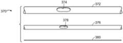
图33是本发明的支架移植物递送系统的控制杆的另一实施方式的分解视图。如图33所示,控制杆370包括限定外部管开窗374的外部管372。内部管376限定内部管开窗378。内部管376具有小于外部管372的内直径的直径。丝380具有小于内部管376的内直径的直径。在组装时,如图34所示,丝380纵向延伸穿过内部管376,并且内部管376在外部管372内纵向延伸。内部管开窗378与外部管开窗374对准,并且丝380横跨内部管开窗378和外部管开窗374。Figure 33 is an exploded view of another embodiment of the lever of the stent graft delivery system of the present invention. As shown in FIG. 33 , the
图35A是本发明的支架移植物递送系统的侧视图,其中图33和34的控制杆370在外侧表面384处沿着支架移植物382纵向延伸。结扎线386穿过丝380和内部管376的内侧表面之间,同时内部管开窗378和外部管开窗374对准。支架移植物382的包括支柱389的支架388可以通过在箭头373的方向上在外部管372内缩回内部管376来径向收缩,由此造成结扎线386在外部管372内拉动,如图35A-35B所示。在一种实施方式中,诸如其中结扎线386在控制杆370的任一侧上在支柱389上方径向延伸,结扎线386可以至少部分通过跨越结扎线386的至少一个结扎线缝线387稳定。在一种实施方式中,控制杆372通过控制杆缝线385在支架移植物382处稳定。35A is a side view of a stent graft delivery system of the present invention with
在本发明的方法的另一实施方式中,如图35A-35C所示,不是使内部管376和丝362在外部管372内缩回,结扎线386通过使内部管376相对于外部管372轴向旋转由此围绕内部管376卷绕结扎线386而径向收缩,径向收缩支架388,其支柱389被结扎线386横跨。In another embodiment of the method of the present invention, as shown in FIGS. 35A-35C , instead of retracting the
图36A是本发明的另一实施方式,如同图32A所示,但是其中控制杆270是图33和34所示那些。图36B是图36A所示的实施方式的透视图,但是其中围绕支架移植物296的结扎线292通过使内部管376相对于外部管372以及相对于支架移植物296向近侧运动由此将结扎线292的一部分拉入外部管372来径向收缩。FIG. 36A is another embodiment of the invention, as shown in FIG. 32A , but wherein the lever 270 is that shown in FIGS. 33 and 34 . 36B is a perspective view of the embodiment shown in FIG. 36A , but wherein the
图37是本发明的支架移植物递送系统的另一实施方式的分解侧视图。如本文所示,支架移植物递送系统410包括具有近侧端部414和远侧端部416的导丝导管412。近侧手柄418固定到导丝导管412的近侧端部414。鼻锥420和顶部捕获装置421固定到导丝导管412的远侧端部416。转矩部件466包括推杆468和从推杆468延伸的可以自扩张的至少两个臂472。任选地,包括作为推杆468和臂472之间的链接的轮毂470。轮毂470限定围绕纵向轴线476的管腔并固定到推杆468。臂472围绕轮毂470径向布置并从轮毂470向远侧延伸。转矩部件手柄467位于推杆468的近侧端部处。丝422包括近侧端部424和远侧端部426。丝422由诸如本领域已知的适当材料制造,包括例如镍钛诺或其他形状记忆合金。丝422是足够柔性的,而在推进到患者的动脉瘤期间不伤害患者。丝手柄428固定在丝422的近侧端部424处。导引器护套430包括近侧端部432和远侧端部434,并且远侧手柄436固定到导引器护套430的近侧端部432。支架移植物438包括近侧端部440、远侧端部442、管腔移植物部件444、沿着管腔移植物部件444分布的支架446以及如上所述布置并构造的结扎线448。裸支架449固定到支架移植物438的远侧端部。Figure 37 is an exploded side view of another embodiment of the stent graft delivery system of the present invention. As shown herein, a stent
图38A是图37所示的支架移植物递送系统410的组装侧视图,其中支架移植物438被装载到导引器护套430的远侧端部434内,并且如上所述至少部分通过穿过圆形结扎线448的径向相对端部150并穿过稳定锚固环453的丝422径向收缩。在一种实施方式中,支架移植物438包括开窗439。38A is an assembled side view of the stent-
在本发明的方法中,支架移植物递送系统410被推进到患者的动脉瘤452。在一种实施方式中,如图38A所示,导引器护套430被推进到动脉瘤452,由此将支架移植物438放置在动脉瘤452处。如图38B所示,远侧手柄436在箭头460所示的近侧方向上朝着近侧手柄418缩回,由此使导引器护套430从动脉瘤452处的支架移植物438缩回。可以在图38B中看到,不管导引器护套430缩回,支架移植物438通过延伸穿过结扎线448的结扎线环450的丝422保持在径向收缩位置,结扎线448横跨沿着支架移植物438纵向分布的支架446的支柱。但是理解到在替代实施方式中,其中丝422是足够刚性的,支架移植物递送系统410可以在动脉内推进到动脉瘤452远侧的位置,其中支架移植物438通过在箭头462所示的远侧方向上朝着远侧手柄436推进近侧手柄418和丝手柄428,由此将径向收缩的支架移植物418从导引器护套430引导到动脉瘤452。In the method of the present invention, stent
通过转矩部件466围绕纵向轴线476旋转将转矩力施加到臂472造成支架移植物452的开窗围绕纵向轴线476旋转,直到它在动脉瘤部位处旋转对准。在本发明的方法中,支架移植物452在径向约束件466内推进到动脉瘤452之后是至少一个开窗480的旋转对准。Application of a torque force to arm 472 by rotation of
在将支架移植物引导到横跨动脉瘤452的位置并且支架移植物在动脉瘤452处至少部分旋转和轴向对准之后,丝422从结扎线的环450和锚固环453缩回。丝手柄428在箭头460所示的方向上朝着近侧手柄418向近侧缩回使得丝422从结扎线448的缝线环450和锚固环453撤回,由此使得支架移植物438从图38B所示的其径向收缩状态完全扩张到图38C所示的径向扩张状态。如图38D所示,支架移植物452在裸支架459处通过诸如本领域已知的适当顶部捕获装置457可释放地固定到导丝导管458的远侧端部462。裸支架459通过致动顶部捕获装置457而从导丝导管458释放。随后,支架移植物438完全植入动脉瘤,并且支架移植物递送装置410的剩余部分从支架移植物438和患者缩回,如图10E所示,由此通过本发明的方法完成患者动脉瘤452的治疗。After the stent-graft is guided to a position across the
图39是本发明的支架移植物递送系统的另一实施方式的分解视图。如本文所示,支架移植物递送系统520包括具有近侧端部524和远侧端部526的导丝导管522。近侧手柄528固定到导丝导管522的近侧端部524。鼻锥530和顶部捕获装置531固定到导丝导管522的远侧端部526。控制杆532包括近侧端部534和远侧端部536。控制杆手柄538固定到控制杆532的近侧端部534。转矩部件566包括推杆568和可以从推杆568延伸并可以自扩张的至少两个臂572。任选地,包括作为推杆568和臂572之间的链接的轮毂570。轮毂570限定围绕纵向轴线576的管腔并固定到推杆568。臂572围绕轮毂570径向布置,并从轮毂570向远侧延伸。转矩部件手柄567位于推杆568的近侧端部处。控制杆532包括缺口533。支架移植物540包括管腔移植物部件542和支架544。支架544包括限定近侧顶点和远侧顶点的支柱546。结扎线548横跨支架544的支柱546。导引器护套550包括近侧端部552和远侧端部554。远侧手柄556固定到导引器护套550的近侧端部552。Figure 39 is an exploded view of another embodiment of the stent graft delivery system of the present invention. As shown herein, the stent
图40A是图39所示的递送系统的支架移植物的侧视图,但是在组装时,并且其中支架移植物540被装载到导引器护套550的远侧端部554内。在一种实施方式中,支架移植物540包括位于近侧开口端部552处的裸支架521,其具有近侧顶点和任选包括倒钩的远侧顶点。40A is a side view of the stent-graft of the delivery system shown in FIG. 39 , but assembled, and with the stent-
图40B是在将支架移植物递送系统520引导到患者的动脉瘤558(诸如主动脉瘤)处之后的图39和40A的支架移植物递送系统的侧视图,并且支架移植物递送系统520的支架移植物540的位置位于横跨动脉瘤部位558的位置。通过转矩部件566围绕纵向轴线576旋转将转矩力施加到臂572造成支架移植物552的开窗围绕纵向轴线576旋转,直到其在动脉瘤部位处旋转对准。在本发明的方法中,支架移植物562在径向约束件466内推进到动脉瘤452之后是至少一个开窗580的旋转对准。如图40B进一步所示,根据本发明的方法,支架移植物540位于动脉瘤558处,如图40A和40B所示,并且至少一个支架544通过在支架移植物540通过医生在箭头570所示的方向上定位在动脉瘤558处的同时围绕控制杆532卷绕的结扎线548而径向收缩。在图40B所示的实施方式中,支架移植物540通过医生在箭头570所示的方向上使远侧手柄556朝着近侧手柄528缩回而暴露于动脉瘤558。但是应该理解到,替代地,支架移植物540可通过在箭头572的方向上使近侧手柄528和控制杆532朝着远侧手柄556推进而从远侧端部559处的导引器护套550内推进到动脉瘤558。在任何情况下,横跨支柱544的结扎线548的部分的长度可以在支架移植物540定位在动脉瘤558处期间通过医生轴向旋转控制杆手柄538和随后旋转控制杆532来受控地增加或减小。在一种实施方式中,支架移植物540定位成使得支架移植物540处的开窗564与动脉分支560适当对准,以便随后将分支假体562穿过开窗564放置到动脉分支560。40B is a side view of the stent-graft delivery system of FIGS. 39 and 40A after introducing the stent-
在完成支架移植物定位在动脉瘤部位558时,结扎线548从控制杆532释放。根据控制杆532的实施方式,例如如上所述,结扎线548可如图40B-40C所示通过向近侧缩回控制杆532或通过其他方式(诸如通过在管内向近侧缩回丝,诸如参考图33-36B如上所述)从控制杆532释放,由此释放结扎线548。如图38D所示,支架移植物540可在裸支架521处通过诸如本领域已知的适当顶部捕获装置531可释放地固定到导丝导管522的远侧端部526。裸支架521通过致动顶部捕获装置531从导丝导管522释放,并且递送系统520的未植入动脉瘤558的剩余部分从支架移植物540和动脉瘤558缩回。接着完成支架移植物540的部署。Upon completion of stent graft positioning at
在本发明的支架移植物递送系统的另一实施方式中,如图41和42所示,该递送系统如同如上所述的图20和22所示的递送系统,但是除了护套128之外具有收缩缝线122和丝100。在此实施方式中,径向约束件120包括缝线122、丝100和柔性护套128。缝线122或线跨越支架移植物38的每个支架48。丝100延伸穿过每个缝线122的环126,由此丝100从缝线122缩回释放支架移植物38。柔性护套128在支架移植物28和导引器护套18之间延伸,并且塞入鼻锥30或在其下方。图42示出图41的支架移植物递送系统,但是在导引器护套18缩回之后,由此造成柔性护套128径向收缩支架移植物120。支架移植物120的两级扩张因此是可能的,由此柔性护套128从支架移植物120向近侧收缩以及支架移植物120的随后部分径向扩张是第一阶段,并且丝100从缝线122径向缩回随后允许支架移植物120完全径向扩张(但是用于释放裸支架56)构成第二阶段。In another embodiment of the stent graft delivery system of the present invention, shown in FIGS. 41 and 42, the delivery system is like the delivery system shown in FIGS.
虽然未示出,应该理解到控制杆可以用于本发明的装置和方法,以独立径向收缩支架移植物的多个纵向部分,诸如支架移植物的近侧部分和远侧部分。还理解到多个控制杆可以均匀地、与支架移植物内的开窗相结合而均匀地、或以另一型式或不均匀地围绕支架移植物径向分布。还理解到本发明的支架移植物递送系统可包括分别单独和独立控制支架的相同部分(特别是支架的近侧部分)的径向扩张的多个控制杆。多个控制杆围绕管腔移植物部件(未示出)的外侧表面或内侧表面的周边相对于彼此横向和纵向布置。Although not shown, it is understood that control rods may be used in the devices and methods of the present invention to independently radially contract multiple longitudinal portions of a stent-graft, such as proximal and distal portions of the stent-graft. It is also understood that the plurality of control rods may be distributed radially around the stent-graft uniformly, uniformly in conjunction with fenestrations within the stent-graft, or in another pattern or non-uniformly. It is also understood that the stent graft delivery system of the present invention may comprise a plurality of control rods each individually and independently controlling the radial expansion of the same portion of the stent, particularly the proximal portion of the stent. A plurality of control rods are arranged laterally and longitudinally relative to each other around the perimeter of either the lateral or medial surface of the luminal graft component (not shown).
本文引用的所有专利、公开的申请和参考文献的教导通过引用整体并入。本文引用的所有专利、公开的申请和参考文献的相关教导通过引用整体并入。美国专利No.8,292,943、7,763,063、8,308,790、8,070,790、8,740,963、8,007,605、9,320,631、8,062,349、9,198,786、8,062,345、9,561,124、9,173,755、8,449,595、8,636,788、9,333,104、9,408,734、9,408,735、8,500,792、9,220,617、9,364,314、9,101,506、8,998,970、9,554,929、9,439,751、9,592,112、9,655,712、9,827,123、9,877,857、9,907,686、美国专利申请No.14/575,673、15/166,818、15/167,055、14/272,818、14/861,479、15/478,424、15/478,737、15/587,664、15/604,032、15/672,404、15/816,772、15/839,272、15/417,467、PCT/US2017/025844、PCT/US2017/025849、PCT/US2017/025912、PCT/US2017/034223、PCT/US2017/046062、PCT/US2018/019355、PCT/US2018/019344、PCT/US2018/019349、PCT/US2018/019353、PCT/US2018/019354、PCT/US2018/019352、PCT/US2018/019342、PCT/US2018/019350、PCT/US2018/019356以及PCT/US2018/019351的相关教导也通过引用整体并入。The teachings of all patents, published applications, and references cited herein are incorporated by reference in their entirety. The relevant teachings of all patents, published applications, and references cited herein are incorporated by reference in their entirety. U.S. Patent Nos. 8,292,943, 7,763,063, 8,308,790, 8,070,790, 8,740,963, 8,007,605, 9,320,631, 8,062,349, 9,198,786, 8,062,345, 9,561,124, 9,173,75 5, 8,449,595, 8,636,788, 9,333,104, 9,408,734, 9,408,735, 8,500,792, 9,220,617, 9,364,314, 9,101,506, 8,998,970, 9,554,929, 9,439,751, 9,592,112, 9,655,712, 9,827,123, 9,877,857, 9,907,686, US Patent Application Nos. 14/575,673, 15/166,818, 15/167,055, 14/272,818, 14/861,479, 5/478,424, 15/478,737, 15/587,664, 15 /604,032, 15/672,404, 15/816,772, 15/839,272, 15/417,467, PCT/US2017/025844, PCT/US2017/025849, PCT/US2017/025912, PCT/US2017/034223, PCT/US2 017/046062, PCT /US2018/019355, PCT/US2018/019344, PCT/US2018/019349, PCT/US2018/019353, PCT/US2018/019354, PCT/US2018/019352, PCT/US2018/019342, PCT/US2018/019 350. PCT/US2018 /019356 and the related teachings of PCT/US2018/019351 are also incorporated by reference in their entirety.
虽然已经特别示出和描述了示例性实施方式,本领域普通技术人员将理解到可以进行形式和细节的多种变化而不偏离由所附权利要求所涵盖的实施方式的范围。例如,尽管未示出,本发明的方法或作为递送系统的部件中所采用的支架移植物的至少一个开窗可包括PCT/US2018/019352所描述的开窗锁定件;PCT/US2018/019353所描述的可动开窗;PCT/US2018/019351所描述的开窗环;以及PCT/US2018/019350所描述的折叠适配器,这些相关教导也通过引用整体并入。同样例如,尽管未示出,本发明的递送系统中所使用的柔性护套可包括将造成柔性护套具有管腔构型的开口布置,管腔构型具有收缩直径和延伸穿过开口以造成开口与该布置相符的结扎线,由此使柔性护套构造成与管腔构型的收缩径向直径相符,结扎线能够从开口向近侧缩回,由此从收缩径向直径释放柔性护套,如PCT/US2018/019354所述,这些相关教导也通过引用整体并入。While exemplary embodiments have been particularly shown and described, it will be understood by those of ordinary skill in the art that various changes in form and details may be made without departing from the scope of the embodiments encompassed by the appended claims. For example, although not shown, at least one fenestration of a stent-graft employed in the methods of the present invention or as part of a delivery system may include a fenestration lock as described in PCT/US2018/019352; PCT/US2018/019353 the movable fenestration described in PCT/US2018/019351; and the folding adapter described in PCT/US2018/019350, the relevant teachings of which are also incorporated by reference in their entirety. Also for example, although not shown, the flexible sheath used in the delivery system of the present invention may include an arrangement of openings that will cause the flexible sheath to have a lumen configuration having a constricted diameter and extending through the opening to create A ligature whose opening conforms to this arrangement whereby the flexible sheath is configured to conform to the contracted radial diameter of the lumen configuration, the ligature can be retracted proximally from the opening thereby releasing the flexible sheath from the contracted radial diameter set, as described in PCT/US2018/019354, the related teachings of which are also incorporated by reference in their entirety.
Claims (28)
Translated fromChineseApplications Claiming Priority (3)
| Application Number | Priority Date | Filing Date | Title |
|---|---|---|---|
| US201762579482P | 2017-10-31 | 2017-10-31 | |
| US62/579,482 | 2017-10-31 | ||
| PCT/US2018/019510WO2019089071A1 (en) | 2017-10-31 | 2018-02-23 | Distal torque component, delivery system and method of using same |
Publications (2)
| Publication Number | Publication Date |
|---|---|
| CN110121319A CN110121319A (en) | 2019-08-13 |
| CN110121319Btrue CN110121319B (en) | 2023-05-09 |
Family
ID=61683892
Family Applications (1)
| Application Number | Title | Priority Date | Filing Date |
|---|---|---|---|
| CN201880005338.2AActiveCN110121319B (en) | 2017-10-31 | 2018-02-23 | Distal torque component, delivery system, and method of use thereof |
Country Status (6)
| Country | Link |
|---|---|
| US (2) | US11376145B2 (en) |
| EP (3) | EP3558175B1 (en) |
| JP (2) | JP7168566B2 (en) |
| CN (1) | CN110121319B (en) |
| ES (2) | ES2910187T3 (en) |
| WO (1) | WO2019089071A1 (en) |
Families Citing this family (21)
| Publication number | Priority date | Publication date | Assignee | Title |
|---|---|---|---|---|
| US9782282B2 (en) | 2011-11-14 | 2017-10-10 | W. L. Gore & Associates, Inc. | External steerable fiber for use in endoluminal deployment of expandable devices |
| US9877858B2 (en) | 2011-11-14 | 2018-01-30 | W. L. Gore & Associates, Inc. | External steerable fiber for use in endoluminal deployment of expandable devices |
| US9375308B2 (en) | 2012-03-13 | 2016-06-28 | W. L. Gore & Associates, Inc. | External steerable fiber for use in endoluminal deployment of expandable devices |
| EP3903732B1 (en) | 2016-06-13 | 2025-07-30 | Bolton Medical, Inc. | Devices for reinforcing fenestrations in prosthetic implants |
| AU2017306141A1 (en) | 2016-08-02 | 2019-03-07 | Aortica Corporation | Systems, devices, and methods for coupling a prosthetic implant to a fenestrated body |
| EP3932373B1 (en) | 2017-02-24 | 2022-12-21 | Bolton Medical, Inc. | Delivery system for radially constricting a stent graft |
| ES2863978T3 (en) | 2017-02-24 | 2021-10-13 | Bolton Medical Inc | System for radially constricting a stent graft |
| WO2018156850A1 (en) | 2017-02-24 | 2018-08-30 | Bolton Medical, Inc. | Stent graft with fenestration lock |
| CA3055567C (en)* | 2017-03-08 | 2021-11-23 | W. L. Gore & Associates, Inc. | Steering wire attach for angulation |
| JP7271510B2 (en) | 2017-09-25 | 2023-05-11 | ボルトン メディカル インコーポレイテッド | Systems, devices and methods for coupling prosthetic implants to fenestrated bodies |
| AU2018439076B2 (en) | 2018-08-31 | 2022-07-07 | W. L. Gore & Associates, Inc. | Apparatus, system, and method for steering an implantable medical device |
| US11065139B2 (en)* | 2019-01-08 | 2021-07-20 | Covidien Lp | Apparatuses for stent delivery and positioning to cover an access site |
| EP3917461B1 (en) | 2019-02-01 | 2025-07-16 | Bolton Medical, Inc. | Expandable luminal stents |
| CN111035486B (en)* | 2019-12-25 | 2024-01-23 | 上海微创心脉医疗科技(集团)股份有限公司 | Stent delivery system and method of loading stents |
| KR20220149561A (en)* | 2020-02-28 | 2022-11-08 | 이베이스크 뉴로베스쿨러 리미티드 파트너쉽 | Endovascular prosthesis delivery system |
| CN113940786B (en)* | 2020-06-30 | 2024-10-22 | 上海微创心脉医疗科技(集团)股份有限公司 | Bracket system |
| US20220346994A1 (en)* | 2021-03-04 | 2022-11-03 | Aquedeon Medical, Inc. | Vascular and aortic connectors with robotic delivery and deployment methods thereof |
| CN113017952B (en)* | 2021-05-26 | 2021-10-08 | 上海微创心脉医疗科技(集团)股份有限公司 | Branch sheath and delivery system |
| WO2022265985A1 (en) | 2021-06-14 | 2022-12-22 | Bolton Medical, Inc. | Support ring, aortic prosthesis and method of forming |
| WO2022265989A1 (en) | 2021-06-14 | 2022-12-22 | Bolton Medical, Inc. | Support ring vascular aortic repair and methods of use |
| CN117100473B (en)* | 2023-09-27 | 2024-03-01 | 南微纽诺医学科技(南京)有限公司 | Conveying system for cavity operation |
Family Cites Families (150)
| Publication number | Priority date | Publication date | Assignee | Title |
|---|---|---|---|---|
| US5123917A (en) | 1990-04-27 | 1992-06-23 | Lee Peter Y | Expandable intraluminal vascular graft |
| US5242452A (en) | 1991-10-11 | 1993-09-07 | Kanji Inoue | Device for collapsing an appliance collapsible for insertion into human organs |
| FR2688401B1 (en) | 1992-03-12 | 1998-02-27 | Thierry Richard | EXPANDABLE STENT FOR HUMAN OR ANIMAL TUBULAR MEMBER, AND IMPLEMENTATION TOOL. |
| US5507769A (en) | 1994-10-18 | 1996-04-16 | Stentco, Inc. | Method and apparatus for forming an endoluminal bifurcated graft |
| US6113623A (en) | 1994-04-20 | 2000-09-05 | Cabinet Beau De Lomenie | Prosthetic device and method for eventration repair |
| US6015429A (en) | 1994-09-08 | 2000-01-18 | Gore Enterprise Holdings, Inc. | Procedures for introducing stents and stent-grafts |
| US5713948A (en) | 1995-07-19 | 1998-02-03 | Uflacker; Renan | Adjustable and retrievable graft and graft delivery system for stent-graft system |
| US6878161B2 (en) | 1996-01-05 | 2005-04-12 | Medtronic Vascular, Inc. | Stent graft loading and deployment device and method |
| ATE290832T1 (en) | 1996-01-05 | 2005-04-15 | Medtronic Inc | EXPANDABLE ENDOLUMINAL PROSTHESES |
| EP1595513A3 (en) | 1996-06-20 | 2010-09-15 | Vascutek Limited | Prosthetic repair of body passages |
| AUPO700897A0 (en) | 1997-05-26 | 1997-06-19 | William A Cook Australia Pty Ltd | A method and means of deploying a graft |
| AUPP083597A0 (en) | 1997-12-10 | 1998-01-08 | William A Cook Australia Pty Ltd | Endoluminal aortic stents |
| AU2078599A (en) | 1998-01-08 | 1999-07-26 | Mark Wilson Ian Webster | Self-expanding bifurcation stent and delivery system |
| US5910144A (en) | 1998-01-09 | 1999-06-08 | Endovascular Technologies, Inc. | Prosthesis gripping system and method |
| US6395018B1 (en) | 1998-02-09 | 2002-05-28 | Wilfrido R. Castaneda | Endovascular graft and process for bridging a defect in a main vessel near one of more branch vessels |
| US6776791B1 (en)* | 1998-04-01 | 2004-08-17 | Endovascular Technologies, Inc. | Stent and method and device for packing of same |
| US6171334B1 (en) | 1998-06-17 | 2001-01-09 | Advanced Cardiovascular Systems, Inc. | Expandable stent and method of use |
| GB2365356A (en) | 1999-05-07 | 2002-02-20 | Salviac Ltd | An embolic protection device |
| US6610087B1 (en) | 1999-11-16 | 2003-08-26 | Scimed Life Systems, Inc. | Endoluminal stent having a matched stiffness region and/or a stiffness gradient and methods for providing stent kink resistance |
| AU3826601A (en) | 2000-02-15 | 2001-08-27 | Eva Corp | Temporary stent assembly for use in a surgical procedure |
| US6761733B2 (en) | 2001-04-11 | 2004-07-13 | Trivascular, Inc. | Delivery system and method for bifurcated endovascular graft |
| US6733521B2 (en) | 2001-04-11 | 2004-05-11 | Trivascular, Inc. | Delivery system and method for endovascular graft |
| US6821291B2 (en) | 2001-06-01 | 2004-11-23 | Ams Research Corporation | Retrievable stent and method of use thereof |
| US20020193872A1 (en) | 2001-06-18 | 2002-12-19 | Trout Hugh H. | Prosthetic graft assembly and method of use |
| US20040117003A1 (en) | 2002-05-28 | 2004-06-17 | The Cleveland Clinic Foundation | Minimally invasive treatment system for aortic aneurysms |
| AU2003258337A1 (en) | 2002-08-23 | 2004-03-11 | Cook Incorporated | Asymmetric stent graft attachment |
| US20040059406A1 (en) | 2002-09-20 | 2004-03-25 | Cully Edward H. | Medical device amenable to fenestration |
| US9125733B2 (en) | 2003-01-14 | 2015-09-08 | The Cleveland Clinic Foundation | Branched vessel endoluminal device |
| JP4566988B2 (en) | 2003-04-02 | 2010-10-20 | ボストン サイエンティフィック リミテッド | Separable and recoverable stent assembly |
| US20040267348A1 (en)* | 2003-04-11 | 2004-12-30 | Gunderson Richard C. | Medical device delivery systems |
| US8500792B2 (en) | 2003-09-03 | 2013-08-06 | Bolton Medical, Inc. | Dual capture device for stent graft delivery system and method for capturing a stent graft |
| US20080264102A1 (en)* | 2004-02-23 | 2008-10-30 | Bolton Medical, Inc. | Sheath Capture Device for Stent Graft Delivery System and Method for Operating Same |
| US9198786B2 (en) | 2003-09-03 | 2015-12-01 | Bolton Medical, Inc. | Lumen repair device with capture structure |
| US7763063B2 (en) | 2003-09-03 | 2010-07-27 | Bolton Medical, Inc. | Self-aligning stent graft delivery system, kit, and method |
| US8292943B2 (en) | 2003-09-03 | 2012-10-23 | Bolton Medical, Inc. | Stent graft with longitudinal support member |
| DE602004018169D1 (en) | 2003-10-10 | 2009-01-15 | Cook William Europ | STENT WINDOW |
| US8808351B2 (en) | 2003-10-10 | 2014-08-19 | Cook Medical Technologies Llc | Stretchable prosthesis fenestration |
| US7425219B2 (en) | 2003-10-10 | 2008-09-16 | Arshad Quadri | System and method for endoluminal grafting of bifurcated and branched vessels |
| WO2005034807A1 (en) | 2003-10-10 | 2005-04-21 | William A. Cook Australia Pty. Ltd | Composite stent graft |
| ATE392865T1 (en) | 2003-10-10 | 2008-05-15 | Cook William A Australia | STENT IMPLANTS WITH WINDOWS |
| US20050096725A1 (en) | 2003-10-29 | 2005-05-05 | Pomeranz Mark L. | Expandable stent having removable slat members |
| EP1738793A4 (en) | 2004-04-16 | 2011-09-07 | Kawasumi Lab Inc | STENT DEVICE AND FIXED CHIP |
| US8308789B2 (en) | 2004-07-16 | 2012-11-13 | W. L. Gore & Associates, Inc. | Deployment system for intraluminal devices |
| US7758626B2 (en)* | 2004-07-20 | 2010-07-20 | Medtronic Vascular, Inc. | Device and method for delivering an endovascular stent-graft having a longitudinally unsupported portion |
| DE602005024585D1 (en)* | 2004-09-28 | 2010-12-16 | Cook William Europ | DEVICE FOR TREATING AORTIAL DISEASE |
| US7306623B2 (en) | 2005-01-13 | 2007-12-11 | Medtronic Vascular, Inc. | Branch vessel graft design and deployment method |
| US7918880B2 (en) | 2005-02-16 | 2011-04-05 | Boston Scientific Scimed, Inc. | Self-expanding stent and delivery system |
| EP1922029B1 (en)* | 2005-08-18 | 2014-11-19 | Cook Medical Technologies LLC | Assembly of stent grafts |
| US8911491B2 (en) | 2005-09-02 | 2014-12-16 | Medtronic Vascular, Inc. | Methods and apparatus for treatment of aneurysms adjacent branch arteries including branch artery flow lumen alignment |
| US8435284B2 (en) | 2005-12-14 | 2013-05-07 | Boston Scientific Scimed, Inc. | Telescoping bifurcated stent |
| US9155641B2 (en) | 2006-03-09 | 2015-10-13 | Cook Medical Technologies Llc | Expandable stent grafts |
| US9757260B2 (en)* | 2006-03-30 | 2017-09-12 | Medtronic Vascular, Inc. | Prosthesis with guide lumen |
| FR2899096B1 (en)* | 2006-04-04 | 2008-12-05 | Perouse Soc Par Actions Simpli | DEVICE FOR TREATING A CIRCULATION CIRCULATION OF THE BLOOD AND METHOD OF PREPARING SAID DEVICE |
| US20070244547A1 (en) | 2006-04-18 | 2007-10-18 | Medtronic Vascular, Inc., A Delaware Corporation | Device and Method for Controlling the Positioning of a Stent Graft Fenestration |
| US7678141B2 (en) | 2006-04-18 | 2010-03-16 | Medtronic Vascular, Inc. | Stent graft having a flexible, articulable, and axially compressible branch graft |
| AU2007258592B2 (en) | 2006-06-06 | 2012-10-25 | Cook Incorporated | Stent with a crush-resistant zone |
| US20080132988A1 (en) | 2006-12-01 | 2008-06-05 | Scimed Life Systems, Inc. | Balloon geometry for delivery and deployment of shape memory polymer stent with flares |
| US9358142B2 (en) | 2007-04-24 | 2016-06-07 | W. L. Gore & Associates, Inc. | Catheter having guidewire channel |
| AU2008251804B2 (en) | 2007-05-11 | 2013-01-10 | Cook Incorporated | Stent grafts for the thoracic aorta |
| US7637940B2 (en) | 2007-07-06 | 2009-12-29 | Boston Scientific Scimed, Inc. | Stent with bioabsorbable membrane |
| EP2231214A2 (en) | 2007-12-21 | 2010-09-29 | Boston Scientific Scimed, Inc. | Flexible stent-graft device having patterned polymeric coverings |
| US8974518B2 (en) | 2008-03-25 | 2015-03-10 | Medtronic Vascular, Inc. | Eversible branch stent-graft and deployment method |
| US8236040B2 (en) | 2008-04-11 | 2012-08-07 | Endologix, Inc. | Bifurcated graft deployment systems and methods |
| AU2009236062A1 (en) | 2008-04-18 | 2009-10-22 | Cook Medical Technologies Llc | Branched vessel prosthesis |
| US20090264990A1 (en) | 2008-04-21 | 2009-10-22 | Medtronic Vascular, Inc. | Radiopaque Imprinted Ink Marker for Stent Graft |
| CA2727000C (en) | 2008-06-04 | 2014-01-07 | Gore Enterprise Holdings, Inc. | Controlled deployable medical device and method of making the same |
| FR2932979B1 (en) | 2008-06-25 | 2012-04-06 | Perouse Lab | INTRODUCING DEVICE EXTENDING BETWEEN A PROXIMAL POINT AND A DISTAL POINT AND NECESSARY FOR TREATMENT THEREOF. |
| CN102076281B (en) | 2008-06-30 | 2014-11-05 | 波顿医疗公司 | Systems and methods for abdominal aortic aneurysm |
| EP2520320B1 (en) | 2008-07-01 | 2016-11-02 | Endologix, Inc. | Catheter system |
| JP5531016B2 (en) | 2008-08-27 | 2014-06-25 | ザ クリーヴランド クリニック ファウンデーション | Stent graft fixation coupling |
| US8353943B2 (en) | 2008-08-29 | 2013-01-15 | Cook Medical Technologies Llc | Variable weave graft with metal strand reinforcement for in situ fenestration |
| EP2349124B1 (en)* | 2008-09-05 | 2018-10-17 | Cook Medical Technologies LLC | Apparatus for improved stent deployment |
| WO2010030370A1 (en) | 2008-09-12 | 2010-03-18 | William A. Cook Australia Pty. Ltd. | Radiopaque reinforcing member |
| GB2464978B (en) | 2008-10-31 | 2010-10-20 | Cook William Europ | Introducer for deploying a stent graft in a curved lumen |
| EP3284447B1 (en) | 2009-03-13 | 2020-05-20 | Bolton Medical Inc. | System for deploying an endoluminal prosthesis at a surgical site |
| US8506622B2 (en) | 2009-04-17 | 2013-08-13 | Medtronic Vascular, Inc. | Mobile external coupling for branch vessel connection |
| US20110054587A1 (en) | 2009-04-28 | 2011-03-03 | Endologix, Inc. | Apparatus and method of placement of a graft or graft system |
| AU2009202301B8 (en) | 2009-06-10 | 2009-12-03 | Cook Incorporated | Reinforcing ring |
| JP2013500792A (en) | 2009-07-30 | 2013-01-10 | ストライカー コーポレイション | Stent delivery system |
| US20110077730A1 (en) | 2009-09-30 | 2011-03-31 | Fenster Michael S | Bifurcated balloon stent |
| US8926693B2 (en) | 2010-02-17 | 2015-01-06 | Medtronic, Inc. | Heart valve delivery catheter with safety button |
| US8764811B2 (en) | 2010-04-20 | 2014-07-01 | Medtronic Vascular, Inc. | Controlled tip release stent graft delivery system and method |
| US8333800B2 (en) | 2010-04-29 | 2012-12-18 | Medtronic Vascular, Inc. | Mobile external coupling with internal sealing cuff for branch vessel connection |
| AU2010210022B1 (en) | 2010-08-05 | 2011-09-08 | Cook Incorporated | Stent graft having a marker and a reinforcing and marker ring |
| US9101455B2 (en) | 2010-08-13 | 2015-08-11 | Cook Medical Technologies Llc | Preloaded wire for endoluminal device |
| US8870939B2 (en) | 2010-08-21 | 2014-10-28 | Cook Medical Technologies Llc | Prosthesis having pivoting fenestration |
| US8702786B2 (en) | 2010-08-21 | 2014-04-22 | Cook Medical Technologies Llc | Prosthesis having pivoting fenestration |
| WO2012047308A1 (en) | 2010-10-08 | 2012-04-12 | Nitinol Devices And Components, Inc. | Alternating circumferential bridge stent design and methods for use thereof |
| US9095466B2 (en) | 2010-11-16 | 2015-08-04 | W. L. Gore & Associates, Inc. | Apposition fiber for use in endoluminal deployment of expandable devices in tortuous anatomies |
| US9198787B2 (en)* | 2010-12-31 | 2015-12-01 | Cook Medical Technologies Llc | Conformable prosthesis delivery system and method for deployment thereof |
| SG191921A1 (en) | 2011-01-14 | 2013-08-30 | Idev Technologies Inc | Stent delivery system with pusher assembly |
| US8641752B1 (en) | 2011-01-20 | 2014-02-04 | W. L. Gore & Associates, Inc. | Integrated sheath and deployment |
| US9155619B2 (en) | 2011-02-25 | 2015-10-13 | Edwards Lifesciences Corporation | Prosthetic heart valve delivery apparatus |
| US9839542B2 (en) | 2011-04-19 | 2017-12-12 | Medtronic Ardian Luxembourg S.A.R.L. | Mobile external coupling for branch vessel connection |
| EP3583916B1 (en) | 2011-04-28 | 2023-12-06 | Cook Medical Technologies LLC | Apparatus for facilitating deployment of an endoluminal prosthesis |
| US8840659B2 (en) | 2011-04-28 | 2014-09-23 | Cook Medical Technologies Llc | Stent and stent-graft designs |
| KR101945066B1 (en)* | 2011-04-29 | 2019-02-08 | 이베이스크 뉴로베스쿨러 엔터프라이즈 유엘씨 | Endovascular prosthesis and delivery device |
| US8728148B2 (en) | 2011-11-09 | 2014-05-20 | Cook Medical Technologies Llc | Diameter reducing tie arrangement for endoluminal prosthesis |
| US9387097B2 (en) | 2011-11-16 | 2016-07-12 | W. L. Gore & Associates, Inc. | Implant assembly with tactile indicator |
| CN106420107B (en) | 2011-11-16 | 2019-02-05 | 波顿医疗公司 | The device and method of reparation for aortic branch blood vessel |
| EP2985007B1 (en) | 2011-12-22 | 2019-11-13 | Cook Medical Technologies LLC | Preloaded wire for endoluminal device |
| US11623438B2 (en) | 2012-01-16 | 2023-04-11 | Merit Medical Systems, Inc. | Rotational spun material covered medical appliances and methods of manufacture |
| DE102012101103B3 (en) | 2012-02-10 | 2013-07-04 | Jotec Gmbh | Stentgraft with fixation elements and insertion system |
| US9375308B2 (en) | 2012-03-13 | 2016-06-28 | W. L. Gore & Associates, Inc. | External steerable fiber for use in endoluminal deployment of expandable devices |
| EP2846743B1 (en) | 2012-04-12 | 2016-12-14 | Bolton Medical Inc. | Vascular prosthetic delivery device |
| US9095421B2 (en) | 2012-04-18 | 2015-08-04 | Medtronic Vascular, Inc. | Multi-leaflet coupling for branch vessel connection |
| US8968384B2 (en) | 2012-04-27 | 2015-03-03 | Medtronic Vascular, Inc. | Circumferentially constraining sutures for a stent-graft |
| WO2014020609A1 (en) | 2012-08-01 | 2014-02-06 | Endospan Ltd. | Stent-grafts configured for post-implantation expansion |
| CA2881535A1 (en) | 2012-08-10 | 2014-02-13 | Altura Medical, Inc. | Stent delivery systems and associated methods |
| AU2012258395B1 (en) | 2012-11-27 | 2013-03-28 | Cook Medical Technologies Llc | Assembly of stent grafts with diameter reducing ties |
| AU2012258394B1 (en) | 2012-11-27 | 2013-03-07 | Cook Medical Technologies Llc | Stent graft having a closeable fenestration |
| EP2745813A1 (en) | 2012-12-18 | 2014-06-25 | Cook Medical Technologies LLC | Preloaded wire for endoluminal device |
| US9498361B2 (en) | 2012-12-19 | 2016-11-22 | Cook Medical Technologies Llc | Repositionable diameter constraints |
| US10350096B2 (en) | 2012-12-26 | 2019-07-16 | Cook Medical Technologies Llc | Expandable stent-graft system having diameter reducing connectors |
| CN103908356A (en) | 2012-12-28 | 2014-07-09 | 库克医学技术有限责任公司 | Prosthesis having pivoting fenestration |
| CN104717942A (en) | 2013-01-08 | 2015-06-17 | 泰尔茂株式会社 | Stent delivery device |
| US9655754B2 (en) | 2013-01-10 | 2017-05-23 | Trivascular, Inc. | Systems and methods for guidewire crossover for bifurcated prostheses |
| CN104027187B (en) | 2013-03-04 | 2016-05-25 | 微创心脉医疗科技(上海)有限公司 | Branched membrane-covered support, the induction system that comprises it and manufacture method thereof |
| EP3146993B1 (en) | 2013-03-15 | 2018-06-06 | Bolton Medical, Inc. | Hemostasis valve and delivery systems |
| US9439751B2 (en) | 2013-03-15 | 2016-09-13 | Bolton Medical, Inc. | Hemostasis valve and delivery systems |
| WO2014162306A2 (en) | 2013-04-02 | 2014-10-09 | Tendyne Holdings, Inc. | Improved devices and methods for transcatheter prosthetic heart valves |
| EP3666227A1 (en) | 2013-06-14 | 2020-06-17 | Avantec Vascular Corporation | Inferior vena cava filter and retrieval systems |
| DE102013106463A1 (en) | 2013-06-20 | 2014-12-24 | Jotec Gmbh | stent graft |
| CN105517508B (en) | 2013-07-22 | 2018-05-22 | 阿特利姆医疗公司 | Implants having expandable regions and methods of making and using same |
| WO2015057838A1 (en)* | 2013-10-15 | 2015-04-23 | Boston Scientific Scimed, Inc. | Methods and systems for loading and delivering a stent |
| DE102013111593A1 (en) | 2013-10-21 | 2015-04-23 | Jotec Gmbh | Vascular implant with areas of different radial force |
| CN104622600B (en)* | 2013-11-15 | 2017-12-19 | 微创心脉医疗科技(上海)有限公司 | A kind of art medium-height trestle system |
| WO2015075708A1 (en) | 2013-11-19 | 2015-05-28 | Endospan Ltd. | Stent system with radial-expansion locking |
| AU2014200124B1 (en) | 2014-01-08 | 2014-10-02 | Cook Medical Technologies Llc | A stent graft and delivery device having a low profile |
| CN203815663U (en) | 2014-04-14 | 2014-09-10 | 林晨 | Caliber-adjustable jacket-type aorta aortamembrana tectoria support |
| US9877854B2 (en) | 2014-05-21 | 2018-01-30 | Boston Scientific Scimed, Inc. | Stent delivery system |
| US9974671B2 (en) | 2014-11-03 | 2018-05-22 | Medtronic Vascular, Inc. | Devices and methods for treating aneurysms and other vascular conditions |
| CN106029005B (en) | 2014-12-18 | 2018-01-19 | 恩都思潘有限公司 | The Endovascular stent-graft of horizontal conduit with tired resistance |
| US10092428B2 (en) | 2014-12-30 | 2018-10-09 | Cook Medical Technologies Llc | Low profile prosthesis delivery device |
| US20160184078A1 (en) | 2014-12-31 | 2016-06-30 | Cordis Corporation | Sectional Inserts for Trunk Section in Endoprosthesis for Aortic Aneurysm |
| AU2016207060B2 (en) | 2015-01-14 | 2018-10-18 | Cook Medical Technologies Llc | Suture and wire stent deployment system |
| EP3250157B1 (en)* | 2015-01-28 | 2024-08-28 | Aortic Innovations, LLC | Modular endo-aortic device |
| EP3078349B1 (en) | 2015-04-10 | 2019-06-19 | Cook Medical Technologies LLC | Prosthesis with fenestration |
| FR3042702B1 (en) | 2015-10-26 | 2021-12-24 | Id Nest Medical | ELASTIC CROWN AND ASSOCIATED TREATMENT DEVICE FOR IMPLEMENTATION IN A BODY FLUID CIRCULATION DUCT |
| CN105943213B (en) | 2015-12-23 | 2019-01-04 | 微创心脉医疗科技(上海)有限公司 | Stent delivery system and its application method |
| CN109069282A (en) | 2016-04-05 | 2018-12-21 | 波顿医疗公司 | Delivery system and application method with guide and distal sheath |
| CN105832447A (en) | 2016-05-27 | 2016-08-10 | 杨威 | Covered stent for aortic dissection surgery, delivery device and use method thereof |
| EP3903732B1 (en) | 2016-06-13 | 2025-07-30 | Bolton Medical, Inc. | Devices for reinforcing fenestrations in prosthetic implants |
| US10433991B2 (en) | 2016-07-18 | 2019-10-08 | Cook Medical Technologies Llc | Controlled expansion stent graft delivery system |
| AU2017306141A1 (en) | 2016-08-02 | 2019-03-07 | Aortica Corporation | Systems, devices, and methods for coupling a prosthetic implant to a fenestrated body |
| WO2018156854A1 (en) | 2017-02-24 | 2018-08-30 | Bolton Medical, Inc. | Radially adjustable stent graft delivery system |
| EP3381416B1 (en) | 2017-03-29 | 2020-07-22 | Cook Medical Technologies LLC | Prosthesis with flexible stent |
| JP7271510B2 (en) | 2017-09-25 | 2023-05-11 | ボルトン メディカル インコーポレイテッド | Systems, devices and methods for coupling prosthetic implants to fenestrated bodies |
| EP3917461B1 (en) | 2019-02-01 | 2025-07-16 | Bolton Medical, Inc. | Expandable luminal stents |
| US10987873B2 (en) | 2019-03-15 | 2021-04-27 | Formlabs, Inc. | Techniques for mixing in additive fabrication and related systems and methods |
- 2018
- 2018-02-23CNCN201880005338.2Apatent/CN110121319B/enactiveActive
- 2018-02-23EPEP18711730.4Apatent/EP3558175B1/enactiveActive
- 2018-02-23EPEP22150465.7Apatent/EP4049633B1/enactiveActive
- 2018-02-23ESES18711730Tpatent/ES2910187T3/enactiveActive
- 2018-02-23WOPCT/US2018/019510patent/WO2019089071A1/ennot_activeCeased
- 2018-02-23JPJP2019533355Apatent/JP7168566B2/enactiveActive
- 2018-02-23ESES22150465Tpatent/ES3033002T3/enactiveActive
- 2018-02-23EPEP25154457.3Apatent/EP4578424A3/enactivePending
- 2019
- 2019-06-06USUS16/433,823patent/US11376145B2/enactiveActive
- 2022
- 2022-06-21USUS17/845,530patent/US20220313464A1/enactivePending
- 2022-10-27JPJP2022172320Apatent/JP7498246B2/enactiveActive
Also Published As
| Publication number | Publication date |
|---|---|
| US20190321207A1 (en) | 2019-10-24 |
| JP2021505212A (en) | 2021-02-18 |
| EP4578424A3 (en) | 2025-07-09 |
| JP2022191508A (en) | 2022-12-27 |
| EP3558175A1 (en) | 2019-10-30 |
| ES2910187T3 (en) | 2022-05-11 |
| CN110121319A (en) | 2019-08-13 |
| EP4578424A2 (en) | 2025-07-02 |
| US11376145B2 (en) | 2022-07-05 |
| EP3558175B1 (en) | 2022-01-12 |
| JP7168566B2 (en) | 2022-11-09 |
| WO2019089071A1 (en) | 2019-05-09 |
| JP7498246B2 (en) | 2024-06-11 |
| EP4049633A1 (en) | 2022-08-31 |
| US20220313464A1 (en) | 2022-10-06 |
| EP4049633B1 (en) | 2025-03-26 |
| ES3033002T3 (en) | 2025-07-29 |
Similar Documents
| Publication | Publication Date | Title |
|---|---|---|
| CN110121319B (en) | Distal torque component, delivery system, and method of use thereof | |
| CN110114037B (en) | Radially adjustable stent graft delivery system | |
| JP7516587B2 (en) | Tetherable stent graft and delivery system | |
| US12083030B2 (en) | Stent graft delivery system with constricted sheath and method of use | |
| CN109843226B (en) | Delivery systems and methods of use for radially contracting stent grafts | |
| EP3585306B1 (en) | System to radially constrict a stent graft | |
| JP4743836B2 (en) | Chest introducer | |
| EP2204141B1 (en) | Prosthesis deployment system retention device | |
| EP2387379B1 (en) | Stent graft and introducer assembly | |
| US20080021538A1 (en) | Controlled Deployment Delivery System | |
| GB2536439A (en) | Medical device assembly with constriction mechanism |
Legal Events
| Date | Code | Title | Description |
|---|---|---|---|
| PB01 | Publication | ||
| PB01 | Publication | ||
| SE01 | Entry into force of request for substantive examination | ||
| SE01 | Entry into force of request for substantive examination | ||
| GR01 | Patent grant | ||
| GR01 | Patent grant |