CN110109239B - Light sheet illumination microscopic imaging method and system for simultaneous multilayer imaging - Google Patents
Light sheet illumination microscopic imaging method and system for simultaneous multilayer imagingDownload PDFInfo
- Publication number
- CN110109239B CN110109239BCN201910364615.5ACN201910364615ACN110109239BCN 110109239 BCN110109239 BCN 110109239BCN 201910364615 ACN201910364615 ACN 201910364615ACN 110109239 BCN110109239 BCN 110109239B
- Authority
- CN
- China
- Prior art keywords
- imaging
- sample
- layer
- medium
- objective lens
- Prior art date
- Legal status (The legal status is an assumption and is not a legal conclusion. Google has not performed a legal analysis and makes no representation as to the accuracy of the status listed.)
- Active
Links
Images


Classifications
- G—PHYSICS
- G02—OPTICS
- G02B—OPTICAL ELEMENTS, SYSTEMS OR APPARATUS
- G02B21/00—Microscopes
- G02B21/06—Means for illuminating specimens
- G—PHYSICS
- G02—OPTICS
- G02B—OPTICAL ELEMENTS, SYSTEMS OR APPARATUS
- G02B21/00—Microscopes
- G02B21/16—Microscopes adapted for ultraviolet illumination ; Fluorescence microscopes
- G—PHYSICS
- G06—COMPUTING OR CALCULATING; COUNTING
- G06T—IMAGE DATA PROCESSING OR GENERATION, IN GENERAL
- G06T17/00—Three dimensional [3D] modelling, e.g. data description of 3D objects
- G—PHYSICS
- G06—COMPUTING OR CALCULATING; COUNTING
- G06T—IMAGE DATA PROCESSING OR GENERATION, IN GENERAL
- G06T2200/00—Indexing scheme for image data processing or generation, in general
- G06T2200/08—Indexing scheme for image data processing or generation, in general involving all processing steps from image acquisition to 3D model generation
Landscapes
- Physics & Mathematics (AREA)
- General Physics & Mathematics (AREA)
- Chemical & Material Sciences (AREA)
- Analytical Chemistry (AREA)
- Optics & Photonics (AREA)
- Engineering & Computer Science (AREA)
- Computer Graphics (AREA)
- Geometry (AREA)
- Software Systems (AREA)
- Theoretical Computer Science (AREA)
- Microscoopes, Condenser (AREA)
- Investigating, Analyzing Materials By Fluorescence Or Luminescence (AREA)
Abstract
Translated fromChinese
Description
Translated fromChinese技术领域technical field
本发明涉及显微成像技术领域,更具体地,涉及一种同时多层成像的光片照明显微成像方法及系统。The invention relates to the technical field of microscopic imaging, and more particularly, to a light sheet illumination microscopic imaging method and system for simultaneous multi-layer imaging.
背景技术Background technique
光片照明显微镜利用一束侧向照明的片状光束激活样本的预设深度,具有微米量级的层析能力。垂直至于光片方向,采用宽场成像方式,为快速获取样本三维空间信息提供了帮助。由于光片照明显微镜每次只会激活待成像层,因此相比于传统的点扫描成像方式,具有更小的光漂白和光毒性,适合长时间的活体生物样本成像。Light-sheet illumination microscopy utilizes a side-illuminated sheet-like beam to activate a preset depth of the sample, with micron-scale tomographic capabilities. As for the direction of the light sheet, the wide-field imaging method is adopted, which provides help for the rapid acquisition of the three-dimensional spatial information of the sample. Since the light sheet illumination microscope only activates the layer to be imaged each time, it has less photobleaching and phototoxicity than the traditional point scanning imaging method, and is suitable for long-term imaging of living biological samples.
但是传统的光片照明显微镜每次只产生单个光片,利用机械扫描的方式,同步轴向扫描照明光片和成像物镜以实现3D成像。这样的成像方式,一方面引入机械式扫描会限制成像速度,另一方面每次只成像样本的单个平面,通过后期轴向堆叠实现三维成像,极大的限制了三维成像的速度。However, the traditional light sheet illumination microscope only produces a single light sheet at a time, and uses mechanical scanning to synchronize the axial scanning of the illumination light sheet and the imaging objective to achieve 3D imaging. In this imaging method, on the one hand, the introduction of mechanical scanning will limit the imaging speed, and on the other hand, only a single plane of the sample is imaged at a time, and three-dimensional imaging is realized by axial stacking in the later stage, which greatly limits the speed of three-dimensional imaging.
发明内容SUMMARY OF THE INVENTION
针对现有技术的缺陷,本发明的目的在于解决传统光片照明显微镜三维成像速度慢的技术问题。In view of the defects of the prior art, the purpose of the present invention is to solve the technical problem that the three-dimensional imaging speed of the traditional light sheet illumination microscope is slow.
为实现上述目的,第一方面,本发明提供一种同时多层成像的光片照明显微成像方法,包括以下步骤:In order to achieve the above object, in a first aspect, the present invention provides a light sheet illumination microscopy imaging method for simultaneous multi-layer imaging, comprising the following steps:
产生照射到样本不同深度的多层片状照明光束,以激发样本不同深度的荧光;Generate multi-layer sheet-like illumination beams irradiated to different depths of the sample to excite fluorescence at different depths of the sample;
通过在成像物镜和样本之间引入折射率不匹配的介质,以拉长所述成像物镜在沿样本深度方向的成像点扩散函数,使得所述成像物镜可以收集样本不同深度的荧光信号;所述介质和成像物镜均位于样本上方,所述介质位于成像物镜和样本之间,所述介质的折射率和介质与成像物镜之间空气的折射率不匹配;By introducing a refractive index mismatched medium between the imaging objective lens and the sample, the imaging point spread function of the imaging objective lens along the depth direction of the sample is elongated, so that the imaging objective lens can collect fluorescence signals at different depths of the sample; the Both the medium and the imaging objective are located above the sample, the medium is located between the imaging objective and the sample, and the refractive index of the medium does not match the refractive index of the air between the medium and the imaging objective;
基于拉长后的成像点扩散函数、多层片状照明光束的不同深度信息以及收集到的样本不同深度的荧光信号进行三维重建,得到样本的三维结构。The three-dimensional structure of the sample is obtained by performing three-dimensional reconstruction based on the elongated imaging point spread function, the different depth information of the multi-layer sheet-like illumination beam, and the collected fluorescence signals at different depths of the sample.
可选地,通过改变照射到样本的多层片状平行照明光束的深度,实现对样本不同深度的三维成像。Optionally, three-dimensional imaging of different depths of the sample is achieved by changing the depth of the multi-layer sheet-like parallel illumination beams irradiated to the sample.
可选地,所述介质的折射率相比介质和成像物镜之间空气的折射率高,所述介质为水、油或者玻璃。Optionally, the refractive index of the medium is higher than the refractive index of air between the medium and the imaging objective lens, and the medium is water, oil or glass.
可选地,利用三维的图像反卷积算法和对应的不同深度成像点扩散函数对样本不同深度的荧光信号进行重建,得到样本的三维结构。Optionally, a three-dimensional image deconvolution algorithm and corresponding imaging point spread functions of different depths are used to reconstruct the fluorescence signals at different depths of the sample to obtain the three-dimensional structure of the sample.
第二方面,本发明提供一种同时多层成像的光片照明显微成像系统,包括:多层光束产生装置、多层信号成像装置、成像结果处理装置;In a second aspect, the present invention provides a light sheet illumination microscopy imaging system for simultaneous multi-layer imaging, comprising: a multi-layer beam generating device, a multi-layer signal imaging device, and an imaging result processing device;
所述多层光束产生装置,用于产生照射到样本不同深度的多层片状照明光束,以激发样本不同深度的荧光;The multi-layer light beam generating device is used to generate multi-layer sheet-like illumination light beams irradiated to different depths of the sample, so as to excite the fluorescence of different depths of the sample;
所述多层信号成像装置,包括成像物镜和介质,所述介质和成像物镜均位于样本上方,所述介质位于成像物镜和样本之间,所述介质的折射率和介质与成像物镜之间空气的折射率不匹配,所述多层信号成像装置通过在成像物镜和样本之间引入折射率不匹配的介质,以拉长所述成像物镜在沿样本深度方向的成像点扩散函数,使得所述成像物镜可以收集样本不同深度的荧光信号;The multilayer signal imaging device includes an imaging objective lens and a medium, the medium and the imaging objective lens are both located above the sample, the medium is located between the imaging objective lens and the sample, the refractive index of the medium and the air between the medium and the imaging objective lens The refractive index mismatch of the multi-layer signal imaging device extends the imaging point spread function of the imaging objective lens along the depth direction of the sample by introducing a medium with refractive index mismatch between the imaging objective lens and the sample, so that the Imaging objectives can collect fluorescence signals at different depths of the sample;
所述成像结果处理装置,用于基于拉长后的成像点扩散函数、多层片状照明光束的不同深度信息以及收集到的样本不同深度的荧光信号进行三维重建,得到样本的三维结构。The imaging result processing device is used for performing three-dimensional reconstruction based on the elongated imaging point spread function, different depth information of the multi-layer sheet-shaped illumination beam, and the collected fluorescence signals at different depths of the sample to obtain the three-dimensional structure of the sample.
可选地,所述多层光束产生装置包括:照明模块和光束整形模块;Optionally, the multi-layer light beam generating device includes: a lighting module and a beam shaping module;
所述照明模块,用于产生均匀的光斑;The lighting module is used to generate a uniform light spot;
所述光束整形模块,用于基于所述均匀的光斑产生照射到样本不同深度的多层片状平行照明光束。The beam shaping module is used for generating multi-layer sheet-like parallel illumination beams irradiating different depths of the sample based on the uniform light spot.
可选地,所述介质的折射率相比介质和成像物镜之间空气的折射率高,所述介质为水、油或者玻璃。Optionally, the refractive index of the medium is higher than the refractive index of air between the medium and the imaging objective lens, and the medium is water, oil or glass.
可选地,所述光束整形模块改变其照射到样本的多层片状平行照明光束的深度,实现对样本不同深度的三维成像。Optionally, the beam shaping module changes the depth of the multi-layer sheet-like parallel illumination beams irradiated to the sample, so as to realize three-dimensional imaging of different depths of the sample.
可选地,所述照明模块包括:激光器、激光扩束单元以及激光反射镜;Optionally, the lighting module includes: a laser, a laser beam expanding unit and a laser mirror;
所述激光器,用于提供激发样本荧光所需的光源;the laser is used to provide the light source required to excite the fluorescence of the sample;
所述激光扩束单元,用于对所述光源进行扩束,得到均匀光斑;The laser beam expanding unit is used to expand the beam of the light source to obtain a uniform light spot;
所述激光反射镜,用于将扩束后的均匀光斑反射到光束整形模块。The laser mirror is used for reflecting the expanded uniform light spot to the beam shaping module.
可选地,所述成像结果处理装置用于利用三维的图像反卷积算法和对应的不同深度成像点扩散函数对样本不同深度的荧光信号进行重建,得到样本的三维结构。Optionally, the imaging result processing device is configured to use a three-dimensional image deconvolution algorithm and corresponding imaging point spread functions of different depths to reconstruct the fluorescence signals at different depths of the sample to obtain the three-dimensional structure of the sample.
总体而言,通过本发明所构思的以上技术方案与现有技术相比,具有以下有益效果:In general, compared with the prior art, the above technical solutions conceived by the present invention have the following beneficial effects:
本发明提供的同时多层成像的光片照明显微成像方法及系统,相对于传统的光片照明显微镜,本发明在成像物镜与样本之间引入了折射率不匹配的介质,由于成像物镜和折射率不匹配介质的共同作用,从而在Z轴拉长了成像物镜的成像点扩散函数,为同时多层成像提供基础。然而只有Z轴拉长的成像点扩散函数,仍然无法实现真正的同时多层成像。本发明通过产生可以同时照射到样本不同深度的片状照明光来同时激活样本不同深度荧光,该不同深度荧光信号的xy面投影进一步被荧光相机收集。利用3D的反卷积图像等图像重构算法,从不同深度xy面投影图像中计算得到样本真实的三维分布。The light sheet illumination microscopy imaging method and system for simultaneous multi-layer imaging provided by the present invention, compared with the traditional light sheet illumination microscope, the present invention introduces a refractive index mismatched medium between the imaging objective lens and the sample, because the imaging objective lens and The combined action of the refractive index mismatch media elongates the imaging point spread function of the imaging objective in the Z-axis, providing the basis for simultaneous multilayer imaging. However, only with the elongated imaging point spread function of the Z axis, it is still impossible to achieve true simultaneous multi-layer imaging. The present invention simultaneously activates the fluorescence at different depths of the sample by generating sheet-shaped illumination light that can simultaneously irradiate the sample at different depths, and the xy plane projections of the fluorescence signals at different depths are further collected by a fluorescence camera. Using image reconstruction algorithms such as 3D deconvolution images, the real three-dimensional distribution of the samples is calculated from the xy plane projection images of different depths.
本发明提供的同时多层成像的光片照明显微成像系统,通过同时多层照明和成像样本不同深度的信号,避免了传统光片照明显微镜系统中的成像物镜和照明光片的机械扫描,并利用后期的3D图像重构算法,使得光片照明显微镜三维成像的时间分辨率有了数量级尺度的提升。The light sheet illumination microscope imaging system for simultaneous multi-layer imaging provided by the present invention avoids the mechanical scanning of the imaging objective lens and the illumination light sheet in the traditional light sheet illumination microscope system through simultaneous multi-layer illumination and imaging of signals of different depths of the sample. And using the later 3D image reconstruction algorithm, the temporal resolution of the 3D imaging of the light sheet illumination microscope has been improved by orders of magnitude.
附图说明Description of drawings
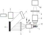
图1为本发明提供的同时多层成像的光片照明显微成像系统示意图;1 is a schematic diagram of a light sheet illumination microscopy imaging system for simultaneous multi-layer imaging provided by the present invention;
图2(a)为传统的光片照明显微镜的3D成像原理示意图;Figure 2(a) is a schematic diagram of the 3D imaging principle of a traditional light sheet illumination microscope;
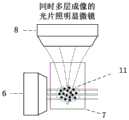
图2(b)为本发明提供的同时多层成像的光片照明显微镜的3D成像原理示意图;Figure 2(b) is a schematic diagram of the 3D imaging principle of the light sheet illumination microscope for simultaneous multi-layer imaging provided by the present invention;
图3为本发明提供的光束整形模块产生的不同深度的多层片状平行照明光束空间结构示意图;3 is a schematic diagram of the spatial structure of multi-layer sheet-like parallel illumination beams of different depths generated by the beam shaping module provided by the present invention;
图4(a)为传统的光片照明显微镜的未被拉长的成像点扩散函数示意图;Figure 4(a) is a schematic diagram of the unstretched imaging point spread function of a conventional light sheet illumination microscope;
图4(b)为本发明提供的同时多层成像的光片照明显微镜的被拉长的成像点扩散函数示意图;Figure 4(b) is a schematic diagram of the elongated imaging point spread function of the light sheet illumination microscope for simultaneous multi-layer imaging provided by the present invention;
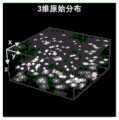
图5(a)为本发明提供的在拉长成像点扩散函数情况下,在样本深度方向上逐层照亮样本不同深度,得到的10um荧光小球3维原始分布;Figure 5(a) shows the 3-dimensional original distribution of 10um fluorescent spheres obtained by illuminating different depths of the sample layer by layer in the depth direction of the sample under the condition of elongating the imaging point spread function provided by the present invention;
图5(b)为本发明提供的在拉长成像点扩散函数情况下,利用光束整形模块同时照亮10个不同的样本深度的示意图;Figure 5(b) is a schematic diagram of simultaneously illuminating 10 different sample depths by using a beam shaping module under the condition of elongated imaging point spread function provided by the present invention;
图5(c)为本发明提供的在拉长成像点扩散函数情况下,利用光束整形模块同时照亮10个不同样本深度时在xy面上投影的图像;Figure 5(c) is an image projected on the xy plane when the beam shaping module is used to illuminate 10 different sample depths at the same time under the condition of elongating the imaging point spread function provided by the present invention;
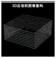
图5(d)为本发明提供的利用3D反卷积重构算法得到的恢复图像质量的10um荧光小球原始3D结构;Figure 5(d) is the original 3D structure of the 10um fluorescent sphere with restored image quality obtained by utilizing the 3D deconvolution reconstruction algorithm provided by the present invention;
图6为本发明提供的同时多层成像的光片照明显微成像方法流程图;6 is a flow chart of a light sheet illumination microscopy imaging method for simultaneous multi-layer imaging provided by the present invention;
在所有附图中,相同的附图标记用来表示相同的元件或结构,其中,1为激光器、2为激光扩束单元、3为激光反射镜,4为光束整形模块,5为中继透镜,6为照明物镜,7为高折射率透光介质,8为成像物镜,9为镜筒透镜,10为荧光相机,11为样本。In all the drawings, the same reference numerals are used to represent the same elements or structures, wherein 1 is a laser, 2 is a laser beam expanding unit, 3 is a laser mirror, 4 is a beam shaping module, and 5 is a relay lens , 6 is an illumination objective lens, 7 is a high refractive index light-transmitting medium, 8 is an imaging objective lens, 9 is a lens barrel lens, 10 is a fluorescence camera, and 11 is a sample.
具体实施方式Detailed ways
为了使本发明的目的、技术方案及优点更加清楚明白,以下结合附图及实施例,对本发明进行进一步详细说明。应当理解,此处所描述的具体实施例仅仅用以解释本发明,并不用于限定本发明。此外,下面所描述的本发明各个实施方式中所涉及到的技术特征只要彼此之间未构成冲突就可以相互组合。In order to make the objectives, technical solutions and advantages of the present invention clearer, the present invention will be further described in detail below with reference to the accompanying drawings and embodiments. It should be understood that the specific embodiments described herein are only used to explain the present invention, but not to limit the present invention. In addition, the technical features involved in the various embodiments of the present invention described below can be combined with each other as long as they do not conflict with each other.
本发明公开一种同时多层成像的光片照明显微成像系统,包括:多层光束产生装置,多层信号成像装置,成像结果处理装置。多层光束产生装置是,将激光光源输出的光扩束后,照射到一个强度调制器件整形产生多个不同Z轴位置的平行片状光束。利用光路中继系统,将该光束投射到样本腔中,同时激发样本不同层面的荧光信号。多层信号成像装置利用成像物镜和样本之间介质的折射率差异,拉长成像物镜的点扩散函数,从而可以同时收集到,来自不同层的荧光信号。成像结果利用3D图像重构算法对得到的不同层荧光信号的投影图进行三维重建,最终还原样本的真实三维结构。本发明避免了机械扫描并且同时成像多个深度,从而提高了三维成像速度。The invention discloses a light sheet illumination microscopic imaging system for simultaneous multi-layer imaging, comprising: a multi-layer light beam generating device, a multi-layer signal imaging device, and an imaging result processing device. The multi-layer beam generating device is to expand the light output from the laser light source, and then irradiate it to an intensity modulation device to shape and generate a plurality of parallel sheet beams with different Z-axis positions. Using the optical path relay system, the beam is projected into the sample cavity, and the fluorescence signals at different layers of the sample are excited at the same time. The multi-layer signal imaging device uses the refractive index difference of the medium between the imaging objective lens and the sample to elongate the point spread function of the imaging objective lens, so that fluorescence signals from different layers can be collected simultaneously. The imaging result uses the 3D image reconstruction algorithm to reconstruct the projection map of the obtained fluorescence signals of different layers in three dimensions, and finally restores the real three-dimensional structure of the sample. The present invention avoids mechanical scanning and simultaneously images multiple depths, thereby increasing the speed of three-dimensional imaging.
多光束产生装置主要包括:照明模块,光束整形模块,光路中继模块。照明模块主要用于产生均匀光斑照射在光束整形器上;光束整形模块主要用于产生不同Z轴位置的多个平行片状光束;光路中继模块用于将光束整形模块产生的多个平行片状光束缩小共轭到样本腔中激发样本荧光。The multi-beam generating device mainly includes: a lighting module, a beam shaping module, and an optical path relay module. The lighting module is mainly used to generate a uniform spot to illuminate the beam shaper; the beam shaping module is mainly used to generate multiple parallel sheet beams at different Z-axis positions; the optical path relay module is used to convert the multiple parallel sheets generated by the beam shaping module The beam is narrowed and conjugated into the sample cavity to excite the sample fluorescence.
更进一步地,照明模块包括:激光器和激光扩束单元。激光器用于提供激发荧光所需的光源。激光扩束单元用于扩大光斑尺寸,均匀照亮光束整形模块芯片。扩束的尺寸主要取决于光束整形模块的芯片大小。Further, the lighting module includes: a laser and a laser beam expanding unit. Lasers are used to provide the light source needed to excite fluorescence. The laser beam expanding unit is used to expand the spot size and evenly illuminate the beam shaping module chip. The size of the beam expander mainly depends on the chip size of the beam shaping module.
更进一步地,激光扩束单元是由两个共焦点的同轴透镜组成。常常第一透镜和第二透镜为焦距不同的凸透镜。Furthermore, the laser beam expanding unit is composed of two confocal coaxial lenses. Often the first lens and the second lens are convex lenses with different focal lengths.
更进一步地,光束整形模块包括:光束调制单元和光束中继单元。光束调制单元用于调制光强分布,产生不同Z轴位置的多个平行片状光束。光束中继单元用于将光束调制单元产出的不同Z轴分布的平行光束缩小共轭到样本腔内,同时激活样本不同深度荧光。Further, the beam shaping module includes: a beam modulation unit and a beam relay unit. The beam modulation unit is used to modulate the light intensity distribution to generate multiple parallel sheet beams with different Z-axis positions. The beam relay unit is used for reducing and conjugating the parallel beams with different Z-axis distributions produced by the beam modulation unit into the sample cavity, and at the same time activating the fluorescence of the sample at different depths.
更近一步地,光束中继单元包括:沿光路行进方向同轴共焦点的中继透镜和照明物镜。More specifically, the beam relay unit includes: a relay lens and an illumination objective lens that are coaxial and confocal along the traveling direction of the optical path.
多层信号成像装置主要包括:成像点扩散函数拉长单元和荧光信号收集单元。成像点扩散函数拉长单元用于拉长Z轴方向的点扩散函数,使不同层的荧光信号可以被荧光信号收集单元收集到。荧光信号收集单元用于收集被激发出的荧光进行成像。The multi-layer signal imaging device mainly includes: an imaging point spread function elongation unit and a fluorescence signal collection unit. The imaging point spread function elongation unit is used to elongate the point spread function in the Z-axis direction, so that the fluorescence signals of different layers can be collected by the fluorescence signal collection unit. The fluorescence signal collection unit is used to collect the excited fluorescence for imaging.
更进一步到地,成像点扩散函数拉长单元包括高折射率透光介质和成像物镜。高折射率透光介质用于产生和空气不匹配的折射率,将球差引入成像系统,轴向拉长成像点扩散函数。成像物镜用于一方面配合高折射率透光介质产生球差,另一方面收集样本产生的荧光传递给荧光信号收集单元。Furthermore, the imaging point spread function elongation unit includes a high refractive index light-transmitting medium and an imaging objective lens. The high-refractive-index light-transmitting medium is used to generate an index of refraction that does not match the air, introducing spherical aberration into the imaging system, and axially extending the imaging point spread function. The imaging objective lens is used to generate spherical aberration with high refractive index light-transmitting medium on the one hand, and transmit the fluorescence generated by the collected sample to the fluorescence signal collection unit on the other hand.
更进一步地,荧光信号收集单元包括:镜筒透镜和荧光相机。镜筒透镜主要用于配合成像物镜提供合适的放大倍数,将物镜收集的荧光共轭成像到荧光相机。荧光相机用来收集荧光信号,转化为图像。Further, the fluorescence signal collection unit includes: a lens barrel lens and a fluorescence camera. The tube lens is mainly used to provide the appropriate magnification with the imaging objective, and to conjugate the fluorescence collected by the objective to the fluorescence camera. Fluorescence cameras are used to collect fluorescent signals, which are converted into images.
成像结果处理装置主要指利用三维的图像反卷积算法,根据实验测到的不同深度的成像点扩散函数图像,对样本不同层的投影图像进行反卷积,重构出样本原始的三维结构。The imaging result processing device mainly refers to using a three-dimensional image deconvolution algorithm to perform deconvolution on the projection images of different layers of the sample according to the imaging point spread function images of different depths measured experimentally, and reconstruct the original three-dimensional structure of the sample.
在一个具体的实例中,图1为本发明提供的同时多层成像的光片照明显微成像系统,如图1所示,包括:多层光束产生装置,多层信号成像装置,成像结果处理装置。In a specific example, FIG. 1 is a light sheet illumination microscope imaging system for simultaneous multi-layer imaging provided by the present invention. As shown in FIG. 1 , it includes: a multi-layer light beam generating device, a multi-layer signal imaging device, and imaging result processing device.
多层光束产生装置利用光束整形模块4对入射光进行强度调制从而生成不同Z轴位置的多个片状光束,利用光路中继装置,将该光束投射到样本腔中,同时激发样本11不同层面的荧光信号。多层信号成像装置利用成像物镜8和样本之间介质7的折射率差异,拉长成像物镜的成像点扩散函数,从而可以同时收集到来不同层的荧光信号。成像结果利用3D图像重构算法对得到的不同层荧光信号的投影图进行三维重建,最终还原样本的真实三维结构。The multi-layer beam generating device uses the
如图1所示,多光束产生装置,主要包括:照明模块,光束整形模块4,光路中继模块。照明模块主要用于产生均匀光斑照射在光束整形模块4上;光束整形模块4主要用于产生不同Z轴位置的多个平行片状光束;光路中继模块用于将光束整形模块产生的多个平行片状光束缩小共轭到样本腔中激发样本荧光。As shown in FIG. 1 , the multi-beam generating device mainly includes: a lighting module, a
照明模块包括:激光器1、激光扩束单元2和激光反射镜3。激光器1用于提供激发荧光所需的光源。激光扩束单元用于扩大光斑尺寸,均匀照亮光束整形模块4芯片。扩束的尺寸主要取决于光束整形模块4的芯片大小。激光扩束单元2是由两个共焦点的同轴透镜组成。常常第一透镜和第二透镜为焦距不同的凸透镜。激光反射镜3用于将扩束之后的光束以合适的角度反射到光束整形模块4的芯片上。The lighting module includes: a
如图1所示,光束整形模块4主要通过对入射光束进行强度调制,将被扩大的光束整形为Z轴具有不同深度分布的片状照明光,作为可以用来同时激活样本不同深度荧光的光源。As shown in FIG. 1 , the
光路中继装置用于将光束整形模块4产出的不同Z轴分布的平行光束缩小共轭到样本腔内,同时激活样本不同深度荧光。The optical path relay device is used for reducing and conjugating the parallel beams with different Z-axis distributions produced by the
光束中继装置包括:沿光路行进方向同轴共焦点的中继透镜5和照明物镜6。The beam relay device includes: a relay lens 5 and an
如图1所示,多层信号成像装置主要包括:成像点扩散函数拉长单元和荧光信号收集单元。As shown in FIG. 1 , the multi-layer signal imaging device mainly includes: an imaging point spread function elongation unit and a fluorescence signal collection unit.
其中,成像点扩散函数拉长单元包括高折射率透光介质7和成像物镜8。Wherein, the imaging point spread function elongation unit includes a high refractive index light-transmitting
如图2(a)所示,传统的光片照明显微镜在激活样本时只有样本11的某一个深度被激活,且成像物镜8和样本11之间没有高折射率透光介质,成像物镜的点扩散函数没有被拉长。其通过同时Z轴扫描照明光片和成像物镜8来实现3D成像,由于成像物镜8的和照明光片的轴向移动主要由机械扫描实现,这样极大的降低了3D成像速度。As shown in Fig. 2(a), in the conventional light sheet illumination microscope, only a certain depth of the
如图2(b)所示,同时多层成像的光片照明显微镜在激活样本11时,由于光束整形模块可以同时产生Z轴不同深度分布的片状照明光,因此样本会有多个深度被同时激活,图示中只画了3个深度,实际操作中可以根据具体实验情景合理调整同时激活不同深度的数目。且成像物镜8和样本11之间存在和成像物镜折射率不匹配的介质7,来引入球差进而轴向拉长成像点扩散函数,从而使在3D成像中无需轴向移动成像物镜(避免了机械扫描拖慢成像速度),只需通过光束整形模块4改变照明在样本上的多层光片位置,实现更快速的3D同时成像。折射率不匹配的介质7在本申请中使用的是水,但该原理不仅限于水,也可以是油、玻璃等折射率大于空气的高折射率介质。As shown in Fig. 2(b), when the
需要说明的是,本申请中的同时多层指的是传统的光片显微镜只能每次照一个深度,假设扫一个3D体积,传统方法需要扫40次才能扫完。而本申请每次能同时照5个深度,这样只需扫8次,即可得到和原来同样的一个3D体积大小。如果每次同时照10个深度,这样只需扫4次即可得到一个3D体积。具体同时照明多少深度的个数和样本有关,样本越稀疏,越可以同时照明的深度多,样本越密集,同时照明深度的个数则少。It should be noted that the term "simultaneous multi-layers" in this application refers to the fact that a traditional light sheet microscope can only illuminate one depth at a time. Assuming that one 3D volume is scanned, the traditional method requires 40 scans to complete the scan. In this application, 5 depths can be taken at the same time each time, so only 8 scans are needed to obtain the same 3D volume size as the original one. If you take 10 depths at a time, you only need 4 sweeps to get a 3D volume. The specific number of depths illuminated at the same time is related to the number of samples. The sparser the samples, the more depths that can be illuminated at the same time, the denser the samples, and the fewer the number of simultaneous illumination depths.
荧光信号收集单元包括镜筒透镜9和荧光相机10。镜筒透镜主要用于配合成像物镜提供合适的放大倍数,将物镜收集的荧光共轭成像到荧光相机。荧光相机用来收集荧光信号,将荧光转化为图像。The fluorescence signal collection unit includes a
样本11为待成像的生物样本。本申请中通过40度低熔点琼脂糖来包埋10um大小的荧光小球作为测试系统性能的样本,但实际操作中不限于荧光小球,也可以是任何具有三维结构的荧光生物样本。The
如图3所示,利用光束整形模块4产生的多个不同深度分布的片状照明光。其中图3图例显示了同时照明5个深度,实际实验中可以根据需求合理选择同时照明深度的数量。As shown in FIG. 3 , a plurality of sheet-shaped illumination lights with different depth distributions generated by the
如图4(a)所示为传统的光片照明显微镜中成像物镜的成像点扩散函数,该成像点扩散函数只在轴向有很短的分布,不能同时收集来自不同深度的荧光。如图4(b)所示为同时多层成像的光片照明显微镜中成像物镜的成像点扩散函数,该成像点扩散函数在轴向有很长的分布,可以同时收集来自不同深度的荧光。Figure 4(a) shows the imaging point spread function of the imaging objective in a traditional light sheet illumination microscope, which has only a short distribution in the axial direction and cannot collect fluorescence from different depths at the same time. Figure 4(b) shows the imaging point spread function of the imaging objective in the light-sheet illumination microscope for simultaneous multi-layer imaging. The imaging point spread function has a long distribution in the axial direction and can simultaneously collect fluorescence from different depths.
如图5所示为测试系统性能所做的同时成像10层10um荧光小球三维分布的示例,本申请使用的样本为40度低熔点琼脂糖来包埋10um荧光小球,但实际操作中不限于荧光小球,也可以是任何具有三维结构的荧光生物样本。Figure 5 shows an example of the three-dimensional distribution of 10 layers of 10um fluorescent beads while imaging the performance of the system. The sample used in this application is 40-degree low melting point agarose to embed the 10um fluorescent beads. It is limited to fluorescent beads, and can also be any fluorescent biological sample with three-dimensional structure.
图5(a)为利用同时多层成像的光片照明显微镜顺次扫描不同深度得到的10um荧光小球的三维原始分布。Figure 5(a) shows the original three-dimensional distribution of 10um fluorescent spheres obtained by sequentially scanning different depths with a light sheet illumination microscope using simultaneous multi-layer imaging.
图5(b)为找出其中感兴趣的10个Z轴不同深度,利用同时多层成像的光片照明显微镜同时照明该10个深度。Fig. 5(b) is to find out 10 different depths in Z-axis of interest, and use the light sheet illumination microscope of simultaneous multi-layer imaging to illuminate the 10 depths at the same time.
图5(c)为该10个Z轴不同深度图像在xy面的投影(荧光相机所拍摄到的真实图像)。Figure 5(c) is the projection of the 10 Z-axis images with different depths on the xy plane (the real image captured by the fluorescence camera).
图5(d)为利用三维的图像反卷积算法和对应的不同深度成像点扩散函数计算得到的样本原始三维结构。可见,本发明提供的同时多层成像的光片照明显微成像系统,通过同时多层照明和成像样本不同深度的信号,避免了系统中的机械扫描,并利用后期的图像3D重构算法,取得了三维成像中时间分辨率数量级尺度的提升。Figure 5(d) shows the original three-dimensional structure of the sample calculated by using the three-dimensional image deconvolution algorithm and the corresponding imaging point spread functions of different depths. It can be seen that the light sheet illumination microscopic imaging system for simultaneous multi-layer imaging provided by the present invention avoids mechanical scanning in the system through simultaneous multi-layer illumination and imaging of signals of different depths of the sample, and uses the later image 3D reconstruction algorithm, An order-of-magnitude improvement in temporal resolution in 3D imaging has been achieved.
图6为本发明提供的同时多层成像的光片照明显微成像方法流程图,如图6所示,包括如下步骤:Fig. 6 is the flow chart of the light sheet illumination microscopic imaging method of simultaneous multilayer imaging provided by the present invention, as shown in Fig. 6, including the following steps:
S101,产生照射到样本不同深度的多层片状照明光束,以激发样本不同深度的荧光;S101, generating multi-layer sheet-like illumination light beams irradiated to different depths of the sample to excite fluorescence at different depths of the sample;
S102,通过在成像物镜和样本之间引入折射率不匹配的介质,以拉长所述成像物镜在沿样本深度方向的成像点扩散函数,使得所述成像物镜可以收集样本不同深度的荧光信号;所述介质和成像物镜均位于样本上方,所述介质位于成像物镜和样本之间,所述介质的折射率和介质与成像物镜之间空气的折射率不匹配;S102, by introducing a refractive index mismatched medium between the imaging objective lens and the sample, to elongate the imaging point spread function of the imaging objective lens along the depth direction of the sample, so that the imaging objective lens can collect fluorescence signals at different depths of the sample; The medium and the imaging objective lens are both located above the sample, the medium is located between the imaging objective lens and the sample, and the refractive index of the medium does not match the refractive index of the air between the medium and the imaging objective lens;
S103,基于拉长后的成像点扩散函数、多层片状照明光束的不同深度信息以及收集到的样本不同深度的荧光信号进行三维重建,得到样本的三维结构。S103 , performing three-dimensional reconstruction based on the elongated imaging point spread function, different depth information of the multi-layer sheet-like illumination beam, and the collected fluorescence signals at different depths of the sample, to obtain a three-dimensional structure of the sample.
具体地,各个步骤的实施流程可参见前述系统实施例中的介绍,在此不做赘述。Specifically, for the implementation process of each step, reference may be made to the introduction in the foregoing system embodiment, which will not be repeated here.
总体而言,本发明提供的同时多层成像的光片照明显微成像方法及系统,通过同时多层照明和成像样本不同深度的信号,避免了系统中的机械扫描,并利用后期的图像3D重构算法,取得了三维成像中时间分辨率数量级尺度的提升。In general, the light sheet illumination microscopy imaging method and system for simultaneous multi-layer imaging provided by the present invention avoids mechanical scanning in the system through simultaneous multi-layer illumination and imaging of signals at different depths of the sample, and utilizes the later image 3D The reconstruction algorithm has achieved an order-of-magnitude improvement in temporal resolution in 3D imaging.
本领域的技术人员容易理解,以上所述仅为本发明的较佳实施例而已,并不用以限制本发明,凡在本发明的精神和原则之内所作的任何修改、等同替换和改进等,均应包含在本发明的保护范围之内。Those skilled in the art can easily understand that the above are only preferred embodiments of the present invention, and are not intended to limit the present invention. Any modifications, equivalent replacements and improvements made within the spirit and principles of the present invention, etc., All should be included within the protection scope of the present invention.
Claims (10)
Translated fromChinesePriority Applications (1)
| Application Number | Priority Date | Filing Date | Title |
|---|---|---|---|
| CN201910364615.5ACN110109239B (en) | 2019-04-30 | 2019-04-30 | Light sheet illumination microscopic imaging method and system for simultaneous multilayer imaging |
Applications Claiming Priority (1)
| Application Number | Priority Date | Filing Date | Title |
|---|---|---|---|
| CN201910364615.5ACN110109239B (en) | 2019-04-30 | 2019-04-30 | Light sheet illumination microscopic imaging method and system for simultaneous multilayer imaging |
Publications (2)
| Publication Number | Publication Date |
|---|---|
| CN110109239A CN110109239A (en) | 2019-08-09 |
| CN110109239Btrue CN110109239B (en) | 2020-08-14 |
Family
ID=67487924
Family Applications (1)
| Application Number | Title | Priority Date | Filing Date |
|---|---|---|---|
| CN201910364615.5AActiveCN110109239B (en) | 2019-04-30 | 2019-04-30 | Light sheet illumination microscopic imaging method and system for simultaneous multilayer imaging |
Country Status (1)
| Country | Link |
|---|---|
| CN (1) | CN110109239B (en) |
Families Citing this family (6)
| Publication number | Priority date | Publication date | Assignee | Title |
|---|---|---|---|---|
| WO2017075275A1 (en)* | 2015-10-29 | 2017-05-04 | The Board Of Trustees Of The Leland Stanford Junior University | Methods and systems for imaging a biological sample |
| CN113296253B (en)* | 2021-07-23 | 2021-11-23 | 清华大学 | Multi-light-sheet light field fluorescence microscopic imaging device |
| CN113484297B (en)* | 2021-09-07 | 2021-12-24 | 清华大学 | A fluorescence light sheet microscope system |
| CN114153061B (en)* | 2021-12-01 | 2023-08-08 | 天津大学 | Excitation optical axial intensity adjustable splicing method based on light sheet imaging |
| CN115077872B (en)* | 2022-06-27 | 2025-09-05 | 中国科学院苏州生物医学工程技术研究所 | Resolution detection system and method suitable for annular scanning two-photon imaging |
| CN119845915A (en)* | 2025-01-10 | 2025-04-18 | 华中科技大学 | Single-detector single-scanning phase multiplexing polychromatic imaging method and device |
Family Cites Families (6)
| Publication number | Priority date | Publication date | Assignee | Title |
|---|---|---|---|---|
| EP2494399A4 (en)* | 2009-10-29 | 2018-01-17 | California Institute of Technology | Multiple-photon excitation light sheet illumination microscope |
| CN101819319B (en)* | 2009-12-28 | 2012-07-04 | 中国科学院西安光学精密机械研究所 | Fluorescence microscopy method and device for generating multilayer polished section by using Fresnel biprism |
| CN104568886B (en)* | 2015-01-08 | 2017-10-13 | 中国科学院遗传与发育生物学研究所 | A kind of dark field illumination method based on total internal reflection |
| DE102016212019A1 (en)* | 2016-07-01 | 2018-01-04 | Carl Zeiss Microscopy Gmbh | Inclination measurement and correction of the cover glass in the beam path of a microscope |
| CN108120702B (en)* | 2017-11-30 | 2020-08-11 | 浙江大学 | A method and device for super-resolution fluorescence lifetime imaging based on parallel detection |
| CN108227233B (en)* | 2017-12-27 | 2020-02-21 | 清华大学 | Microscopic tomography super-resolution imaging method and system based on light sheet structured light |
- 2019
- 2019-04-30CNCN201910364615.5Apatent/CN110109239B/enactiveActive
Also Published As
| Publication number | Publication date |
|---|---|
| CN110109239A (en) | 2019-08-09 |
Similar Documents
| Publication | Publication Date | Title |
|---|---|---|
| CN110109239B (en) | Light sheet illumination microscopic imaging method and system for simultaneous multilayer imaging | |
| CN103926225B (en) | A kind of fluorescent emission differential microscopic method based on evanescent wave illumination and device | |
| CN102841083B (en) | Method and system of laser scanning phase-microscope imaging | |
| JP6553631B2 (en) | Method and apparatus for light sheet microscopy | |
| US7738945B2 (en) | Method and apparatus for pseudo-projection formation for optical tomography | |
| AU2003238484B2 (en) | Microscope with a viewing direction perpendicular to the illumination direction | |
| CN108072970B (en) | Optical tweezers light sheet microscopy imaging device and method | |
| CN106691394B (en) | High-resolution long-focal-depth OCT imaging system and method based on optical path coding | |
| CN110836877A (en) | A method and device for optical section microscopy imaging based on liquid crystal zoom lens | |
| CN113568294B (en) | A holographic optical tweezers fusion structure illumination obvious microsystem and method | |
| CN103954598B (en) | A kind of axial high-precision locating method based on evanescent wave illumination and device | |
| CN111580261B (en) | Micro-imaging device based on epi-illumination | |
| CN110927945A (en) | Three-dimensional wide-field and high-resolution tomography method and device | |
| CN114965405A (en) | Super-resolution single-objective lens optical sheet microscopic imaging optical system and imaging system thereof | |
| CN113702288B (en) | Bimodal microscopic imaging system and imaging method thereof | |
| CN107229133A (en) | Based on SiO2Super-resolution imaging method of dielectric microsphere | |
| JP2006030991A (en) | Apparatus for microscopic observation and / or microscopic detection in a line scanning optical scanning microscope and use thereof | |
| CN110579869B (en) | Amplitude modulated radial polarization illumination confocal microscopy imaging method and device | |
| CN109211855A (en) | Multiple beam multi-photon microscopic imaging device | |
| CN108982455B (en) | Multi-focus light section fluorescence microscopic imaging method and device | |
| CN208580026U (en) | Optical 3D Imaging System | |
| CN113075174B (en) | Oblique top-mounted static Bessel optical sheet imaging system | |
| JP2024500089A (en) | Confocal microscopy with photon reallocation | |
| CN112326609A (en) | Real-time three-dimensional fluorescence differential super-resolution imaging method and device based on polarization multiplexing | |
| CN115685515A (en) | A kind of coaxial imaging system and method of single objective lens light sheet |
Legal Events
| Date | Code | Title | Description |
|---|---|---|---|
| PB01 | Publication | ||
| PB01 | Publication | ||
| SE01 | Entry into force of request for substantive examination | ||
| SE01 | Entry into force of request for substantive examination | ||
| GR01 | Patent grant | ||
| GR01 | Patent grant |