CN110100384B - Actuator and method of manufacturing the same - Google Patents
Actuator and method of manufacturing the sameDownload PDFInfo
- Publication number
- CN110100384B CN110100384BCN201780079636.1ACN201780079636ACN110100384BCN 110100384 BCN110100384 BCN 110100384BCN 201780079636 ACN201780079636 ACN 201780079636ACN 110100384 BCN110100384 BCN 110100384B
- Authority
- CN
- China
- Prior art keywords
- actuator
- electrode
- laminate
- elastomer
- electrodes
- Prior art date
- Legal status (The legal status is an assumption and is not a legal conclusion. Google has not performed a legal analysis and makes no representation as to the accuracy of the status listed.)
- Active
Links
Images


Classifications
- H—ELECTRICITY
- H02—GENERATION; CONVERSION OR DISTRIBUTION OF ELECTRIC POWER
- H02N—ELECTRIC MACHINES NOT OTHERWISE PROVIDED FOR
- H02N1/00—Electrostatic generators or motors using a solid moving electrostatic charge carrier
- H02N1/002—Electrostatic motors
- H02N1/006—Electrostatic motors of the gap-closing type
- B—PERFORMING OPERATIONS; TRANSPORTING
- B25—HAND TOOLS; PORTABLE POWER-DRIVEN TOOLS; MANIPULATORS
- B25J—MANIPULATORS; CHAMBERS PROVIDED WITH MANIPULATION DEVICES
- B25J9/00—Programme-controlled manipulators
- B25J9/10—Programme-controlled manipulators characterised by positioning means for manipulator elements
- B25J9/1075—Programme-controlled manipulators characterised by positioning means for manipulator elements with muscles or tendons
- B—PERFORMING OPERATIONS; TRANSPORTING
- B25—HAND TOOLS; PORTABLE POWER-DRIVEN TOOLS; MANIPULATORS
- B25J—MANIPULATORS; CHAMBERS PROVIDED WITH MANIPULATION DEVICES
- B25J9/00—Programme-controlled manipulators
- B25J9/10—Programme-controlled manipulators characterised by positioning means for manipulator elements
- B25J9/12—Programme-controlled manipulators characterised by positioning means for manipulator elements electric
- H—ELECTRICITY
- H02—GENERATION; CONVERSION OR DISTRIBUTION OF ELECTRIC POWER
- H02N—ELECTRIC MACHINES NOT OTHERWISE PROVIDED FOR
- H02N2/00—Electric machines in general using piezoelectric effect, electrostriction or magnetostriction
- H—ELECTRICITY
- H02—GENERATION; CONVERSION OR DISTRIBUTION OF ELECTRIC POWER
- H02N—ELECTRIC MACHINES NOT OTHERWISE PROVIDED FOR
- H02N2/00—Electric machines in general using piezoelectric effect, electrostriction or magnetostriction
- H02N2/02—Electric machines in general using piezoelectric effect, electrostriction or magnetostriction producing linear motion, e.g. actuators; Linear positioners ; Linear motors
- H—ELECTRICITY
- H04—ELECTRIC COMMUNICATION TECHNIQUE
- H04R—LOUDSPEAKERS, MICROPHONES, GRAMOPHONE PICK-UPS OR LIKE ACOUSTIC ELECTROMECHANICAL TRANSDUCERS; DEAF-AID SETS; PUBLIC ADDRESS SYSTEMS
- H04R19/00—Electrostatic transducers
- H04R19/02—Loudspeakers
- H—ELECTRICITY
- H10—SEMICONDUCTOR DEVICES; ELECTRIC SOLID-STATE DEVICES NOT OTHERWISE PROVIDED FOR
- H10N—ELECTRIC SOLID-STATE DEVICES NOT OTHERWISE PROVIDED FOR
- H10N30/00—Piezoelectric or electrostrictive devices
- H10N30/01—Manufacture or treatment
- H10N30/05—Manufacture of multilayered piezoelectric or electrostrictive devices, or parts thereof, e.g. by stacking piezoelectric bodies and electrodes
- H—ELECTRICITY
- H10—SEMICONDUCTOR DEVICES; ELECTRIC SOLID-STATE DEVICES NOT OTHERWISE PROVIDED FOR
- H10N—ELECTRIC SOLID-STATE DEVICES NOT OTHERWISE PROVIDED FOR
- H10N30/00—Piezoelectric or electrostrictive devices
- H10N30/20—Piezoelectric or electrostrictive devices with electrical input and mechanical output, e.g. functioning as actuators or vibrators
- H10N30/204—Piezoelectric or electrostrictive devices with electrical input and mechanical output, e.g. functioning as actuators or vibrators using bending displacement, e.g. unimorph, bimorph or multimorph cantilever or membrane benders
- H10N30/2041—Beam type
- H—ELECTRICITY
- H10—SEMICONDUCTOR DEVICES; ELECTRIC SOLID-STATE DEVICES NOT OTHERWISE PROVIDED FOR
- H10N—ELECTRIC SOLID-STATE DEVICES NOT OTHERWISE PROVIDED FOR
- H10N30/00—Piezoelectric or electrostrictive devices
- H10N30/20—Piezoelectric or electrostrictive devices with electrical input and mechanical output, e.g. functioning as actuators or vibrators
- H10N30/206—Piezoelectric or electrostrictive devices with electrical input and mechanical output, e.g. functioning as actuators or vibrators using only longitudinal or thickness displacement, e.g. d33 or d31 type devices
- H—ELECTRICITY
- H10—SEMICONDUCTOR DEVICES; ELECTRIC SOLID-STATE DEVICES NOT OTHERWISE PROVIDED FOR
- H10N—ELECTRIC SOLID-STATE DEVICES NOT OTHERWISE PROVIDED FOR
- H10N30/00—Piezoelectric or electrostrictive devices
- H10N30/50—Piezoelectric or electrostrictive devices having a stacked or multilayer structure
- H10N30/506—Piezoelectric or electrostrictive devices having a stacked or multilayer structure having a cylindrical shape and having stacking in the radial direction, e.g. coaxial or spiral type rolls
- H—ELECTRICITY
- H10—SEMICONDUCTOR DEVICES; ELECTRIC SOLID-STATE DEVICES NOT OTHERWISE PROVIDED FOR
- H10N—ELECTRIC SOLID-STATE DEVICES NOT OTHERWISE PROVIDED FOR
- H10N30/00—Piezoelectric or electrostrictive devices
- H10N30/80—Constructional details
- H10N30/85—Piezoelectric or electrostrictive active materials
- H10N30/857—Macromolecular compositions
- H—ELECTRICITY
- H10—SEMICONDUCTOR DEVICES; ELECTRIC SOLID-STATE DEVICES NOT OTHERWISE PROVIDED FOR
- H10N—ELECTRIC SOLID-STATE DEVICES NOT OTHERWISE PROVIDED FOR
- H10N30/00—Piezoelectric or electrostrictive devices
- H10N30/80—Constructional details
- H10N30/87—Electrodes or interconnections, e.g. leads or terminals
- H10N30/871—Single-layered electrodes of multilayer piezoelectric or electrostrictive devices, e.g. internal electrodes
- H—ELECTRICITY
- H10—SEMICONDUCTOR DEVICES; ELECTRIC SOLID-STATE DEVICES NOT OTHERWISE PROVIDED FOR
- H10N—ELECTRIC SOLID-STATE DEVICES NOT OTHERWISE PROVIDED FOR
- H10N30/00—Piezoelectric or electrostrictive devices
- H10N30/80—Constructional details
- H10N30/87—Electrodes or interconnections, e.g. leads or terminals
- H10N30/877—Conductive materials
- H10N30/878—Conductive materials the principal material being non-metallic, e.g. oxide or carbon based
- H—ELECTRICITY
- H10—SEMICONDUCTOR DEVICES; ELECTRIC SOLID-STATE DEVICES NOT OTHERWISE PROVIDED FOR
- H10N—ELECTRIC SOLID-STATE DEVICES NOT OTHERWISE PROVIDED FOR
- H10N30/00—Piezoelectric or electrostrictive devices
- H10N30/80—Constructional details
- H10N30/88—Mounts; Supports; Enclosures; Casings
- H10N30/886—Additional mechanical prestressing means, e.g. springs
- H—ELECTRICITY
- H02—GENERATION; CONVERSION OR DISTRIBUTION OF ELECTRIC POWER
- H02N—ELECTRIC MACHINES NOT OTHERWISE PROVIDED FOR
- H02N2/00—Electric machines in general using piezoelectric effect, electrostriction or magnetostriction
- H02N2/10—Electric machines in general using piezoelectric effect, electrostriction or magnetostriction producing rotary motion, e.g. rotary motors
- H—ELECTRICITY
- H04—ELECTRIC COMMUNICATION TECHNIQUE
- H04R—LOUDSPEAKERS, MICROPHONES, GRAMOPHONE PICK-UPS OR LIKE ACOUSTIC ELECTROMECHANICAL TRANSDUCERS; DEAF-AID SETS; PUBLIC ADDRESS SYSTEMS
- H04R1/00—Details of transducers, loudspeakers or microphones
- H04R1/20—Arrangements for obtaining desired frequency or directional characteristics
- H04R1/32—Arrangements for obtaining desired frequency or directional characteristics for obtaining desired directional characteristic only
- H04R1/323—Arrangements for obtaining desired frequency or directional characteristics for obtaining desired directional characteristic only for loudspeakers
- H—ELECTRICITY
- H04—ELECTRIC COMMUNICATION TECHNIQUE
- H04R—LOUDSPEAKERS, MICROPHONES, GRAMOPHONE PICK-UPS OR LIKE ACOUSTIC ELECTROMECHANICAL TRANSDUCERS; DEAF-AID SETS; PUBLIC ADDRESS SYSTEMS
- H04R7/00—Diaphragms for electromechanical transducers; Cones
- H04R7/02—Diaphragms for electromechanical transducers; Cones characterised by the construction
- H04R7/04—Plane diaphragms
Landscapes
- Engineering & Computer Science (AREA)
- Robotics (AREA)
- Mechanical Engineering (AREA)
- Rheumatology (AREA)
- General Health & Medical Sciences (AREA)
- Orthopedic Medicine & Surgery (AREA)
- Health & Medical Sciences (AREA)
- Physics & Mathematics (AREA)
- Manufacturing & Machinery (AREA)
- Acoustics & Sound (AREA)
- Signal Processing (AREA)
- Spectroscopy & Molecular Physics (AREA)
- Laminated Bodies (AREA)
- Compositions Of Macromolecular Compounds (AREA)
- General Electrical Machinery Utilizing Piezoelectricity, Electrostriction Or Magnetostriction (AREA)
Abstract
Translated fromChinese
Description
Translated fromChinese技术领域technical field
本技术涉及一种致动器以及一种制造该致动器的方法。The present technology relates to an actuator and a method of manufacturing the same.
背景技术Background technique
已知致动器的低压驱动需要薄膜堆叠技术。专利文献1提出了一种用于沉积薄膜同时使弹性体承受预应变来控制弹性体运动方向的技术。专利文献2提出了一种通过卷绕介电弹性体片来生产叠层的技术,该介电弹性体片通过涂覆工艺形成了数十μm的厚度。Low-voltage actuation of known actuators requires thin-film stack technology.
引用列表reference list
专利文献patent documents
专利文献1:JP2003-506858 TPatent Document 1: JP2003-506858 T
专利文献2:JP2005-312230 APatent Document 2: JP2005-312230A
发明内容Contents of the invention
技术问题technical problem
本发明的目的是提供一种具有低驱动电压的致动器以及一种制造该致动器的方法。It is an object of the present invention to provide an actuator with a low driving voltage and a method of manufacturing the same.
问题的解决方案problem solution
实现上述目的的第一种技术涉及一种致动器,其包括:叠层,该叠层包括:弹性体层;以及设置在弹性体层每个表面上的弹性电极,其中该叠层至少在一个方向上承受50%或更大的预应变。A first technique for achieving the above object relates to an actuator comprising: a laminate comprising: an elastomer layer; and elastic electrodes provided on each surface of the elastomer layer, wherein the laminate is at least 50% or greater prestrain in one direction.
第二种技术涉及一种制造致动器的方法,该方法包括:将电极和弹性体交替堆叠以形成叠层;以及在一个方向上拉伸形成的叠层。The second technique relates to a method of manufacturing an actuator, the method including: alternately stacking electrodes and elastic bodies to form a laminate; and stretching the formed laminate in one direction.
本发明的有利效果Advantageous effect of the present invention
本技术可以减小致动器的驱动电压。应该指出的是这里描述的有利效果并不必要是受限的,可以获得本说明书中描述的任意有利效果或者不同于这些有利效果的有利效果。The present technology can reduce the driving voltage of the actuator. It should be noted that the advantageous effects described here are not necessarily limited, and any advantageous effects described in this specification or advantageous effects different from these advantageous effects can be obtained.
附图说明Description of drawings
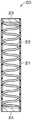
图1A是根据本技术的第一实施方式的致动器的示例性结构的透视图。图1B是处于预应变释放状态中的图1A的致动器的透视图。FIG. 1A is a perspective view of an exemplary structure of an actuator according to a first embodiment of the present technology. FIG. 1B is a perspective view of the actuator of FIG. 1A in a pre-strained released state.
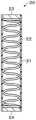
图2是根据本技术的第一实施方式的一种修改的致动器的示例性结构的透视图。FIG. 2 is a perspective view of an exemplary structure of an actuator according to a modification of the first embodiment of the present technology.
图3是根据本技术的第二实施方式的致动器的示例性结构的横截面视图。3 is a cross-sectional view of an exemplary structure of an actuator according to a second embodiment of the present technology.
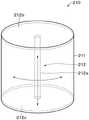
图4A是叠层的示例性结构的侧视图。图4B是沿着图4A中的线IVB-IVB的横截面视图。Figure 4A is a side view of an exemplary structure of a stack. FIG. 4B is a cross-sectional view along line IVB-IVB in FIG. 4A.
图5是根据本技术的第三实施方式的扬声器的示例性结构的透视图。5 is a perspective view of an exemplary structure of a speaker according to a third embodiment of the present technology.
图6是根据本技术的第四实施方式的扬声器的示例性结构的透视图。6 is a perspective view of an exemplary structure of a speaker according to a fourth embodiment of the present technology.
图7是示出了根据本技术的第五实施方式的内窥镜模块的示例性配置的框图。Fig. 7 is a block diagram showing an exemplary configuration of an endoscope module according to a fifth embodiment of the present technology.
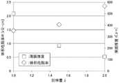
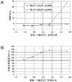
图8是示出了叠层的拉伸量、体积电阻率和薄膜厚度之间的关系的图表。FIG. 8 is a graph showing the relationship between the amount of stretch, volume resistivity, and film thickness of a laminate.
图9是根据本技术的第六实施方式的致动器在高度方向上的横截面视图。9 is a cross-sectional view in the height direction of an actuator according to a sixth embodiment of the present technology.
图10是根据本技术的第六实施方式的致动器在与高度方向垂直的方向上的横截面视图。10 is a cross-sectional view of an actuator in a direction perpendicular to a height direction according to a sixth embodiment of the present technology.
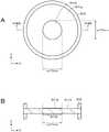
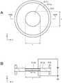
图11A是根据本技术的第七实施方式的致动器的示例性结构的平面视图。图11B是沿着图11A中的线XIB-XIB的横截面视图。11A is a plan view of an exemplary structure of an actuator according to a seventh embodiment of the present technology. FIG. 11B is a cross-sectional view along line XIB-XIB in FIG. 11A .
图12是根据本技术的第八实施方式的触觉演示装置的示例性结构的平面视图。12 is a plan view of an exemplary structure of a tactile presentation device according to an eighth embodiment of the present technology.
图13A和13B分别示出了根据本技术的第八实施方式的触觉演示装置的示例性操作的侧视图。13A and 13B are side views illustrating exemplary operations of the haptic demonstration device according to the eighth embodiment of the present technology, respectively.
图14是根据本技术的第八实施方式的一种修改的触觉演示装置的示例性结构的平面视图。14 is a plan view of an exemplary structure of a tactile presentation device according to a modification of the eighth embodiment of the present technology.
图15是根据本技术的第九实施方式的机器人的示例性结构的示意图。Fig. 15 is a schematic diagram of an exemplary structure of a robot according to a ninth embodiment of the present technology.
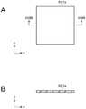
图16A是示出了生产样本5-1到5-5的致动器的步骤的平面视图。图16B是示出了生产样本6-1到6-5的致动器的步骤的平面视图。Fig. 16A is a plan view showing the steps of producing the actuators of samples 5-1 to 5-5. Fig. 16B is a plan view showing the steps of producing the actuators of samples 6-1 to 6-5.
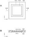
图17A是示出了生产样本5-1到5-5以及6-1到6-5的致动器的步骤的平面视图。图17B是沿着图17A中的线XVIIB-XVIIB的横截面视图。Fig. 17A is a plan view showing the steps of producing the actuators of samples 5-1 to 5-5 and 6-1 to 6-5. Fig. 17B is a cross-sectional view along line XVIIB-XVIIB in Fig. 17A.
图18A是示出了生产样本5-1到5-5以及6-1到6-5的致动器的步骤的平面视图。图18B是沿着图18A中的线XVIIB-XVIIB的横截面视图。Fig. 18A is a plan view showing the steps of producing the actuators of samples 5-1 to 5-5 and 6-1 to 6-5. Fig. 18B is a cross-sectional view along line XVIIB-XVIIB in Fig. 18A.
图19A是施加电压时样本5-1到5-5以及6-1到6-5的致动器的平面视图。图19B是沿着图19A中的线XIXB-XIXB的横截面视图。Fig. 19A is a plan view of actuators of samples 5-1 to 5-5 and 6-1 to 6-5 when a voltage is applied. Fig. 19B is a cross-sectional view along line XIXB-XIXB in Fig. 19A.
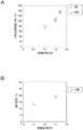
图20A是示出了双轴拉伸比率与刚度之间的关系的图表。图20B是示出了双轴拉伸比率与介质击穿强度之间的关系的图表。FIG. 20A is a graph showing the relationship between biaxial stretch ratio and stiffness. FIG. 20B is a graph showing the relationship between biaxial stretch ratio and dielectric breakdown strength.
图21A是示出了单轴拉伸比率与刚度之间的关系的图表。图21B是示出了单轴拉伸比率与介质击穿强度之间的关系的图表。FIG. 21A is a graph showing the relationship between uniaxial stretch ratio and stiffness. FIG. 21B is a graph showing the relationship between uniaxial stretch ratio and dielectric breakdown strength.
图22A是示出了生产样本7-1到7-3的致动器的步骤的平面视图。图22B是沿着图22A中的线XXIIB-XXIIB的横截面视图。Fig. 22A is a plan view showing the steps of producing the actuators of samples 7-1 to 7-3. Fig. 22B is a cross-sectional view along line XXIIB-XXIIB in Fig. 22A.
图23A是示出了生产样本7-1到7-3的致动器的步骤的平面视图。图23B是沿着图23A中的线XXIIIB-XXIIIB的横截面视图。Fig. 23A is a plan view showing the steps of producing the actuators of samples 7-1 to 7-3. Fig. 23B is a cross-sectional view along line XXIIIB-XXIIIB in Fig. 23A.
图24是示出了样本7-1到7-3中使用的纳米碳的类型与电阻率之间的关系的图表。Fig. 24 is a graph showing the relationship between the type of nanocarbon used in Samples 7-1 to 7-3 and the resistivity.
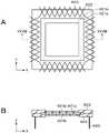
图25A是示出了用于评估样本8-1到8-4的致动器的传导率的方法的平面视图。图25B是沿着图25A中的线XXVB-XXVB的横截面视图。Fig. 25A is a plan view showing a method for evaluating the conductance of the actuators of the samples 8-1 to 8-4. Fig. 25B is a cross-sectional view along line XXVB-XXVB in Fig. 25A.
图26A是示出了用于评估样本8-1到8-4的致动器的传导率的方法的平面视图。图26B是沿着图26A中的线XXVIB-XXVIB的横截面视图。Fig. 26A is a plan view showing a method for evaluating the conductance of the actuators of the samples 8-1 to 8-4. Fig. 26B is a cross-sectional view along line XXVIB-XXVIB in Fig. 26A.
图27A是示出了用于评估样本8-1到8-4的致动器的传导率的方法的平面视图。图27B是沿着图27A中的线XXVIIB-XXVIIB的横截面视图。Fig. 27A is a plan view showing a method for evaluating the conductance of the actuators of the samples 8-1 to 8-4. Fig. 27B is a cross-sectional view along line XXVIIB-XXVIIB in Fig. 27A.
图28A是示出了用于评估样本8-1到8-4的致动器的传导率的方法的平面视图。图28B是沿着图28A中的线XXVIIIB-XXVIIIB的横截面视图。Fig. 28A is a plan view showing a method for evaluating the conductance of the actuators of samples 8-1 to 8-4. Fig. 28B is a cross-sectional view along line XXVIIIB-XXVIIIB in Fig. 28A.
图29A是示出了拉伸比率与电阻率之间的关系的图表。图29B是示出了由拉升造成的面积变化与电阻率之间的关系的图表。FIG. 29A is a graph showing the relationship between stretch ratio and resistivity. FIG. 29B is a graph showing the relationship between area change due to pull-up and resistivity.
图30A是示出了双轴拉伸比率与介质击穿强度之间的关系的图表。图30B是示出了双轴拉伸比率与面积变化之间的关系的图表。FIG. 30A is a graph showing the relationship between biaxial stretch ratio and dielectric breakdown strength. FIG. 30B is a graph showing the relationship between the biaxial stretch ratio and the change in area.
具体实施方式Detailed ways
在本技术中,叠层至少在一个方向上承受50%或更大的预应变。更具体地,叠层在一个方向或两个方向上承受50%或更大的预应变。在叠层在两个方向上承受预应变的情况下,一个方向上的预应变可以与另一个方向上的预应变相同或不同。在叠层在两个方向上承受预应变的情况下,其中一个方向可以与另一个方向正交或者不正交。In the present technique, the laminate is pre-strained by 50% or more in at least one direction. More specifically, the laminate is subjected to a pre-strain of 50% or more in one or both directions. Where the laminate is prestrained in two directions, the prestrain in one direction may be the same or different than the prestrain in the other direction. Where the laminate is pre-strained in two directions, one of the directions may or may not be orthogonal to the other.
叠层的形状示例包括但不局限于平坦形状、管状形状诸如圆管状、螺旋形形状、球形形状、弯曲形状等。弯曲形状的示例包括但不局限于部分球形形状、部分圆柱形形状等等。Examples of shapes of laminates include, but are not limited to, flat shapes, tubular shapes such as round tubes, helical shapes, spherical shapes, curved shapes, and the like. Examples of curved shapes include, but are not limited to, part spherical shapes, part cylindrical shapes, and the like.
叠层主表面的形状示例包括但不局限于圆形、椭圆形、多边形(例如四边形、六边形、八边形等)以及不规则形状。Examples of shapes of the major surfaces of the laminate include, but are not limited to, circles, ellipses, polygons (eg, quadrilaterals, hexagons, octagons, etc.), and irregular shapes.
将按照下面的顺序描述本技术的实施方式。Embodiments of the present technology will be described in the following order.
1 第一实施方式(示例性致动器)1 First Embodiment (Exemplary Actuator)
2 第二实施方式(示例性致动器)2 Second Embodiment (Exemplary Actuator)
3 第三实施方式(示例性扬声器)3 Third Embodiment (Exemplary Speaker)
4 第四实施方式(示例性扬声器)4 Fourth Embodiment (Exemplary Speaker)
5 第五实施方式(示例性内窥镜模块)5 Fifth Embodiment (Exemplary Endoscope Module)
6 第六实施方式(示例性致动器)6 Sixth Embodiment (Exemplary Actuator)
7 第七实施方式(示例性致动器)7 Seventh Embodiment (Exemplary Actuator)
8 第八实施方式(示例性触觉演示装置)8 Eighth Embodiment (Exemplary Haptic Demonstration Device)
9 第九实施方式(示例性机器人)9 Ninth Embodiment (Exemplary Robot)
<1第一实施方式><1 first embodiment>
【致动器的结构】【Structure of Actuator】
根据本技术的第一实施方式的致动器10是所谓的介电弹性体致动器。如图1A中所示,致动器10包括具有矩形薄片形状的叠层11。叠层11包括多个弹性电极11a和多个弹性弹性体层(介电层)11b。电极11a和弹性体层11b在叠层11的厚度方向上交替彼此堆叠。该第一实施方式示出了叠层11的主要表面是矩形的情形,但是叠层11的主要表面并不局限于这种形状。在下面的描述中,与叠层11的主要表面的两对相对的侧面中的其中一对平行的方向称作x轴方向(第一方向),与另一对平行的方向称作y轴方向(第二方向)。The
根据第一实施方式的致动器10安装在例如诸如人造肌肉和内窥镜之类的医疗装置、工业装置、人造色素体、天线、电子装置、声换能器(扬声器等)、康复装置、机器人、机器服、微型装置、振动装置(触觉演示装置等)、图像稳定模块或振荡器中。电子装置的示例包括但不限于个人计算机、移动装置、移动电话、平板电脑、显示器、成像装置、音频装置、游戏装置等。The
致动器10可以优选地由100V或更大以及4kV或更小的驱动电压驱动。如下所述,弹性体层11b可以在用于制造根据第一实施方式的致动器的方法中变薄,因为在成型之后要在x轴方向和y轴方向上拉伸叠层11。因此,致动器10可以由如上所述的低电压驱动。The
叠层11在x轴方向和y轴方向上均承受50%或更大的预应变(见图1A和图1B)。x轴方向上的预应变可以与y轴方向上的预应变相同或不同。x和y轴方向上各自的预应变优选80%或更大,更优选100%或更大。x和y轴方向上各自的预应变的上限优选1000%或更小,更优选500%或更小。The laminate 11 is pre-strained by 50% or more in both the x-axis direction and the y-axis direction (see FIGS. 1A and 1B ). The pre-strain in the x-axis direction may be the same or different from the pre-strain in the y-axis direction. The respective prestrains in the x- and y-axis directions are preferably 80% or more, more preferably 100% or more. The upper limit of each prestrain in the x- and y-axis directions is preferably 1000% or less, more preferably 500% or less.
预应变是从下面的公式中获得的。The prestrain is obtained from the formula below.
x轴方向上的预应变[%]=((Lx-L0x)/L0x)×100Pre-strain in the x-axis direction [%]=((Lx-L0x)/L0x)×100
y轴方向上的预应变[%]=((Ly-L0y)/L0y)×100Pre-strain in the y-axis direction [%]=((Ly-L0y)/L0y)×100
在公式中,Lx、L0x、Ly和L0y表示如下物理特性的值。In the formulas, Lx, L0x, Ly, and L0y represent the values of the following physical properties.
Lx:在预应变状态下x轴方向上叠层11的侧面的长度(见图1A)Lx: the length of the side of the laminate 11 in the x-axis direction in the pre-strained state (see Figure 1A)
L0x:在预应变释放状态下x轴方向上叠层11的侧面的长度(见图1B)L0x: the length of the side of the
Ly:在预应变状态下y轴方向上叠层11的侧面的长度(见图1A)Ly: the length of the side of the laminate 11 in the y-axis direction in the pre-strained state (see Figure 1A)
L0y:在预应变释放状态下y轴方向上叠层11的侧面的长度(见图1B)L0y: the length of the side of the laminate 11 in the y-axis direction in the pre-strain release state (see Figure 1B)
需要注意的是Lx、L0x、Ly和L0y均是在室温(23℃)下测量到的值。It should be noted that Lx, L0x, Ly, and L0y are all values measured at room temperature (23° C.).
(弹性体层)(elastomer layer)
弹性体层11b是弹性薄片。为了降低驱动电压,在预应变状态下弹性体层11b的平均厚度优选10μm或更小,更优选5μm或更小,还更优选3μm或更小。需要注意的是,在仅通过涂覆和干燥工艺形成弹性体层的已知方法中,难以形成具有10μm或更小的平均厚度的弹性体层。在预应变状态下弹性体层11b的平均厚度的下限并不受限,而是例如300nm或更大。The
为了降低驱动电压,处于预应变释放状态下的弹性体层11b的平均厚度优选40μm或更小,更优选20μm或更小,还更优选12μm或更小。在预应变释放状态下弹性体层11b的平均厚度的下限并不受限,而是例如1μm或更大。In order to reduce the driving voltage, the average thickness of the
弹性体层11b的平均厚度是正如下面所述的那样的获得的。首先,通过使用聚焦离子束(FIB)方法等对叠层11进行处理以形成横截面,利用扫描电子显微镜(SEM)捕获横截面图像(下文称作“横截面SEM图像”)。接下来,在随机选择的十个点的每个点处测量其中一个弹性体层11b在横截面SEM图像上的厚度,简单地将测量结果进行平均来获得弹性体层11b的平均厚度(算术平均)。The average thickness of the
弹性体层11b的杨氏模量优选10MPa或更小,更优选0.05MPa或更大以及10MPa或更小,还更优选0.1MPa或更大以及1MPa或更小。杨氏模量是根据JIS K 6251:2010确定的值。10MPa或更小的杨氏模量使得容易对弹性体层11b进行拉伸。此外,0.05MPa或更大的杨氏模量使得容易操纵弹性体层11b。弹性体层11b的断裂应变优选200%或更大,更优选200%或更大以及1200%或更小。200%或更大的断裂应变能够实现大的拉伸量。断裂应变是根据例如JIS K6251:2010测量的。The Young's modulus of the
弹性体层11b包含例如作为绝缘弹性材料的绝缘弹性体。弹性体层11b可以根据需要包含添加剂。该添加剂例如是交联剂、增塑剂、抗老化剂、表面活化剂、粘度调节剂、增强剂、着色剂等中的至少一种。绝缘弹性体包含丙烯酸橡胶、硅橡胶、三元乙丙橡胶(EPDM)、天然橡胶(NR)、丁基橡胶(IIR)、异戊二烯橡胶(IR)、丙烯腈/丁二烯橡胶(NBR)、加氢丙烯腈/丁二烯橡胶(H-NBR)、醇基橡胶、氯丁二烯橡胶(CR)、氟硅橡胶、聚氨酯橡胶等中的至少一种。为了具有良好的传导性,绝缘弹性体优选地没有诸如氧化钛或氧化硅之类的添加剂。The
(电极)(electrode)
电极11a具有弹性。具有弹性的电极11a可以在驱动致动器10时随着弹性体层11b的变形而变形。此外,如下所述,在拉伸叠层11时电极11a可以随着弹性体层11b的变形而变形。The
电极11a例如是固体、胶体或液体。电极11a可以由薄膜形成,或者不用粘结剂而承载在弹性体11b表面上的导电材料形成。电极11a可以设置在弹性体层11b的整体表面或者基本整个表面上,或者可以设置在弹性体层11b的表面的一部分上以便于形成预定的样式。图1A示出了后一示例。预定样式的示例包括但不局限于条纹、网格、螺旋、同心、网眼、几何样式等。The
在预应变释放状态中电极11a的平均厚度优选50μm或更小,更优选5μm或更小,还更优选3μm或更小。预应变释放状态中电极11a的平均厚度的下限不受限,而是例如300nm或更大。电极11a的平均厚度是以弹性体层11b的平均厚度相同的方式的获得的。The average thickness of the
电极11a的杨氏模量优选10MPa或更小,更优选0.05MPa或更大以及10MPa或更小,还更优选0.1MPa或更大以及1MPa或更小。杨氏模量是根据JIS K6251:2010确定的值。10MPa或更小的杨氏模量使得容易对电极11a进行拉伸。此外,0.05MPa或更大的杨氏模量使得容易操纵电极11a。电极11a的断裂应变优选200%或更大,更优选200%或更大以及1200%或更小。200%或更大的断裂应变能够实现大的拉伸量。断裂应变是根据例如JIS K 6251:2010测量的。The Young's modulus of the
在叠层11承受100%或更大的应变的情况下电极11a的体积电阻率优选10MΩ·cm或更小。因此,甚至在叠层11承受100%或更大的应变的情况下,电极11a可以起到具有良好传导性的电极的作用。应变的上限不受限制,但是优选1000%或更小,更优选500%或更小。电极11a的体积电阻率是根据JIS K7194-1994通过四端子方法获得的值。在根据JIS K5600-5-6:1999进行的横切测试中,电极11a与弹性体层11b之间的粘着力优选地额定为1到2中的任一标度,由于弹性体层11b与电极11a之间的刚度的差异在将叠层11大程度拉伸以便于承受50%或更大的预应变之后不可能发生弹性体层11b与电极11a之间的剥离。The volume resistivity of the
电极11a包含导电材料。电极11a根据需要还可以包括弹性粘合剂、胶体、悬胶或油中的至少一种。此外,电极11a根据需要还可以包含添加剂。The
导电材料例如是导电填料或导电聚合物中的至少一种。导电填料的形状示例包括但不限于球、椭圆、针、板、标尺、管、线、条(杆)、纤维、不规则形状等。需要注意的是可以单独使用具有一种形状的导电填料或者将具有两种或多种形状的导电填料结合使用。The conductive material is, for example, at least one of conductive filler or conductive polymer. Examples of shapes of conductive fillers include, but are not limited to, spheres, ellipses, pins, plates, scales, tubes, wires, strips (rods), fibers, irregular shapes, and the like. It is to be noted that conductive fillers having one shape may be used alone or conductive fillers having two or more shapes may be used in combination.
导电填料包含例如碳基填料、金属基填料、金属氧化物基填料或者金属涂层填料中的至少一种。这里,金属包括半金属。The conductive filler includes, for example, at least one of carbon-based fillers, metal-based fillers, metal oxide-based fillers, or metal-coated fillers. Here, metals include semimetals.
碳基填料包含例如碳黑(例如科琴黑、乙炔黑等)、多孔碳、碳纤维(例如PAN基碳纤维、沥青基碳纤维等)、碳纳米纤维、富勒烯、石墨烯、气相生长碳纤维(VGCF)、碳纳米管(例如SWCNT、MWCNT等)、碳微弹簧圈或者碳纳米角中的至少一种。Carbon-based fillers include, for example, carbon black (such as Ketjen black, acetylene black, etc.), porous carbon, carbon fibers (such as PAN-based carbon fibers, pitch-based carbon fibers, etc.), carbon nanofibers, fullerenes, graphene, vapor grown carbon fibers (VGCF ), carbon nanotubes (such as SWCNT, MWCNT, etc.), carbon microcoils or carbon nanohorns.
金属基填料包含例如铜、银、金、铂、钯、镍、锡、钴、铑、铱、铁、钌、锇、锰、钼、钨、铌、钽、钛、铋、锑或铅中的至少一种。Metal-based fillers containing, for example, copper, silver, gold, platinum, palladium, nickel, tin, cobalt, rhodium, iridium, iron, ruthenium, osmium, manganese, molybdenum, tungsten, niobium, tantalum, titanium, bismuth, antimony, or lead at least one.
金属氧化物基填料包含例如铟锡氧化物(ITO)、氧化锌、氧化铟、掺锑氧化锡、掺氟氧化锡、掺铝氧化锌、掺镓氧化锌、掺硅氧化锌、氧化锌-氧化锡、氧化铟-氧化锡或者氧化锡-氧化铟-氧化锰。Metal oxide-based fillers include, for example, indium tin oxide (ITO), zinc oxide, indium oxide, antimony-doped tin oxide, fluorine-doped tin oxide, aluminum-doped zinc oxide, gallium-doped zinc oxide, silicon-doped zinc oxide, zinc oxide-oxide Tin, indium oxide-tin oxide or tin oxide-indium oxide-manganese oxide.
金属涂层填料是包括涂覆有金属的基础填料的填料。基础填料的示例包括云母、玻璃珠、玻璃纤维、碳纤维、碳化钙、氧化锡和氧化钛。覆盖基础填料的金属包含例如Ni或Al中的至少一种。Metal-coated fillers are fillers that include a base filler coated with a metal. Examples of base fillers include mica, glass beads, glass fibers, carbon fibers, calcium carbide, tin oxide, and titanium oxide. The metal covering the base filler contains, for example, at least one of Ni or Al.
导电填料的平均尺寸优选35nm或更大以及37nm或更小。这是因为获得了具有突出传导性的电极11a。这里,以如下方式获得该平均尺寸。首先,使用扫描电子显微镜(SEM)捕获导电填料的SEM图像。接着,通过使用图像分析软件来测量在SEM图像中随机选择的10片导电填料的每片的尺寸。这里,导电填料的尺寸意思是所谓的最大Feret直径,具体地,意思是以给定角度画出的并且与导电填料的轮廓相切的两条平行线之间的最大距离。The average size of the conductive filler is preferably 35 nm or more and 37 nm or less. This is because the
导电聚合物是例如聚乙撑二氧噻吩/聚磺苯乙烯(PEDOT/PSS)、聚苯胺、聚乙炔或聚吡咯中的至少一种。The conductive polymer is, for example, at least one of polyethylenedioxythiophene/polystyrenesulfonate (PEDOT/PSS), polyaniline, polyacetylene, or polypyrrole.
粘合剂优选是弹性体。弹性体的示例包括与弹性体层11b中的那些弹性体相同的弹性体。添加剂的示例包括与弹性体层中的那些添加剂相同的添加剂。The binder is preferably an elastomer. Examples of the elastic body include the same elastic bodies as those in the
电极11a可以包含复合材料(复杂材料)。该复合材料包含例如含有弹性体和导电聚合物或导电填料中的至少一种的复合材料、含有弹性离子导电材料和电解液的复合材料、含有聚合物悬胶(丙烯酸乳液等)和导电聚合物或导电填料中的至少一种的复合物、含有嵌段共聚物和导电聚合物或导电填料中的至少一种的复合物或者含有聚合物胶体和离子导体的复合物中的至少一种。The
(粘着力的改进)(adhesion improvement)
弹性体层11b与电极11a之间的界面优选地进行粘着力改进处理。在改进粘着力的情况下,在对叠层11大程度拉伸以便于承受50%或更大的预应变之后不会发生由于弹性体层11b与电极11a之间的刚度差异而导致的弹性体层11b与电极11a之间的剥离。The interface between the
为了改进界面的粘着力,叠层11优选地包括以下中的至少一个:(1)设置在弹性体层11b与电极11a之间的硅烷偶联剂、(2)设置在弹性体层11b与电极11a之间的基层处理剂层、(3)弹性体层11b或电极11a中的至少一个的物理上预处理的表面、或者(4)弹性体层11b或电极11a中的至少一个的锐利的不均匀表面。需要注意的是物理预处理是例如准分子光辐射处理、紫外线辐射处理、等离子处理或者电晕处理中的至少一种。In order to improve the adhesion of the interface, the laminate 11 preferably includes at least one of the following: (1) a silane coupling agent disposed between the
(硅烷偶联剂)(A silane coupling agent)
硅烷偶联剂的类型并没有具体限制,允许使用任何已知的硅烷偶联剂。硅烷偶联剂的具体里示例包括乙烯基三氯硅烷、乙烯基三甲氧基硅烷、乙烯基三乙氧基硅烷、2-(3,4-环氧环己基)乙基三甲氧基硅烷、3-(2,3-环氧丙氧)丙基三甲氧基硅烷、3-缩水甘油醚氧基丙基甲基二乙氧基硅烷、3-缩水甘油醚氧基丙基三乙氧基硅烷、(4-乙烯基苯基)三甲氧基硅烷、3-甲基丙烯酰氧基丙基甲基二甲氧基硅烷、3-(甲基丙烯酰氧)丙基三甲氧基硅烷、甲基丙烯酰氧基丙基甲基二乙氧基硅烷、甲基丙烯酰氧基丙基三乙氧基硅烷、3-三甲氧基硅烷丙烯酸丙酯、N-氨乙基-3-氨丙基甲基二甲氧基硅烷、N-(2-氨乙基)-3-氨丙基三甲氧基硅烷、N-氨乙基-3-氨丙基三乙氧基硅烷、3-氨丙基三甲氧基硅烷、3-氨基丙基三乙氧基硅烷、3-(1,3-二甲基丁烯)氨丙基三乙氧基硅烷、N-苯基-3-氨基丙基三甲氧基硅烷、乙烯基苄基氨乙基氨丙基三甲氧基硅烷的盐酸盐、3-脲基丙基三乙氧基硅烷、3-氯丙基三甲氧基硅烷、巯丙基甲基二甲氧基硅烷、巯丙基三甲氧基硅烷、双-[3-(三乙氧基硅)丙基]-四硫化物和3-异氰酸酯基三乙氧基硅烷。The type of silane coupling agent is not particularly limited, and any known silane coupling agent is allowed to be used. Specific examples of the silane coupling agent include vinyltrichlorosilane, vinyltrimethoxysilane, vinyltriethoxysilane, 2-(3,4-epoxycyclohexyl)ethyltrimethoxysilane, 3 -(2,3-Glycidoxy)propyltrimethoxysilane, 3-Glycidoxypropylmethyldiethoxysilane, 3-Glycidoxypropyltriethoxysilane, (4-vinylphenyl)trimethoxysilane, 3-methacryloxypropylmethyldimethoxysilane, 3-(methacryloxy)propyltrimethoxysilane, methacrylic Acyloxypropylmethyldiethoxysilane, Methacryloxypropyltriethoxysilane, 3-Trimethoxysilane Propyl Acrylate, N-Aminoethyl-3-Aminopropylmethyl Dimethoxysilane, N-(2-aminoethyl)-3-aminopropyltrimethoxysilane, N-aminoethyl-3-aminopropyltriethoxysilane, 3-aminopropyltrimethoxy 3-aminopropyltriethoxysilane, 3-(1,3-dimethylbutenyl)aminopropyltriethoxysilane, N-phenyl-3-aminopropyltrimethoxysilane , Vinylbenzylaminoethylaminopropyltrimethoxysilane hydrochloride, 3-ureidopropyltriethoxysilane, 3-chloropropyltrimethoxysilane, mercaptopropylmethyldimethoxysilane methoxysilane, mercaptopropyltrimethoxysilane, bis-[3-(triethoxysilyl)propyl]-tetrasulfide and 3-isocyanatotriethoxysilane.
【致动器的操作】【Operation of Actuator】
接下来,将要描述根据本技术的第一实施方式的致动器10的示例性操作。Next, an exemplary operation of the
当在彼此面对且之间具有弹性体层11b的电极11a和11a上施加驱动电压时,由于库仑力而在电极11a与11a之间产生吸引力。因此,在厚度方向上对设置于电极11a与11a之间的弹性体层11b进行施压以便于使其变薄并将其拉长。When a driving voltage is applied to the
另一方面,当在彼此面对且之间具有弹性体层11b的电极11a和11a上释放驱动电压时,由于库仑力而在电极11a与11a之间不产生吸引力。因此,弹性体层11b由于其回弹力而恢复到其原始厚度并且收缩到其原始尺寸。On the other hand, when the driving voltage is released on the
【制造致动器的方法】【Method of Manufacturing Actuator】
接下来,将要描述制造根据本技术的第一实施方式的致动器10的示例性方法。Next, an exemplary method of manufacturing the
(制备导电涂层材料的步骤)(Procedure for preparing conductive coating material)
通过在溶剂中分散导电材料来制备作为用于形成电极的涂层材料的导电涂层材料。根据需要,可以进一步将粘合剂或添加剂中的至少一种添加到溶剂中。例如,根据需要可以添加诸如表面活性剂、粘度调节剂和分散剂之类的添加剂以便于提高导电涂层材料在弹性体层11b上的涂布性能和活化期。导电涂层材料可以是导电油墨或者可以是导电胶。分散方法优选地包括例如搅拌、超声分散、珠分散、揉捏或均质器处理。A conductive coating material as a coating material for forming electrodes is prepared by dispersing a conductive material in a solvent. At least one of a binder or an additive may be further added to the solvent as needed. For example, additives such as surfactants, viscosity modifiers, and dispersants may be added as needed in order to improve coating performance and pot life of the conductive coating material on the
溶剂可以是极性溶剂或非极性溶剂,但是优选非极性溶剂。溶剂是可以分散导电材料的任何溶剂。溶剂的示例包括水、甲苯、乙酸乙酯、乙醇、甲乙酮、异丙醇、丙酮、环己醇(环己酮、环戊酮)、碳氢化合物(己烷)、氨基化合物(DMF)、硫化物(DMSO)、丁基溶纤剂、三聚乙二醇单丁醚、丙二醇单甲醚、丙二醇单乙醚、乙二醇单乙醚、乙二醇单丙基醚、乙二醇单异丙基醚、二乙二醇丁醚、二甘醇单乙醚、二乙二醇甲醚、二乙二醇二乙醚、二丙二醇单甲醚、三丙二醇单甲醚、丙二醇丁醚、丙二醇异丙醚、二丙二醇异丙醚、三丙二醇异丙醚、甲基乙二醇、松油醇、二乙二醇丁醚醋酸酯。具体地,导电涂层材料优选地包含碳基填料、硅树脂和非极性溶剂。The solvent may be a polar solvent or a non-polar solvent, but a non-polar solvent is preferred. A solvent is any solvent that can disperse the conductive material. Examples of solvents include water, toluene, ethyl acetate, ethanol, methyl ethyl ketone, isopropanol, acetone, cyclohexanol (cyclohexanone, cyclopentanone), hydrocarbons (hexane), amino compounds (DMF), sulfide (DMSO), butyl cellosolve, tripolyethylene glycol monobutyl ether, propylene glycol monomethyl ether, propylene glycol monoethyl ether, ethylene glycol monoethyl ether, ethylene glycol monopropyl ether, ethylene glycol monoisopropyl ether, Diethylene glycol butyl ether, diethylene glycol monoethyl ether, diethylene glycol methyl ether, diethylene glycol diethyl ether, dipropylene glycol monomethyl ether, tripropylene glycol monomethyl ether, propylene glycol butyl ether, propylene glycol isopropyl ether, dipropylene glycol Isopropyl Ether, Tripropylene Glycol Isopropyl Ether, Methyl Glycol, Terpineol, Diethylene Glycol Butyl Ether Acetate. Specifically, the conductive coating material preferably contains carbon-based fillers, silicone resins, and nonpolar solvents.
(制备用于形成弹性体层的涂层材料的步骤)(Procedure of preparing coating material for forming elastomer layer)
通过将弹性体分散在溶剂中来制备用于形成弹性体层的涂层材料。根据需要,除了弹性体之外可以进一步将添加剂或树脂材料中的至少一种添加到溶剂中。例如,根据需要可以添加诸如表面活性剂、粘度调节剂和分散剂之类的添加剂以便于提高弹性体层结构的涂层材料在电极11a上的涂布性能和活化期。分散处理的示例包括与在制备导电涂层材料的步骤中描述的相同的那些处理。溶剂是可以分散弹性体的任何溶剂。溶剂的示例包括与在制备导电涂层材料的步骤中描述的那些溶剂相同的溶剂。The coating material for forming the elastomer layer is prepared by dispersing the elastomer in a solvent. According to need, at least one of an additive or a resin material may be further added to the solvent in addition to the elastomer. For example, additives such as surfactants, viscosity modifiers, and dispersants may be added as needed in order to improve the coating performance and pot life of the coating material of the elastomer layer structure on the
(生产叠层的步骤)(Steps to produce stackup)
以如下方式生产叠层11。首先,提供基板,根据需要对基板的表面进行剥离处理。基板可以是无机基板或塑料基板。基板具有例如板材形状或片材形状。
接下来,将导电涂层材料涂覆到基板的一个表面以形成涂层薄膜。这里涂覆包括印刷。涂覆方法的示例包括但不局限于密纹涂层方法、线棒涂层方法、直接凹版涂布法、模具涂布方法、浸涂方法、喷涂方法、逆转辊涂布方法、幕式涂覆法、逗号涂布法、刮刀涂布法、旋转涂布法、喷墨印刷法、凸版印刷法、胶版印刷法、凹版印刷法、雕刻印刷法、橡胶板印刷法、丝网印刷法和柔性版印刷法。Next, a conductive coating material is applied to one surface of the substrate to form a coating film. Coating here includes printing. Examples of coating methods include, but are not limited to, texture coating methods, wire bar coating methods, direct gravure coating methods, die coating methods, dip coating methods, spray coating methods, reverse roll coating methods, curtain coating methods method, comma coating method, knife coating method, spin coating method, inkjet printing method, letterpress printing method, offset printing method, gravure printing method, engraving printing method, rubber plate printing method, screen printing method and flexographic printing printing method.
随后,对成型在基板一个表面上的涂层薄膜进行干燥。干燥条件没有限制并且可以是自然干燥或者加热干燥。因此将电极11a成型在基板的一个表面上。接下来,根据需要可以对电极11a的一个表面进行粘着力改进处理。Subsequently, the coating film formed on one surface of the substrate is dried. Drying conditions are not limited and may be natural drying or heat drying. The
接着,将用于弹性体层结构的涂层材料涂覆到电极11a的一个表面以形成涂层薄膜。涂覆方法的示例包括与导电涂层材料的涂覆方法相同的涂覆方法。随后,对成型在基板一个表面上的涂层薄膜进行干燥。干燥条件没有限制并且可以自然干燥或者加热干燥。因此在电极11a的一个表面上形成弹性体层11b。接下来,根据需要可以对弹性体层11b的一个表面进行粘着力改进处理。Next, a coating material for the elastomer layer structure is applied to one surface of the
此后,交替重复成型电极11a的步骤和放置弹性体层11b的步骤以在基板的一个表面上形成分层产品。然后将整个分层产品从基板剥离,或者将分层产品从基板部分地剥离。从而获得叠层11。Thereafter, the step of molding the
(拉伸步骤)(stretch step)
随后,在x和y轴方向上对获得的叠层11进行拉伸(双轴拉伸)。从而使得叠层在x和y轴方向上承受50%或更大的预应变。在这种拉伸状态中,叠层11的周边可以由保持器保持。从而获得了所需的致动器10。Subsequently, the obtained
【有益效果】【Beneficial effect】
根据第一实施方式的致动器10包括叠层11,叠层11包括多个弹性弹性体层11b和多个弹性电极11a。弹性弹性体层11b和弹性电极11a彼此交替堆叠。叠层11在x和y轴方向上承受50%或更大的预应变。因此可以使弹性体层11b变薄以降低驱动电压。The
此外,因为根据第一实施方式的致动器10中的电极11a甚至能够在被大程度拉长时起到电极的功能,叠层11在成型后能够被大程度拉伸并且在x和y轴方向上承受50%或更大的预应变。另一方面,在典型的致动器中,电极相对于原始长度的一致性低到大约百分之几十,因此电极在被大程度拉长之后会失去它们作为电极的功能。因此难以对叠层进行大程度拉伸并且使叠层在x和y轴方向上承受50%或更大的预应变。In addition, because the
此外,在用于制造根据第一实施方式的致动器的方法中,通过涂覆工艺使电极11a和弹性体层11b彼此重复堆叠以形成叠层11,并且对叠层进行拉伸以提供叠层11。该方法可以形成包括弹性体层11b和电极11a的叠层11,且弹性体层11b和电极11a每个具有难以由一般的涂覆工艺获得的薄膜厚度。Furthermore, in the method for manufacturing the actuator according to the first embodiment, the
此外,因为在用于制造致动器的一般方法中,弹性体层是以单层的形式被操纵的,所以弹性体层的操纵能力小,或者致动器的制造效率低。另一方面,在用于制造根据第一实施方式的致动器的方法中,弹性体层11b是以叠层11而不是单层的形式被操纵的,从而可以提高弹性体层11b的操纵能力,可以高效率制造致动器10。此外,在将单层形式难以操纵的弹性体层11b堆叠的情况下,容易对弹性体层11b进行操纵,例如对弹性体层11b进行切割或叠合。还有,可以减小表面不均匀性的影响。Furthermore, since the elastomer layer is handled in a single layer in the general method for manufacturing an actuator, the handling ability of the elastomer layer is small, or the manufacturing efficiency of the actuator is low. On the other hand, in the method for manufacturing the actuator according to the first embodiment, the
【修改】【Revise】
(修改1)(modification 1)
如图2中所示,致动器10还可以包括保持单元12,其将叠层11保持在预应变状态。保持单元12保持叠层11的整个周边。保持单元12可以在x和y轴方向上拉伸,正如在图2中由箭头标示出的。换言之,保持单元12能够改变叠层12大小。通过改变叠层11大小可以调节叠层11上的预应变。As shown in Fig. 2, the
需要注意的是保持单元12具有任何结构,只要保持单元12可以对在x和y轴方向上承受预应变的叠层11进行保持即可。例如,保持单元12可以在不连续的位置上部分地保持叠层11的周边。此外,保持单元12可以提前设置在电子装置的壳体、框架等的上面。替代性地,通过将叠层11的周边等连接到电子装置的壳体、框架等,可以将叠层11保持在预应变状态。It should be noted that the holding
(修改2)(Modification 2)
可以将片状弹性体层11b放置在电极11a的一个表面上,而不是在电极11a的一个表面上涂覆并干燥用于形成弹性体层的涂层材料来形成弹性体层11b。这里,在放置弹性体层11b之前,可以对上面要放置弹性体层11b的电极11a的至少一个表面或者要放置在电极11a上的弹性体层11b的表面进行附着力改进处理。The
(修改3)(Modification 3)
弹性体层11b可以具有多层结构。在这种情况下,形成与电极11接触的表面的层可以由对电极11a具有高附着力的材料制成。The
(修改4)(Modification 4)
弹性体层11b的拉伸和应变特性可以使得弹性体层11b在拉伸之后的弹性模量优选地是0.05MPa或更大以及10MPa或更小,更优选0.1MPa或更大以及1MPa或更小,从拉伸状态进一步拉伸之后的杨氏模量快速增加到0.3MPa或更大或大约5MPa。The stretch and strain characteristics of the
(修改5)(Modification 5)
电极11a的至少部分是由杨氏模量超过10MPa的硬质材料制成的。例如,电极11a可以具有带有弹性的柔性部和弹性比柔性部更低的硬质部。硬质部优选地位于驱动段的容易断裂的部分。硬质部由例如金属等制成。At least part of the
电极11a可以具有弹性各向异性。具体地,电极可以在第一方向和第二方向上具有不同的弹性。例如,电极可以在第一方向上具有弹性,但是可以在第二方向上几乎没有弹性。The
第一实施方式阐述了整个叠层11承受预应变的情况,但是部分叠层11可以承受预应变。在这种情况系下,预应变是从下面的公式中得到的。The first embodiment explains the case where the
x轴方向上的预应变[%]=((Mx-M0x)/M0x)×100Pre-strain in the x-axis direction [%]=((Mx-M0x)/M0x)×100
y轴方向上的预应变[%]=((My-M0y)/M0y)×100Pre-strain in the y-axis direction [%]=((My-M0y)/M0y)×100
在公式中,Mx、M0x、My和M0y表示如下物理特征的值。In the formulas, Mx, M0x, My, and M0y represent the values of the following physical characteristics.
Mx:在预应变状态下预应变部分在x轴方向上的长度。Mx: the length of the pre-strained portion in the x-axis direction in the pre-strained state.
M0x:在预应变释放状态下预应变部分的侧面在x轴方向上的长度。M0x: the length in the x-axis direction of the side surface of the prestrained portion in the prestrained released state.
My:在预应变状态下预应变部分在y轴方向上的长度。My: the length of the pre-strained part in the y-axis direction in the pre-strained state.
M0y:在预应变释放状态下预应变部分的侧面在y轴方向上的长度。M0y: the length in the y-axis direction of the side surface of the prestrained portion in the prestrained released state.
需要注意的是Mx、M0x、My和M0y均是在室温(23℃)下测量的值。It should be noted that Mx, M0x, My and M0y are all values measured at room temperature (23°C).
<2第二实施方式><2 Second Embodiment>
【致动器的结构】【Structure of Actuator】
如图3中所示,根据本技术的第二实施方式的致动器20包括圆管状片状叠层21、支撑叠层21的内圆周表面的圆管状卷簧22以及封闭叠层11两端处开口的密封构件23和24。致动器20还可以包括覆盖叠层21的外圆周表面的圆管状保护层(未示出)。叠层21可以提前成型成圆管形状,或者可以缠绕在卷簧22周围以形成圆管形状。As shown in FIG. 3 , the
致动器20安装在例如诸如内窥镜之类的医疗装置、工业装置、电子装置、人工肌肉、机器人、机器服等中。致动器20可以连续使用或可以是一次性的。在致动器20用在诸如内窥镜之类的医疗装置中的情况下,出于卫生的原因致动器20优选地是一次性的。The
致动器20具有密封的圆柱形内部空间并且在该内部空间中具有卷簧22。内部空间填充有用作流体的气体。该气体例如是空气、惰性气体、二氧化碳等中的至少一种。The
下面将顺序描述致动器20中的叠层21、卷簧22、密封构件23和24以及保护层。The
(叠层)(stack)
正如在图4A和4B中由箭头标示出的,叠层21在叠层21的高度方向和圆周方向中均承受50%或更大的预应变。当叠层21的两端由密封构件23和24或卷簧22的两端保持时,叠层21被保持在预应变状态。高度方向上的预应变可以与圆周方向上的预应变相同或不同。高度方向和圆周方向上的预应变优选80%或更大,更优选100%或更大,还更优选120%或更大。高度方向和圆周方向上的预应变的上限优选400%或更小,更优选300%或更小。As indicated by the arrows in FIGS. 4A and 4B , the laminate 21 is subjected to a pre-strain of 50% or more in both the height direction and the circumferential direction of the laminate 21 . When both ends of the laminate 21 are held by the
预应变是从如下公式中得到的。The pre-strain is obtained from the following formula.
高度方向上的预应变[%]=((H-H0)/H0)×100Pre-strain in height direction [%]=((H-H0)/H0)×100
圆周方向上的预应变[%]=((C-C0)/C0)×100Pre-strain in the circumferential direction [%]=((C-C0)/C0)×100
H:预应变状态下圆管状叠层21的高度。H: the height of the circular
H0:预应变释放状态下圆管状叠层21的高度。H0: the height of the circular
C:预应变状态下圆管状叠层21的外圆周的长度。C: the length of the outer circumference of the circular
C0:预应变释放状态下圆管状叠层21的外圆周的长度。C0: the length of the outer circumference of the circular
需要注意的是H、H0、C和C0均是在室温(23℃)下测量的值。It should be noted that H, H0, C and C0 are all values measured at room temperature (23°C).
如图4A和图4B中所示,叠层21包括多个弹性电极21a和多个弹性弹性体层21b。电极21a和弹性体层21b在叠层21的径向方向上彼此交替堆叠。As shown in FIGS. 4A and 4B , the
(弹性体层)(elastomer layer)
弹性体层21b是圆管状薄片。弹性体层21b关于卷簧22彼此同心堆叠。替代性地,具有条带形状的弹性体层21b可以螺旋地缠绕在卷簧22的圆周面周围。弹性体层21b可以提前成型成圆管形状,或者可以缠绕在卷簧22周围以形成圆管形状。除了这些点外,弹性体层21b与第一实施方式中的弹性体层11b相同。The
(电极)(electrode)
电极21a在叠层21的高度方向上延伸并且在圆周方向方以规则间隔彼此间隔开。此外,电极21a在叠层21的径向方向上彼此重叠。换言之,弹性体层11b两侧上的电极21a彼此面对,它们之间具有弹性体层11b。除了这些点之外,电极21a与第一实施方式中的电极11a相同。The
(卷簧)(coil spring)
卷簧22是一示例性支撑件,其可以在任何方向上弯曲并且可以弹性变形。卷簧22是通过将诸如金属丝之类的线性构件缠绕成圆管状螺旋形而形成的卷簧。在线性构件的线匝之间形成空间。因此,卷簧22在叠层21的高度方向上分散地支撑叠层21的内圆周表面。以这种方式支撑叠层21的内圆周表面便于叠层21的变形并且便于致动器20的膨胀/收缩和弯曲。这里“在叠层21的高度方向上分散地支撑叠层21的内圆周表面”意思是在叠层21的高度方向上的不连续的位置上支撑叠层21的内圆周表面。这里,不连续位置之间的间隔可以是规则的或不规则的。The
(密封构件)(sealing member)
密封构件23和24具有盘形。密封构件23和24包含金属或聚合树脂。密封构件23和24可以包含弹性体等并且可以弹性变形。密封构件23和24可以是设置在致动器20的端部处的装置(例如电子装置,比如照相机),或者可以是致动器20的操作部。The sealing
(保护层)(The protective layer)
保护层旨在保护电极11a并且是弹性片材。保护层包含绝缘聚合树脂。聚合树脂的示例包括聚氯乙烯。The protective layer is intended to protect the
【致动器的操作】【Operation of Actuator】
接下来,将要描述根据本技术的第二实施方式的致动器20的示例性操作。Next, an exemplary operation of the
当在彼此面对且之间具有弹性体层21b的多对电极21a和21a中的一对电极21a和21a上施加驱动电压时,设置在该对电极21a与21a之间的弹性体层11b被拉长,因此致动器20弯曲。当施加到该对电极21a和21a的驱动电压释放时,致动器20恢复到其原始的圆柱形状。When a drive voltage is applied to a pair of
【制造致动器的方法】【Method of Manufacturing Actuator】
接下来,将要描述制造根据本技术的第二实施方式的致动器的示例性方法。Next, an exemplary method of manufacturing the actuator according to the second embodiment of the present technology will be described.
首先,将导电涂层材料和用于弹性体层结构的涂层材料交替地涂覆在圆管状基板的圆柱表面上并对其进行干燥。此后,将叠层整个从基板剥离,或者将叠层部分地从基板剥离,以获得叠层21。First, a conductive coating material and a coating material for an elastomer layer structure are alternately coated on a cylindrical surface of a round tubular substrate and dried. Thereafter, the laminate is entirely peeled from the substrate, or the laminate is partially peeled from the substrate to obtain a
接下来,在叠层21的高度方向和圆周方向上对叠层21进行拉伸(双轴拉伸)。从而使叠层21在高度方向和圆周方向上承受50%或更大的预应变。将卷簧22插入到预应变叠层21的内侧中。替代性地,在高度方向和圆周方向上对叠层21进行拉伸的同时可以将卷簧22插入到叠层21的内侧中。接下来,将密封构件23和24装到叠层21两端处的相应开口以将叠层21两端处的开口封闭。接下来,由密封构件23和24或者卷簧22的两端保持叠层21的两端。从而获得图3中示出的致动器20。Next, the laminate 21 is stretched in the height direction and the circumferential direction of the laminate 21 (biaxial stretching). Thus, the laminate 21 is subjected to a pre-strain of 50% or more in the height direction and the circumferential direction. A
【有益效果】【Beneficial effect】
根据第二实施方式的致动器20和用于制造致动器20的方法提供了与由根据第一实施方式的致动器10和用于制造致动器10的方法提供的有益效果相同的有益效果。The
【修改】【Revise】
(修改1)(modification 1)
第二实施方式阐述了电极21a设置在弹性体层21b的部分圆周表面上以形成预定样式的情况。然而,电极21a可以成型在弹性体层21b的整个圆周表面上。The second embodiment explains the case where the
(修改2)(Modification 2)
致动器20可以以如下方式制造。首先,以与第一实施方式中相同的方式获得条带形叠层21,不过导电涂层材料是以条带的方式涂覆的。需要注意的是,在将片材用作基板的情况下,可以通过卷装工艺生产叠层21。接下来,在高度方向和圆周方向上对叠层21进行拉伸的同时将叠层21缠绕在卷簧22的圆周面周围。接下来的步骤与第二实施方式中的相同。The
(修改3)(Modification 3)
叠层21的圆周方向上的预应变可以比叠层21的高度方向上的预应变更大。在这种情况下,可以提高叠层21对介电击穿的阻力同时保持叠层21在高度方向上的位移符合要求。The pre-strain in the circumferential direction of the
(修改4)(Modification 4)
叠层21可以在圆周方向上承受预应变,在高度方向上不承受预应变。在这种情况下,也可以提高叠层21对介电击穿的阻力同时保持叠层21在高度方向上的位移符合要求。The laminate 21 may be pre-strained in the circumferential direction and not pre-strained in the height direction. In this case, it is also possible to increase the resistance of the
<第三实施方式><Third Embodiment>
【扬声器的结构】【Structure of speaker】
如图5中所示,根据本技术的第三实施方式的扬声器110包括矩形致动器111和保持致动器111的周边部的保持单元112。致动器111与根据第一实施方式的致动器10相同。As shown in FIG. 5 , a
保持单元112以将致动器111(即叠层)弯曲成拱形并且在致动器111的弯曲方向和宽度方向(由图5中的箭头标示出的方向)上均承受50%或更大的预应变的方式保持致动器111。The holding
【有益效果】【Beneficial effect】
在根据第三实施方式的扬声器110中,致动器111(即叠层)在弯曲方向和宽度方向上均承受50%或更大的预应变。这种配置可以降低扬声器110的驱动电压。In the
<4第四实施方式><4 fourth embodiment>
【扬声器的结构】【Structure of speaker】
如图6中所示,根据本技术的第四实施方式的扬声器210包括圆管状薄片状致动器211和保持致动器211的两端部的保持单元。除了弹性体层和电极具有圆管形状之外,致动器211与根据第一实施方式的致动器相同。As shown in FIG. 6 , a
保持单元212包括轴212a和保持构件212b和212c,保持构件212b和212c具有盘形并且设置在轴212a的两端处。保持构件212b和212c以使致动器211在高度方向和圆周方向这两个方向中的每个方向上承受50%或更大预应变的方式将致动器111保持在圆管形状。The holding
【有益效果】【Beneficial effect】
在根据第四实施方式的扬声器210中,致动器211在高度方向和圆周方向上均承受50%或更大的预应变。这种配置可以降低扬声器210的驱动电压。In the
【修改】【Revise】
致动器211可以具有诸如四边形管形状之类的多边形管形状,保持构件212b和212c可以具有诸如四边形形状之类的多边形形状。The
<5第五实施方式><5 fifth embodiment>
如图7中所示,根据本技术的第五实施方式的内窥镜模块包括内窥镜310和控制器321。控制器321连接到电源323。需要注意的是,在第五实施方式中,与第二实施方式中相同的部件由相同的字符表示,并且省略对其的描述。As shown in FIG. 7 , the endoscope module according to the fifth embodiment of the present technology includes an
内窥镜310包括操作部311、是可弯曲部的致动器312、以及远端部313。操作部311具有用于操作内窥镜的按钮、旋钮等。The
致动器312包括叠层21和卷簧22。致动器312的内部空间被密封。致动器312的一个开口由远端部313封闭,另一端处的另一开口由操作部311封闭。远端部313的远端表面具有照明透镜和物镜(未示出)。除了照明透镜和物镜之外,远端部313的表面的一部分由例如不锈钢等制成。照明透镜和物镜例如是玻璃透镜。照明装置设置在照明透镜的内侧上。诸如电荷耦合装置(CCD)或互补金属氧化物半导体(CMOS)之类的成像装置设置在物镜的内侧上。成像装置经由图像处理器(未示出)连接到显示器(未示出)。The
远端部313和操作部311通过位于致动器312内部空间中的电缆彼此连接。操作信号从操作部311通过电缆发送到远端部313。此外,远端部313和图像处理器通过位于致动器312内部空间的电缆彼此连接。视频信号经由该电缆从远端部313发送到图像处理器。然而,操作部311可以向远端部313无线发送信号,远端部313可以向图像处理器无线发送视频信号。The
控制器321基于从操作部311发送的控制信号控制弯曲驱动电路322。弯曲驱动电路322基于从控制器321发送的控制信号使致动器312弯曲。弯曲驱动电路322可以设置在操作部311中。The
【有益效果】【Beneficial effect】
在根据第五实施方式的内窥镜模块中,致动器312包括圆管状叠层21,其在高度方向和圆周方向上承受50%或更大的预应变。这种配置可以降低内窥镜模块的驱动电压。In the endoscope module according to the fifth embodiment, the
<6第六实施方式><6 sixth embodiment>
【致动器的结构】【Structure of Actuator】
如图9中所示,根据本技术第六实施方式的致动器30包括圆管状叠层31、支撑叠层31内圆周表面的圆管状卷簧22、封闭叠层21两端处开口的密封构件23和24。需要注意的是在第六实施方式中,与第二实施方式中相同的部件由相同的部件由相同的字符表示,并省略对其的描述。As shown in FIG. 9, an
(叠层)(stack)
叠层31在圆周方向上承受预应变,在高度方向上不承受预应变。这里,叠层31的高度方向对应于致动器30的驱动方向,叠层31的圆周方向对应于与致动器30的驱动方向正交的方向。The laminate 31 is pre-strained in the circumferential direction and not pre-strained in the height direction. Here, the height direction of the
叠层31的圆周方向上的预应变是50%或更大,优选80%或更大,更优选100%或更大,还更优选120%或更大。叠层31的圆周方向上的预应变的上限优选400%或更小,更优选300%或更小。The pre-strain in the circumferential direction of the laminate 31 is 50% or more, preferably 80% or more, more preferably 100% or more, still more preferably 120% or more. The upper limit of the prestrain in the circumferential direction of the laminate 31 is preferably 400% or less, more preferably 300% or less.
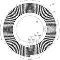
叠层31是致动器30的主体。如图10中所示,叠层31包括细长电极片32和细长电极片33。电极片32和33螺旋地缠绕在用作支撑件的卷簧22的圆周面周围,使得每个电极片32和33在纵向方向上的一端位于内圆周侧上,在纵向方向上的另一端位于外圆周侧上。
电极片32包括在圆周方向上可非轴向拉伸并且具有弹性的弹性体层(介电层)32a和设置在弹性体层32a的一个表面上并且具有弹性的电极32b。弹性体层32a和电极32b均具有细长的矩形形状。电极32b设置在弹性体层32a的一个表面上使得弹性体层32a的纵向方向对应于电极32b的纵向方向。The
电极片33包括在圆周方向上可非轴向拉伸并且具有弹性的弹性体层(介电层)33a和设置在弹性体层33a的一个表面上并且具有弹性的电极33b。弹性体层33a和电极33b均具有细长矩形形状。电极33b设置在弹性体层33a的一个表面上使得弹性体层33a的纵向方向对应于电极33b的纵向方向。The
电极片32和33在电极片32和33的纵向方向上螺旋地缠绕使得电极片32的侧面与电极片33的相应侧面重叠。弹性体层32a或弹性体层33a夹设在缠绕的电极32b和33b之间。具体地,电极片32和33在电极片32和33的纵向方向上缠绕,使得电极32b、弹性体层32a、电极33b和弹性体层33a从叠层31的中心到外圆周以该顺序重复。The
除了上述点之外,弹性体层32a和弹性体层33a与第一实施方式中的弹性体层11b相同。此外,除了上述点之外,电极32b和33b与第一实施方式中的电极11a相同。Except for the above points, the
【致动器的操作】【Operation of Actuator】
接下来,将要描述根据本技术的第六实施方式的致动器30的示例性操作。Next, an exemplary operation of the
当在彼此面对且之间具有弹性体层32a或弹性体层33a的电极32b和33b上施加驱动电压时,由于库仑力而在电极32b与33b之间产生吸引力。因此,在厚度方向上对设置在电极32b与33b之间的弹性体层32a或33a进行施压以便于使其变薄。在高度方向(驱动方向)上将叠层31拉长。When a driving voltage is applied to the
另一方面,当将在彼此面对且之间具有弹性体层32a或弹性体层33a的电极32b和33b上施加驱动电压释放时,在电极32b和33b之间不会产生由于库仑力导致的吸引力。因此,由于弹性体层32a和33a的回弹,弹性体层32a和33a恢复到它们的原始厚度并且收缩到它们的原始尺寸。On the other hand, when the application of the drive voltage to the
【制造致动器的方法】【Method of Manufacturing Actuator】
接下来,将要描述制造根据本技术的第六实施方式的致动器的示例性方法。Next, an exemplary method of manufacturing the actuator according to the sixth embodiment of the present technology will be described.
(生产电极片的步骤)(Procedures of producing electrode sheets)
电极片32是以以下方式生产的。首先,提供基板,并且根据需要对基板的一个表面进行剥离处理。基板可以是无机基板或可以是塑料基板。此外,基板可以是板状基板或可以是片状基板。The
接下来,将用于形成弹性体层的涂层材料涂覆到基板的一个表面以形成具有细长矩形形状的涂层薄膜。这里,涂覆包括印刷。随后,将成型在基板的一个表面上的涂层薄膜进行干燥。干燥条件并无限制,可以是自然干燥或加热干燥。因此,将弹性体层32a成型在基板的一个表面上。接下来,根据需要可以对弹性体层32a的一个表面进行附着力改进处理。Next, the coating material for forming the elastomer layer was applied to one surface of the substrate to form a coating film having an elongated rectangular shape. Here, coating includes printing. Subsequently, the coating film formed on one surface of the substrate is dried. The drying conditions are not limited, and may be natural drying or heating drying. Thus, the
接下来,将导电涂层材料涂覆到弹性体层32a的一个表面以形成具有细长矩形形状的涂层薄膜。随后,对成型在弹性体层32a的一个表面上的涂层薄膜进行干燥以形成电极32b。干燥条件并无限制,可以是自然干燥或加热干燥。因此生产出电极片32。Next, a conductive coating material is applied to one surface of the
以与电极片32的生产方法相同的方法生产电极片33。The
(堆叠电极片的步骤)(Steps for Stacking Electrode Sheets)
通过将电极片32放置在电极片33上使得电极片32的侧面与电极片33的相应侧面重叠并且电极33b面对弹性体层32a来获得具有细长矩形形状的叠层31。
(缠绕叠层的步骤)(Steps for Winding Laminates)
在对获得的叠层31在纵向方向(圆周方向)上非轴向拉伸时,叠层31螺旋缠绕在卷簧22的圆周面周围,使得叠层31在纵向方向上的一端位于内圆周侧上,叠层31的另一端位于外圆周侧上。When the obtained
(密封步骤)(sealing step)
首先,将密封构件23和24装配到叠层31的两端处的相应开口,以将叠层31的两端处的开口封闭。接下来,由密封构件23和24或者卷簧22的两端保持叠层31的两端。从而获得图9和10中的致动器30。First, the sealing
【有益效果】【Beneficial effect】
在根据第六实施方式的致动器30中,叠层31在圆周方向(与驱动方向正交的方向)上承受预应变,在高度方向(驱动方向)上不承受预应变。这种配置可以提高介电击穿强度同时保持在驱动方向上的位移符合要求。此外,叠层31的圆周方向上的预应变使得弹性体层32a和弹性体层33a变薄,从而可以降低驱动电压。In the
【修改】【Revise】
(修改1)(modification 1)
叠层31可以在圆周方向和高度方向中的每个方向上承受预应变。在这种情况下,叠层31在圆周方向上的预应变优选地大于叠层31在高度方向上的预应变。更具体地,叠层31的圆周方向上的预应变为50%或更大,优选80%或更大,更优选100%或更大,还更优选120%或更大。叠层31的圆周方向上的预应变的上限优选400%或更小,更优选300%或更小。同时,叠层31的高度方向上的预应变小于50%,优选30%或更小,更优选20%或更小,还更优选10%或更小,仍然更优选5%或更小。The laminate 31 may be pre-strained in each of the circumferential direction and the height direction. In this case, the prestrain of the laminate 31 in the circumferential direction is preferably greater than the prestrain of the laminate 31 in the height direction. More specifically, the prestrain in the circumferential direction of the
(修改2)(Modification 2)
电极片32和33可以具有圆管形状,电极片32和33可以围绕卷簧22同心地彼此堆叠以形成叠层31。The
<7第七实施方式><7 seventh embodiment>
【致动器的结构】【Structure of Actuator】
如图11A中所示,根据本技术的第七实施方式的致动器40包括纤维形卷41、自卷41的一个端部拉出的端子42A和自卷41的另一端部拉出的端子42B。需要注意的是,在第七实施方式中,与第六实施方式中的部件相同的部件由相同的字符表示,并且省略对其的描述。As shown in FIG. 11A , the
卷41在圆周方向上承受预应变,在纵向方向上不承受预应变。这里,卷41的纵向方向对应于致动器40的驱动方向,卷41的圆周方向对应于与致动器40的驱动方向正交的方向。The
卷41是一示例性叠层。除了卷41在中心部没有卷簧22且具有纤维形状之外,卷41与第六实施方式中的叠层31相同。卷41在中心处可以具有或可以没有腔体。
端子42A和42B具有细长形状。如图11B中所示,端子42A的一端连接到电极32b,另一端自卷41的一个端部拉出。此外,端子42B的一端连接到电极33b,另一端自卷41的另一端拉出。
【有益效果】【Beneficial effect】
在根据第七实施方式的致动器40中,作为示例性叠层的卷41在圆周方向(与驱动方向正交的方向)上承受预应变,在纵向方向(驱动方向)上不承受预应变。这种配置可以提高介电击穿强度同时保持在驱动方向上的位移符合要求。此外,卷41的圆周方向上的预应变使弹性体层32a和弹性体层33a变薄,从而可以降低驱动电压。In the
【修改】【Revise】
(修改1)(modification 1)
卷41可以在圆周方向和纵向方向中的每个方向上承受预应变。在这种情况下,卷41的圆周方向上的预应变优选大于卷41的纵向方向上的预应变。更具体地,卷41的圆周方向上的预应变和纵向方向上的预应变优选地设置成分别与第六实施方式的修改1中的叠层31的圆周方向上的预应变和纵向方向上的预应变相同的值。The
(修改2)(Modification 2)
电极片32和33可以具有圆管形状,电极片32和33可以彼此堆叠以形成纤维形叠层。The
<8第八实施方式><8 Eighth Embodiment>
【触觉演示装置的结构】【Structure of tactile demonstration device】
参见图12,将要描述将本技术应用于触觉演示装置的示例。触觉演示装置是一示例性驱动装置,并且包括致动器阵列411、电压源412和控制器(未示出)。需要注意的是,在第八实施方式中,与第七实施方式中的部件相同的部件由相同的字符表示,并省略对其的描述。Referring to Fig. 12, an example of applying the present technology to a tactile presentation device will be described. The haptic demonstration device is an exemplary drive device and includes an array of
致动器阵列411是示例性驱动构件并且包括多个纤维形致动器40。致动器40对齐使得每个致动器40具有相同的纵向方向并且相邻致动器40的圆周面彼此面对。端子42A通过电线413A连接到电压源412,而端子42B通过电线413B连接到电压源412。电压源412基于来自于控制器(未示出)的控制信号以预定频率向每个致动器410供应驱动电压。这里,致动器40可以与第七实施方式的修改中的致动器相同。
【触觉演示装置的操作】【Operation of the tactile demonstration device】
参见图13A和13B,将要描述具有上述结构的触觉演示装置的示例性操作。这里,如图13A中所示,将要描述包括在致动器阵列411中的致动器阵列411的两端由相应的支撑件414支撑的情形。Referring to FIGS. 13A and 13B , an exemplary operation of the tactile demonstration device having the above structure will be described. Here, as shown in FIG. 13A , a case where both ends of the
如图13B中所示,向致动器40施加驱动电压使致动器40拉长并弯曲。如图13A中所示,施加到致动器40的驱动电压的释放使致动器40收缩、恢复到原始长度并变直。As shown in FIG. 13B, application of a driving voltage to the
【有益效果】【Beneficial effect】
在根据第八实施方式的触觉演示装置中,致动器阵列411包括多个根据第七实施方式的致动器40。这种配置可以提高触觉演示装置的介电击穿强度并可以降低功率消耗。In the tactile demonstration device according to the eighth embodiment, the
【修改】【Revise】
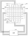
参见图14,将要描述将本技术应用于触觉演示装置的另一个示例。触觉演示装置包括致动器阵列421、电压源412和控制器(未示出)。需要注意的是,在这种修改中,与第八实施方式中的部件相同的部件由相同的字符表示,并省略对其的描述。Referring to FIG. 14, another example of applying the present technology to a tactile presentation device will be described. The haptic demonstration device includes an array of
致动器阵列421包括以栅格样式二维布置的多个致动器40。更具体地,致动器阵列421包括第一致动器组40G1和设置在第一致动器组40G1上的第二致动器组40G2。第一致动器组40G1包括在第一方向上取向的多个致动器40。此外,第二致动器组40G2包括在与第一方向正交的第二方向上取向的多个致动器40。这里,第一方向和第二方向不必要彼此正交。The
<9第九实施方式><9 ninth embodiment>
【机器人的结构】【Structure of robot】
参见图15,将要描述将本技术应用于机器人的示例。机器人包括在臂中的关节驱动装置510。Referring to Fig. 15, an example of applying the present technology to a robot will be described. The robot includes
关节驱动装置510是一示例性驱动装置,包括柱状构件511;一对纤维形致动器512A和512B;支撑件513,其支撑柱状构件511的一端、致动器512A的一端和致动器512B的一端;旋转构件514,其可转动地支撑在柱状构件511的另一端上;以及驱动轴515,其由旋转构件514支撑。The
柱状构件511、致动器512A和512B和支撑件513设置在机器人臂的上臂部中,支撑件513支撑在上臂部的上段中。驱动轴515设置在机器人臂的前臂部中,前臂部在驱动轴515的驱动下移动。旋转构件514设置在机器人臂的上臂部与前臂部之间的关节段中并且起到了关节的作用。The
诸如金属丝之类的线性构件516围绕旋转构件514的圆周面伸展。线性构件516的一端连接到致动器512A的另一端,线性构件516的另一端连接到致动器512B的另一端。旋转构件514因致动器512A和512B通过线性构件而进行的膨胀/收缩而可以转动。A
致动器512A和512B与根据第七实施方式及其修改的致动器40相同。The
机器人还包括电压源(未示出)和控制器(未示出)。电压源通过电线电连接到致动器512A和512B。电压源基于来自于控制器的控制信号向致动器512A和512B供应驱动电压。The robot also includes a voltage source (not shown) and a controller (not shown). The voltage source is electrically connected to actuators 512A and 512B by wires. The voltage source supplies drive voltage to actuators 512A and 512B based on control signals from the controller.
【机器人的操作】【Operation of the robot】
具有上述结构的机器人以如下方式操作。具体地,当控制驱动电压以便于使致动器512A膨胀并对应于致动器512A的膨胀而使致动器512B长度收缩时旋转构件514通过线性构件516在图15中逆时针转动。这样在由箭头517A表示的方向上驱动驱动轴515。另一方面,当控制驱动电压以便于使致动器512A收缩并对应于致动器512A的收缩而使致动器512B长度膨胀时旋转构件514通过线性构件516在图15中顺时针转动。这样在由箭头517B表示的方向上驱动驱动轴515。The robot having the above structure operates in the following manner. Specifically, the
【有益效果】【Beneficial effect】
根据第九实施方式的机器人包括根据第七实施方式或其修改的致动器40作为关节驱动装置510中的致动器512A和512B。这种配置可以提高机器人的耐久性并可以降低功率消耗。The robot according to the ninth embodiment includes the
【修改】【Revise】
第九实施方式阐述了包括在臂中的关节驱动装置510的机器人的结构。然而,机器人可以包括在腿部中的关节驱动装置510。The ninth embodiment explains the structure of a robot including the
示例example
下面将通过示例具体描述本技术,但是本技术并不仅局限于这些示例。The present technology will be specifically described below by way of examples, but the present technology is not limited to these examples.
以下材料用于下面描述的样本1到3。The following materials were used for
聚苯胺:可以从Kakensangyou Corporation获得,甲苯类型(6.0质量%的甲苯溶液)Polyaniline: available from Kakensangyou Corporation, toluene type (6.0 mass% toluene solution)
来自于Kraton聚合物的氢化苯乙烯-丁二烯嵌段共聚物(SEBS),A1535HUHydrogenated Styrene-Butadiene Block Copolymer (SEBS) from Kraton Polymers, A1535HU
马来酸酐接枝的氢化苯乙烯-丁二烯嵌段共聚物:可以从Kraton聚合物获得,FG1924GTMaleic anhydride grafted hydrogenated styrene-butadiene block copolymer: available from Kraton Polymers, FG1924GT
丙烯酸弹性体片:可以从3M Company获得,VHB4905J(初始厚度:500μm)Acrylic elastomer sheet: available from 3M Company, VHB4905J (initial thickness: 500 μm)
硅树脂:可以从Smooth-On,Inc.获得,Dragon Skin 30Silicone: Available from Smooth-On, Inc.,
硅烷偶联剂(3-氨丙基三乙氧基硅烷):可以从Sigma-Aldrich Corporation获得Silane coupling agent (3-aminopropyltriethoxysilane): available from Sigma-Aldrich Corporation
<具有不同拉伸量的样本><Samples with different stretching amounts>
【样本1】【Sample 1】
首先,制备SEBS在甲苯中为50g/L的第一溶液和SEBS-g-MA在甲苯中为50g/L的第二溶液。需要注意的是,因为SEBS-g-MA需要花费很长时间来溶解,所以对SEBS-g-MA和甲苯的混合物在密封状态下超声波搅拌1小时。First, a first solution of 50 g/L of SEBS in toluene and a second solution of 50 g/L of SEBS-g-MA in toluene were prepared. It should be noted that because SEBS-g-MA takes a long time to dissolve, the mixture of SEBS-g-MA and toluene was ultrasonically stirred for 1 hour in a sealed state.
接下来,通过将第一溶液和第二溶液进行混合来制备聚合物溶液,使得第一溶液:第二溶液的质量比率为1:9。随后,制备甲苯中的聚苯胺为6质量%的溶液,该溶液与聚合物溶液进行混合。此时,将聚苯胺相对于整个溶液的量调整为4.2质量%。混合之后,对混合物进行超声波搅拌大约15分钟以提供电极结构的涂层材料。为了将该涂层材料用作介电弹性体致动器(DEA)的电极,优选地添加质量比率为1%或更多的聚苯胺。Next, a polymer solution was prepared by mixing the first solution and the second solution so that the mass ratio of the first solution: the second solution was 1:9. Subsequently, a solution of 6% by mass of polyaniline in toluene was prepared, and this solution was mixed with the polymer solution. At this time, the amount of polyaniline relative to the entire solution was adjusted to 4.2% by mass. After mixing, the mixture was ultrasonically agitated for approximately 15 minutes to provide a coating material for the electrode structure. In order to use the coating material as an electrode of a dielectric elastomer actuator (DEA), it is preferable to add polyaniline at a mass ratio of 1% or more.
接下来,提供没有承受初始应变的矩形丙烯酸弹性体片,通过使用尼伦刷和自然干燥来将电极结构的涂层材料涂覆到丙烯酸弹性体片。从而获得所需的矩形片状叠层。Next, providing a rectangular acrylic elastomer sheet not subjected to initial strain, the coating material of the electrode structure was applied to the acrylic elastomer sheet by using a nylon brush and natural drying. The desired stack of rectangular sheets is thus obtained.
【样本2】【Sample 2】
除了对叠层进行拉伸以使每侧承受50%(拉伸量λ=1.5)的预应变之外,以与样本1相同的方式获得叠层。A laminate was obtained in the same manner as
【样本3】【Sample 3】
除了对叠层进行拉伸以使每侧承受100%(拉伸量λ=2)的预应变之外,以与样本1相同的方式获得叠层。A laminate was obtained in the same manner as
【评估】【Evaluate】
以如下方式评估如上所述而获得的样本1到3的叠层。Laminations of
(叠层的厚度)(layer thickness)
弹性体层的薄膜厚度是从横切的SEM图像获得的。The film thickness of the elastomer layer was obtained from the cross-section SEM images.
(体积电阻率)(volume resistivity)
叠层表面上的电极的体积电阻率是通过根据JIS K 7194-1994的四端子方法确定的。The volume resistivity of the electrodes on the laminate surface was determined by the four-terminal method according to JIS K 7194-1994.
图8示出了样本1到3的叠层的弹性体层的薄膜厚度和体积电阻率的评估结果。因为弹性体是不可压缩材料,所以弹性体层的厚度的减小与双轴拉伸量λ的平方成反比。一致电极的电阻随着拉伸量的增加而增加。如此考虑是因为当拉伸时电极变得更薄。需要注意的是向通过拉伸生产的样本1到3的叠层实际施加驱动电压显示样本1到3的叠层是作为致动器来操作的。FIG. 8 shows the evaluation results of the film thickness and volume resistivity of the laminated elastomer layers of
<在弹性体层与电极之间具有改进的附着力的样本><Sample with improved adhesion between elastomer layer and electrode>
【样本4】【Sample 4】
首先,通过棒式涂覆方法涂覆硅树脂以形成具有50μm厚度的硅弹性体片。接下来,对片的表面进行3分钟的准分子清洗,然后将硅烷偶联剂涂覆到所述片以形成涂层薄膜。随后,将与样本1中相同的电极结构的涂层材料(苯胺/SEBS/SEBS-g-MA混合物)涂覆到涂层薄膜上并进行干燥以形成电极。从而获得所需的叠层。First, a silicone resin was coated by a bar coating method to form a silicone elastomer sheet having a thickness of 50 μm. Next, excimer cleaning was performed on the surface of the sheet for 3 minutes, and then a silane coupling agent was applied to the sheet to form a coating film. Subsequently, the coating material (aniline/SEBS/SEBS-g-MA mixture) of the same electrode structure as in
(带剥离测试)(with peel test)
首先,根据JIS K 5600-5-6:1999对电极进行横切测试。接下来,基于上面在JIS K5600-5-6:1999中描述的1到5的标度评估测试后横切部的状态,基于根据如下标准的评估结果对附着力进行分级。结果,判断附着力为“良好”。First, the electrodes were subjected to a cross-cut test according to JIS K 5600-5-6:1999. Next, the state of the cross-section after the test was evaluated based on the scale of 1 to 5 described above in JIS K5600-5-6:1999, and the adhesion was graded based on the evaluation results according to the following standards. As a result, the adhesion was judged to be "good".
良好:对应于上面提到的JIS K 5600-5-6:1999中描述的状态的0到2的标度Good: A scale of 0 to 2 corresponding to the state described in JIS K 5600-5-6:1999 mentioned above
差:对应于上面提到的JIS K 5600-5-6:1999中描述的状态的3到5的标度Poor: A scale of 3 to 5 corresponding to the state described in JIS K 5600-5-6:1999 mentioned above
需要注意的是,在3到5的标度的情况下,在拉伸时可以将电极剥离。Note that in the case of a scale of 3 to 5, the electrodes can be peeled off when stretched.
上述测试结果显示出弹性体片与电极之间的附着力可以通过利用准分子清洁等对硅胶片的表面预处理之后向硅胶片的表面涂覆硅烷交联剂来提高。需要注意的是通过仅对弹性体片的表面进行准分子清洁或UV清洁液可以提高附着力。The above test results show that the adhesion between the elastomer sheet and the electrode can be improved by applying a silane crosslinking agent to the surface of the silica gel sheet after pretreating the surface of the silica gel sheet by excimer cleaning or the like. Note that adhesion can be improved by applying excimer cleaning or UV cleaning fluid to only the surface of the elastomer sheet.
在上述样本4中,三烷氧基硅烷偶联剂用作硅烷偶联剂。然而,通过使用除了三烷氧基硅烷偶联剂之外的二苯基二甲氧基硅烷偶联剂、单烷氧基硅烷偶联剂等也是可以获得相同的附着力提高效果。此外,根据聚合物的类型可以将丙烯基、甲基丙烯酸基、环氧基、乙烯基、苯乙烯基、异氰酸酯基、巯基用作终端功能基。In the above-mentioned
<具有不同单轴拉伸量和不同双轴拉伸量并且用于刚度和介电击穿强度评估的样本><Samples with different amounts of uniaxial tension and different amounts of biaxial tension for stiffness and dielectric breakdown strength evaluation>
【样本5-1到5-5】【Sample 5-1 to 5-5】
首先,如图16A中所示,提供厚度为93μm的圆形硅弹性体片(弹性体层)611a,并在X和Y轴方向上对弹性体片611a进行双轴拉伸。在这种情况下,正如表1中所示,每个样本的X和Y轴方向上的拉伸比率发生了变化,拉伸量(拉伸比率)调整到1.14、1.43、1.90、2.38和2.86。接下来,如图17A和17B中所示,双轴拉伸后的611a的周边部固定到内径为8cm的环形固定夹具612。随后,如图18A和18B中所示,将含有炭黑粉末的涂层材料涂覆到弹性体片611a的两个表面中的每个表面的中心部,以形成直径为3cm的圆形电极611b。从而获得所需的致动器。First, as shown in FIG. 16A , a circular silicon elastomer sheet (elastomer layer) 611a having a thickness of 93 μm is provided, and the
【样本6-1到6-5】【Samples 6-1 to 6-5】
首先,如图16B中所示,提供厚度为93μm的椭圆形硅弹性体片(弹性体层)611a,并在Y轴方向(短轴方向)上对弹性体片611a进行单轴拉伸。在这种情况下,正如表2中所示,每个样本的Y轴方向上的拉伸比率发生了变化,拉伸量(拉伸比率)调整到1.43、1.90、2.38、2.86和3.81。以与样本5-1到5-5相同的方式实施接下来的步骤。从而获得所需的致动器。First, as shown in FIG. 16B , an elliptical silicon elastomer sheet (elastomer layer) 611a having a thickness of 93 μm is provided, and the
【刚度和介电击穿强度的评估】【Evaluation of stiffness and dielectric breakdown strength】
对如上所述获得的样本5-1到5-5和6-1到6-5的致动器它们的刚度和介电击穿强度进行评估。首先,如图19A和19B中所示,逐渐增大施加给电极611a和611b的电压,在介电击穿之前立即测量电压(下文称作“绝缘强度电压”)V和电极宽度x和y。接下来,基于如下公式从结果中计算介电击穿强度E、X轴方向上的刚度EX和Y轴方向上的刚度EY。The actuators of samples 5-1 to 5-5 and 6-1 to 6-5 obtained as described above were evaluated for their rigidity and dielectric breakdown strength. First, as shown in FIGS. 19A and 19B , the voltage applied to the
介电击穿强度E=(V/t0)×((x×y)/(x0×y0))Dielectric breakdown strength E=(V/t0 )×((x×y)/(x0 ×y0 ))
需要注意的是,在公式中,V:绝缘强度电压,t0:初始厚度,x:X轴方向上的电极宽度,y:Y轴方向上的电极宽度,x0:初始状态下X轴方向上的电极宽度,y0:初始状态下Y轴方向上的电极宽度。这里,初始状态意思是电压施加之前的状态。It should be noted that in the formula, V: dielectric strength voltage, t0 : initial thickness, x: electrode width in the X-axis direction, y: electrode width in the Y-axis direction, x0 : X-axis direction in the initial state The electrode width on , y0 : the electrode width in the Y-axis direction in the initial state. Here, the initial state means a state before voltage application.
X轴方向上的刚度EX=σ/εXStiffness EX in the X-axis direction = σ/εX
Y轴方向上的刚度EY=σ/εYStiffness EY in the direction of the Y axis = σ/εY
需要注意的是,在公式中,σ:麦克斯韦张量;εX:X轴方向上的应变,εY:Y轴方向上的应变,它们从下面的各自的公式中得到:It should be noted that in the formula, σ: Maxwell tensor; εX : the strain in the X-axis direction, εY : the strain in the Y-axis direction, which are obtained from the respective formulas below:
σ=ε×E2(其中ε:介电常数)σ=ε×E2 (where ε: permittivity)
εX=x/x0εX = x/x0
εY=y/y0εY =y/y0
表1示出了样本5-1到5-5的致动器的评估结果。Table 1 shows the evaluation results of the actuators of samples 5-1 to 5-5.
【表1】【Table 1】
表2示出了样本6-1到6-5的致动器的评估结果。Table 2 shows the evaluation results of the actuators of samples 6-1 to 6-5.
【表2】【Table 2】
需要注意的是在表1和2中“介电常数”区域中的表述“AE-B”意思是A×10-B。It is to be noted that the expression "AE-B" in the area of "dielectric constant" in Tables 1 and 2 means A×10-B .
图20A示出了双轴拉伸比率与刚度之间的关系。图20B示出了双轴拉伸比率与介电击穿强度之间的关系。图21A示出了单轴拉伸比率与刚度之间的关系。图21B示出了单轴拉伸比率与介电击穿强度之间的关系。Figure 20A shows the relationship between biaxial stretch ratio and stiffness. Figure 20B shows the relationship between biaxial stretch ratio and dielectric breakdown strength. Figure 21A shows the relationship between uniaxial stretch ratio and stiffness. FIG. 21B shows the relationship between uniaxial stretch ratio and dielectric breakdown strength.
图20A和20B披露了如下事实。具体地,在对弹性体片611a进行X和Y轴方向上的双轴拉伸的情况下,刚度随着双轴拉伸比率的增加而增大。此外,介电击穿强度随着双轴拉伸比率的增加而增大。20A and 20B disclose the following fact. Specifically, in the case where the
图21A和21B披露了如下事实。具体地,在对弹性体片611a进行Y轴方向上的单轴拉伸的情况下,X轴方向上的刚度随着单轴拉伸比率的增加基本恒定。然而,Y轴方向上的刚度随着单轴拉伸比率的增加而增大。此外,介电击穿强度随着单轴拉伸比率的增加而增大。21A and 21B disclose the following fact. Specifically, in the case where the
因此,在与驱动方向垂直的方向上对致动器进行单轴拉伸可以提高介电击穿强度,同时保持驱动方向上的位移符合要求。Therefore, uniaxial stretching of the actuator in the direction perpendicular to the driving direction can improve the dielectric breakdown strength while maintaining the desired displacement in the driving direction.
<包含不同的作为电极材料的碳填料的样本><Samples containing various carbon fillers as electrode materials>
【样本7-1】【Sample 7-1】
首先,如图22A和22B中所示,提供具有15cm×15cm尺寸的正方形弹性体片621a。接下来,如图23A和23B中所示,通过喷射涂覆在弹性体片621a的中心部上成型尺寸为10cm×10cm的矩形电极621b。First, as shown in FIGS. 22A and 22B , a square
将纳米碳和异丙醇以1:20的质量比率(纳米碳:异丙醇)进行混合。将混合物连同直径为10mm的6个氧化锆珠放置在聚丙烯壳体中,50ml容量,(AS ONE Corporation,Aiboy,宽口,PP),并通过摇动震荡10分钟。需要注意的是将可以从Denka Company Limited获得的DENKA BLACK Li(Li-100,平均颗粒尺寸:35nm)用作纳米碳。此外,使用Vortex来摇动。Mix nanocarbons and isopropanol at a mass ratio of 1:20 (nanocarbons:isopropanol). The mixture was placed in a polypropylene housing, 50 ml capacity, (AS ONE Corporation, Aiboy, Wide Mouth, PP) together with 6 zirconia beads with a diameter of 10 mm, and shaken by shaking for 10 minutes. Note that DENKA BLACK Li (Li-100, average particle size: 35 nm) available from Denka Company Limited was used as the nanocarbon. Also, use a Vortex to shake.
(弹性体溶液的制备)(Preparation of Elastomer Solution)
制备甲苯中20质量%(质量比率)弹性体(粘合剂)的溶液。使用硅树脂(可以从DowCorning Toray Co.,Ltd.获得,MS1003)作为弹性体。A solution of 20% by mass (mass ratio) of the elastomer (binder) in toluene was prepared. A silicone resin (available from Dow Corning Toray Co., Ltd., MS1003) was used as the elastic body.
(溶液的制备)(preparation of solution)
首先,将碳填料溶液与弹性体溶液进行混合使得碳填料与弹性体的质量比率(碳填料:弹性体)为10:90,将氧化锆珠添加到混合物中,随后震荡10分钟。接下来,将氧化锆珠移除。从而获得碳硅树脂溶液。First, the carbon filler solution was mixed with the elastomer solution so that the mass ratio of carbon filler to elastomer (carbon filler:elastomer) was 10:90, and zirconia beads were added to the mixture, followed by shaking for 10 minutes. Next, the zirconia beads are removed. Thus a carbosilicone resin solution is obtained.
(涂层电极的生产)(production of coated electrodes)
通过使用可以从Meiji Air Compressor Mfg.Co.,Ltd.获取的空气喷枪(FS110圆形样式)从大约30cm的距离将如上所述获得的碳硅树脂溶液喷射到弹性体片621a,以便于形成在视觉上观察时均匀的涂层。空气流速设定到如下获得的条件:将大约0.15MPa的室内管线连接到空气喷枪;通过1个半转来释放FS110的气体流动控制喷嘴。因此,形成具有大约20μm(峰到峰距离)表面粗糙度和大约10μm厚度的电极621b。从而获得所需的致动器。The carbon silicone resin solution obtained as described above was sprayed onto the
【样本7-2】【Sample 7-2】
除了将可以从Denka Company Limited获取的DENKA BLACK Li(Li-250,平均颗粒尺寸:37nm)用作纳米碳之外,以与样本7-1相同的方式获得致动器。An actuator was obtained in the same manner as in Sample 7-1, except that DENKA BLACK Li (Li-250, average particle size: 37 nm) available from Denka Company Limited was used as nanocarbon.
【样本7-3】【Sample 7-3】
除了将可以从Denka Company Limited获取的DENKA BLACK Li(Li-400,平均颗粒尺寸:48nm)用作纳米碳之外,以与样本7-1相同的方式获得致动器。An actuator was obtained in the same manner as in Sample 7-1, except that DENKA BLACK Li (Li-400, average particle size: 48 nm) available from Denka Company Limited was used as nanocarbon.
【电极传导率的评估】【Evaluation of Electrode Conductivity】
首先,将致动器的端部固定以便于防止膨胀,然后在非拉伸状态(X轴方向上的拉伸比率:1,Y轴方向上的拉伸比率:1)下使四端子探针接触致动器的上表面(电极621b的表面)以测量电阻。接下来,使用轮廓仪测量电极621b的薄膜厚度以确定电极621b的横截面积。然后通过使用如上所述而获得的电极621b的电阻和横截面积来计算电极621b的电阻率。First, fix the end of the actuator so as to prevent expansion, and then make the four-terminal probe The upper surface of the actuator (the surface of the
图24示出了样本7-1到7-3中使用的纳米碳的类型和电阻率之间的关系。图24表示当纳米碳的平均颗粒尺寸为35nm或更大以及37纳米或更小时电极具有极佳的传导率。FIG. 24 shows the relationship between the type of nanocarbon used in Samples 7-1 to 7-3 and the resistivity. FIG. 24 shows that the electrode has excellent conductivity when the average particle size of the nanocarbon is 35 nm or more and 37 nm or less.
<具有不同单轴拉伸量和不同双轴拉伸量并被进行电阻率评估的样本><Samples with different uniaxial stretching amounts and different biaxial stretching amounts and evaluated for resistivity>
除了在制备溶液的步骤中,碳填料溶液和弹性体溶液被混合成碳填料(可以从Denka Company Limited获取,DENKA BLACK Li(Li-100))与弹性体(可以从Dow CorningToray Co.,Ltd.获取,MS1003)的质量比率为19:81、24:76、30:70和35:65之外,以与样本7-1相同的方式获得致动器。Except in the step of preparing the solution, the carbon filler solution and the elastomer solution were mixed into a carbon filler (available from Denka Company Limited, DENKA BLACK Li (Li-100)) and an elastomer (available from Dow Corning Toray Co., Ltd. Acquisition, MS1003) except that the mass ratios were 19:81, 24:76, 30:70, and 35:65, the actuator was obtained in the same manner as in Sample 7-1.
【双轴拉伸中传导率的评估】【Evaluation of Conductivity in Biaxial Tension】
首先,通过将双面胶丙烯酸弹性体片(可以从3M获取,VHB4905J)切割成中空矩形形状来制备一对弹性体片622。随后,如图25A和25B中所示,将上面没有成型有电极621b的弹性体片621a的一部分夹在该对弹性体片622之间以形成要被固定到夹具的部分。接下来,如图26A和26B中所示,将弹性体片622的四条边固定到双轴拉伸夹具623,如图27A和27B中所示,然后对弹性体片622进行双轴拉伸(X轴方向上的拉伸比率:1到3.25,Y轴方向上的拉伸比率:1到3.25)。First, a pair of
接下来,提供装备有根据JIS K 7194标准的四端子探针624的数字万用表(可以从Keithley Instruments获取的2800数字万用表),如图28A和28B中所示,使四端子探针624与拉伸状态中的致动器的上表面(电极621b的表面)接触以测量电阻。接下来,利用轮廓仪测量电极621b的薄膜厚度以确定电极621b的横截面积。然后通过使用如上所述而获得的电极621b的电阻和横截面积来计算电极621b的电阻率。需要注意的是以拉伸比率每0.25倍增量来计算电阻率。Next, a digital multimeter (2800 digital multimeter available from Keithley Instruments) equipped with a four-
【单轴拉伸传导率的评估】【Evaluation of Uniaxial Tensile Conductivity】
拉伸是单轴拉伸并且拉伸比率在1到3.25的范围内之外,以与上面所述的双轴拉伸中的传导率评估相同的方式测量电阻率。Stretching was uniaxial stretching and the stretching ratio was outside the range of 1 to 3.25, and resistivity was measured in the same manner as the conductivity evaluation in biaxial stretching described above.
表3示出了样本8-1到8-4的致动器的评估结果。Table 3 shows the evaluation results of the actuators of Samples 8-1 to 8-4.
【表3】【table 3】

图29A示出了拉伸比率与电阻率之间的关系。图29B示出了由拉伸造成的面积变化与电阻率之间的关系。图29A和29B表示与拉伸对应的电阻变化不取决于一个轴向方向上的拉伸大小,而是取决于整个片的面积变化。Fig. 29A shows the relationship between stretch ratio and resistivity. FIG. 29B shows the relationship between area change due to stretching and resistivity. Figures 29A and 29B show that the change in resistance corresponding to stretching does not depend on the magnitude of stretching in one axial direction, but on the change in area across the sheet.
<其中弹性体层和电极堆叠的致动器><Actuator in which an elastomer layer and an electrode are stacked>
在下面所述的样本9-1到9-3和10-1到10-3中,与样本5-1中的部件对应的部件由相同的字符表示。In samples 9-1 to 9-3 and 10-1 to 10-3 described below, parts corresponding to those in sample 5-1 are indicated by the same characters.
【样本9-1到9-3】【Samples 9-1 to 9-3】
电极611b和厚度为100μm的硅弹性体片611a交替地彼此堆叠以形成叠层。此外,如表4中所示,X轴方向和Y轴方向上的双轴拉伸比率设定到1、1.5和1.7。需要注意的是,在堆叠中,弹性体片611a夹在电极611b之间,弹性体片611a的数量是10。此外,生产电极611b以包含纳米碳(可以从Denka Company Limited获取,DEKA BLACK Li(Li-100))和弹性体(可以从Dow Corning Toray Co.Ltd.获取,MS1003),且质量比率(纳米碳:硅弹性体)为19:81。除了上述点之外,以与样本5-1相同的方式获得致动器。
【样本10-1到10-3】【Samples 10-1 to 10-3】
除了弹性体片的数量为1之外,以与样本9-1到9-3相同的方式获得致动器。Actuators were obtained in the same manner as Samples 9-1 to 9-3 except that the number of elastic body pieces was one.
【介电击穿强度的评估】【Evaluation of Dielectric Breakdown Strength】
以与样本5-1的介电击穿强度的评估相同的方式计算如上所述获得的样本9-1到9-3和10-1到10-3的致动器的介电击穿强度。The dielectric breakdown strengths of the actuators of the samples 9-1 to 9-3 and 10-1 to 10-3 obtained as described above were calculated in the same manner as the evaluation of the dielectric breakdown strength of the sample 5-1.
表4示出了样本9-1到9-3的致动器的评估结果Table 4 shows the evaluation results of the actuators of samples 9-1 to 9-3
【表4】【Table 4】

表5示出了样本10-1到10-3的致动器的评估结果。Table 5 shows the evaluation results of the actuators of Samples 10-1 to 10-3.
【表5】【table 5】

图30A示出了双轴拉伸比率与介电击穿强度之间的关系。图30A表示包括10个堆叠的弹性体片611a的致动器的介电击穿强度如包括单个弹性体片611a的致动器的介电击穿强度一样随着拉伸量的增加而增大。Figure 30A shows the relationship between biaxial stretch ratio and dielectric breakdown strength. Figure 30A shows that the dielectric breakdown strength of the actuator comprising 10 stacked
【面积变化的评估】【Evaluation of area change】
获得了施加100MV/m电场之后样本9-2和9-3(包括10个堆叠的弹性体片611a的拉伸样本)的面积变化。Changes in area of samples 9-2 and 9-3 (tensile samples including 10 stacked
表6示出了样本9-2和9-3的致动器的评估结果。Table 6 shows the evaluation results of the actuators of Samples 9-2 and 9-3.
【表6】【Table 6】

图30B示出了双轴拉伸比率与面积变化之间的关系。图30B表示包括10个堆叠的弹性体片611a的拉伸的致动器可以获得10%或更大的面积变化。FIG. 30B shows the relationship between the biaxial stretching ratio and the change in area. Figure 30B shows that stretched actuators comprising 10 stacked
上面已经具体描述了本技术的示例的实施方式。然而,本技术并不局限于上述实施方式和示例。在不脱离本技术的技术精髓的前提下可以对本技术做出各种修改。The exemplary embodiments of the present technology have been specifically described above. However, the present technology is not limited to the above-mentioned embodiments and examples. Various modifications can be made to the present technology without departing from the technical essence of the present technology.
例如,上述实施方式和示例中提到的配置、方法、工艺、形状、材料、数值等仅是示例。必要时可以使用不同的配置、方法、工艺、形状、材料、数值等。For example, the configurations, methods, processes, shapes, materials, numerical values, etc. mentioned in the above embodiments and examples are just examples. Different configurations, methods, processes, shapes, materials, numerical values, etc. may be used as necessary.
此外,上述实施方式和示例中的配置、方法、工艺、形状、材料、数值等可以在不脱离本技术的精髓的前提下进行组合。In addition, configurations, methods, processes, shapes, materials, numerical values, and the like in the above-described embodiments and examples may be combined without departing from the spirit of the present technology.
此外,本技术还配置如下。In addition, the present technology is also configured as follows.
(1)一种致动器,包括:(1) An actuator comprising:
叠层,包括:Laminates, including:
弹性体层;以及an elastomeric layer; and
设置在弹性体层每个表面上的弹性电极,elastic electrodes disposed on each surface of the elastomeric layer,
其中叠层至少在一个方向上承受50%或更大的预应变。Wherein the laminate bears a pre-strain of 50% or more in at least one direction.
(2)根据(1)所述的致动器,其中(2) The actuator according to (1), wherein
弹性体层具有10MPa或更小的杨氏模量,The elastomer layer has a Young's modulus of 10 MPa or less,
弹性体层具有200%或更大的断裂应变。The elastomeric layer has a strain at break of 200% or greater.
(3)根据(1)或(2)所述的致动器,其中(3) The actuator according to (1) or (2), wherein
预应变释放状态中的电极具有500μm或更小的平均厚度,The electrode in the pre-strain released state has an average thickness of 500 μm or less,
在叠层承受100%或更大的应变的情况下电极具有10MΩ·cm或更小的体积电阻率。The electrode has a volume resistivity of 10 MΩ·cm or less in the case where the laminate is subjected to a strain of 100% or more.
(4)根据(1)到(3)中任一项所述的致动器,其中电极包含导电填料或导电聚合物中的至少一种。(4) The actuator according to any one of (1) to (3), wherein the electrode contains at least one of a conductive filler or a conductive polymer.
(5)根据(4)所述的致动器,其中电极还包含弹性体。(5) The actuator according to (4), wherein the electrode further includes an elastic body.
(6)根据(4)或(5)所述的致动器,其中导电填料包含碳基填料、金属基填料、金属氧化物基填料或者金属涂层填料中的至少一种。(6) The actuator according to (4) or (5), wherein the conductive filler contains at least one of a carbon-based filler, a metal-based filler, a metal oxide-based filler, or a metal-coated filler.
(7)根据(1)到(3)中任一项所述的致动器,其中(7) The actuator according to any one of (1) to (3), wherein
电极包含导电填料,The electrodes contain conductive fillers,
导电填料承载在弹性体层的表面上。The conductive filler is carried on the surface of the elastomeric layer.
(8)根据(1)到(7)中任一项所述的致动器,其中电极是固体、胶体或液体。(8) The actuator according to any one of (1) to (7), wherein the electrodes are solid, colloid or liquid.
(9)根据(1)到(3)中任一项所述的致动器,其中电极包含弹性离子导电材料和电解质。(9) The actuator according to any one of (1) to (3), wherein the electrode contains an elastic ion-conductive material and an electrolyte.
(10)根据(1)到(3)中任一项所述的致动器,其中电极包含悬胶以及导电填料或导电聚合物中的至少一种。(10) The actuator according to any one of (1) to (3), wherein the electrode contains a gel suspension and at least one of a conductive filler or a conductive polymer.
(11)根据(1)到(10)中任一项所述的致动器,其中电极和弹性体层交替地重复堆叠。(11) The actuator according to any one of (1) to (10), wherein the electrodes and the elastic body layers are alternately repeatedly stacked.
(12)根据(1)到(11)中任一项所述的致动器,其中电极的一部分具有超过10MPa的杨氏模量。(12) The actuator according to any one of (1) to (11), wherein a part of the electrode has a Young's modulus exceeding 10 MPa.
(13)根据(1)到(12)中任一项所述的致动器,其中对弹性体层与电极之间的界面进行附着力改进处理。(13) The actuator according to any one of (1) to (12), wherein the interface between the elastic body layer and the electrode is subjected to an adhesion improving treatment.
(14)根据(1)到(13)中任一项所述的致动器,还包括保持叠层的保持单元,(14) The actuator according to any one of (1) to (13), further comprising a holding unit holding the stack,
其中该保持单元能够改变叠层的尺寸。Wherein the holding unit is capable of changing the size of the stack.
(15)根据(1)到(13)中任一项所述的致动器,还包括将叠层保持在预应变状态的保持单元。(15) The actuator according to any one of (1) to (13), further including a holding unit that holds the laminate in a pre-strained state.
(16)根据(1)到(15)中任一项所述的致动器,其中(16) The actuator according to any one of (1) to (15), wherein
叠层在与驱动方向正交的方向上承受50%或更大的预应变,The laminate is pre-strained by 50% or more in the direction normal to the drive direction,
与驱动方向正交的方向上的预应变大于驱动方向上的预应变。The prestrain in the direction orthogonal to the driving direction is greater than the prestrain in the driving direction.
(17)根据(1)到(15)中任一项所述的致动器,其中(17) The actuator according to any one of (1) to (15), wherein
叠层在与驱动方向正交的方向上承受50%或更大的预应变,在驱动方向上不承受预应变。The laminate is pre-strained by 50% or more in the direction normal to the drive direction and not pre-strained in the drive direction.
(18)根据(1)到(17)中任一项所述的致动器,其中电极包含碳基填料和硅树脂。(18) The actuator according to any one of (1) to (17), wherein the electrode contains a carbon-based filler and a silicone resin.
(19)根据(1)到(18)中任一项所述的致动器,其中叠层具有圆管形状或纤维形状。(19) The actuator according to any one of (1) to (18), wherein the laminate has a circular tube shape or a fiber shape.
(20)一种致动器,包括(20) An actuator comprising
叠层,包括:Laminates, including:
弹性体层;elastomer layer;
设置在弹性体层每个表面上的弹性电极,elastic electrodes disposed on each surface of the elastomeric layer,
其中叠层至少在一个方向上承受预应变,弹性体层具有3μm或更小的平均厚度。Where the laminate is pre-strained in at least one direction, the elastomeric layer has an average thickness of 3 μm or less.
(21)一种制造致动器的方法,该方法包括:(21) A method of manufacturing an actuator, the method comprising:
将电极和弹性体层交替堆叠以形成叠层;以及alternately stacking the electrode and elastomer layers to form a laminate; and
至少在一个方向上对形成的叠层进行拉伸。The resulting laminate is stretched in at least one direction.
(22)根据(21)所述的制造致动器的方法,其中叠层的形成包括:(22) The method of manufacturing an actuator according to (21), wherein forming the laminate includes:
将电极和弹性体层交替地堆叠在基板上以形成分层产品;Alternately stacking electrode and elastomer layers on a substrate to form a layered product;
从基板上部分地或整体地剥落形成的分层产品以形成叠层。The formed layered product is partially or entirely exfoliated from the substrate to form a laminate.
(23)根据(21)或(22)所述的制造致动器的方法,其中(23) The method of manufacturing an actuator according to (21) or (22), wherein
通过涂覆和干燥包含导电材料的涂层材料来形成电极,The electrodes are formed by applying and drying a coating material containing a conductive material,
通过涂覆和干燥包含弹性体的涂层材料来形成弹性体层。The elastomer layer is formed by applying and drying an elastomer-containing coating material.
(24)根据(21)或(22)所述的制造致动器的方法,其中通过涂覆和干燥包含碳基填料、硅树脂和非极性溶剂的涂层材料形成电极。(24) The method of manufacturing an actuator according to (21) or (22), wherein the electrodes are formed by coating and drying a coating material containing a carbon-based filler, a silicone resin, and a nonpolar solvent.
参考标记列表List of Reference Marks
10、20、30、40、111、210、312 致动器10, 20, 30, 40, 111, 210, 312 actuators
11、21、31 叠层11, 21, 31 stacks
11a、21a 电极11a, 21a electrodes
21a、21b 弹性体层21a, 21b Elastomer layer
12、112、212 保持单元12, 112, 212 holding unit
22 卷簧22 coil spring
23、24 密封单元23, 24 sealed unit
32、33 电极片32, 33 electrode sheet
32a、33a 弹性体层32a, 33a Elastomer layer
32b、33b 电极32b, 33b electrodes
40G1 第一致动器组40G1 first actuator group
40G2 第二致动器组40G2 second actuator group
41 卷41 rolls
42A、42B 端子42A, 42B terminals
110 扬声器110 speakers
212a 轴212a shaft
212b,212c 保持构件212b, 212c retaining member
310 内窥镜310 Endoscopes
311 操作部311 Operation Department
313 远端部313 distal end
321 控制器321 controller
322 弯曲驱动电路322 bending drive circuit
323 电源323 power supply
411、421 致动器阵列411, 421 actuator array
412 电压源412 Voltage source
413A、413B 电线413A, 413B wire
414 支撑件414 Supports
510 关节驱动装置510 joint drive
511 柱状构件511 columnar member
512A,、512B 致动器512A, 512B Actuator
513 支撑件513 Supports
514 旋转构件514 rotating member
515 驱动轴515 drive shaft
516 线性构件516 Linear components
611a、621a、622 弹性体片611a, 621a, 622 Elastomer sheets
611b、621b 电极611b, 621b electrodes
612 固定夹具612 Fixtures
623 双轴拉伸夹具623 Biaxial Tensile Grip
624 四端子探针624 Four Terminal Probes
Claims (22)
Translated fromChineseApplications Claiming Priority (3)
| Application Number | Priority Date | Filing Date | Title |
|---|---|---|---|
| JP2016-257445 | 2016-12-29 | ||
| JP2016257445 | 2016-12-29 | ||
| PCT/JP2017/047412WO2018124308A1 (en) | 2016-12-29 | 2017-12-29 | Actuator and manufacturing method therefor |
Publications (2)
| Publication Number | Publication Date |
|---|---|
| CN110100384A CN110100384A (en) | 2019-08-06 |
| CN110100384Btrue CN110100384B (en) | 2022-11-01 |
Family
ID=62709481
Family Applications (1)
| Application Number | Title | Priority Date | Filing Date |
|---|---|---|---|
| CN201780079636.1AActiveCN110100384B (en) | 2016-12-29 | 2017-12-29 | Actuator and method of manufacturing the same |
Country Status (5)
| Country | Link |
|---|---|
| US (1) | US11444555B2 (en) |
| EP (1) | EP3565103B1 (en) |
| JP (1) | JP7626525B2 (en) |
| CN (1) | CN110100384B (en) |
| WO (1) | WO2018124308A1 (en) |
Families Citing this family (19)
| Publication number | Priority date | Publication date | Assignee | Title |
|---|---|---|---|---|
| JP7089979B2 (en)* | 2018-08-07 | 2022-06-23 | 株式会社フコク | Actuator |
| WO2020090561A1 (en)* | 2018-10-31 | 2020-05-07 | 正毅 千葉 | Manufacturing method of dielectric elastomer transducer, and dielectric elastomer transducer |
| US10859101B2 (en)* | 2018-12-10 | 2020-12-08 | Toyota Motor Engineering & Manufacturing North America, Inc. | Soft-bodied actuator with pinched configuration |
| CN109571458B (en)* | 2019-01-08 | 2023-09-22 | 中国地质大学(武汉) | Carbon nanocomposite working medium driver |
| CN110172126B (en)* | 2019-03-13 | 2020-09-01 | 浙江大学 | Artificial muscle driving module based on double-network hydrogel and dielectric elastomer and preparation method thereof |
| JP2022126892A (en)* | 2019-07-12 | 2022-08-31 | パナソニックIpマネジメント株式会社 | robot |
| CN110524532B (en)* | 2019-08-31 | 2020-12-11 | 三体次元信息科技(宁波)有限公司 | Electronic artificial muscle electric actuator, preparation method thereof and application thereof in finger driving device |
| WO2021070809A1 (en)* | 2019-10-08 | 2021-04-15 | ソニー株式会社 | Actuator, method of manufacturing same, driving device, and electronic equipment |
| CN111129283A (en)* | 2019-12-27 | 2020-05-08 | 中国科学院宁波材料技术与工程研究所 | Driving device, dielectric elastomer actuator and manufacturing method thereof |
| CN111081862B (en)* | 2019-12-31 | 2022-01-18 | 清华大学 | Dielectric effect-based electrostrictive device and manufacturing method thereof |
| US20220125454A1 (en)* | 2020-10-23 | 2022-04-28 | Vicora, Inc. | Actuated thrombectomy device |
| US20240128896A1 (en)* | 2021-02-09 | 2024-04-18 | Sony Group Corporation | Actuator and electronic equipment |
| CN113199844B (en)* | 2021-05-11 | 2022-12-16 | 浙江大学 | Anisotropic dielectric elastomer fiber driver and preparation method thereof |
| CN113427494A (en)* | 2021-07-02 | 2021-09-24 | 西安工业大学 | Bionic water snake-shaped robot based on dielectric elastomer |
| CN114147699B (en)* | 2021-12-10 | 2023-05-23 | 上海交通大学 | Pneumatic soft linear driver based on triple-period minimum curved surface |
| GB2624655A (en)* | 2022-11-24 | 2024-05-29 | Rolls Royce Plc | Actuators |
| CN115890643B (en)* | 2022-12-15 | 2023-09-05 | 之江实验室 | Electric-driven artificial muscle fiber with bidirectional linear strain and preparation method thereof |
| GB2629994A (en) | 2022-12-15 | 2024-11-13 | Zhejiang Lab | Electric-driven artificial muscle fiber having bidirectional linear strain and preparation method therefor |
| CN120547483B (en)* | 2025-07-31 | 2025-09-26 | 瑞声光电科技(常州)有限公司 | Conductive diaphragm and preparation method thereof, and loudspeaker |
Citations (8)
| Publication number | Priority date | Publication date | Assignee | Title |
|---|---|---|---|---|
| JP2001238472A (en)* | 2001-01-29 | 2001-08-31 | Hitachi Ltd | Ultrasonic motor |
| JP2003505865A (en)* | 1999-07-20 | 2003-02-12 | エスアールアイ インターナショナル | Improved electroactive polymer |
| CN1435899A (en)* | 2002-01-31 | 2003-08-13 | 丰田自动车株式会社 | Laminated piezoelectric actuator |
| CN1504999A (en)* | 2002-11-28 | 2004-06-16 | Tdk��ʽ���� | Actuator and method of making the same |
| JP2008187881A (en)* | 2007-01-31 | 2008-08-14 | Seiko Epson Corp | Actuator, actuator manufacturing method, optical scanner, and image forming apparatus |
| JP2012065426A (en)* | 2010-09-15 | 2012-03-29 | Toyoda Gosei Co Ltd | Manufacturing method of actuator |
| JP2016509826A (en)* | 2013-01-16 | 2016-03-31 | バイエル・マテリアルサイエンス・アクチェンゲゼルシャフトBayer MaterialScience AG | Method for manufacturing a multilayer electromechanical transducer |
| JP2016201995A (en)* | 2016-08-09 | 2016-12-01 | バンドー化学株式会社 | Flexible sheet for transducer |
Family Cites Families (13)
| Publication number | Priority date | Publication date | Assignee | Title |
|---|---|---|---|---|
| US6586859B2 (en)* | 2000-04-05 | 2003-07-01 | Sri International | Electroactive polymer animated devices |
| US6812624B1 (en)* | 1999-07-20 | 2004-11-02 | Sri International | Electroactive polymers |
| US6891317B2 (en)* | 2001-05-22 | 2005-05-10 | Sri International | Rolled electroactive polymers |
| DK2264801T3 (en) | 1999-07-20 | 2013-01-07 | Stanford Res Inst Int | Electroactive Polymers |
| JP2005312230A (en) | 2004-04-23 | 2005-11-04 | Konica Minolta Holdings Inc | Roll electromechanical conversion element |
| KR20090007710A (en)* | 2006-03-17 | 2009-01-20 | 산요덴키가부시키가이샤 | Nonaqueous Electrolyte Battery and Manufacturing Method Thereof |
| US8354774B2 (en)* | 2007-08-17 | 2013-01-15 | Kuraray Co., Ltd. | Dielectric material for polymeric actuator, and polymeric actuator using the same |
| US7719164B2 (en)* | 2008-08-06 | 2010-05-18 | Honeywell International Inc. | Patterned dielectric elastomer actuator and method of fabricating the same |
| JP2014507930A (en)* | 2011-03-09 | 2014-03-27 | バイエル・インテレクチュアル・プロパティ・ゲゼルシャフト・ミット・ベシュレンクテル・ハフツング | Electroactive polymer energy converter |
| US8941392B1 (en)* | 2013-08-17 | 2015-01-27 | Bend Labs, Inc. | Angular displacement sensor of compliant material |
| EP3304609A1 (en)* | 2015-05-29 | 2018-04-11 | Covestro Deutschland AG | An electromechanical converter consisting of a cyclically stable, reversible, and expandable electrode, and a method for producing same |
| US10110981B2 (en)* | 2015-06-30 | 2018-10-23 | W. L. Gore & Associates, Inc. | Vibro acoustic cover using expanded PTFE composite |
| JP6904356B2 (en)* | 2016-08-08 | 2021-07-14 | ソニーグループ株式会社 | Actuators, actuator modules, endoscopes, endoscope modules and control methods |
- 2017
- 2017-12-29USUS16/472,458patent/US11444555B2/enactiveActive
- 2017-12-29EPEP17886114.2Apatent/EP3565103B1/enactiveActive
- 2017-12-29WOPCT/JP2017/047412patent/WO2018124308A1/ennot_activeCeased
- 2017-12-29JPJP2018559653Apatent/JP7626525B2/enactiveActive
- 2017-12-29CNCN201780079636.1Apatent/CN110100384B/enactiveActive
Patent Citations (8)
| Publication number | Priority date | Publication date | Assignee | Title |
|---|---|---|---|---|
| JP2003505865A (en)* | 1999-07-20 | 2003-02-12 | エスアールアイ インターナショナル | Improved electroactive polymer |
| JP2001238472A (en)* | 2001-01-29 | 2001-08-31 | Hitachi Ltd | Ultrasonic motor |
| CN1435899A (en)* | 2002-01-31 | 2003-08-13 | 丰田自动车株式会社 | Laminated piezoelectric actuator |
| CN1504999A (en)* | 2002-11-28 | 2004-06-16 | Tdk��ʽ���� | Actuator and method of making the same |
| JP2008187881A (en)* | 2007-01-31 | 2008-08-14 | Seiko Epson Corp | Actuator, actuator manufacturing method, optical scanner, and image forming apparatus |
| JP2012065426A (en)* | 2010-09-15 | 2012-03-29 | Toyoda Gosei Co Ltd | Manufacturing method of actuator |
| JP2016509826A (en)* | 2013-01-16 | 2016-03-31 | バイエル・マテリアルサイエンス・アクチェンゲゼルシャフトBayer MaterialScience AG | Method for manufacturing a multilayer electromechanical transducer |
| JP2016201995A (en)* | 2016-08-09 | 2016-12-01 | バンドー化学株式会社 | Flexible sheet for transducer |
Also Published As
| Publication number | Publication date |
|---|---|
| JPWO2018124308A1 (en) | 2019-11-07 |
| US20200161989A1 (en) | 2020-05-21 |
| WO2018124308A1 (en) | 2018-07-05 |
| CN110100384A (en) | 2019-08-06 |
| JP7626525B2 (en) | 2025-02-04 |
| EP3565103B1 (en) | 2025-03-12 |
| EP3565103A4 (en) | 2020-02-26 |
| EP3565103A1 (en) | 2019-11-06 |
| US11444555B2 (en) | 2022-09-13 |
Similar Documents
| Publication | Publication Date | Title |
|---|---|---|
| CN110100384B (en) | Actuator and method of manufacturing the same | |
| Choi et al. | Stretchable, transparent, and stretch-unresponsive capacitive touch sensor array with selectively patterned silver nanowires/reduced graphene oxide electrodes | |
| JP5711124B2 (en) | Flexible conductive materials and transducers | |
| WO2012050128A1 (en) | Flexible conductive material and transducer, flexible circuit board, and electromagnetic shield using said flexible conductive material | |
| WO2014098017A1 (en) | Conductive material and transducer using same | |
| CN103563012A (en) | Dielectric film and converter using it | |
| US11433425B2 (en) | Actuator, driving member, tactile sense presenting device, and driving device | |
| WO2013022030A1 (en) | Flexible conductive material | |
| TWI684999B (en) | Conductive film | |
| US20140202744A1 (en) | Conductive composition and conductive film | |
| Hubertus et al. | Nanoscale nickel-based thin films as highly conductive electrodes for dielectric elastomer applications with extremely high stretchability up to 200% | |
| Tugui et al. | Stretchable energy harvesting devices: attempts to produce high-performance electrodes | |
| WO2015083421A1 (en) | Conductive material and transducer using same | |
| WO2015029656A1 (en) | Flexible conductive material and transducer | |
| CN103444069B (en) | converter | |
| JP6067447B2 (en) | Conductive materials and transducers | |
| Suresh et al. | The role of chemical microstructures and compositions on the actuation performance of dielectric elastomers: A materials research perspective | |
| JP6022281B2 (en) | Transducer | |
| WO2016031137A1 (en) | Transducer and electronic device | |
| JP5646259B2 (en) | Method for producing elastomeric material | |
| JP2013147669A (en) | Electrically conductive material | |
| US20220402245A1 (en) | Actuator, method for manufacturing same, drive device, and electronic device | |
| KR20110087713A (en) | Flexible transparent electrode and polymer actuator using the same | |
| Zhang et al. | Hollow fiber-based strain sensors with desirable modulus and sensitivity at effective deformation for dexterous electroelastomer cylindrical actuator | |
| Ren | Synthesizing A Phase Changing Bistable Electroactive Polymer And Silver Nanoparticles Coated Fabric As A Resistive Heating Element |
Legal Events
| Date | Code | Title | Description |
|---|---|---|---|
| PB01 | Publication | ||
| PB01 | Publication | ||
| SE01 | Entry into force of request for substantive examination | ||
| SE01 | Entry into force of request for substantive examination | ||
| GR01 | Patent grant | ||
| GR01 | Patent grant |