CN110099641B - Staple cartridge and arrangement of staples and staple cavities therein - Google Patents
Staple cartridge and arrangement of staples and staple cavities thereinDownload PDFInfo
- Publication number
- CN110099641B CN110099641BCN201780080004.7ACN201780080004ACN110099641BCN 110099641 BCN110099641 BCN 110099641BCN 201780080004 ACN201780080004 ACN 201780080004ACN 110099641 BCN110099641 BCN 110099641B
- Authority
- CN
- China
- Prior art keywords
- staple
- staples
- patent application
- entitled
- Prior art date
- Legal status (The legal status is an assumption and is not a legal conclusion. Google has not performed a legal analysis and makes no representation as to the accuracy of the status listed.)
- Active
Links
Images


Landscapes
- Surgical Instruments (AREA)
Abstract
Translated fromChinese
Description
Translated fromChinese背景技术Background technique
本发明涉及外科器械,并且在各种布置中,涉及被设计成缝合和切割组织的外科缝合和切割器械及与其一起使用的钉仓。The present invention relates to surgical instruments and, in various arrangements, to surgical stapling and cutting instruments designed to staple and cut tissue and staple cartridges for use therewith.
附图说明Description of drawings
本文所述的实施方案的各种特征连同其优点可结合如下附图根据以下描述来加以理解:The various features of the embodiments described herein, along with their advantages, can be understood from the following description in conjunction with the accompanying drawings:
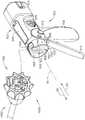
图1是可操作地联接到柄部组件实施方案的可互换外科工具组件实施方案的透视图;1 is a perspective view of an interchangeable surgical tool assembly embodiment operably coupled to a handle assembly embodiment;
图2是图1的柄部组件和可互换外科工具组件的部分的分解组装视图;Figure 2 is an exploded assembled view of portions of the handle assembly and interchangeable surgical tool assembly of Figure 1;
图3是图1和图2所示的可互换外科工具组件实施方案的远侧部分的透视图,其中为清楚起见省略了其多个部分;Fig. 3 is a perspective view of a distal portion of the embodiment of the interchangeable surgical tool assembly shown in Figs. 1 and 2, with portions thereof omitted for clarity;
图4是图1的可互换外科工具组件的远侧部分的分解组装视图;Figure 4 is an exploded assembled view of the distal portion of the interchangeable surgical tool assembly of Figure 1;
图5是其中限定有多个钉腔的钉仓体的透视图;5 is a perspective view of a staple cartridge body with a plurality of staple cavities defined therein;
图6是图5的钉仓的局部透视底视图;Figure 6 is a partial perspective bottom view of the staple cartridge of Figure 5;
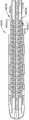
图7是图5的钉仓体的顶部平面图,并且示出了被定位在仓体的纵向狭槽中的切割元件;Fig. 7 is a top plan view of the staple cartridge body of Fig. 5 and showing the cutting element positioned in the longitudinal slot of the cartridge body;
图8是图5的钉仓体的底部平面图,并且示出了被定位在钉腔中的驱动器;8 is a bottom plan view of the staple cartridge body of FIG. 5 and showing the driver positioned in the staple cavity;
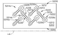
图9是植入在缝合组织中并由图5的钉仓体生成的钉线,并且示出了可能从具有虚线的钉线缺失的某些钉;9 is a staple line implanted in sutured tissue and generated by the staple cartridge body of FIG. 5, and showing some staples that may be missing from the staple line with dashed lines;
图10是图9的钉线中的钉的侧正视图;Figure 10 is a side elevational view of a staple in the staple line of Figure 9;
图11是钉的侧正视图;Figure 11 is a side elevational view of the nail;
图12是具有限定于其中的多个钉腔的钉仓体的底部平面图,并且示出了被定位在钉腔中的驱动器;12 is a bottom plan view of a staple cartridge body having a plurality of staple cavities defined therein and showing a driver positioned within the staple cavities;
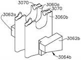
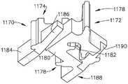
图13是图8的近侧钉腔中的驱动器的透视图;Figure 13 is a perspective view of the driver in the proximal staple cavity of Figure 8;
图14是图13的驱动器的侧正视图,并且示出了具有虚线的偏置斜坡表面;Fig. 14 is a side elevational view of the driver of Fig. 13 and showing the offset ramp surface with dashed lines;
图15是图13的驱动器的平面图;Figure 15 is a plan view of the driver of Figure 13;
图16是图13的驱动器的前正视图;Figure 16 is a front elevational view of the driver of Figure 13;
图17是图12的钉仓体的近侧钉腔中的驱动器的平面图;Figure 17 is a plan view of the driver in the proximal staple cavity of the staple cartridge body of Figure 12;
图18是图17的驱动器的前正视图;Figure 18 is a front elevational view of the driver of Figure 17;
图19是其中限定有多个钉腔的钉仓体的顶部平面图;19 is a top plan view of a staple cartridge body with a plurality of staple cavities defined therein;
图20是图19的钉仓体的底部平面图,并且示出了被定位在钉腔中的驱动器;Figure 20 is a bottom plan view of the staple cartridge body of Figure 19 and showing the driver positioned in the staple cavity;
图21是图20的近侧钉腔中的驱动器的透视图;Figure 21 is a perspective view of the driver in the proximal staple cavity of Figure 20;
图22是图21的驱动器的前正视图;Figure 22 is a front elevational view of the driver of Figure 21;
图23是图21的驱动器的平面图;Figure 23 is a plan view of the driver of Figure 21;
图24是图21的驱动器的侧正视图,并且示出了具有虚线的偏置斜坡表面;Fig. 24 is a side elevational view of the driver of Fig. 21 and showing the offset ramp surface with dashed lines;
图25是其中限定有多个钉腔的钉仓体的顶部平面图;25 is a top plan view of a staple cartridge body with a plurality of staple cavities defined therein;
图26是图25的钉仓体的底部平面图,并且示出了被定位在钉腔中的驱动器;Figure 26 is a bottom plan view of the staple cartridge body of Figure 25 and showing the driver positioned in the staple cavity;
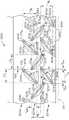
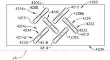
图27是具有限定在其中的多个成角度取向的钉腔的钉仓体的一部分的平面图,并且示出了钉腔中的钉;27 is a plan view of a portion of a staple cartridge body having a plurality of angularly oriented staple cavities defined therein and showing the staples in the staple cavities;
图28是具有限定在其中的多个成角度取向的钉腔的钉仓体的一部分的平面图,并且示出了钉腔中的钉;28 is a plan view of a portion of a staple cartridge body having a plurality of angularly oriented staple cavities defined therein and showing the staples in the staple cavities;
图29是具有限定在其中的多个成角度取向的钉腔的钉仓体的一部分的平面图,并且示出了钉腔中的钉;29 is a plan view of a portion of a staple cartridge body having a plurality of angularly oriented staple cavities defined therein and showing the staples in the staple cavities;
图30是具有限定在其中的多个成角度取向的钉腔的钉仓体的一部分的平面图,并且示出了钉腔中的钉;30 is a plan view of a portion of a staple cartridge body having a plurality of angularly oriented staple cavities defined therein and showing the staples in the staple cavities;
图31是具有限定在其中的多个成角度取向的钉腔的钉仓体的一部分的平面图,并且示出了钉腔中的钉;31 is a plan view of a portion of a staple cartridge body having a plurality of angularly oriented staple cavities defined therein and showing the staples in the staple cavities;
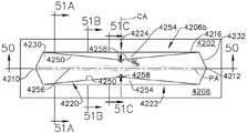
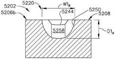
图32是具有限定于其中的多个钉成形凹坑的砧座的一部分的平面图;32 is a plan view of a portion of an anvil having a plurality of staple forming pockets defined therein;
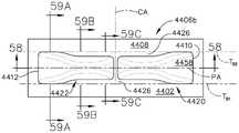
图33是图32的凹坑的细部图;Figure 33 is a detail view of the dimple of Figure 32;
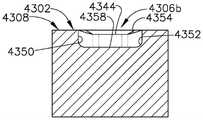
图34-35C是图33的凹坑的横剖视图;Figures 34-35C are cross-sectional views of the dimple of Figure 33;
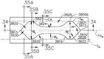
图36是具有限定于其中的多个钉成形凹坑的砧座的一部分的平面图;36 is a plan view of a portion of an anvil having a plurality of staple forming pockets defined therein;
图37是图36的凹坑的细部图;Figure 37 is a detail view of the dimple of Figure 36;
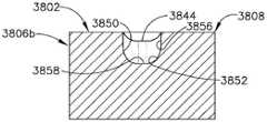
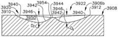
图38-39C是图37的凹坑的横剖视图;Figures 38-39C are cross-sectional views of the dimple of Figure 37;
图40是具有限定于其中的多个钉成形凹坑的砧座的一部分的平面图;40 is a plan view of a portion of an anvil having a plurality of staple forming pockets defined therein;
图41是图40的凹坑的细部图;Figure 41 is a detail view of the dimple of Figure 40;
图42-43C是图41的凹坑的横剖视图;Figures 42-43C are cross-sectional views of the dimple of Figure 41;
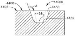
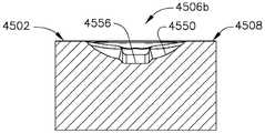
图44是具有限定于其中的多个钉成形凹坑的砧座的一部分的平面图;44 is a plan view of a portion of an anvil having a plurality of staple forming pockets defined therein;
图45是图44的凹坑的细部图;Figure 45 is a detail view of the dimple of Figure 44;
图46-47C是图45的凹坑的横剖视图;Figures 46-47C are cross-sectional views of the dimple of Figure 45;
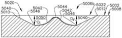
图48是具有限定于其中的多个钉成形凹坑的砧座的一部分的平面图;48 is a plan view of a portion of an anvil having a plurality of staple forming pockets defined therein;
图49是图48的凹坑的细部图;Figure 49 is a detail view of the dimple of Figure 48;
图50-51C是图49的凹坑的横剖视图;Figures 50-51C are cross-sectional views of the dimple of Figure 49;
图52是具有限定于其中的多个钉成形凹坑的砧座的一部分的平面图;52 is a plan view of a portion of an anvil having a plurality of staple forming pockets defined therein;
图53是图52的凹坑的细部图;Figure 53 is a detail view of the dimple of Figure 52;
图54-55C是图53的凹坑的横剖视图;Figures 54-55C are cross-sectional views of the dimple of Figure 53;
图56是具有限定于其中的多个钉成形凹坑的砧座的一部分的平面图;56 is a plan view of a portion of an anvil having a plurality of staple forming pockets defined therein;
图57是图56的凹坑的细部图;Figure 57 is a detail view of the dimple of Figure 56;
图58-59C是图57的凹坑的横剖视图;Figures 58-59C are cross-sectional views of the dimple of Figure 57;
图60是具有限定于其中的多个钉成形凹坑的砧座的一部分的平面图;60 is a plan view of a portion of an anvil having a plurality of staple forming pockets defined therein;
图61是图60的凹坑的细部图;Figure 61 is a detail view of the dimple of Figure 60;
图62-63C是图61的凹坑的横剖视图;Figures 62-63C are cross-sectional views of the dimple of Figure 61;
图64是具有限定于其中的多个钉成形凹坑的砧座的一部分的平面图;64 is a plan view of a portion of an anvil having a plurality of staple forming pockets defined therein;
图65是图64的凹坑的细部图;Figure 65 is a detail view of the dimple of Figure 64;
图66-67C是图65的凹坑的横剖视图;Figures 66-67C are cross-sectional views of the dimple of Figure 65;
图68是具有限定于其中的多个钉成形凹坑的砧座的一部分的平面图;68 is a plan view of a portion of an anvil having a plurality of staple forming pockets defined therein;
图69是图68的凹坑的细部图;Figure 69 is a detail view of the dimple of Figure 68;
图70-71C是图69的凹坑的横剖视图;Figures 70-71C are cross-sectional views of the dimple of Figure 69;
图72是具有限定于其中的多个钉成形凹坑的砧座的一部分的平面图;72 is a plan view of a portion of an anvil having a plurality of staple forming pockets defined therein;
图73是图72的凹坑的细部图;Figure 73 is a detail view of the dimple of Figure 72;
图74-76C是图73 的凹坑的横剖视图;Figures 74-76C are cross-sectional views of the dimple of Figure 73;
图77是端部执行器和适配器组件的分解透视图;Figure 77 is an exploded perspective view of the end effector and adapter assembly;
图78是图77的端部执行器和适配器组件的一部分的剖面透视图;Figure 78 is a cutaway perspective view of a portion of the end effector and adapter assembly of Figure 77;
图79是图77的端部执行器和适配器组件的剖面透视图;Figure 79 is a cutaway perspective view of the end effector and adapter assembly of Figure 77;
图80是具有限定于其中的多个钉成形凹坑的砧座的一部分的平面图;80 is a plan view of a portion of an anvil having a plurality of staple forming pockets defined therein;
图81是钉驱动器实施方案的顶视图;Figure 81 is a top view of a staple driver embodiment;
图82是图81的钉驱动器实施方案的顶部透视图;并且Figure 82 is a top perspective view of the staple driver embodiment of Figure 81; and
图83是图81和图82的钉驱动器实施方案的底部透视图。83 is a bottom perspective view of the staple driver embodiment of FIGS. 81 and 82. FIG.
在所述若干视图中,对应的参考符号指示对应的部件。本文所述的范例以一种形式示出了本发明的各种实施方案,且这种范例不应被解释为以任何方式限制本发明的范围。Corresponding reference characters indicate corresponding parts throughout the several views. The exemplifications described herein illustrate various embodiments of the invention in one form, and such exemplifications should not be construed to limit the scope of the invention in any way.
具体实施方式Detailed ways
本申请的申请人拥有与本申请于同一日期提交且各自全文以引用方式并入本文的以下美国专利申请:The applicant of the present application has the following US patent applications filed on the same date as the present application and each of which is incorporated herein by reference in its entirety:
-名称为“SURGICAL STAPLING INSTRUMENTS AND REPLACEABLE TOOL ASSEMBLIESTHEREOF”的美国专利申请序列号15/386,185;- US Patent Application Serial No. 15/386,185 entitled "SURGICAL STAPLING INSTRUMENTS AND REPLACEABLE TOOL ASSEMBLIESTHEREOF";
-名称为“ARTICULATABLE SURGICAL STAPLING INSTRUMENTS”的美国专利申请序列号15/386,230;- US Patent Application Serial No. 15/386,230 entitled "ARTICULATABLE SURGICAL STAPLING INSTRUMENTS";
-名称为“LOCKOUT ARRANGEMENTS FOR SURGICAL END EFFECTORS”的美国专利申请序列号15/386,221;- US Patent Application Serial No. 15/386,221 entitled "LOCKOUT ARRANGEMENTS FOR SURGICAL END EFFECTORS";
-名称为“SURGICAL END EFFECTORS AND FIRING MEMBERS THEREOF”的美国专利申请序列号15/386,209;- US Patent Application Serial No. 15/386,209 entitled "SURGICAL END EFFECTORS AND FIRING MEMBERS THEREOF";
-名称为“LOCKOUT ARRANGEMENTS FOR SURGICAL END EFFECTORS ANDREPLACEABLE TOOL ASSEMBLIES”的美国专利申请序列号15/386,198;以及- US Patent Application Serial No. 15/386,198 entitled "LOCKOUT ARRANGEMENTS FOR SURGICAL END EFFECTORS ANDREPLACEABLE TOOL ASSEMBLIES"; and
-名称为“SURGICAL END EFFECTORS AND ADAPTABLE FIRING MEMBERS THEREFOR”的美国专利申请序列号15/386,240。- US Patent Application Serial No. 15/386,240 entitled "SURGICAL END EFFECTORS AND ADAPTABLE FIRING MEMBERS THEREFOR".
本申请的申请人拥有与本申请于同一日期提交且各自全文以引用方式并入本文的以下美国专利申请:The applicant of the present application has the following US patent applications filed on the same date as the present application and each of which is incorporated herein by reference in its entirety:
-名称为“STAPLE CARTRIDGES AND ARRANGEMENTS OF STAPLES AND STAPLECAVITIES THEREIN”的美国专利申请序列号15/385,939;- US Patent Application Serial No. 15/385,939 entitled "STAPLE CARTRIDGES AND ARRANGEMENTS OF STAPLES AND STAPLECAVITIES THEREIN";
-名称为“SURGICAL TOOL ASSEMBLIES WITH CLUTCHING ARRANGEMENTS FORSHIFTING BETWEEN CLOSURE SYSTEMS WITH CLOSURE STROKE REDUCTION FEATURES ANDARTICULATION AND FIRING SYSTEMS”的美国专利申请序列号15/385,941;- US Patent Application Serial No. 15/385,941 entitled "SURGICAL TOOL ASSEMBLIES WITH CLUTCHING ARRANGEMENTS FORSHIFTING BETWEEN CLOSURE SYSTEMS WITH CLOSURE STROKE REDUCTION FEATURES ANDARTICULATION AND FIRING SYSTEMS";
-名称为“SURGICAL STAPLING INSTRUMENTS AND STAPLE-FORMING ANVILS”的美国专利申请序列号15/385,943;- US Patent Application Serial No. 15/385,943 entitled "SURGICAL STAPLING INSTRUMENTS AND STAPLE-FORMING ANVILS";
-名称为“SURGICAL TOOL ASSEMBLIES WITH CLOSURE STROKE REDUCTIONFEATURES”的美国专利申请序列号 15/385,950;- US Patent Application Serial No. 15/385,950 entitled "SURGICAL TOOL ASSEMBLIES WITH CLOSURE STROKE REDUCTIONFEATURES";
-名称为“SURGICAL STAPLING INSTRUMENTS AND STAPLE-FORMING ANVILS”的美国专利申请序列号15/385,946;- US Patent Application Serial No. 15/385,946 entitled "SURGICAL STAPLING INSTRUMENTS AND STAPLE-FORMING ANVILS";
-名称为“SURGICAL INSTRUMENTS WITH JAW OPENING FEATURES FOR INCREASINGA JAW OPENING DISTANCE”的美国专利申请序列号15/385,951;- US Patent Application Serial No. 15/385,951 entitled "SURGICAL INSTRUMENTS WITH JAW OPENING FEATURES FOR INCREASINGA JAW OPENING DISTANCE";
-名称为“METHODS OF STAPLING TISSUE”的美国专利申请序列号15/385,953;- US Patent Application Serial No. 15/385,953 entitled "METHODS OF STAPLING TISSUE";
-名称为“FIRING MEMBERS WITH NON-PARALLEL JAW ENGAGEMENT FEATURES FORSURGICAL END EFFECTORS”的美国专利申请序列号15/385,954;- US Patent Application Serial No. 15/385,954 entitled "FIRING MEMBERS WITH NON-PARALLEL JAW ENGAGEMENT FEATURES FORSURGICAL END EFFECTORS";
-名称为“SURGICAL END EFFECTORS WITH EXPANDABLE TISSUE STOPARRANGEMENTS”的美国专利申请序列号 15/385,955;- US Patent Application Serial No. 15/385,955 entitled "SURGICAL END EFFECTORS WITH EXPANDABLE TISSUE STOPARRANGEMENTS";
-名称为“SURGICAL STAPLING INSTRUMENTS AND STAPLE-FORMING ANVILS”的美国专利申请序列号15/385,948;- US Patent Application Serial No. 15/385,948 entitled "SURGICAL STAPLING INSTRUMENTS AND STAPLE-FORMING ANVILS";
-名称为“SURGICAL INSTRUMENTS WITH POSITIVE JAW OPENING FEATURES”的美国专利申请序列号15/385,956;- US Patent Application Serial No. 15/385,956 entitled "SURGICAL INSTRUMENTS WITH POSITIVE JAW OPENING FEATURES";
-名称为“SURGICAL INSTRUMENTS WITH LOCKOUT ARRANGEMENTS FOR PREVENTINGFIRING SYSTEM ACTUATION UNLESS AN UNSPENT STAPLE CARTRIDGE IS PRESENT”的美国专利申请序列号15/385,958;以及- US Patent Application Serial No. 15/385,958 entitled "SURGICAL INSTRUMENTS WITH LOCKOUT ARRANGEMENTS FOR PREVENTINGFIRING SYSTEM ACTUATION UNLESS AN UNSPENT STAPLE CARTRIDGE IS PRESENT"; and
-名称为“STAPLE CARTRIDGES AND ARRANGEMENTS OF STAPLES AND STAPLECAVITIES THEREIN”的美国专利申请序列号15/385,947。- US Patent Application Serial No. 15/385,947 entitled "STAPLE CARTRIDGES AND ARRANGEMENTS OF STAPLES AND STAPLECAVITIES THEREIN".
本申请的申请人拥有与本申请于同一日期提交且各自全文以引用方式并入本文的以下美国专利申请:The applicant of the present application has the following US patent applications filed on the same date as the present application and each of which is incorporated herein by reference in its entirety:
-名称为“METHOD FOR RESETTING A FUSE OF A SURGICAL INSTRUMENT SHAFT”的美国专利申请序列号15/385,896;- US Patent Application Serial No. 15/385,896 entitled "METHOD FOR RESETTING A FUSE OF A SURGICAL INSTRUMENT SHAFT";
-名称为“STAPLE FORMING POCKET ARRANGEMENT TO ACCOMMODATE DIFFERENTTYPES OF STAPLES”的美国专利申请序列号15/385,898;- US Patent Application Serial No. 15/385,898 entitled "STAPLE FORMING POCKET ARRANGEMENT TO ACCOMMODATE DIFFERENTTYPES OF STAPLES";
-名称为“SURGICAL INSTRUMENT COMPRISING IMPROVED JAW CONTROL”的美国专利申请序列号15/385,899;- US Patent Application Serial No. 15/385,899 entitled "SURGICAL INSTRUMENT COMPRISING IMPROVED JAW CONTROL";
-名称为“STAPLE CARTRIDGE AND STAPLE CARTRIDGE CHANNEL COMPRISINGWINDOWS DEFINED THEREIN”的美国专利申请序列号15/385,901;- US Patent Application Serial No. 15/385,901 entitled "STAPLE CARTRIDGE AND STAPLE CARTRIDGE CHANNEL COMPRISING WINDOWS DEFINED THEREIN";
-名称为“SURGICAL INSTRUMENT COMPRISING A CUTTING MEMBER”的美国专利申请序列号15/385,902;- US Patent Application Serial No. 15/385,902 entitled "SURGICAL INSTRUMENT COMPRISING A CUTTING MEMBER";
-名称为“STAPLE FIRING MEMBER COMPRISING A MISSING CARTRIDGE AND/ORSPENT CARTRIDGE LOCKOUT”的美国专利申请序列号15/385,904;- US Patent Application Serial No. 15/385,904 entitled "STAPLE FIRING MEMBER COMPRISING A MISSING CARTRIDGE AND/ORSPENT CARTRIDGE LOCKOUT";
-名称为“FIRING ASSEMBLY COMPRISING A LOCKOUT”的美国专利申请序列号15/385,905;- US Patent Application Serial No. 15/385,905 entitled "FIRING ASSEMBLY COMPRISING A LOCKOUT";
-名称为“SURGICAL INSTRUMENT SYSTEM COMPRISING AN END EFFECTOR LOCKOUTAND A FIRING ASSEMBLY LOCKOUT”的美国专利申请序列号15/385,907;- US Patent Application Serial No. 15/385,907 entitled "SURGICAL INSTRUMENT SYSTEM COMPRISING AN END EFFECTOR LOCKOUTAND A FIRING ASSEMBLY LOCKOUT";
-名称为“FIRING ASSEMBLY COMPRISING A FUSE”的美国专利申请序列号15/385,908;以及- US Patent Application Serial No. 15/385,908 entitled "FIRING ASSEMBLY COMPRISING A FUSE"; and
-名称为“FIRING ASSEMBLY COMPRISING A MULTIPLE FAILED-STATE FUSE”的美国专利申请序列号15/385,909。- US Patent Application Serial No. 15/385,909 entitled "FIRING ASSEMBLY COMPRISING A MULTIPLE FAILED-STATE FUSE".
本申请的申请人拥有与本申请于同一日期提交且各自全文以引用方式并入本文的以下美国专利申请:The applicant of the present application has the following US patent applications filed on the same date as the present application and each of which is incorporated herein by reference in its entirety:
-名称为“STAPLE FORMING POCKET ARRANGEMENTS”的美国专利申请序列号15/385,920;- US Patent Application Serial No. 15/385,920 entitled "STAPLE FORMING POCKET ARRANGEMENTS";
-名称为“ANVIL ARRANGEMENTS FOR SURGICAL STAPLERS”的美国专利申请序列号15/385,913;- US Patent Application Serial No. 15/385,913 entitled "ANVIL ARRANGEMENTS FOR SURGICAL STAPLERS";
-名称为“METHOD OF DEFORMING STAPLES FROM TWO DIFFERENT TYPES OFSTAPLE CARTRIDGES WITH THE SAME SURGICAL STAPLING INSTRUMENT”的美国专利申请序列号 15/385,914;- US Patent Application Serial No. 15/385,914 entitled "METHOD OF DEFORMING STAPLES FROM TWO DIFFERENT TYPES OFSTAPLE CARTRIDGES WITH THE SAME SURGICAL STAPLING INSTRUMENT";
-名称为“BILATERALLY ASYMMETRIC STAPLE FORMING POCKET PAIRS”的美国专利申请序列号15/385,893;- US Patent Application Serial No. 15/385,893 entitled "BILATERALLY ASYMMETRIC STAPLE FORMING POCKET PAIRS";
-名称为“CLOSURE MEMBERS WITH CAM SURFACE ARRANGEMENTS FOR SURGICALINSTRUMENTS WITH SEPARATE AND DISTINCT CLOSURE AND FIRING SYSTEMS”的美国专利申请序列号15/385,929;- US Patent Application Serial No. 15/385,929 entitled "CLOSURE MEMBERS WITH CAM SURFACE ARRANGEMENTS FOR SURGICALINSTRUMENTS WITH SEPARATE AND DISTINCT CLOSURE AND FIRING SYSTEMS";
-名称为“SURGICAL STAPLERS WITH INDEPENDENTLY ACTUATABLE CLOSING ANDFIRING SYSTEMS”的美国专利申请序列号15/385,911;- US Patent Application Serial No. 15/385,911 entitled "SURGICAL STAPLERS WITH INDEPENDENTLY ACTUATABLE CLOSING ANDFIRING SYSTEMS";
-名称为“SURGICAL STAPLING INSTRUMENTS WITH SMART STAPLE CARTRIDGES”的美国专利申请序列号15/385,927;- US Patent Application Serial No. 15/385,927 entitled "SURGICAL STAPLING INSTRUMENTS WITH SMART STAPLE CARTRIDGES";
-名称为“STAPLE CARTRIDGE COMPRISING STAPLES WITH DIFFERENT CLAMPINGBREADTHS”的美国专利申请序列号 15/385,917;- US Patent Application Serial No. 15/385,917 entitled "STAPLE CARTRIDGE COMPRISING STAPLES WITH DIFFERENT CLAMPINGBREADTHS";
-名称为“STAPLE FORMING POCKET ARRANGEMENTS COMPRISING PRIMARYSIDEWALLS AND POCKET SIDEWALLS”的美国专利申请序列号15/385,900;- US Patent Application Serial No. 15/385,900 entitled "STAPLE FORMING POCKET ARRANGEMENTS COMPRISING PRIMARYSIDEWALLS AND POCKET SIDEWALLS";
-名称为“NO-CARTRIDGE AND SPENT CARTRIDGE LOCKOUT ARRANGEMENTS FORSURGICAL STAPLERS”的美国专利申请序列号15/385,931;- US Patent Application Serial No. 15/385,931 entitled "NO-CARTRIDGE AND SPENT CARTRIDGE LOCKOUT ARRANGEMENTS FORSURGICAL STAPLERS";
-名称为“FIRING MEMBER PIN ANGLE”的美国专利申请序列号 15/385,915;- US Patent Application Serial No. 15/385,915 entitled "FIRING MEMBER PIN ANGLE";
-名称为“STAPLE FORMING POCKET ARRANGEMENTS COMPRISING ZONED FORMINGSURFACE GROOVES”的美国专利申请序列号15/385,897;- US Patent Application Serial No. 15/385,897 entitled "STAPLE FORMING POCKET ARRANGEMENTS COMPRISING ZONED FORMINGSURFACE GROOVES";
-名称为“SURGICAL INSTRUMENT WITH MULTIPLE FAILURE RESPONSE MODES”的美国专利申请序列号15/385,922;- US Patent Application Serial No. 15/385,922 entitled "SURGICAL INSTRUMENT WITH MULTIPLE FAILURE RESPONSE MODES";
-名称为“SURGICAL INSTRUMENT WITH PRIMARY AND SAFETY PROCESSORS”的美国专利申请序列号15/385,924;- US Patent Application Serial No. 15/385,924 entitled "SURGICAL INSTRUMENT WITH PRIMARY AND SAFETY PROCESSORS";
-名称为“SURGICAL INSTRUMENTS WITH JAWS THAT ARE PIVOTABLE ABOUT AFIXED AXIS AND INCLUDE SEPARATE AND DISTINCT CLOSURE AND FIRING SYSTEMS”的美国专利申请序列号15/385,912;- US Patent Application Serial No. 15/385,912 entitled "SURGICAL INSTRUMENTS WITH JAWS THAT ARE PIVOTABLE ABOUT AFIXED AXIS AND INCLUDE SEPARATE AND DISTINCT CLOSURE AND FIRING SYSTEMS";
-名称为“ANVIL HAVING A KNIFE SLOT WIDTH”的美国专利申请序列号15/385,910;- US Patent Application Serial No. 15/385,910 entitled "ANVIL HAVING A KNIFE SLOT WIDTH";
-名称为“CLOSURE MEMBER ARRANGEMENTS FOR SURGICAL INSTRUMENTS”的美国专利申请序列号15/385,903;以及- US Patent Application Serial No. 15/385,903 entitled "CLOSURE MEMBER ARRANGEMENTS FOR SURGICAL INSTRUMENTS"; and
-名称为“FIRING MEMBER PIN CONFIGURATIONS”的美国专利申请序列号15/385,906。- US Patent Application Serial No. 15/385,906 entitled "FIRING MEMBER PIN CONFIGURATIONS".
本申请的申请人拥有与本申请于同一日期提交且各自全文以引用方式并入本文的以下美国专利申请:The applicant of the present application has the following US patent applications filed on the same date as the present application and each of which is incorporated herein by reference in its entirety:
-名称为“STEPPED STAPLE CARTRIDGE WITH ASYMMETRICAL STAPLES”的美国专利申请序列号15/386,188;- US Patent Application Serial No. 15/386,188 entitled "STEPPED STAPLE CARTRIDGE WITH ASYMMETRICAL STAPLES";
-名称为“STEPPED STAPLE CARTRIDGE WITH TISSUE RETENTION AND GAPSETTING FEATURES”的美国专利申请序列号15/386,192;- US Patent Application Serial No. 15/386,192 entitled "STEPPED STAPLE CARTRIDGE WITH TISSUE RETENTION AND GAPSETTING FEATURES";
-名称为“STAPLE CARTRIDGE WITH DEFORMABLE DRIVER RETENTION FEATURES”的美国专利申请序列号15/386,206;- US Patent Application Serial No. 15/386,206 entitled "STAPLE CARTRIDGE WITH DEFORMABLE DRIVER RETENTION FEATURES";
-名称为“DURABILITY FEATURES FOR END EFFECTORS AND FIRING ASSEMBLIESOF SURGICAL STAPLING INSTRUMENTS”的美国专利申请序列号15/386,226;- US Patent Application Serial No. 15/386,226 entitled "DURABILITY FEATURES FOR END EFFECTORS AND FIRING ASSEMBLIESOF SURGICAL STAPLING INSTRUMENTS";
-名称为“SURGICAL STAPLING INSTRUMENTS HAVING END EFFECTORS WITHPOSITIVE OPENING FEATURES”的美国专利申请序列号15/386,222;以及- US Patent Application Serial No. 15/386,222 entitled "SURGICAL STAPLING INSTRUMENTS HAVING END EFFECTORS WITHPOSITIVE OPENING FEATURES"; and
-名称为“CONNECTION PORTIONS FOR DISPOSABLE LOADING UNITS FOR SURGICALSTAPLING INSTRUMENTS”的美国专利申请序列号15/386,236。- US Patent Application Serial No. 15/386,236 entitled "CONNECTION PORTIONS FOR DISPOSABLE LOADING UNITS FOR SURGICALSTAPLING INSTRUMENTS".
本申请的申请人拥有与本申请于同一日期提交且各自全文以引用方式并入本文的以下美国专利申请:The applicant of the present application has the following US patent applications filed on the same date as the present application and each of which is incorporated herein by reference in its entirety:
-名称为“METHOD FOR ATTACHING A SHAFT ASSEMBLY TO A SURGICALINSTRUMENT AND,ALTERNATIVELY,TO A SURGICAL ROBOT”的美国专利申请序列号15/385,887;- US Patent Application Serial No. 15/385,887 entitled "METHOD FOR ATTACHING A SHAFT ASSEMBLY TO A SURGICALINSTRUMENT AND, ALTERNATIVELY, TO A SURGICAL ROBOT";
-名称为“SHAFT ASSEMBLY COMPRISING A MANUALLY-OPERABLE RETRACTIONSYSTEM FOR USE WITH A MOTORIZED SURGICAL INSTRUMENT SYSTEM”的美国专利申请序列号15/385,889;- US Patent Application Serial No. 15/385,889 entitled "SHAFT ASSEMBLY COMPRISING A MANUALLY-OPERABLE RETRACTION SYSTEM FOR USE WITH A MOTORIZED SURGICAL INSTRUMENT SYSTEM";
-名称为“SHAFT ASSEMBLY COMPRISING SEPARATELY ACTUATABLE ANDRETRACTABLE SYSTEMS”的美国专利申请序列号15/385,890;- US Patent Application Serial No. 15/385,890 entitled "SHAFT ASSEMBLY COMPRISING SEPARATELY ACTUATABLE ANDRETRACTABLE SYSTEMS";
-名称为“SHAFT ASSEMBLY COMPRISING A CLUTCH CONFIGURED TO ADAPT THEOUTPUT OF A ROTARY FIRING MEMBER TO TWO DIFFERENT SYSTEMS”的美国专利申请序列号15/385,891;- US Patent Application Serial No. 15/385,891 entitled "SHAFT ASSEMBLY COMPRISING A CLUTCH CONFIGURED TO ADAPT THEOUTPUT OF A ROTARY FIRING MEMBER TO TWO DIFFERENT SYSTEMS";
-名称为“SURGICAL SYSTEM COMPRISING A FIRING MEMBER ROTATABLE INTO ANARTICULATION STATE TO ARTICULATE AN END EFFECTOR OF THE SURGICAL SYSTEM”的美国专利申请序列号15/385,892;- US Patent Application Serial No. 15/385,892 entitled "SURGICAL SYSTEM COMPRISING A FIRING MEMBER ROTATABLE INTO ANARTICULATION STATE TO ARTICULATE AN END EFFECTOR OF THE SURGICAL SYSTEM";
-名称为“SHAFT ASSEMBLY COMPRISING A LOCKOUT”的美国专利申请序列号15/385,894;以及- US Patent Application Serial No. 15/385,894 entitled "SHAFT ASSEMBLY COMPRISING A LOCKOUT"; and
-名称为“SHAFT ASSEMBLY COMPRISING FIRST AND SECOND ARTICULATIONLOCKOUTS”的美国专利申请序列号15/385,895。- US Patent Application Serial No. 15/385,895 entitled "SHAFT ASSEMBLY COMPRISING FIRST AND SECOND ARTICULATION LOCKOUTS".
本申请的申请人拥有与本申请于同一日期提交且各自全文以引用方式并入本文的以下美国专利申请:The applicant of the present application has the following US patent applications filed on the same date as the present application and each of which is incorporated herein by reference in its entirety:
-名称为“SURGICAL STAPLING SYSTEMS”的美国专利申请序列号15/385,916;- US Patent Application Serial No. 15/385,916 entitled "SURGICAL STAPLING SYSTEMS";
-名称为“SURGICAL STAPLING SYSTEMS”的美国专利申请序列号15/385,918;- US Patent Application Serial No. 15/385,918 entitled "SURGICAL STAPLING SYSTEMS";
-名称为“SURGICAL STAPLING SYSTEMS”的美国专利申请序列号15/385,919;- US Patent Application Serial No. 15/385,919 entitled "SURGICAL STAPLING SYSTEMS";
-名称为“SURGICAL STAPLE CARTRIDGE WITH MOVABLE CAMMING MEMBERCONFIGURED TO DISENGAGE FIRING MEMBER LOCKOUT FEATURES”的美国专利申请序列号15/385,921;- US Patent Application Serial No. 15/385,921 entitled "SURGICAL STAPLE CARTRIDGE WITH MOVABLE CAMMING MEMBERCONFIGURED TO DISENGAGE FIRING MEMBER LOCKOUT FEATURES";
-名称为“SURGICAL STAPLING SYSTEMS”的美国专利申请序列号15/385,923;- US Patent Application Serial No. 15/385,923 entitled "SURGICAL STAPLING SYSTEMS";
-名称为“JAW ACTUATED LOCK ARRANGEMENTS FOR PREVENTING ADVANCEMENT OFA FIRING MEMBER IN A SURGICAL END EFFECTOR UNLESS AN UNFIRED CARTRIDGE ISINSTALLED IN THE END EFFECTOR”的美国专利申请序列号 15/385,925;- US Patent Application Serial No. 15/385,925 entitled "JAW ACTUATED LOCK ARRANGEMENTS FOR PREVENTING ADVANCEMENT OFA FIRING MEMBER IN A SURGICAL END EFFECTOR UNLESS AN UNFIRED CARTRIDGE ISINSTALLED IN THE END EFFECTOR";
-名称为“AXIALLY MOVABLE CLOSURE SYSTEM ARRANGEMENTS FOR APPLYINGCLOSURE MOTIONS TO JAWS OF SURGICAL INSTRUMENTS”的美国专利申请序列号 15/385,926;- US Patent Application Serial No. 15/385,926 entitled "AXIALLY MOVABLE CLOSURE SYSTEM ARRANGEMENTS FOR APPLYINGCLOSURE MOTIONS TO JAWS OF SURGICAL INSTRUMENTS";
-名称为“PROTECTIVE COVER ARRANGEMENTS FOR A JOINT INTERFACE BETWEEN AMOVABLE JAW AND ACTUATOR SHAFT OF A SURGICAL INSTRUMENT”的美国专利申请序列号15/385,928;- US Patent Application Serial No. 15/385,928 entitled "PROTECTIVE COVER ARRANGEMENTS FOR A JOINT INTERFACE BETWEEN AMOVABLE JAW AND ACTUATOR SHAFT OF A SURGICAL INSTRUMENT";
-名称为“SURGICAL END EFFECTOR WITH TWO SEPARATE COOPERATING OPENINGFEATURES FOR OPENING AND CLOSING END EFFECTOR JAWS”的美国专利申请序列号 15/385,930;- US Patent Application Serial No. 15/385,930 entitled "SURGICAL END EFFECTOR WITH TWO SEPARATE COOPERATING OPENINGFEATURES FOR OPENING AND CLOSING END EFFECTOR JAWS";
-名称为“ARTICULATABLE SURGICAL END EFFECTOR WITH ASYMMETRIC SHAFTARRANGEMENT”的美国专利申请序列号 15/385,932;- US Patent Application Serial No. 15/385,932 entitled "ARTICULATABLE SURGICAL END EFFECTOR WITH ASYMMETRIC SHAFTARRANGEMENT";
-名称为“ARTICULATABLE SURGICAL INSTRUMENT WITH INDEPENDENT PIVOTABLELINKAGE DISTAL OF AN ARTICULATION LOCK”的美国专利申请序列号15/385,933;- US Patent Application Serial No. 15/385,933 entitled "ARTICULATABLE SURGICAL INSTRUMENT WITH INDEPENDENT PIVOTABLELINKAGE DISTAL OF AN ARTICULATION LOCK";
-名称为“ARTICULATION LOCK ARRANGEMENTS FOR LOCKING AN END EFFECTOR INAN ARTICULATED POSITION IN RESPONSE TO ACTUATION OF A JAW CLOSURE SYSTEM”的美国专利申请序列号15/385,934;- US Patent Application Serial No. 15/385,934 entitled "ARTICULATION LOCK ARRANGEMENTS FOR LOCKING AN END EFFECTOR INAN ARTICULATED POSITION IN RESPONSE TO ACTUATION OF A JAW CLOSURE SYSTEM";
-名称为“LATERALLY ACTUATABLE ARTICULATION LOCK ARRANGEMENTS FORLOCKING AN END EFFECTOR OF A SURGICAL INSTRUMENT IN AN ARTICULATEDCONFIGURATION”的美国专利申请序列号15/385,935;以及- US Patent Application Serial No. 15/385,935 entitled "LATERALLY ACTUATABLE ARTICULATION LOCK ARRANGEMENTS FORLOCKING AN END EFFECTOR OF A SURGICAL INSTRUMENT IN AN ARTICULATED CONFIGURATION"; and
-名称为“ARTICULATABLE SURGICAL INSTRUMENTS WITH ARTICULATION STROKEAMPLIFICATION FEATURES”的美国专利申请序列号15/385,936。- US Patent Application Serial No. 15/385,936 entitled "ARTICULATABLE SURGICAL INSTRUMENTS WITH ARTICULATION STROKEAMPLIFICATION FEATURES".
本申请的申请人拥有于2016年6月24日提交且各自全文以引用方式并入本文的以下美国专利申请:The applicant of the present application has the following US patent applications filed on June 24, 2016, each of which is incorporated herein by reference in its entirety:
-名称为“STAPLE CARTRIDGE COMPRISING WIRE STAPLES AND STAMPED STAPLES”的美国专利申请序列号15/191,775;- US Patent Application Serial No. 15/191,775 entitled "STAPLE CARTRIDGE COMPRISING WIRE STAPLES AND STAMPED STAPLES";
-名称为“STAPLING SYSTEM FOR USE WITH WIRE STAPLES AND STAMPEDSTAPLES”的美国专利申请序列号15/191,807;- US Patent Application Serial No. 15/191,807 entitled "STAPLING SYSTEM FOR USE WITH WIRE STAPLES AND STAMPEDSTAPLES";
-名称为“STAMPED STAPLES AND STAPLE CARTRIDGES USING THE SAME”的美国专利申请序列号15/191,834;- US Patent Application Serial No. 15/191,834 entitled "STAMPED STAPLES AND STAPLE CARTRIDGES USING THE SAME";
-名称为“STAPLE CARTRIDGE COMPRISING OVERDRIVEN STAPLES”的美国专利申请序列号15/191,788;以及- US Patent Application Serial No. 15/191,788 entitled "STAPLE CARTRIDGE COMPRISING OVERDRIVEN STAPLES"; and
-名称为“STAPLE CARTRIDGE COMPRISING OFFSET LONGITUDINAL STAPLE ROWS”的美国专利申请序列号 15/191,818。- US Patent Application Serial No. 15/191,818 entitled "STAPLE CARTRIDGE COMPRISING OFFSET LONGITUDINAL STAPLE ROWS".
本申请的申请人拥有于2016年6月24日提交且各自全文以引用方式并入本文的以下美国专利申请:The applicant of the present application has the following US patent applications filed on June 24, 2016, each of which is incorporated herein by reference in its entirety:
-名称为“SURGICAL FASTENER”的美国设计专利申请序列号 29/569,218;- US Design Patent Application Serial No. 29/569,218 entitled "SURGICAL FASTENER";
-名称为“SURGICAL FASTENER”的美国设计专利申请序列号 29/569,227;- US Design Patent Application Serial No. 29/569,227 entitled "SURGICAL FASTENER";
-名称为“SURGICAL FASTENER CARTRIDGE”的美国设计专利申请序列号29/569,259;以及- US Design Patent Application Serial No. 29/569,259 entitled "SURGICAL FASTENER CARTRIDGE"; and
-名称为“SURGICAL FASTENER CARTRIDGE”的美国设计专利申请序列号29/569,264。- US Design Patent Application Serial No. 29/569,264 entitled "SURGICAL FASTENER CARTRIDGE".
本申请的申请人拥有于2016年4月1日提交且各自全文以引用方式并入本文的以下专利申请:The applicant of the present application has the following patent applications filed on April 1, 2016, each of which is incorporated herein by reference in its entirety:
-名称为“METHOD FOR OPERATING A SURGICAL STAPLING SYSTEM”的美国专利申请序列号15/089,325;- US Patent Application Serial No. 15/089,325 entitled "METHOD FOR OPERATING A SURGICAL STAPLING SYSTEM";
-名称为“MODULAR SURGICAL STAPLING SYSTEM COMPRISING A DISPLAY”的美国专利申请序列号15/089,321;- US Patent Application Serial No. 15/089,321 entitled "MODULAR SURGICAL STAPLING SYSTEM COMPRISING A DISPLAY";
-名称为“SURGICAL STAPLING SYSTEM COMPRISING A DISPLAY INCLUDING A RE-ORIENTABLE DISPLAY FIELD”的美国专利申请序列号15/089,326;- US Patent Application Serial No. 15/089,326 entitled "SURGICAL STAPLING SYSTEM COMPRISING A DISPLAY INCLUDING A RE-ORIENTABLE DISPLAY FIELD";
-名称为“SURGICAL INSTRUMENT HANDLE ASSEMBLY WITH RECONFIGURABLE GRIPPORTION”的美国专利申请序列号 15/089,263;- US Patent Application Serial No. 15/089,263 entitled "SURGICAL INSTRUMENT HANDLE ASSEMBLY WITH RECONFIGURABLE GRIPPORTION";
-名称为“ROTARY POWERED SURGICAL INSTRUMENT WITH MANUALLY ACTUATABLEBAILOUT SYSTEM”的美国专利申请序列号15/089,262;- US Patent Application Serial No. 15/089,262 entitled "ROTARY POWERED SURGICAL INSTRUMENT WITH MANUALLY ACTUATABLEBAILOUT SYSTEM";
-名称为“SURGICAL CUTTING AND STAPLING END EFFECTOR WITH ANVILCONCENTRIC DRIVE MEMBER”的美国专利申请序列号15/089,277;- US Patent Application Serial No. 15/089,277 entitled "SURGICAL CUTTING AND STAPLING END EFFECTOR WITH ANVILCONCENTRIC DRIVE MEMBER";
-名称为“INTERCHANGEABLE SURGICAL TOOL ASSEMBLY WITH A SURGICAL ENDEFFECTOR THAT IS SELECTIVELY ROTATABLE ABOUT A SHAFT AXIS”的美国专利申请序列号 15/089,296;- US Patent Application Serial No. 15/089,296 entitled "INTERCHANGEABLE SURGICAL TOOL ASSEMBLY WITH A SURGICAL ENDEFFECTOR THAT IS SELECTIVELY ROTATABLE ABOUT A SHAFT AXIS";
-名称为“SURGICAL STAPLING SYSTEM COMPRISING A SHIFTABLE TRANSMISSION”的美国专利申请序列号15/089,258; -名称为“SURGICAL STAPLING SYSTEM CONFIGUREDTO PROVIDE SELECTIVE CUTTING OF TISSUE”的美国专利申请序列号15/089,278;- US Patent Application Serial No. 15/089,258 entitled "SURGICAL STAPLING SYSTEM COMPRISING A SHIFTABLE TRANSMISSION"; - US Patent Application Serial No. 15/089,278 entitled "SURGICAL STAPLING SYSTEM CONFIGUREDTO PROVIDE SELECTIVE CUTTING OF TISSUE";
-名称为“SURGICAL STAPLING SYSTEM COMPRISING A CONTOURABLE SHAFT”的美国专利申请序列号15/089,284;- US Patent Application Serial No. 15/089,284 entitled "SURGICAL STAPLING SYSTEM COMPRISING A CONTOURABLE SHAFT";
-名称为“SURGICAL STAPLING SYSTEM COMPRISING A TISSUE COMPRESSIONLOCKOUT”的美国专利申请序列号15/089,295; -名称为“SURGICAL STAPLING SYSTEMCOMPRISING AN UNCLAMPING LOCKOUT”的美国专利申请序列号15/089,300; -名称为“SURGICAL STAPLING SYSTEM COMPRISING A JAW CLOSURE LOCKOUT”的美国专利申请序列号15/089,196;- US Patent Application Serial No. 15/089,295 entitled "SURGICAL STAPLING SYSTEM COMPRISING A TISSUE COMPRESSION LOCKOUT"; - US Patent Application Serial No. 15/089,300 entitled "SURGICAL STAPLING SYSTEM COMPRISING AN UNCLAMPING LOCKOUT"; - US Patent Application Serial No. 15/089,300 entitled "SURGICAL STAPLING SYSTEM COMPRISING AN UNCLAMPING LOCKOUT" COMPRISING A JAW CLOSURE LOCKOUT" U.S. Patent Application Serial No. 15/089,196;
-名称为“SURGICAL STAPLING SYSTEM COMPRISING A JAW ATTACHMENT LOCKOUT”的美国专利申请序列号15/089,203; -名称为“SURGICAL STAPLING SYSTEM COMPRISING ASPENT CARTRIDGE LOCKOUT”的美国专利申请序列号15/089,210;- US Patent Application Serial No. 15/089,203 entitled "SURGICAL STAPLING SYSTEM COMPRISING A JAW ATTACHMENT LOCKOUT"; - US Patent Application Serial No. 15/089,210 entitled "SURGICAL STAPLING SYSTEM COMPRISING ASPENT CARTRIDGE LOCKOUT";
-名称为“SURGICAL INSTRUMENT COMPRISING A SHIFTING MECHANISM”的美国专利申请序列号15/089,324;- US Patent Application Serial No. 15/089,324 entitled "SURGICAL INSTRUMENT COMPRISING A SHIFTING MECHANISM";
-名称为“SURGICAL STAPLING INSTRUMENT COMPRISING MULTIPLE LOCKOUTS”的美国专利申请序列号15/089,335;- US Patent Application Serial No. 15/089,335 entitled "SURGICAL STAPLING INSTRUMENT COMPRISING MULTIPLE LOCKOUTS";
-名称为“SURGICAL STAPLING INSTRUMENT”的美国专利申请序列号15/089,339;- US Patent Application Serial No. 15/089,339 entitled "SURGICAL STAPLING INSTRUMENT";
-名称为“SURGICAL STAPLING SYSTEM CONFIGURED TO APPLY ANNULAR ROWS OFSTAPLES HAVING DIFFERENT HEIGHTS”的美国专利申请序列号15/089,253;- US Patent Application Serial No. 15/089,253 entitled "SURGICAL STAPLING SYSTEM CONFIGURED TO APPLY ANNULAR ROWS OFSTAPLES HAVING DIFFERENT HEIGHTS";
-名称为“SURGICAL STAPLING SYSTEM COMPRISING A GROOVED FORMING POCKET”的美国专利申请序列号 15/089,304;- US Patent Application Serial No. 15/089,304 entitled "SURGICAL STAPLING SYSTEM COMPRISING A GROOVED FORMING POCKET";
-名称为“ANVIL MODIFICATION MEMBERS FOR SURGICAL STAPLERS”的美国专利申请序列号15/089,331;- US Patent Application Serial No. 15/089,331 entitled "ANVIL MODIFICATION MEMBERS FOR SURGICAL STAPLERS";
-名称为“STAPLE CARTRIDGES WITH ATRAUMATIC FEATURES”的美国专利申请序列号15/089,336;- US Patent Application Serial No. 15/089,336 entitled "STAPLE CARTRIDGES WITH ATRAUMATIC FEATURES";
-名称为“CIRCULAR STAPLING SYSTEM COMPRISING AN INCISABLE TISSUESUPPORT”的美国专利申请序列号 15/089,312;- US Patent Application Serial No. 15/089,312 entitled "CIRCULAR STAPLING SYSTEM COMPRISING AN INCISABLE TISSUESUPPORT";
-名称为“CIRCULAR STAPLING SYSTEM COMPRISING ROTARY FIRING SYSTEM”的美国专利申请序列号15/089,309;以及- US Patent Application Serial No. 15/089,309 entitled "CIRCULAR STAPLING SYSTEM COMPRISING ROTARY FIRING SYSTEM"; and
-名称为“CIRCULAR STAPLING SYSTEM COMPRISING LOAD CONTROL”的美国专利申请序列号15/089,349。- US Patent Application Serial No. 15/089,349 entitled "CIRCULAR STAPLING SYSTEM COMPRISING LOAD CONTROL".
本申请的申请人还拥有于2015年12月31日提交且各自全文以引用方式并入本文的如下标识的美国专利申请:The applicant of the present application also owns the following identified US patent applications filed on December 31, 2015, each of which is incorporated herein by reference in its entirety:
-名称为“MECHANISMS FOR COMPENSATING FOR BATTERY PACK FAILURE INPOWERED SURGICAL INSTRUMENTS”的美国专利申请序列号14/984,488;- US Patent Application Serial No. 14/984,488 entitled "MECHANISMS FOR COMPENSATING FOR BATTERY PACK FAILURE INPOWERED SURGICAL INSTRUMENTS";
-名称为“MECHANISMS FOR COMPENSATING FOR DRIVETRAIN FAILURE IN POWEREDSURGICAL INSTRUMENTS”的美国专利申请序列号14/984,525;以及- US Patent Application Serial No. 14/984,525 entitled "MECHANISMS FOR COMPENSATING FOR DRIVETRAIN FAILURE IN POWEREDSURGICAL INSTRUMENTS"; and
-名称为“SURGICAL INSTRUMENTS WITH SEPARABLE MOTORS AND MOTOR CONTROLCIRCUITS”的美国专利申请序列号 14/984,552。- US Patent Application Serial No. 14/984,552 entitled "SURGICAL INSTRUMENTS WITH SEPARABLE MOTORS AND MOTOR CONTROLCIRCUITS".
本申请的申请人还拥有于2016年2月9日提交且各自全文以引用方式并入本文的如下标识的美国专利申请:The applicant of the present application also owns the following identified US patent applications filed on February 9, 2016, each of which is incorporated herein by reference in its entirety:
-名称为“SURGICAL INSTRUMENT WITH ARTICULATING AND AXIALLYTRANSLATABLE END EFFECTOR”的美国专利申请序列号15/019,220;- US Patent Application Serial No. 15/019,220 entitled "SURGICAL INSTRUMENT WITH ARTICULATING AND AXIALLYTRANSLATABLE END EFFECTOR";
-名称为“SURGICAL INSTRUMENTS WITH MULTIPLE LINK ARTICULATIONARRANGEMENTS”的美国专利申请序列号 15/019,228;- US Patent Application Serial No. 15/019,228 entitled "SURGICAL INSTRUMENTS WITH MULTIPLE LINK ARTICULATION ARRANGEMENTS";
-名称为“SURGICAL INSTRUMENT ARTICULATION MECHANISM WITH SLOTTEDSECONDARY CONSTRAINT”的美国专利申请序列号15/019,196;- US Patent Application Serial No. 15/019,196 entitled "SURGICAL INSTRUMENT ARTICULATION MECHANISM WITH SLOTTED SECONDARY CONSTRAINT";
-名称为“SURGICAL INSTRUMENTS WITH AN END EFFECTOR THAT IS HIGHLYARTICULATABLE RELATIVE TO AN ELONGATE SHAFT ASSEMBLY”的美国专利申请序列号 15/019,206;- US Patent Application Serial No. 15/019,206 entitled "SURGICAL INSTRUMENTS WITH AN END EFFECTOR THAT IS HIGHLYARTICULATABLE RELATIVE TO AN ELONGATE SHAFT ASSEMBLY";
-名称为“SURGICAL INSTRUMENTS WITH NON-SYMMETRICAL ARTICULATIONARRANGEMENTS”的美国专利申请序列号 15/019,215;- US Patent Application Serial No. 15/019,215 entitled "SURGICAL INSTRUMENTS WITH NON-SYMMETRICAL ARTICULATION ARRANGEMENTS";
-名称为“ARTICULATABLE SURGICAL INSTRUMENTS WITH SINGLE ARTICULATIONLINK ARRANGEMENTS”的美国专利申请序列号15/019,227;- US Patent Application Serial No. 15/019,227 entitled "ARTICULATABLE SURGICAL INSTRUMENTS WITH SINGLE ARTICULATIONLINK ARRANGEMENTS";
-名称为“SURGICAL INSTRUMENTS WITH TENSIONING ARRANGEMENTS FOR CABLEDRIVEN ARTICULATION SYSTEMS”的美国专利申请序列号15/019,235;- US Patent Application Serial No. 15/019,235 entitled "SURGICAL INSTRUMENTS WITH TENSIONING ARRANGEMENTS FOR CABLEDRIVEN ARTICULATION SYSTEMS";
-名称为“ARTICULATABLE SURGICAL INSTRUMENTS WITH OFF-AXIS FIRING BEAMARRANGEMENTS”的美国专利申请序列号15/019,230;以及- US Patent Application Serial No. 15/019,230 entitled "ARTICULATABLE SURGICAL INSTRUMENTS WITH OFF-AXIS FIRING BEAMARRANGEMENTS"; and
-名称为“SURGICAL INSTRUMENTS WITH CLOSURE STROKE REDUCTIONARRANGEMENTS”的美国专利申请序列号 15/019,245。- US Patent Application Serial No. 15/019,245 entitled "SURGICAL INSTRUMENTS WITH CLOSURE STROKE REDUCTION ARRANGEMENTS".
本申请的申请人还拥有于2016年2月12日提交且各自全文以引用方式并入本文的如下标识的美国专利申请:The applicant of the present application also owns the following identified US patent applications filed on February 12, 2016, each of which is incorporated herein by reference in its entirety:
-名称为“MECHANISMS FOR COMPENSATING FOR DRIVETRAIN FAILURE IN POWEREDSURGICAL INSTRUMENTS”的美国专利申请序列号15/043,254;- US Patent Application Serial No. 15/043,254 entitled "MECHANISMS FOR COMPENSATING FOR DRIVETRAIN FAILURE IN POWEREDSURGICAL INSTRUMENTS";
-名称为“MECHANISMS FOR COMPENSATING FOR DRIVETRAIN FAILURE IN POWEREDSURGICAL INSTRUMENTS”的美国专利申请序列号15/043,259;- US Patent Application Serial No. 15/043,259 entitled "MECHANISMS FOR COMPENSATING FOR DRIVETRAIN FAILURE IN POWEREDSURGICAL INSTRUMENTS";
-名称为“MECHANISMS FOR COMPENSATING FOR DRIVETRAIN FAILURE IN POWEREDSURGICAL INSTRUMENTS”的美国专利申请序列号15/043,275;以及- US Patent Application Serial No. 15/043,275 entitled "MECHANISMS FOR COMPENSATING FOR DRIVETRAIN FAILURE IN POWEREDSURGICAL INSTRUMENTS"; and
-名称为“MECHANISMS FOR COMPENSATING FOR DRIVETRAIN FAILURE IN POWEREDSURGICAL INSTRUMENTS”的美国专利申请序列号15/043,289。- US Patent Application Serial No. 15/043,289 entitled "MECHANISMS FOR COMPENSATING FOR DRIVETRAIN FAILURE IN POWEREDSURGICAL INSTRUMENTS".
本申请的申请人拥有于2015年6月18日提交且各自全文以引用方式并入本文的以下专利申请:The applicant of the present application has the following patent applications filed on June 18, 2015, each of which is incorporated herein by reference in its entirety:
-名称为“SURGICAL END EFFECTORS WITH POSITIVE JAW OPENINGARRANGEMENTS”的美国专利申请序列号14/742,925;- US Patent Application Serial No. 14/742,925 entitled "SURGICAL END EFFECTORS WITH POSITIVE JAW OPENINGARRANGEMENTS";
-名称为“SURGICAL END EFFECTORS WITH DUAL CAM ACTUATED JAW CLOSINGFEATURES”的美国专利申请序列号 14/742,941;- US Patent Application Serial No. 14/742,941 entitled "SURGICAL END EFFECTORS WITH DUAL CAM ACTUATED JAW CLOSINGFEATURES";
-名称为“MOVABLE FIRING BEAM SUPPORT ARRANGEMENTS FOR ARTICULATABLESURGICAL INSTRUMENTS”的美国专利申请序列号14/742,914;- US Patent Application Serial No. 14/742,914 entitled "MOVABLE FIRING BEAM SUPPORT ARRANGEMENTS FOR ARTICULATABLESURGICAL INSTRUMENTS";
-名称为“ARTICULATABLE SURGICAL INSTRUMENTS WITH COMPOSITE FIRING BEAMSTRUCTURES WITH CENTER FIRING SUPPORT MEMBER FOR ARTICULATION SUPPORT”的美国专利申请序列号14/742,900;- US Patent Application Serial No. 14/742,900 entitled "ARTICULATABLE SURGICAL INSTRUMENTS WITH COMPOSITE FIRING BEAMSTRUCTURES WITH CENTER FIRING SUPPORT MEMBER FOR ARTICULATION SUPPORT";
-名称为“DUAL ARTICULATION DRIVE SYSTEM ARRANGEMENTS FOR ARTICULATABLESURGICAL INSTRUMENTS”的美国专利申请序列号14/742,885;以及- US Patent Application Serial No. 14/742,885 entitled "DUAL ARTICULATION DRIVE SYSTEM ARRANGEMENTS FOR ARTICULATABLESURGICAL INSTRUMENTS"; and
-名称为“PUSH/PULL ARTICULATION DRIVE SYSTEMS FOR ARTICULATABLESURGICAL INSTRUMENTS”的美国专利申请序列号14/742,876。- US Patent Application Serial No. 14/742,876 entitled "PUSH/PULL ARTICULATION DRIVE SYSTEMS FOR ARTICULATABLESURGICAL INSTRUMENTS".
本申请的申请人拥有于2015年3月6日提交且各自全文以引用方式并入本文的以下专利申请:The applicant of the present application has the following patent applications filed on March 6, 2015, each of which is incorporated herein by reference in its entirety:
-名称为“POWERED SURGICAL INSTRUMENT”的美国专利申请序列号14/640,746,现为美国专利申请公布2016/0256184;- US Patent Application Serial No. 14/640,746 entitled "POWERED SURGICAL INSTRUMENT", now US Patent Application Publication 2016/0256184;
-名称为“MULTIPLE LEVEL THRESHOLDS TO MODIFY OPERATION OF POWEREDSURGICAL INSTRUMENTS”的美国专利申请序列号14/640,795,现为美国专利申请公布2016/02561185;- US Patent Application Serial No. 14/640,795 entitled "MULTIPLE LEVEL THRESHOLDS TO MODIFY OPERATION OF POWEREDSURGICAL INSTRUMENTS", now US Patent Application Publication 2016/02561185;
-名称为“ADAPTIVE TISSUE COMPRESSION TECHNIQUES TO ADJUST CLOSURERATES FOR MULTIPLE TISSUE TYPES”的美国专利申请序列号14/640,832,现为美国专利申请公布 2016/0256154;- US Patent Application Serial No. 14/640,832 entitled "ADAPTIVE TISSUE COMPRESSION TECHNIQUES TO ADJUST CLOSURERATES FOR MULTIPLE TISSUE TYPES", now US Patent Application Publication 2016/0256154;
-名称为“OVERLAID MULTI SENSOR RADIO FREQUENCY(RF)- Named "OVERLAID MULTI SENSOR RADIO FREQUENCY (RF)
ELECTRODE SYSTEM TO MEASURE TISSUE COMPRESSION”的美国专利申请序列号14/640,935,现为美国专利申请公布 2016/0256071;ELECTRODE SYSTEM TO MEASURE TISSUE COMPRESSION" U.S. Patent Application Serial No. 14/640,935, now U.S. Patent Application Publication 2016/0256071;
-名称为“MONITORING SPEED CONTROL AND PRECISION INCREMENTING OF MOTORFOR POWERED SURGICAL INSTRUMENTS”的美国专利申请序列号14/640,831,现为美国专利申请公布2016/0256153;- US Patent Application Serial No. 14/640,831 entitled "MONITORING SPEED CONTROL AND PRECISION INCREMENTING OF MOTORFOR POWERED SURGICAL INSTRUMENTS", now US Patent Application Publication 2016/0256153;
-名称为“TIME DEPENDENT EVALUATION OF SENSOR DATA TO DETERMINESTABILITY,CREEP,AND VISCOELASTIC ELEMENTS OF MEASURES”的美国专利申请序列号14/640,859,现为美国专利申请公布2016/0256187;- US Patent Application Serial No. 14/640,859 entitled "TIME DEPENDENT EVALUATION OF SENSOR DATA TO DETERMINESTABILITY, CREEP, AND VISCOELASTIC ELEMENTS OF MEASURES", now US Patent Application Publication 2016/0256187;
-名称为“INTERACTIVE FEEDBACK SYSTEM FOR POWERED SURGICAL INSTRUMENTS”的美国专利申请序列号14/640,817,现为美国专利申请公布2016/0256186;- US Patent Application Serial No. 14/640,817 entitled "INTERACTIVE FEEDBACK SYSTEM FOR POWERED SURGICAL INSTRUMENTS", now US Patent Application Publication 2016/0256186;
-名称为“CONTROL TECHNIQUES AND SUB-PROCESSOR CONTAINED WITHIN MODULARSHAFT WITH SELECT CONTROL PROCESSING FROM HANDLE”的美国专利申请序列号14/640,844,现为美国专利申请公布2016/0256155;- US Patent Application Serial No. 14/640,844 entitled "CONTROL TECHNIQUES AND SUB-PROCESSOR CONTAINED WITHIN MODULARSHAFT WITH SELECT CONTROL PROCESSING FROM HANDLE", now US Patent Application Publication 2016/0256155;
-名称为“SMART SENSORS WITH LOCAL SIGNAL PROCESSING”的美国专利申请序列号14/640,837,现为美国专利申请公布 2016/0256163;- US Patent Application Serial No. 14/640,837 entitled "SMART SENSORS WITH LOCAL SIGNAL PROCESSING", now US Patent Application Publication 2016/0256163;
-名称为“SYSTEM FOR DETECTING THE MIS-INSERTION OF A STAPLE CARTRIDGEINTO A SURGICAL STAPLER”的美国专利申请序列号14/640,765,现为美国专利申请公布2016/0256160;- US Patent Application Serial No. 14/640,765 entitled "SYSTEM FOR DETECTING THE MIS-INSERTION OF A STAPLE CARTRIDGEINTO A SURGICAL STAPLER", now US Patent Application Publication 2016/0256160;
-名称为“SIGNAL AND POWER COMMUNICATION SYSTEM POSITIONED ON AROTATABLE SHAFT”的美国专利申请序列号 14/640,799,现为美国专利申请公布2016/0256162;以及- US Patent Application Serial No. 14/640,799 entitled "SIGNAL AND POWER COMMUNICATION SYSTEM POSITIONED ON AROTATABLE SHAFT", now US Patent Application Publication 2016/0256162; and
-名称为“SURGICAL INSTRUMENT COMPRISING A LOCKABLE BATTERY HOUSING”的美国专利申请序列号14/640,780,现为美国专利申请公布2016/0256161。- US Patent Application Serial No. 14/640,780 entitled "SURGICAL INSTRUMENT COMPRISING A LOCKABLE BATTERY HOUSING", now US Patent Application Publication 2016/0256161.
本申请的申请人拥有于2015年2月27日提交且各自全文以引用方式并入本文的以下专利申请:The applicant of the present application has the following patent applications filed on February 27, 2015, each of which is incorporated herein by reference in its entirety:
-名称为“SURGICAL INSTRUMENT SYSTEM COMPRISING AN INSPECTION STATION”的美国专利申请序列号14/633,576,现为美国专利申请公布2016/0249919;- US Patent Application Serial No. 14/633,576 entitled "SURGICAL INSTRUMENT SYSTEM COMPRISING AN INSPECTION STATION", now US Patent Application Publication 2016/0249919;
-名称为“SURGICAL APPARATUS CONFIGURED TO ASSESS WHETHER A PERFORMANCEPARAMETER OF THE SURGICAL APPARATUS IS WITHIN AN ACCEPTABLE PERFORMANCE BAND”的美国专利申请序列号14/633,546,现为美国专利申请公布2016/0249915;- US Patent Application Serial No. 14/633,546 entitled "SURGICAL APPARATUS CONFIGURED TO ASSESS WHETHER A PERFORMANCEPARAMETER OF THE SURGICAL APPARATUS IS WITHIN AN ACCEPTABLE PERFORMANCE BAND", now US Patent Application Publication 2016/0249915;
-名称为“SURGICAL CHARGING SYSTEM THAT CHARGES AND/OR CONDITIONS ONEOR MORE BATTERIES”的美国专利申请序列号14/633,560,现为美国专利申请公布2016/0249910;- US Patent Application Serial No. 14/633,560 entitled "SURGICAL CHARGING SYSTEM THAT CHARGES AND/OR CONDITIONS ONEOR MORE BATTERIES", now US Patent Application Publication 2016/0249910;
-名称为“CHARGING SYSTEM THAT ENABLES EMERGENCY RESOLUTIONS FORCHARGING A BATTERY”的美国专利申请序列号14/633,566,现为美国专利申请公布2016/0249918;- US Patent Application Serial No. 14/633,566 entitled "CHARGING SYSTEM THAT ENABLES EMERGENCY RESOLUTIONS FORCHARGING A BATTERY", now US Patent Application Publication 2016/0249918;
-名称为“SYSTEM FOR MONITORING WHETHER A SURGICAL INSTRUMENT NEEDS TOBE SERVICED”的美国专利申请序列号 14/633,555,现为美国专利申请公布2016/0249916;- US Patent Application Serial No. 14/633,555 entitled "SYSTEM FOR MONITORING WHETHER A SURGICAL INSTRUMENT NEEDS TOBE SERVICED", now US Patent Application Publication 2016/0249916;
-名称为“REINFORCED BATTERY FOR A SURGICAL INSTRUMENT”的美国专利申请序列号14/633,542,现为美国专利申请公布2016/0249908;- US Patent Application Serial No. 14/633,542 entitled "REINFORCED BATTERY FOR A SURGICAL INSTRUMENT", now US Patent Application Publication 2016/0249908;
-名称为“POWER ADAPTER FOR A SURGICAL INSTRUMENT”的美国专利申请序列号14/633,548,现为美国专利申请公布 2016/0249909;- U.S. Patent Application Serial No. 14/633,548 entitled "POWER ADAPTER FOR A SURGICAL INSTRUMENT", now U.S. Patent Application Publication 2016/0249909;
-名称为“ADAPTABLE SURGICAL INSTRUMENT HANDLE”的美国专利申请序列号14/633,526,现为美国专利申请公布 2016/0249945;- U.S. Patent Application Serial No. 14/633,526 entitled "ADAPTABLE SURGICAL INSTRUMENT HANDLE", now U.S. Patent Application Publication 2016/0249945;
-名称为“MODULAR STAPLING ASSEMBLY”的美国专利申请序列号14/633,541,现为美国专利申请公布2016/0249927;以及- US Patent Application Serial No. 14/633,541 entitled "MODULAR STAPLING ASSEMBLY", now US Patent Application Publication 2016/0249927; and
-名称为“SURGICAL APPARATUS CONFIGURED TO TRACK AN END-OF-LIFEPARAMETER”的美国专利申请序列号14/633,562,- US Patent Application Serial No. 14/633,562 entitled "SURGICAL APPARATUS CONFIGURED TO TRACK AN END-OF-LIFEPARAMETER",
现为美国专利申请公布2016/0249917。Now US Patent Application Publication 2016/0249917.
本申请的申请人拥有于2014年12月18日提交且各自全文以引用方式并入本文的以下专利申请:The applicant of the present application has the following patent applications filed on December 18, 2014, each of which is incorporated herein by reference in its entirety:
-名称为“SURGICAL INSTRUMENT SYSTEMS COMPRISING AN ARTICULATABLE ENDEFFECTOR AND MEANS FOR ADJUSTING THE FIRING STROKE OF A FIRING MEMBER”的美国专利申请序列号14/574,478,现为美国专利申请公布 2016/0174977;-US Patent Application Serial No. 14/574,478 entitled "SURGICAL INSTRUMENT SYSTEMS COMPRISING AN ARTICULATABLE ENDEFFECTOR AND MEANS FOR ADJUSTING THE FIRING STROKE OF A FIRING MEMBER", now US Patent Application Publication 2016/0174977;
-名称为“SURGICAL INSTRUMENT ASSEMBLY COMPRISING LOCKABLE SYSTEMS”的美国专利申请序列号14/574,483,现为美国专利申请公布2016/0174969;- US Patent Application Serial No. 14/574,483 entitled "SURGICAL INSTRUMENT ASSEMBLY COMPRISING LOCKABLE SYSTEMS", now US Patent Application Publication 2016/0174969;
-名称为“DRIVE ARRANGEMENTS FOR ARTICULATABLE SURGICAL INSTRUMENTS”的美国专利申请序列号14/575,139,现为美国专利申请公布2016/0174978;- US Patent Application Serial No. 14/575,139 entitled "DRIVE ARRANGEMENTS FOR ARTICULATABLE SURGICAL INSTRUMENTS", now US Patent Application Publication 2016/0174978;
-名称为“LOCKING ARRANGEMENTS FOR DETACHABLE SHAFT ASSEMBLIES WITHARTICULATABLE SURGICAL END EFFECTORS”的美国专利申请序列号14/575,148,现为美国专利申请公布2016/0174976;- US Patent Application Serial No. 14/575,148 entitled "LOCKING ARRANGEMENTS FOR DETACHABLE SHAFT ASSEMBLIES WITHARTICULATABLE SURGICAL END EFFECTORS", now US Patent Application Publication 2016/0174976;
-名称为“SURGICAL INSTRUMENT WITH AN ANVIL THAT IS SELECTIVELY MOVABLEABOUT A DISCRETE NON-MOVABLE AXIS RELATIVE TO A STAPLE CARTRIDGE”的美国专利申请序列号14/575,130,现为美国专利申请公布2016/0174972;- US Patent Application Serial No. 14/575,130 entitled "SURGICAL INSTRUMENT WITH AN ANVIL THAT IS SELECTIVELY MOVABLEABOUT A DISCRETE NON-MOVABLE AXIS RELATIVE TO A STAPLE CARTRIDGE", now US Patent Application Publication 2016/0174972;
-名称为“SURGICAL INSTRUMENTS WITH IMPROVED CLOSURE ARRANGEMENTS”的美国专利申请序列号14/575,143,现为美国专利申请公布2016/0174983;- US Patent Application Serial No. 14/575,143 entitled "SURGICAL INSTRUMENTS WITH IMPROVED CLOSURE ARRANGEMENTS", now US Patent Application Publication 2016/0174983;
-名称为“SURGICAL INSTRUMENTS WITH ARTICULATABLE END EFFECTORS ANDMOVABLE FIRING BEAM SUPPORT ARRANGEMENTS”的美国专利申请序列号14/575,117,现为美国专利申请公布2016/0174975;- US Patent Application Serial No. 14/575,117 entitled "SURGICAL INSTRUMENTS WITH ARTICULATABLE END EFFECTORS ANDMOVABLE FIRING BEAM SUPPORT ARRANGEMENTS", now US Patent Application Publication 2016/0174975;
-名称为“SURGICAL INSTRUMENTS WITH ARTICULATABLE END EFFECTORS ANDIMPROVED FIRING BEAM SUPPORT ARRANGEMENTS”的美国专利申请序列号14/575,154,现为美国专利申请公布2016/0174973;- US Patent Application Serial No. 14/575,154 entitled "SURGICAL INSTRUMENTS WITH ARTICULATABLE END EFFECTORS ANDIMPROVED FIRING BEAM SUPPORT ARRANGEMENTS", now US Patent Application Publication 2016/0174973;
-名称为“SURGICAL INSTRUMENT ASSEMBLY COMPRISING A FLEXIBLEARTICULATION SYSTEM”的美国专利申请序列号 14/574,493;现为美国专利申请公布2016/0174970;以及- US Patent Application Serial No. 14/574,493 entitled "SURGICAL INSTRUMENT ASSEMBLY COMPRISING A FLEXIBLEARTICULATION SYSTEM"; now US Patent Application Publication 2016/0174970; and
-名称为“SURGICAL INSTRUMENT ASSEMBLY COMPRISING A LOCKABLEARTICULATION SYSTEM”的美国专利申请序列号 14/574,500,现为美国专利申请公布2016/0174971。-US Patent Application Serial No. 14/574,500 entitled "SURGICAL INSTRUMENT ASSEMBLY COMPRISING A LOCKABLEARTICULATION SYSTEM", now US Patent Application Publication 2016/0174971.
本申请的申请人拥有于2013年3月1日提交且各自全文以引用方式并入本文的以下专利申请:The applicant of the present application has the following patent applications filed on March 1, 2013, each of which is incorporated herein by reference in its entirety:
-名称为“Articulatable Surgical Instruments With Conductive PathwaysFor Signal Communication”的美国专利申请序列号13/782,295,现为美国专利申请公布2014/0246471;- US Patent Application Serial No. 13/782,295 entitled "Articulatable Surgical Instruments With Conductive Pathways For Signal Communication", now US Patent Application Publication 2014/0246471;
-名称为“Rotary Powered Articulation Joints For Surgical Instruments”的美国专利申请序列号13/782,323,现为美国专利申请公布 2014/0246472;- U.S. Patent Application Serial No. 13/782,323 entitled "Rotary Powered Articulation Joints For Surgical Instruments", now U.S. Patent Application Publication 2014/0246472;
-名称为“Thumbwheel Switch Arrangements For Surgical Instruments”的美国专利申请序列号13/782,338,现为美国专利申请公布 2014/0249557;- U.S. Patent Application Serial No. 13/782,338 entitled "Thumbwheel Switch Arrangements For Surgical Instruments", now U.S. Patent Application Publication 2014/0249557;
-名称为“Electromechanical Surgical Device with Signal RelayArrangement”的美国专利申请序列号13/782,499,现为美国专利申请公布9,358,003;- US Patent Application Serial No. 13/782,499 entitled "Electromechanical Surgical Device with Signal Relay Arrangement", now US Patent Application Publication 9,358,003;
-名称为“Multiple Processor Motor Control for Modular SurgicalInstruments”的美国专利申请序列号13/782,460,现为美国专利申请公布2014/0246478;- US Patent Application Serial No. 13/782,460 entitled "Multiple Processor Motor Control for Modular Surgical Instruments", now US Patent Application Publication 2014/0246478;
-名称为“Joystick Switch Assemblies For Surgical Instruments”的美国专利申请序列号13/782,358,现为美国专利申请公布9,326,767;- US Patent Application Serial No. 13/782,358 entitled "Joystick Switch Assemblies For Surgical Instruments", now US Patent Application Publication 9,326,767;
-名称为“Sensor Straightened End Effector During Removal ThroughTrocar”的美国专利申请序列号13/782,481,现为美国专利申请公布9,468,438;- US Patent Application Serial No. 13/782,481 entitled "Sensor Straightened End Effector During Removal ThroughTrocar", now US Patent Application Publication 9,468,438;
-名称为“Control Methods for Surgical Instruments with RemovableImplement Portions”的美国专利申请序列号13/782,518,现为美国专利申请公布2014/0246475;- US Patent Application Serial No. 13/782,518 entitled "Control Methods for Surgical Instruments with RemovableImplement Portions", now US Patent Application Publication 2014/0246475;
-名称为“Rotary Powered Surgical Instruments With Multiple Degrees ofFreedom”的美国专利申请序列号13/782,375,现为美国专利申请公布9,398,911;以及- US Patent Application Serial No. 13/782,375 entitled "Rotary Powered Surgical Instruments With Multiple Degrees of Freedom", now US Patent Application Publication 9,398,911; and
-名称为“Surgical Instrument Soft Stop”的美国专利申请序列号 13/782,536,现为美国专利申请公布9,307,986。- US Patent Application Serial No. 13/782,536 entitled "Surgical Instrument Soft Stop", now US Patent Application Publication 9,307,986.
本申请的申请人还拥有于2013年3月14日提交且各自全文以引用方式并入本文的以下专利申请:The applicant of the present application also owns the following patent applications filed on March 14, 2013, each of which is incorporated herein by reference in its entirety:
-名称为“ARTICULATABLE SURGICAL INSTRUMENT COMPRISING A FIRING DRIVE”的美国专利申请序列号 13/803,097,现为美国专利申请公布2014/0263542;- US Patent Application Serial No. 13/803,097 entitled "ARTICULATABLE SURGICAL INSTRUMENT COMPRISING A FIRING DRIVE", now US Patent Application Publication 2014/0263542;
-名称为“CONTROL ARRANGEMENTS FOR A DRIVE MEMBER OF A SURGICALINSTRUMENT”的美国专利申请序列号13/803,193,现为美国专利申请公布9,332,987;- US Patent Application Serial No. 13/803,193 entitled "CONTROL ARRANGEMENTS FOR A DRIVE MEMBER OF A SURGICALINSTRUMENT", now US Patent Application Publication 9,332,987;
-名称为“INTERCHANGEABLE SHAFT ASSEMBLIES FOR USE WITH A SURGICALINSTRUMENT”的美国专利申请序列号 13/803,053,现为美国专利申请公布2014/0263564;- US Patent Application Serial No. 13/803,053 entitled "INTERCHANGEABLE SHAFT ASSEMBLIES FOR USE WITH A SURGICALINSTRUMENT", now US Patent Application Publication 2014/0263564;
-名称为“ARTICULATABLE SURGICAL INSTRUMENT COMPRISING AN ARTICULATIONLOCK”的美国专利申请序列号13/803,086,现为美国专利申请公布2014/0263541;- US Patent Application Serial No. 13/803,086 entitled "ARTICULATABLE SURGICAL INSTRUMENT COMPRISING AN ARTICULATION LOCK", now US Patent Application Publication 2014/0263541;
-名称为“SENSOR ARRANGEMENTS FOR ABSOLUTE POSITIONING SYSTEM FORSURGICAL INSTRUMENTS”的美国专利申请序列号13/803,210,现为美国专利申请公布2014/0263538;- US Patent Application Serial No. 13/803,210 entitled "SENSOR ARRANGEMENTS FOR ABSOLUTE POSITIONING SYSTEM FORSURGICAL INSTRUMENTS", now US Patent Application Publication 2014/0263538;
-名称为“MULTI-FUNCTION MOTOR FOR A SURGICAL INSTRUMENT”的美国专利申请序列号13/803,148,现为美国专利申请公布2014/0263554;- US Patent Application Serial No. 13/803,148 entitled "MULTI-FUNCTION MOTOR FOR A SURGICAL INSTRUMENT", now US Patent Application Publication 2014/0263554;
-名称为“DRIVE SYSTEM LOCKOUT ARRANGEMENTS FOR MODULAR SURGICALINSTRUMENTS”的美国专利申请序列号 13/803,066,现为美国专利申请公布2014/0263565;- US Patent Application Serial No. 13/803,066 entitled "DRIVE SYSTEM LOCKOUT ARRANGEMENTS FOR MODULAR SURGICALINSTRUMENTS", now US Patent Application Publication 2014/0263565;
-名称为“ARTICULATION CONTROL SYSTEM FOR ARTICULATABLE SURGICALINSTRUMENTS”的美国专利申请序列号13/803,117,现为美国专利申请公布9,351,726;- US Patent Application Serial No. 13/803,117 entitled "ARTICULATION CONTROL SYSTEM FOR ARTICULATABLE SURGICALINSTRUMENTS", now US Patent Application Publication 9,351,726;
-名称为“DRIVE TRAIN CONTROL ARRANGEMENTS FOR MODULAR SURGICALINSTRUMENTS”的美国专利申请序列号 13/803,130,现为美国专利申请公布9,351,727;以及-名称为“METHOD AND SYSTEM FOR OPERATING A SURGICAL INSTRUMENT”的美国专利申请序列号13/803,159,现为美国专利申请公布2014/0277017。- US Patent Application Serial No. 13/803,130 entitled "DRIVE TRAIN CONTROL ARRANGEMENTS FOR MODULAR SURGICAL INSTRUMENTS", now US Patent Application Publication 9,351,727; and - US Patent Application Serial No. entitled "METHOD AND SYSTEM FOR OPERATING A SURGICAL INSTRUMENT" 13/803,159, now US Patent Application Publication 2014/0277017.
本申请的申请人还拥有于2014年3月7日提交且全文以引用方式并入本文的以下专利申请:The applicant of the present application also owns the following patent application filed on March 7, 2014 and incorporated herein by reference in its entirety:
-名称为“CONTROL SYSTEMS FOR SURGICAL INSTRUMENTS”的美国专利申请序列号14/200,111,现为美国专利申请公布 2014/0263539。- US Patent Application Serial No. 14/200,111 entitled "CONTROL SYSTEMS FOR SURGICAL INSTRUMENTS", now US Patent Application Publication 2014/0263539.
本申请的申请人还拥有于2014年3月26日提交且各自全文以引用方式并入本文的以下专利申请:The applicant of the present application also owns the following patent applications filed on March 26, 2014, each of which is incorporated herein by reference in its entirety:
-名称为“POWER MANAGEMENT CONTROL SYSTEMS FOR SURGICAL INSTRUMENTS”的美国专利申请序列号14/226,106,现为美国专利申请公布2015/0272582;- US Patent Application Serial No. 14/226,106 entitled "POWER MANAGEMENT CONTROL SYSTEMS FOR SURGICAL INSTRUMENTS", now US Patent Application Publication 2015/0272582;
-名称为“STERILIZATION VERIFICATION CIRCUIT”的美国专利申请序列号14/226,099,现为美国专利申请公布2015/0272581;- US Patent Application Serial No. 14/226,099 entitled "STERILIZATION VERIFICATION CIRCUIT", now US Patent Application Publication 2015/0272581;
-名称为“VERIFICATION OF NUMBER OF BATTERY EXCHANGES/PROCEDURE COUNT”的美国专利申请序列号 14/226,094,现为美国专利申请公布2015/0272580;- US Patent Application Serial No. 14/226,094 entitled "VERIFICATION OF NUMBER OF BATTERY EXCHANGES/PROCEDURE COUNT", now US Patent Application Publication 2015/0272580;
-名称为“POWER MANAGEMENT THROUGH SLEEP OPTIONS OF SEGMENTED CIRCUITAND WAKE UP CONTROL”的美国专利申请序列号14/226,117,现为美国专利申请公布2015/0272574;- US Patent Application Serial No. 14/226,117 entitled "POWER MANAGEMENT THROUGH SLEEP OPTIONS OF SEGMENTED CIRCUITAND WAKE UP CONTROL", now US Patent Application Publication 2015/0272574;
-名称为“MODULAR POWERED SURGICAL INSTRUMENT WITH DETACHABLE SHAFTASSEMBLIES”的美国专利申请序列号 14/226,075,现为美国专利申请公布2015/0272579;- US Patent Application Serial No. 14/226,075 entitled "MODULAR POWERED SURGICAL INSTRUMENT WITH DETACHABLE SHAFTASSEMBLIES", now US Patent Application Publication 2015/0272579;
-名称为“FEEDBACK ALGORITHMS FOR MANUAL BAILOUT SYSTEMS FOR SURGICALINSTRUMENTS”的美国专利申请序列号14/226,093,现为美国专利申请公布2015/0272569;- US Patent Application Serial No. 14/226,093 entitled "FEEDBACK ALGORITHMS FOR MANUAL BAILOUT SYSTEMS FOR SURGICALINSTRUMENTS", now US Patent Application Publication 2015/0272569;
-名称为“SURGICAL INSTRUMENT UTILIZING SENSOR ADAPTATION”的美国专利申请序列号14/226,116,现为美国专利申请公布2015/0272571;- US Patent Application Serial No. 14/226,116 entitled "SURGICAL INSTRUMENT UTILIZING SENSOR ADAPTATION", now US Patent Application Publication 2015/0272571;
-名称为“SURGICAL INSTRUMENT CONTROL CIRCUIT HAVING A SAFETYPROCESSOR”的美国专利申请序列号14/226,071,现为美国专利申请公布2015/0272578;- US Patent Application Serial No. 14/226,071 entitled "SURGICAL INSTRUMENT CONTROL CIRCUIT HAVING A SAFETYPROCESSOR", now US Patent Application Publication 2015/0272578;
-名称为“SURGICAL INSTRUMENT COMPRISING INTERACTIVE SYSTEMS”的美国专利申请序列号14/226,097,现为美国专利申请公布2015/0272570;- US Patent Application Serial No. 14/226,097 entitled "SURGICAL INSTRUMENT COMPRISING INTERACTIVE SYSTEMS", now US Patent Application Publication 2015/0272570;
-名称为“INTERFACE SYSTEMS FOR USE WITH SURGICAL INSTRUMENTS”的美国专利申请序列号14/226,126,现为美国专利申请公布2015/0272572;- US Patent Application Serial No. 14/226,126 entitled "INTERFACE SYSTEMS FOR USE WITH SURGICAL INSTRUMENTS", now US Patent Application Publication 2015/0272572;
-名称为“MODULAR SURGICAL INSTRUMENT SYSTEM”的美国专利申请序列号14/226,133,现为美国专利申请公布2015/0272557;- US Patent Application Serial No. 14/226,133 entitled "MODULAR SURGICAL INSTRUMENT SYSTEM", now US Patent Application Publication 2015/0272557;
-名称为“SYSTEMS AND METHODS FOR CONTROLLING A SEGMENTED CIRCUIT”的美国专利申请序列号14/226,081,现为美国专利申请公布2015/0277471;- US Patent Application Serial No. 14/226,081 entitled "SYSTEMS AND METHODS FOR CONTROLLING A SEGMENTED CIRCUIT", now US Patent Application Publication 2015/0277471;
-名称为“POWER MANAGEMENT THROUGH SEGMENTED CIRCUIT AND VARIABLEVOLTAGE PROTECTION”的美国专利申请序列号14/226,076,现为美国专利申请公布2015/0280424;- US Patent Application Serial No. 14/226,076 entitled "POWER MANAGEMENT THROUGH SEGMENTED CIRCUIT AND VARIABLEVOLTAGE PROTECTION", now US Patent Application Publication 2015/0280424;
-名称为“SURGICAL STAPLING INSTRUMENT SYSTEM”的美国专利申请序列号14/226,111,现为美国专利申请公布2015/0272583;以及-名称为“SURGICAL INSTRUMENTCOMPRISING A ROTATABLE SHAFT”的美国专利申请序列号14/226,125,现为美国专利申请公布2015/0280384。- US Patent Application Serial No. 14/226,111 entitled "SURGICAL STAPLING INSTRUMENT SYSTEM", now US Patent Application Publication No. 2015/0272583; and - US Patent Application Serial No. 14/226,125 entitled "SURGICAL INSTRUMENTCOMPRISING A ROTATABLE SHAFT", Now US Patent Application Publication 2015/0280384.
本申请的申请人还拥有于2014年9月5日提交且各自全文以引用方式并入本文的以下专利申请:The applicant of the present application also owns the following patent applications filed on September 5, 2014, each of which is incorporated herein by reference in its entirety:
-名称为“CIRCUITRY AND SENSORS FOR POWERED MEDICAL DEVICE”的美国专利申请序列号14/479,103,现为美国专利申请公布2016/0066912;- US Patent Application Serial No. 14/479,103 entitled "CIRCUITRY AND SENSORS FOR POWERED MEDICAL DEVICE", now US Patent Application Publication 2016/0066912;
-名称为“ADJUNCT WITH INTEGRATED SENSORS TO QUANTIFY TISSUECOMPRESSION”的美国专利申请序列号14/479,119,现为美国专利申请公布2016/0066914;- US Patent Application Serial No. 14/479,119 entitled "ADJUNCT WITH INTEGRATED SENSORS TO QUANTIFY TISSUECOMPRESSION", now US Patent Application Publication 2016/0066914;
-名称为“MONITORING DEVICE DEGRADATION BASED ON COMPONENT EVALUATION”的美国专利申请序列号14/478,908,现为美国专利申请公布2016/0066910;- US Patent Application Serial No. 14/478,908 entitled "MONITORING DEVICE DEGRADATION BASED ON COMPONENT EVALUATION", now US Patent Application Publication 2016/0066910;
-名称为“MULTIPLE SENSORS WITH ONE SENSOR AFFECTING A SECOND SENSOR'SOUTPUT OR INTERPRETATION”的美国专利申请序列号14/478,895,现为美国专利申请公布2016/0066909;- US Patent Application Serial No. 14/478,895 entitled "MULTIPLE SENSORS WITH ONE SENSOR AFFECTING A SECOND SENSOR'SOUTPUT OR INTERPRETATION", now US Patent Application Publication 2016/0066909;
-名称为“POLARITY OF HALL MAGNET TO DETECT MISLOADED CARTRIDGE”的美国专利申请序列号14/479,110,现为美国专利申请公布2016/0066915;- US Patent Application Serial No. 14/479,110 entitled "POLARITY OF HALL MAGNET TO DETECT MISLOADED CARTRIDGE", now US Patent Application Publication 2016/0066915;
-名称为“SMART CARTRIDGE WAKE UP OPERATION AND DATA RETENTION”的美国专利申请序列号14/479,098,现为美国专利申请公布2016/0066911;- US Patent Application Serial No. 14/479,098 entitled "SMART CARTRIDGE WAKE UP OPERATION AND DATA RETENTION", now US Patent Application Publication 2016/0066911;
-名称为“MULTIPLE MOTOR CONTROL FOR POWERED MEDICAL DEVICE”的美国专利申请序列号14/479,115,现为美国专利申请公布2016/0066916;以及- US Patent Application Serial No. 14/479,115 entitled "MULTIPLE MOTOR CONTROL FOR POWERED MEDICAL DEVICE", now US Patent Application Publication 2016/0066916; and
-名称为“LOCAL DISPLAY OF TISSUE PARAMETER STABILIZATION”的美国专利申请序列号14/479,108,现为美国专利申请公布2016/0066913。- US Patent Application Serial No. 14/479,108 entitled "LOCAL DISPLAY OF TISSUE PARAMETER STABILIZATION", now US Patent Application Publication 2016/0066913.
本申请的申请人还拥有于2014年4月9日提交且各自全文以引用方式并入本文的以下专利申请:The applicant of the present application also owns the following patent applications filed on April 9, 2014, each of which is incorporated herein by reference in its entirety:
-名称为“MOTOR DRIVEN SURGICAL INSTRUMENTS WITH LOCKABLE DUAL DRIVESHAFTS”的美国专利申请序列号 14/248,590,现为美国专利申请公布2014/0305987;- US Patent Application Serial No. 14/248,590 entitled "MOTOR DRIVEN SURGICAL INSTRUMENTS WITH LOCKABLE DUAL DRIVESHAFTS", now US Patent Application Publication 2014/0305987;
-名称为“SURGICAL INSTRUMENT COMPRISING A CLOSING DRIVE AND A FIRINGDRIVE OPERATED FROM THE SAME ROTATABLE OUTPUT”的美国专利申请序列号14/248,581,现为美国专利申请公布2014/0305989;- US Patent Application Serial No. 14/248,581 entitled "SURGICAL INSTRUMENT COMPRISING A CLOSING DRIVE AND A FIRINGDRIVE OPERATED FROM THE SAME ROTATABLE OUTPUT", now US Patent Application Publication 2014/0305989;
-名称为“SURGICAL INSTRUMENT SHAFT INCLUDING SWITCHES FOR CONTROLLINGTHE OPERATION OF THE SURGICAL INSTRUMENT”的美国专利申请序列号14/248,595,现为美国专利申请公布2014/0305988;- US Patent Application Serial No. 14/248,595 entitled "SURGICAL INSTRUMENT SHAFT INCLUDING SWITCHES FOR CONTROLLINGTHE OPERATION OF THE SURGICAL INSTRUMENT", now US Patent Application Publication 2014/0305988;
-名称为“POWERED LINEAR SURGICAL STAPLER”的美国专利申请序列号14/248,588,现为美国专利申请公布2014/0309666;- US Patent Application Serial No. 14/248,588 entitled "POWERED LINEAR SURGICAL STAPLER", now US Patent Application Publication 2014/0309666;
-名称为“TRANSMISSION ARRANGEMENT FOR A SURGICAL INSTRUMENT”的美国专利申请序列号14/248,591,现为美国专利申请公布2014/0305991;- US Patent Application Serial No. 14/248,591 entitled "TRANSMISSION ARRANGEMENT FOR A SURGICAL INSTRUMENT", now US Patent Application Publication 2014/0305991;
-名称为“MODULAR MOTOR DRIVEN SURGICAL INSTRUMENTS WITH ALIGNMENTFEATURES FOR ALIGNING ROTARY DRIVE SHAFTS WITH SURGICAL END EFFECTOR SHAFTS”的美国专利申请序列号14/248,584,现为美国专利申请公布2014/0305994;- US Patent Application Serial No. 14/248,584 entitled "MODULAR MOTOR DRIVEN SURGICAL INSTRUMENTS WITH ALIGNMENTFEATURES FOR ALIGNING ROTARY DRIVE SHAFTS WITH SURGICAL END EFFECTOR SHAFTS", now US Patent Application Publication 2014/0305994;
-名称为“POWERED SURGICAL STAPLER”的美国专利申请序列号14/248,587,现为美国专利申请公布2014/0309665;- US Patent Application Serial No. 14/248,587 entitled "POWERED SURGICAL STAPLER", now US Patent Application Publication 2014/0309665;
-名称为“DRIVE SYSTEM DECOUPLING ARRANGEMENT FOR A SURGICALINSTRUMENT”的美国专利申请序列号14/248,586,现为美国专利申请公布2014/0305990;以及- US Patent Application Serial No. 14/248,586 entitled "DRIVE SYSTEM DECOUPLING ARRANGEMENT FOR A SURGICALINSTRUMENT", now US Patent Application Publication 2014/0305990; and
-名称为“MODULAR MOTOR DRIVEN SURGICAL INSTRUMENTS WITH STATUSINDICATION ARRANGEMENTS”的美国专利申请序列号14/248,607,现为美国专利申请公布2014/0305992。- US Patent Application Serial No. 14/248,607 entitled "MODULAR MOTOR DRIVEN SURGICAL INSTRUMENTS WITH STATUSINDICATION ARRANGEMENTS", now US Patent Application Publication 2014/0305992.
本申请的申请人还拥有于2013年4月16日提交且各自全文以引用方式并入本文的以下专利申请:The applicant of the present application also owns the following patent applications filed on April 16, 2013, each of which is incorporated herein by reference in its entirety:
-名称为“SURGICAL INSTRUMENT WITH MULTIPLE FUNCTIONS PERFORMED BY ASINGLE MOTOR”的美国临时专利申请序列号 61/812,365;- U.S. Provisional Patent Application Serial No. 61/812,365 entitled "SURGICAL INSTRUMENT WITH MULTIPLE FUNCTIONS PERFORMED BY ASINGLE MOTOR";
-名称为“LINEAR CUTTER WITH POWER”的美国临时专利申请序列号61/812,376;- US Provisional Patent Application Serial No. 61/812,376 entitled "LINEAR CUTTER WITH POWER";
-名称为“LINEAR CUTTER WITH MOTOR AND PISTOL GRIP”的美国临时专利申请序列号61/812,382;- US Provisional Patent Application Serial No. 61/812,382 entitled "LINEAR CUTTER WITH MOTOR AND PISTOL GRIP";
-名称为“SURGICAL INSTRUMENT HANDLE WITH MULTIPLE ACTUATION MOTORS ANDMOTOR CONTROL”的美国临时专利申请序列号61/812,385;以及- U.S. Provisional Patent Application Serial No. 61/812,385 entitled "SURGICAL INSTRUMENT HANDLE WITH MULTIPLE ACTUATION MOTORS ANDMOTOR CONTROL"; and
-名称为“SURGICAL INSTRUMENT WITH MULTIPLE FUNCTIONS PERFORMED BY ASINGLE MOTOR”的美国临时专利申请序列号 61/812,372。- U.S. Provisional Patent Application Serial No. 61/812,372 entitled "SURGICAL INSTRUMENT WITH MULTIPLE FUNCTIONS PERFORMED BY ASINGLE MOTOR".
本申请的申请人还拥有于2015年9月2日提交且各自全文以引用方式并入本文的以下专利申请:The applicant of the present application also owns the following patent applications filed on September 2, 2015, each of which is incorporated herein by reference in its entirety:
-名称为“SURGICAL STAPLE CARTRIDGE WITH IMPROVED STAPLE DRIVERCONFIGURATIONS”的美国专利申请序列号 14/843,168;- US Patent Application Serial No. 14/843,168 entitled "SURGICAL STAPLE CARTRIDGE WITH IMPROVED STAPLE DRIVERCONFIGURATIONS";
-名称为“SURGICAL STAPLE DRIVER ARRAYS”的美国专利申请序列号14/843,196;- US Patent Application Serial No. 14/843,196 entitled "SURGICAL STAPLE DRIVER ARRAYS";
-名称为“SURGICAL STAPLE CARTRIDGE STAPLE DRIVERS WITH CENTRAL SUPPORTFEATURES”的美国专利申请序列号14/843,216;- US Patent Application Serial No. 14/843,216 entitled "SURGICAL STAPLE CARTRIDGE STAPLE DRIVERS WITH CENTRAL SUPPORTFEATURES";
-名称为“SURGICAL STAPLE CONFIGURATIONS WITH CAMMING SURFACES LOCATEDBETWEEN PORTIONS SUPPORTING SURGICAL STAPLES”的美国专利申请序列号 14/843,243;以及- U.S. Patent Application Serial No. 14/843,243 entitled "SURGICAL STAPLE CONFIGURATIONS WITH CAMMING SURFACES LOCATEDBETWEEN PORTIONS SUPPORTING SURGICAL STAPLES"; and
-名称为“SURGICAL STAPLE CARTRIDGES WITH DRIVER ARRANGEMENTS FORESTABLISHING HERRINGBONE STAPLE PATTERNS”的美国专利申请序列号14/843,267。- US Patent Application Serial No. 14/843,267 entitled "SURGICAL STAPLE CARTRIDGES WITH DRIVER ARRANGEMENTS FORESTABLISHING HERRINGBONE STAPLE PATTERNS".
本申请的申请人还拥有于2014年9月26日提交且各自全文以引用方式并入本文的以下专利申请:The applicant of the present application also owns the following patent applications filed on September 26, 2014, each of which is incorporated herein by reference in its entirety:
-名称为“CIRCULAR FASTENER CARTRIDGES FOR APPLYING RADIALLY EXPANDABLEFASTENER LINES”的美国专利申请序列号14/498,070;现为美国专利申请公布2016/0089146;- US Patent Application Serial No. 14/498,070 entitled "CIRCULAR FASTENER CARTRIDGES FOR APPLYING RADIALLY EXPANDABLEFASTENER LINES"; now US Patent Application Publication 2016/0089146;
-名称为“SURGICAL STAPLE AND DRIVER ARRANGEMENTS FOR STAPLECARTRIDGES”的美国专利申请序列号14/498,087;现为美国专利申请公布2016/0089147;- US Patent Application Serial No. 14/498,087 entitled "SURGICAL STAPLE AND DRIVER ARRANGEMENTS FOR STAPLECARTRIDGES"; now US Patent Application Publication 2016/0089147;
-名称为“SURGICAL STAPLE AND DRIVER ARRANGEMENTS FOR STAPLECARTRIDGES”的美国专利申请序列号14/498,105;现为美国专利申请公布2016/0089148;- US Patent Application Serial No. 14/498,105 entitled "SURGICAL STAPLE AND DRIVER ARRANGEMENTS FOR STAPLECARTRIDGES"; now US Patent Application Publication 2016/0089148;
-名称为“FASTENER CARTRIDGE FOR CREATING A FLEXIBLE STAPLE LINE”的美国专利申请序列号14/498,121;现为美国专利申请公布2016/0089141;- US Patent Application Serial No. 14/498,121 entitled "FASTENER CARTRIDGE FOR CREATING A FLEXIBLE STAPLE LINE"; now US Patent Application Publication 2016/0089141;
-名称为“METHOD FOR CREATING A FLEXIBLE STAPLE LINE”的美国专利申请序列号14/498,145;现为美国专利申请公布 2016/0089142;以及- U.S. Patent Application Serial No. 14/498,145 entitled "METHOD FOR CREATING A FLEXIBLE STAPLE LINE"; now U.S. Patent Application Publication 2016/0089142; and
-名称为“SURGICAL STAPLING BUTTRESSES AND ADJUNCT MATERIALS”的美国专利申请序列号14/498,107;现为美国专利申请公布2016/0089143。- US Patent Application Serial No. 14/498,107 entitled "SURGICAL STAPLING BUTTRESSES AND ADJUNCT MATERIALS"; now US Patent Application Publication 2016/0089143.
本申请的申请人还拥有2013年11月26日发布的名称为“STAPLE CARTRIDGECAVITY CONFIGURATIONS”的美国专利8,590,762,该专利全文以引用方式并入本文。The applicant of the present application also owns US Patent 8,590,762, issued November 26, 2013, entitled "STAPLE CARTRIDGECAVITY CONFIGURATIONS," which is incorporated herein by reference in its entirety.
本申请的申请人还拥有2014年5月20日发布的名称为“STAPLE CARTRIDGE CAVITYCONFIGURATION WITH COOPERATIVE SURGICAL STAPLE”的美国专利8,727,197,该专利全文以引用方式并入本文。The applicant of the present application also owns US Patent 8,727,197, entitled "STAPLE CARTRIDGE CAVITY CONFIGURATION WITH COOPERATIVE SURGICAL STAPLE," issued May 20, 2014, which is incorporated herein by reference in its entirety.
本文列出了许多具体细节,以提供对说明书中所述和附图中所示的实施方案的整体结构、功能、制造和用途的透彻理解。没有详细描述熟知的操作、部件和元件,以免使说明书中描述的实施方案模糊不清。读者将会理解,本文所述和所示的实施方案为非限制性示例,从而可认识到,本文所公开的特定结构和功能细节可为代表性和例示性的。在不脱离权利要求的范围的情况下,可对这些实施方案进行变型和改变。Numerous specific details are set forth herein in order to provide a thorough understanding of the general structure, function, manufacture, and use of the embodiments described in the specification and shown in the accompanying drawings. Well-known operations, components and elements have not been described in detail so as not to obscure the embodiments described in the specification. The reader will understand that the embodiments described and illustrated herein are by way of non-limiting example, so that the specific structural and functional details disclosed herein may be representative and illustrative, and may be appreciated. Variations and changes may be made to these embodiments without departing from the scope of the claims.
术语“包括(comprise)”(以及“包括(comprise)”的任何形式,诸如“包括(comprises)”和“包括(comprising)”)、“具有(have)” (以及“具有(have)”的任何形式,诸如“具有(has)”和“具有(having)”)、“包含(include)”(以及“包含(include)”的任何形式,诸如“包含 (includes)”和“包含(including)”)、以及“含有(contain)”(以及“含有(contain)”的任何形式,诸如“含有(contains)”和“含有 (containing)”)为开放式系动词。因此,“包括”、“具有”、“包含”或“含有”一个或多个元件的外科系统、装置、或设备具有这些一个或多个元件,但不限于仅具有这些一个或多个元件。同样,“包括”、“具有”、“包含”或“含有”一个或多个特征部的系统、装置、或设备的元件具有那些一个或多个特征部,但不限于仅具有那些一个或多个特征部。The term "comprise" (and any form of "comprise" such as "comprises" and "comprising"), "have" (and "have" any form, such as "has" and "having"), "include" (and any form of "include", such as "includes" and "including" "), and "contain" (and any form of "contain" such as "contains" and "containing") are open-ended copulas. Thus, a surgical system, device, or device that "comprises," "has," "comprises," or "contains" one or more elements has those one or more elements, but is not limited to having only those one or more elements. Likewise, an element of a system, apparatus, or device that "comprises," "has," "includes," or "contains" one or more features has those one or more features, but is not limited to having only those one or more features feature part.
术语“近侧”和“远侧”在本文中是相对于操纵外科器械的柄部部分的临床医生来使用的。术语“近侧”是指最靠近临床医生的部分,术语“远侧”是指远离临床医生定位的部分。还应当理解,为简洁和清楚起见,本文可结合附图使用诸如“竖直”、“水平”、“上”和“下”等空间术语。然而,外科器械在许多方向和位置中使用,并且这些术语并非限制性的和/或绝对的。The terms "proximal" and "distal" are used herein with respect to a clinician manipulating the handle portion of a surgical instrument. The term "proximal" refers to the portion closest to the clinician, and the term "distal" refers to the portion located away from the clinician. It should also be understood that, for brevity and clarity, spatial terms such as "vertical," "horizontal," "upper," and "lower" may be used herein in connection with the drawings. However, surgical instruments are used in many orientations and positions, and these terms are not intended to be limiting and/or absolute.
提供各种示例性装置和方法以用于执行腹腔镜式和微创外科手术操作。然而,读者将容易理解,本文所公开的各种方法和装置可用于多种外科程序和应用中,包括例如与开放式外科程序结合。继续参阅本具体实施方式,读者将进一步理解,本文所公开的各种器械能够以任何方式插入体内,诸如通过自然腔道、通过成形于组织中的切口或穿刺孔等。器械的工作部分或端部执行器部分可直接插入患者体内或者可通过具有工作通道的进入装置插入,外科器械的端部执行器和细长轴可通过所述工作通道推进。Various exemplary devices and methods are provided for performing laparoscopic and minimally invasive surgical procedures. The reader will readily appreciate, however, that the various methods and devices disclosed herein can be used in a variety of surgical procedures and applications, including, for example, in conjunction with open surgical procedures. With continued reference to this detailed description, the reader will further appreciate that the various instruments disclosed herein can be inserted into the body in any manner, such as through a natural orifice, through an incision or puncture formed in tissue, and the like. The working or end effector portion of the instrument can be inserted directly into the patient or through an access device having a working channel through which the end effector and elongated shaft of the surgical instrument can be advanced.
外科缝合系统可包括轴和从轴延伸的端部执行器。端部执行器包括第一钳口和第二钳口。第一钳口包括钉仓。钉仓能够插入到第一钳口中并且能够从第一钳口移除;然而,设想到其中钉仓不能够从第一钳口移除或至少能够易于从第一钳口替换的其他实施方案。第二钳口包括被构造成能够使从钉仓射出的钉变形的砧座。第二钳口能够相对于第一钳口围绕闭合轴线枢转;然而,可设想到其中第一钳口能够相对于第二钳口枢转的其他实施方案。外科缝合系统还包括被构造成能够允许端部执行器相对于轴旋转或进行关节运动的关节运动接头。端部执行器能够围绕延伸穿过关节运动接头的关节运动轴线旋转。设想了不包括关节运动接头的其他实施方案。The surgical stapling system can include a shaft and an end effector extending from the shaft. The end effector includes a first jaw and a second jaw. The first jaw includes a staple cartridge. The staple cartridge is insertable into and removable from the first jaw; however, other embodiments are contemplated in which the staple cartridge cannot be removed from the first jaw, or at least easily replaceable from the first jaw. The second jaw includes an anvil configured to deform staples ejected from the staple cartridge. The second jaw is pivotable relative to the first jaw about the closing axis; however, other embodiments are contemplated in which the first jaw is pivotable relative to the second jaw. The surgical stapling system also includes an articulation joint configured to allow rotation or articulation of the end effector relative to the shaft. The end effector is rotatable about an articulation axis extending through the articulation joint. Other embodiments are contemplated that do not include articulation joints.
钉仓包括仓体。仓体包括近侧端部、远侧端部和在近侧端部与远侧端部之间延伸的平台。在使用中,钉仓被定位在待缝合的组织的第一侧上,并且砧座被定位在组织的第二侧上。砧座朝向钉仓运动以将组织压缩并夹持抵靠平台。然后,可移除地储存在仓体中的钉可被部署到组织中。仓体包括限定于其中的钉腔,其中钉可移除地储存在钉腔中。钉腔被布置成六纵向排。三排钉腔被定位在纵向狭槽的第一侧上且三排钉腔被定位在纵向狭槽的第二侧上。钉腔和钉的其他布置也是可能的。The staple cartridge includes a cartridge body. The cartridge body includes a proximal end, a distal end, and a platform extending between the proximal and distal ends. In use, the staple cartridge is positioned on a first side of tissue to be stapled, and the anvil is positioned on a second side of tissue. The anvil moves toward the staple cartridge to compress and clamp the tissue against the platform. The staples, which are removably stored in the cartridge body, can then be deployed into tissue. The cartridge body includes staple cavities defined therein, wherein the staples are removably stored in the staple cavities. The nail cavities are arranged in six longitudinal rows. Three rows of staple cavities are positioned on a first side of the longitudinal slot and three rows of staple cavities are positioned on a second side of the longitudinal slot. Other arrangements of staple cavities and staples are also possible.
钉由仓体中的钉驱动装置支撑。驱动装置能够在第一或非击发位置和第二或击发位置之间运动,以从钉仓射出钉。驱动装置通过保持器保留在仓体中,所述保持器围绕仓体的底部延伸并且包括被构造成能够抓持仓体以及将保持器保持至仓体的弹性构件。驱动装置能够通过滑动件在其非击发位置与其击发位置之间运动。滑动件能够在与近侧端部相邻的近侧位置和与远侧端部相邻的远侧位置之间运动。滑动件包括多个斜坡表面,该斜坡表面被构造成能够朝向砧座在驱动装置下方滑动以及提升驱动装置,并且钉在驱动装置上受到支撑。The staples are supported by staple drivers in the cartridge body. The drive device is movable between a first or non-fired position and a second or fired position to fire staples from the staple cartridge. The drive device is retained in the cartridge body by a retainer that extends around the bottom of the cartridge body and includes a resilient member configured to grip and retain the retainer to the cartridge body. The drive is movable between its non-fired position and its fired position by means of a slide. The slider is movable between a proximal position adjacent the proximal end and a distal position adjacent the distal end. The slider includes a plurality of ramp surfaces configured to slide under the drive device toward the anvil and to lift the drive device, and the staples are supported on the drive device.
除上述以外,滑动件还可通过击发构件朝远侧运动。击发构件被构造成能够接触滑动件并朝向远侧端部推动滑动件。限定于仓体中的纵向狭槽被构造成能够接收击发构件。砧座还包括被构造成能够接收击发构件的狭槽。击发构件还包括接合第一钳口的第一凸轮和接合第二钳口的第二凸轮。在击发构件朝远侧推进时,第一凸轮和第二凸轮可控制钉仓的平台和砧座之间的距离或组织间隙。击发构件还包括被构造成能够切入在钉仓和砧座中间捕集的组织的刀。希望刀定位成至少部分接近斜坡表面,使得钉先于刀被射出。In addition to the above, the slider can also be moved distally by the firing member. The firing member is configured to contact the slider and urge the slider toward the distal end. A longitudinal slot defined in the cartridge body is configured to receive a firing member. The anvil also includes a slot configured to receive the firing member. The firing member also includes a first cam engaging the first jaw and a second cam engaging the second jaw. The first and second cams may control the distance or tissue clearance between the platform of the staple cartridge and the anvil as the firing member is advanced distally. The firing member also includes a knife configured to cut through tissue captured between the staple cartridge and the anvil. It is desirable for the knife to be positioned at least partially proximate the ramp surface so that the nails are fired ahead of the knife.
图1示出了可操作地联接到马达驱动的柄部组件1000的可互换外科工具组件500的一种形式。工具组件1000也可有效地与机器人控制的或自动化外科系统的工具驱动组件一起使用。例如,本文所公开的外科工具组件可与各种机器人系统、器械、部件和方法诸如但不限于名称为“SURGICAL STAPLING INSTRUMENTS WITH ROTATABLE STAPLE DEPLOYMENTARRANGEMENTS”的美国专利9,072,535中公开的那些一起使用,该专利申请据此全文以引用方式并入本文。柄部组件500以及机器人系统的工具驱动组件在本文中也可称为“控制系统”或“控制单元”。FIG. 1 shows one form of an interchangeable
图1和图2示出了可互换外科工具组件1000与柄部组件500的附接。柄部组件500可包括柄部壳体502,柄部壳体502包括可由临床医生抓持和操纵的手枪式抓持部分504。柄部组件500还可包括可操作地支撑多个驱动系统的框架506。例如,框架506可以可操作地支撑“第一”或闭合驱动系统(通常表示为510),其可用于将闭合和打开运动施加到可操作地附接或联接到柄部组件500的可互换外科工具组件1000。在至少一种形式中,闭合驱动系统510可包括被框架506枢转地支撑的闭合触发器512形式的致动器。这种布置使得闭合触发器512将能够由临床医生操纵,使得当临床医生抓持柄部组件500的手枪式抓持部分504时,闭合触发器512可容易从启动或“未致动”位置枢转到“致动”位置并且更具体地枢转到完全压缩或完全致动位置。在各种形式中,闭合驱动系统510还包括闭合连杆组件514,闭合连杆组件514可枢转地联接到闭合触发器512或以其他方式可操作地与闭合触发器512连接。如在同时提交的名称为“SURGICAL TOOL ASSEMBLIES WITH CLUTCHING ARRANGEMENTS FORSHIFTING BETWEEN CLOSURE SYSTEMS WITH CLOSURE STROKE REDUCTION FEATURES ANDARTICULATION AND FIRING SYSTEMS”的美国专利申请号15/385,941(该专利据此全文以引用方式并入本文)中进一步讨论的,闭合连杆组件514包括横向附接销 516,其便于附接到外科工具组件上的对应驱动系统。在使用中,为了致动闭合驱动系统510,临床医生将闭合触发器512朝向手枪式抓持部分 504按压。如名称为“SURGICAL INSTRUMENT COMPRISING ASENSOR SYSTEM”的美国专利申请序列号14/226,142(现为美国专利申请公布 2015/0272575)(该专利申请据此全文以引用方式并入本文)中进一步详细描述的,当临床医生完全压下闭合触发器512以达到完全闭合行程时,闭合驱动系统510被构造成能够将闭合触发器512锁定到完全压下或完全致动的位置。当临床医生希望解锁闭合触发器512以允许其被偏置到未致动位置时,临床医生简单地启动闭合释放按钮组件518,其使闭合触发器512能够返回到未致动位置。闭合释放按钮组件518还可被构造成能够与各种传感器交互,这些传感器与柄部组件500中的微控制器520 通信以跟踪闭合触发器512的位置。关于闭合释放按钮组件518的构造和操作的进一步的细节可见于美国专利申请公布2015/0272575中。1 and 2 illustrate the attachment of interchangeable
在至少一种形式中,柄部组件500和框架506可以可操作地支撑在本文中被称为击发驱动系统530的另一个驱动系统,该驱动系统被构造成能够将击发动作施加到附接到其上的可互换外科工具组件的对应部分。如在美国专利申请公布2015/0272575中详细描述的,击发驱动系统 530可采用位于柄部组件500的手枪式抓持部分504中的电动马达505(图1)。在各种形式中,马达505例如可以是具有约25,000RPM的最大旋转的直流有刷驱动马达。在其它布置中,马达505可包括无刷马达、无绳马达、同步马达、步进马达或任何其它合适的电动马达。马达505可由功率源522供电,在一种形式中,该功率源可包括可移除电源组。电源组可将多个锂离子(“LI”)或其他合适的电池支撑在其中。串联连接的多个电池可用作柄部组件500的功率源522。之外,功率源522可以是可替换的和/或可再充电的。In at least one form, handle
电动马达505被构造成能够根据马达的极性在远侧和近侧方向上轴向驱动可纵向运动的驱动构件540。例如,当马达505在一个旋转方向上被驱动时,可纵向运动的驱动构件540将在远侧方向“DD”上被轴向地驱动。当马达505在相反的旋转方向上被驱动时,可纵向运动驱动构件 540将在近侧方向“PD”上被轴向地驱动。柄部组件500可包括开关513,开关513可被构造成能够使通过功率源522施加到电动马达505的极性反转或以其他方式控制马达505。柄部组件500还可包括一个或多个传感器(未示出),其被构造成能够检测驱动构件540的位置和/或驱动构件 540运动的方向。通过被可枢转地支撑在柄部组件500上的击发触发器 532可控制马达505的致动。击发触发器532可在未致动位置和致动位置之间枢转。击发触发器532可被弹簧(未示出)或其他偏置构造偏置到未致动位置,使得当临床医生释放击发触发器532时,其可被弹簧或偏置构造枢转到或以其他方式返回到未致动位置。在至少一种形式中,击发触发器532可如上所述被定位在闭合触发器512的“外侧”。如美国专利申请公布2015/0272575中所讨论的,柄部组件500可配备有击发触发器安全按钮(未示出),以防止击发触发器532的无意致动。当闭合触发器512处于未致动位置时,安全按钮被容纳在柄部组件500中,在此情况下,临床医生不能容易地接近安全按钮并使安全按钮在防止击发触发器532的致动的安全位置和其中可击发击发触发器532的击发位置之间运动。在临床医生压下闭合触发器512时,安全按钮和击发触发器 532可向下枢转,然后他们可被临床医生操纵。The
在至少一种形式中,可纵向运动的驱动构件540可具有形成在其上的齿条齿(未示出),用于与对应的驱动齿轮装置(未示出)啮合接合,该驱动齿轮装置与马达505连接。关于那些特征的进一步的细节可见于美国专利申请公布2015/0272575。至少一种形式还包括可手动致动的“救助”组件,所述组件能够允许临床医生在马达505变得停用的情况下手动地回缩可纵向运动的驱动构件540。救助组件可包括杠杆或救助柄部组件,其在可释放门550下方储存在柄部组件500内。杠杆被构造成能够被手动枢转成与驱动构件540中的齿棘轮接合。因此,临床医生可通过使用救助柄部组件手动地回缩驱动构件540,以使驱动构件540在近侧方向“PD”上做棘轮运动。名称为“POWERED SURGICAL CUTTING AND STAPLINGAPPARATUS WITH MANUALLY RETRACTABLE FIRING SYSTEM”的美国专利申请序列号12/249,117,现为美国专利申请公布 2010/0089970(其全部公开内容据此以引用方式并入本文)公开了也可与本文公开的工具组件1000一起使用的救助装置和其他部件、装置和系统。In at least one form, the longitudinally
可互换的外科工具组件1000包括轴安装部分1300,该轴安装部分可操作地附接到细长轴组件1400。包括细长通道1102的外科端部执行器 1100可操作地附接到细长轴组件1400,细长通道1102被构造成能够将钉仓1110可操作地支撑在其中。参见图3和图4。端部执行器1100还可包括相对于细长通道1102被可枢转地支撑的砧座1130。细长通道1102/钉仓组件1110和砧座1130也可称为“钳口”。可互换外科工具组件1000 还可包括关节运动接头1200和关节运动锁1210(图3和图4),其可被构造成能够将端部执行器1100围绕横向于轴轴线SA的关节运动轴线B-B可释放地保持在期望的关节运动位置。关于关节运动锁1210的构造与操作的细节可见于名称为“ARTICULATABLE SURGICAL INSTRUMENT COMPRISING ANARTICULATION LOCK”的美国专利申请序列号13/803,086中,现为美国专利申请公布2014/0263541,其全部公开内容据此以引用方式并入本文。关于关节运动锁1210的另外细节也可见于2016年2月9日提交的名称为“SURGICAL INSTRUMENT ARTICULATION MECHANISM WITHSLOTTED SECONDARY CONSTRAINT”的美国专利申请序列号15/019,196,其全部公开内容据此以引用方式并入本文。Interchangeable
击发构件1760被构造成能够与滑动组件1120可操作地接合,滑动组件1120被可操作地支撑在外科钉仓1110的主体1111内。滑动组件1120 在外科钉仓体1111内从邻近仓体1111的近侧端部1112的近侧端部起始位置可滑动地移位到邻近仓体1111的远侧端部1113的结束位置。参见图4。仓体1111将多个钉驱动器1170(图81-83)可操作地支撑在其中,这些钉驱动器在中心设置的狭槽1114的每个侧面上成排对准。居中设置的狭槽1114使击发构件1760能够穿过其中并切割夹紧在砧座1130和钉仓1110之间的组织。驱动器与穿过仓体1111的上部平台表面1115打开的对应凹坑或腔1116相关联。钉驱动器中的每一个在其上支撑一个或多个外科钉或紧固件。滑动组件1120包括多个倾斜的或楔形凸轮1122,其中每个凸轮1122对应于位于狭槽1114的侧面上的紧固件或驱动器的特定线。当击发构件1760被击发或朝远侧驱动时,击发构件1760也朝远侧驱动滑动组件1120。当击发构件1760朝远侧运动通过钉仓1110时,组织切割特征部1766切割夹紧在砧座组件1130和钉仓1110之间的组织,并且滑动组件1120在仓中向上驱动驱动器,这驱动对应的钉或紧固件与砧座组件1130成形接触。The firing
在示出的示例中,仓体1111将多个钉驱动器可操作地支撑在其中,这些钉驱动器在居中设置的狭槽1114的每个侧面上成排对准。图81-83 示出了可用于将钉支撑在外科钉仓的一个侧面上的钉驱动器1170的一个示例。位于居中设置的狭槽1114的相对侧上的驱动器可包括驱动器 1170的镜像。也可有效地采用其他钉驱动器构造。如在图81-83中可看到的,钉驱动器1700的一种形式包括钉驱动器主体1172。驱动器主体 1172包括被构造成能够在其上支撑钉(未示出)的第一或最内部钉支撑部分1174。第二或中心钉支撑部分1176被构造成能够在其上支撑另一个钉(未示出)并且第三支撑部分1870被构造成能够在其上支撑第三钉(未示出)。第一钉支撑部分1174、第二钉支撑部分1176和第三钉支撑部分 1178都通过连接器部分1180联接在一起。在至少一种布置中,连接器部分1180形成为具有居中设置的开口或开孔1182,该开口或开孔被构造成能够可滑动地接收形成在仓体中的对应的第一驱动器引导件(未示出)。连接器部分1180包括第一凸轮部分1184,该第一凸轮部分具有形成于其上的第一凸轮表面或斜坡1186。连接器部分1180还包括第二凸轮部分 1188,该第二凸轮部分具有形成于其上的第二凸轮表面1190。凸轮表面 1186、1190具有相同的斜率或角度或它们可具有不同的斜率/角度。在至少一个实施方案中,每个钉驱动器1170都由例如

钉腔1116相对于轴轴线SA成角度地取向。更具体地,钉腔1116相对于轴轴线SA以斜角取向,并且在平台表面1115中形成人字形图案。本文描述了钉仓体中的钉腔的各种另选的图案。The
钉线中的钉的布置和/或几何结构的变化可影响钉线的柔性和密封特性。例如,由线性钉构成的钉线可提供有限量的柔性或拉伸,因为钉线可在线性钉之间挠曲或拉伸。因此,钉线的有限部分(例如,钉之间的部分)是柔性的。由成角度地取向的钉构成的钉线也可在钉之间挠曲或拉伸。然而,成角度取向的钉也能够旋转,这在钉线内提供附加的拉伸程度。例如,由成角度地取向的钉构成的钉线可拉伸超过60%。在某些实例中,例如,由成角度取向的钉构成的钉线可拉伸至少25%或至少 50%。例如,钉的布置包括钉的相对取向和钉之间的间距。例如,钉的几何结构包括钉的尺寸和形状。基于钉的布置和/或几何结构,钉线的柔性和密封特性可在纵向和/或侧向位置处改变。在某些实例中,希望在沿钉线的一个或多个位置处改变钉线的柔性和/或密封特性。例如,可希望使钉线或其一部分的柔性最大化。除此之外或另选地,可希望使钉线或其一部分的柔性最小化。也可希望使钉线或其一部分的密封特性最大化。除此之外或另选地,可希望使钉线或其一部分的密封特性最小化。Variations in the arrangement and/or geometry of the staples in the staple line can affect the flexibility and sealing properties of the staple line. For example, a staple line composed of linear staples can provide a limited amount of flexibility or stretch, as the staple line can flex or stretch between the linear staples. Thus, a limited portion of the staple line (eg, the portion between the staples) is flexible. Staple lines composed of angularly oriented staples can also flex or stretch between the staples. However, angularly oriented staples can also be rotated, which provides an additional degree of stretch within the staple line. For example, staple lines composed of angularly oriented staples can stretch by more than 60%. In certain instances, for example, a staple line comprised of angularly oriented staples can stretch by at least 25% or at least 50%. For example, the arrangement of the staples includes the relative orientation of the staples and the spacing between the staples. For example, the geometry of the staple includes the size and shape of the staple. Based on the arrangement and/or geometry of the staples, the flexibility and sealing properties of the staple line may vary at longitudinal and/or lateral locations. In certain instances, it may be desirable to vary the flexibility and/or sealing properties of the staple line at one or more locations along the staple line. For example, it may be desirable to maximize the flexibility of the staple line or a portion thereof. Additionally or alternatively, it may be desirable to minimize the flexibility of the staple line or a portion thereof. It may also be desirable to maximize the sealing properties of the staple line or a portion thereof. Additionally or alternatively, it may be desirable to minimize the sealing properties of the staple line or a portion thereof.
钉仓中钉腔的布置对应于钉仓所产生的钉线中的钉的布置。例如,钉仓中的钉腔的间距和相对取向对应于由钉仓产生的钉线中的钉的间距和相对取向。在各种实例中,钉仓可包括钉腔的布置,其被选择和/或设计成优化所得钉线的柔性和/或密封特性。例如,外科医生可基于待执行的外科手术和/或外科手术期间待治疗的组织的特性来选择具有特定布置的钉腔的钉仓。The arrangement of the staple cavities in the staple cartridge corresponds to the arrangement of the staples in the staple line produced by the staple cartridge. For example, the spacing and relative orientation of the staple cavities in the staple cartridge correspond to the spacing and relative orientation of the staples in the staple line produced by the staple cartridge. In various examples, a staple cartridge can include an arrangement of staple cavities selected and/or designed to optimize the flexibility and/or sealing properties of the resulting staple wire. For example, a surgeon may select a staple cartridge with a specific arrangement of staple cavities based on the surgical procedure to be performed and/or the characteristics of the tissue to be treated during the surgical procedure.
在某些实例中,可希望产生具有不同钉图案的钉线。钉线可包括用于其第一部分的第一钉图案和用于其第二部分的第二钉图案。第一图案和第二图案可纵向偏置。例如,第一图案可被定位在钉线的近侧端部或远侧端部处。在其他实例中,第一图案和第二图案可侧向偏置,并且在其他实例中,第一图案和第二图案可侧向偏置和纵向偏置。钉线可包括至少两种不同的钉图案。In certain instances, it may be desirable to produce staple lines with different staple patterns. The staple line may include a first staple pattern for its first portion and a second staple pattern for its second portion. The first pattern and the second pattern may be longitudinally offset. For example, the first pattern can be positioned at the proximal end or the distal end of the staple line. In other examples, the first pattern and the second pattern can be offset laterally, and in other examples, the first pattern and the second pattern can be offset laterally and longitudinally. The staple line can include at least two different staple patterns.
在某些实例中,钉线中的大部分钉可形成主图案,并且钉线中的其他钉可形成一个或多个次图案。主图案可跨越钉线的重要部分并且可包括纵向重复的子图案。在某些实例中,次图案或不规则形状可偏离主图案。次图案可以是例如沿钉线的长度的一个或多个位置处的异常。钉线中的不同图案可被构造成能够在预定位置处产生不同的特性。例如,主图案可为高度柔性或弹性的图案,其可允许缝合的组织的广泛拉伸,并且次图案可较不柔性或较不弹性。例如,可希望大部分钉线高度柔性,并且一个或多个有限部分柔性较低。在其他实例中,次图案可比主图案更具柔性。在某些实例中,由于次图案沿钉线的较短部分延伸,因此次图案的柔性可不影响或不会显著影响整个钉线的总体柔性。In some instances, a majority of the staples in the staple line can form a primary pattern, and other staples in the staple line can form one or more secondary patterns. The main pattern can span a significant portion of the staple line and can include longitudinally repeating sub-patterns. In some instances, the secondary pattern or irregular shape may deviate from the primary pattern. The secondary pattern may be, for example, anomalies at one or more locations along the length of the staple line. Different patterns in the staple line can be configured to produce different properties at predetermined locations. For example, the primary pattern may be a highly flexible or elastic pattern that may allow extensive stretching of the stapled tissue, and the secondary pattern may be less flexible or less elastic. For example, it may be desirable for most of the staple line to be highly flexible, and one or more limited portions to be less flexible. In other examples, the secondary pattern may be more flexible than the primary pattern. In some instances, since the sub-pattern extends along a shorter portion of the staple line, the flexibility of the sub-pattern may not affect or significantly affect the overall flexibility of the entire staple line.
现在参见图5-8,示出了与外科端部执行器一起使用的钉仓体3000。钉仓体3000包括平台3002和狭槽3004,该狭槽从近侧端部3006朝向仓体3000的远侧端部3008延伸穿过平台3002。狭槽3004沿仓体3000的纵向轴线LA(图7)延伸。钉腔3010限定在仓体3000中,并且每个钉腔 3010在平台3002中限定开口3012。Referring now to Figures 5-8, a
大多数钉腔3010被布置成第一图案或主图案3020。第一图案3020 为成角度取向的钉腔3010的纵向重复的图案。纵向重复的图案是其中子图案或布置纵向重复的图案。例如,狭槽3004的每个侧面上的三个钉腔 (内部钉腔、中间钉腔和外部钉腔)的布置可沿钉仓体3000的长度的至少一部分重复。成角度取向的钉腔的各种纵向重复的图案描述于2014年9月26日提交的名称为“METHOD FOR CREATING A FLEXIBLE STAPLE LINE”的美国专利申请号14/498,145,现为美国专利申请公布 2016/0089142,该专利申请全文以引用方式并入本文。第一图案3020中的钉腔3010的开口3012形成人字形图案,其在仓平台3002中具有六排成角度取向的钉腔开口3012。钉腔3010的内排3014a、中间排3014b和外排3014c被定位在狭槽3004的每个侧面上。Most of the
每个钉腔开口3012具有近侧端部3016和远侧端部3018。第一图案 3020中的钉腔3010的近侧端部3016和远侧端部3018侧向偏置。换句话说,第一图案3020中的每个钉腔3010相对于纵向轴线LA(图7)成角度地取向。腔轴线CA(图7)在每个开口3012的近侧端部3016和远侧端部3018之间延伸。腔轴线CA相对于狭槽3004倾斜地取向。更具体地,钉腔3010的内排3014a和钉腔3010的外排3014c中的开口3012以相对于纵向轴线LA的45度或约45度取向,并且钉腔3010的中间排3014b中的开口3012以相对于内排3014a和外排3014a的开口3012的90度或约 90度取向。Each
仓体3000中的某些钉腔3010以相对于第一图案3020中的钉腔3010 异常或不规则的角度取向。更具体地,近侧钉腔3010a,3010b,3010c和 3010d以及远侧钉腔3010e,3010f,3010g和3010h的角度取向不符合第一图案3020中的钉腔3010的人字形布置。相反,近侧钉腔3010a-3010d和远侧钉腔3010e-3010h与第一图案3020中的钉腔3010成角度地偏置。近侧钉腔3010a,3010b,3010c和3010d相对于第一图案3020中的钉腔3010 倾斜地取向,并且远侧钉腔3010e,3010f,3010g和3010h也相对于第一图案3020中的钉腔3010倾斜地取向。近侧钉腔和远侧钉腔3010a-3010h 被取向成平行于狭槽3004并且平行于纵向轴线LA。Some of the
近侧钉腔3010a-3010d形成与第一图案3020不同的近侧图案3022,并且远侧钉腔3010e-3010h形成也与第一图案3020不同的远侧图案3024。在所示出的布置中,近侧图案3022包括在狭槽3004的第一侧上的第一对平行的、纵向对准的钉腔3010a,3010b以及在纵向狭槽3004的第二侧上的第二对平行的、纵向对准的钉腔3010c,3010d。远侧图案3024还包括在纵向狭槽3004的第一侧上的第一对平行的、纵向对准的钉腔3010e, 3010f以及在纵向狭槽3004的第二侧上的第二对平行的、纵向对准的钉腔3010g,3010h。在其他实例中,远侧图案3024可与近侧图案3022不同。The
近侧图案3022和远侧图案3024相对于纵向轴线LA对称。在其他实例中,近侧图案3022和/或远侧图案3024可相对于纵向轴线LA不对称。例如,钉腔3010e和3010f可与钉腔3010g和3010h纵向偏置和/或钉腔 3010a和3010b可与钉腔3010c和3010d纵向偏置。除此之外或另选地,在某些实例中,钉仓体3000可包括近侧图案3022或远侧图案3024。在其他实例中,限定在钉仓体3000中的钉腔3010可包括钉腔3010的附加的和/或不同的图案。The
主要参见图5,无创伤扩张器3030围绕第一图案3020中的钉腔3010 的一部分从平台3002延伸或突出。无创伤扩张器3030分别围绕第一图案3020中的钉腔3010的开口3012的近侧端部3016和远侧端部3018。无创伤扩张器3030可被构造成能够抓持由端部执行器夹紧的组织。除此之外或另选地,在某些实例中,钉腿的尖端可从仓体3000突出。在所述实例中,无创伤扩张器3030可被构造成能够与钉腿的尖端齐平地延伸和/ 或延伸超出钉腿的尖端,以防止尖端过早地穿透组织。因此,较大的钉 (例如具有较长腿的钉)可被定位在钉腔3010中,钉腔3010具有被定位在其周围的无创伤扩张器3030。例如,再次参见图5,较大的钉可被定位在第一图案3020中的钉腔3010中,而不是近侧图案3022和远侧图案3024中的钉腔中的钉,同时不存在由较长的钉腿过早刺穿组织的风险。在某些实例中,无创伤扩张器3030可被定位在近侧图案3022和/或远侧图案3024中的钉腔3010周围,并且较大的钉也可被定位在那些钉腔3010a-3010h中的一个或多个中。Referring primarily to FIG. 5 , the
钉仓体3000可被构造成能够产生沿其长度具有不同特性的钉线。由钉仓体3000产生并嵌入组织T中的钉线3040在图9中示出。钉线3040 由钉3042构成,并且用于与本文所述的各种钉仓一起使用的示例性钉 3042在图10中示出。例如,钉3042可由弯曲的线材构成。线材的直径可具有0.0079英寸或约0.0079英寸的直径。在其他实例中,线材可具有 0.0089英寸或约0.0089英寸的直径。在其他实例中,线材可具有0.0094 英寸或约0.0094英寸的直径。在某些实例中,线材可具有小于0.0079英寸或大于0.0094英寸的直径。读者将理解,线材的直径可决定钉的直径。钉3042是大致U形的钉,其具有基部3050,从基部3050的第一端部延伸的第一腿部3052,以及从基部3050的第二端部延伸的第二腿部3054。第一腿部3052基本上平行于第二腿部3054并且基本上垂直于基部3050。当植入组织T中时,基部3050的角度取向对应于钉3042从其被击发的钉腔开口3012的角度取向。The
用于与本文所述的各种钉仓一起使用的另一个示例性钉3142在图 11中示出。钉3142是大致V形的钉,其具有基部3150,从基部3050的第一端部延伸的第一腿部3152,以及从基部3150的第二端部延伸的第二腿部3154。第一腿部3152相对于第二腿部3154和基部3150倾斜地取向。当植入组织T中时,基部3150的取向对应于钉3142从其被击发的钉腔开口3012的取向。读者将理解,具有不同几何结构的钉也可从本文所述的钉仓被击发。Another
再次参见图9,钉线3040包括第一部分3044、近侧部分3046和远侧部分3048。第一部分3044由第一图案或主图案3020产生并且沿钉线3040 的大部分延伸。由于钉3042在第一部分3044中的角度取向,第一部分 3044是基本上柔性的或柔顺的。例如,因为在使对组织T的创伤最小化的同时成角度取向的钉3042可在缝合组织T内旋转,所以第一部分3044被构造成能够在缝合组织拉伸时纵向和/或侧向拉伸或延伸。Referring again to FIG. 9 , the
近侧部分3046从近侧图案3022产生并且形成钉线3040的近侧端部。远侧部分3048由远侧图案3024产生并且形成钉3040的远侧端部。由于钉3042在钉线3040的近侧部分3046和远侧部分3048中的平行取向,钉线3040的近侧部分3046和远侧部分3046可具有比第一部分3044更小的柔性。然而,近侧部分3046和远侧部分3048的柔性降低可不会影响或基本上不影响钉线3040的整体柔性。此外,如本文所述,近侧部分3046 和远侧部分3048可不邻近切割线延伸,并且在某些实例中,近侧部分 3046可不存在或从钉线3040中缺失。A
击发元件诸如击发构件1760(图4)被构造成能够沿狭槽3004的至少一部分运动,以从钉腔3010击发钉3042。击发元件可包括和/或接合一个或多个楔形滑动件和/或凸轮表面,诸如具有楔形凸轮1122(图4) 的滑动组件1120。例如,滑动件的凸轮被构造成能够朝向钉成形表面向上驱动钉,诸如在砧座1130(图1、图3和图4)中形成凹坑。参见图6,钉仓体3000包括沿底表面3034的多个通道3036,楔形凸轮在击发行程期间可运动通过通道3036。A firing element such as firing member 1760 ( FIG. 4 ) is configured to be movable along at least a portion of
在使用中,靶组织夹紧在钉仓体3000和砧座诸如砧座1130(图1、图3和图4)之间。与钉腔3010重叠的组织被缝合。如果组织未被定位在某些钉腔3010上,则从那些钉腔3010击发的钉可不接合组织。砧座通常包括通常称为“组织止挡件”的向下延伸的侧壁。组织止挡件被构造成能够阻止靶组织在砧座和钉仓之间变得过近。例如,参见图4中的端部执行器1100,砧座1130包括组织止挡件1131,其朝向钉仓1110延伸。当砧座1130朝向仓1110闭合时,砧座1130的任一侧上的组织止挡件1131向下延伸经过仓平台表面1115并且形成壁或屏障,这防止组织在砧座1130和仓1110之间定位得过近。组织止挡件1131的远侧端部限定了切割线的近侧起始点。对应于组织止挡件1131的远侧端部的近侧轴线PA在图7中示出。因为靶组织未被定位在近侧轴线PA的近侧,所以从位于近侧轴线PA近侧的钉腔(即,近侧钉腔3010a-3010d)击发的钉不会被击发到靶组织中。在所述实例中,从近侧图案3022击发的钉未形成钉线的一部分。In use, the target tissue is clamped between
切割元件3028(图7)还被构造成能够沿纵向狭槽3004运动。在各种实例中,切割元件3028可以是击发元件的整体部分,诸如击发构件 1760(图4)上的组织切割特征部1766。切割元件3028具有远侧切割边缘3029,远侧切割边缘3029被构造成能够切割由端部执行器夹紧并由钉 3042缝合的组织。主要参见图7,切割元件3028的切割边缘3029被构造成能够在仓体3000的近侧端部部分3006附近的近侧位置和仓体3000的远侧端部部分3008附近的远侧位置之间运动。切割边缘3029的最远侧位置由切割线的远侧终止点限定。对应于切割边缘3029的远侧终止点的远侧轴线DA在图7中示出。被定位在远侧轴线DA远侧的组织在击发行程期间未被切割元件3028切开。The cutting element 3028 ( FIG. 7 ) is also configured to be movable along the
钉腔3010的第一图案3020在近侧轴线PA和远侧轴线DA之间延伸。此外,第一图案3020中的至少一个钉腔3010与近侧轴线PA和远侧轴线 DA重叠。在其他实例中,钉腔3010的多于一个纵向重复的图案可被定位在近侧轴线PA和远侧轴线DA之间。近侧图案3022被定位在近侧轴线PA的近侧,并且远侧图案3024被定位在远侧轴线DA的远侧。在所述实例中,从远侧钉腔3010e-3010h击发的钉不被构造成能够缝合切开的组织。此外,从近侧钉腔3010a-3010d击发的钉不被构造成能够缝合靶组织。因此,这种钉可不会影响所得到的钉线的柔性和/或密封质量。A
在某些实例中,可希望产生具有邻近切割线的第一柔性和在切割线近侧和/或远侧的不同柔性的钉线。例如,在切割线的每个侧面上包括至少两个平行钉并且被定位在切割线的远侧端部远侧的钉线可提供某些优点。在某些实例中,提供较小柔性的钉布置可防止和/或限制切割线的传播和/或组织的撕裂。另外,与未切割部分相邻的组织可比与切割线相邻的组织经受更小的应力和/或应变,因此可需要较小的柔性来预防和/或限制组织创伤。更具体地,与切割线相邻的组织可在切割行程期间经受更多的力,并且因此增加的柔性可防止对组织的创伤。另外,与切割线相邻的组织可在其愈合时拉伸,并且因此增加的柔性可促进愈合过程。例如,对于经受较少力的组织,诸如切割线远侧的组织,降低的柔性可增强或加强钉线并防止切割线的远侧传播。In certain instances, it may be desirable to create a staple line with a first flexibility adjacent the cut line and a different flexibility proximal and/or distal to the cut line. For example, a line of staples that includes at least two parallel staples on each side of the cutting line and that is positioned distal to the distal end of the cutting line may provide certain advantages. In certain instances, staple arrangements that provide less flexibility can prevent and/or limit the propagation of cutting lines and/or tearing of tissue. Additionally, tissue adjacent the uncut portion may experience less stress and/or strain than tissue adjacent the cut line, and thus may require less flexibility to prevent and/or limit tissue trauma. More specifically, tissue adjacent the cutting line may experience more force during the cutting stroke, and thus increased flexibility may prevent trauma to the tissue. Additionally, the tissue adjacent to the cut line can stretch as it heals, and thus the increased flexibility can facilitate the healing process. For example, for tissue that experiences less force, such as tissue distal to the cutting line, the reduced flexibility may enhance or strengthen the staple line and prevent distal propagation of the cutting line.
在所示出的布置中,近侧图案3022包括在刀狭槽3004的每个侧面上与第一图案3020的近侧端部相邻的两个不规则的钉腔,并且远侧图案 3024包括在刀狭槽3004的每个侧面上与第一图案3020的远侧端部相邻的两个不规则钉腔。在其他实例中,近侧图案3022和/或远侧图案3024 可由刀狭槽3004的一侧或两侧上的单个不规则钉腔构成。在其他实例中,近侧图案3022和/或远侧图案3024可包括在刀狭槽3004的一侧或两侧上的三个或更多个不规则钉腔。近侧图案3022和/或远侧图案3024可包括纵向重复的子图案。例如,近侧图案3022和/或远侧图案3024可包括多列平行的钉腔开口3012。在某些实例中,钉仓体3000可具有单个不规则图案,其可被定位在第一图案3020的近侧端部或远侧端部处。In the arrangement shown,
在某些实例中,近侧图案3022和/或远侧图案3024中的一个或多个钉腔可与刀狭槽3004不平行。例如,这种钉腔可垂直于刀狭槽3004进行取向或相对于刀狭槽3004以倾斜角进行取向。除此之外或另选地,近侧图案3022和/或远侧图案3024中的某些钉腔可彼此不平行。In certain examples, one or more staple cavities in
主要参见图8,钉驱动器3060被定位在仓体3000的钉腔3010中。钉驱动器3060定位成将钉3042支撑在其中(图9和图10)并且在击发行程期间从钉腔3010驱动钉3042。由于仓体3000中的钉腔3010的不同图案,例如图案3020,3022和3024,钉驱动器3060可具有不同的几何结构和/或取向。例如,被定位在第一图案3020的钉腔3010中的钉驱动器 3060可包括连接的驱动器,该连接的驱动器描述于2014年9月26日提交的名称为“METHOD FORCREATING A FLEXIBLE STAPLE LINE”的美国专利申请号14/498,145,现为美国专利申请公布2016/0089142,其全部内容以引用方式并入本文。每个连接的驱动器可包括位于内排3014a 中的钉腔3010中的内部驱动器,位于中间排3014b中的钉腔3010中的中间驱动器,以及位于外排3014c中的钉腔3010中的外部驱动器。连接凸缘可将中间驱动器连接到至少一个内部驱动器和至少一个外部驱动器。在其他实例中,被定位在第一图案3020中的钉腔中的钉驱动器可包括单独的驱动器,其中每个驱动器驱动单个钉。在其他实例中,钉可以是直接驱动钉,其可通过与楔形滑动件和/或凸轮表面的直接接触来驱动,如 2013年12月23日提交的名称为“SURGICAL STAPLES AND STAPLE CARTRIDGES”的美国专利申请号14/138,475(现为美国专利申请公布 2015/0173749)以及美国专利申请号14/498,145中所描述的,它们各自的全部内容以引用方式并入本文。Referring primarily to FIG. 8 ,
被定位在钉腔3010中的驱动器3060的尺寸和位置设定成用于通过其滑动件和凸轮表面驱动接合。例如,驱动器3060被定位在第一图案 3020的钉腔3010中。近侧驱动器3060a,3060b,3060c和3060d分别被定位在近侧图案3022的钉腔3010a,3010b,3010c和3010d中,并且远侧驱动器3060e,3060f,3060g和3060h分别定位远侧图案3024的钉腔3010e, 3010f,3010g和3010h中。再次参见图4,滑动组件1120和其楔形凸轮 1122可被构造成能够提升钉腔3010中的钉驱动器3060。在所述实例中,凸轮1122被构造成能够沿仓体3000的长度驱动地接合驱动器3060。更具体地,凸轮1122最初接合并驱动近侧驱动器3060a,3060b,3060c和 3060d以击发近侧图案3022中的钉,然后接合并驱动驱动器3060以击发第一图案3022中的钉,并且最后接合并驱动远侧驱动器3060e,3060f, 3060g和3060h以击发远侧图案3024中的钉。尽管近侧驱动器3060a, 3060b,3060c和3060d和/或远侧驱动器3060e,3060f,3060g和3060h具有与钉腔3010的第一图案3020中的驱动器3060不同的几何结构,但是其滑动件和凸轮表面与仓体3000中的不同驱动器兼容。The
再次参见图4,滑动组件1120包括四个凸轮表面1122。第一对凸轮表面1122定位成用于在纵向轴线LA的第一侧上与钉驱动器驱动接合,并且第二对凸轮表面1122定位成用于在纵向轴线LA的第二侧上与钉驱动器驱动接合。每对中的凸轮表面1122纵向偏置。在其他实例中,凸轮表面1122可纵向对准。每对凸轮表面1122被构造成能够提升三驱动器 (参见例如图81-83中的驱动器1170),即,支撑钉腔3010的内排3014a 中的钉、钉腔3010的中间排3014b中的钉以及钉腔3010的外排3014c中的钉的连接的驱动器。凸轮表面1122还被构造成能够提升近侧驱动器 3060a,3060b,3060c和3060d以及远侧驱动器3060e,3060f,3060g和3060h。在其他实例中,滑动组件1120可包括多于或少于四个凸轮表面。Referring again to FIG. 4 , the
近侧驱动器3060a-3060d和远侧驱动器3060e-3060h是连接的驱动器 3058。示例性连接的驱动器3058在图13-16中示出。连接的驱动器3058 包括第一驱动器3060a和第二驱动器3060b。连接凸缘3068在两个驱动器3060a和3060b之间延伸。因为第一驱动器3060a和第二驱动器3060b 连接,所以由第一驱动器3060a和第二驱动器3060b支撑的钉由滑动组件同时击发。每个驱动器3060a和3060b还包括用于支撑钉的基部的托架 3070。引导件3062a和3062b分别从每个驱动器3060a和3060b侧向延伸。第一引导件3062a沿第一方向延伸并形成连接的驱动器3058的外侧部分,并且第二引导件3062b沿第二相反方向延伸并形成连接的驱动器 3058的内侧部分。分别在引导件3062a和3062b上的斜坡表面3064a和3064b定位成用于与滑动组件的凸轮表面驱动接触。当通过滑动组件运动到击发位置时,引导件3062a和3062b在仓体3000的通道3036(图6) 中被向上驱动。通道3036形成垂直支撑结构,引导件3062a,3062b被凸轮表面驱动通过该垂直支撑结构。如本文所述,凸轮表面可纵向偏置。
在所述实例中,斜坡表面3064a,3064b相应地偏置,如图14和图 16中所示出的。在其他实例中,斜坡表面3064a和3064b可对准。In the example, the
在其他实例中,钉仓中的近侧驱动器和/或远侧驱动器可不连接。例如,参见图12,示出了钉仓4800。钉仓体4800在许多方面类似于钉仓体 3000。例如,钉仓体4800包括成角度取向的钉腔的第一图案4820,其以人字形图案布置。狭槽4804沿仓体4800的纵向轴线LA延伸。钉仓体4800 还包括布置在近侧图案4822中的近侧钉腔和布置在远侧图案4824中的远侧钉腔。近侧图案4822包括在狭槽4804的第一侧上的第一对平行的、纵向对准的钉腔和在纵向狭槽4804的第二侧上的第二对平行的、纵向对准的钉腔。远侧图案4824还包括在狭槽4804的第一侧上的第一对平行的、纵向对准的钉腔和在纵向狭槽4804的第二侧上的第二对平行的、纵向偏置的钉腔。近侧图案4822和远侧图案4824相对于纵向轴线LA对称。在其他实例中,近侧图案4822和/或远侧图案4824可相对于纵向轴线LA 不对称。In other instances, the proximal driver and/or the distal driver in the staple cartridge may not be connected. For example, referring to Figure 12, a
驱动器4860被定位在第一图案4820的钉腔4810中。如本文所述,第一图案4820的钉腔4810中的驱动器4860是三驱动器。近侧驱动器 4860a,4860b,4860c和4860d被定位在近侧图案4822的钉腔中,并且远侧驱动器4860e,4860f,4860g和4860h被定位在远侧图案4824的钉腔中。近侧驱动器4860a-4860d和远侧驱动器4860e-4860h是单个驱动器。示例性单个驱动器4860a和4860b在图17和图18中示出。Drivers 4860 are positioned in staple cavities 4810 of
每个驱动器4860a和4860b包括用于支撑钉的基部的托架4870。引导件4862a和4862b分别从每个驱动器4860a和4860b侧向延伸。第一引导件4862a沿第一方向延伸并形成第一驱动器4860a的外侧部分,并且第二引导件4862b沿第二相反方向延伸并形成第二驱动器4860b的外侧部分。分别在引导件4862a和4862b上的斜坡表面4864a和4864b定位成用于与滑动组件的凸轮表面驱动接触。当驱动器4860a和4860b通过滑动组件运动到击发位置时,引导件4862a和4862b在仓体4800中的通道诸如仓3000(图6)中的通道3036中被向上驱动。通道形成垂直支撑结构,引导件4862a和4862b被凸轮表面驱动通过该垂直支撑结构。这种通道可稳定引导件4862a和4862b,并且因此在部署期间分别稳定各个驱动器 4860a和4860b。如本文所述,凸轮表面可纵向偏置。在所述实例中,斜坡表面4864a,4864b相应地偏置,如图18中所示。在其他实例中,斜坡表面4864a和4864b可对准。Each
因为第一驱动器4860a和第二驱动器4860b是分开的,所以由第一驱动器4860a和第二驱动器4860b支撑的钉可被独立地击发。在某些实例中,可顺序地击发第一驱动器4860a和第二驱动器4860b。例如,可有利地在外部钉之前击发内部钉,这可通过单独的驱动器4860a和4860b实现。在其他实例中,外部钉可在具有单独的驱动器4860a和4860b的内部钉之前被击发。例如,通过调节凸轮表面和斜坡表面3864a和4864b之间的关系可修改击发顺序。Because the
在各种实例中,远侧图案和/或近侧图案中的钉腔可不是纵向对准的和/或可不是平行的。例如,现在参见图19和图20,示出了钉仓体4600。钉仓体4600在许多方面类似于钉仓体3000。例如,钉仓体4600包括成角度取向的钉腔4610的第一图案4620,其以人字形图案布置。狭槽4604 沿仓体4600的纵向轴线LA延伸穿过钉仓体4600的平台4602。钉仓体 4600还包括布置在近侧图案4622中的近侧钉腔4610a-4610d和布置在远侧图案4624中的远侧钉腔4610e-4610h。近侧图案4622包括在狭槽4604 的第一侧上的第一对平行的、纵向偏置的钉腔4610a,4610b和在纵向狭槽4604的第二侧上的第二对平行的、纵向偏置的钉腔4610c,4610d。远侧图案4624还包括在狭槽4604的第一侧上的第一对平行的、纵向偏置的钉腔4610e,4610f和在纵向狭槽4604的第二侧上的第二对平行的、纵向偏置的钉腔4610g,4610h。近侧图案4622和远侧图案4624相对于纵向轴线LA对称。在其他实例中,近侧图案4622和远侧图案4624可相对于纵向轴线LA不对称。In various examples, the staple cavities in the distal pattern and/or the proximal pattern may not be longitudinally aligned and/or may not be parallel. For example, referring now to Figures 19 and 20, a
连接的驱动器4658被定位在近侧钉腔和远侧钉腔4610a-4610h中。示例性连接的驱动器4658在图21-24中示出。连接的驱动器4658包括第一驱动器4660a和第二驱动器4660b。连接凸缘4668在两个偏置驱动器 4660a和4660b之间延伸。因为驱动器4660a和4660b连接,所以由驱动器4660a,4660b支撑的钉被滑动组件同时击发。每个驱动器4660a和4660b 包括用于支撑钉的基部的托架4670。引导件4662a和4662b分别从每个驱动器4660a和4660b侧向延伸。第一引导件4662a沿第一方向延伸并形成连接的驱动器4658的外侧部分,并且第二引导件4662b沿第二相反方向延伸并形成连接的驱动器4658的内侧部分。分别在引导件4662a和 4662b上的斜面4664a和4664b定位成用于与滑动组件的凸轮表面驱动接触。例如,当驱动器4660a,4660b通过滑动组件运动到击发位置时,引导件4662a和4662b在仓体4800中的通道诸如钉仓3000(图6)中的通道3036中被向上驱动。通道形成垂直支撑结构,当引导件4662a,4662b 由凸轮表面驱动时,引导件4662a,4662b通过该垂直支撑结构被支撑。如本文所述,凸轮表面可纵向偏置。在所述实例中,斜坡表面4664a,4664b 相应地偏置,如图22和图24中所示出的。在其他实例中,斜坡表面4664a 和4664b可对准。
现在参见图25和图26,示出了钉仓体4700。钉仓体4700在许多方面类似于钉仓体3000。例如,钉仓体4700包括成角度取向的钉腔4710 的第一图案4720,其以人字形图案布置。狭槽4704沿仓体4700的纵向轴线LA延伸穿过钉仓体4700的平台4702。钉仓体4700还包括布置在近侧图案4722中的近侧钉腔4710a-4710f。近侧图案4722包括内部钉腔4710c 和4710d,其被取向成平行于纵向轴线LA。近侧图案4722还包括成角度取向的外部钉腔4710a和4710f,以及成角度取向的中间腔4710b和4710e。外部钉腔4710a和4710f以及中间钉腔4710b和4710e相对于纵向轴线LA 以倾斜角取向。成角度取向的外部钉腔4710a和4710f也相对于第一图案 4720中的钉腔4710的腔轴线以倾斜角取向。外部钉腔4710a和4710f的角度小于第一图案4720中的钉腔4710的角度。换句话说,外部钉腔4710a 和4710f以比第一图案4720中的钉腔4710更接近于与纵向轴线LA平行的角度取向。在所述实例中,近侧图案4722可比第一图案4720具有更小的柔性。Referring now to Figures 25 and 26, a
中间钉腔4710b和4710e被取向成平行于第一图案4020中的某些钉腔4710。例如,中间钉腔4710b和4710e被取向成平行于第一图案4720 中的内排中的钉腔4710。尽管近侧图案4722中的某些钉腔没有与第一图案4020中的钉腔成角度地偏置,但是当被视为整体时,近侧图案4722 不同于第一图案4020并且不同于第一图案4020内的纵向重复的子区域。The
近侧图案4722包括被定位在狭槽4704的每个侧面上的三个钉腔。在其他实例中,可在狭槽4704的一侧或两侧上的近侧图案4722中布置少于三个钉腔或多于三个钉腔。近侧图案4722不包括纵向重复的子图案。在其他实例中,近侧图案4722可以是纵向重复的。另外,近侧图案 4722相对于纵向轴线LA对称。在其他实例中,近侧图案4722可相对于纵向轴线LA不对称。The
驱动器4760被定位在仓体4700中的钉腔4710中。如本文所述,第一图案4720的钉腔4710中的驱动器4760是三驱动器。近侧驱动器4760a, 4760b,4760c,4760d,4710e和4710f分别被定位在近侧图案4722的近侧钉腔4710a,4710b,4710c,4710d,4710e和4710f中。近侧驱动器4760a-4760f 是单个驱动器。在某些实例中,内腔4710c和4710d中的近侧驱动器4760c 和4760d可分别是单个驱动器,近侧驱动器4760a和4760b可以是连接的驱动器,并且近侧驱动器4760e和4760f可以是连接的驱动器。在其他实例中,近侧驱动器4760a,4760b和4760c可包括第一连接的驱动器,并且远侧驱动器4760d,4760e和4760f可包括第二连接的驱动器。
读者将理解,本文描述的钉腔的各种图案可组合和/或互换。在某些实例中,钉腔的一个或多个不规则图案可限定在钉仓体的近侧端部和/ 或远侧端部处。除此之外或另选地,可将一个或多个不规则图案或次图案夹在或插入主图案内。The reader will understand that the various patterns of staple cavities described herein may be combined and/or interchanged. In certain instances, one or more irregular patterns of staple cavities can be defined at the proximal and/or distal ends of the staple cartridge body. Additionally or alternatively, one or more irregular patterns or sub-patterns may be sandwiched or inserted within the main pattern.
钉线中的钉的角度取向可影响缝合组织沿钉线的柔性或顺应性。例如,当钉相对于纵向轴线和/或切割线以倾斜角取向时,钉线的柔性可增加。这种角度取向可响应于沿切割线和/或邻近切割线的力诸如张力和/ 或扭转而在一定限度内提供柔性或可扩展性。更具体地,钉线的柔性可允许缝合组织的拉伸、弯曲、折叠和/或扭曲。通常,当钉的角度取向相对于钉线和/或切割线的纵向轴线接近45度或135度时,缝合组织的柔性增加。例如,由成角度取向的钉构成的钉线可被认为是柔顺的或弹性的钉线。The angular orientation of the staples in the staple line can affect the flexibility or compliance of the stapled tissue along the staple line. For example, the flexibility of the staple line may be increased when the staples are oriented at an oblique angle relative to the longitudinal axis and/or cutting line. Such angular orientation may provide flexibility or expandability within certain limits in response to forces such as tension and/or torsion along and/or adjacent the cutting line. More specifically, the flexibility of the staple line may allow for stretching, bending, folding and/or twisting of the stapled tissue. Typically, the flexibility of the stapled tissue increases as the angular orientation of the staples approaches 45 degrees or 135 degrees relative to the longitudinal axis of the staple line and/or cut line. For example, a staple line composed of angularly oriented staples may be considered a compliant or elastic staple line.
在某些实例中,钉线的柔性可相对于切割线侧向变化。例如,钉线的第一部分中的一个或多个钉可相对于切割线以第一角度取向,并且钉线的第二部分中的一个或多个钉可相对于切割线以不同的角度取向。钉线的第一部分可具有第一柔性,并且钉线的第二部分可具有不同的柔性。在某些实例中,第一部分可与第二部分侧向偏置。例如,钉线的第一部分可包括第一钉排或第一排的一部分,并且钉线的第二部分可包括第二钉排或第二排的一部分。在所述实例中,沿第一钉排的钉线的柔性可不同于沿第二钉排的钉线的柔性。In certain instances, the flexibility of the staple line can vary laterally relative to the cutting line. For example, one or more staples in a first portion of the staple line may be oriented at a first angle relative to the cut line, and one or more staples in a second portion of the staple line may be oriented at a different angle relative to the cut line. The first portion of the staple line can have a first flexibility, and the second portion of the staple line can have a different flexibility. In some instances, the first portion can be laterally offset from the second portion. For example, a first portion of the line of staples can include a first row of staples or a portion of a first row, and a second portion of the line of staples can include a second row of staples or a portion of a second row. In the example, the flexibility of the staple line along the first staple row may be different from the flexibility of the staple line along the second staple row.
现在参见图27,示出了钉仓体3200的一部分。钉仓体3200包括平台3202和纵向狭槽3204。纵向狭槽3204沿纵向轴线LA延伸。钉腔3210 限定在钉仓体3200中,并且每个钉腔3210在平台3202中限定开口3212。钉3242被定位在每个钉腔3210中。钉3242在许多方面可类似于钉3042 (图10)或钉3142(图11)。在某些实例中,每个钉3242的腿部可偏置抵靠钉腔3210的内壁。读者将理解,钉腔3210中的钉3242的布置对应于当钉3242从钉仓体3200被击发并进入组织时钉3242在钉线中的布置。更具体地,所得到的钉线中的每个钉3242的基部与腔轴线CA共线或基本上共线。Referring now to FIG. 27, a portion of the
钉腔开口3212在纵向狭槽3204的第一侧上被布置成三个排3214a, 3214b和3214c。内开口3212a限定内排3214a中的内腔3210a的周边,中间开口3212b限定中间排3214b中的中间腔3210b的周边,并且外开口3212c限定外排3214c中的外腔3210c的周边。内部钉3242a被定位在内腔3210a中,中间钉3242b被定位在中间腔3210b中,并且外部钉3242c被定位在外腔3210c中。尽管未在图27中示出,在至少一个实例中,狭槽3204的相对侧上的钉腔3210形成纵向狭槽3204的第一侧上的钉腔 3210的镜像反射。因此,在所得到的钉线中的钉3242的布置相对于切割线对称。在其他实例中,钉线可相对于切割线不对称。The
每个钉腔开口3212具有第一端部或近侧端部3216和第二端部或远侧端部3218。腔轴线CA在每个开口3212的近侧端部3216和远侧端部 3218之间延伸。每个相应排中的钉腔开口3212是平行的。例如,内腔 3210a相对于纵向轴线LA以角度A取向。换句话说,内开口3212a的腔轴线(例如,CAA1和CAA2)相对于纵向轴线LA以角度A取向。中间腔 3210b相对于纵向轴线LA以角度B取向。换句话说,中间开口3212b的腔轴线(例如,CAB1和CAB2)相对于纵向轴线LA以角度B取向。外腔 3210c相对于纵向轴线LA以角度C取向。换句话说,由外开口3212限定的腔轴线(例如,CAC1和CAC2)相对于纵向轴线LA以角度C取向。Each
角度A、B和C是不同的。因此,内开口3212a相对于外开口3212c 倾斜地取向。因为外开口3212c的腔轴线CA(例如,轴线CAC1和CAC2) 不平行于内开口3212a的腔轴线(例如,轴线CAA1和CAA2),钉仓体 3200中的开口3212形成修改的或倾斜的人字形图案。中间开口3212b的腔轴线CAB1和CAB2可取向成垂直于或基本上垂直于内开口3212a或外开口3212c。例如,角度B可以是角度A或角度C的补角。在其他实例中,角度B可不是角度A或角度C的补角。Angles A, B and C are different. Accordingly, the inner opening 3212a is oriented obliquely with respect to the
由于角度A、B和C不同,钉线中的钉排的宽度WA、WB、WC可不同。例如,内部钉3242a形成具有宽度WA的钉排,中间钉3242b形成具有宽度WB的钉排,并且外部钉3242c形成具有宽度WC的钉排。宽度 WA和WC是不同的,因为角度A不同于角度C。在某些实例中,宽度WB不同于宽度WA和WC。在其他实例中,宽度WB可匹配宽度WA或 WC中的一个。例如,如果角度B是角度A的补角,则宽度WB与宽度 WA匹配。类似地,如果角度B是角度C的补角,则宽度WB与宽度WC匹配。Because the anglesA ,B , andC are different, the widths WA, WB, WC of the rows of staples in the staple line can vary. For example,
此外,由于角度A、B和C不同,钉3242a,3242b和3242c的纵向长度LA、LB和LC分别不同。例如,内部钉3242a具有纵向长度LA,中间钉3242b具有纵向长度LB,并且外部钉3242c具有纵向长度LC。纵向长度LA和LC是不同的,因为角度A不同于角度C。因为纵向长度LA和LC不同,所以内部钉3242a相对于外部钉3242c至少部分地纵向交错或偏置。换句话说,每个内部钉3242a的至少一个端部不与外部钉3242b 的对应端部对准。因为端部不对准,所以相对于中间钉3242b的纵向重叠和/或间隙在内部钉3242a和外部钉3242c之间不同。在某些实例中,纵向长度LB不同于长度LA和LC。在其他实例中,纵向长度LB可与纵向长度LA或LC中的一个匹配。例如,如果角度B是角度A的补角,则纵向长度LB与纵向长度LA匹配。类似地,如果角度B是角度C的补角,则纵向长度LB与纵向长度LC匹配。Furthermore, due to the different anglesA ,B andC , the longitudinal lengths LA, LB and LC of the
钉基部的长度也可影响宽度WA、WB和WC以及纵向长度LA、LB和 LC。在钉仓体3200中,内部钉3242a、中间钉3242b和外部钉3242c具有相同长度的基部。例如,相同的钉可被定位在每个钉腔3210中。在其他实例中,如本文进一步描述的,例如,具有不同几何结构和/或尺寸诸如不同长度的基部的钉可被定位在仓体中的某些钉腔中。The length of the nail base can also affect the widthsWA ,WB andWC and the longitudinal lengths LA,LB andLC. In
仍然参见图27,钉腔3210a,3210b和3210c的角度取向以及对应的宽度WA、WB和WC以及纵向长度LA、LB和LC分别可影响钉线中的侧向和纵向重叠量。钉3242之间的纵向和侧向重叠还取决于钉腔3210的间距。通常,相邻钉之间的较大重叠对应于较不直接的流体路径,这可对应于更大的组织密封特性。更大的重叠也会降低钉线的柔性,因为组织可在重叠区域中受到更多约束。此外,更大的重叠可对应于钉之间的更小间距。在某些实例中,可希望改变钉线中的侧向和/或纵向重叠的程度。随着重叠变化,钉线的柔性和密封特性也可变化。Still referring to Figure 27, the angular orientation of staplecavities3210a ,3210b , and3210c and correspondingwidths WA, WB, and WC and longitudinal lengths LA, LB, andLC , respectively, can affect lateral and longitudinal overlap in the staple line quantity. The longitudinal and lateral overlap between
例如,本文描述的重叠或重叠程度可指正重叠或负重叠。当钉和/ 或钉排限定负重叠时,钉和/或钉排可间隔,使得他们不重叠并且在他们之间限定间隙。在其他实例中,钉或钉排可对准,使得重叠等于钉的直径。For example, the overlap or degree of overlap described herein can refer to positive or negative overlap. When the staples and/or rows of staples define a negative overlap, the staples and/or rows of staples can be spaced such that they do not overlap and define a gap between them. In other examples, the staples or rows of staples can be aligned such that the overlap is equal to the diameter of the staples.
读者将进一步理解,相对于钉仓中的钉或钉排的重叠程度对应于相对于钉仓中的钉腔或钉腔排的重叠程度。例如,钉或钉排之间的侧向和/ 或纵向重叠的相对差异对应于钉仓中的钉腔或钉腔排的侧向和/或纵向重叠的相对差异。在某些实例中,钉腿的至少一部分可定位成抵靠钉腔的近侧端部和远侧端部处的钉腔的内壁和/或偏置到其中。在所述实例中,相对于钉的外边缘测量的距离等于相对于对应钉腔的内边缘测量的距离。在其他实例中,这些距离之间的差异可以是最小的或无关紧要的。The reader will further understand that the degree of overlap relative to the staples or rows of staples in the staple cartridge corresponds to the degree of overlap relative to the staple cavities or rows of staple cavities in the staple cartridge. For example, a relative difference in lateral and/or longitudinal overlap between staples or rows of staples corresponds to a relative difference in lateral and/or longitudinal overlap of staple cavities or rows of staple cavities in a staple cartridge. In certain instances, at least a portion of the staple legs may be positioned against and/or biased into inner walls of the staple cavity at the proximal and distal ends of the staple cavity. In the example, the distance measured relative to the outer edge of the staple is equal to the distance measured relative to the inner edge of the corresponding staple cavity. In other instances, the difference between these distances may be minimal or insignificant.
在某些实例中,可使重叠程度最小化,诸如当钉的端部对准时。当钉的端部对准时,重叠与钉的直径相等或基本上相等。例如,如果钉由直径为约0.0079英寸的线材构成,则重叠可为约0.0079英寸。在其他实例中,重叠可小于钉的直径。例如,重叠可小于约0.0079英寸。在其他实例中,重叠程度可以是非重叠或负重叠,即,钉的端部之间的空间或间隙。在其他实例中,最小化的重叠可等于或小于钉长度的三分之一。例如,重叠可小于钉长度的33%。在其他实例中,重叠可小于钉长度的 25%或小于钉长度的10%。在其他实例中,例如,重叠可以是钉长度的 33%以上。In some instances, the degree of overlap can be minimized, such as when the ends of the staples are aligned. When the ends of the staples are aligned, the overlap is equal or substantially equal to the diameter of the staples. For example, if the staples are constructed of wire having a diameter of about 0.0079 inches, the overlap may be about 0.0079 inches. In other examples, the overlap may be less than the diameter of the staple. For example, the overlap may be less than about 0.0079 inches. In other examples, the degree of overlap may be non-overlapping or negative overlap, ie, the space or gap between the ends of the staples. In other examples, the minimized overlap may be equal to or less than one third of the staple length. For example, the overlap may be less than 33% of the staple length. In other examples, the overlap may be less than 25% of the staple length or less than 10% of the staple length. In other instances, for example, the overlap may be more than 33% of the staple length.
在某些实例中,钉线可包括内部钉排和中间钉排之间的第一重叠程度以及中间钉排和外部钉排之间的第二重叠程度。第二重叠程度可与侧向和/或纵向方向上的第一重叠程度不同。因此,钉线的内部部分可包括与钉线的外部部分不同的柔性。此外,内部部分的组织密封特性可不同于外部部分的组织密封特性。In certain examples, the staple line may include a first degree of overlap between the inner row of staples and the middle row of staples and a second degree of overlap between the middle row of staples and the outer row of staples. The second degree of overlap may be different from the first degree of overlap in the lateral and/or longitudinal direction. Thus, the inner portion of the staple wire may include a different flexibility than the outer portion of the staple wire. Furthermore, the tissue sealing properties of the inner portion may be different from the tissue sealing properties of the outer portion.
再次参见图27,角度A小于角度C。因此,宽度WA小于宽度WC,并且长度LA大于长度LC。例如,角度A可以是35度至40度,并且角度C可以是例如43度至47度。在其他实例中,角度A可小于35度或大于40度和/或角度C可小于43度或大于47度。角度A和角度C之间的差值可在三度至十二度之间。例如,差值可以是约八度。在其他实例中,角度A和角度C之间的差值可小于三度或大于十二度。Referring again to Figure 27, angle A is less than angle C. Thus, widthWA is less than widthWC and length LA is greater than lengthLC. For example, angle A may be 35 degrees to 40 degrees, and angle C may be, for example, 43 degrees to 47 degrees. In other examples, angle A may be less than 35 degrees or greater than 40 degrees and/or angle C may be less than 43 degrees or greater than 47 degrees. The difference between angle A and angle C may be between three and twelve degrees. For example, the difference may be about an octave. In other examples, the difference between angle A and angle C may be less than three degrees or greater than twelve degrees.
仍然参见图27,每个相应排中的钉3242对准。更具体地,内部钉 3242a的近侧端部纵向对准,内部钉3242a的远侧端部纵向对准,中间钉 3242b的近侧端部纵向对准,中间钉3242b的远侧端部纵向对准,外部钉 3242c的近侧端部纵向对准,并且外部钉3242c的远侧端部纵向对准。钉腔3310的每个排3214a,3214b和3214c中的对准的钉3242被构造成能够在钉线中形成多排对准的钉3242。由于钉3242的角度取向和它们之间的间距,钉排3242侧向重叠。内部钉3242a通过侧向重叠YA/B与中间钉3242b 侧向重叠,并且外部钉3242c通过侧向重叠YB/C与中间钉3242b侧向重叠。内部钉3242a和中间钉3242b之间的侧向重叠YA/B大于外部钉3242c 和中间钉3242b之间的侧向重叠YB/C。在所述实例中,相比于内部钉定位到中间钉,外部钉定位成更靠近中间钉。在其他实例中,侧向重叠YA/B可小于或等于侧向重叠YB/C。Still referring to Figure 27, the
中间钉3242b相对于内部钉3242a和外部钉3242c纵向交错。具体地,每个中间钉3242b在相邻的内部钉3242a之间纵向等距地定位并且在相邻的外部钉3242c之间纵向等距地定位。由于钉3242的角度取向和它们之间的间距,钉3242不纵向重叠。内部钉3242a与中间钉3242b间隔纵向间隙XA/B,并且外部钉3242c与中间钉3242b间隔纵向间隙XB/C。内部钉3242a和中间钉3242b之间的纵向间隙XA/B小于外部钉3242c和中间钉 3242b之间的纵向间隙XB/C。在其他实例中,纵向间隙XA/B可大于或等于纵向间隙XB/C。在某些实例中,中间钉3242b可与内部钉3242a和/或外部钉3242c纵向地重叠。The
由图27中的钉腔的布置产生的侧向重叠和纵向间隙可足以充分阻挡穿过钉线的流体通路以密封组织。在各种实例中,侧向和/或纵向重叠和/或间隙可被构造成能够选择性地优化钉线的密封特性。除此之外或另选地,侧向和/或纵向重叠和/或间隙可被构造成能够选择性地优化钉线的柔性。此外,可使重叠最小化。在某些实例中,侧向重叠可小于钉长度的三分之一,并且在至少一个实例中可约等于钉的直径。The lateral overlap and longitudinal gap created by the arrangement of the staple cavities in Figure 27 may be sufficient to sufficiently block fluid passage through the staple line to seal the tissue. In various examples, the lateral and/or longitudinal overlaps and/or gaps can be configured to selectively optimize the sealing properties of the staple line. Additionally or alternatively, the lateral and/or longitudinal overlaps and/or gaps may be configured to selectively optimize the flexibility of the staple line. Furthermore, overlap can be minimized. In certain instances, the lateral overlap can be less than one-third of the length of the staples, and in at least one instance can be approximately equal to the diameter of the staples.
现在参见图28,示出了钉仓体3300的一部分。钉仓体3300包括平台3302和纵向狭槽3304。纵向狭槽3304沿纵向轴线LA延伸。钉腔3310 限定在钉仓体3300中,并且每个钉腔3310包括平台3302中的开口3312。钉3342被定位在每个钉腔3310中。钉3342在许多方面可类似于钉3042 (图10)或钉3142(图11)。在某些实例中,每个钉3342的腿部可偏置抵靠钉腔3310的内壁。读者将理解,钉腔3310中的钉3342的布置对应于当钉3342从钉仓体3300被击发并进入组织时钉3342在钉线中的布置。更具体地,所得到的钉线中的每个钉3342的基部与腔轴线CA共线或基本上共线。Referring now to FIG. 28, a portion of the
钉腔开口3312在纵向狭槽3304的第一侧上被布置成三个排3314a, 3314b和3314c。内开口3312a限定内排3314a中的内腔3310a的周边,中间开口3312b限定中间排3314b中的中间腔3310b的周边,并且外开口 3312c限定外排3314c中的外腔3310c的周边。内部钉3342a被定位在内腔3310a中,中间钉3342b被定位在中间腔3310b中,并且外部钉3342c 被定位在外腔3310c中。尽管未在图28中示出,在至少一个实例中,狭槽3304的相对侧上的钉腔3310形成纵向狭槽3304的第一侧上的钉腔 3310的镜像反射。因此,在所得到的钉线中的钉3342的布置相对于切割线对称。在其他实例中,钉线可相对于切割线不对称。The
每个钉腔开口3312具有第一端部或近侧端部3316和第二端部或远侧端部3318。腔轴线CA在每个开口3312的近侧端部3316和远侧端部 3318之间延伸。每个相应排中的钉腔开口3312是平行的。例如,内腔 3310a相对于纵向轴线LA以角度A取向。换句话说,内开口3312a的腔轴线(例如,CAA)相对于纵向轴线LA以角度A取向。中间腔3310b 相对于纵向轴线LA以角度B取向。换句话说,中间开口3312b的腔轴线(例如,CAB)相对于纵向轴线LA以角度B取向。外腔3310c相对于纵向轴线LA以角度C取向。换句话说,由外开口3312c限定的腔轴线(例如,CAC)相对于纵向轴线LA以角度C取向。Each
在钉仓体3300中,角度A等于角度C,并且角度B是角度A和C 的补角。因此,内开口3312a平行于外开口3312c,并且中间开口3312b 分别垂直于内开口3312a和外开口3312c。钉仓体3300中的钉腔开口3312 形成人字形图案。此外,仍然参见图28,每个排3314a,3314b,3314c 中的钉3342具有相同长度的基部BL。钉排的宽度相等,并且钉3342的纵向长度也相等。In
仍然参见图28,内部钉3342a和中间钉3342b之间的纵向重叠XA/B等于外部钉3342c和中间钉3342b之间的纵向重叠XB/C。此外,内部钉 3342a和中间钉3342b之间的侧向重叠YA/B等于外部钉3342c和中间钉 3342b之间的侧向重叠YB/C。在所述实例中,中间钉3342b等距离地靠近内部钉3342a和外部钉3342c定位。Still referring to Figure 28, the longitudinal overlap XA/B between the
仍然参见图28,使仓体3300中的钉腔3310之间的间距最小化。例如,钉腔开口3312的近侧端部3316和远侧端部3318定位成邻近其他钉腔3312。在某些实例中,相邻的钉腔可邻接接触。通过最小化钉腔3310 之间的间距,钉腔3310的密度和图28的布置中的钉腔3310之间的重叠程度被最大化。尽管重叠程度最大化,但由于钉腔的紧密接近,侧向重叠仍然小于钉长度的三分之一。Still referring to FIG. 28, the spacing between
在其他实例中,至少一个钉腔排中的钉腔的角度取向可与其他排中的钉腔的角度取向不同。除此之外或另选地,至少一个钉腔排中的钉基部的长度可与至少另一个排中的钉基部的长度不同。除此之外或另选地,钉腔可不与每个相邻排中的相邻钉腔等距交错或偏置。钉仓和其中的钉的这种变化可相对于切割线产生侧向地具有不同特性的钉线。In other examples, the angular orientation of the staple cavities in at least one row of staple cavities may be different from the angular orientation of the staple cavities in other rows. Additionally or alternatively, the staple bases in at least one row of staple cavities may have a different length than the staple bases in at least another row. Additionally or alternatively, the staple cavities may not be equidistantly staggered or offset from adjacent staple cavities in each adjacent row. This variation of the staple cartridge and the staples therein can result in staple lines having different properties laterally relative to the cutting line.
在某些实例中,例如,钉线的内部部分中的钉(诸如从钉腔的内排击发的钉)可具有与钉线的外部部分中的钉不同的基部长度。例如,刀狭槽的每个侧面上的钉腔的内排中的钉可具有比钉腔的其他排中的钉更长的基部。较长的基部可提供更大的密封能力,因为例如钉可捕获更多的组织。除此之外或另选地,较长的基部可增强钉线并降低其柔性。In certain instances, for example, the staples in the inner portion of the staple line (such as staples fired from the inner row of staple cavities) may have a different base length than the staples in the outer portion of the staple line. For example, staples in an inner row of staple cavities on each side of the knife slot may have longer bases than staples in other rows of staple cavities. A longer base can provide greater sealing capability because, for example, the staples can capture more tissue. Additionally or alternatively, a longer base can strengthen the staple line and reduce its flexibility.
现在参见图29,示出了钉仓体3400的一部分。钉仓体3400包括平台3402和纵向狭槽3404。纵向狭槽3404沿纵向轴线LA延伸。钉腔3410 限定在钉仓体3400中,并且每个钉腔3410在平台3402中限定开口3412。钉3442被定位在每个钉腔3410中。钉3442在许多方面可类似于钉3042 (图10)或钉3142(图11)。在某些实例中,每个钉3442的腿部可偏置抵靠钉腔3410的内壁。读者将理解,钉腔3410中的钉3442的布置对应于当钉3442从仓体3400被击发并进入组织时钉3442在钉线中的布置。更具体地,所得到的钉线中的每个钉3442的基部与腔轴线CA共线或基本上共线。Referring now to FIG. 29, a portion of the
钉腔开口3412在纵向狭槽3404的第一侧上被布置成三个排3414a, 3414b和3414c。内开口3412a限定内排3414a中的内腔3410a的周边,中间开口3412b限定中间排3414b中的中间腔3410b的周边,并且外开口 3412c限定外排3414c中的外腔3410c的周边。内部钉3442a被定位在内腔3410a中,中间钉3442b被定位在中间腔3410b中,并且外部钉3442c 被定位在外腔3410c中。尽管未在图29中示出,在至少一个实例中,狭槽3404的相对侧上的钉腔3410形成纵向狭槽3404的第一侧上的钉腔 3410的镜像反射。因此,在所得到的钉线中的钉3442的布置相对于切割线对称。在其他实例中,钉线可相对于切割线不对称。The
每个钉腔开口3412具有第一端部或近侧端部3416和第二端部或远侧端部3418。腔轴线CA在每个开口3412的近侧端部3416和远侧端部 3418之间延伸。每个排中的钉腔开口3412是平行的。例如,内腔3410a 相对于纵向轴线LA以角度A取向。换句话说,内开口3412a的腔轴线 (例如,CAA)相对于纵向轴线LA以角度A取向。中间腔3410b相对于纵向轴线LA以角度B取向。换句话说,中间开口3412b的腔轴线(例如,CAB)相对于纵向轴线LA以角度B取向。外腔3410c相对于纵向轴线LA以角度C取向。换句话说,由外开口3412c限定的腔轴线(例如, CAC)相对于纵向轴线LA以角度C取向。Each
角度A、B和C是不同的。内开口3412a相对于外开口3412c倾斜地取向。角度A小于角度C。因为外开口3412c的轴线(例如,轴线CAC) 不平行于内开口3412a的轴线(例如,轴线CAA),所以钉仓体3400中的钉腔开口3412形成修改的或倾斜的人字形图案。中间开口3412b的腔轴线CAB可取向成垂直于或基本上垂直于内开口3412a或外开口3412c。例如,角度B可以是角度A或C的补角。在其他实例中,角度B可不是角度A或C的补角。Angles A, B and C are different. The
仍然参见图29,内部钉3442a具有基部长度BLA,中间钉3442b具有基部长度BLB,并且外部钉3442c具有基部长度BLC。基部长度BLA大于基部长度BLB和基部长度BLC。换句话说,内部钉3442a比中间钉3442b 和外部钉3442c长。此外,容纳内部钉3442a的钉腔3410相应地更大以容纳更长的基部BLA。Still referring to Fig. 29,
钉仓3400中的钉腔3410的布置在中间钉3442b的近侧端部和远侧端部处提供内部钉3442a和中间钉3442b之间的纵向重叠XA/B。中间钉3442b 在两个相邻的内部钉3442a之间等距间隔并纵向交错。中间钉3442b也在两个相邻的外部钉3442c之间等距间隔并纵向交错。每个外部钉3442c 的近侧端部与中间钉3442b的远侧端部纵向对准,并且每个外部钉3442c 的远侧端部与另一个中间钉3442b的近侧端部纵向对准。换句话说,这种钉纵向对准,并且纵向重叠等于钉3442的直径。钉仓3400中的钉腔 3410的布置还在内排3414a和中间排3414b之间提供侧向间隙YA/B,并且在外排3414c和中间排3414b之间提供侧向重叠YB/C。在所述实例中,中间钉3442b定位成更靠近外部钉3442c而不是内部钉3442a。The arrangement of the
仍然参见图29,由钉仓体3400产生的钉线可相对于切割线侧向地具有不同的特性。具体地,相比于从切割线侧向向外,钉线沿切割线可具有更大的密封效果。此外,相比于向内朝向切割线,钉线侧向远离切割线可具有更大的柔性。例如,因为内部钉3442a的基部BLA分别比中间钉3442b和外部钉3442c的基部BLB和BLC长,所以钉线的内部部分相比于钉线的外部部分可具有更大的密封效果和/或更小的柔性。除此之外或另选地,因为内部钉3442a以小于外部钉3442c的角度取向并且比外部钉 3442c更接近平行取向,所以钉线的内部部分相比于钉线的外部部分可具有更大的密封效果和/或更小的柔性。除此之外或另选地,因为中间钉 3442b与内部钉3442a纵向重叠但不与外部钉3442c纵向重叠,所以钉线的内部部分相比于钉线的外部部分可具有更大的密封效果和/或更小的柔性。可最小化重叠量。例如,重叠可小于钉长度的三分之一,并且在至少一个实例中可约等于钉的直径。Still referring to Fig. 29, the staple lines produced by the
在某些实例中,例如,钉线的外部部分中的钉(诸如从钉腔的外排击发的钉)可具有与钉线的内部部分中的钉不同的基部长度。例如,刀狭槽的每个侧面上的钉腔的外排中的钉可具有比钉腔的其他排中的钉更短的基部。例如,较短的基部可提供钉线的增加的柔性。In certain instances, for example, the staples in the outer portion of the staple line (such as staples fired from the outer row of the staple cavity) may have a different base length than the staples in the inner portion of the staple line. For example, staples in the outer row of staple cavities on each side of the knife slot may have shorter bases than staples in other rows of staple cavities. For example, a shorter base may provide increased flexibility of the staple line.
现在参见图30,示出了钉仓体3500的一部分。钉仓体3500包括平台3502和纵向狭槽3504。纵向狭槽3504沿纵向轴线LA延伸。钉腔3510 限定在钉仓体3500中,并且每个钉腔3510在平台3502中限定开口3512。钉3542被定位在每个钉腔3510中。钉3542在许多方面可类似于钉3042 (图10)或钉3142(图11)。在某些实例中,每个钉3542的腿部可偏置抵靠钉腔3510的内壁。读者将理解,钉腔3510中的钉3542的布置对应于当钉3542从仓体3500被击发并进入组织时钉3542在钉线中的布置。更具体地,所得到的钉线中的每个钉3542的基部与腔轴线CA共线或基本上共线。Referring now to FIG. 30, a portion of a
钉腔开口3512在纵向狭槽3504的第一侧上被布置成三个排3514a, 3514b和3514c。内开口3512a限定内排3514a中的内腔3510a的周边,中间开口3512b限定中间排3514b中的中间腔3510b的周边,并且外开口 3512c限定外排3514c中的外腔3510c的周边。内部钉3542a被定位在内腔3510a中,中间钉3542b被定位在中间腔3510b中,并且外部钉3542c 被定位在外腔3510c中。尽管未在图30中示出,在至少一个实例中,狭槽3504的相对侧上的钉腔3510形成纵向狭槽3504的第一侧上的钉腔 3510的镜像反射。因此,在所得到的钉线中的钉3542的布置相对于切割线对称。在其他实例中,钉线可相对于切割线不对称。The
每个钉腔开口3512具有第一端部或近侧端部3516和第二端部或远侧端部3518。腔轴线CA在每个开口3512的近侧端部3516和远侧端部 3518之间延伸。每个排中的钉腔开口3512是平行的。例如,内腔3510a 相对于纵向轴线LA以角度A取向。换句话说,内开口3512a的腔轴线 (例如,CAA)相对于纵向轴线LA以角度A取向。中间腔3510b相对于纵向轴线LA以角度B取向。换句话说,中间开口3512b的腔轴线(例如,CAB)相对于纵向轴线LA以角度B取向。外腔3510c相对于纵向轴线LA以角度C取向。换句话说,由外开口3512c限定的腔轴线(例如, CAC)相对于纵向轴线LA以角度C取向。Each
角度A、B和C可不同。内开口3512a相对于外开口3512c倾斜地取向。角度A小于角度C。因为外开口3512c的轴线(例如,轴线CAC) 不平行于内开口3512a的轴线(例如,轴线CAA),所以钉仓体3500中的钉腔开口3512形成修改的或倾斜的人字形图案。中间开口3512b的腔轴线CAB可取向成垂直于或基本上垂直于内开口3512a或外开口3512c。例如,角度B可以是角度A或C的补角。在其他实例中,角度B可不是角度A或C的补角。Angles A, B and C can be different. The inner opening 3512a is oriented obliquely relative to the
内部钉3542a具有基部长度BLA,中间钉3542b具有基部长度BLB,并且外部钉3542c具有基部长度BLC。基部长度BLC小于基部长度BLB和基部长度BLA。换句话说,外部钉3542c比中间钉3542b和内部钉3542a 短。此外,容纳外部钉3542c的钉腔3510相应地较短以容纳较短的基部 BLC。
钉仓3500中的钉腔3510的布置在中间钉3542b的近侧端部和远侧端部处提供内部钉3542a和中间钉3542b之间的纵向重叠XA/B。中间钉3542b 在两个相邻的内部钉3542a之间等距间隔并纵向交错。钉仓3500中的钉腔3510的布置还在中间钉3542b的近侧端部和远侧端部处提供中间钉 3542b和外部钉3542c之间的纵向重叠XB/C。中间钉3542b也在两个相邻的外部钉3542c之间等距间隔并纵向交错。由于钉3542的角度取向和间距,纵向重叠XA/B大于纵向重叠XB/C。钉仓3500中的钉腔3510的布置还在内部钉3542a和中间钉3542b之间提供侧向间隙YA/B,并且在外部钉 3542c和中间钉3542b之间提供侧向重叠YB/C。在所述实例中,中间钉 3542b定位成相比于内部钉3542a更靠近外部钉3542c。The arrangement of the
仍然参见图30,由钉仓体3500产生的钉线可相对于切割线侧向地具有不同的特性。具体地,相比于从切割线侧向向外,钉线沿切割线可具有更大的密封效果。此外,相比于向内朝向切割线,钉线侧向远离切割线可具有更大的柔性。例如,因为外部钉3542c的基部BLC分别比中间钉3542b和外部钉3542c的基部BLA和BLB短,所以钉线的内部部分相比于钉线的外部部分可具有更大的密封效果和/或更小的柔性。除此之外或另选地,因为内部钉3542a以小于外部钉3542c的角度取向并且比外部钉 3542c更接近平行取向,所以钉线的内部部分相比于钉线的外部部分可具有更大的密封效果和/或更小的柔性。除此之外或另选地,因为相比于中间钉3542b纵向地重叠外部钉3542c,中间钉3542b更加纵向地重叠内部钉3542a,所以钉线的内部部分可具有比钉线的外部部分更大的密封效果和/或更小的柔性。Still referring to Fig. 30, the staple lines produced by the
在各种实例中,可在每个钉排中定制钉线的特性。在刀狭槽的一侧上的每个钉腔排中的钉可具有不同的基部长度。另外,刀狭槽的一侧上的每个钉腔排中的钉可相对于刀狭槽以不同的角度取向。此外,腔之间的间距可逐排变化。例如,可选择每个排中的钉的尺寸和取向,以基于从切割线朝向钉线的外边界侧向的排的位置来优化钉线的柔性和每个排中的密封特性。在某些实例中,例如,沿切割线可最大化或强调密封效果,并且例如,可沿钉线的外边界最大化或强调钉线的柔性。另选地,在某些实例中,可沿钉线的外边界最大化或强调密封效果和/或可沿切割线最大化或强调钉线的柔性。In various instances, the characteristics of the staple lines in each staple row can be customized. The staples in each staple cavity row on one side of the knife slot can have different base lengths. Additionally, the staples in each staple cavity row on one side of the knife slot may be oriented at different angles relative to the knife slot. Furthermore, the spacing between the cavities can vary from row to row. For example, the size and orientation of the staples in each row can be selected to optimize the flexibility of the staple line and the sealing properties in each row based on the position of the row lateral to the outer boundary of the staple line from the cut line. In some instances, the sealing effect may be maximized or emphasized along the cut line, for example, and the flexibility of the staple line may be maximized or emphasized, for example, along the outer boundary of the staple line. Alternatively, in some instances, the sealing effect may be maximized or emphasized along the outer boundary of the staple line and/or the flexibility of the staple line may be maximized or emphasized along the cut line.
现在参见图31,示出了钉仓体3600的一部分。钉仓体3600包括平台3602和纵向狭槽3604。纵向狭槽3604沿纵向轴线LA延伸。钉腔3610 限定在钉仓体3600中,并且每个钉腔3610在平台3602中限定开口3612。钉3642被定位在每个钉腔3610中。钉3642在许多方面可类似于钉3042 (图10)或钉3142(图11)。在某些实例中,每个钉3642的腿部可偏置抵靠钉腔3610的内壁。读者将理解,钉腔3610中的钉3642的布置对应于当钉3642从仓体3600被击发并进入组织时钉3642在钉线中的布置。更具体地,所得到的钉线中的每个钉3642的基部与腔轴线CA共线或基本上共线。Referring now to FIG. 31, a portion of a
钉腔开口3612在纵向狭槽3604的第一侧上被布置成三个排3614a, 3614b,3614c。内开口3612a限定内排3614a中的内腔3610a的周边,中间开口3612b限定中间排3614b中的中间腔3610b的周边,并且外开口3612c限定外排3614c中的外腔3610c的周边。内部钉3642a被定位在内腔3610a中,中间钉3642b被定位在中间腔3610b中,并且外部钉3642c 被定位在外腔3610c中。尽管未在图31中示出,在至少一个实例中,狭槽3604的相对侧上的钉腔3610形成纵向狭槽3604的第一侧上的钉腔3610的镜像反射。因此,在所得到的钉线中的钉3642的布置相对于切割线对称。在其他实例中,钉线可相对于切割线不对称。The
每个钉腔开口3612具有第一端部或近侧端部3616和第二端部或远侧端部3618。腔轴线CA在每个开口3612的近侧端部3616和远侧端部 3618之间延伸。每个排中的钉腔开口3612是平行的。例如,内腔3610a 相对于纵向轴线LA以角度A取向。换句话说,内开口3612a的腔轴线 (例如,CAA)相对于纵向轴线LA以角度A取向。中间腔3610b相对于纵向轴线LA以角度B取向。换句话说,中间开口3612b的腔轴线(例如,CAB)相对于纵向轴线LA以角度B取向。外腔3610c相对于纵向轴线LA以角度C取向。换句话说,由外开口3612c限定的腔轴线(例如, CAC)相对于纵向轴线LA以角度C取向。Each
角度A、B和C可不同。内开口3612a相对于外开口3612c倾斜地取向。角度A小于角度C。因为外开口3612c的轴线(例如,轴线CAC) 不平行于内开口3612a的轴线(例如,轴线CAA),所以钉仓体3600中的钉腔开口3612形成修改的或倾斜的人字形图案。中间开口3612b的腔轴线CAB可取向成垂直于或基本上垂直于内开口3612a或外开口3612c。例如,角度B可以是角度A或C的补角。在其他实例中,角度B可不是角度A或C的补角。Angles A, B and C can be different. The
内部钉3642a具有基部长度BLA,中间钉3642b具有基部长度BLB,并且外部钉3642c具有基部长度BLC。基部长度BLC小于基部长度BLB,并且基部长度BLB小于基部长度BLA。换句话说,钉3642的长度朝向纵向狭槽3604侧向增加。此外,钉腔3610的长度相应地朝向纵向狭槽3604 侧向增加,以容纳较大的钉。
仓体3600中的钉腔3610的布置在中间钉3642b的近侧端部和远侧端部处提供内部钉3642a和中间钉3642b之间的纵向重叠XA/B。中间钉3642b 在两个相邻的内部钉3642a之间等距间隔并纵向交错。仓体3600中的钉腔3610的布置还在中间钉3642b的近侧端部和远侧端部处在中间钉 3642b和外部钉3642c之间提供纵向间隙XB/C。中间钉3642b也在两个相邻的外部钉3642c之间等距间隔并纵向交错。由于钉的角度取向、钉的间距和钉的长度的变化,纵向重叠XA/B大于纵向间隙XB/C。在其他实例中,纵向重叠XA/B可等于或小于纵向重叠XB/C。仓体3600中的钉腔3610 的布置还在内排3614a和中间排3614b之间提供侧向间隙YA/B,并且在外排3614c和中间排3614b之间提供侧向重叠YB/C。The placement of the
仍然参见图31,由钉仓体3600产生的钉线可相对于切割线侧向地具有不同的特性。具体地,相比于从切割线侧向向外,钉线邻近切割线可具有更大的密封效果。此外,相比于向内朝向切割线,钉线侧向远离切割线可具有更大的柔性。例如,因为钉3642a,3642b和3642c的基部BLA、 BLB和BLC的长度分别朝向切割线侧向向内增加,所以钉线的内部部分可具有比钉线的外部部分更大的密封效果。除此之外或另选地,因为钉 3642a,3642b和3642c的角度取向远离切割线侧向向外增加,所以钉线的外部部分可具有比钉线的内部部分更大的柔性。Still referring to Fig. 31, the staple lines produced by the
如本文所述,钉可移除地被定位在钉仓中并且在使用期间从钉仓被击发。在各种实例中,钉可从钉仓中的钉腔中被驱出并与砧座成形接触。例如,击发元件可在击发行程期间平移穿过钉仓,以将钉从钉仓朝向砧座驱动。在某些实例中,钉可被钉驱动器支撑,并且击发元件可提升钉驱动器以从钉仓射出或移除钉。As described herein, the staples are removably positioned in the staple cartridge and fired from the staple cartridge during use. In various examples, the staples may be driven from staple cavities in the staple cartridge and brought into forming contact with the anvil. For example, the firing element may translate through the staple cartridge during the firing stroke to drive the staples from the staple cartridge toward the anvil. In certain instances, the staples can be supported by the staple driver, and the firing element can lift the staple driver to eject or remove the staples from the staple cartridge.
砧座可包括钉成形表面,该钉成形表面具有限定在其中的钉成形凹坑。在某些实例中,钉成形凹坑可冲压在砧座中。例如,钉成形凹坑可压印在砧座的平坦表面中。读者将理解,钉成形凹坑的某些特征部可以是压印过程的有意后果。例如,在钉成形产品的拐角和/或边缘处的一定程度的倒圆可以是压印过程的有意结果。这些特征部还可设计成更好地将钉形成为其成形构造,包括在部署期间变得偏斜和/或以其他方式不对准的钉。The anvil can include a staple-forming surface having staple-forming pockets defined therein. In some instances, the staple forming pockets can be punched into the anvil. For example, staple forming pockets can be stamped into the flat surface of the anvil. The reader will understand that certain features of the staple forming pockets may be an intentional consequence of the embossing process. For example, a certain degree of rounding at the corners and/or edges of the staple-forming product may be an intentional result of the embossing process. These features may also be designed to better form staples into their shaped configuration, including staples that become skewed and/or otherwise misaligned during deployment.
钉仓中的每个钉可与砧座的钉成形凹坑对准。换句话说,用于端部执行器的钉仓中的钉腔和钉的布置可对应于或匹配端部执行器的砧座中的钉成形凹坑的布置。更具体地,每个钉腔的角度取向可匹配相应的钉成形凹坑的角度取向。例如,当钉腔以人字形图案布置时,钉成形凹坑也可以人字形图案布置。Each staple in the staple cartridge can be aligned with the staple forming pockets of the anvil. In other words, the arrangement of the staple cavities and staples in the staple cartridge for the end effector may correspond to or match the arrangement of the staple forming pockets in the anvil of the end effector. More specifically, the angular orientation of each staple cavity may match the angular orientation of the corresponding staple forming pocket. For example, when the staple cavities are arranged in a herringbone pattern, the staple forming pockets may also be arranged in a herringbone pattern.
当钉从钉仓被驱动并与砧座成形接触时,钉可形成为击发构造。在各种实例中,击发构造可以是B形构造,其中钉腿的尖端朝向钉基部或冠部弯曲,以形成具有对称的上部环和下部环的大写字母B。在其他实例中,击发构造可以是改进的B形,诸如偏斜的B形构造,其中钉腿的至少一部分与钉基部扭转出平面,或者是不对称的B形构造,其中大写字母B的上部环和下部环是不对称的。可在成形的钉内捕获或夹紧组织。When the staples are driven from the staple cartridge into forming contact with the anvil, the staples may be formed into a fired configuration. In various examples, the firing configuration may be a B-shaped configuration in which the tips of the staple legs are curved toward the staple base or crown to form a capital B with symmetrical upper and lower rings. In other examples, the firing configuration may be a modified B-shaped configuration, such as a skewed B-shaped configuration in which at least a portion of the staple legs twist out of plane with the staple base, or an asymmetrical B-shaped configuration in which the upper portion of the capital letter B The ring and lower ring are asymmetric. Tissue can be captured or clamped within the formed staple.
钉仓中的钉和/或钉腔的布置可被构造成能够优化钉互补砧座的成形表面中的钉成形凹坑的对应布置。例如,钉仓中的钉的角度取向和间距可设计成优化砧座的成形表面。在某些实例中,砧座中的钉成形凹坑的占有面积可受到砧座的几何结构的限制。在钉成形凹坑相对于纵向轴线倾斜地取向的情况下,砧座的宽度可限制倾斜地取向的钉成形凹坑的尺寸和间距。例如,钉成形凹坑的中间排的宽度可限定中间排的一侧上的第一排(例如外排)与中间排的另一侧上的第二排(例如内排)之间的最小距离。此外,成排的钉成形凹坑被限制在砧座的内侧边缘(诸如刀狭槽)和砧座的外侧边缘之间。The arrangement of staples and/or staple cavities in the staple cartridge can be configured to optimize the corresponding arrangement of staple forming pockets in the forming surface of the complementary staple anvil. For example, the angular orientation and spacing of the staples in the staple cartridge can be designed to optimize the forming surface of the anvil. In certain examples, the footprint of the staple forming pockets in the anvil may be limited by the geometry of the anvil. Where the staple forming pockets are oriented obliquely with respect to the longitudinal axis, the width of the anvil may limit the size and spacing of the obliquely oriented staple forming pockets. For example, the width of the middle row of staple forming pockets may define the minimum distance between a first row (eg, outer row) on one side of the middle row and a second row (eg, inner row) on the other side of the middle row . Furthermore, the rows of staple forming pockets are constrained between the inside edge of the anvil (such as the knife slot) and the outside edge of the anvil.
在各种实例中,凹坑可沿砧座的钉成形表面相邻地嵌套。例如,中间凹坑可嵌套在内部凹坑和外部凹坑之间。凹坑的角度取向可逐排变化以便于其嵌套。例如,内排中的钉成形凹坑可以第一角度取向,中间排中的钉成形凹坑可以第二角度取向,并且外排中的钉成形凹坑可以第三角度取向。第一角度、第二角度和第三角度可以是不同的,这可促进钉成形凹坑的紧密布置。In various examples, the pockets may be nested adjacently along the staple forming surface of the anvil. For example, the middle pocket can be nested between the inner pocket and the outer pocket. The angular orientation of the dimples can be varied from row to row to facilitate their nesting. For example, the staple-forming pockets in the inner row may be oriented at a first angle, the staple-forming pockets in the middle row may be oriented at a second angle, and the staple-forming pockets in the outer row may be oriented at a third angle. The first angle, the second angle and the third angle may be different, which may promote a close arrangement of the staple forming pockets.
再次参考图27-31中所示的钉仓,可选择每个排中的钉和钉腔的变化角度,以优化钉成形凹坑在互补砧座中的嵌套。对于图27-31中所示的每个钉仓,互补的砧座可被构造成能够具有钉成形凹坑的对应布置。此外,互补砧座中的钉成形凹坑可比图27-31中所示的钉腔大以确保钉腿着陆或落入钉成形凹坑内。例如,钉腿可向外偏置,诸如在V形钉的情况下(参见图11),并且钉成形凹坑的较大占有面积可在击发期间捕获向外偏置的钉腿。在各种实例中,钉成形凹坑可比对应的钉腔和/或钉长0.005英寸至0.015英寸。除此之外或另选地,每个钉成形凹坑的钉接收杯可比对应的钉腔宽0.005英寸至0.015英寸。在其他实例中,长度和 /或宽度的差异可小于0.005英寸或大于0.015英寸。Referring again to the staple cartridge shown in Figures 27-31, the varying angles of the staples and staple cavities in each row can be selected to optimize the nesting of the staple forming pockets in the complementary anvils. For each of the staple cartridges shown in Figures 27-31, the complementary anvils can be configured to have corresponding arrangements of staple forming pockets. Additionally, the staple forming pockets in the complementary anvils may be larger than the staple cavities shown in Figures 27-31 to ensure that the staple legs land or fall into the staple forming pockets. For example, the staple legs can be outwardly biased, such as in the case of V-shaped staples (see FIG. 11 ), and the larger footprint of the staple forming pockets can capture the outwardly biased staple legs during firing. In various examples, the staple forming pockets may be 0.005 inches to 0.015 inches longer than the corresponding staple cavities and/or staples. Additionally or alternatively, the staple receiving cup of each staple forming pocket may be 0.005 inches to 0.015 inches wider than the corresponding staple cavity. In other examples, the difference in length and/or width may be less than 0.005 inches or greater than 0.015 inches.
在钉的尺寸在钉仓内变化的实例中(参见例如图29-31),钉成形凹坑的尺寸可在互补的砧座内相应地变化。改变钉成形凹坑的尺寸可进一步促进其嵌套。例如,在中间排中的钉成形凹坑比内排或外排中的钉成形凹坑短的情况下,可减小钉凹坑的中间排的宽度,这可最小化内排和外排之间的必要间距。In instances where the size of the staples varies within the staple cartridge (see, eg, FIGS. 29-31 ), the size of the staple forming pockets may vary accordingly within the complementary anvil. Varying the size of the staple forming pockets can further facilitate their nesting. For example, where the staple forming pockets in the middle row are shorter than the staple forming pockets in the inner or outer rows, the width of the middle row of staple pockets can be reduced, which can minimize the gap between the inner and outer rows necessary spacing.
钉成形凹坑的间距也可被构造成能够优化其嵌套。例如,布置在内排中的凹坑可相对于布置在外排中的凹坑纵向交错。此外,内排中的凹坑可部分地与外排中的凹坑纵向地重叠。中间排中的凹坑可相对于内排中的凹坑和外排中的凹坑纵向交错。例如,中间排中的凹坑可与外排中的凹坑和内排中的凹坑等距地纵向偏置。The spacing of the staple forming pockets can also be configured to optimize their nesting. For example, the dimples arranged in the inner row may be longitudinally staggered relative to the dimples arranged in the outer row. Furthermore, the dimples in the inner row may partially overlap longitudinally with the dimples in the outer row. The dimples in the middle row may be longitudinally staggered relative to the dimples in the inner row and the dimples in the outer row. For example, the dimples in the middle row may be longitudinally offset equidistant from the dimples in the outer row and the dimples in the inner row.
现在参见图80,示出了砧座3700。砧座3700可与钉仓3500(图30) 互补。例如,砧座3700中的钉成形凹坑3706的布置可对应于钉仓3500 中的钉3542和钉腔3510(图30)的布置。砧座3700包括钉成形表面3702 和纵向狭槽3704。纵向狭槽3704沿砧座3700的纵向轴线LA延伸。在某些实例中,击发元件和/或切割元件可在击发行程的至少一部分期间平移穿过纵向狭槽3704。钉成形凹坑3706限定在钉成形表面3702中。钉成形表面3702还包括围绕凹坑3706延伸的非成形部分3708。非成形部分 3708完全围绕图80中的每个凹坑3706延伸。换句话说,非成形部分3708 围绕钉成形凹坑3706。在其他实例中,两个或更多个相邻凹坑3706的至少一部分可邻接接触,使得非成形部分3708不被定位在两者间。Referring now to Figure 80, an
可优化钉成形表面3702的成形比。通过优化成形比,更多的钉可成形和/或成形为他们期望的构造。在某些实例中,砧座3700的非成形部分3708的表面区域可相对于钉成形凹坑3706被最小化。除此之外或另选地,钉成形凹坑3706的占有面积可延伸或扩大,以最大化钉成形表面 3702的被设计用于捕获和形成钉的部分。The forming ratio of the
图80中示出的凹坑3706在纵向狭槽3704的第一侧上被布置成三个排3714a,3714b,3714c。第一排3714a是内排,第二排3714b是中间排,并且第三排3714c是外排。内部凹坑3706a被定位在内排3714a中,中间凹坑3706b被定位在中间排3714b中,并且外部凹坑3706c被定位在外排 3714c中。凹坑3706沿砧座3700的钉成形表面3702布置成人字形布置。尽管未在图80中示出,在至少一个实例中,狭槽3704的相对侧上的凹坑3706可形成纵向狭槽3704的第一侧上的凹坑3706的镜像反射。在其他实例中,钉成形表面3702中的凹坑3706的布置可相对于狭槽3704不对称,并且在某些实例中,砧座3700可不包括纵向狭槽3704。在各种实例中,凹坑3706可在狭槽3704的每个侧面上被布置成少于或多于三排。The
每个凹坑3706包括周边3716,周边3716限定凹坑3706b的边界。每个凹坑3706还包括近侧杯3720,远侧杯3722,以及连接近侧杯3720和远侧杯3722的颈部部分3724。当钉被驱动成与钉成形表面3702成形接触时,近侧杯3720与近侧钉腿对准,并且远侧杯3722与远侧钉腿对准。钉腿的尖端被定位和被构造成能够着陆在相应的杯3720,3722中。换句话说,近侧杯3720被构造成能够接收近侧钉腿,并且远侧杯3722被构造成能够接收远侧钉腿。杯3720和3722还被构造成能够将钉腿朝向凹坑轴线PA和凹坑3806的中心部分(诸如颈部部分3724)引导或传送(funnel),并使钉腿变形成所成形的构造。Each
凹坑3706的几何结构、间距和/或取向可逐排变化。凹坑轴线PA从近侧杯3720延伸,穿过颈部部分3724,并且延伸到每个凹坑3706的远侧杯3722。每排中的凹坑3706是平行的。例如,内部凹坑3706a相对于纵向轴线LA以角度A取向。换句话说,内部凹坑3706a的凹坑轴线(例如,PAA)相对于纵向轴线LA以角度A取向。中间凹坑3706b相对于纵向轴线LA以角度B取向。换句话说,内部凹坑3706b的凹坑轴线(例如,PAB)相对于纵向轴线LA以角度B取向。外部凹坑3706c相对于纵向轴线LA以角度C取向。换句话说,内部凹坑3706a的凹坑轴线(例如PAC)相对于纵向轴线LA以角度C取向。The geometry, spacing and/or orientation of the
角度A、B和C可不同。内部凹坑3706a相对于外部凹坑3706c倾斜地取向。角度A小于角度C。因为外部凹坑3706c的轴线(例如,轴线 PAC)不平行于内部凹坑3706a的轴线(例如,轴线PAA),所以砧座3700 中的钉成形凹坑3706形成修改的或偏斜的人字形图案。中间凹坑3706b 的凹坑轴线PAB相对于内部凹坑3706a和外部凹坑3706c倾斜地取向。在其他实例中,中间凹坑3706b的凹坑轴线PAB可取向成垂直于或基本上垂直于内部凹坑3706a或外部凹坑3706c。例如,角度B可以是角度A或 C的补角。Angles A, B and C can be different. The
内部凹坑3706a具有长度LA,中间凹坑3706b具有长度LB,并且外部凹坑3706c具有长度LC。长度LC小于长度LB和长度LA。换句话说,外部凹坑3706c比中间凹坑3706b和内部凹坑3706a短。在某些实例中,长度LA、LB和LC可以是不同的。在其他实例中,长度LA、LB和LC可以是相同的。在其他实例中,长度LB可小于长度LA和/或LB,和/或长度 LA可小于长度LA和/或LC。可选择长度LA、LB和LC以优化凹坑3706的嵌套。
钉成形凹坑3706的间距也可被构造成能够优化其嵌套。例如,内部凹坑3706a可相对于外部凹坑3706c纵向交错。此外,内部凹坑3706a可部分地与外部凹坑3706c纵向重叠。参见图80,内部凹坑3706a的第一端部与外部凹坑3706c的对应端部纵向偏置距离X1A/C。此外,内部凹坑 3706a的第二端部与外部凹坑3706c的对应端部纵向偏置距离X2A/C。距离X2A/C小于距离X1A/C。在其他实例中,距离X2A/C可等于或大于距离 X1A/C。中间凹坑3706b相对于内部凹坑3706a和外部凹坑3706c纵向交错。更具体地,中间凹坑3706b在相邻的内部凹坑3706a之间以及相邻的外部凹坑3706c之间等距纵向地偏置。在其他实例中,中间凹坑3706b可在相邻的内部凹坑3706a之间以及相邻的外部凹坑3706c之间非等距地偏置。The spacing of the
凹坑3706的布置被构造成能够嵌套凹坑3706,使得凹坑3706配合在预定空间内。例如,在某些实例中,砧座的宽度可被最小化或以其他方式限制以配合在外科套管针内和/或狭窄的外科手术区域内,并且钉成形凹坑3706的布置(以及钉和/或钉腔的对应布置)可配合在狭窄的砧座内。The arrangement of the
现在参见图32-35C,示出了砧座3800的一部分中的钉成形凹坑3806。砧座3800包括钉成形表面3802和纵向狭槽3804。纵向狭槽3804沿砧座 3800的纵向轴线LA延伸。在某些实例中,击发元件和/或切割元件可在击发行程的至少一部分期间平移穿过纵向狭槽3804。钉成形凹坑3806限定在钉成形表面3802中,其还包括围绕凹坑3806延伸的非成形部分3808。非成形部分3808完全围绕每个凹坑3806延伸。换句话说,非成形部分3808围绕钉成形凹坑3806。在其他实例中,两个或更多个相邻凹坑的至少一部分可邻接接触,使得非成形部分不被定位在两者间。在某些实例中,非成形部分3808可延伸越过凹坑3806中的一个或多个。Referring now to Figures 32-35C, staple forming pockets 3806 in a portion of
可优化钉成形表面3802的“成形比”(非成形部分3808与成形部分(即凹坑3806)的比率)。通过优化成形比,更多的钉可成形和/或成形为他们期望的构造。在某些实例中,砧座3800的非成形部分3808的表面区域可相对于钉成形凹坑3806被最小化。除此之外或另选地,钉成形凹坑3806的占有面积可延伸或扩大,以最大化钉成形表面3802的被设计用于捕获和形成钉的部分。例如,这种布置可防止无意的畸形钉,无论出于何种原因,钉在击发过程期间都会缺失或落在它们对应的成形凹坑之外。The "forming ratio" (the ratio of the
图32中示出的凹坑3806在纵向狭槽3804的第一侧上被布置成三个排3814a,3814b和3814c。第一排3814a是内排,第二排3814b是中间排,并且第三排3814c是外排。内部凹坑3806a被定位在内排3814a中,中间凹坑3806b被定位在中间排3814b中,并且外部凹坑3806c被定位在外排 3814c中。尽管未在图32中示出,在至少一个实例中,狭槽3804的相对侧上的凹坑3806可形成纵向狭槽3804的第一侧上的凹坑3806的镜像反射。在其他实例中,钉成形表面3802中的凹坑3806的布置可相对于狭槽3804不对称,并且在某些实例中,砧座3800可不包括纵向狭槽3804。在各种实例中,凹坑3806可在狭槽3804的每个侧面上被布置成少于或多于三排。The dimples 3806 shown in FIG. 32 are arranged in three
图32中示出的凹坑3806是相同的。限定在钉成形表面3802中的每个凹坑3806具有相同的几何结构。在其他实例中,凹坑3806的几何结构可沿砧座3800的长度逐排和/或纵向地变化。例如,在某些实例中,凹坑3806或其部分的深度可沿砧座3800的长度变化,以适应砧座和钉仓之间的间隙距离沿端部执行器和/或组织流的长度的变化,如本文所述。The dimples 3806 shown in Figure 32 are the same. Each pocket 3806 defined in the
示例性凹坑3806b在图33-35C中示出。凹坑3806b具有第一端部或近侧端部3810和第二端部或远侧端部3812。凹坑轴线PA在凹坑3806b 的近侧端部3810和远侧端部3814之间延伸。再次参见图32,每个相应排中的凹坑3806是平行的。例如,内部凹坑3806a的凹坑轴线(例如, PAA)彼此平行,中间凹坑3806b的凹坑轴线(例如,PAB)彼此平行,并且外部凹坑3806c的凹坑轴线(例如,PAC)彼此平行。凹坑轴线PA 相对于狭槽3804倾斜地取向。此外,中间凹坑3806b的轴线PAB分别取向成垂直于内部凹坑3806a和外部凹坑3806c的轴线PAA和PAC。这样,凹坑3806沿钉成形表面3802布置成人字形布置。
凹坑3806b包括周边3816,周边3816限定凹坑3806b的边界。凹坑 3806b还包括近侧杯3820,远侧杯3822,以及连接近侧杯3820和远侧杯 3822的颈部部分3824。当钉被驱动成与钉成形表面3802成形接触时,近侧杯3820与近侧钉腿对准,并且远侧杯3822与远侧钉腿对准。钉腿的尖端被定位和被构造成能够着陆在相应的杯3820,3822中。换句话说,近侧杯3820被构造成能够接收近侧钉腿,并且远侧杯3822被构造成能够接收远侧钉腿。杯3820和3822还被构造成能够将钉腿朝向凹坑轴线 PA和凹坑3806的中心部分(诸如颈部部分3824)引导或传送(funnel),并使钉腿变形成所成形的构造。The
凹坑3806包括用于钉腿的延伸着陆区。参考图33中示出的凹坑 3806b,凹坑3806b包括近侧延伸着陆区3830和远侧延伸着陆区3832。近侧延伸着陆区3830被定位在近侧杯3820的近侧部分中,并且远侧延伸着陆区3832被定位在远侧杯3822的远侧部分中。延伸着陆区3830和3832 限定基本上三角形的周边。此外,延伸着陆区3830和3832沿凹坑轴线 PA终止于一个点以形成凹坑3806b的拐角。The pockets 3806 include extended landing areas for the staple legs. Referring to the
在其他实例中,延伸着陆区3830和3832可限定例如直的和/或波状周边,并且可相对于凹坑轴线PA侧向和/或纵向延伸。在钉或其一部分在击发期间偏斜的实例中,延伸着陆区3830,3832可挽救或至少试图挽救偏斜的钉的成形。In other examples, the
主要参见图34,凹坑3806b的每个杯3820,3822限定入口斜坡3840 和出口斜坡3842。出口斜坡3842比入口斜坡3840更陡。当形成钉时,钉腿的尖端可沿入口斜坡3840进入相应的杯3820,3822并且沿出口斜坡 3842离开相应的杯3820,3822。在入口斜坡3840和出口斜坡3842之间的顶点3846处,钉腿的尖端朝向钉基部变形以呈现成形的构造,例如诸如B形或修改的B形。近侧杯3820在其顶点3846处限定相对于钉成形表面3802的非成形部分3808测量的近侧深度D1,并且远侧杯3822在其顶点3846处限定相对于钉成形表面3802的非成形部分3808测量的远侧深度D2。在凹坑3806b中,近侧深度D1和远侧深度D2相等。在其他实例中,近侧深度D1和远侧深度D2可以是不同的。Referring primarily to Figure 34, each
凹坑3806b还在近侧杯3820和远侧杯3822之间的颈部部分3824中限定桥接件3844。桥接件3844与钉成形表面3802的非成形部分3808偏置。更具体地,桥接件3844被定位在非成形部分3808下方或相对于非成形部分3808凹入。在其他实例中,桥接件3844可与非成形部分3808 对准和/或可从非成形部分3808朝向端部执行器的相对钳口突出。The
主要参见图35A-35C,凹坑3806b包括侧壁3850。侧壁3850被取向成垂直于钉成形表面3802的非成形部分3808。侧壁3850朝向每个杯3820, 3822的中心区域3821变宽,并且从每个杯3820,3822的中心区域3821朝向颈部部分3824变窄。加宽的中心区域3821提供用于接收钉腿的尖端的扩大的占有面积。延伸着陆区3830,3832还扩大了用于接收钉尖端的相应杯3820,3822的占有面积。当杯3820,3822朝向颈部部分3824变窄时,杯3820,3822被构造成能够朝向和/或沿凹坑轴线PA传送和/或引导钉腿的尖端并且进入成形构造。随着杯3820和3822变宽并且然后朝向颈部部分3824变窄,凹坑3806b的周边3816限定轮廓或弧形轮廓。在其他实例中,凹坑3806b的周边3816可沿具有非圆角的线性非波状轮廓延伸。Referring primarily to FIGS. 35A-35C ,
凹坑3806b在凹坑3806b的侧壁3850和底表面之间限定圆角3852(图 35A-35C)。圆角3852被构造成能够沿凹坑3806b中的期望路径引导钉腿。例如,如果钉腿沿圆角3852着陆或者被转移到圆角3852,则圆角3852 可平滑地引导钉腿朝向凹坑轴线PA。The
再次参见图33,凹坑3806b关于凹坑轴线PA对称。例如,凹坑3806b 的周边3816关于凹坑轴线PA对称。此外,凹坑3806b关于穿过颈部部分3824并垂直于凹坑轴线PA的中心轴线CA对称。例如,每个凹坑3806 的周边3816关于中心轴线CA对称,并且近侧杯3820具有与远侧杯3822 相同的几何结构。Referring again to Figure 33, the
在其他实例中,近侧杯3820可与远侧杯3822不同。例如,再次参见图34,远侧深度D2可小于近侧深度D1。在各种实例中,钉成形凹坑的深度的变化可适应砧座和钉仓之间的间隙距离在组织夹紧在两者间时沿端部执行器的长度的变化。例如,当砧座接近端部执行器的远侧端部时,砧座可从钉仓翘曲或弯曲。钉成形凹坑3806的深度的变化可被构造成能够确保考虑到砧座3800的预期或期望的翘曲或弯曲而保持适当的成形高度。In other examples, the
除此之外或另选地,钉成形凹坑的深度的变化可适应相对于端部执行器的组织运动或流动。更具体地,当组织被夹紧在端部执行器的钳口之间时,被夹紧的组织中的流体可朝向相邻的未夹紧组织流动或运动。组织可朝向砧座3800的纵向侧面侧向流动,朝向砧座3800的远侧端部朝远侧流动,和/或朝向砧座3800的近侧端部朝近侧流动。在某些实例中,当切割边缘被朝远侧推进穿过组织时,组织可相对于砧座3800流动。在所述实例中,组织可侧向地、朝远侧和/或朝近侧流动,但由于切割边缘的远侧运动,所以组织主要朝远侧流动。在切割边缘朝近侧运动以切开组织的实例中,组织的运动或流动在切割行程期间通常是朝近侧的。凹坑3806中的不同深度D1和D1可适应组织的远侧流动,这可使嵌入其中的钉腿朝远侧移位或偏斜。Additionally or alternatively, variations in the depth of the staple forming pockets may accommodate tissue movement or flow relative to the end effector. More specifically, when tissue is clamped between the jaws of the end effector, fluid in the clamped tissue may flow or move toward adjacent unclamped tissue. Tissue may flow laterally toward the longitudinal sides of the
在各种实例中,端部执行器的远侧端部处的组织运动或流动可大于端部执行器的近侧端部处的组织运动或流动。这种实例可因端部执行器内击发构件的远侧运动而出现。尽管击发构件被构造成能够随着其朝远侧运动而渐进地缝合和切入组织,但击发构件也可朝远侧推进或推动组织。此推动或推进效应可从端部执行器的近侧端部开始且可随着击发构件朝远侧运动而复合,使得在端部执行器的远侧端部处实现最大的推动或推进效应。因此,组织流动可朝向端部执行器的远侧端部增加。为了适应组织流动的这种增加,钉凹坑的几何结构可沿排的长度纵向变化。在钉仓的近侧杯和远侧杯不同以适应组织流动的实例中,凹坑不对称中的梯度可在一排凹坑内使用以补偿组织运动和钉移位中的梯度。In various examples, tissue movement or flow at the distal end of the end effector may be greater than tissue movement or flow at the proximal end of the end effector. Such an example may arise from distal movement of the firing member within the end effector. Although the firing member is configured to progressively staple and cut into tissue as it moves distally, the firing member may also advance or push tissue distally. This push or push effect can begin at the proximal end of the end effector and can compound as the firing member moves distally so that the maximum push or push effect is achieved at the distal end of the end effector. Thus, tissue flow may increase toward the distal end of the end effector. To accommodate this increase in tissue flow, the geometry of the staple pockets can vary longitudinally along the length of the row. In instances where the proximal and distal cups of the staple cartridge are different to accommodate tissue flow, gradients in pocket asymmetry may be used within a row of pockets to compensate for gradients in tissue motion and staple displacement.
在某些实例中,不同的钉几何结构可与不同的凹坑几何结构一起使用。2014年6月30日提交的名称为“FASTENER CARTRIDGES INCLUDING EXTENSIONS HAVING DIFFERENTCONFIGURATIONS”的美国专利申请号14/318,996中描述了使用不同的钉以适应沿端部执行器的长度的组织流动,该专利申请据此全文以引用方式并入本文。在其他实例中,可沿砧座的长度使用具有不同凹坑几何结构的相同钉。In some instances, different peg geometries may be used with different pocket geometries. The use of different tacks to accommodate tissue flow along the length of the end effector is described in U.S. Patent Application No. 14/318,996, filed June 30, 2014, entitled "FASTENER CARTRIDGES INCLUDING EXTENSIONS HAVING DIFFERENT CONFIGURATIONS," according to This entire text is incorporated herein by reference. In other examples, the same staple with different pocket geometries may be used along the length of the anvil.
再次参见图33,颈部部分3824限定宽度WN,并且近侧杯3820和远侧杯3822限定宽度WC。宽度WN小于宽度WC。因此,凹坑3806b的中心部分比近侧杯3820和远侧杯3822窄。颈部部分3824处的凹坑3806b 的变窄的周边3816在近侧杯3820的一部分和远侧杯3822的一部分之间限定接收半岛部3826。由于凹坑3806b的对称性,对称的接收半岛部3826 被定位在凹坑3806b的每个侧面上。接收半岛部3826由凹坑3806b的周边3816和切线轴线(例如,TA、TB1、TB2和TC)界定,该切线轴线与凹坑3806的侧面上的近侧杯3820和远侧杯3822的最宽部分相切。第一切线轴线TB1被定位在凹坑3806b的第一侧上,并且第二切线轴线TB2被定位在凹坑3806b的相对侧上。图33中示出的第一切线轴线TB1和第二切线轴线TB2与凹坑轴线PAB平行。Referring again to Figure 33, the
再次参见图32,凹坑3806的周边3816沿钉成形表面3802嵌套或互锁。具体地,每个凹坑3806延伸到相邻凹坑3806的接收半岛部3826中。例如,中间凹坑3806b嵌套在内部凹坑3806a和外部凹坑3806c之间。换句话说,中间凹坑3806b延伸到相邻内部凹坑3806a的接收半岛部3826 中并且延伸到相邻外部凹坑3806c的接收半岛部3826中。此外,内部凹坑3806a和外部凹坑3806b与中间凹坑3806b嵌套。更具体地,内部凹坑 3806a延伸到相邻中间凹坑3806b的接收半岛部3826中,并且外部凹坑 3806c延伸到相邻中间凹坑3806b的接收半岛部3826中。Referring again to FIG. 32, the
中间凹坑3806b的远侧杯3822延伸跨过切线轴线TA并进入相邻内部凹坑3806a的接收半岛部3826。此外,中间凹坑3806b的近侧杯3820 延伸跨过切线轴线TC并进入相邻外部凹坑3806c的接收半岛部3826。另外,内部凹坑3806a的远侧杯3822延伸跨过切线轴线TB1并进入相邻中间凹坑3806b的接收半岛部3826。此外,外部凹坑3806c的近侧杯3820 延伸跨过切线轴线TB2并进入相邻中间凹坑3806b的接收半岛部3826。在各种实例中,中间凹坑3806b的远侧延伸着陆区3832被定位在内部凹坑3806a的接收半岛部3826中,中间凹坑3806b的近侧延伸着陆区3830 被定位在外部凹坑3806c的接收半岛部3826中,内部凹坑3806a的远侧延伸着陆区3832被定位在中间凹坑3806b的接收半岛部3826中,并且外部凹坑3806c的近侧延伸着陆区3830被定位在中间凹坑3806b的接收半岛部3826中。The
凹坑3806的几何结构便于凹坑3806在钉成形表面3802中的嵌套。例如,因为凹坑3806包括在两个扩大的杯3820和3822之间的变窄的颈部部分3824,所以另一个凹坑3806的扩大的杯3820,3822中的一个可定位成邻近变窄的颈部部分3824。例如,扩大的杯3820,3822中的一个可与相邻的凹坑3806的一部分对准和/或被其接收。在所述实例中,可优化由凹坑3806覆盖的钉成形表面3802的表面区域。例如,由凹坑3806 覆盖的钉成形表面3802的表面区域被最大化。钉成形表面3802的“成形比”是非成形部分3808与成形部分(即,凹坑3806)的比率。成形比为约1.7:1。在其他实例中,成形比可小于1.7:1或大于1.7:1。例如,在至少一个实例中,钉成形表面3802的50%以上可用钉成形凹坑3806覆盖。The geometry of the dimples 3806 facilitates the nesting of the dimples 3806 in the
本文讨论的钉成形凹坑的嵌套可指相邻凹坑周边的嵌套。例如,在第一凹坑限定向内轮廓的情况下,即轮廓朝向凹坑轴线向内延伸,相邻的第二凹坑可突出朝向和/或进入与向内轮廓相邻的区域。除此之外或另选地,第二凹坑的一部分诸如第二凹坑的端部可与第一凹坑的变窄区域对准。因此,与第二凹坑的端部与第一凹坑的较宽区域对准相比,第二凹坑可定位成更靠近第一凹坑的凹坑轴线。Nesting of staple forming pockets discussed herein may refer to nesting around the perimeter of adjacent pockets. For example, where a first dimple defines an inward profile, ie the profile extends inwardly towards the dimple axis, an adjacent second dimple may protrude towards and/or into an area adjacent to the inward profile. Additionally or alternatively, a portion of the second dimple, such as an end of the second dimple, may be aligned with the narrowed area of the first dimple. Thus, the second dimple may be positioned closer to the dimple axis of the first dimple than when the end of the second dimple is aligned with a wider area of the first dimple.
现在参见图36-39C,示出了砧座3900的一部分中的钉成形凹坑3906。砧座3900包括钉成形表面3902和纵向狭槽3904。纵向狭槽3904沿砧座 3900的纵向轴线LA延伸。在某些实例中,击发元件和/或切割元件可在击发行程的至少一部分期间平移穿过纵向狭槽3904。钉成形凹坑3906限定在钉成形表面3902中。钉成形表面3902还包括围绕凹坑3906延伸的非成形部分3908。非成形部分3908完全围绕图36中的每个凹坑3906延伸。换句话说,非成形部分3908围绕钉成形凹坑3906。在其他实例中,两个或更多个相邻凹坑3906的至少一部分可邻接接触,使得非成形部分 3908不被定位在两者间。Referring now to Figures 36-39C,
可优化钉成形表面3902的成形比。通过优化成形比,更多的钉可成形和/或成形为他们期望的构造。在某些实例中,砧座3900的非成形部分3908的表面区域可相对于钉成形凹坑3906被最小化。除此之外或另选地,钉成形凹坑3906的占有面积可延伸或扩大,以最大化钉成形表面 3902的被设计用于捕获和形成钉的部分。The forming ratio of the
图36中示出的凹坑3906在纵向狭槽3904的第一侧上被布置成三个排3914a,3914b,3914c。第一排3914a是内排,第二排3914b是中间排,并且第三排3914c是外排。内部凹坑3906a被定位在内排3914a中,中间凹坑3906b被定位在中间排3914b中,并且外部凹坑3906c被定位在外排 3914c中。类似于砧座3800,凹坑3906沿砧座3900的钉成形表面3902布置成人字形布置。尽管未在图36中示出,在至少一个实例中,狭槽 3904的相对侧上的凹坑3906可形成纵向狭槽3904的第一侧上的凹坑 3906的镜像反射。在其他实例中,钉成形表面3902中的凹坑3906的布置可相对于狭槽3904不对称,并且在某些实例中,砧座3900可不包括纵向狭槽3904。在各种实例中,凹坑3906可在狭槽3904的每个侧面上被布置成少于或多于三排。The
图36中示出的凹坑3906是相同的。限定在钉成形表面3802中的每个凹坑3906具有相同的几何结构。在其他实例中,凹坑3906的几何结构可沿砧座3900的长度逐排和/或纵向地变化。例如,在某些实例中,凹坑3906或其部分的深度可沿砧座3900的长度变化,以适应砧座和钉仓之间的间隙距离沿端部执行器和/或组织流的长度的变化,如本文所述。The
示例性凹坑3906在37-39C中示出。凹坑3906b具有第一端部或近侧端部3910和第二端部或远侧端部3912。凹坑轴线PA(图37)在凹坑3906b 的近侧端部3910和远侧端部3912之间延伸。凹坑3906b包括周边3916,周边3916限定凹坑3906的边界。凹坑3906b还包括近侧杯3920,远侧杯 3922,以及连接近侧杯3920和远侧杯3922的颈部部分3924。当钉被驱动成与钉成形表面3902成形接触时,近侧杯3920与近侧钉腿对准,并且远侧杯3922与远侧钉腿对准。杯3920和3922被构造成能够将钉腿朝向凹坑轴线PA和凹坑3906的中心部分(诸如颈部部分3924)引导或传送,并使钉腿变形成所成形的构造。
主要参见图38,凹坑3906b的每个杯3920,3922限定入口斜坡3940 和出口斜坡3942。出口斜坡3942比入口斜坡3940更陡。当形成钉时,钉腿的尖端可沿入口斜坡3940进入相应的杯3920,3922,并且沿出口斜坡3942离开相应的杯3920,3922。在入口斜坡3940和出口斜坡3942之间的顶点3946处,钉腿的尖端朝向钉基部变形以呈现成形的构造,例如诸如B形或修改的B形。近侧杯3920在其顶点3946处限定相对于钉成形表面3902的非成形部分3908测量的近侧深度D1,并且远侧杯3922在其顶点3946处限定相对于钉成形表面3902的非成形部分3908测量的远侧深度D2。在凹坑3906中,近侧深度D1和远侧深度D2相等。在其他实例中,近侧深度D1和远侧深度D2可以是不同的。凹坑3906b还在近侧杯 3920和远侧杯3922之间的颈部部分3924中限定桥接件3944。桥接件3944 与钉成形表面3902的非成形部分3908偏置。更具体地,桥接件3944被定位在非成形部分3908下方或相对于非成形部分3908凹入。Referring primarily to Figure 38, each
主要参见图39A-39C,凹坑3906b包括侧壁3950。侧壁3950被取向成垂直于钉成形表面3902的非成形部分3908。侧壁3950从每个杯3920, 3922的外端朝向颈部部分3924线性地变窄。因此,杯3920,3922的最宽部分分别位于凹坑3906b的近侧端部3910和远侧端部3912处。凹坑3906b 的轮廓3916限定蝴蝶结形状周边。近侧端部和远侧端部3910,3912处的加宽区域提供了用于接收钉腿尖端的扩大的占有面积。在各种实例中,杯3920和3922的加宽部分限定用于接收钉尖端的延伸着陆区。当杯3920, 3922朝向颈部部分3924变窄时,杯3920,3922被构造成能够朝向和/或沿凹坑轴线PA传送和/或引导钉腿的尖端并且进入成形构造。凹坑3906b 沿凹坑3906b的侧面限定倒角边缘3954。倒角边缘3954用于扩大凹坑3906b的占有面积并引导钉腿的尖端朝向凹坑轴线PA。Referring primarily to FIGS. 39A-39C ,
再次参见图37,凹坑3906b关于凹坑轴线PA对称。例如,凹坑3906b 的周边3916关于凹坑轴线PA对称。此外,凹坑3906b关于穿过颈部部分3924并垂直于凹坑轴线PA的中心轴线CA对称。例如,凹坑3906b 的周边3916关于中心轴线CA对称,并且近侧杯3920具有与远侧杯3922 相同的几何结构。在其他实例中,近侧杯3920可与远侧杯3922不同。例如,再次参见图38,远侧深度D2可小于近侧深度D1,以适应砧座和钉仓和/或组织流之间的间隙距离的变化,如本文所述。Referring again to Figure 37, the
再次参见图37,颈部部分3924的宽度小于杯3920和3922的宽度。因此,凹坑3906b的中心部分比近侧杯3920和远侧杯3922窄。颈部部分 3924处的凹坑3906b的变窄的周边3916在近侧杯3920的一部分和远侧杯 3922的一部分之间限定接收半岛部3926。由于凹坑3906b的对称性,对称的接收半岛部3926被定位在凹坑3906b的每个侧面上。接收半岛部3926由凹坑3906b的周边3916和切线轴线(例如,TB1和TB2)界定,该切线轴线与凹坑3906b的侧面上的近侧杯3920和远侧杯3922的最宽部分相切。第一切线轴线TB1被定位在凹坑3906b的第一侧上,并且第二切线轴线TB2被定位在凹坑3906b的相对侧上。第一切线轴线TB1和第二切线轴线TB2平行于凹坑轴线PA。Referring again to FIG. 37, the width of the
再次参见图36,每个凹坑3906朝向相邻凹坑3906的接收半岛部3926 延伸。例如,中间凹坑3906b与内部凹坑3906a和外部凹坑3906c的颈部部分3924对准。此外,内部凹坑3906a和外部凹坑3906b朝向中间凹坑 3906b中的一个的接收半岛部3926延伸。更具体地,中间凹坑3906b的凹坑轴线PA分别与相邻的内部凹坑3906a和外部凹坑3906c的颈部部分3924对准,内部凹坑3906a的凹坑轴线PA与相邻的中间凹坑3906b的颈部部分3924对准,并且外部凹坑3906c的凹坑轴线PA与相邻的中间凹坑3906b的颈部部分3924对准。在某些实例中,凹坑3906中的一个或多个的一部分可延伸到相邻凹坑3906的接收半岛部中。Referring again to FIG. 36 , each
凹坑3906的几何结构便于凹坑3906在钉成形表面3902中的紧密布置。例如,因为凹坑3906包括在两个扩大的杯3920和3922之间的变窄的颈部部分3924,所以另一个凹坑3906的扩大的杯3920,3922可定位成邻近变窄的颈部部分3924。例如,扩大的杯3920,3922可与相邻的凹坑 3906的一部分对准和/或被其接收。因此,可优化由凹坑3906覆盖的钉成形表面3902的表面区域。例如,由凹坑3906覆盖的钉成形表面3902 的表面区域被最大化。“成形比”是非成形部分3908与成形部分(即,凹坑3906)的比率。在各种实例中,例如,成形比可以是至少1:1。The geometry of the
在某些实例中,尽管凹坑3906定位成紧密靠近彼此,但由于颈部部分3924变窄,因此在相邻凹坑3906之间存在用于非成形部分3908的空间。例如,非成形部分3908可在内部凹坑3906a的颈部部分3924和相邻中间凹坑3906b的远侧杯3922之间延伸。相邻凹坑3906之间的非成形部分3908可在凹坑3906之间提供足够的间距,以加强和/或增强砧座3900。In some instances, although the
现在参见图40-43C,示出了砧座4000的一部分中的钉成形凹坑4006。凹坑4006及其在砧座4000中的布置在许多方面类似于凹坑3906及其在砧座3900中的布置。例如,砧座4000包括钉成形表面4002和纵向狭槽 4004。纵向狭槽4004沿砧座4000的纵向轴线LA延伸。在某些实例中,击发元件和/或切割元件可在击发行程的至少一部分期间平移穿过纵向狭槽4004。钉成形凹坑4006限定在钉成形表面4002中。钉成形表面4002 还包括围绕凹坑4006延伸的非成形部分4008。非成形部分4008完全围绕图40中的每个凹坑4006延伸。换句话说,非成形部分4008围绕钉成形凹坑4006。在其他实例中,两个或更多个相邻凹坑4006的至少一部分可邻接接触,使得非成形部分4008不被定位在两者间。Referring now to Figures 40-43C,
可优化钉成形表面4002的成形比。通过优化成形比,更多的钉可成形和/或成形为他们期望的构造。在某些实例中,砧座4000的非成形部分4008的表面区域可相对于钉成形凹坑4006被最小化。除此之外或另选地,钉成形凹坑4006的占有面积可延伸或扩大,以最大化钉成形表面 4002的被设计用于捕获和形成钉的部分。The forming ratio of the
凹坑4006在纵向狭槽4004的第一侧上被布置成内排4014a、中间排 4014b和外排4014c。内部凹坑4006a被定位在内排4014a中,中间凹坑 4006b被定位在中间排4014b中,并且外部凹坑4006c被定位在外排4014c 中。类似于砧座3800,凹坑4006沿砧座4000的钉成形表面4002布置成人字形布置。尽管未在图40中示出,在至少一个实例中,狭槽4004的相对侧上的凹坑4006可形成纵向狭槽4004的第一侧上的凹坑4006的镜像反射。在其他实例中,钉成形表面4002中的凹坑4006的布置可相对于狭槽4004不对称,并且在某些实例中,砧座4000可不包括纵向狭槽 4004。在各种实例中,凹坑4006可在狭槽4004的每个侧面上被布置成少于或多于三排。The
图40中示出的凹坑4006是相同的。限定在钉成形表面4002中的每个凹坑4006具有相同的几何结构。在其他实例中,凹坑4006的几何结构可沿砧座4000的长度逐排和/或纵向地变化。例如,在某些实例中,凹坑4006或其部分的深度可沿砧座4000的长度变化,以适应砧座和钉仓之间的间隙距离沿端部执行器和/或组织流的长度的变化,如本文所述。The
示例性凹坑4006b在图41-43C中示出。凹坑4006b具有第一端部或近侧端部4010和第二端部或远侧端部4012。凹坑轴线PA(图41)在凹坑4006b的近侧端部4010和远侧端部4012之间延伸。凹坑4006b包括周边4016,周边4016限定凹坑4006b的边界。凹坑4006b还包括近侧杯4020,远侧杯4022,以及连接近侧杯4020和远侧杯4022的颈部部分4024。当钉被驱动成与钉成形表面4002成形接触时,近侧杯4020与近侧钉腿对准,并且远侧杯4022与远侧钉腿对准。杯4020和4022被构造成能够将钉腿朝向凹坑轴线PA和凹坑4006的中心部分(诸如颈部部分4024)引导或传送,并使钉腿变形成所成形的构造。
主要参见图42,凹坑4006b的每个杯4020,4022限定入口斜坡4040 和出口斜坡4042。当形成钉时,钉腿的尖端可沿入口斜坡4040进入相应的杯4020,4022,并且沿出口斜坡4042离开相应的杯4020,4022。在入口斜坡4040和出口斜坡4042之间的顶点4046处,钉腿的尖端朝向钉基部变形以呈现成形的构造,例如诸如B形或修改的B形。凹坑4006b还在近侧杯4020和远侧杯4022之间限定桥接件4044。桥接件4044与非成形部分4008偏置。更具体地,桥接件4044被定位在非成形部分4008下方或相对于非成形部分4008凹入。Referring primarily to Figure 42, each
主要参见图43A-43C,凹坑4006b包括侧壁4050,侧壁4050被取向成垂直于钉成形表面4002的非成形部分4008。侧壁4050从每个杯4020, 4022的外端朝向颈部部分4024变窄。因此,杯4020,4022的最宽部分分别位于凹坑4006b的近侧端部4010和远侧端部4012处。凹坑4006b的轮廓4016限定蝴蝶结形状周边。近侧端部和远侧端部4010,4012处的加宽区域提供了用于接收钉腿尖端的扩大的占有面积。在各种实例中,杯4020, 4022的加宽部分限定用于接收钉尖端的延伸着陆区。当杯4020,4022朝向颈部部分4024变窄时,杯4020,4022被构造成能够朝向和/或沿凹坑轴线PA传送和/或引导钉腿的尖端并且进入成形构造。Referring primarily to FIGS. 43A-43C , the
凹坑4006b沿凹坑4006b的侧面限定倒角边缘4054。另外,凹坑4006b 在其底表面4058中包括凹槽4056。凹槽4056从近侧杯4020延伸越过桥接件4024并进入远侧杯4022。凹槽4056被构造成能够在钉腿运动到变形构型时约束和引导钉腿。The
在各种实例中,凹槽4056的直径可小于与凹槽4056接合的钉的直径。例如,钉可具有至少0.0079英寸的直径,并且凹槽4056的直径可小于0.0079英寸。凹槽4056的直径可为约0.007英寸、约0.005英寸或小于 0.005英寸。在某些实例中,例如,钉的直径可大于0.0079英寸,诸如约 0.0089英寸或约0.0094英寸。在各种实例中,U形钉的直径可小于0.0079 英寸或大于0.0094英寸。在端部执行器中,其中不同的钉几何结构与相同的钉成形凹坑几何结构一起使用,凹坑中的凹槽的宽度可小于最小直径的钉。在其他实例中,凹槽4056的宽度可在排内和/或逐排改变钉-钉。In various examples, the diameter of the
再次参见图41,凹坑4006b关于凹坑轴线PA对称。例如,凹坑4006b 的周边4016关于凹坑轴线PA对称。此外,凹坑4006b关于穿过颈部部分4024并垂直于凹坑轴线PA的中心轴线CA对称。例如,凹坑4006b 的周边4016关于中心轴线CA对称,并且近侧杯4020具有与远侧杯4022 相同的几何结构。在其他实例中,近侧杯4020可与远侧杯4022不同。例如,再次参见图42,远侧深度D2可小于近侧深度D1,以适应砧座和钉仓和/或组织流之间的间隙距离的变化,如本文所述。Referring again to Figure 41, the
再次参见图41,凹坑4006b的颈部部分4024比近侧杯4020和远侧杯4022窄。凹坑4006b的变窄的周边4016在近侧杯4020的一部分和远侧杯4022的一部分之间限定接收半岛部4026。由于凹坑4006b的对称性,对称的接收半岛部4026被定位在凹坑4006b的每个侧面上。接收半岛部 4026由凹坑4006b的周边4016和切线轴线(例如,TB1和TB2)界定,该切线轴线与凹坑4006b的侧面上的近侧杯4020和远侧杯4022的最宽部分相切。第一切线轴线TB1被定位在凹坑4006b的第一侧上,并且第二切线轴线TB2被定位在凹坑4006b的相对侧上。图41中示出的第一切线轴线 TB1和第二切线轴线TB2与凹坑轴线PA平行。Referring again to FIG. 41 , the
再次参见图40,每个凹坑4006朝向相邻凹坑4006的接收半岛部4026 延伸。例如,中间凹坑4006b与内部凹坑4006a和外部凹坑4006c的颈部部分4024对准。此外,内部凹坑4006a和外部凹坑4006b朝向中间凹坑 4006b中的一个的接收半岛部4026延伸。更具体地,内部凹坑4006a与相邻中间凹坑4006b的颈部部分4024对准,并且外部凹坑4006c与相邻中间凹坑4006b的颈部部分4024对准。在某些实例中,凹坑4006的一部分可延伸到相邻凹坑4006的接收半岛部4026中。类似于砧座3900中的凹坑3906,凹坑4006的几何结构便于凹坑4006在钉成形表面4002中的紧密布置。“成形比”是非成形部分4008与成形部分(即,凹坑4006) 的比率。在各种实例中,例如,成形比可以是至少1:1。Referring again to FIG. 40 , each
现在参见图44-47C,示出了砧座4100的一部分中的钉成形凹坑4106。凹坑4106及其在砧座4100中的布置在许多方面类似于凹坑4006及其在砧座4000中的布置。例如,砧座4100包括钉成形表面4102和纵向狭槽 4104。纵向狭槽4104沿砧座4100的纵向轴线LA延伸。在某些实例中,击发元件和/或切割元件可在击发行程的至少一部分期间平移穿过纵向狭槽4104。钉成形凹坑4106限定在钉成形表面4102中。钉成形表面4102 还包括围绕凹坑4106延伸的非成形部分4108。非成形部分4108完全围绕图41中的每个凹坑4106延伸。换句话说,非成形部分4108围绕钉成形凹坑4106。在其他实例中,两个或更多个相邻凹坑4106的至少一部分可邻接接触,使得非成形部分4108不被定位在两者间。Referring now to Figures 44-47C, staple forming pockets 4106 in a portion of
可优化钉成形表面4102的成形比。通过优化成形比,更多的钉可成形和/或成形为他们期望的构造。在某些实例中,砧座4100的非成形部分4108的表面区域可相对于钉成形凹坑4106被最小化。除此之外或另选地,钉成形凹坑4106的占有面积可延伸或扩大,以最大化钉成形表面 4102的被设计用于捕获和形成钉的部分。The forming ratio of the
图44中示出的凹坑4106在纵向狭槽4104的第一侧上被布置成内排 4114a、中间排4114b和外排4114c。内部凹坑4106a被定位在内排4114a 中,中间凹坑4106b被定位在中间排4114b中,并且外部凹坑4106c被定位在外排4114c中。类似于砧座3800,凹坑4106沿砧座4100的钉成形表面4102布置成人字形布置。尽管未在图44中示出,在至少一个实例中,狭槽4104的相对侧上的凹坑4106可形成纵向狭槽4104的第一侧上的凹坑4106的镜像反射。在其他实例中,钉成形表面4102中的凹坑4106的布置可相对于狭槽4104不对称,并且在某些实例中,砧座4100可不包括纵向狭槽4104。在各种实例中,凹坑4106可在狭槽4104的每个侧面上被布置成少于或多于三排。The dimples 4106 shown in Figure 44 are arranged on the first side of the
图44中示出的凹坑4106是相同的。限定在钉成形表面4102中的每个凹坑4106具有相同的几何结构。在其他实例中,凹坑4106的几何结构可沿砧座4100的长度逐排和/或纵向地变化。例如,在某些实例中,凹坑4106或其部分的深度可沿砧座4100的长度变化,以适应砧座和钉仓之间的间隙距离沿端部执行器和/或组织流的长度的变化,如本文所述。The dimples 4106 shown in Figure 44 are the same. Each pocket 4106 defined in the
示例性凹坑4106b在图45-47C中示出。凹坑4106b具有第一端部或近侧端部4110和第二端部或远侧端部4112。凹坑轴线PA(图45)在凹坑4106b的近侧端部4110和远侧端部4112之间延伸。凹坑4106b包括周边4116,周边4116限定凹坑4106b的边界。凹坑4106b还包括近侧杯4120,远侧杯4122,以及连接近侧杯4120和远侧杯4122的颈部部分4124。当钉被驱动成与钉成形表面4102成形接触时,近侧杯4120与近侧钉腿对准,并且远侧杯4122与远侧钉腿对准。杯4120,4122被构造成能够将钉腿朝向凹坑轴线PA和凹坑4106的中心部分(诸如颈部部分4124)引导或传送,并使钉腿变形成所成形的构造。
主要参见图46,凹坑4106b的每个杯4120,4122限定入口斜坡4140 和出口斜坡4142。出口斜坡4142比入口斜坡4140更陡。当形成钉时,钉腿的尖端可沿入口斜坡4140进入相应的杯4120,4122并且沿出口斜坡 4142离开相应的杯4120,4122。在入口斜坡4140和出口斜坡4142之间的顶点4146处,钉腿的尖端朝向钉基部变形以呈现成形的构造,例如诸如B形或修改的B形。凹坑4106b还在近侧杯4120和远侧杯4122之间的颈部部分4124中限定桥接件4144。桥接件4144与非成形部分4108偏置。更具体地,桥接件4144被定位在非成形部分4108下方或相对于非成形部分4108凹入。Referring primarily to Figure 46, each
主要参见图47A-47C,凹坑4106b包括侧壁4150,侧壁4150被取向成垂直于钉成形表面4102的非成形部分4108。侧壁4150从每个杯4120, 4122的外端朝向颈部部分4124变窄。因此,杯4120和4122的最宽部分分别位于凹坑4106b的近侧端部4110和远侧端部4112处。凹坑4106b的轮廓4116限定蝴蝶结形状周边。近侧端部和远侧端部4110,4112处的加宽区域提供了用于接收钉腿尖端的扩大的占有面积。在各种实例中,杯 4120,4122的加宽部分限定用于接收钉尖端的延伸着陆区。当杯4120,4122 朝向颈部部分4124变窄时,杯4120,4122被构造成能够朝向和/或沿凹坑轴线PA传送和/或引导钉腿的尖端并且进入成形构造。Referring primarily to FIGS. 47A-47C , the
再次参见图47A-47C,凹坑4106b沿凹坑4106b的侧面限定倒角边缘 4154。另外,凹坑4106b在其底表面4158中包括凹槽4156。凹槽4156限定在近侧杯4120和远侧杯4122中。在所示实施方案中,凹槽4156不延伸跨过凹坑4106b的桥接件4144。凹槽4156被构造成能够在钉腿运动到变形构型时约束和引导钉腿。例如,当钉沿入口斜坡4140和出口斜坡 4142的至少一部分运动时,钉腿可滑过凹槽4156。在各种实例中,凹槽 4156的直径可小于与凹槽4156接合的钉的直径。在端部执行器中,其中不同的钉几何结构与相同的钉成形凹坑几何结构一起使用,凹坑中的凹槽的宽度可小于最小直径的钉。在各种实例中,钉腿在到达桥接件4144 之前朝向钉基部变形,并且因此不与凹坑4106b的桥接件4144接合。Referring again to Figures 47A-47C, the
再次参见图45,凹坑4106b关于凹坑轴线PA对称。例如,凹坑4106b 的周边4116关于凹坑轴线PA对称。此外,凹坑4106b关于穿过颈部部分4124并垂直于凹坑轴线PA的中心轴线CA对称。例如,凹坑4106b 的周边4116关于中心轴线CA对称,并且近侧杯4120具有与远侧杯4122 相同的几何结构。在其他实例中,近侧杯4120可与远侧杯4122不同。例如,再次参见图42,远侧深度D2可小于近侧深度D1,以适应砧座和钉仓和/或组织流之间的间隙距离的变化,如本文所述。Referring again to Figure 45, the
再次参见图45,凹坑4106b的颈部部分4124比近侧杯4120和远侧杯4122窄。凹坑4106b的变窄的周边4116在近侧杯4120的一部分和远侧杯4122的一部分之间限定接收半岛部4126。由于凹坑4106b的对称性,对称的接收半岛部4126被定位在凹坑4106b的每个侧面上。接收半岛部 4126由凹坑4106b的周边4116和切线轴线(例如,TB1和TB2)界定,该切线轴线与凹坑4106b的侧面上的近侧杯4120和远侧杯4122的最宽部分相切。第一切线轴线TB1被定位在凹坑4106b的第一侧上,并且第二切线轴线TB2被定位在凹坑4106b的相对侧上。图45中示出的第一切线轴线 TB1和第二切线轴线TB2与凹坑轴线PA平行。Referring again to FIG. 45, the
再次参见图44,每个凹坑4106朝向相邻凹坑4106的接收半岛部4126 延伸。例如,中间凹坑4106b与内部凹坑4106a和外部凹坑4106c的颈部部分4124对准。此外,内部凹坑4106a和外部凹坑4106b朝向中间凹坑 4106b中的一个的接收半岛部4126延伸。更具体地,内部凹坑4106a与相邻中间凹坑4106b的颈部部分4124对准,并且外部凹坑4106c与相邻中间凹坑4106b的颈部部分4124对准。在某些实例中,凹坑4106的一部分可延伸到相邻凹坑4106的接收半岛部4126中。类似于砧座3900中的凹坑3906,凹坑4106的几何结构便于凹坑4106在钉成形表面4102中的紧密布置。“成形比”是非成形部分4108与成形部分(即,凹坑4106) 的比率。在各种实例中,例如,成形比可以是至少1:1。Referring again to FIG. 44 , each dimple 4106 extends toward the receiving
现在参见图48-51C,示出了砧座4200的一部分中的钉成形凹坑4206。凹坑4206及其在砧座4200中的布置在许多方面类似于凹坑4106及其在砧座4100中的布置。例如,砧座4200包括钉成形表面4202和纵向狭槽 4204。纵向狭槽4204沿砧座4200的纵向轴线LA延伸。在某些实例中,击发元件和/或切割元件可在击发行程的至少一部分期间平移穿过纵向狭槽4204。钉成形凹坑4206限定在钉成形表面4202中。钉成形表面4202 还包括围绕凹坑4206延伸的非成形部分4208。非成形部分4208完全围绕图48中的每个凹坑4206延伸。换句话说,非成形部分4208围绕钉成形凹坑4206。在其他实例中,两个或更多个相邻凹坑4206的至少一部分可邻接接触,使得非成形部分4208不被定位在两者间。Referring now to Figures 48-51C, staple forming pockets 4206 in a portion of
可优化钉成形表面4202的成形比。通过优化成形比,更多的钉可成形和/或成形为他们期望的构造。在某些实例中,砧座4200的非成形部分4208的表面区域可相对于钉成形凹坑4206被最小化。除此之外或另选地,钉成形凹坑4206的占有面积可延伸或扩大,以最大化钉成形表面 4202的被设计用于捕获和形成钉的部分。The forming ratio of the
图48中示出的凹坑4206在纵向狭槽4204的第一侧上被布置成内排 4214a、中间排4214b和外排4214c。内部凹坑4206a被定位在内排4214a 中,中间凹坑4206b被定位在中间排4214b中,并且外部凹坑4206c被定位在外排4214c中。类似于砧座3800,凹坑4206沿砧座4200的钉成形表面4202布置成人字形布置。尽管未在图48中示出,在至少一个实例中,狭槽4204的相对侧上的凹坑4206可形成纵向狭槽4204的第一侧上的凹坑4206的镜像反射。在其他实例中,钉成形表面4202中的凹坑4206的布置可相对于狭槽4204不对称,并且在某些实例中,砧座4200可不包括纵向狭槽4204。在各种实例中,凹坑4206可在狭槽4204的每个侧面上被布置成少于或多于三排。The dimples 4206 shown in Figure 48 are arranged on the first side of the
图48中示出的凹坑4206是相同的。限定在钉成形表面4202中的每个凹坑4206具有相同的几何结构。在其他实例中,凹坑4206的几何结构可沿砧座4200的长度逐排和/或纵向地变化。例如,在某些实例中,凹坑4206或其部分的深度可沿砧座4200的长度变化,以适应砧座和钉仓之间的间隙距离沿端部执行器和/或组织流的长度的变化,如本文所述。The dimples 4206 shown in Figure 48 are the same. Each pocket 4206 defined in the
示例性凹坑4206b在图49-51C中示出。凹坑4206b具有第一端部或近侧端部4210和第二端部或远侧端部4212。凹坑轴线PA(图49)在每个凹坑4206的近侧端部4210和远侧端部4212之间延伸。凹坑4206b包括周边4216,周边4216限定凹坑4206b的边界。凹坑4206b还包括近侧杯4220,远侧杯4222,以及连接近侧杯4220和远侧杯4222的颈部部分 4224。当钉被驱动成与钉成形表面4202成形接触时,近侧杯4220与近侧钉腿对准,并且远侧杯4222与远侧钉腿对准。杯4220,4222被构造成能够将钉腿朝向凹坑轴线PA和凹坑4206的中心部分(诸如颈部部分4224) 引导或传送,并使钉腿变形成所成形的构造。
主要参见图50,凹坑4206b的每个杯4220,4222限定入口斜坡4240 和出口斜坡4242。出口斜坡4242比入口斜坡4240更陡。当形成钉时,钉腿的尖端可沿入口斜坡4240进入相应的杯4220,4222并且沿出口斜坡 4242离开相应的杯4220,4222。在入口斜坡4240和出口斜坡4242之间的顶点4246处,钉腿的尖端朝向钉基部变形以呈现成形的构造,例如诸如B形或修改的B形。凹坑4206b还在近侧杯4220和远侧杯4222之间限定桥接件4244。桥接件4244与非成形部分4208偏置。更具体地,桥接件 4244被定位在非成形部分4208下方或相对于非成形部分4208凹入。Referring primarily to Figure 50, each
主要参见图51A-51C,凹坑4206b包括侧壁4250,侧壁4250被取向成垂直于钉成形表面4202的非成形部分4208。侧壁4250朝向颈部部分 4224变窄。因此,杯4220,4222的最宽部分位于侧壁4250的近侧端部和远侧端部处。加宽的区域提供用于接收钉腿的尖端的扩大的占有面积。当杯4220,4222朝向颈部部分4224变窄时,杯4220,4222被构造成能够朝向和/或沿凹坑轴线PA传送和/或引导钉腿的尖端并且进入成形构造。Referring primarily to FIGS. 51A-51C , the
杯4220,4222还分别包括延伸着陆区4230,4232,其进一步扩大了杯 4220,4222的占有面积。近侧延伸着陆区4230沿凹坑轴线PA朝近侧延伸,并且远侧延伸着陆区4232沿凹坑轴线PA朝远侧延伸。在凹坑4206b中,延伸着陆区4230和4232限定基本上三角形的周边。此外,延伸着陆区 4230和4232沿相应的凹坑轴线PA在拐角处终止。在其他实例中,例如,延伸着陆区4230和4232可限定直的或波状周边,并且可从杯4220和4222 侧向和/或纵向延伸。
另外,凹坑4206b在其底表面中包括槽4256。槽4256被构造成能够在钉腿运动到变形构型时约束和引导钉腿。在所示实施方案中,槽4256 跨越在侧壁4250之间并限定凹坑4206b的整个底表面。槽4256从近侧杯 4220延伸越过桥接件4224并进入远侧杯4222。在其他实例中,槽4256 可不延伸跨过凹坑4206b的桥接件4244。槽4256包括两个斜坡表面4256a和4256b,他们向下延伸远离非成形部分4208并沿凹坑形轴线PA相交 (图49)。如图51A-51C所示,槽4256沿桥接件4244限定比在杯4220,4222 中更陡的梯度。在其他实例中,例如,梯度沿槽4256的长度可以是均匀的和/或可在杯4220,4222中比沿桥接件4244更陡。Additionally,
仍然参见图51A-51C,凹坑4206b还沿凹坑4206b的侧面限定倒角边缘4254。在凹坑4206b中,倒角边缘4254限定凹坑4206b的总宽度。凹坑4206b的总宽度是均匀的。例如,宽度WA(图51A)等于宽度WB(图 51B)和宽度WC(图51C)。在其他实例中,宽度WA、WB和/或WC可不相等。因为侧壁4250朝向颈部部分4224变窄,所以倒角边缘4254的宽度相应地朝向颈部部分4224扩展,以保持相同的总凹坑宽度。凹坑 4206b还包括突起或旋钮4258,突起或旋钮4258在凹坑4206b的颈部部分4224处朝向凹坑轴线PA延伸。旋钮4258进一步使颈部部分4224变窄至宽度WN。槽4256跨过宽度WN跨越颈部部分4224的底表面。Still referring to Figures 51A-51C, the
再次参见图49,凹坑4206b关于凹坑轴线PA对称。例如,凹坑4206b 的周边4216关于凹坑轴线PA对称。此外,凹坑4206b关于穿过颈部部分4224并垂直于凹坑轴线PA的中心轴线CA对称。例如,凹坑4206b 的周边4216关于中心轴线CA对称,并且近侧杯4220具有与远侧杯4222 相同的几何结构。在其他实例中,近侧杯4220可与远侧杯4222不同。例如,再次参见图50,远侧深度D2可小于近侧深度D1,以适应砧座和钉仓和/或组织流之间的间隙距离的变化,如本文所述。Referring again to Figure 49, the
再次参见图48,每个凹坑4206朝向相邻凹坑4206的颈部部分4224 延伸。例如,中间凹坑4206b与内部凹坑4206a和外部凹坑4206c的颈部部分4224对准。更具体地,中间凹坑4206b的近侧着陆区4230与相邻外部钉4206c的颈部部分4224对准,并且中间凹坑4206b的远侧着陆区4232 与相邻内部钉4206a的颈部部分4224对准。此外,内部凹坑4206a和外部凹坑4206b朝向中间凹坑4206b中的一个的颈部部分4224延伸。更具体地,内部凹坑4206a的远侧着陆区4232与相邻中间凹坑4206b的颈部部分4224对准,并且外部凹坑4206c的近侧着陆区4230与相邻中间凹坑 4206b的颈部部分4224对准。Referring again to FIG. 48 , each dimple 4206 extends toward the
现在参见图52-55C,示出了砧座4300的一部分中的钉成形凹坑4306。凹坑4306及其在砧座4300中的布置在许多方面类似于凹坑3906及其在砧座3900中的布置。例如,砧座4300包括钉成形表面4302和纵向狭槽 4304。纵向狭槽4304沿砧座4300的纵向轴线LA延伸。在某些实例中,击发元件和/或切割元件可在击发行程的至少一部分期间平移穿过纵向狭槽4304。钉成形凹坑4306限定在钉成形表面4302中。钉成形表面4302 还包括围绕凹坑4306延伸的非成形部分4308。非成形部分4308完全围绕图52中的每个凹坑4306延伸。换句话说,非成形部分4308围绕钉成形凹坑4306。在其他实例中,两个或更多个相邻凹坑4306的至少一部分可邻接接触,使得非成形部分4308不被定位在两者间。Referring now to Figures 52-55C, staple forming pockets 4306 in a portion of
可优化钉成形表面4302的成形比。通过优化成形比,更多的钉可成形和/或成形为他们期望的构造。在某些实例中,砧座4300的非成形部分4308的表面区域可相对于钉成形凹坑4306被最小化。除此之外或另选地,钉成形凹坑4306的占有面积可延伸或扩大,以最大化钉成形表面 4302的被设计用于捕获和形成钉的部分。The forming ratio of the
图52中示出的凹坑4306在纵向狭槽4304的第一侧上被布置成内排 4314a、中间排4314b和外排4314c。内部凹坑4306a被定位在内排4314a 中,中间凹坑4306b被定位在中间排4314b中,并且外部凹坑4306c被定位在外排4314c中。类似于砧座3800,凹坑4306沿砧座4300的钉成形表面4302布置成人字形布置。尽管未在图52中示出,在至少一个实例中,狭槽4304的相对侧上的凹坑4306可形成纵向狭槽4304的第一侧上的凹坑4306的镜像反射。在其他实例中,钉成形表面4302中的凹坑4306的布置可相对于狭槽4304不对称,并且在某些实例中,砧座4300可不包括纵向狭槽4304。在各种实例中,凹坑4306可在狭槽4304的每个侧面上被布置成少于或多于三排。The dimples 4306 shown in Figure 52 are arranged on the first side of the
图52中示出的凹坑4306是相同的。限定在钉成形表面4302中的每个凹坑4306具有相同的几何结构。在其他实例中,凹坑4306的几何结构可沿砧座4300的长度逐排和/或纵向地变化。例如,在某些实例中,凹坑4306或其部分的深度可沿砧座4300的长度变化,以适应砧座和钉仓之间的间隙距离沿端部执行器和/或组织流的长度的变化,如本文所述。The dimples 4306 shown in Figure 52 are the same. Each pocket 4306 defined in the
示例性凹坑4306b在图53-55C中示出。凹坑4306b具有第一端部或近侧端部4310和第二端部或远侧端部4312。凹坑轴线PA(图53)在凹坑4306b的近侧端部4310和远侧端部4312之间延伸。凹坑4306b包括周边4316,周边4316限定凹坑4306b的边界。周边4316包括在凹坑4306 的近侧端部和远侧端部处的圆角。凹坑4306b还包括近侧杯4320,远侧杯4322,以及连接近侧杯4320和远侧杯4322的颈部部分4324。当钉被驱动成与钉成形表面4302成形接触时,近侧杯4320与近侧钉腿对准,并且远侧杯4322与远侧钉腿对准。杯4320,4322被构造成能够将钉腿朝向凹坑轴线PA和凹坑4306的中心部分(诸如颈部部分4324)引导或传送,并使钉腿变形成所成形的构造。
主要参见图54,凹坑4306b的每个杯4320,4322限定入口斜坡4340 和出口斜坡4342。出口斜坡4342比入口斜坡4340更陡。当形成钉时,钉腿的尖端可沿入口斜坡4340进入相应的杯4320,4322并且沿出口斜坡 4342离开相应的杯4320,4322。在入口斜坡4340和出口斜坡4342之间的顶点4346处,钉腿的尖端朝向钉基部变形以呈现成形的构造,例如诸如B形或修改的B形。凹坑4306b还在近侧杯4320和远侧杯4322之间限定桥接件4344。桥接件4344与非成形部分4308偏置。更具体地,桥接件 4344被定位在非成形部分4308下方或相对于非成形部分4308凹入。Referring primarily to FIG. 54, each
主要参见图55A-55C,凹坑4306b包括侧壁4350,侧壁4350被取向成垂直于钉成形表面4302的非成形部分4308。侧壁4350在每个杯4320, 4322的外端和颈部部分4324之间变窄。更具体地,侧壁4350沿向内轮廓延伸,以在凹坑4306b的周边4316中限定轮廓。杯4320,4322的最宽部分位于侧壁4350的近侧端部和远侧端部处。加宽的区域提供用于接收钉腿的尖端的扩大的占有面积。当杯4320,4322朝向颈部部分4324变窄时,杯4320,4322被构造成能够朝向和/或沿凹坑轴线PA传送和/或引导钉腿的尖端并且进入成形构造。Referring primarily to FIGS. 55A-55C , the
凹坑4306b沿凹坑4306b的侧面限定倒角边缘4354。在凹坑4306b 中,倒角边缘4354限定凹坑4306b的总宽度,其朝向颈部部分4324变窄。凹坑4306b还在凹坑4306b的侧壁4350和底表面4358之间限定圆角4352 (图55A-55C)。圆角4352被构造成能够沿凹坑4306b中的期望路径引导钉腿。例如,如果钉腿沿倒角4352着陆,则圆角4352可平滑地引导钉腿朝向凹坑轴线PA。The
再次参见图53,凹坑4306b关于凹坑轴线PA对称。例如,凹坑4306b 的周边4316关于凹坑轴线PA对称。此外,凹坑4306b关于穿过颈部部分4324并垂直于凹坑轴线PA的中心轴线CA对称。例如,凹坑4306b 的周边4316关于中心轴线CA对称,并且近侧杯4320具有与远侧杯4322 相同的几何结构。在其他实例中,近侧杯4320可与远侧杯4322不同。例如,再次参见图54,远侧深度D2可小于近侧深度D1,以适应砧座和钉仓和/或组织流之间的间隙距离的变化,如本文所述。Referring again to Figure 53, the
再次参见图53,凹坑4306b的颈部部分4324比近侧杯4320和远侧杯4322窄。凹坑4306b的变窄的周边4316在近侧杯4320的一部分和远侧杯4322的一部分之间限定接收半岛部4326。由于凹坑4306b的对称性,对称的接收半岛部4326被定位在凹坑4306b的每个侧面上。接收半岛部 4326由凹坑4306b的周边4316和切线轴线(例如,TB1和TB2)界定,该切线轴线与凹坑4306b的侧面上的近侧杯4320和远侧杯4322的最宽部分相切。第一切线轴线TB1被定位在凹坑4306b的第一侧上,并且第二切线轴线TB2被定位在凹坑4306b的相对侧上。图53中示出的第一切线轴线 TB1和第二切线轴线TB2与凹坑轴线PA平行。Referring again to FIG. 53, the
再次参见图52,每个凹坑4306朝向相邻凹坑4306的接收半岛部4326 延伸。例如,中间凹坑4306b与内部凹坑4306a和外部凹坑4306c的颈部部分4324对准。此外,内部凹坑4306a和外部凹坑4306b朝向中间凹坑 4306b中的一个的接收半岛部4326延伸。更具体地,内部凹坑4306a与相邻中间凹坑4306b的颈部部分4324对准,并且外部凹坑4306c与相邻中间凹坑4306b的颈部部分4324对准。在某些实例中,凹坑4306的一部分可延伸到相邻凹坑4306的接收半岛部4326中。类似于砧座3900中的凹坑3906,凹坑4306的几何结构便于凹坑4306在钉成形表面4302中的紧密布置。“成形比”是非成形部分4308与成形部分(即,凹坑4306) 的比率。在至少一个实例中,例如,成形比可以是至少1:1。Referring again to FIG. 52 , each dimple 4306 extends toward the receiving
现在参见图56-59C,示出了砧座4400的一部分中的钉成形凹坑4406。凹坑4406及其在砧座4400中的布置在许多方面类似于凹坑4306及其在砧座4300中的布置。例如,砧座4400包括钉成形表面4402和纵向狭槽 4404。纵向狭槽4404沿砧座4400的纵向轴线LA延伸。在某些实例中,击发元件和/或切割元件可在击发行程的至少一部分期间平移穿过纵向狭槽4404。钉成形凹坑4406限定在钉成形表面4402中。钉成形表面4402 还包括围绕凹坑4406延伸的非成形部分4408。非成形部分4408完全围绕图56中的每个凹坑4406延伸。换句话说,非成形部分4408围绕钉成形凹坑4406。在其他实例中,两个或更多个相邻凹坑4406的至少一部分可邻接接触,使得非成形部分4408不被定位在两者间。另外,非成形部分4406延伸穿过每个凹坑4406,如本文所述。Referring now to Figures 56-59C,
可优化钉成形表面4402的成形比。通过优化成形比,更多的钉可成形和/或成形为他们期望的构造。在某些实例中,砧座4400的非成形部分4408的表面区域可相对于钉成形凹坑4406被最小化。除此之外或另选地,钉成形凹坑4406的占有面积可延伸或扩大,以最大化钉成形表面 4402的被设计用于捕获和形成钉的部分。The forming ratio of the
图56中示出的凹坑4406在纵向狭槽4404的第一侧上被布置成内排 4414a、中间排4414b和外排4414c。内部凹坑4406a被定位在内排4414a 中,中间凹坑4406b被定位在中间排4414b中,并且外部凹坑4406c被定位在外排4414c中。类似于砧座3800,凹坑4406沿砧座4400的钉成形表面4402布置成人字形布置。尽管未在图56中示出,在至少一个实例中,狭槽4404的相对侧上的凹坑4406可形成纵向狭槽4404的第一侧上的凹坑4406的镜像反射。在其他实例中,钉成形表面4402中的凹坑4406的布置可相对于狭槽4404不对称,并且在某些实例中,砧座4400可不包括纵向狭槽4404。在各种实例中,凹坑4406可在狭槽4404的每个侧面上被布置成少于或多于三排。The
图56中示出的凹坑4406是相同的。限定在钉成形表面4402中的每个凹坑4406具有相同的几何结构。在其他实例中,凹坑4406的几何结构可沿砧座4400的长度逐排和/或纵向地变化。例如,在某些实例中,凹坑4406或其部分的深度可沿砧座4400的长度变化,以适应砧座和钉仓之间的间隙距离沿端部执行器和/或组织流的长度的变化,如本文所述。The
示例性凹坑4406b在图57-59C中示出。凹坑4406b具有第一端部或近侧端部4410和第二端部或远侧端部4412。凹坑轴线PA(图57)在凹坑4406b的近侧端部4410和远侧端部4412之间延伸。凹坑4406b包括周边4416,周边4416限定凹坑4406b的边界。周边4416包括在凹坑4406b 的近侧端部4410和远侧端部4412处的圆角。凹坑4406b还包括近侧杯 4420和远侧杯4422。非成形部分4408的一部分在近侧杯4420和远侧杯 4422之间延伸。换句话说,凹坑4406b包括在钉成形表面4402中的两个单独且分立的杯4420和4422。当钉被驱动成与钉成形表面4402成形接触时,近侧杯4420与近侧钉腿对准,并且远侧杯4422与远侧钉腿对准。杯4420,4422被构造成能够将钉腿朝向凹坑轴线PA和凹坑4406的中心部分引导或传送,并使钉腿变形成所成形的构造。
主要参见图58,凹坑4406b的每个杯4420,4422限定入口斜坡4440 和出口斜坡4442。出口斜坡4442比入口斜坡4440更陡。当形成钉时,钉腿的尖端可沿入口斜坡4440进入相应的杯4420,4422并且沿出口斜坡 4442离开相应的杯4420,4422。在入口斜坡4440和出口斜坡4442之间的顶点4446处,钉腿的尖端朝向钉基部变形以呈现成形的构造,例如诸如B形或修改的B形。凹坑4406b还在近侧杯4420和远侧杯4422之间限定桥接件4444。桥接件4444与非成形部分4408对准。更具体地,桥接件4444是非成形部分4408的平面延伸部,其在近侧杯4420和远侧杯4422 之间延伸。Referring primarily to Figure 58, each
主要参见图59A-59C,凹坑4406b包括侧壁4450,侧壁4450相对于钉成形表面4402的非成形部分4408以一定角度取向。更具体地,侧壁 4450相对于非成形部分4408倾斜地取向。此外,侧壁4450的角度取向沿杯的长度是恒定的。例如,分别在图59A、图59B和图59C中示出的角度A、B和C相等。在其他实例中,角度A、B和C中的一个或多个可以是不同的。侧壁4450在每个杯4420,4422的外端和杯4420,4422的内端之间变窄。更具体地,侧壁4450沿向内轮廓延伸,以在凹坑4406b的周边4416中限定轮廓。杯4420,4422的最宽部分位于凹坑4406b的近侧端部和远侧端部处。加宽的区域提供用于接收钉腿的尖端的扩大的占有面积。当杯4420,4422朝向桥接件4444变窄时,杯4420,4422被构造成能够朝向和/或沿凹坑轴线PA传送和/或引导钉腿的尖端并且进入成形构造。59A-59C, the
凹坑4406b在凹坑4406b的侧壁4450和底表面4458之间限定圆角 4452(图59A-59C)。圆角4452被构造成能够沿凹坑4406b中的期望路径引导钉腿。例如,如果钉腿沿圆角4452着陆,则圆角4452可平滑地引导钉腿朝向凹坑轴线PA。The
再次参见图57,凹坑4406b关于凹坑轴线PA对称。例如,凹坑4406b 的周边4416关于凹坑轴线PA对称。此外,凹坑4406b关于近侧杯4420 和远侧杯4422之间的并且垂直于凹坑轴线PA的中心轴线CA对称。例如,凹坑4406b的周边4416关于中心轴线CA对称,并且近侧杯4420具有与远侧杯4422相同的几何结构。在其他实例中,近侧杯4420可与远侧杯4422不同。例如,再次参见图58,远侧深度D2可小于近侧深度D1,以适应砧座和钉仓和/或组织流之间的间隙距离的变化,如本文所述。Referring again to Figure 57, the
再次参见图57,凹坑4406b的中心部分分别比杯4420和4422的近侧端部4410和远侧端部4412窄。凹坑4406b的变窄的周边4416在近侧杯4420的一部分和远侧杯4422的一部分之间限定接收半岛部4426。由于凹坑4406b的对称性,对称的接收半岛部4426被定位在凹坑4406b的每个侧面上。接收半岛部4426由凹坑4406b的周边4416和切线轴线(例如,TB1和TB2)界定,该切线轴线与凹坑4406b的侧面上的近侧杯4420 和远侧杯4422的最宽部分相切。第一切线轴线TB1被定位在凹坑4406b 的第一侧上,并且第二切线轴线TB2被定位在凹坑4406b的相对侧上。图 57中示出的第一切线轴线TB1和第二切线轴线TB2与凹坑轴线PA平行。Referring again to Figure 57, the central portion of the
再次参见图56,每个凹坑4406朝向相邻凹坑4406的接收半岛部4426 延伸。例如,中间凹坑4406b与内部凹坑4406a和外部凹坑4406c的中心部分对准。此外,内部凹坑4406a和外部凹坑4406b朝向中间凹坑4406b 中的一个的接收半岛部4426延伸。更具体地,内部凹坑4406a与相邻中间凹坑4406b的中心部分对准,并且外部凹坑4406c与相邻中间凹坑4406b的中心部分对准。在某些实例中,凹坑4406的一部分可延伸到相邻凹坑4406的接收半岛部4426中。类似于砧座3900中的凹坑3906,凹坑4406的几何结构便于凹坑4406在钉成形表面4402中的紧密布置。钉成形表面4402的“成形比”是非成形部分4408与成形部分(即,凹坑 4406)的比率。钉成形表面4402的成形比为约2.56:1。在其他实例中,成形比可小于2.56:1或大于2.56:1。例如,在至少一个实例中,钉成形表面4402的50%以上可用钉成形凹坑4406覆盖。Referring again to FIG. 56 , each
现在参见图60-63C,示出了砧座4500的一部分中的钉成形凹坑4506。凹坑4506及其在砧座4500中的布置在许多方面类似于凹坑3906及其在砧座3900中的布置。例如,砧座4500包括钉成形表面4502和纵向狭槽 4504。纵向狭槽4504沿砧座4500的纵向轴线LA延伸。在某些实例中,击发元件和/或切割元件可在击发行程的至少一部分期间平移穿过纵向狭槽4504。钉成形凹坑4506限定在钉成形表面4502中。钉成形表面4502 还包括围绕凹坑4506延伸的非成形部分4508。非成形部分4508完全围绕图60中的每个凹坑4506延伸。换句话说,非成形部分4508围绕钉成形凹坑4506。在其他实例中,两个或更多个相邻凹坑4506的至少一部分可邻接接触,使得非成形部分4508不被定位在两者间。Referring now to Figures 60-63C,
可优化钉成形表面4502的成形比。通过优化成形比,更多的钉可成形和/或成形为他们期望的构造。在某些实例中,砧座4500的非成形部分4508的表面区域可相对于钉成形凹坑4506被最小化。除此之外或另选地,钉成形凹坑4506的占有面积可延伸或扩大,以最大化钉成形表面 4502的被设计用于捕获和形成钉的部分。The forming ratio of the
图60中示出的凹坑4506在纵向狭槽4504的第一侧上被布置成内排 4514a、中间排4514b和外排4514c。内部凹坑4506a被定位在内排4514a 中,中间凹坑4506b被定位在中间排4514b中,并且外部凹坑4506c被定位在外排4514c中。类似于砧座3800,凹坑4506沿砧座4500的钉成形表面4502布置成人字形布置。尽管未在图60中示出,在至少一个实例中,狭槽4504的相对侧上的凹坑4506可形成纵向狭槽4504的第一侧上的凹坑4506的镜像反射。在其他实例中,钉成形表面4502中的凹坑4506的布置可相对于狭槽4504不对称,并且在某些实例中,砧座4500可不包括纵向狭槽4504。在各种实例中,凹坑4506可在狭槽4504的每个侧面上被布置成少于或多于三排。The
图60中示出的凹坑4506是相同的。限定在钉成形表面4502中的每个凹坑4506具有相同的几何结构。在其他实例中,凹坑4506的几何结构可沿砧座4500的长度逐排和/或纵向地变化。例如,在某些实例中,凹坑4506或其部分的深度可沿砧座4500的长度变化,以适应砧座和钉仓之间的间隙距离沿端部执行器和/或组织流的长度的变化,如本文所述。The
示例性凹坑4506b在图61-63C中示出。凹坑4506b具有第一端部或近侧端部4510和第二端部或远侧端部4512。凹坑轴线PA(图61)在凹坑4506b的近侧端部4510和远侧端部4512之间延伸。凹坑4506b包括周边4516,周边4516限定凹坑4506b的边界。类似于凹坑4306,周边4516 包括在凹坑4506b的近侧端部4510和远侧端部4512处的圆角。凹坑4506b还包括近侧杯4520,远侧杯4522,以及在近侧杯4520和远侧杯4522之间延伸的颈部部分4524。当钉被驱动成与钉成形表面4502成形接触时,近侧杯4520与近侧钉腿对准,并且远侧杯4522与远侧钉腿对准。杯4520, 4522被构造成能够将钉腿朝向凹坑轴线PA和凹坑4506的中心部分(诸如颈部4524)引导或传送,并使钉腿变形成所成形的构造。
主要参见图62,凹坑4506b的每个杯4520,4522限定入口斜坡4540 和出口斜坡4542。入口斜坡4540比出口斜坡4542更陡。当形成钉时,钉腿的尖端可沿入口斜坡4540进入相应的杯4520,4522并且沿出口斜坡 4542离开相应的杯4520,4522。在入口斜坡4540和出口斜坡4542之间的顶点4546处,钉腿的尖端朝向钉基部变形以呈现成形的构造,例如诸如B形或修改的B形。凹坑4506b还在近侧杯4520和远侧杯4522之间限定桥接件4544。桥接件4544与非成形部分4508偏置。更具体地,桥接件 4544被定位在非成形部分4508下方或相对于非成形部分4508凹入。Referring primarily to Figure 62, each
主要参见图63A-63C,凹坑4506b包括波状或弧形壁4550。壁4550 将每个杯4520,5422形成为宽的圆形盆,用于接收和形成钉腿。另外,凹坑4506b包括沿底表面的凹槽4556。壁4550向下作弧形运动而进入非成形表面4508和凹槽4556之间的砧座4500中。例如,侧壁4550无缝地过渡到凹坑4506b的底表面。凹槽4556沿底表面从近侧杯4520延伸越过桥接件4524并进入远侧杯4522。凹槽4556被构造成能够在钉腿运动到变形构型时约束和引导钉腿。在各种实例中,凹槽4556的直径可小于与凹槽4556接合的钉的直径。在端部执行器中,其中不同的钉几何结构与相同的钉成形凹坑几何结构一起使用,凹坑中的凹槽的宽度可小于最小直径的钉。Referring primarily to FIGS. 63A-63C , the
波状壁4550在每个杯4520,4522的外端和颈部部分4524之间变窄。更具体地,壁4550沿向内轮廓延伸,以在凹坑4506b的周边4516中限定轮廓。加宽的区域提供用于接收钉腿的尖端的扩大的占有面积。当杯4520, 4522朝向桥接件4544变窄时,杯4520,4522被构造成能够朝向和/或沿凹坑轴线PA传送和/或引导钉腿的尖端并且进入成形构造。The
凹坑4506b还沿凹坑4506b的侧面的一部分限定倒角边缘4554。当侧壁4550朝向颈部部分4524变窄时,倒角边缘4554的宽度相应地朝向颈部部分4224扩展,以保持总凹坑宽度。The
再次参见图61,凹坑4506b关于凹坑轴线PA对称。例如,凹坑4406b 的周边4516关于凹坑轴线PA对称。此外,凹坑4506b关于穿过颈部部分4524并垂直于凹坑轴线PA的中心轴线CA对称。例如,凹坑4506b 的周边4516关于中心轴线CA对称,并且近侧杯4520具有与远侧杯4522 相同的几何结构。在其他实例中,近侧杯4520可与远侧杯4522不同。例如,再次参见图62,远侧深度D2可小于近侧深度D1,以适应砧座和钉仓和/或组织流之间的间隙距离的变化,如本文所述。Referring again to Figure 61, the
再次参见图60,每个凹坑4506朝向相邻凹坑4506的颈部部分4524 延伸。例如,中间凹坑4506b与内部凹坑4506a和外部凹坑4506c的颈部部分4524对准。此外,内部凹坑4506a和外部凹坑4506b朝向中间凹坑 4506b中的一个的颈部部分4524延伸。Referring again to FIG. 60 , each
钉成形凹坑可包括延伸着陆区,用于在钉被击发成与砧座成形接触时接收钉腿的尖端。在某些实例中,如本文所述,延伸着陆区可从钉成形凹坑的杯侧向和/或纵向延伸。钉成形凹坑的轮廓或周边可与一个或多个相邻的钉成形凹坑的轮廓或周边嵌套。例如,钉成形凹坑的周边的至少一部分可沿轮廓或路径延伸,该轮廓或路径匹配、跟踪、跟随和/或平行于一个或多个相邻的钉成形凹坑的周边的一部分。这种跟踪部分或相邻周边可限定同心轮廓。The staple forming pockets may include extended landing areas for receiving the tips of the staple legs when the staples are fired into forming contact with the anvil. In certain instances, as described herein, the extended landing zone may extend laterally and/or longitudinally from the cups of the staple forming pockets. The profile or perimeter of a staple forming pocket may nest with the profile or perimeter of one or more adjacent staple forming pockets. For example, at least a portion of the perimeter of a staple-forming pocket may extend along a contour or path that matches, tracks, follows, and/or is parallel to a portion of the perimeter of one or more adjacent staple-forming pockets. Such tracking portions or adjacent perimeters may define concentric contours.
在各种实例中,具有一个或多个延伸着陆区的钉成形凹坑的表面区域可大于没有一个或多个延伸着陆区的钉成形凹坑的表面区域。例如,延伸着陆区可使钉成形凹坑的表面区域增加至少10%。例如,延伸着陆区可使钉成形凹坑的表面区域增加15%或25%。在其他实例中,延伸着陆区可使钉成形凹坑的表面区域增加小于10%,例如诸如5%。本文所述的某些钉成形凹坑可具有比具有六排平行的钉成形凹坑的砧座中的钉成形凹坑更大的表面区域,但是其以其他方式与本文所述的具有六排成角度取向的钉成形凹坑的某些砧座相同。在其他实例中,具有延伸着陆区的钉成形凹坑还可包括变窄和/或以其他方式减小的部分,其表面区域等于或大于延伸着陆区的表面区域。In various examples, the surface area of the staple-forming pockets with one or more extended landing zones may be greater than the surface area of the staple-forming pockets without the one or more extended landing zones. For example, extending the landing zone can increase the surface area of the staple forming pockets by at least 10%. For example, extending the landing zone can increase the surface area of the staple forming pockets by 15% or 25%. In other examples, extending the landing zone can increase the surface area of the staple forming pockets by less than 10%, such as, for example, 5%. Certain staple-forming pockets described herein may have a larger surface area than staple-forming pockets in an anvil having six parallel rows of staple-forming pockets, but are otherwise different from those described herein with six rows of staple-forming pockets Certain anvils of the angled staple forming pockets are identical. In other examples, a staple forming pocket with an extended landing zone may also include a narrowed and/or otherwise reduced portion having a surface area equal to or greater than that of the extended landing zone.
在某些实例中,钉成形凹坑可以是不对称的。例如,钉成形凹坑相对于在凹坑的近侧端部和远侧端部之间延伸的凹坑轴线可以是不对称的和/或可相对于垂直于凹坑轴线延伸并且横切凹坑的中心部分的中心轴线不对称。例如,钉成形凹坑的不对称性可促进凹坑的嵌套和/或可最大化钉成形表面中的凹坑的表面区域。In some instances, the staple forming pockets may be asymmetrical. For example, the staple forming pockets may be asymmetrical relative to a pocket axis extending between the proximal and distal ends of the pockets and/or may extend perpendicular to the pocket axis and traverse the pockets The central axis of the central part is asymmetrical. For example, the asymmetry of the staple forming pockets may facilitate nesting of the pockets and/or may maximize the surface area of the pockets in the staple forming surface.
现在参见图64-67C,示出了砧座5000的一部分中的钉成形凹坑5006。类似于砧座3800,凹坑5006沿砧座5000的钉成形表面5002布置成人字形布置。砧座5000包括钉成形表面5002和纵向狭槽5004。纵向狭槽5004 沿砧座5000的纵向轴线LA延伸。在某些实例中,击发元件和/或切割元件可在击发行程的至少一部分期间平移穿过纵向狭槽5004。钉成形凹坑 5006限定在钉成形表面5002中。钉成形表面5002还包括围绕凹坑5006 延伸的非成形部分5008。非成形部分5008完全围绕每个凹坑5006延伸。换句话说,非成形部分5008围绕钉成形凹坑5006。在其他实例中,两个或更多个相邻凹坑5006的至少一部分可邻接接触,使得非成形部分5008 不被定位在两者间。Referring now to Figures 64-67C,
可优化钉成形表面5002的成形比。通过优化成形比,更多的钉可成形和/或成形为他们期望的构造。在某些实例中,砧座5000的非成形部分5008的表面区域可相对于钉成形凹坑5006被最小化。除此之外或另选地,钉成形凹坑5006的占有面积可延伸或扩大,以最大化钉成形表面 5002的被设计用于捕获和形成钉的部分。The forming ratio of the
图64中示出的凹坑5006在纵向狭槽5004的第一侧上被布置成内排 5014a、中间排5014b和外排5014c。内部凹坑5006a被定位在内排5014a 中,中间凹坑5006b被定位在中间排5014b中,并且外部凹坑5006c被定位在外排5014c中。尽管未在图64中示出,在至少一个实例中,狭槽5004 的相对侧上的凹坑5006可形成纵向狭槽5004的第一侧上的凹坑5006的镜像反射。在其他实例中,钉成形表面5002中的凹坑5006的布置可相对于狭槽5004不对称,并且在某些实例中,砧座5000可不包括纵向狭槽5004。在各种实例中,凹坑5006可在狭槽5004的每个侧面上被布置成少于或多于三排。The
内部凹坑5006a相同,中间凹坑5006b相同,并且外部凹坑5006c相同;然而,内部凹坑5006a与中间凹坑5006b和外部凹坑5006c不同,并且中间凹坑5006b与外部凹坑5006c不同。换句话说,每个排5014a,5014b 和5014c中的凹坑5006是不同的。本文描述的凹坑5006a,5006b和5006c 的延伸着陆区5030和5032有助于其不同的几何结构。延伸着陆区5030 和5032的形状和尺寸由相邻的嵌套凹坑5006的周边5016限制。The inner pocket 5006a is the same, the
尽管每个排5014a,5014b和5014c中的凹坑5006是不同的,但是凹坑5006可被构造成能够将钉形成为相同或基本上相同的成形形状。在其他实例中,凹坑5006可被构造成能够使钉成形为不同形状的钉,诸如不同的高度和/或构造。在某些实例中,凹坑5006可在每个排5014a,5014b 和5014c内纵向变化。例如,在某些实例中,凹坑5006或其部分的深度可沿砧座5000的长度变化,以适应砧座和钉仓之间的间隙距离沿端部执行器和/或组织流的长度的变化,如本文所述。Although the
在某些实例中,凹坑5006可被构造成能够接合不同几何结构的钉。例如,具有不同的未成形高度和/或不同直径的钉可通过砧座5000中的凹坑5006形成。在某些实例中,钉的几何结构可纵向变化,并且凹坑5006 可被构造成能够形成不同的几何结构的钉。例如,钉的未成形高度和/ 或线直径可沿砧座5000的长度变化。In some instances, the
示例性中间凹坑5006b在图64-67C中示出。凹坑5006b具有第一端部或近侧端部5010和第二端部或远侧端部5012。凹坑轴线PA(图65) 在凹坑5006b的近侧端部5010和远侧端部5012之间延伸。凹坑5006b包括周边5016,周边5016限定凹坑5006b的边界。周边5016包括线性部分和波状部分。更具体地,周边5016包括线性部分和在其间的波状拐角,线性部分在该拐角处改变方向。再次参见图64,每个凹坑5006的周边 5016的至少一部分紧密地跟踪或平行于一个或多个相邻凹坑5006的周边的至少一部分。An exemplary
凹坑5006b还包括近侧杯5020,远侧杯5022,以及在近侧杯5020和远侧杯5022之间延伸的颈部部分5024。当钉被驱动成与钉成形表面5002 成形接触时,近侧杯5020与近侧钉腿对准,并且远侧杯5022与远侧钉腿对准。杯5020和5022被构造成能够将钉腿朝向凹坑轴线PA和凹坑 5006的中心部分(诸如颈部部分5024)引导或传送,并使钉腿变形成所成形的构造。The
主要参见图66,凹坑5006b的每个杯5020,5022限定入口斜坡5040 和出口斜坡5042。当形成钉时,钉腿的尖端可沿入口斜坡5040进入相应的凹坑5020,5022并且沿出口斜坡5042离开相应的凹坑5020,5022。在入口斜坡5040和出口斜坡5042之间的顶点5046处,钉腿的尖端朝向钉基部变形以呈现成形的构造,例如诸如B形或修改的B形。凹坑5006b还在近侧杯5020和远侧杯5022之间的颈部部分5024中限定桥接件5044。桥接件5044与非成形部分5008偏置。更具体地,桥接件5044被定位在非成形部分5008下方或相对于非成形部分5008凹入。Referring primarily to Figure 66, each
主要参见图67A-67C,凹坑5006b包括侧壁5050,侧壁5050从非成形部分5008延伸到底表面5058。侧壁5050包括线性部分和波状部分。侧壁5050朝向每个杯5020,5022的中心区域5021(图65)变宽,并且从每个杯5020,5022的中心区域5021朝向颈部部分5024变窄。加宽的中心区域5021提供了用于接收钉腿的尖端的扩大的占有面积。当杯5020,5022 朝向颈部部分5024变窄时,杯5020,5022被构造成能够朝向和/或沿凹坑轴线PA传送和/或引导其钉腿和尖端并且进入成形构造。Referring primarily to FIGS. 67A-67C , the
图67A沿图65中的平面ALL截取,其对应于钉腿的预期着陆位置 (ALL)。例如,可预期钉腿的尖端在平面ALL和凹坑轴线PA的交叉处和/或附近着陆在近侧杯5020中。在平面ALL处,凹坑5006b限定宽度WA和深度DA。图67B中的横截面横跨近侧杯5020和颈部5024之间的过渡截取。图67B示出了限定宽度WB和深度DB的凹坑5006b。宽度 WB小于宽度WA,并且深度DB大于深度DA。换句话说,凹坑5006b从近侧杯5020中的平面ALL朝向颈部5024变窄并加深。平面ALL处的相对大的宽度WA被构造成能够提供用于接收钉腿的宽容器或盆。图67C 中的横截面横跨颈部部分5024截取。图67C示出了限定宽度WC和深度 DC的凹坑5006b。宽度WC小于宽度WB,并且深度DC小于深度DB。换句话说,凹坑5006b继续变窄,并且在横跨桥接件5044的颈部5024中变得更浅。Figure 67A is taken along plane ALL in Figure 65, which corresponds to the intended landing position (ALL) of the staple legs. For example, the tips of the staple legs may be expected to land in the
凹坑5006b的底表面5058是平坦表面,其由其周围的弧形圆角5059 界定。在某些实例中,底表面5058可具有沿其至少一部分限定的凹槽。在其他实例中,底表面5058可形成槽。在其他实例中,底表面可包括沿其至少一部分(例如诸如横跨桥接件5044)的隆起或脊。The
现在主要参见图65,凹坑5006b包括近侧延伸着陆区5030和远侧延伸着陆区5032。近侧延伸着陆区5030被定位在近侧杯5020的近侧部分中,并且远侧延伸着陆区5032被定位在远侧杯5022的远侧部分中。更具体地,延伸着陆区5030和5032被定位在钉的预期着陆位置之外。例如,近侧延伸着陆区5030被定位在平面ALL的近侧,并且在钉腿的尖端着陆在平面ALL之外的实例中,近侧延伸着陆区5030可捕获钉腿并将其引导朝向凹坑轴线PA和/或朝向颈部部分5024。着陆区5030和5032 限定大致多边形形状,并且更具体地,限定具有圆角的四边形。在其他实例中,着陆区5030和5032可以是三角形或基本上三角形,并且在其他实例中,例如可限定弧形或球形轮廓。Referring now primarily to FIG. 65 , the
延伸着陆区5030和5032的几何结构由相邻钉成形凹坑5006的周边 5016限制。例如,延伸着陆区5030和5032可朝向一个或多个相邻的钉成形凹坑延伸和/或几乎与其邻接接触。延伸着陆区5030和5032和/或凹坑5006b的其他部分可平行于相邻的钉成形凹坑5006跟踪和/或延伸。在其他实例中,延伸着陆区5030和5032可邻接一个或多个相邻的钉成形凹坑5006。The geometry of the
再次参见图65,凹坑5006b关于凹坑轴线PA不对称。例如,凹坑 5006b的周边5016关于凹坑轴线PA不对称。此外,凹坑5006b关于穿过颈部部分5024并垂直于凹坑轴线PA的中心轴线CA不对称。例如,凹坑5006b的周边5016关于中心轴线CA不对称,并且近侧杯5020具有与远侧杯5022不同的几何结构。尽管近侧杯5020和远侧杯5022是不同的,但是凹坑5006b可被构造成能够形成对称的钉。例如,再次参见图66,远侧深度D2可小于近侧深度D1,以适应砧座和钉仓和/或组织流之间的间隙距离的变化,如本文所述。钉的近侧腿部和远侧腿部的成形高度可相等。在其他实例中,凹坑5006可被构造成能够形成不对称的钉。Referring again to Figure 65, the
再次参见图65,颈部部分5024比近侧杯5020和远侧杯5022窄。颈部部分5024处的凹坑5006b的变窄的周边5016在近侧杯5020的一部分和远侧杯5022的一部分之间限定接收半岛部5026。接收半岛部5026被定位在凹坑5006b的每个侧面上。接收半岛部5026由凹坑5006b的周边 5016和切线轴线(例如,TB1和TB2)界定,该切线轴线与凹坑5006的每个侧面上的近侧杯5020和远侧杯5022的最宽部分相切。第一切线轴线 TB1被定位在凹坑5006b的第一侧上,并且第二切线轴线TB2被定位在凹坑5006b的相对侧上。图69 中示出的第一切线轴线TB1和第二切线轴线 TB2与凹坑轴线PA平行。在其他实例中,切线轴线TB1和TB2中的一个或两个可不与凹坑轴线PA平行。Referring again to FIG. 65, the
再次参见图64,凹坑5006的周边5016沿钉成形表面5002嵌套或互锁。具体地,每个凹坑5006延伸到相邻凹坑5006的接收半岛部5026中。例如,中间凹坑5006b嵌套在内部凹坑5006a和外部凹坑5006c之间。换句话说,中间凹坑5006b延伸到相邻内部凹坑5006a的接收半岛部5026 中并且延伸到相邻外部凹坑5006c的接收半岛部5026中。此外,内部凹坑5006a和外部凹坑5006b与中间凹坑5006b嵌套。更具体地,内部凹坑 5006a延伸到相邻中间凹坑5006b的接收半岛部5026中,并且外部凹坑 5006c延伸到相邻中间凹坑5006b的接收半岛部5026中。在各种实例中,中间凹坑5006b的远侧延伸着陆区5032被定位在内部凹坑5006a的接收半岛部5026中,中间凹坑5006b的近侧延伸着陆区5030被定位在外部凹坑5006c的接收半岛部5026中,内部凹坑5006a的远侧延伸着陆区5032 被定位在中间凹坑5006b的接收半岛部5026中,并且外部凹坑5006c的近侧延伸着陆区5030被定位在中间凹坑5006b的接收半岛部5026中。Referring again to FIG. 64, the
凹坑5006的几何结构便于凹坑5006在钉成形表面5002中的嵌套。例如,因为凹坑5006包括在两个扩大的杯5020和5022之间的变窄的颈部部分5024,所以另一个凹坑5006的扩大的杯5020,5022中的一个可定位成邻近变窄的颈部部分5024。例如,扩大的杯5020,5022中的一个可与相邻的凹坑5006的一部分对准和/或被其接收。在所述实例中,可优化由凹坑5006覆盖的钉成形表面5002的表面区域。钉成形表面5002的“成形比”是非成形部分5008与成形部分(即,凹坑5006)的比率。钉成形表面5002的成形比为约1:1。在其他实例中,成形比可小于1:1或大于1:1。例如,在至少一个实例中,钉成形表面5002的50%以上可用钉成形凹坑5006覆盖。在另一个实例中,钉成形表面5002的60%以上或 75%以上可用钉成形凹坑5006覆盖。The geometry of the
现在参见图68-71C,示出了砧座5100的一部分中的钉成形凹坑5106。类似于砧座3800,凹坑5106沿砧座5100的钉成形表面5102布置成人字形布置。砧座5100包括钉成形表面5102和纵向狭槽5104。纵向狭槽5104 沿砧座5100的纵向轴线LA延伸。在某些实例中,击发元件和/或切割元件可在击发行程的至少一部分期间平移穿过纵向狭槽5104。钉成形凹坑5106限定在钉成形表面5102中。钉成形表面5102还包括围绕凹坑5106 延伸的非成形部分5108。非成形部分5108完全围绕每个凹坑5106延伸。换句话说,非成形部分5108围绕钉成形凹坑5106。在其他实例中,两个或更多个相邻凹坑5106的至少一部分可邻接接触,使得非成形部分5108 不被定位在两者间。Referring now to Figures 68-71C,
可优化钉成形表面5102的成形比。通过优化成形比,更多的钉可成形和/或成形为他们期望的构造。在某些实例中,砧座5100的非成形部分5108的表面区域可相对于钉成形凹坑5106被最小化。除此之外或另选地,钉成形凹坑5106的占有面积可延伸或扩大,以最大化钉成形表面 5102的被设计用于捕获和形成钉的部分。The forming ratio of the
图68中示出的凹坑5106在纵向狭槽5104的第一侧上被布置成内排 5114a、中间排5114b和外排5114c。内部凹坑5106a被定位在内排5114a 中,中间凹坑5106b被定位在中间排5114b中,并且外部凹坑5106c被定位在外排5114c中。尽管未在图68中示出,在至少一个实例中,狭槽5104 的相对侧上的凹坑5106可形成纵向狭槽5104的第一侧上的凹坑5106的镜像反射。在其他实例中,钉成形表面5102中的凹坑5106的布置可相对于狭槽5104不对称,并且在某些实例中,砧座5100可不包括纵向狭槽5104。在各种实例中,凹坑5106可在狭槽5104的每个侧面上被布置成少于或多于三排。The
内部凹坑5106a相同,中间凹坑5106b相同,并且外部凹坑5106c相同;然而,内部凹坑5106a与中间凹坑5106b和外部凹坑5106c不同,并且中间凹坑5106b与外部凹坑5106c不同。换句话说,每个排5114a,5114b 和5114c中的凹坑5106是不同的。在其他实例中,排中的两个或更多个中的凹坑5106可以是相同的。例如,内部凹坑5106a可与外部凹坑5106c 相同。本文描述的凹坑5106a,5106b和5106c的延伸着陆区5130和5132 可有助于其不同的几何结构。此外,延伸着陆区5130和5132的形状和尺寸由相邻的嵌套凹坑5106的周边5116限制。着陆区5130和5132限定弧形轮廓。在其他实例中,着陆区5030和5032可以是多边形的和/或包括一个或多个线性和/或波状部分。The
尽管每个排5114a,5114b和5114c中的凹坑是不同的,但是凹坑5106 可被构造成能够将钉形成为相同或基本上相同的成形形状。在其他实例中,凹坑5106可被构造成能够使钉成形为不同形状的钉,诸如不同的高度和/或构造。在某些实例中,凹坑5106可在每个排5114a,5114b和5114c 内纵向变化。例如,在某些实例中,凹坑5106或其部分的深度可沿砧座 5100的长度变化,以适应砧座和钉仓之间的间隙距离沿端部执行器和/ 或组织流的长度的变化,如本文所述。Although the dimples in each
示例性中间凹坑5106b在图68-71C中示出。凹坑5106b具有第一端部或近侧端部5110和第二端部或远侧端部5112。凹坑轴线PA(图69) 在凹坑5106b的近侧端部5110和远侧端部5112之间延伸。凹坑5106b包括周边5116,周边5116限定凹坑5106b的边界。周边5116包括线性部分和波状部分。更具体地,周边5116包括线性部分和在其间的波状拐角,线性部分在该拐角处改变方向。再次参见图68,每个凹坑5106的周边 5116的至少一部分紧密地跟踪或平行于一个或多个相邻凹坑5106的周边的至少一部分。凹坑5106b的圆形周边5116可提供更平滑的轮廓,例如,其与具有尖角的凹坑相比可更容易地在钉成形表面5102中压印和/或冲压。Exemplary
凹坑5106b包括近侧杯5120,远侧杯5122,以及在近侧杯5120和远侧杯5122之间延伸的颈部部分5124。当钉被驱动成与钉成形表面5102 成形接触时,近侧杯5120与近侧钉腿对准,并且远侧杯5122与远侧钉腿对准。杯5120和5122被构造成能够将钉腿朝向凹坑轴线PA和凹坑 5106的中心部分(诸如颈部部分5124)引导或传送,并使钉腿变形成所成形的构造。The
主要参见图70,凹坑5106b的每个杯5120,5122限定入口斜坡5140 和出口斜坡5142。当形成钉时,钉腿的尖端可沿入口斜坡5140进入相应的凹坑5120,5122并且沿出口斜坡5142离开相应的凹坑5120,5122。在入口斜坡5140和出口斜坡5142之间的顶点5146处,钉腿的尖端朝向钉基部变形以呈现成形的构造,例如诸如B形或修改的B形。凹坑5106b还在近侧杯5120和远侧杯5122之间的颈部部分5124中限定桥接件5144。桥接件5144与非成形部分5108偏置。更具体地,桥接件5144被定位在非成形部分5108下方或相对于非成形部分5108凹入。Referring primarily to Figure 70, each
主要参见图71A-71C,凹坑5106b包括侧壁5150,侧壁5150从非成形部分5108延伸。侧壁5150包括线性部分和波状部分。侧壁5150朝向每个杯5120,5122的中心区域5121(图69)变宽,并且从每个杯5120,5122 的中心区域5121朝向颈部部分5124变窄。加宽的中心区域5121提供了用于接收钉腿的尖端的扩大的占有面积。当杯5120,5122朝向颈部部分 5124变窄时,杯5120,5122被构造成能够朝向和/或沿凹坑轴线PA传送和/或引导其钉腿和尖端并且进入成形构造。Referring primarily to FIGS. 71A-71C , the
图71A沿图69中的平面ALL截取,其对应于钉腿的预期着陆位置。例如,可预期钉腿的尖端在平面ALL和凹坑轴线PA的交叉处和/或附近着陆在近侧杯5120中。在平面ALL处,凹坑5106b限定宽度WA和深度 DA。图71B中的横截面横跨近侧杯5120和颈部5124之间的过渡截取。图71B示出了限定宽度WB和深度DB的凹坑5106b。宽度WB小于宽度 WA,并且深度DB大于深度DA。换句话说,凹坑5106b从近侧杯5120中的平面ALL朝向颈部5124变窄并加深。平面ALL处的相对大的宽度WA被构造成能够提供用于接收钉腿的宽盆或容器。图71C中的横截面横跨颈部部分5124截取。图71C示出了限定宽度WC和深度DC的凹坑5106b。宽度WC小于宽度WB,并且深度DC小于深度DB。换句话说,凹坑5106b 继续变窄,并且在横跨桥接件5144的颈部5124中变得更浅。Figure 71A is taken along plane ALL in Figure 69, which corresponds to the intended landing position of the staple legs. For example, the tips of the staple legs may be expected to land in the
凹坑5106b的底表面5158是平坦表面。在其他实例中,底表面5158 可具有沿其至少一部分限定的凹槽。在其他实施中,底表面5158可形成槽和/或可包括沿其至少一部分(例如诸如横跨桥接件5144)的隆起或脊。The
现在主要参见图69,凹坑5106b包括近侧延伸着陆区5130和远侧延伸着陆区5132。近侧延伸着陆区5130被定位在近侧杯5120的近侧部分中,并且远侧延伸着陆区5132被定位在远侧杯5122的远侧部分中。更具体地,延伸着陆区5130和5132被定位在钉的预期着陆位置之外。例如,近侧延伸着陆区5130被定位在平面ALL的近侧,并且在钉腿的尖端着陆在平面ALL之外的实例中,近侧延伸着陆区5130可捕获钉腿并将其引导朝向凹坑轴线PA和/或朝向颈部部分5124。Referring now primarily to FIG. 69 , the
延伸着陆区5130和5132的几何结构由相邻钉成形凹坑5106的周边 5016限制。例如,延伸着陆区5130和5132可朝向一个或多个相邻的钉成形凹坑延伸和/或几乎与其邻接接触。延伸着陆区5130和5132和/或凹坑5106b的其他部分可平行于相邻的钉成形凹坑5106延伸。在其他实例中,延伸着陆区5130和5132可邻接一个或多个相邻的钉成形凹坑5106。The geometry of
再次参见图69,凹坑5106b关于凹坑轴线PA不对称。例如,凹坑 5106b的周边5116关于凹坑轴线PA不对称。此外,凹坑5106b关于穿过颈部部分5124并垂直于凹坑轴线PA的中心轴线CA不对称。例如,凹坑5106b的周边5116关于中心轴线CA不对称,并且近侧杯5120具有与远侧杯5122不同的几何结构。尽管近侧杯5120和远侧杯5122是不同的,但是凹坑5106b可被构造成能够形成对称的钉。例如,再次参见图70,远侧深度D2可小于近侧深度D1,以适应砧座和钉仓和/或组织流之间的间隙距离的变化,如本文所述。因此,钉的近侧腿部和远侧腿部的成形高度可相等。在其他实例中,凹坑5106可被构造成能够形成不对称的钉。Referring again to Figure 69, the
再次参见图69,颈部部分5124比近侧杯5120和远侧杯5122窄。颈部部分5124处的凹坑5106b的变窄的周边5116在近侧杯5120的一部分和远侧杯5122的一部分之间限定接收半岛部5126。接收半岛部5126被定位在凹坑5106b的每个侧面上。接收半岛部5126由凹坑5106b的周边 5116和切线轴线(例如,TB1或TB2)界定,该切线轴线与凹坑5106的每个侧面上的近侧杯5120和远侧杯5122的最宽部分相切。第一切线轴线 TB1被定位在凹坑5106b的第一侧上,并且第二切线轴线TB2被定位在凹坑5106b的相对侧上。图69中示出的第一切线轴线TB1和第二切线轴线 TB2相对于凹坑轴线PA偏斜。在其他实例中,切线轴线TB1和TB2中的一个或两个可与凹坑轴线PA平行。Referring again to FIG. 69, the
再次参见图68,凹坑5106的周边5116沿钉成形表面5102嵌套或互锁。具体地,每个凹坑5106延伸到相邻凹坑5106的接收半岛部5126中。例如,中间凹坑5106b嵌套在内部凹坑5106a和外部凹坑5106c之间。换句话说,中间凹坑5106b延伸到相邻内部凹坑5106a的接收半岛部5126 中并且延伸到相邻外部凹坑5106c的接收半岛部5126中。此外,内部凹坑5106a和外部凹坑5106b与中间凹坑5106b嵌套。更具体地,内部凹坑 5106a延伸到相邻中间凹坑5106b的接收半岛部5126中,并且外部凹坑 5106c延伸到相邻中间凹坑5106b的接收半岛部5126中。在各种实例中,中间凹坑5106b的远侧延伸着陆区5132被定位在内部凹坑5106a的接收半岛部5126中,中间凹坑5106b的近侧延伸着陆区5130被定位在外部凹坑5106c的接收半岛部5126中,内部凹坑5106a的远侧延伸着陆区5132 被定位在中间凹坑5106b的接收半岛部5126中,并且外部凹坑5106c的近侧延伸着陆区5130被定位在中间凹坑5106b的接收半岛部5126中。Referring again to FIG. 68, the
凹坑5106的几何结构便于凹坑5106在钉成形表面5102中的嵌套。例如,因为凹坑5106包括在两个扩大的杯5120和5122之间的变窄的颈部部分5124,所以另一个凹坑5106的扩大的杯5120,5122中的一个可定位成邻近变窄的颈部部分5124。例如,扩大的杯5120,5122中的一个可与相邻的凹坑5106的一部分对准和/或被其接收。在所述实例中,可优化由凹坑5106覆盖的钉成形表面5102的表面区域。例如,由凹坑5106 覆盖的钉成形表面5102的表面区域被最大化。钉成形表面5102的“成形比”是非成形部分5108与成形部分(即,凹坑5106)的比率。在至少一个实例中,例如,成形比可以是至少1:1。在某些实例中,钉成形表面5102的60%以上或75%以上可被钉成形凹坑5106覆盖。The geometry of the
现在参见图72-76C,示出了砧座5200的一部分中的钉成形凹坑5206。类似于砧座3800,凹坑5206沿砧座5200的钉成形表面5202布置成人字形布置。砧座5200包括钉成形表面5202和纵向狭槽5204。纵向狭槽5204 沿砧座5200的纵向轴线LA延伸。在某些实例中,击发元件和/或切割元件可在击发行程的至少一部分期间平移穿过纵向狭槽5204。钉成形凹坑 5206限定在钉成形表面5202中。钉成形表面5202还包括围绕凹坑5206 延伸的非成形部分5208。非成形部分5208完全围绕每个凹坑5206延伸。换句话说,非成形部分5208围绕钉成形凹坑5206。在其他实例中,两个或更多个相邻凹坑5206的至少一部分可邻接接触,使得非成形部分5208 不被定位在两者间。Referring now to Figures 72-76C,
可优化钉成形表面5202的成形比。通过优化成形比,更多的钉可成形和/或成形为他们期望的构造。在某些实例中,砧座5200的非成形部分5208的表面区域可相对于钉成形凹坑5206被最小化。除此之外或另选地,钉成形凹坑5206的占有面积可延伸或扩大,以最大化钉成形表面 5202的被设计用于捕获和形成钉的部分。The forming ratio of the
图72中示出的凹坑5206在纵向狭槽5204的第一侧上被布置成内排 5214a、中间排5214b和外排5214c。内部凹坑5206a被定位在内排5214a 中,中间凹坑5206b被定位在中间排5214b中,并且外部凹坑5206c被定位在外排5214c中。尽管未在图72中示出,在至少一个实例中,狭槽5204 的相对侧上的凹坑5206可形成纵向狭槽5204的第一侧上的凹坑5206的镜像反射。在其他实例中,钉成形表面5202中的凹坑5206的布置可相对于狭槽5204不对称,并且在某些实例中,砧座5200可不包括纵向狭槽5204。在各种实例中,凹坑5206可在狭槽5204的每个侧面上被布置成少于或多于三排。The
图72中示出的凹坑5206是相同的。限定在钉成形表面5202中的每个凹坑5206具有相同的几何结构。在其他实例中,凹坑5206的几何结构可沿砧座5200的长度逐排和/或纵向地变化。例如,在某些实例中,凹坑5206的深度可沿砧座5200的长度变化,以适应砧座和钉仓之间的间隙距离沿端部执行器和/或组织流的长度的变化,如本文所述。The
凹坑5206可被构造成能够将钉形成为相同或基本上相同的成形形状。如本文所述,凹坑5206可被构造成能够将每个钉形成为相同的不对称形状。在其他实例中,凹坑5206可被构造成能够使钉成形为不同形状的钉,诸如不同的高度和/或构造。The
示例性中间凹坑5206b在图73-76C中示出。凹坑5206b具有第一端部或近侧端部5210和第二端部或远侧端部5212。凹坑轴线PA(图72) 在凹坑5206b的近侧端部5210和远侧端部5212之间延伸。凹坑5206b包括周边5216,周边5216限定凹坑5206b的边界。周边5216包括线性部分和波状部分。An exemplary
凹坑5206b还包括近侧杯5220,远侧杯5222,以及在近侧杯5220和远侧杯5222之间延伸的颈部部分5224。当钉被驱动成与钉成形表面5202 成形接触时,近侧杯5220与近侧钉腿对准,并且远侧杯5222与远侧钉腿对准。杯5220和5222被构造成能够将钉腿朝向凹坑轴线PA和凹坑 5206的中心部分(诸如颈部部分5224)引导或传送,并使钉腿变形成所成形的构造。在其他实例中,杯5222可在杯5220的近侧。The
主要参见图70,凹坑5206b的每个杯5220和5222分别限定入口斜坡5240a和5240b以及出口斜坡5242a和5242b。当形成钉时,钉腿的尖端可沿入口斜坡5240a,5240b进入相应的凹坑5220,5222并且沿出口斜坡5242a,5242b离开相应的凹坑5220,5222。在分别在入口斜坡5240a, 5240b和出口斜坡5242a,5242b之间的顶点5246a,5246b处,钉腿的尖端朝向钉基部变形以呈现成形的构造,例如诸如B形或修改的B形。凹坑5206b还在近侧杯5220和远侧杯5222之间限定桥接件5244。桥接件 5244与非成形部分5208偏置。更具体地,桥接件5244被定位在非成形部分5208下方或相对于非成形部分5208凹入。Referring primarily to Figure 70, each
再次参见图73,凹坑5206b关于凹坑轴线PA对称。例如,凹坑5206b 的周边5216关于凹坑轴线PA对称。此外,凹坑5206b关于穿过颈部部分5224并垂直于凹坑轴线PA的中心轴线CA不对称。例如,凹坑5206b 的周边5216关于中心轴线CA不对称,并且近侧杯5220具有与远侧杯 5222不同的几何结构。杯5220和5222的不对称性被构造成能够形成不对称的钉。例如,再次参见图74,远侧深度D2小于近侧深度D1,近侧深度D1被构造成能够形成在近侧腿部处具有比在远侧腿部处更大的成形高度的钉。远侧深度D2可比近侧深度D1小约0.002英寸。在其他实例中,远侧深度D2和近侧深度D1之间的差值可大于和/或小于0.002英寸。在某些实例中,差值可以是钉直径的1%至10%。例如,差值可以是钉直径的约2%。在其他实例中,钉的成形高度在远侧腿部处可比在近侧腿部处更大。每个杯5220,5222的长度也不同。例如,远侧长度D2大于图74 中的近侧长度D1。另外,凹坑5206b中的入口斜坡5240a和5240b的倾斜是不同的,并且凹坑5206b中的出口斜坡5242a和5242b的倾斜也是不同的。Referring again to Figure 73, the
在各种实例中,凹坑5206b的一部分中的减小的深度可改善砧座的刚度。例如,因为远侧深度D2小于近侧深度D1,所以砧座5200由更多材料构成,这可增加其刚度。此外,因为增加的材料位于砧座5200的远侧部分中,所以这种部分可具有增加的刚度,这可限制砧座朝向远侧端部的翘曲或变形。In various examples, the reduced depth in a portion of the
近侧杯5220和远侧杯5222的几何结构的差异可适应组织运动或流动。更具体地,当组织抵靠砧座5200被夹紧时,被夹紧的组织中的流体可朝向相邻的未夹紧组织流动或运动。组织可朝向砧座5200的纵向侧面侧向流动,朝向砧座5200的远侧端部朝远侧流动,和/或朝向砧座5200 的近侧端部朝近侧流动。在某些实例中,当切割边缘被朝远侧推进穿过组织时,组织可相对于砧座5200流动。在所述实例中,组织可侧向地、朝远侧和/或朝近侧流动,但由于切割边缘的远侧运动,所以组织主要朝远侧流动。在切割边缘朝近侧运动以切开组织的实例中,组织的运动或流动在切割行程期间通常是朝近侧的。近侧杯5220和远侧杯5222的不同几何结构分别可适应组织的流动,这可使嵌入其中的钉腿移位或偏斜。The differences in the geometry of the
主要参见图75A-76C,凹坑5206b包括侧壁5250,侧壁5250从非成形部分5208延伸。杯5220,5222被构造成能够朝向和/或沿凹坑轴线PA 传送和/或引导其钉腿和尖端并且进入成形构造。由于近侧杯5220和远侧杯5222的不同几何结构,在被驱动成与凹坑5206b成形接触时,近侧钉腿的路径可与远侧钉腿的路径不同。在某些实例中,不对称的钉凹坑5206b可由对称的未成形钉形成不对称的钉。除此之外或另选地,不对称的未成形钉可通过钉凹坑5206b形成为不对称的成形钉。Referring primarily to FIGS. 75A-76C , the
图75A沿图73中的平面ALL1截取,其对应于近侧钉腿的预期着陆位置。例如,可预期近侧钉腿的尖端在平面ALL1和凹坑轴线PA的交叉处和/或附近着陆在近侧杯5220中。在平面ALL1处,近侧杯5220限定宽度W1A和深度D1A。图75B中的横截面横跨近侧杯5220和颈部5224之间的过渡截取。图75B示出了近侧杯5220,其限定宽度W1B和深度D1B。宽度W1B大于宽度W1A,并且深度D1B大于深度D1A。换句话说,近侧杯5220从近侧杯5220中的平面ALL1朝向颈部5224变宽和加深。图75C 中的横截面横跨颈部部分5224的近侧端部截取。图75C示出了限定宽度 W1C和深度D1C的凹坑5206b。宽度W1C小于宽度W1B,并且深度D1C小于深度D1B。换句话说,凹坑5206b继续变窄,并且在横跨桥接件5244 的颈部5224中变得更浅。Figure 75A is taken along plane ALL1 in Figure 73, which corresponds to the intended landing position of the proximal staple legs. For example, the tips of the proximal staple legs may be expected to land in the
图76A沿图73中的平面ALL2截取,其对应于远侧钉腿的预期着陆位置。例如,可预期远侧钉腿的尖端在平面ALL2和凹坑轴线PA的交叉处和/或附近着陆在远侧杯5222中。在平面ALL2处,远侧杯5222限定宽度W2A和深度D2A。宽度W2A与宽度W1A不同,并且深度D2A与深度 D1A不同。图76B中的横截面横跨远侧杯5222和颈部5224之间的过渡截取。图76B示出了限定宽度W2B和深度D2B的远侧杯5222。宽度W2B与宽度W1B不同,并且深度D2B与深度D1B不同。宽度W2B小于宽度W2A,并且深度D2B大于深度D2A。换句话说,远侧杯5222从远侧杯5222中的平面ALL2朝向颈部5224变窄和加深。图76C中的横截面横跨颈部部分 5224的远侧端部截取。图76C示出了限定宽度W2C和深度D2C的凹坑 5206b。宽度W2C与宽度W1C不同,并且深度D2C与深度D1C不同。宽度 W2C小于宽度W2B,并且深度D2C小于深度D2B。换句话说,凹坑5206b 继续变窄,并且在横跨桥接件5244的颈部5224中变得更浅。Figure 76A is taken along plane ALL2 in Figure 73, which corresponds to the intended landing position of the distal staple legs. For example, the tips of the distal staple legs may be expected to land in the
凹坑5206b的底表面5258是平坦表面。在其他实例中,底表面5258 可具有沿其至少一部分限定的凹槽。在其他实施中,底表面5258可形成槽和/或可包括沿其至少一部分(例如诸如横跨桥接件5244)的隆起或脊。The
现在主要参见图73,凹坑5206b包括近侧延伸着陆区5230和远侧延伸着陆区5232。近侧延伸着陆区5230被定位在近侧杯5220的近侧部分中,并且远侧延伸着陆区5232被定位在远侧杯5222的远侧部分中。更具体地,延伸着陆区5230和5232被定位在钉的预期着陆位置之外。例如,近侧延伸着陆区5230被定位在平面ALL1的近侧,并且在钉腿的尖端着陆在平面ALL1之外的实例中,近侧延伸着陆区5230可捕获钉腿并将其引导朝向凹坑轴线PA和/或朝向颈部部分5224。远侧延伸着陆区 5232被定位在平面ALL2的远侧,并且在钉腿的尖端落在平面ALL2之外的实例中,远侧延伸着陆区5232可捕获钉腿并将其引导朝向凹坑轴线 PA和/或朝向颈部部分5224。在某些实例中,延伸着陆区5230,5232的几何结构可由相邻的嵌套的钉成形凹坑5206的几何结构约束或限制。Referring now primarily to FIG. 73 , the
再次参见图73,颈部部分5224比近侧杯5220和远侧杯5222窄。颈部部分5224处的凹坑5206b的变窄的周边5216在近侧杯5220的一部分和远侧杯5222的一部分之间限定接收半岛部5226。接收半岛部5226被定位在凹坑5206b的每个侧面上。接收半岛部5226由凹坑5206b的周边 5216和切线轴线(例如,TB1和TB2)界定,该切线轴线与凹坑5206的每个侧面上的近侧杯5220和远侧杯5222的最宽部分相切。第一切线轴线 TB1被定位在凹坑5206b的第一侧上,并且第二切线轴线TB2被定位在凹坑5206b的相对侧上。图73中示出的第一切线轴线TB1和第二切线轴线 TB2相对于凹坑轴线PA偏斜。在其他实例中,切线轴线TB1和TB2中的一个或两个可与凹坑轴线PA平行。Referring again to FIG. 73, the
在各种实例中,凹坑5206的几何结构可有助于凹坑5206在钉成形表面5202中的嵌套和/或闭合布置。例如,可优化由凹坑5206覆盖的钉成形表面5202的表面区域。钉成形表面5202的“成形比”是非成形部分5208与成形部分(即,凹坑5206)的比率。在至少一个实例中,例如,成形比可以是至少1:1。In various examples, the geometry of the
如本文所述,用于端部执行器的钉仓中的钉腔和钉的布置可对应于或匹配端部执行器的砧座中的钉成形凹坑的布置。更具体地,每个钉腔的角度取向和间距可匹配相应的钉成形凹坑的角度取向和间距。例如,当钉腔以人字形图案布置时,钉成形凹坑可以对应的人字形图案布置。As described herein, the arrangement of the staple cavities and staples in the staple cartridge for the end effector may correspond to or match the arrangement of the staple forming pockets in the anvil of the end effector. More specifically, the angular orientation and spacing of each staple cavity may match the angular orientation and spacing of the corresponding staple forming pockets. For example, when the staple cavities are arranged in a herringbone pattern, the staple forming pockets may be arranged in a corresponding herringbone pattern.
在某些实例中,端部执行器可包括具有钉腔布置的钉仓和具有钉成形凹坑的非对应布置的砧座。例如,钉腔可相对于纵向轴线倾斜地取向,并且钉成形凹坑可平行于纵向轴线进行取向。在某些实例中,例如,端部执行器可被构造成能够接收具有不同的钉腔布置的不同钉仓,并且端部执行器的砧座可与所有不同的钉仓和其中的钉腔的排列不相容。在所述实例中,砧座可改装或适配成具有附件诸如砧座板,其具有合适的钉成形凹坑的布置。In certain examples, the end effector may include a staple cartridge having a staple cavity arrangement and an anvil having a non-corresponding arrangement of staple forming pockets. For example, the staple cavities can be oriented obliquely with respect to the longitudinal axis, and the staple forming pockets can be oriented parallel to the longitudinal axis. In some instances, for example, the end effector may be configured to receive different staple cartridges with different staple cavity arrangements, and the anvil of the end effector may be different from all the different staple cartridges and staple cavities therein. The permutations are incompatible. In the described example, the anvil may be retrofitted or adapted to have an accessory such as an anvil plate with a suitable arrangement of staple forming pockets.
外科端部执行器5500在图77-79中示出。类似于端部执行器1100(图 1-4),端部执行器5500包括细长通道1102,细长通道1102被构造成能够将钉仓5510可操作地支撑在其中。钉仓5510在许多方面类似于钉仓 1110。例如,钉仓包括具有平台5515的钉仓体5511。纵向狭槽5514从主体5511的近侧端部部分5512朝向主体5511的远侧端部部分5513延伸穿过平台5515。成角度取向的钉腔5516限定在仓体5511中,并且每个钉腔5516在平台5515中限定开口。每个钉腔5516的开口相对于纵向狭槽 5514以倾斜角取向。钉腔5516以人字形图案布置。钉可移除地被定位在钉腔中。A
端部执行器5500还包括砧座5530,砧座5530相对于细长通道1102 被可枢转地支撑。砧座5530在许多方面类似于砧座1130。例如,砧座 5530包括钉成形表面5502和纵向狭槽5504。在某些实例中,例如,击发元件和/或切割元件诸如滑动组件1120和/或击发构件1760(图4)在击发行程的至少一部分期间可平移通过纵向狭槽5504。组织止挡件5531朝向钉仓5510向下延伸,以控制组织在仓体5511的近侧端部部分5512和砧座5530之间的定位。钉成形凹坑5506限定在钉成形表面5502中,其还包括围绕凹坑5506延伸的非成形部分5508。钉成形凹坑5506平行于纵向狭槽5504取向。换句话说,钉成形凹坑5506的布置与钉腔5516的布置不匹配或不对应。如果钉从钉仓5510击发成与砧座5530成形接触,则大多数这种钉可能未成形和/或畸形。The
端部执行器5500包括适配器组件5540,适配器组件5540被构造成能够使砧座5530适合于钉成形凹坑的合适的布置。钉仓5510是适配器组件5540的一部分。适配器组件5540还包括砧座板5550和连接材料 5570。砧座板5550的近侧部分形成弹簧5551,砧座板5550在弹簧5551 处附接到钉仓5510。这样,砧座板5550被构造成能够在向砧座板5550 施加闭合运动时(例如诸如通过砧座5530)在近侧弹簧5551处朝向钉仓 5510向下枢转。弹簧5551可使砧座板5550朝向图77中所示的构造偏置,其可便于将适配器组件5540可释放地附接到砧座5530。The
砧座板5550中的钉成形凹坑的布置对应于钉仓中的钉腔5516的布置。砧座板5550包括钉成形表面5502和纵向狭槽5554,当适配器组件5540安装在端部执行器5500中时,纵向狭槽5554与砧座5530中的纵向狭槽5504和钉仓5510中的纵向狭槽5514对准。钉成形凹坑5556限定在钉成形表面5502中,并且非成形部分5558(图77)围绕钉成形凹坑5556 延伸。在所示实施方案中,钉成形凹坑5556相对于纵向狭槽5554以倾斜角取向。更具体地,钉成形凹坑5556以人字形图案布置,其对应于钉腔5516的人字形图案。砧座板5550可以是金属片,其中钉成形凹坑的布置已经被冲压。The arrangement of the staple forming pockets in the
砧座板5550中的钉成形凹坑5556的布置对应于钉仓中的钉腔5516 的布置。换句话说,砧座板5550中的每个钉成形凹坑5556对应于钉腔 5516的角度和位置。读者将理解,钉仓可包括各种不同的钉腔布置,并且本文描述了钉腔的各种示例性布置。例如,钉仓可包括倾斜地取向的钉腔的纵向重复的图案和/或一个或多个平行和/或成角度偏置的钉腔。除此之外或另选地,钉仓可包括多个不同图案的钉腔。在其他实例中,钉腔的布置可沿仓体侧向和/或纵向变化。无论钉仓中的钉腔的布置如何,钉成形凹坑的对应布置可由适配器组件5540的互补砧座板5550提供。The arrangement of the
砧座板5500可连接到钉仓5510,并且连接材料5570附接到砧座板 5500。在使用中,当钉仓5510插入细长通道1102时,砧座板5500和适配器组件5540的连接材料5570也设置在细长通道1102和砧座5530之间。在某些实例中,砧座5530可朝向细长通道1102向下枢转,以利用连接材料5570将砧座板5550固定或以其他方式附接到砧座5530的钉成形表面5502。除此之外或另选地,弹簧构件5551可将砧座板5550和其上的连接材料5570偏置成与砧座5530附接和/或朝向与砧座5530附接。当适配器组件5540安装在端部执行器5500中时,砧座5530已经有效地改装或适于与钉仓5510一起使用。
钉仓5510和砧座板5550可包括对准特征部,用于将钉仓5510中的钉腔5516与砧座板5500中的对应钉成形凹坑5556对准。例如,钉仓5510 包括对准孔5520(图77),并且砧座板5550包括对准柱或销5562。对准销5562由对准孔5520接收,以相对于钉仓5510定位砧座板5550。例如,对准销5562可压配合到对准孔5520中。例如,对准孔5520和对准销5562之间的连接被构造成能够纵向对准钉仓5510和砧座板5550。The
在某些实例中,制造商和/或分销商可提供预组装的组件5540。例如,在外科医生或其助手获得用于外科手术的组件5540之前,砧座板5550 可被压配合成与钉仓5510接合。在其他实例中,外科医生和/或其助手可组装组件5540。In some instances, a manufacturer and/or distributor may provide
砧座板5550还包括用于将砧座板5550与砧座5530对准的对准特征部。例如,砧座板5550包括远侧对准凸缘5564。远侧对准凸缘5564由砧座5530中的纵向狭槽5504接收,以相对于砧座5530定位砧座板5550。例如,远侧对准凸缘5564可压配合到纵向狭槽5504中。例如,对准凸缘5564和纵向狭槽5504之间的连接被构造成能够使砧座板5550和砧座 5530侧向对准。
连接材料5570是柔性材料。例如,连接材料5570可包括弹性体和/ 或低密度聚乙烯。在各种实例中,连接材料5570可以是砧座板5550上的包覆模制件。当粘附或以其他方式固定到砧座5530时,连接材料5570 被构造成能够呈现与钉成形表面5502的轮廓匹配的变形构型。例如,连接材料5570的未成形构造在图77中示出,并且连接材料5570的成形构造在图78中示出。主要参见图78,连接材料5570流入并填充钉成形凹坑5506。换句话说,钉成形凹坑5506压印在连接材料5570中。在所述实例中,连接材料5570可在成形过程期间强化砧座板5550。例如,砧座板5550和砧座5530之间的连接材料5570可为砧座板5550提供背衬,从而当砧座板5550在使用期间受到冲击并受到其他力时,防止和/或限制砧座板5550相对于砧座5530的变形。The connecting
连接材料5570包括通道5572。通道5572沿其长度的一部分延伸。尽管未在图77中示出,类似的通道5572可沿适配器组件5540的相对侧限定在连接材料5570中。砧座板5550的唇缘5566被定位在通道5572中。唇缘5566为基本上U形的。在其他实例中,例如,唇缘5566可以是例如L形的、线性的和/或波状的。砧座板5500还包括内脊5568,其与连接材料5570中的纵向狭槽5574(图77)和砧座5530中的纵向狭槽5504 对准。脊5568被构造成能够便于适配器组件5540沿端部执行器5500的长度对准。在各种实例中,连接材料5570可模制在砧座板5550上。例如,连接材料5570可围绕唇缘5566和/或脊5568模制。The connecting
端部执行器5500的一部分也在图79中示出。适配器组件5640安装在图79中的端部执行器5500中。适配器组件5640在许多方面类似于适配器组件5540。例如,适配器组件5640包括砧座板5650,砧座板5650 具有钉成形表面5652和纵向狭槽5654,纵向狭槽5654与砧座5530中的纵向狭槽5504对准。钉成形凹坑5656限定在钉成形表面5652中,并且非成形部分5658围绕钉成形凹坑5656延伸。钉成形凹坑5656相对于纵向狭槽5654以倾斜角取向。更具体地,钉成形凹坑5656以人字形图案布置,其对应于钉腔5516的人字形图案(图77)。砧座板5650可以是金属片,其中钉成形凹坑的布置已经被冲压。A portion of
适配器组件5640不包括可变形材料诸如如可变形材料5570。相反,砧座板5650被构造成能够直接接合砧座5530。砧座板5650包括唇缘 5666,其定位成抵靠钉成形表面5502。唇缘5666为基本上U形的。在其他实例中,例如,唇缘5666可以是例如L形的、线性的和/或波状的。砧座板5600还包括内脊5668,其与砧座5530中的纵向狭槽5504对准。脊5668被构造成能够便于适配器组件5640沿端部执行器5600的长度对准。
在其他实例中,砧座板5650可嵌入砧座5530的钉成形表面5502中。例如,砧座板5650的钉成形凹坑5656可至少部分地嵌套在砧座5530中的钉成形凹坑5506内。尽管钉成形凹坑5656的布置、数量和/或几何结构不同于钉成形凹坑5506的布置、数量和/或几何结构,但是钉成形凹坑5656的部分可被定位在钉成形凹坑5506的部分内。In other examples, the
本文所述的许多外科器械系统由电动马达促动;但是本文所述的外科器械系统可以任何合适的方式促动。在各种实例中,例如,本文所述的外科器械系统可由手动操作的触发器促动。在某些实例中,本文公开的马达可包括机器人控制系统的一部分或多个部分。此外,本文公开的任何端部执行器和/或工具组件可与机器人外科器械系统一起使用。名称为“SURGICAL STAPLING INSTRUMENTS WITH ROTATABLE STAPLE DEPLOYMENT ARRANGEMENTS”的美国专利申请序列号13/118,241(现为美国专利申请公布2012/0298719)更详细地公开了机器人外科器械系统的若干示例。Many of the surgical instrument systems described herein are actuated by electric motors; however, the surgical instrument systems described herein may be actuated in any suitable manner. In various instances, for example, the surgical instrument systems described herein may be actuated by manually operated triggers. In some instances, the motors disclosed herein may include part or parts of a robotic control system. Furthermore, any end effector and/or tool assembly disclosed herein may be used with a robotic surgical instrument system. Several examples of robotic surgical instrument systems are disclosed in more detail in US Patent Application Serial No. 13/118,241 (now US Patent Application Publication 2012/0298719) entitled "SURGICAL STAPLING INSTRUMENTS WITH ROTATABLE STAPLE DEPLOYMENT ARRANGEMENTS".
实施例Example
实施例1-一种钉仓,包括纵向轴线,仓体,其中多个钉腔限定在所述仓体中,其中所述多个钉腔中的大部分钉腔被布置成纵向重复的图案,其中所述多个钉腔还包括不规则的钉腔,并且其中所述不规则的钉腔与所述纵向重复的图案中的钉腔成角度地偏置,以及被定位在所述钉腔中的多个钉。Embodiment 1 - a staple cartridge comprising a longitudinal axis, a cartridge body, wherein a plurality of staple cavities are defined in the cartridge body, wherein a majority of the plurality of staple cavities are arranged in a longitudinally repeating pattern, wherein the plurality of staple cavities further include irregular staple cavities, and wherein the irregular staple cavities are angularly offset from and positioned within the staple cavities in the longitudinally repeating pattern of multiple nails.
实施例2-根据实施例1所述的钉仓,还包括击发元件,所述击发元件被构造成能够在所述仓体中的近侧位置和远侧位置之间平移,其中所述纵向重复的图案朝远侧延伸超过所述击发元件的所述远侧位置。Embodiment 2 - The staple cartridge of Embodiment 1, further comprising a firing element configured to translate between proximal and distal positions in the cartridge body, wherein the longitudinal repeats The pattern extends distally beyond the distal location of the firing element.
实施例3-根据实施例1或2所述的钉仓,其中,所述纵向重复的图案由相对于所述纵向轴线倾斜取向的钉腔的图案构成。Embodiment 3 - The staple cartridge of Embodiment 1 or 2, wherein the longitudinally repeating pattern consists of a pattern of staple cavities oriented obliquely with respect to the longitudinal axis.
实施例4-根据实施例1、2或3所述的钉仓,其中,所述仓体包括平台,其中每个钉腔在所述平台中限定开口,并且其中所述图案中的所述钉腔的所述开口形成人字形图案。Embodiment 4 - The staple cartridge of Embodiment 1, 2, or 3, wherein the cartridge body includes a platform, wherein each staple cavity defines an opening in the platform, and wherein the staples in the pattern The openings of the cavity form a herringbone pattern.
实施例5-根据实施例1、2、3或4所述的钉仓,其中,所述不规则钉腔的所述开口包括近侧端部和远侧端部,其中钉腔轴线在所述近侧端部与所述远侧端部之间延伸,并且其中所述钉腔轴线平行于所述纵向轴线。Embodiment 5 - The staple cartridge of Embodiment 1, 2, 3, or 4, wherein the opening of the irregular staple cavity includes a proximal end and a distal end, wherein the staple cavity axis is at the Extending between the proximal end and the distal end, and wherein the staple cavity axis is parallel to the longitudinal axis.
实施例6-一种钉仓,包括纵向轴线和仓体,其中,多个钉腔限定在所述仓体中,其中所述多个钉腔以多个图案布置,并且其中所述多个图案包括第一图案和第二图案,所述第一图案包括相对于所述纵向轴线成角度地取向的钉腔的纵向重复的图案,其中所述第二图案与所述第一图案侧向对准并且与所述第一图案纵向偏置,并且其中所述第二图案不同于所述第一图案。所述钉仓还包括被定位在所述钉腔中的多个钉。Example 6 - A staple cartridge comprising a longitudinal axis and a cartridge body, wherein a plurality of staple cavities are defined in the cartridge body, wherein the plurality of staple cavities are arranged in a plurality of patterns, and wherein the plurality of patterns comprising a first pattern and a second pattern, the first pattern comprising a longitudinally repeating pattern of staple cavities oriented angularly relative to the longitudinal axis, wherein the second pattern is laterally aligned with the first pattern and longitudinally offset from the first pattern, and wherein the second pattern is different from the first pattern. The staple cartridge also includes a plurality of staples positioned in the staple cavity.
实施例7-根据实施例6所述的钉仓,其中,所述仓体包括平台,并且其中所述纵向重复的图案包括在所述平台中限定第一开口的第一钉腔和在所述平台中限定第二开口的第二钉腔,其中所述第二开口相对于所述第一开口倾斜地取向。Embodiment 7 - The staple cartridge of Embodiment 6, wherein the cartridge body includes a platform, and wherein the longitudinally repeating pattern includes a first staple cavity defining a first opening in the platform and a first staple cavity in the platform. A second staple cavity defining a second opening in the platform, wherein the second opening is oriented obliquely relative to the first opening.
实施例8-根据实施例6或7所述的钉仓,其中,所述纵向重复的图案包括人字形图案。Embodiment 8 - The staple cartridge of Embodiment 6 or 7, wherein the longitudinally repeating pattern comprises a chevron pattern.
实施例9-根据实施例6、7或8所述的钉仓,其中,所述第二图案包括在所述平台中限定第三开口的第三钉腔,并且其中所述第三开口相对于所述第一开口和所述第二开口倾斜地取向。Embodiment 9 - The staple cartridge of Embodiments 6, 7, or 8, wherein the second pattern includes a third staple cavity defining a third opening in the platform, and wherein the third opening is opposite to The first opening and the second opening are oriented obliquely.
实施例10-根据实施例6、7、8或9所述的钉仓,其中,所述第二图案还包括在所述平台中限定第四开口的第四钉腔,并且其中所述第四开口平行于所述第三开口。Embodiment 10 - The staple cartridge of Embodiments 6, 7, 8, or 9, wherein the second pattern further comprises a fourth staple cavity defining a fourth opening in the platform, and wherein the fourth The opening is parallel to the third opening.
实施例11-根据实施例10所述的钉仓,还包括多个钉驱动器,所述多个钉驱动器包括被定位在所述第三钉腔中并且包括第一斜坡轮廓的第一驱动器和被定位在所述第四钉腔中并且包括第二斜坡轮廓的第二驱动器,其中所述第一驱动器连接到所述第二驱动器,并且其中所述第一斜坡轮廓不同于所述第二斜坡轮廓。Embodiment 11 - The staple cartridge of
实施例12-根据实施例10或11所述的钉仓,其中,所述第四开口相对于所述第三开口纵向交错。Embodiment 12 - The staple cartridge of
实施例13-根据实施例6、7、8、9、10、11或12所述的钉仓,其中,所述第二图案包括近侧图案。Embodiment 13 - The staple cartridge of
实施例14-根据实施例6、7、8、9、10、11、12或13所述的钉仓,其中,所述多个图案还包括与所述第一图案侧向对准并且与所述第一图案纵向偏置的第三图案,并且其中所述第三图案不同于所述第一图案。Embodiment 14 - The staple cartridge of
实施例15-根据实施例14所述的钉仓,其中,所述第一图案被定位在所述第二图案和所述第三图案中间。Embodiment 15 - The staple cartridge of Embodiment 14, wherein the first pattern is positioned intermediate the second pattern and the third pattern.
实施例16-根据实施例14或15所述的钉仓,还包括被构造成能够在击发行程期间相对于所述仓体运动的切割边缘,其中所述切割边缘被构造成能够在近侧位置和远侧位置之间运动,并且其中所述第三图案被定位在所述切割边缘的所述远侧位置的远侧。Embodiment 16 - The staple cartridge of Embodiment 14 or 15, further comprising a cutting edge configured to be movable relative to the cartridge body during a firing stroke, wherein the cutting edge is configured to be movable in a proximal position and a distal position, and wherein the third pattern is positioned distal of the distal position of the cutting edge.
实施例17-一种用于缝合组织的端部执行器,包括端部执行器,所述端部执行器包括钉仓,所述钉仓包括仓体,其中多个钉腔限定在所述仓体中,其中所述多个钉腔以多个图案布置。所述多个图案包括第一图案和第二图案,所述第一图案包括相对于纵向轴线成角度地取向的钉腔的纵向重复的图案,其中所述第二图案与所述第一图案纵向偏置,并且其中所述第二图案不同于所述第一图案。所述端部执行器还包括被构造成能够在近侧位置和远侧位置之间运动的切割边缘和组织止挡件,其中所述第一图案在所述组织止挡件和所述切割边缘的所述远侧位置之间延伸。Example 17 - An end effector for stapling tissue, comprising an end effector, the end effector comprising a staple cartridge, the staple cartridge comprising a cartridge body, wherein a plurality of staple cavities are defined in the cartridge body, wherein the plurality of staple cavities are arranged in a plurality of patterns. The plurality of patterns include a first pattern including a longitudinal repeating pattern of staple cavities oriented at an angle with respect to a longitudinal axis and a second pattern, wherein the second pattern is longitudinal to the first pattern offset, and wherein the second pattern is different from the first pattern. The end effector also includes a cutting edge and a tissue stop configured to be movable between a proximal position and a distal position, wherein the first pattern is between the tissue stop and the cutting edge extending between the distal positions.
实施例18-根据实施例17所述的端部执行器,其中,所述第二图案包括多个平行的钉腔。Embodiment 18 - The end effector of Embodiment 17, wherein the second pattern includes a plurality of parallel staple cavities.
实施例19-根据实施例17或18所述的端部执行器,其中,所述平行的钉腔相对于所述第一图案中的所述钉腔倾斜地取向。Embodiment 19 - The end effector of Embodiment 17 or 18, wherein the parallel staple cavities are oriented obliquely with respect to the staple cavities in the first pattern.
实施例20-根据实施例17、18或19所述的端部执行器,还包括砧座,其中所述组织止挡件包括从所述砧座朝向所述钉仓延伸的一对侧壁。Embodiment 20 - The end effector of Embodiments 17, 18, or 19, further comprising an anvil, wherein the tissue stop includes a pair of sidewalls extending from the anvil toward the staple cartridge.
实施例21-一种与外科缝合器一起使用的端部执行器,所述端部执行器包括钉仓,所述钉仓包括多个钉,其中所述多个钉包括第一钉,并且其中所述第一钉包括近侧腿部和远侧腿部以及包括钉成形表面的砧座,其中多个凹坑限定在所述钉成形表面中,其中所述多个凹坑包括第一凹坑。所述第一凹坑包括近侧杯,其中所述近侧腿部与所述近侧杯和所述远侧杯对准,其中所述远侧腿部与所述远侧杯对准,并且其中所述第一凹坑相对于中心轴线不对称,所述中心轴线在所述近侧杯和远侧杯之间等距离地横切所述第一凹坑。Example 21 - An end effector for use with a surgical stapler, the end effector comprising a staple cartridge, the staple cartridge comprising a plurality of staples, wherein the plurality of staples comprises a first staple, and wherein The first staple includes proximal and distal legs and an anvil including a staple-forming surface, wherein a plurality of pockets are defined in the staple-forming surface, wherein the plurality of pockets includes a first pocket . the first pocket includes a proximal cup, wherein the proximal leg is aligned with the proximal cup and the distal cup, wherein the distal leg is aligned with the distal cup, and Wherein the first pocket is asymmetric with respect to a central axis that equidistantly traverses the first pocket between the proximal and distal cups.
实施例22-根据实施例21所述的端部执行器,其中,所述第一凹坑相对于由所述端部执行器限定的纵向轴线倾斜地取向。Embodiment 22 - The end effector of Embodiment 21, wherein the first pocket is oriented obliquely with respect to a longitudinal axis defined by the end effector.
实施例23-根据实施例21或22所述的端部执行器,其中,每个凹坑包括周边,其中所述多个凹坑包括第二凹坑,并且其中所述第一凹坑的所述周边的一部分与所述第二凹坑的所述周边的一部分相邻地嵌套。Embodiment 23 - The end effector of Embodiment 21 or 22, wherein each pocket includes a perimeter, wherein the plurality of pockets includes a second pocket, and wherein all of the first pockets A portion of the perimeter is nested adjacent a portion of the perimeter of the second pocket.
实施例24-根据实施例21、22或23所述的端部执行器,其中,所述第一凹坑被构造成能够使钉成形为不对称构型。Embodiment 24 - The end effector of Embodiment 21, 22, or 23, wherein the first pocket is configured to enable the staple to be shaped into an asymmetric configuration.
实施例25-根据实施例21、22、23或24所述的端部执行器,其中,所述第一凹坑相对于在所述近侧杯和所述远侧杯之间垂直于所述中心轴线延伸的第一凹坑轴线是不对称的。Embodiment 25 - The end effector of Embodiments 21, 22, 23, or 24, wherein the first dimple is perpendicular to the relative between the proximal cup and the distal cup The first dimple axis extending from the central axis is asymmetric.
实施例26-一种与外科缝合器一起使用的端部执行器,所述端部执行器包括钉仓,所述钉仓包括多个钉,其中所述多个钉包括第一钉,并且其中所述第一钉包括第一近侧腿部和第一远侧腿部以及包括钉成形表面的砧座,其中多个凹坑限定在所述钉成形表面中,其中所述多个凹坑包括第一凹坑。所述第一凹坑包括第一近侧杯,其中所述第一近侧腿部与所述第一近侧杯对准,以及第一远侧杯,其中所述第一远侧腿部与所述第一远侧杯对准,其中所述第一远侧杯与所述第一近侧杯侧向偏置,并且其中所述第一凹坑相对于在所述第一近侧杯和所述第一远侧杯之间延伸的第一凹坑轴线不对称。Example 26 - An end effector for use with a surgical stapler, the end effector comprising a staple cartridge comprising a plurality of staples, wherein the plurality of staples comprises a first staple, and wherein The first staple includes a first proximal leg and a first distal leg and an anvil including a staple forming surface, wherein a plurality of pockets are defined in the staple forming surface, wherein the plurality of pockets include first pit. The first pocket includes a first proximal cup, wherein the first proximal leg is aligned with the first proximal cup, and a first distal cup, wherein the first distal leg is aligned with the first proximal cup. the first distal cup is aligned, wherein the first distal cup is laterally offset from the first proximal cup, and wherein the first recess is relative to the first proximal cup and The axis of the first pocket extending between the first distal cups is asymmetrical.
实施例27-根据实施例26所述的端部执行器,其中,所述多个凹坑包括第二凹坑,并且其中所述第二凹坑包括第二近侧杯和第二远侧杯,其中所述第二远侧杯与所述第二近侧杯侧向偏置,并且其中所述第二凹坑相对于在所述第二近侧杯和所述第二远侧杯之间延伸的第二凹坑轴线不对称。Embodiment 27 - The end effector of Embodiment 26, wherein the plurality of pockets includes a second pocket, and wherein the second pocket includes a second proximal cup and a second distal cup , wherein the second distal cup is laterally offset from the second proximal cup, and wherein the second recess is relatively between the second proximal cup and the second distal cup The axis of the extended second dimple is asymmetric.
实施例28-根据实施例27所述的端部执行器,其中,所述第二凹坑轴线相对于所述第一凹坑轴线成角度地取向。Embodiment 28 - The end effector of Embodiment 27, wherein the second pocket axis is oriented at an angle relative to the first pocket axis.
实施例29-根据实施例27或28所述的端部执行器,其中,所述第一凹坑轴线和所述第二凹坑轴线相对于由所述端部执行器限定的纵向轴线倾斜地取向。Embodiment 29 - The end effector of Embodiment 27 or 28, wherein the first pocket axis and the second pocket axis are inclined relative to a longitudinal axis defined by the end effector orientation.
实施例30-根据实施例27、28或29所述的端部执行器,其中,所述多个钉还包括第二钉,其中所述第二钉包括第二近侧腿部和第二远侧腿部,其中所述第二近侧腿部与所述第二近侧杯对准,并且其中所述第二远侧腿部与所述第二远侧杯对准。Embodiment 30 - The end effector of Embodiments 27, 28, or 29, wherein the plurality of staples further comprises a second staple, wherein the second staple comprises a second proximal leg and a second distal leg a side leg, wherein the second proximal leg is aligned with the second proximal cup, and wherein the second distal leg is aligned with the second distal cup.
实施例31-根据实施例27、28、29或30所述的端部执行器,其中,所述第二远侧杯在所述第一近侧杯和所述第一远侧杯之间邻近所述第一凹坑嵌套。Embodiment 31 - The end effector of Embodiments 27, 28, 29, or 30, wherein the second distal cup is adjacent between the first proximal cup and the first distal cup The first pockets are nested.
实施例32-根据实施例26、27、28、29、30或31所述的端部执行器,其中,所述多个凹坑包括多个嵌套的凹坑。Embodiment 32 - The end effector of Embodiments 26, 27, 28, 29, 30, or 31, wherein the plurality of pockets comprises a plurality of nested pockets.
实施例33-根据实施例26、27、28、29、30、31或32所述的端部执行器,其中,所述第一近侧杯包括第一几何结构,其中所述第一远侧杯包括第二几何结构,并且其中所述第二几何结构不同于所述第一几何结构。Embodiment 33 - The end effector of Embodiments 26, 27, 28, 29, 30, 31 or 32, wherein the first proximal cup comprises a first geometry, wherein the first distal The cup includes a second geometry, and wherein the second geometry is different from the first geometry.
实施例34-根据实施例26、27、28、29、30、31或32所述的端部执行器,其中,所述钉成形表面包括围绕所述凹坑的至少一部分的非成形平坦表面,其中所述第一近侧杯包括相对于所述非成形平坦表面的近侧深度,其中所述第一远侧杯包括相对于所述非成形平坦表面的远侧深度,并且其中所述远侧深度不同于所述近侧深度。Embodiment 34 - The end effector of Embodiments 26, 27, 28, 29, 30, 31 or 32, wherein the staple forming surface comprises a non-forming flat surface surrounding at least a portion of the pocket, wherein the first proximal cup includes a proximal depth relative to the non-shaped flat surface, wherein the first distal cup includes a distal depth relative to the non-shaped flat surface, and wherein the distal The depth is different from the proximal depth.
实施例35-根据实施例34所述的端部执行器,其中,所述近侧深度大于所述远侧深度。Embodiment 35 - The end effector of
实施例36-一种用于与外科缝合器一起使用的端部执行器,所述端部执行器包括钉仓,所述钉仓包括多个钉,其中所述多个钉包括第一钉,其中所述第一钉包括第一近侧腿部和第一远侧腿部,其中所述第一远侧腿部与所述第一近侧腿部侧向偏置,以及包括钉成形表面的砧座,其中多个凹坑限定在所述钉成形表面中,其中所述多个凹坑包括第一凹坑。第一凹坑包括第一近侧杯,所述第一近侧杯包括近侧几何结构,其中所述第一近侧腿部与所述第一近侧杯对准,以及第一远侧杯,所述第一远侧杯包括远侧几何结构,其中所述第一远侧腿部与所述第一远侧杯对准,并且其中远侧几何结构不同于所述近侧几何结构。Example 36 - An end effector for use with a surgical stapler, the end effector comprising a staple cartridge comprising a plurality of staples, wherein the plurality of staples comprises a first staple, wherein the first staple includes a first proximal leg and a first distal leg, wherein the first distal leg is laterally offset from the first proximal leg, and includes a staple forming surface an anvil, wherein a plurality of pockets are defined in the staple forming surface, wherein the plurality of pockets includes a first pocket. The first pocket includes a first proximal cup including a proximal geometry in which the first proximal leg is aligned with the first proximal cup, and a first distal cup , the first distal cup includes a distal geometry, wherein the first distal leg is aligned with the first distal cup, and wherein the distal geometry is different from the proximal geometry.
实施例37-根据实施例36所述的端部执行器,其中,所述第一近侧杯被构造成能够将所述第一近侧腿部成形为第一高度,其中所述第一远侧杯被构造成能够将所述第一远侧腿成形为第二高度,并且其中所述第二高度不同于所述第一高度。Embodiment 37 - The end effector of Embodiment 36, wherein the first proximal cup is configured to shape the first proximal leg to a first height, wherein the first distal The side cup is configured to shape the first distal leg to a second height, and wherein the second height is different from the first height.
实施例38-根据实施例36或37所述的端部执行器,其中,所述第一近侧杯包括第一深度,其中所述第二远侧杯包括第二深度,并且其中所述第一深度不同于所述第二深度。Embodiment 38 - The end effector of Embodiment 36 or 37, wherein the first proximal cup includes a first depth, wherein the second distal cup includes a second depth, and wherein the first A depth is different from the second depth.
实施例39-根据实施例36、37或38所述的端部执行器,其中,所述第一近侧杯包括第一入口角和第一出口角,其中所述第一远侧杯包括第二入口角和第二出口角,其中所述第一入口角不同于所述第二入口角,并且其中所述第一出口角不同于所述第二出口角。Embodiment 39 - The end effector of
实施例40-根据实施例36、37、38或39所述的端部执行器,其中,所述第一近侧杯包括第一宽度,其中所述第二远侧杯包括第二宽度,并且其中所述第一宽度不同于所述第二宽度。Embodiment 40 - The end effector of
实施例41-根据实施例36、37、38、39或40所述的端部执行器,其中,所述多个凹坑包括第二凹坑,并且其中所述第二凹坑不同于所述第一凹坑。Embodiment 41 - The end effector of
实施例42-根据实施例41所述的端部执行器,其中,所述多个凹坑被布置成多个排,所述多个排包括第一排和第二排,所述第一排包括所述第一凹坑,所述第二排包括所述第二凹坑,其中所述第二凹坑不平行于所述第一凹坑。Embodiment 42 - The end effector of Embodiment 41, wherein the plurality of pockets are arranged in a plurality of rows, the plurality of rows including a first row and a second row, the first row The first dimples are included, and the second row includes the second dimples, wherein the second dimples are not parallel to the first dimples.
实施例43-一种端部执行器,包括:钉仓和包括纵向轴线和钉成形表面的砧座,其中多个钉成形凹坑限定在所述钉成形表面中。所述多个钉成形凹坑包括相对于所述纵向轴线倾斜地取向的第一凹坑,相对于所述纵向轴线和所述第一凹坑倾斜地取向的第二凹坑,以及相对于所述纵向轴线、所述第一凹坑和所述第二凹坑倾斜地取向的第三凹坑。Example 43 - An end effector comprising: a staple cartridge and an anvil including a longitudinal axis and a staple forming surface, wherein a plurality of staple forming pockets are defined in the staple forming surface. The plurality of staple forming pockets include a first pocket oriented obliquely with respect to the longitudinal axis, a second pocket oriented obliquely with respect to the longitudinal axis and the first pocket, and a second pocket oriented obliquely with respect to the longitudinal axis and the first pocket. The longitudinal axis, the first dimple and the second dimple are obliquely oriented and a third dimple.
实施例44-根据实施例43所述的端部执行器,其中,限定沿所述纵向轴线至少部分地穿过所述砧座的狭槽,其中所述第一凹坑与所述狭槽间隔第一距离,其中所述第二凹坑与所述狭槽间隔第二距离,其中所述第三凹坑与所述狭槽间隔第三距离,并且其中所述第一距离、所述第二距离和所述第三距离是不同的。Embodiment 44 - The end effector of Embodiment 43, wherein a slot is defined at least partially through the anvil along the longitudinal axis, wherein the first pocket is spaced from the slot a first distance, wherein the second pit is spaced a second distance from the slot, wherein the third pit is spaced a third distance from the slot, and wherein the first distance, the second The distance and the third distance are different.
实施例45-根据实施例43或44所述的端部执行器,其中,所述第一凹坑被定位在内排中,其中所述第二凹坑被定位在中间排中,其中所述第三凹坑被定位在外排中,并且其中所述第一凹坑从所述第三凹坑纵向交错并且与所述第三凹坑纵向重叠。Embodiment 45 - The end effector of Embodiment 43 or 44, wherein the first pocket is positioned in an inner row, wherein the second pocket is positioned in a middle row, wherein the The third dimples are positioned in the outer row, and wherein the first dimples are longitudinally staggered from and longitudinally overlap with the third dimples.
实施例46-根据实施例43、44或45所述的端部执行器,其中,所述第二凹坑与所述第一凹坑侧向间隔第一侧向距离,其中所述第二凹坑与所述第三凹坑侧向间隔第二侧向距离,并且其中所述第二侧向距离不同于所述第一侧向距离。Embodiment 46 - The end effector of Embodiment 43, 44, or 45, wherein the second pocket is laterally spaced from the first pocket by a first lateral distance, wherein the second pocket The pit is laterally spaced from the third pit by a second lateral distance, and wherein the second lateral distance is different from the first lateral distance.
实施例47-根据实施例43、44、45或46所述的端部执行器,其中,所述钉仓包括多个钉,所述多个钉包括定位成与所述第一凹坑成形接触的第一钉,定位成与所述第二凹坑成形接触的第二钉,其中所述第一钉与所述第一钉侧向重叠第一距离,以及定位成与所述第三凹坑成形接触的第三钉,其中所述第三钉与所述第二钉侧向重叠第二距离,并且其中所述第二距离不同于所述第一距离。Embodiment 47 - The end effector of
实施例48-一种钉仓,包括仓体,所述仓体具有纵向狭槽,其中多个钉腔限定在所述仓体中,其中所述钉腔相对于所述纵向狭槽倾斜地取向,其中所述钉腔被布置成多个排,所述多个排包括被定位在所述纵向狭槽的第一侧上的第一排,被定位在所述纵向狭槽的所述第一侧上的第二排,其中所述第一排中的所述钉腔与所述第二排中的所述钉腔侧向重叠第一距离,以及被定位在所述纵向狭槽的所述第一侧上的第三排,其中所述第二排中的所述钉腔与所述第三排中的所述钉腔侧向重叠第二距离,并且其中所述第二距离不同于所述第一距离。Example 48 - A staple cartridge comprising a cartridge body having longitudinal slots, wherein a plurality of staple cavities are defined in the cartridge body, wherein the staple cavities are oriented obliquely with respect to the longitudinal slots , wherein the staple cavities are arranged in a plurality of rows, the plurality of rows including a first row positioned on a first side of the longitudinal slot, the first row positioned on the first side of the longitudinal slot a second row on the side, wherein the staple cavities in the first row laterally overlap the staple cavities in the second row by a first distance, and the staple cavities positioned in the longitudinal slots a third row on a first side, wherein the staple cavities in the second row laterally overlap the staple cavities in the third row by a second distance, and wherein the second distance is different from all the first distance.
实施例49-根据实施例48所述的钉仓,其中,所述第一排中的所述钉腔相对于所述纵向狭槽以第一角度取向,其中所述第二排中的所述钉腔相对于所述纵向狭槽以第二角度取向,其中所述第三排中的所述钉腔相对于所述纵向狭槽以第三角度取向,并且其中所述第一角度、所述第二角度和所述第三角度是不同的。Embodiment 49 - The staple cartridge of Embodiment 48, wherein the staple cavities in the first row are oriented at a first angle relative to the longitudinal slots, wherein the staple cavities in the second row staple cavities are oriented at a second angle relative to the longitudinal slot, wherein the staple cavities in the third row are oriented at a third angle relative to the longitudinal slot, and wherein the first angle, the The second angle and the third angle are different.
实施例50-根据实施例49所述的钉仓,其中,所述第二角度是所述第一角度的补角。Embodiment 50 - The staple cartridge of Embodiment 49, wherein the second angle is a supplemental angle to the first angle.
实施例51-根据实施例49或50所述的钉仓,其中,所述第三角度大于所述第一角度。Embodiment 51 - The staple cartridge of
实施例52-根据实施例48、49或50所述的钉仓,其中,所述第二距离大于所述第一距离。Embodiment 52 - The staple cartridge of
实施例53-根据实施例48、49、50、51或52所述的钉仓,还包括被定位在所述多个钉腔中的多个钉。Embodiment 53 - The staple cartridge of
实施例54-根据实施例53所述的钉仓,其中,所述钉具有钉长度,并且其中所述第一距离和所述第二距离小于所述钉长度的三分之一。Embodiment 54 - The staple cartridge of Embodiment 53, wherein the staples have a staple length, and wherein the first distance and the second distance are less than one-third of the staple length.
实施例55-根据实施例53或54所述的钉仓,其中,所述钉具有直径,并且其中所述第一距离和所述第二距离大于所述直径。Embodiment 55 - The staple cartridge of
实施例56-根据实施例48、49、50、51、52、53、54或55所述的钉仓,其中,所述第一排包括内排,其中所述第二排包括中间排,并且其中所述第三排包括外排。Embodiment 56 - The staple cartridge of
实施例57-根据实施例56所述的钉仓,其中,所述内排中的所述钉腔相对于所述外排中的所述钉腔至少部分地纵向交错。Embodiment 57 - The staple cartridge of Embodiment 56, wherein the staple cavities in the inner row are at least partially longitudinally staggered relative to the staple cavities in the outer row.
实施例58-一种钉仓,包括具有纵向狭槽的仓体,其中,多个钉腔限定在所述仓体中,以及被定位在所述多个钉腔中的多个钉,其中所述钉相对于所述纵向狭槽倾斜地取向,并且其中所述多个钉包括布置在第一排中的第一组钉,布置在第二排中的第二组钉,其中所述第一排中的所述第一组钉与所述第二排中的所述第二组钉侧向重叠第一距离,以及布置在第三排中的第三组钉,其中所述第二排中的所述第二组钉与所述第三排中的所述第三组钉侧向重叠第二距离,并且其中所述第二距离不同于所述第一距离。Example 58 - A staple cartridge comprising a cartridge body having longitudinal slots, wherein a plurality of staple cavities are defined in the cartridge body, and a plurality of staples positioned in the plurality of staple cavities, wherein the The staples are oriented obliquely relative to the longitudinal slot, and wherein the plurality of staples includes a first set of staples arranged in a first row, a second set of staples arranged in a second row, wherein the first set of staples The first set of staples in a row laterally overlaps the second set of staples in the second row by a first distance, and a third set of staples is arranged in a third row, wherein the second row of staples The second set of staples laterally overlaps the third set of staples in the third row by a second distance, and wherein the second distance is different from the first distance.
实施例59-根据实施例58所述的钉仓,其中,所述第一排中的所述钉相对于所述纵向狭槽以第一角度取向,其中所述第二排中的所述钉相对于所述纵向狭槽以第二角度取向,其中所述第三排中的所述钉相对于所述纵向狭槽以第三角度取向,并且其中所述第一角度、所述第二角度和所述第三角度是不同的。Embodiment 59 - The staple cartridge of
实施例60-根据实施例58或59所述的钉仓,其中,所述第二距离大于所述第一距离。Embodiment 60 - The staple cartridge of
实施例61-根据实施例58、59或60所述的钉仓,其中,所述钉具有钉长度,并且其中所述第一距离和所述第二距离小于所述钉长度的三分之一。Embodiment 61 - The staple cartridge of
实施例62-根据实施例58、59、60或61所述的钉仓,其中,所述钉具有直径,并且其中所述第一距离和所述第二距离大于所述直径。Embodiment 62 - The staple cartridge of
实施例63-根据实施例58、59、60、61或62所述的钉仓,其中,所述第一排包括内排,其中所述第二排包括中间排,并且其中所述第三排包括外排。Embodiment 63 - The staple cartridge of
实施例64-根据实施例63所述的钉仓,其中,所述内排中的所述钉腔相对于所述外排中的所述钉腔至少部分地纵向交错。Embodiment 64 - The staple cartridge of Embodiment 63, wherein the staple cavities in the inner row are at least partially longitudinally staggered relative to the staple cavities in the outer row.
实施例65-一种钉仓,包括具有纵向狭槽的仓体,其中多个钉腔限定在所述仓体中,以及被定位在所述多个钉腔中的多个钉,其中所述钉相对于所述纵向狭槽倾斜地取向,并且其中所述多个钉包括布置在内排中的第一组钉,布置在中间排中的第二组钉,其中所述内排与所述中间排侧向偏置第一距离,以及布置在外排中的第三组订,其中所述外排与所述中间排侧向偏置第二距离,并且其中所述第二距离不同于所述第一距离。Example 65 - A staple cartridge comprising a cartridge body having longitudinal slots, wherein a plurality of staple cavities are defined in the cartridge body, and a plurality of staples positioned in the plurality of staple cavities, wherein the The staples are oriented obliquely with respect to the longitudinal slot, and wherein the plurality of staples includes a first group of staples arranged in an inner row, a second group of staples arranged in an intermediate row, wherein the inner row and the a middle row is laterally offset a first distance, and a third set of staples disposed in an outer row, wherein the outer row is laterally offset from the middle row by a second distance, and wherein the second distance is different from the first distance.
实施例66-根据实施例65所述的钉仓,其中,所述内排中的所述钉相对于所述纵向狭槽以第一角度取向,其中所述中间排中的所述钉相对于所述纵向狭槽以第二角度取向,其中所述外排中的所述钉相对于所述纵向狭槽以第三角度取向,并且其中所述第一角度、所述第二角度和所述第三角度是不同的。Embodiment 66 - The staple cartridge of Embodiment 65, wherein the staples in the inner row are oriented at a first angle relative to the longitudinal slot, wherein the staples in the middle row are oriented at a first angle relative to the longitudinal slot the longitudinal slot is oriented at a second angle, wherein the staples in the outer row are oriented at a third angle relative to the longitudinal slot, and wherein the first angle, the second angle and the The third angle is different.
实施例67-根据实施例65或66所述的钉仓,其中,所述第一组中的每个钉与所述第二组中的所述相邻钉纵向偏置第一纵向距离,其中所述第三组中的每个钉与所述第三组中的相邻钉纵向偏置第二纵向距离,并且其中所述第二纵向距离不同于所述第一纵向距离。Embodiment 67 - The staple cartridge of
实施例68-一种与具有砧座的端部执行器一起使用的适配器,所述砧座包括第一排钉成形凹坑,所述适配器包括钉仓和砧座板,所述钉仓包括多个钉,所述砧座板包括钉成形凹坑的第二布置,其中钉成形凹坑的所述第二布置不同于钉成形凹坑的所述第一布置。Example 68 - An adapter for use with an end effector having an anvil including a first row of staple forming pockets, the adapter including a staple cartridge and an anvil plate, the staple cartridge including a plurality of The anvil plate includes a second arrangement of staple forming pockets, wherein the second arrangement of staple forming pockets is different from the first arrangement of staple forming pockets.
实施例69-根据实施例68所述的适配器,其中,所述砧座板还包括被构造成能够接合所述砧座的对准特征部。Embodiment 69 - The adapter of Embodiment 68, wherein the anvil plate further comprises an alignment feature configured to engage the anvil.
实施例70-根据实施例68或69所述的适配器,其中,所述砧座板还包括被定位在所述钉仓中的对准孔中的对准柱。Embodiment 70 - The adapter of Embodiment 68 or 69, wherein the anvil plate further comprises alignment posts positioned in alignment holes in the staple cartridge.
实施例71-根据实施例68、69或70所述的适配器,其中,所述砧座板还包括与所述砧座中的纵向狭槽对准的对准脊。Embodiment 71 - The adapter of
实施例72-根据实施例68、69、70或71所述的适配器,还包括位于所述钉仓和所述砧座板之间的弹簧连接。Embodiment 72 - The adapter of
实施例73-根据实施例68、69、70、71或72所述的适配器,还包括可变形材料。Embodiment 73 - The adapter of
实施例74-根据实施例73所述的适配器,其中,所述可变形材料包括所述砧座板上的包覆模制件。Embodiment 74 - The adapter of Embodiment 73, wherein the deformable material comprises an overmold on the anvil plate.
实施例75-根据实施例68、69、70、71、72、73或74所述的适配器,其中,所述砧座板包括冲压金属片。Embodiment 75 - The adapter of
实施例76-根据实施例68、69、70、71、72、73、74或75所述的适配器,其中,所述钉成形凹坑的第二布置部分地嵌套在所述钉成形凹坑的所述第一布置中。Embodiment 76 - The adapter of
实施例77-根据实施例68、69、70、71、72、73、74、75或76所述的适配器,其中,所述钉成形凹坑的第一布置包括多排平行的钉成形凹坑,并且其中所述钉成形凹坑的第二布置包括多排成角度的钉成形凹坑。Embodiment 77 - The adapter of
实施例78-根据实施例77所述的适配器,其中,所述钉仓包括仓体,其中多个钉腔限定在所述仓体中,并且其中所述钉腔被布置成对应于所述多排成角度的钉成形凹坑的多个成角度的排。Embodiment 78 - The adapter of Embodiment 77, wherein the staple cartridge includes a cartridge body, wherein a plurality of staple cavities are defined in the cartridge body, and wherein the staple cavities are arranged to correspond to the plurality of staple cavities. The angled staples form a plurality of angled rows of pockets.
实施例79-一种与具有钉成形砧座的端部执行器一起使用的适配器,所述适配器包括钉仓,所述钉仓包括多个钉腔和被定位在所述钉腔中的多个钉。所述适配器还包括砧座板,其中所述砧座板可相对于所述钉仓在打开位置和闭合位置之间运动。所述砧座板包括多个钉成形凹坑,其中每个钉在所述砧座板处于所述闭合位置时与所述对应的钉成形凹坑对准,并且对准特征部被构造成能够接合所述钉成形砧座。Example 79 - An adapter for use with an end effector having a staple forming anvil, the adapter comprising a staple cartridge comprising a plurality of staple cavities and a plurality of staple cavities positioned in the staple cavities nail. The adapter also includes an anvil plate, wherein the anvil plate is movable relative to the staple cartridge between an open position and a closed position. The anvil plate includes a plurality of staple forming pockets, wherein each staple is aligned with the corresponding staple forming pocket when the anvil plate is in the closed position, and the alignment features are configured to enable The staple forming anvil is engaged.
实施例80-根据实施例79所述的适配器,还包括在所述砧座板上的可变形包覆模制件。Embodiment 80 - The adapter of Embodiment 79, further comprising a deformable overmold on the anvil plate.
实施例81-根据实施例79或80所述的适配器,其中,所述砧座板包括冲压金属片。Embodiment 81 - The adapter of Embodiment 79 or 80, wherein the anvil plate comprises a stamped sheet metal.
实施例82-根据实施例79、80或81所述的适配器,其中,所述钉腔以人字形图案布置,并且其中所述钉成形凹坑以对应的人字形图案布置。Embodiment 82 - The adapter of Embodiments 79, 80, or 81, wherein the staple cavities are arranged in a chevron pattern, and wherein the staple forming pockets are arranged in a corresponding chevron pattern.
实施例83-一种与具有砧座的端部执行器一起使用的适配器,所述砧座包括多个第一钉成形凹坑,所述适配器包括钉仓,所述钉仓包括多个钉腔和被定位在所述钉腔中的多个钉,其中所述多个钉与所述第一钉成形凹坑不对准。所述适配器还包括砧座板,所述砧座板包括多个第二钉成形凹坑,其中所述钉与所述第二钉成形凹坑对准。Example 83 - An adapter for use with an end effector having an anvil including a plurality of first staple forming pockets, the adapter including a staple cartridge including a plurality of staple cavities and a plurality of staples positioned in the staple cavity, wherein the plurality of staples are misaligned with the first staple forming pockets. The adapter also includes an anvil plate including a plurality of second staple forming pockets, wherein the staples are aligned with the second staple forming pockets.
实施例84-根据实施例83所述的适配器,还包括在所述砧座板上的可变形包覆模制件。Embodiment 84 - The adapter of Embodiment 83, further comprising a deformable overmold on the anvil plate.
实施例85-根据实施例83或84所述的适配器,其中,所述砧座板包括冲压金属片。Embodiment 85 - The adapter of Embodiment 83 or 84, wherein the anvil plate comprises a stamped sheet metal.
实施例86-根据实施例83、84或85所述的适配器,其中,所述第二钉成形凹坑部分地嵌套在所述第一钉成形凹坑中。Embodiment 86 - The adapter of Embodiments 83, 84, or 85, wherein the second staple forming pocket is partially nested within the first staple forming pocket.
实施例87-根据实施例83、84、85或86所述的适配器,其中,所述第一钉成形凹坑被布置成多排平行的钉成形凹坑,并且其中所述第二钉成形凹坑被布置成多排成角度的钉成形凹坑。Embodiment 87 - The adapter of Embodiments 83, 84, 85, or 86, wherein the first staple-forming pockets are arranged in parallel rows of staple-forming pockets, and wherein the second staple-forming pockets The dimples are arranged in rows of angled nail-forming dimples.
实施例88-一种方法,包括获得包括多个钉的钉仓,其中,每个钉包括基部以及从所述基部延伸并从所述钉仓击发所述钉的腿部,其中所述钉被击发到钉线中的组织中。所述钉线包括第一部分和第二部分,所述第一部分包括第一柔性,所述第二部分与所述第一部分纵向偏置,其中所述第二部分包括第二柔性,并且其中所述第二柔性不同于所述第一柔性。Example 88 - A method comprising obtaining a staple cartridge comprising a plurality of staples, wherein each staple includes a base and legs extending from the base and firing the staples from the staple cartridge, wherein the staples are Fires into the tissue in the staple line. The staple line includes a first portion and a second portion, the first portion including a first flexibility, the second portion being longitudinally offset from the first portion, wherein the second portion includes a second flexibility, and wherein the The second flexibility is different from the first flexibility.
实施例89-根据实施例88所述的方法,还包括从至少两个不同的钉仓中选择所述钉仓。Embodiment 89 - The method of Embodiment 88, further comprising selecting the staple cartridge from at least two different staple cartridges.
实施例90-根据实施例89所述的方法,其中,所述至少两个不同的钉仓包括不同布置的钉腔。Embodiment 90 - The method of Embodiment 89, wherein the at least two different staple cartridges comprise differently arranged staple cavities.
实施例91-根据实施例88、89或90所述的方法,其中,所述第一部分包括远侧部分。Embodiment 91 - The method of Embodiment 88, 89 or 90, wherein the first portion comprises a distal portion.
实施例92-根据实施例88、89、90或91所述的方法,其中,所述第一部分与所述第二部分侧向偏置。Embodiment 92 - The method of Embodiment 88, 89, 90, or 91, wherein the first portion is laterally offset from the second portion.
实施例93-根据实施例88、89、90、91或92所述的方法,其中,所述第一部分包括第一钉排,并且其中所述第二部分包括第二钉排。Embodiment 93 - The method of Embodiment 88, 89, 90, 91 or 92, wherein the first portion includes a first row of staples, and wherein the second portion includes a second row of staples.
实施例94-一种方法,包括获得包括多个钉的钉仓,其中每个钉包括基部以及从所述基部延伸并从所述钉仓击发所述钉的腿部,其中所述钉被击发到钉线中的组织中。所述钉线包括第一长度和第二长度,所述第一长度包括第一组所述钉,其中所述第一组中的所述钉的所述基部以人字形图案布置,所述第二长度包括第二组所述钉,其中所述第二长度与所述第一长度纵向偏置,并且其中所述第一组中的所述钉的所述基部平行布置。Example 94 - A method comprising obtaining a staple cartridge comprising a plurality of staples, wherein each staple includes a base and legs extending from the base and firing the staples from the staple cartridge, wherein the staples are fired into the tissue in the staple line. The line of staples includes a first length and a second length, the first length including a first set of the staples, wherein the bases of the staples in the first set are arranged in a herringbone pattern, the first length The two lengths include a second set of the staples, wherein the second length is longitudinally offset from the first length, and wherein the bases of the staples in the first set are arranged in parallel.
实施例95-根据实施例94所述的方法,其中,所述第一长度包括第一柔性,其中所述第二长度包括第二柔性,并且其中所述第二柔性不同于所述第一柔性。Embodiment 95 - The method of Embodiment 94, wherein the first length includes a first flexibility, wherein the second length includes a second flexibility, and wherein the second flexibility is different from the first flexibility .
实施例96-根据实施例94或95所述的方法,其中,所述第一长度比所述第二长度更具柔性。Embodiment 96 - The method of Embodiment 94 or 95, wherein the first length is more flexible than the second length.
实施例97-根据实施例94、95或96所述的方法,还包括从至少两个不同的钉仓中选择所述钉仓。Embodiment 97 - The method of Embodiments 94, 95, or 96, further comprising selecting the staple cartridge from at least two different staple cartridges.
实施例98-根据实施例97所述的方法,其中,所述至少两个不同的钉仓包括不同布置的钉腔。Embodiment 98 - The method of Embodiment 97, wherein the at least two different staple cartridges comprise differently arranged staple cavities.
实施例99-一种方法,包括获得包括钉仓和砧座板的适配器组件,其中,所述砧座板包括多个第一钉成形凹坑,并且其中所述多个第一钉成形凹坑布置成第一布置,以及将所述适配器组件安装在端部执行器中,其中所述端部执行器包括砧座,所述砧座包括多个第二钉成形凹坑,其中所述第二钉成形凹坑布置成第二布置,并且其中所述第二布置不同于所述第一布置。Example 99 - A method comprising obtaining an adapter assembly comprising a staple cartridge and an anvil plate, wherein the anvil plate comprises a plurality of first staple forming pockets, and wherein the plurality of first staple forming pockets arranged in a first arrangement, and installing the adapter assembly in an end effector, wherein the end effector includes an anvil including a plurality of second staple forming pockets, wherein the second The staple forming pockets are arranged in a second arrangement, and wherein the second arrangement is different from the first arrangement.
实施例100-根据实施例99所述的方法,其中,所述第一布置包括人字形图案的凹坑。Embodiment 100 - The method of Embodiment 99, wherein the first arrangement comprises a herringbone pattern of dimples.
实施例101-根据实施例99或100所述的方法,其中,所述第二布置包括平行图案的凹坑。Embodiment 101 - The method of Embodiment 99 or 100, wherein the second arrangement comprises a parallel pattern of pits.
实施例102-根据实施例99、100或101所述的方法,其中,所述钉仓包括以对应的人字形图案布置的多个钉腔。Embodiment 102 - The method of Embodiment 99, 100, or 101, wherein the staple cartridge includes a plurality of staple cavities arranged in a corresponding herringbone pattern.
实施例103-根据实施例99、100、101或102所述的方法,其中,所述钉仓包括以对应的人字形图案布置的多个钉。Embodiment 103 - The method of Embodiment 99, 100, 101 or 102, wherein the staple cartridge includes a plurality of staples arranged in a corresponding herringbone pattern.
实施例104-根据实施例103所述的方法,还包括驱动所述钉与所述适配器组件中的所述第二钉成形凹坑成形接触。Embodiment 104 - The method of Embodiment 103, further comprising driving the staples into forming contact with the second staple forming pockets in the adapter assembly.
实施例105-根据实施例99、100、101、102、103或104所述的方法,其中,所述适配器组件包括可变形材料,并且其中安装步骤还包括将所述可变形材料成形为变形构型,所述变形构型对应于所述砧座的轮廓。Embodiment 105 - The method of Embodiments 99, 100, 101, 102, 103, or 104, wherein the adapter assembly comprises a deformable material, and wherein the step of installing further comprises forming the deformable material into a deformable configuration type, the deformed configuration corresponds to the profile of the anvil.
实施例106-根据实施例99、100、101、102、103、104或105所述的方法,其中,安装步骤还包括将所述砧座板上的特征部与所述砧座上的特征部对准。Embodiment 106 - The method of Embodiments 99, 100, 101, 102, 103, 104, or 105, wherein the step of installing further comprises aligning the features on the anvil plate with the features on the anvil alignment.
实施例107-根据实施例99、100、101、102、103、104、105或106所述的方法,还包括将组织夹紧在所述钉仓和所述砧座板之间。Embodiment 107 - The method of Embodiments 99, 100, 101, 102, 103, 104, 105, or 106, further comprising clamping tissue between the staple cartridge and the anvil plate.
实施例108-一种与外科缝合器一起使用的端部执行器,所述端部执行器包括钉仓,所述钉仓包括多个钉,其中所述多个钉包括第一钉和第二钉,并且其中所述第二钉相对于所述第一钉倾斜地取向,以及包括钉成形表面的砧座,其中多个凹坑限定在所述钉成形表面中,并且其中所述凹坑覆盖所述钉成形表面的50%以上。Example 108 - An end effector for use with a surgical stapler, the end effector comprising a staple cartridge comprising a plurality of staples, wherein the plurality of staples comprises a first staple and a second staple staples, and wherein the second staples are oriented obliquely relative to the first staples, and an anvil including a staple-forming surface, wherein a plurality of pockets are defined in the staple-forming surface, and wherein the pockets cover More than 50% of the nail forming surface.
实施例109-根据实施例108所述的端部执行器,其中,每个凹坑包括周边,并且其中所述周边沿所述钉成形表面相邻地嵌套。Embodiment 109 - The end effector of Embodiment 108, wherein each pocket includes a perimeter, and wherein the perimeter nests adjacently along the staple forming surface.
实施例110-根据实施例108或109所述的端部执行器,其中,每个凹坑包括近侧杯,远侧杯,以及在所述近侧杯和所述远侧杯之间延伸的颈部。Embodiment 110 - The end effector of Embodiments 108 or 109, wherein each pocket includes a proximal cup, a distal cup, and a portion extending between the proximal cup and the distal cup neck.
实施例111-根据实施例110所述的端部执行器,其中,所述多个凹坑包括第一排中的第一凹坑、第二排中的第二凹坑以及第三排中的第三凹坑,并且其中所述第二凹坑包括朝向所述第一凹坑的所述颈部延伸的近侧延伸着陆区。Embodiment 111 - The end effector of Embodiment 110, wherein the plurality of pockets includes a first pocket in a first row, a second pocket in a second row, and a second pocket in a third row A third pocket, and wherein the second pocket includes a proximally extending landing zone extending toward the neck of the first pocket.
实施例112-根据实施例110或111所述的端部执行器,其中,所述第二凹坑还包括朝向所述第三凹坑的所述颈部延伸的远侧延伸着陆区。Embodiment 112 - The end effector of Embodiment 110 or 111, wherein the second pocket further comprises a distally extending landing zone extending toward the neck of the third pocket.
实施例113-一种与外科缝合器一起使用的端部执行器,所述端部执行器包括钉仓,所述钉仓包括多个钉,其中所述多个钉包括第一钉和第二钉,并且其中所述第二钉相对于所述第一钉成角度地取向,以及包括钉成形表面的砧座,其中多个凹坑限定在所述钉成形表面中,并且其中所述多个凹坑包括与所述第一钉对准的第一凹坑,其中所述第一凹坑包括第一近侧杯和第一远侧杯,以及与所述第二钉对准的第二凹坑,其中所述第二凹坑包括第二近侧杯和第二远侧杯,其中所述第一远侧杯延伸到接收半岛部中,所述接收半岛部限定在所述第二近侧杯的一部分和所述第二远侧杯的一部分之间。Example 113 - An end effector for use with a surgical stapler, the end effector comprising a staple cartridge comprising a plurality of staples, wherein the plurality of staples comprises a first staple and a second staple a staple, and wherein the second staple is oriented at an angle relative to the first staple, and an anvil including a staple-forming surface, wherein a plurality of pockets are defined in the staple-forming surface, and wherein the plurality of The pocket includes a first pocket aligned with the first spike, wherein the first pocket includes a first proximal cup and a first distal cup, and a second pocket aligned with the second spike a pocket, wherein the second pocket includes a second proximal cup and a second distal cup, wherein the first distal cup extends into a receiving peninsula defined on the second proximal side between a portion of the cup and a portion of the second distal cup.
实施例114-根据实施例113所述的端部执行器,其中,所述钉成形表面包括围绕所述凹坑延伸的非成形部分,并且其中所述非成形部分覆盖所述钉成形表面的50%以下。Embodiment 114 - The end effector of Embodiment 113, wherein the staple forming surface includes a non-forming portion extending around the pocket, and wherein the non-forming portion covers 50 of the staple forming surface %the following.
实施例115-根据实施例113或114所述的端部执行器,其中,所述第一凹坑还包括在所述第一近侧杯和所述第一远侧杯之间延伸的第一颈部,并且其中所述第二凹坑还包括在所述第二近侧杯和所述第二远侧杯之间延伸的第二颈部。Embodiment 115 - The end effector of Embodiments 113 or 114, wherein the first pocket further comprises a first recess extending between the first proximal cup and the first distal cup a neck, and wherein the second pocket further includes a second neck extending between the second proximal cup and the second distal cup.
实施例116-根据实施例115所述的端部执行器,其中,所述第一颈部比所述第一近侧杯和所述第一远侧杯窄,并且其中所述第二颈部比所述第二近侧杯和所述第二远侧杯窄。Embodiment 116 - The end effector of
实施例117-根据实施例113、114、115或116所述的端部执行器,其中,所述第一远侧杯朝向所述第二凹坑侧向延伸。Embodiment 117 - The end effector of
实施例118-根据实施例113、114、115、116或117所述的端部执行器,其中,所述第一远侧杯朝向所述第二凹坑纵向延伸。Embodiment 118 - The end effector of
实施例119-根据实施例113、114、115、116、117或118所述的端部执行器,其中,所述第一远侧杯包括设置在所述接收半岛部中的延伸着陆区。Embodiment 119 - The end effector of
实施例120-根据实施例113、114、115、116、117、118或119所述的端部执行器,其中,多个凹坑还包括与第三钉对准的第三凹坑,其中所述第三凹坑包括第三近侧杯和第三远侧杯,并且其中所述第二近侧杯延伸到所述第三近侧杯的一部分和所述第三远侧杯的一部分之间的第二接收半岛部中。Embodiment 120 - The end effector of
实施例121-根据实施例120所述的端部执行器,其中,所述凹坑被布置成多个排,并且其中所述多个排包括内排、中间排和外排,所述内排包括所述第一凹坑,所述中间排包括所述第二凹坑,其中所述第二凹坑与所述第一凹坑偏置,所述外排包括所述第三凹坑,其中所述第三凹坑与所述第一凹坑对准。Embodiment 121 - The end effector of Embodiment 120, wherein the pockets are arranged in a plurality of rows, and wherein the plurality of rows includes an inner row, a middle row, and an outer row, the inner row the first dimple is included, the middle row includes the second dimple, wherein the second dimple is offset from the first dimple, and the outer row includes the third dimple, wherein The third dimples are aligned with the first dimples.
实施例122-一种与外科缝合器一起使用的端部执行器,所述端部执行器包括钉仓,所述钉仓包括多个钉,其中所述多个钉包括第一钉和第二钉,并且其中所述第二钉相对于所述第一钉成角度地取向,以及包括钉成形表面的砧座,其中多个凹坑限定在所述钉成形表面中,其中所述多个凹坑被布置成多个排,并且其中所述多个排包括第一排,所述第一排包括与所述第一钉对准的第一凹坑,其中所述第一凹坑包括最窄区域,以及包括与所述第二钉对准的第二凹坑的第二排,其中所述第二凹坑包括近侧端部和远侧端部,并且其中在所述近侧端部和所述远侧端部之间延伸的凹坑轴线横切所述第一凹坑的所述最窄区域。Example 122 - An end effector for use with a surgical stapler, the end effector comprising a staple cartridge comprising a plurality of staples, wherein the plurality of staples comprises a first staple and a second staple a staple, and wherein the second staple is oriented at an angle relative to the first staple, and an anvil including a staple-forming surface, wherein a plurality of pockets are defined in the staple-forming surface, wherein the plurality of pockets The dimples are arranged in a plurality of rows, and wherein the plurality of rows includes a first row including a first dimple aligned with the first peg, wherein the first dimple includes the narrowest area, and a second row including a second pocket aligned with the second peg, wherein the second pocket includes a proximal end and a distal end, and wherein the proximal end and A dimple axis extending between the distal ends is transverse to the narrowest region of the first dimple.
实施例123-根据实施例122所述的端部执行器,其中,所述第一凹坑包括周边,并且其中所述第二凹坑嵌套在所述第一凹坑的所述周边中。Embodiment 123 - The end effector of Embodiment 122, wherein the first pocket includes a perimeter, and wherein the second pocket is nested in the perimeter of the first pocket.
实施例124-根据实施例122或123所述的端部执行器,其中,所述钉成形表面包括围绕所述凹坑延伸的非成形部分,其中所述非成形部分包括所述钉成形表面的50%以下。Embodiment 124 - The end effector of Embodiments 122 or 123, wherein the staple forming surface includes a non-forming portion extending around the pocket, wherein the non-forming portion comprises a portion of the staple forming surface. 50% or less.
实施例125-根据实施例122、123或124所述的端部执行器,其中,所述第二凹坑包括沿所述凹坑轴线延伸的凹槽。Embodiment 125 - The end effector of Embodiments 122, 123, or 124, wherein the second pocket includes a groove extending along the pocket axis.
实施例126-根据实施例122、123、124或125所述的端部执行器,其中,所述钉成形部分包括围绕所述凹坑延伸的非成形部分,其中所述第二凹坑包括在所述近侧端部和所述远侧端部之间延伸的侧壁,并且其中所述侧壁相对于所述非成形部分从所述近侧端部到所述远侧端部以恒定角度取向。Embodiment 126 - The end effector of Embodiments 122, 123, 124, or 125, wherein the staple-forming portion includes a non-forming portion extending around the pocket, wherein the second pocket is included in the a sidewall extending between the proximal end and the distal end, and wherein the sidewall is at a constant angle relative to the non-shaped portion from the proximal end to the distal end orientation.
实施例127-根据实施例122、123、124、125或126所述的端部执行器,其中,所述第二凹坑包括倒角周边。Embodiment 127 - The end effector of Embodiments 122, 123, 124, 125, or 126, wherein the second pocket includes a chamfered perimeter.
实施例128-一种钉仓,包括仓体,所述仓体包括纵向狭槽,其中,多个钉腔限定在所述仓体中,并且其中所述钉腔相对于所述纵向狭槽倾斜地取向,以及被定位在所述钉腔中的多个钉,其中所述仓体中的所述钉腔被布置成多个排。所述多个排包括被定位在所述纵向狭槽的第一侧上的第一排,被定位在所述纵向狭槽的第一侧上的第二排,其中定位所述第一排中的所述钉腔中的所述钉与被定位在所述第二排中的所述钉腔中的所述钉纵向间隔第一距离,以及被定位在所述纵向狭槽的所述第一侧上的第三排,其中被定位在所述第三排的所述钉腔中的所述钉与被定位在所述第二排中所述钉腔中的所述钉纵向间隔第二距离,并且其中所述第二距离不同于所述第一距离。Example 128 - A staple cartridge comprising a cartridge body comprising longitudinal slots, wherein a plurality of staple cavities are defined in the cartridge body, and wherein the staple cavities are inclined relative to the longitudinal slots A plurality of staples are oriented and positioned in the staple cavity, wherein the staple cavities in the cartridge body are arranged in a plurality of rows. The plurality of rows include a first row positioned on a first side of the longitudinal slot, a second row positioned on a first side of the longitudinal slot, wherein the first row is positioned of said staples in said staple cavities are longitudinally spaced a first distance from said staples positioned in said staple cavities in said second row, and said first a third row on the side, wherein the staples positioned in the staple cavities of the third row are longitudinally spaced a second distance from the staples positioned in the staple cavities of the second row , and wherein the second distance is different from the first distance.
实施例129-根据实施例128所述的钉仓,其中,所述第二排被定位在所述第一排和所述第三排中间。Embodiment 129 - The staple cartridge of Embodiment 128, wherein the second row is positioned intermediate the first row and the third row.
实施例130-根据实施例128或129所述的钉仓,其中,所述第一排中的所述钉腔中的所述钉与所述第二排中的所述钉腔中的所述钉纵向重叠所述第一距离,并且其中所述第三排中的所述钉腔中的所述钉与所述第二排中的所述钉腔中的所述钉纵向重叠所述第二距离。Embodiment 130 - The staple cartridge of Embodiment 128 or 129, wherein the staples in the staple cavities in the first row and the staples in the staple cavities in the second row Staples overlap longitudinally by the first distance, and wherein the staples in the staple cavities in the third row longitudinally overlap the staples in the staple cavities in the second row by the second distance.
实施例131-根据实施例128、129或130所述的钉仓,其中,所述第二距离为零。Embodiment 131 - The staple cartridge of Embodiment 128, 129, or 130, wherein the second distance is zero.
实施例132-根据实施例128、129、130或131所述的钉仓,其中,所述多个钉包括被定位在所述第一排中的所述钉腔中的一个中的第一钉,其中所述第一钉包括第一基部,所述第一基部包括第一长度,以及被定位在所述第三排中的所述钉腔中的一个中的第三钉,其中所述第三钉包括第三基部,所述第三基部包括第三长度,并且其中所述第三长度不同于所述第一长度。Embodiment 132 - The staple cartridge of Embodiments 128, 129, 130, or 131, wherein the plurality of staples includes a first staple positioned in one of the staple cavities in the first row , wherein the first staple includes a first base, the first base includes a first length, and a third staple is positioned in one of the staple cavities in the third row, wherein the first The three pegs include a third base that includes a third length, and wherein the third length is different from the first length.
实施例133-根据实施例132所述的钉仓,其中,所述多个钉还包括被定位在所述第二排中的所述钉腔中的一个中的第二钉,其中所述第二钉包括第二基部,所述第二基部包括第二长度,并且其中所述第二长度不同于所述第一长度和所述第三长度。Embodiment 133 - The staple cartridge of Embodiment 132, wherein the plurality of staples further comprises a second staple positioned in one of the staple cavities in the second row, wherein the first staple The two pegs include a second base that includes a second length, and wherein the second length is different from the first length and the third length.
实施例134-根据实施例128、129、130、131、132或133所述的钉仓,其中,所述第一排中的所述钉腔相对于所述纵向狭槽以第一角度取向,其中所述第二排中的所述钉腔相对于所述纵向狭槽以第二角度取向,并且其中所述第三排中的所述钉腔相对于所述纵向狭槽以第三角度取向。Embodiment 134 - The staple cartridge of Embodiments 128, 129, 130, 131, 132, or 133, wherein the staple cavities in the first row are oriented at a first angle relative to the longitudinal slot, wherein the staple cavities in the second row are oriented at a second angle relative to the longitudinal slots, and wherein the staple cavities in the third row are oriented at a third angle relative to the longitudinal slots .
实施例135-根据实施例134所述的钉仓,其中,所述第二角度不同于所述第一角度和所述第三角度。Embodiment 135 - The staple cartridge of Embodiment 134, wherein the second angle is different from the first angle and the third angle.
实施例136-根据实施例134或135所述的钉仓,其中,所述第二角度与第一角度偏置180度。Embodiment 136 - The staple cartridge of Embodiment 134 or 135, wherein the second angle is offset from the first angle by 180 degrees.
实施例137-根据实施例134、135或136所述的钉仓,其中,所述第三角度不同于所述第一角度。Embodiment 137 - The staple cartridge of Embodiments 134, 135, or 136, wherein the third angle is different than the first angle.
实施例138-一种钉仓,包括仓体,所述仓体包括纵向狭槽,其中多个钉腔限定在所述仓体中,其中所述钉腔相对于所述纵向轴线倾斜地取向,其中每个钉腔包括近侧端部和远侧端部,其中所述多个钉腔被布置成多个排。所述多个排包括被定位在所述纵向狭槽的第一侧上的第一排,被定位在所述纵向狭槽的所述第一侧上的第二排,其中所述第二排中的所述钉腔的所述近侧端部和所述远侧端部相对于所述第一排中的所述钉腔的所述近侧端部和所述远侧端部纵向偏置,以及被定位在所述纵向狭槽的所述第一侧上的第三排,其中所述第三排中的所述钉腔的所述近侧端部和所述远侧端部相对于所述第二排中的所述钉腔的所述近侧端部和所述远侧端部纵向偏置。Example 138 - A staple cartridge comprising a cartridge body comprising longitudinal slots, wherein a plurality of staple cavities are defined in the cartridge body, wherein the staple cavities are oriented obliquely with respect to the longitudinal axis, wherein each staple cavity includes a proximal end and a distal end, wherein the plurality of staple cavities are arranged in a plurality of rows. The plurality of rows includes a first row positioned on a first side of the longitudinal slot, a second row positioned on the first side of the longitudinal slot, wherein the second row The proximal and distal ends of the staple cavities in the first row are longitudinally offset relative to the proximal and distal ends of the staple cavities in the first row , and a third row positioned on the first side of the longitudinal slot, wherein the proximal and distal ends of the staple cavities in the third row are relative to The proximal and distal ends of the staple cavities in the second row are longitudinally offset.
实施例139-根据实施例138所述的钉仓,其中,所述第三排中的所述钉腔与所述第一排中的所述钉腔至少部分地纵向重叠。Embodiment 139 - The staple cartridge of Embodiment 138, wherein the staple cavities in the third row at least partially longitudinally overlap the staple cavities in the first row.
实施例140-根据实施例138或139所述的钉仓,其中,所述第二排中的所述钉腔与所述第三排中的所述钉腔至少部分地纵向重叠。Embodiment 140 - The staple cartridge of Embodiment 138 or 139, wherein the staple cavities in the second row at least partially longitudinally overlap the staple cavities in the third row.
实施例141-根据实施例138、139或140所述的钉仓,其中,所述第二排中的所述钉腔与所述第一排中的所述钉腔至少部分地纵向重叠。Embodiment 141 - The staple cartridge of Embodiments 138, 139, or 140, wherein the staple cavities in the second row at least partially longitudinally overlap the staple cavities in the first row.
实施例142-根据实施例138、139、140或141所述的钉仓,还包括被定位在所述钉腔中的多个钉,其中所述多个钉包括被定位在所述第一排中的所述钉腔中的一个中的第一钉,其中所述第一钉包括第一基部,所述第一基部包括第一长度,以及被定位在所述第三排中的所述钉腔中的一个中的第三钉,其中所述第三钉包括第三基部,所述第三基部包括第三长度,并且其中所述第三长度大于所述第一长度。Embodiment 142 - The staple cartridge of Embodiments 138, 139, 140, or 141, further comprising a plurality of staples positioned in the staple cavity, wherein the plurality of staples comprises positioned in the first row a first staple in one of the staple cavities in, wherein the first staple includes a first base, the first base includes a first length, and the staples are positioned in the third row A third staple in one of the cavities, wherein the third staple includes a third base, the third base includes a third length, and wherein the third length is greater than the first length.
实施例143-根据实施例142所述的钉仓,其中,所述多个钉还包括被定位在所述第二排中的所述钉腔中的一个中的第二钉,其中所述第二钉包括第二基部,所述第二基部包括第二长度,并且其中所述第二长度不同于所述第一长度和所述第三长度。Embodiment 143 - The staple cartridge of Embodiment 142, wherein the plurality of staples further comprises a second staple positioned in one of the staple cavities in the second row, wherein the first staple The two pegs include a second base that includes a second length, and wherein the second length is different from the first length and the third length.
实施例144-根据实施例138、139、140、141、142或143所述的钉仓,其中,所述第一排中的所述钉腔相对于所述纵向狭槽以第一角度取向,其中所述第二排中的所述钉腔相对于所述纵向狭槽以第二角度取向,并且其中所述第三排中的所述钉腔相对于所述纵向狭槽以第三角度取向。Embodiment 144 - The staple cartridge of Embodiments 138, 139, 140, 141, 142, or 143, wherein the staple cavities in the first row are oriented at a first angle relative to the longitudinal slot, wherein the staple cavities in the second row are oriented at a second angle relative to the longitudinal slots, and wherein the staple cavities in the third row are oriented at a third angle relative to the longitudinal slots .
实施例145-根据实施例144所述的钉仓,其中,所述第二角度不同于所述第一角度和所述第三角度。Embodiment 145 - The staple cartridge of Embodiment 144, wherein the second angle is different from the first angle and the third angle.
实施例146-根据实施例144或145所述的钉仓,其中,所述第三角度不同于所述第一角度。Embodiment 146 - The staple cartridge of Embodiment 144 or 145, wherein the third angle is different from the first angle.
实施例147-一种钉仓,包括仓体,所述仓体包括纵向狭槽,其中多个钉腔限定在所述仓体中,其中所述钉腔相对于所述纵向狭槽成角度地取向,其中所述钉腔被布置成多个排。所述多个排包括被定位在所述纵向狭槽的第一侧上的第一排,被定位在所述纵向狭槽的所述第一侧上的第二排,其中所述第一排中的所述钉与所述第二排中的所述钉纵向地重叠第一距离,以及被定位在所述纵向狭槽的所述第一侧上的第三排,其中所述第三排中的所述钉与所述第二排中的所述钉纵向地重叠第二距离,并且其中所述第二距离不同于所述第一距离。所述钉仓还包括被定位在所述钉腔中的多个钉。Example 147 - A staple cartridge comprising a cartridge body comprising longitudinal slots, wherein a plurality of staple cavities are defined in the cartridge body, wherein the staple cavities are angled relative to the longitudinal slots orientation wherein the staple cavities are arranged in a plurality of rows. The plurality of rows include a first row positioned on a first side of the longitudinal slot, a second row positioned on the first side of the longitudinal slot, wherein the first row The pegs in the second row longitudinally overlap the pegs in the second row by a first distance, and a third row is positioned on the first side of the longitudinal slot, wherein the third row The staples in longitudinally overlap the staples in the second row by a second distance, and wherein the second distance is different from the first distance. The staple cartridge also includes a plurality of staples positioned in the staple cavity.
本文所述的许多外科器械系统由电动马达促动;但是本文所述的外科器械系统可以任何合适的方式促动。在各种实例中,例如,本文所述的外科器械系统可由手动操作的触发器促动。在某些实例中,本文公开的马达可包括机器人控制系统的一部分或多个部分。此外,本文公开的任何端部执行器和/或工具组件可与机器人外科器械系统一起使用。例如,名称为“SURGICAL STAPLING INSTRUMENTS WITH ROTATABLE STAPLE DEPLOYMENTARRANGEMENTS”的美国专利申请序列号 13/118,241(现为美国专利9,072,535)更详细地公开了机器人外科器械系统的若干示例。Many of the surgical instrument systems described herein are actuated by electric motors; however, the surgical instrument systems described herein may be actuated in any suitable manner. In various instances, for example, the surgical instrument systems described herein may be actuated by manually operated triggers. In some instances, the motors disclosed herein may include part or parts of a robotic control system. Furthermore, any end effector and/or tool assembly disclosed herein may be used with a robotic surgical instrument system. For example, US Patent Application Serial No. 13/118,241 (now US Patent 9,072,535) entitled "SURGICAL STAPLING INSTRUMENTS WITH ROTATABLE STAPLE DEPLOYMENTARRANGEMENTS" discloses several examples of robotic surgical instrument systems in greater detail.
已结合钉的部署和变形描述了本文所述的外科器械系统;然而,本文所述的实施方案不限于此。例如,设想了部署除钉之外的紧固件诸如夹具或大头钉的各种实施方案。此外,还设想了利用用于密封组织的任何合适装置的各种实施方案。例如,根据各种实施方案的端部执行器可包括被构造成能够加热和密封组织的电极。另外,例如,根据某些实施方案的端部执行器可施加振动能量来密封组织。The surgical instrument systems described herein have been described in conjunction with deployment and deformation of the staples; however, the embodiments described herein are not so limited. For example, various embodiments are contemplated that deploy fasteners other than nails, such as clips or tacks. In addition, various embodiments are contemplated that utilize any suitable device for sealing tissue. For example, end effectors according to various embodiments may include electrodes configured to heat and seal tissue. Additionally, for example, end effectors according to certain embodiments may apply vibrational energy to seal tissue.
下述专利的全部公开内容据此以引用方式并入本文:The entire disclosures of the following patents are hereby incorporated by reference:
-公布于1995年4月4日的名称为“ELECTROSURGICAL HEMOSTATIC DEVICE”的美国专利5,403,312;- US Patent 5,403,312 entitled "ELECTROSURGICAL HEMOSTATIC DEVICE", issued April 4, 1995;
-公布于2006年2月21日的名称为“SURGICAL STAPLING INSTRUMENT HAVINGSEPARATE DISTINCT CLOSING AND FIRING SYSTEMS”的美国专利7,000,818;- US Patent 7,000,818 entitled "SURGICAL STAPLING INSTRUMENT HAVINGSEPARATE DISTINCT CLOSING AND FIRING SYSTEMS" issued on February 21, 2006;
-公布于2008年9月9日的名称为“MOTOR-DRIVEN SURGICAL CUTTING ANDFASTENING INSTRUMENT WITH TACTILE POSITION FEEDBACK”的美国专利7,422,139;- US Patent 7,422,139 entitled "MOTOR-DRIVEN SURGICAL CUTTING ANDFASTENING INSTRUMENT WITH TACTILE POSITION FEEDBACK" issued on September 9, 2008;
-公布于2008年12月16日的名称为“ELECTRO-MECHANICAL SURGICAL INSTRUMENTWITH CLOSURE SYSTEM AND ANVIL ALIGNMENT COMPONENTS”的美国专利7,464,849;- US Patent 7,464,849 entitled "ELECTRO-MECHANICAL SURGICAL INSTRUMENTWITH CLOSURE SYSTEM AND ANVIL ALIGNMENT COMPONENTS" issued on December 16, 2008;
-公布于2010年3月2日的名称为“SURGICAL INSTRUMENT HAVING ANARTICULATING END EFFECTOR”的美国专利 7,670,334;- US Patent 7,670,334 entitled "SURGICAL INSTRUMENT HAVING ANARTICULATING END EFFECTOR" issued on March 2, 2010;
-公布于2010年7月13日的名称为“SURGICAL STAPLING INSTRUMENTS”的美国专利7,753,245;- US Patent 7,753,245 entitled "SURGICAL STAPLING INSTRUMENTS" issued on July 13, 2010;
-公布于2013年3月12日的名称为“SELECTIVELY ORIENTABLE IMPLANTABLEFASTENER CARTRIDGE”的美国专利8,393,514;- US Patent 8,393,514 entitled "SELECTIVELY ORIENTABLE IMPLANTABLEFASTENER CARTRIDGE" issued March 12, 2013;
-名称为“SURGICAL INSTRUMENT HAVING RECORDING CAPABILITIES”的美国专利申请序列号11/343,803;现为美国专利7,845,537;- US Patent Application Serial No. 11/343,803 entitled "SURGICAL INSTRUMENT HAVING RECORDING CAPABILITIES"; now US Patent 7,845,537;
-提交于2008年2月14日的名称为“SURGICAL CUTTING AND FASTENINGINSTRUMENT HAVING RF ELECTRODES”的美国专利申请序列号12/031,573;- US Patent Application Serial No. 12/031,573, filed February 14, 2008, entitled "SURGICAL CUTTING AND FASTENING INSTRUMENT HAVING RF ELECTRODES";
-提交于2008年2月15日的名称为“END EFFECTORS FOR A SURGICAL CUTTING ANDSTAPLING INSTRUMENT”的美国专利申请序列号12/031,873(现为美国专利7,980,443);- US Patent Application Serial No. 12/031,873 (now US Patent 7,980,443), filed February 15, 2008, entitled "END EFFECTORS FOR A SURGICAL CUTTING ANDSTAPLING INSTRUMENT";
-名称为“MOTOR-DRIVEN SURGICAL CUTTING INSTRUMENT”的美国专利申请序列号12/235,782,现为美国专利8,210,411;- US Patent Application Serial No. 12/235,782 entitled "MOTOR-DRIVEN SURGICAL CUTTING INSTRUMENT", now US Patent 8,210,411;
-名称为“POWERED SURGICAL CUTTING AND STAPLING APPARATUS WITH MANUALLYRETRACTABLE FIRING SYSTEM”的美国专利申请序列号12/249,117,现为美国专利 8,608,045;- US Patent Application Serial No. 12/249,117 entitled "POWERED SURGICAL CUTTING AND STAPLING APPARATUS WITH MANUALLY RETRACTABLE FIRING SYSTEM", now US Patent 8,608,045;
-提交于2009年12月24日的名称为“MOTOR-DRIVEN SURGICAL CUTTINGINSTRUMENT WITH ELECTRIC ACTUATOR DIRECTIONAL CONTROL ASSEMBLY”的美国专利申请序列号12/647,100;现为美国专利8,220,688;- US Patent Application Serial No. 12/647,100, entitled "MOTOR-DRIVEN SURGICAL CUTTINGINSTRUMENT WITH ELECTRIC ACTUATOR DIRECTIONAL CONTROL ASSEMBLY," filed December 24, 2009; now US Patent 8,220,688;
-提交于2012年9月29日的名称为“STAPLE CARTRIDGE”的美国专利申请序列号12/893,461,现为美国专利8,733,613;- US Patent Application Serial No. 12/893,461, entitled "STAPLE CARTRIDGE", filed September 29, 2012, now US Patent 8,733,613;
-提交于2011年2月28日的名称为“SURGICAL STAPLING INSTRUMENT”的美国专利申请序列号13/036,647,现为美国专利8,561,870;- US Patent Application Serial No. 13/036,647, entitled "SURGICAL STAPLING INSTRUMENT", filed February 28, 2011, now US Patent 8,561,870;
-名称为“SURGICAL STAPLING INSTRUMENTS WITH ROTATABLE STAPLEDEPLOYMENT ARRANGEMENTS”的美国专利申请序列号13/118,241,现为美国专利9,072,535;- US Patent Application Serial No. 13/118,241 entitled "SURGICAL STAPLING INSTRUMENTS WITH ROTATABLE STAPLEDEPLOYMENT ARRANGEMENTS", now US Patent 9,072,535;
-提交于2012年6月15日的名称为“ARTICULATABLE SURGICAL INSTRUMENTCOMPRISING A FIRING DRIVE”的美国专利申请序列号13/524,049;现为美国专利9,101,358;- US Patent Application Serial No. 13/524,049, entitled "ARTICULATABLE SURGICAL INSTRUMENTCOMPRISING A FIRING DRIVE," filed June 15, 2012; now US Patent 9,101,358;
-提交于2013年3月13日的名称为“STAPLE CARTRIDGE TISSUE THICKNESS SENSORSYSTEM”的美国专利申请序列号 13/800,025,现为美国专利9,345,481;- U.S. Patent Application Serial No. 13/800,025, entitled "STAPLE CARTRIDGE TISSUE THICKNESS SENSORSYSTEM", filed March 13, 2013, now U.S. Patent 9,345,481;
-提交于2013年3月13日的名称为“STAPLE CARTRIDGE TISSUE THICKNESS SENSORSYSTEM”的美国专利申请序列号 13/800,067,现为美国专利申请公布2014/0263552;- U.S. Patent Application Serial No. 13/800,067, entitled "STAPLE CARTRIDGE TISSUE THICKNESS SENSORSYSTEM", filed March 13, 2013, now U.S. Patent Application Publication 2014/0263552;
-提交于2006年1月31日的名称为“SURGICAL CUTTING AND FASTENINGINSTRUMENT WITH CLOSURE TRIGGER LOCKING MECHANISM”的美国专利申请公布2007/0175955;以及- US Patent Application Publication 2007/0175955, filed January 31, 2006, entitled "SURGICAL CUTTING AND FASTENING INSTRUMENT WITH CLOSURE TRIGGER LOCKING MECHANISM"; and
-提交于2010年4月22日的名称为“SURGICAL STAPLING INSTRUMENT WITH ANARTICULATABLE END EFFECTOR”的美国专利申请公布2010/0264194,现为美国专利8,308,040。- US Patent Application Publication 2010/0264194, entitled "SURGICAL STAPLING INSTRUMENT WITH ANARTICULATABLE END EFFECTOR", filed April 22, 2010, now US Patent 8,308,040.
虽然本文已结合某些实施方案描述了各种装置,但也可实施对这些实施方案的许多修改和变型。在一个或多个实施方案中,具体特征、结构或特性可以任何合适的方式进行组合。因此,在无限制的情况下,结合一个实施方案示出或描述的具体特征、结构或特性可全部或部分地与一个或多个其他实施方案的特征、结构或特性组合。另外,在公开了用于某些部件的材料的情况下,也可使用其它材料。此外,根据多种实施方案,单个部件可被替换为多个部件,并且多个部件也可被替换为单个部件,以执行给定的一种或多种功能。上述具体实施方式和下述权利要求旨在涵盖所有此类修改和变型。Although various apparatuses have been described herein in connection with certain embodiments, many modifications and variations of these embodiments can be implemented. The particular features, structures or characteristics may be combined in any suitable manner in one or more embodiments. Thus, without limitation, a particular feature, structure or characteristic illustrated or described in connection with one embodiment may be combined in whole or in part with the features, structures or characteristics of one or more other embodiments. Additionally, where materials are disclosed for certain components, other materials may also be used. Furthermore, according to various embodiments, a single component may be replaced with multiple components, and multiple components may be replaced with a single component, to perform a given function or functions. The foregoing detailed description and the following claims are intended to cover all such modifications and variations.
本文所公开的装置可被设计成在单次使用后废弃,或者其可被设计成多次使用。然而无论是哪种情况,该装置都可在至少使用一次后经过修整再行使用。修复可包括以下步骤的任意组合,这些步骤包括但不限于拆卸装置、之后进行装置具体部件的清洁或更换、以及随后重新组装装置。具体地,修复设施和/或外科团队可拆卸装置,并且在清洁和/或更换装置的特定部件之后,可重新组装装置以供后续使用。本领域的技术人员将理解,修整装置可利用多种技术来进行拆卸、清洁/替换和重新组装。此类技术的使用以及所得的修复装置均在本申请的范围内。The devices disclosed herein can be designed to be disposed of after a single use, or they can be designed to be used multiple times. In either case, however, the device can be reconditioned after at least one use. Repair may include any combination of steps including, but not limited to, disassembly of the device, followed by cleaning or replacement of specific components of the device, and subsequent reassembly of the device. Specifically, the repair facility and/or surgical team may disassemble the device, and after cleaning and/or replacing certain components of the device, the device may be reassembled for subsequent use. Those skilled in the art will appreciate that the trim device can be disassembled, cleaned/replaced, and reassembled using a variety of techniques. The use of such techniques and the resulting prosthetic devices are within the scope of this application.
本文所公开的装置可在手术之前进行处理。首先,可获得新的或用过的器械,并且根据需要进行清洁。然后,可对器械进行消毒。在一种灭菌技术中,将所述器械放置在密闭且密封的容器(诸如,塑料或TYVEK 袋)中。然后可将容器和器械置于可穿透容器的辐射场,诸如γ辐射、 X射线和/或高能电子。辐射可杀死器械上和容器中的细菌。经消毒的器械随后可被储存在无菌容器中。密封容器可将器械保持为无菌的,直至在医疗设施中将该容器打开。还可使用本领域已知的任何其他技术对装置进行消毒,所述技术包括但不限于β辐射、γ辐射、环氧乙烷、等离子过氧化物和/或蒸汽。The devices disclosed herein can be processed prior to surgery. First, new or used instruments are available and cleaned as needed. The instruments can then be sterilized. In one sterilization technique, the instrument is placed in a closed and sealed container such as a plastic or TYVEK bag. The container and device can then be exposed to a radiation field that penetrates the container, such as gamma radiation, X-rays, and/or high-energy electrons. Radiation kills bacteria on instruments and in containers. The sterilized instruments can then be stored in sterile containers. The sealed container keeps the instrument sterile until the container is opened in the medical facility. The device may also be sterilized using any other technique known in the art, including but not limited to beta radiation, gamma radiation, ethylene oxide, plasma peroxide, and/or steam.
尽管本发明已被描述为具有示例性设计,但可在本公开的实质和范围内进一步修改本发明。因此,本申请旨在涵盖使用本发明的一般原理的本发明的任何变型、用途或改型。While this invention has been described as having an exemplary design, this invention can be further modified within the spirit and scope of this disclosure. Accordingly, this application is intended to cover any adaptations, uses, or adaptations of the invention using the general principles of the invention.
以引用方式全文或部分地并入本文的任何专利、公布或其他公开材料均仅在所并入的材料不与本发明所述的现有定义、陈述或其他公开材料相冲突的范围内并入本文。因此,并且在必要的程度下,本文明确列出的公开内容代替以引用方式并入本文的任何冲突材料。据称以引用方式并入本文但与本文列出的现有定义、陈述或其它公开材料相冲突的任何材料或其部分,将仅在所并入的材料与现有的公开材料之间不产生冲突的程度下并入。Any patent, publication or other disclosure material incorporated herein by reference, in whole or in part, is incorporated only to the extent that the incorporated material does not conflict with existing definitions, statements or other disclosure material described herein This article. Accordingly, and to the extent necessary, the disclosure expressly set forth herein supersedes any conflicting material incorporated herein by reference. Any material, or portion thereof, that is said to be incorporated herein by reference but which conflicts with existing definitions, statements, or other disclosed material set forth herein will only not arise between the incorporated material and the existing disclosed material merged to the extent of conflict.
Claims (3)
Applications Claiming Priority (3)
| Application Number | Priority Date | Filing Date | Title |
|---|---|---|---|
| US15/385,945US10893864B2 (en) | 2016-12-21 | 2016-12-21 | Staple cartridges and arrangements of staples and staple cavities therein |
| US15/385,945 | 2016-12-21 | ||
| PCT/US2017/060131WO2018118233A1 (en) | 2016-12-21 | 2017-11-06 | Staple cartridges and arrangements of staples and staple cavities therein |
Publications (2)
| Publication Number | Publication Date |
|---|---|
| CN110099641A CN110099641A (en) | 2019-08-06 |
| CN110099641Btrue CN110099641B (en) | 2022-08-09 |
Family
ID=67442454
Family Applications (1)
| Application Number | Title | Priority Date | Filing Date |
|---|---|---|---|
| CN201780080004.7AActiveCN110099641B (en) | 2016-12-21 | 2017-11-06 | Staple cartridge and arrangement of staples and staple cavities therein |
Country Status (3)
| Country | Link |
|---|---|
| JP (1) | JP7013469B2 (en) |
| CN (1) | CN110099641B (en) |
| BR (1) | BR112019012463A2 (en) |
Citations (3)
| Publication number | Priority date | Publication date | Assignee | Title |
|---|---|---|---|---|
| CN204636451U (en)* | 2015-03-12 | 2015-09-16 | 葛益飞 | Arteriovenous is cut and stapling apparatus |
| WO2016049497A2 (en)* | 2014-09-26 | 2016-03-31 | Ethicon Endo-Surgery, Inc. | Staple cartridges |
| CN106028961A (en)* | 2013-12-23 | 2016-10-12 | 伊西康内外科有限责任公司 | Surgical Staples and Cartridges |
Family Cites Families (5)
| Publication number | Priority date | Publication date | Assignee | Title |
|---|---|---|---|---|
| US8418907B2 (en)* | 2009-11-05 | 2013-04-16 | Covidien Lp | Surgical stapler having cartridge with adjustable cam mechanism |
| WO2012141679A1 (en) | 2011-04-11 | 2012-10-18 | Hassan Chandra | Surgical technique(s) and/or device(s) |
| US9220502B2 (en)* | 2011-12-28 | 2015-12-29 | Covidien Lp | Staple formation recognition for a surgical device |
| EP2967564B1 (en)* | 2013-03-14 | 2018-09-12 | Applied Medical Resources Corporation | Surgical stapler with partial pockets |
| EP4245227A3 (en)* | 2015-05-08 | 2024-01-17 | Bolder Surgical, LLC | Surgical stapler |
- 2017
- 2017-11-06CNCN201780080004.7Apatent/CN110099641B/enactiveActive
- 2017-11-06BRBR112019012463Apatent/BR112019012463A2/ennot_activeApplication Discontinuation
- 2017-11-06JPJP2019533388Apatent/JP7013469B2/enactiveActive
Patent Citations (3)
| Publication number | Priority date | Publication date | Assignee | Title |
|---|---|---|---|---|
| CN106028961A (en)* | 2013-12-23 | 2016-10-12 | 伊西康内外科有限责任公司 | Surgical Staples and Cartridges |
| WO2016049497A2 (en)* | 2014-09-26 | 2016-03-31 | Ethicon Endo-Surgery, Inc. | Staple cartridges |
| CN204636451U (en)* | 2015-03-12 | 2015-09-16 | 葛益飞 | Arteriovenous is cut and stapling apparatus |
Also Published As
| Publication number | Publication date |
|---|---|
| JP7013469B2 (en) | 2022-01-31 |
| JP2020501771A (en) | 2020-01-23 |
| BR112019012463A2 (en) | 2020-04-14 |
| CN110099641A (en) | 2019-08-06 |
Similar Documents
| Publication | Publication Date | Title |
|---|---|---|
| JP7571093B2 (en) | End effector for use with a surgical stapler - Patents.com | |
| US10667811B2 (en) | Surgical stapling instruments and staple-forming anvils | |
| CN110099625B (en) | method of suturing tissue | |
| CN110167461B (en) | Staple cartridge and arrangement of staples and staple cavities therein | |
| CN110114018B (en) | Surgical stapling instrument and staple forming anvil | |
| CN110099641B (en) | Staple cartridge and arrangement of staples and staple cavities therein | |
| CN110114017B (en) | Surgical stapling instrument and staple forming anvil | |
| CN110099643B (en) | Staple cartridge and arrangement of staples and staple cavities therein | |
| BR112019011752B1 (en) | CLIP CARTRIDGES AND END ACTUATOR | |
| BR112019012461B1 (en) | END ACTUATOR |
Legal Events
| Date | Code | Title | Description |
|---|---|---|---|
| PB01 | Publication | ||
| PB01 | Publication | ||
| SE01 | Entry into force of request for substantive examination | ||
| SE01 | Entry into force of request for substantive examination | ||
| GR01 | Patent grant | ||
| GR01 | Patent grant |