Movatterモバイル変換


[0]ホーム

URL:


CN110082548B - Adsorption mechanism, cleaning device, chemiluminescence detector and cleaning method - Google Patents

Adsorption mechanism, cleaning device, chemiluminescence detector and cleaning method
Download PDF

Info

Publication number
CN110082548B
CN110082548BCN201810073746.3ACN201810073746ACN110082548BCN 110082548 BCN110082548 BCN 110082548BCN 201810073746 ACN201810073746 ACN 201810073746ACN 110082548 BCN110082548 BCN 110082548B
Authority
CN
China
Prior art keywords
cleaning
reaction cup
magnetic bead
holes
assembly
Prior art date
Legal status (The legal status is an assumption and is not a legal conclusion. Google has not performed a legal analysis and makes no representation as to the accuracy of the status listed.)
Active
Application number
CN201810073746.3A
Other languages
Chinese (zh)
Other versions
CN110082548A (en
Inventor
尹力
朱亮
张谭
班定平
易万贯
陈为
胡毅
Current Assignee (The listed assignees may be inaccurate. Google has not performed a legal analysis and makes no representation or warranty as to the accuracy of the list.)
Shenzhen New Industries Biomedical Engineering Co Ltd
Original Assignee
Shenzhen New Industries Biomedical Engineering Co Ltd
Priority date (The priority date is an assumption and is not a legal conclusion. Google has not performed a legal analysis and makes no representation as to the accuracy of the date listed.)
Filing date
Publication date
Application filed by Shenzhen New Industries Biomedical Engineering Co LtdfiledCriticalShenzhen New Industries Biomedical Engineering Co Ltd
Priority to CN201810073746.3ApriorityCriticalpatent/CN110082548B/en
Publication of CN110082548ApublicationCriticalpatent/CN110082548A/en
Application grantedgrantedCritical
Publication of CN110082548BpublicationCriticalpatent/CN110082548B/en
Activelegal-statusCriticalCurrent
Anticipated expirationlegal-statusCritical

Links

Images

Classifications

Landscapes

Abstract

The invention relates to a magnetic bead compound adsorption mechanism, which is used for adsorbing a magnetic bead compound in a reaction cup revolving around a central axis, and is provided with an input station and a main output station, wherein the input station and the main output station are used for the reaction cup to enter and exit; the adjacent two side suction assemblies are mutually spaced to form a channel for the operation of the reaction cup; when the reaction cup revolves, the magnetic bead composites are alternately adsorbed on the first inner side face and the second inner side face which are oppositely arranged on the reaction cup through the side adsorption assemblies. The cleaning solution cleans the magnetic bead compound which swims back and forth between the first inner side face and the second inner side face in all directions, so that the accuracy of the test structure is ensured on the basis of improving the cleaning effect.

Description

Translated fromChinese
吸附机构、清洗装置、化学发光检测仪及清洗方法Adsorption mechanism, cleaning device, chemiluminescence detector and cleaning method

技术领域technical field

本发明涉及医疗器械技术领域,特别是涉及一种磁珠复合物吸附机构,包含该磁珠复合物吸附机构的清洗装置,包含该清洗装置的化学发光检测仪以及清洗方法。The invention relates to the technical field of medical devices, in particular to a magnetic bead complex adsorption mechanism, a cleaning device including the magnetic bead complex adsorption mechanism, a chemiluminescence detector including the cleaning device, and a cleaning method.

背景技术Background technique

化学发光免疫分析法是将抗原抗体免疫反应和发光反应所结合的一种体外检测分析技术,它以免疫学理论为基础,以发光标记物为示踪信号,通过收集光信号来检测多种标志物,具有灵敏度高、非特异性吸附低、准确率高的优势。随着生物医药设备的高速发展,实现化学发光检测仪的全自动化具备了一定的条件。Chemiluminescence immunoassay is an in vitro detection and analysis technology that combines antigen-antibody immune reaction and luminescence reaction. It is based on immunological theory, uses luminescent markers as tracer signals, and detects various markers by collecting optical signals. , has the advantages of high sensitivity, low non-specific adsorption, and high accuracy. With the rapid development of biomedical equipment, the realization of full automation of chemiluminescence detectors has certain conditions.

通常,基于生物化学发光免疫分析法的化学发光检测仪已经成为成熟的医疗诊断设备。然而,通用型化学发光检测仪设备价格昂贵、体积笨重、功耗巨大,难以普及和推广。而随着生物医药设备的高速发展,实现化学发光检测仪的全自动化具备了一定的条件。Generally, chemiluminescence detectors based on biochemiluminescence immunoassays have become mature medical diagnostic equipment. However, general-purpose chemiluminescence detector equipment is expensive, bulky, and consumes huge amounts of power, making it difficult to popularize and popularize. With the rapid development of biomedical equipment, the realization of full automation of chemiluminescence detectors has certain conditions.

化学发光检测仪主要包括反应杯加载装置、加样本和试剂装置、温育反应装置、清洗装置、发光测量装置、控制系统以及软件系统。一般的清洗装置在反应杯一侧面设置带磁性的装置,该装置主要用于将混合物中的有用物质即磁珠复合物吸附在反应杯该侧面上。在清洗时,将装有样本和试剂混合物的反应杯中加入一定量的清洗液,由于磁性装置设置在反应杯的一侧面,因此导致吸附在该侧面上的磁珠复合物中掺杂有部分杂质无法清洗彻底,导致清洗效果不佳,进而影响测量结果的准确性。The chemiluminescence detector mainly includes a cuvette loading device, a sample and reagent addition device, an incubation reaction device, a cleaning device, a luminescence measurement device, a control system and a software system. A general cleaning device is provided with a magnetic device on one side of the cuvette, and the device is mainly used to adsorb the useful substance in the mixture, that is, the magnetic bead complex, on the side of the cuvette. During cleaning, a certain amount of cleaning solution is added to the cuvette containing the sample and reagent mixture. Since the magnetic device is arranged on one side of the cuvette, the magnetic bead complex adsorbed on the side is doped with a certain amount of cleaning solution. Impurities cannot be cleaned thoroughly, resulting in poor cleaning effect, which in turn affects the accuracy of measurement results.

发明内容SUMMARY OF THE INVENTION

基于此,有必要提供一种能提高清洗效果的磁珠复合物吸附机构、清洗装置、化学发光检测仪及清洗方法。Based on this, it is necessary to provide a magnetic bead complex adsorption mechanism, a cleaning device, a chemiluminescence detector and a cleaning method that can improve the cleaning effect.

一种磁珠复合物吸附机构,用于吸附绕中心轴线公转的反应杯中的磁珠复合物,该磁珠复合物吸附机构设置有供所述反应杯进出的输入工位和主输出工位,该磁珠复合物吸附机构包括底座及固定在所述底座上的多个侧吸组件,该多个侧吸组件环绕所述中心轴线设置且位于所述输入工位和主输出工位之间;相邻两个所述侧吸组件相互间隔形成供所述反应杯运行的通道;A magnetic bead complex adsorption mechanism for adsorbing magnetic bead complexes in a cuvette revolving around a central axis, the magnetic bead complex adsorption mechanism is provided with an input station and a main output station for the cuvette to enter and exit , the magnetic bead complex adsorption mechanism includes a base and a plurality of side suction components fixed on the base, the plurality of side suction components are arranged around the central axis and located between the input station and the main output station ; The adjacent two side suction assemblies are spaced apart from each other to form a channel for the cuvette to run;

其中,当所述反应杯公转时,多个所述侧吸组件使得所述磁珠复合物交替吸附在所述反应杯相对设置的第一内侧面和第二内侧面上。Wherein, when the cuvette revolves, a plurality of the side suction components make the magnetic bead composite alternately adsorb on the first inner side surface and the second inner side surface of the cuvette which are arranged opposite to each other.

在其中一个实施例中,该多个侧吸组件交替设置于该反应杯的公转轨迹的内侧和外侧,该多个侧吸组件的磁吸面朝向该反应杯的公转轨迹,相邻两个侧吸组件沿所述反应杯的公转轨迹的周向相互间隔。In one embodiment, the plurality of side suction components are alternately arranged on the inner side and the outer side of the revolution track of the cuvette, the magnetic attraction surfaces of the plurality of side suction components face the revolution track of the cuvette, and two adjacent sides are adjacent to each other. The suction components are spaced apart from each other along the circumferential direction of the revolution track of the cuvette.

在其中一个实施例中,每一所述侧吸组件包括沿该反应杯公转轨迹方向排布的第一对磁铁和第二对磁铁,所述第二对磁铁位于每一所述侧吸组件沿该反应杯公转轨迹方向的尾部,所述第一对磁铁的磁吸面积大于所述第二对磁铁的磁吸面积,使得吸附在该反应杯的第一内侧面或第二内侧面的磁珠复合物包括对应的第一聚拢状态和第二聚拢状态,该第一聚拢状态的紧密程度小于该第二聚拢状态的紧密程度。In one embodiment, each of the side suction components includes a first pair of magnets and a second pair of magnets arranged along the direction of the revolving track of the cuvette, and the second pair of magnets are located along the side of each of the side suction components. At the end of the revolving track of the cuvette, the magnetic attraction area of the first pair of magnets is larger than the magnetic attraction area of the second pair of magnets, so that the magnetic beads adsorbed on the first inner side or the second inner side of the cuvette The composite includes a corresponding first gathered state and a second gathered state, the first gathered state being less dense than the second gathered state.

在其中一个实施例中,靠近该主输出工位的侧吸组件包括第一对磁铁、第二对磁铁和第三对磁铁,所述第三对磁铁位于该侧吸组件沿该反应杯公转轨迹方向的尾部,所述第一对磁铁、第二对磁铁和第三对磁铁的磁吸面积依次缩小,使得吸附在该反应杯的第一内侧面或第二内侧面的磁珠复合物包括对应的第一聚拢状态、第二聚拢状态和第三聚拢状态,该第一聚拢状态、第二聚拢状态和第三聚拢状态的紧密程度依次减少。In one embodiment, the side suction component near the main output station includes a first pair of magnets, a second pair of magnets and a third pair of magnets, the third pair of magnets is located on the side suction component along the revolving track of the cuvette At the end of the direction, the magnetic attraction areas of the first pair of magnets, the second pair of magnets and the third pair of magnets are sequentially reduced, so that the magnetic bead complexes adsorbed on the first inner side or the second inner side of the cuvette include corresponding The first gathered state, the second gathered state and the third gathered state of , and the tightness of the first gathered state, the second gathered state and the third gathered state is successively decreased.

在其中一个实施例中,沿该反应杯公转方向,多个所述侧吸组件使得所述磁珠复合物在所述反应杯内侧面的吸附位置逐渐靠近挨近所述反应杯底面的距离。In one embodiment, along the revolving direction of the cuvette, a plurality of the side suction components make the adsorption position of the magnetic bead composite on the inner side of the cuvette gradually approach a distance close to the bottom surface of the cuvette.

在其中一个实施例中,所述多个侧吸组件沿所述反应杯转动方向依次首尾相对设置,所述侧吸组件包括带有与所述中心轴线同轴的圆弧形安装面的安装体,及设置在所述圆弧形安装面上并与所述反应杯相对的若干磁性体;分布在所述输入工位与主输出工位之间的任意相邻两个所述侧吸组件的圆弧形安装面位于所述反应杯运动轨迹的异侧、并相对所述中心轴线的朝向相反。In one embodiment, the plurality of side suction assemblies are arranged end to end in sequence along the rotation direction of the cuvette, and the side suction assemblies include a mounting body with an arc-shaped mounting surface coaxial with the central axis , and a number of magnetic bodies arranged on the arc-shaped mounting surface and opposite to the reaction cup; any two adjacent side suction assemblies distributed between the input station and the main output station The arc-shaped mounting surfaces are located on opposite sides of the motion track of the cuvette, and are oriented opposite to the central axis.

在其中一个实施例中,包括四个侧吸组件,所述四个侧吸组件包括沿所述反应杯转动方向依次首尾相对设置的第一侧吸组件、第二侧吸组件、第三侧吸组件和第四侧吸组件,所述第一侧吸组件上靠近所述第四侧吸组件的一端与所述输入工位对应,所述第四侧吸组件上靠近所述第一侧吸组件的一端与所述主输出工位对应,所述第一侧吸组件上的所述圆弧形安装面面对所述中心轴线。In one of the embodiments, four side suction assemblies are included, and the four side suction assemblies include a first side suction assembly, a second side suction assembly, and a third side suction assembly, which are arranged in turn opposite to each other along the rotation direction of the cuvette. assembly and a fourth side suction assembly, one end of the first side suction assembly close to the fourth side suction assembly corresponds to the input station, and the fourth side suction assembly is close to the first side suction assembly One end of the first side suction assembly corresponds to the main output station, and the arc-shaped mounting surface on the first side suction assembly faces the central axis.

在其中一个实施例中,任意不相邻的两个所述侧吸组件上的所述圆弧形安装面到所述中心轴线的距离相等。In one embodiment, the distances from the arc-shaped mounting surfaces on any two non-adjacent side suction assemblies to the central axis are the same.

在其中一个实施例中,所述安装体包括固定座和插装板;所述固定座上设置有沿所述圆弧形安装面的周向延伸的第一安装槽,所述圆弧形安装面上开设有与所述第一安装槽连通的若干安装孔,所述插装板与所述第一安装槽配合,所述磁性体容置在所述安装孔中且其端部与所述插装板连接。In one embodiment, the mounting body includes a fixing base and an inserting plate; the fixing base is provided with a first mounting groove extending along the circumferential direction of the arc-shaped mounting surface, and the arc-shaped mounting surface is provided with a first mounting groove. The surface is provided with a plurality of installation holes communicating with the first installation groove, the insertion plate is matched with the first installation groove, the magnetic body is accommodated in the installation holes and its end is connected with the first installation groove. Plug-in board connection.

在其中一个实施例中,所述固定座上与所述圆弧形安装面相对的一面上开设有与所述第一安装槽连通的第二安装槽,所述插装板上设置有与所述第二安装槽配合的限位凸条,所述限位凸条与所述固定座螺栓连接。In one of the embodiments, a second installation groove communicated with the first installation groove is opened on the side of the fixed seat opposite to the arc-shaped installation surface, and the insertion plate is provided with a second installation groove connected to the first installation groove. The limiting protruding strip is matched with the second installation groove, and the limiting protruding strip is bolted to the fixing seat.

在其中一个实施例中,还包括如下中的任意一个:In one of the embodiments, it also includes any one of the following:

同一所述侧吸组件上的若干所述安装孔到所述底座的距离相等或不相等;The distances from the mounting holes on the same side suction assembly to the base are equal or unequal;

不同所述侧吸组件上的若干所述安装孔相对所述底座的距离不相等。The distances of the mounting holes on the different side suction assemblies relative to the base are not equal.

在其中一个实施例中,所述安装孔包括与所述反应杯转入方向对应的若干对第一通孔,及与所述反应杯转出方向对应的若干对第三通孔;In one of the embodiments, the mounting holes include a plurality of pairs of first through holes corresponding to the rotation direction of the cuvette, and a plurality of pairs of third through holes corresponding to the rotation direction of the cuvette;

所述磁性体包括位于所述第一通孔中的第一磁铁,及位于所述第三通孔中的第三磁铁;The magnetic body includes a first magnet located in the first through hole, and a third magnet located in the third through hole;

其中:任意一对所述第一通孔中的两个所述第一磁铁之间的磁吸面积为D1,任意一对所述第三通孔中的两个所述第三磁铁之间的磁吸面积为D3,D1>D3Wherein: the magnetic attraction area between the two first magnets in any pair of the first through holes is D1 , and the area between the two third magnets in any pair of the third through holes isD 1 . The magnetic attraction area is D3 , and D1 > D3 .

在其中一个实施例中,所述安装孔还包括位于所述第一通孔和所述第三通孔之间的若干对第二通孔,所述磁性体还包括位于所述第二通孔中的第二磁铁;In one embodiment, the mounting hole further includes a plurality of pairs of second through holes located between the first through hole and the third through hole, and the magnetic body further includes a plurality of pairs of second through holes located between the first through hole and the third through hole. the second magnet in;

其中:任意一对所述第二通孔中的两个所述第二磁铁之间的磁吸面积为D2,D1>D2>D3Wherein: the magnetic attraction area between the two second magnets in any pair of the second through holes is D2 , and D1 >D2 >D3 .

在其中一个实施例中,在所述第一侧吸组件中、第二侧吸组件和第三侧吸组件中,所述第一通孔的数量均为三对,所述第三通孔的数量均为两对;在所述第四侧吸组件中,所述第一通孔的数量为一对,所述第二通孔的数量为三对,所述第三通孔的数量为三对。In one of the embodiments, in the first side suction assembly, the second side suction assembly and the third side suction assembly, the number of the first through holes is three pairs, and the number of the third through holes is three pairs. The number is two pairs; in the fourth side suction assembly, the number of the first through holes is one pair, the number of the second through holes is three pairs, and the number of the third through holes is three pairs right.

在其中一个实施例中,在所述第一侧吸组件中、第二侧吸组件和第三侧吸组件中,所述第一通孔的数量均为三个,所述第二通孔的数量均为两对,所述第三通孔的数量均为三对;在所述第四侧吸组件中,所述第一通孔的数量为一对,所述第二通孔的数量为三对,所述第三通孔的数量均三对。In one embodiment, in the first side suction assembly, the second side suction assembly and the third side suction assembly, the number of the first through holes is three, and the number of the second through holes is three. The number is two pairs, and the number of the third through holes is three pairs; in the fourth side suction assembly, the number of the first through holes is one pair, and the number of the second through holes is Three pairs, and the number of the third through holes is all three pairs.

在其中一个实施例中,在所述第一侧吸组件中,所述第一通孔的数量为一个,所述第二通孔的数量为一对,所述第三通孔的数量为六对;在所述第二侧吸组件和第三侧吸组件中,所述第二通孔的数量均为两对,所述第三通孔的数量均为六对;在所述第四侧吸组件中,所述所述第一通孔的数量为三个,所述第二通孔的数量为三对,所述第三通孔的数量为两对。In one embodiment, in the first side suction assembly, the number of the first through holes is one, the number of the second through holes is one pair, and the number of the third through holes is six Yes; in the second side suction assembly and the third side suction assembly, the number of the second through holes is two pairs, and the number of the third through holes is six pairs; in the fourth side In the suction assembly, the number of the first through holes is three, the number of the second through holes is three pairs, and the number of the third through holes is two pairs.

在其中一个实施例中,所述安装孔的截面形状为圆弧、半圆弧或优弧。In one of the embodiments, the cross-sectional shape of the mounting hole is a circular arc, a semi-circular arc or an arc.

在其中一个实施例中,还包括固定在所述底座上、并环绕所述中心轴线且沿所述反应杯转动方向依次首尾相对设置的多个圆弧形定位块,所述圆弧形定位块与所述侧吸组件一一对应;In one embodiment, it further includes a plurality of arc-shaped positioning blocks that are fixed on the base, surround the central axis, and are arranged end to end in sequence along the rotation direction of the cuvette. The arc-shaped positioning blocks One-to-one correspondence with the side suction components;

其中:相互对应的所述圆弧形定位块与所述侧吸组件分居所述反应杯运动轨迹的异侧、并围设成供所述反应杯运行的通道。Wherein, the arc-shaped positioning block and the side suction assembly corresponding to each other are located on opposite sides of the motion track of the cuvette, and are surrounded by a channel for the cuvette to run.

在其中一个实施例中,所述底座包括垫板,与所述垫板相对设置的底板,及连接在所述垫板与所述底板之间的支撑柱;所述侧吸组件固定在所述底板上。In one embodiment, the base includes a backing plate, a bottom plate opposite to the backing plate, and a support column connected between the backing plate and the bottom plate; the side suction assembly is fixed on the on the bottom plate.

一种清洗装置,包括上述任一的磁珠复合物吸附机构。A cleaning device includes any one of the above-mentioned magnetic bead complex adsorption mechanisms.

在其中一个实施例中,还包括与所述底座转动连接并用于承载所述反应杯的转盘,及安装在所述底座上的主清洗机构和副清洗机构,所述转盘与所述磁珠复合物吸附机构相对设置。In one of the embodiments, it further includes a turntable rotatably connected to the base and used for carrying the reaction cup, and a main cleaning mechanism and a secondary cleaning mechanism installed on the base, the turntable and the magnetic beads are compounded The substance adsorption mechanism is relatively set.

在其中一个实施例中,所述副清洗机构与所述主输出工位对应,所述主清洗机构环绕所述侧吸组件设置并位于所述副清洗机构与所述输入工位之间,所述主清洗机构与所述侧吸组件的端部对应。In one embodiment, the auxiliary cleaning mechanism corresponds to the main output station, the main cleaning mechanism is arranged around the side suction assembly and is located between the auxiliary cleaning mechanism and the input station, so The main cleaning mechanism corresponds to the end of the side suction assembly.

在其中一个实施例中,所述主清洗机构包括固定在所述底座上的第一安装架,与所述第一安装架滑动配合的第一支撑架,与所述第一安装架连接并驱动所述第一支撑架往复滑动的第一驱动组件,设置在所述第一安装架和所述第一支撑架上并用于支撑注液管和抽液管的管夹,及安装在所述第一支撑架上并与所述反应杯对应的若干个主清洗组件。In one of the embodiments, the main cleaning mechanism includes a first mounting bracket fixed on the base, a first supporting bracket slidably matched with the first mounting bracket, connected with the first mounting bracket and driven The first drive assembly for the reciprocating sliding of the first support frame is arranged on the first installation frame and the first support frame and is used for supporting the liquid injection pipe and the liquid suction pipe. Several main cleaning components on a support frame and corresponding to the reaction cups.

在其中一个实施例中,所述主清洗组件包括固定在所述第一支撑架上的针套,与所述针套转动连接的针座,穿设在所述针座中并与所述注液管连接的注液针,及穿设在所述针座中并与所述抽液管连接且能伸入所述反应杯中的抽液针,所述注液针的输出口贴附在所述抽液针的外壁面上。In one of the embodiments, the main cleaning assembly includes a needle cover fixed on the first support frame, a needle seat rotatably connected with the needle cover, passing through the needle seat and connected with the injector A liquid injection needle connected with a liquid pipe, and a liquid suction needle that is penetrated in the needle seat and connected to the liquid suction pipe and can extend into the reaction cup, the output port of the liquid injection needle is attached to the on the outer wall of the liquid aspiration needle.

在其中一个实施例中,所述副清洗机构包括固定在所述底座上的第二安装架,与所述第二安装架滑动配合的第二支撑架,与所述第二安装架连接并驱动所述第二支撑架往复滑动的第二驱动组件,设置在所述第二安装架和所述第二支撑架上并用于支撑抽液管的管夹,及安装在所述第二支撑架上并与所述反应杯对应的副清洗组件。In one of the embodiments, the auxiliary cleaning mechanism includes a second mounting frame fixed on the base, a second supporting frame slidably matched with the second mounting frame, connected with the second mounting frame and driven The second drive assembly for the reciprocating sliding of the second support frame is arranged on the second installation frame and the second support frame and is used for supporting the pipe clamp of the suction pipe, and is installed on the second support frame And the auxiliary cleaning component corresponding to the reaction cup.

在其中一个实施例中,所述副清洗组件包括固定在所述第二支撑架上的针套,与所述针套转动连接的针座,及穿设在所述针座中并与所述抽液管连接且能伸入所述反应杯中的抽液针。In one of the embodiments, the auxiliary cleaning assembly includes a needle cover fixed on the second support frame, a needle seat rotatably connected with the needle cover, and a needle seat passed through the needle seat and connected to the needle cover. The aspiration tube is connected to and can extend into the aspiration needle in the cuvette.

在其中一个实施例中,所述副清洗机构还包括固定在所述底座上并用于清洗所述副清洗组件的清洗槽。In one embodiment, the auxiliary cleaning mechanism further includes a cleaning tank fixed on the base and used for cleaning the auxiliary cleaning assembly.

在其中一个实施例中,所述第二支撑架包括与所述第二安装架滑动配合的第二滑板,固定在所述第二滑板上的支撑框,与所述支撑框转动连接的转轴,与所述转轴连接并用于安装所述副清洗组件的第二固定板,及驱动所述转轴旋转的第三驱动组件。In one of the embodiments, the second support frame includes a second slide plate slidably matched with the second mounting frame, a support frame fixed on the second slide plate, a rotating shaft rotatably connected to the support frame, A second fixing plate connected with the rotating shaft and used for installing the auxiliary cleaning assembly, and a third driving component for driving the rotating shaft to rotate.

一种化学发光检测仪,包括上述任一的清洗装置。A chemiluminescence detector, comprising any of the above cleaning devices.

一种清洗方法,用于清洗反应杯中的磁珠复合物,包括如下步骤:A cleaning method for cleaning the magnetic bead complex in a reaction cup, comprising the following steps:

将经过第一次加样后的反应杯从清洗装置的输入工位进入、并围绕清洗装置的转盘的中心轴线公转;Enter the reaction cup after the first sample addition from the input station of the cleaning device, and revolve around the central axis of the turntable of the cleaning device;

主清洗,清洗装置将磁珠复合物多次交替吸附在反应杯的第一内侧面和第二内侧面上,清洗液对在第一内侧面和第二内侧面之间泳动的磁珠复合物进行清洗,清洗装置在该磁珠复合物每一次泳动之前对反应杯抽废液后重新注入新的清洗液;In the main cleaning, the cleaning device adsorbs the magnetic bead complexes alternately on the first inner side and the second inner side of the cuvette for many times, and the cleaning solution compoundes the magnetic beads swimming between the first inner side and the second inner side. Before each movement of the magnetic bead complex, the cleaning device sucks the waste liquid into the reaction cup and re-injects the new cleaning solution;

副清洗,将磁珠复合物吸附在第一内侧面或第二内侧面上接近反应杯底面的位置处、并对反应杯抽废液处理;Secondary cleaning, the magnetic bead complex is adsorbed on the first inner side or the second inner side at a position close to the bottom surface of the cuvette, and the cuvette is pumped for waste liquid treatment;

将第一次公转至所述清洗装置的主输出工位的反应杯输送至测量室。The cuvette that has revolved for the first time to the main output station of the cleaning device is transported to the measurement chamber.

在其中一个实施例中,使所述清洗装置的输入工位与主输出工位处于同一位置。In one embodiment, the input station of the cleaning device is co-located with the main output station.

在其中一个实施例中,所述主清洗包括如下步骤:In one embodiment, the main cleaning includes the steps of:

第一次清洗,反应杯公转,磁珠复合物脱离第一内侧面而在清洗液中泳动并吸附至第二内侧面上;In the first cleaning, the cuvette revolves, and the magnetic bead complex is separated from the first inner side and swims in the cleaning solution and is adsorbed to the second inner side;

反应杯停止公转,对反应杯进行抽废液后重新注入新的清洗液;Stop the revolution of the reaction cup, pump the waste liquid into the reaction cup and re-fill it with new cleaning solution;

第二次清洗,反应杯沿原方向公转,磁珠复合物脱离第二内侧面而在清洗液中泳动并吸附至第一内侧面上;In the second cleaning, the cuvette revolves in the original direction, and the magnetic bead complex is separated from the second inner side and swims in the cleaning solution and is adsorbed to the first inner side;

反应杯停止公转,对反应杯进行抽废液后重新注入新的清洗液;Stop the revolution of the reaction cup, pump the waste liquid into the reaction cup and re-fill it with new cleaning solution;

第三次清洗,反应杯沿原方向公转,磁珠复合物脱离第一内侧面而在清洗液中泳动并吸附至第二内侧面上。In the third cleaning, the cuvette revolves in the original direction, and the magnetic bead complex is separated from the first inner side and swims in the cleaning solution and is adsorbed to the second inner side.

在其中一个实施例中,在所述第二次清洗步骤到所述第三次清洗步骤之间,逐渐减少磁珠复合物的吸附位置相对反应杯底面的距离。In one embodiment, between the second cleaning step and the third cleaning step, the distance between the adsorption position of the magnetic bead complex and the bottom surface of the cuvette is gradually reduced.

在其中一个实施例中,当反应杯即将停止公转以抽废液时,逐渐减少磁珠复合物在第一内侧面或第二内侧面上的吸附面积。In one embodiment, when the cuvette is about to stop revolving to extract the waste liquid, the adsorption area of the magnetic bead complex on the first inner side or the second inner side is gradually reduced.

在其中一个实施例中,在所述副清洗步骤中,使磁珠复合物的吸附位置相对反应杯底面的距离最近。In one embodiment, in the secondary cleaning step, the distance between the adsorption position of the magnetic bead complex and the bottom surface of the cuvette is the shortest.

在其中一个实施例中,在所述主清洗步骤中,当对反应杯抽废液后,将新注入的清洗液对清洗装置上的抽液针进行清洗。In one embodiment, in the main cleaning step, after the waste liquid is extracted from the cuvette, the newly injected cleaning solution is used to clean the extraction needle on the cleaning device.

在其中一个实施例中,在所述副清洗步骤中,当对反应杯抽废液后,将清洗装置上的抽液针转移至设置在清洗装置上的清洗槽进行清洗。In one embodiment, in the secondary cleaning step, after the waste liquid is extracted from the reaction cup, the liquid extraction needle on the cleaning device is transferred to a cleaning tank provided on the cleaning device for cleaning.

在其中一个实施例中,在所述副清洗步骤中,对所述反应杯抽废液时,使磁珠复合物在第一内侧面或第二内侧面上的吸附面积最小。In one embodiment, in the secondary cleaning step, the adsorption area of the magnetic bead complex on the first inner side surface or the second inner side surface is minimized when the waste liquid is extracted from the cuvette.

本发明提供的磁珠复合物吸附机构、清洗装置、化学发光检测仪及清洗方法,由于反应杯在绕中心轴线公转的过程中,多个侧吸组件使得磁珠复合物交替吸附在反应杯相对设置的第一内侧面和第二内侧面上,清洗液对在第一内侧面和第二内侧面之间来回泳动的磁珠复合物进行清洗,即全方位的清洗磁珠复合物,提高了对磁珠复合物的清洗效果,进而保证了测量结果的准确性。In the magnetic bead complex adsorption mechanism, cleaning device, chemiluminescence detector and cleaning method provided by the present invention, since the cuvette revolves around the central axis, a plurality of side suction components make the magnetic bead complex alternately adsorbed on the cuvette relative to each other. The first inner side surface and the second inner side surface are arranged, and the cleaning liquid cleans the magnetic bead complexes that swim back and forth between the first inner side surface and the second inner side surface, that is, cleaning the magnetic bead complexes in all directions, improving the performance of the magnetic bead complexes. The cleaning effect of the magnetic bead complex is ensured, thereby ensuring the accuracy of the measurement results.

附图说明Description of drawings

图1为一实施例提供的清洗装置的立体结构示意图;1 is a schematic three-dimensional structure diagram of a cleaning device provided by an embodiment;

图2为一实施例提供的清洗装置的局部分解结构示意图;2 is a schematic diagram of a partially exploded structure of a cleaning device provided by an embodiment;

图3为一实施例提供的清洗装置中磁珠复合物吸附机构的俯视示意图;3 is a schematic top view of a magnetic bead complex adsorption mechanism in a cleaning device provided by an embodiment;

图4为一实施例提供的清洗装置的局部结构俯视示意图;4 is a schematic top view of a partial structure of a cleaning device provided by an embodiment;

图5为一实施例提供的清洗装置中第一侧吸组件的分解结构示意图;5 is a schematic diagram of an exploded structure of a first side suction component in a cleaning device provided by an embodiment;

图6为一实施例提供的清洗装置中第二侧吸组件的分解结构示意图;6 is a schematic diagram of an exploded structure of a second side suction assembly in a cleaning device provided by an embodiment;

图7为一实施例提供的清洗装置中第三侧吸组件的分解结构示意图;7 is a schematic diagram of an exploded structure of a third side suction component in a cleaning device provided by an embodiment;

图8为图7中的主视示意图;Fig. 8 is the front view schematic diagram in Fig. 7;

图9为一实施例提供的清洗装置中第四侧吸组件的分解结构示意图;9 is a schematic diagram of an exploded structure of a fourth side suction assembly in a cleaning device provided by an embodiment;

图10为一实施例提供的清洗装置中底吸组件的分解结构示意图;10 is a schematic diagram of an exploded structure of a bottom suction assembly in a cleaning device provided by an embodiment;

图11为装有磁珠复合物的反应杯的结构示意图;Figure 11 is a schematic structural diagram of a cuvette containing a magnetic bead complex;

图12为反应杯对应第一侧吸组件的首端时磁珠复合物的吸附状态示意图;12 is a schematic diagram of the adsorption state of the magnetic bead composite when the cuvette corresponds to the head end of the first side suction component;

图13为反应杯对应第一侧吸组件的尾端时磁珠复合物的吸附状态示意图;13 is a schematic diagram of the adsorption state of the magnetic bead composite when the cuvette corresponds to the tail end of the first side suction component;

图14为反应杯对应第二侧吸组件的首端时磁珠复合物的吸附状态示意图;14 is a schematic diagram of the adsorption state of the magnetic bead composite when the cuvette corresponds to the head end of the second side suction component;

图15为反应杯对应第二侧吸组件的尾端时磁珠复合物的吸附状态示意图;15 is a schematic diagram of the adsorption state of the magnetic bead composite when the cuvette corresponds to the tail end of the second side suction component;

图16为反应杯对应第三侧吸组件的首端时磁珠复合物的吸附状态示意图;16 is a schematic diagram of the adsorption state of the magnetic bead composite when the cuvette corresponds to the head end of the third side suction component;

图17为反应杯对应第三侧吸组件的尾端时磁珠复合物的吸附状态示意图;17 is a schematic diagram of the adsorption state of the magnetic bead composite when the cuvette corresponds to the tail end of the third side suction component;

图18为反应杯对应第四侧吸组件的首端时磁珠复合物的吸附状态示意图;18 is a schematic diagram of the adsorption state of the magnetic bead composite when the cuvette corresponds to the head end of the fourth side suction component;

图19为反应杯对应第四侧吸组件的中端时磁珠复合物的吸附状态示意图;19 is a schematic diagram of the adsorption state of the magnetic bead composite when the cuvette corresponds to the middle end of the fourth side suction component;

图20为反应杯对应第四侧吸组件的尾端时磁珠复合物的吸附状态示意图;20 is a schematic diagram of the adsorption state of the magnetic bead composite when the cuvette corresponds to the tail end of the fourth side suction component;

图21为反应杯对应底吸组件时磁珠复合物的吸附状态示意图;Figure 21 is a schematic diagram of the adsorption state of the magnetic bead complex when the cuvette corresponds to the bottom suction component;

图22为一实施例提供的清洗装置中主清洗机构的结构示意图;22 is a schematic structural diagram of a main cleaning mechanism in a cleaning device provided by an embodiment;

图23为一实施例提供的清洗装置中第一种主清洗组件的结构示意图;23 is a schematic structural diagram of a first main cleaning assembly in a cleaning device provided by an embodiment;

图24为图23的剖视结构示意图;Figure 24 is a schematic cross-sectional structure diagram of Figure 23;

图25为一实施例提供的清洗装置中第二种主清洗组件的结构示意图;25 is a schematic structural diagram of a second type of main cleaning assembly in a cleaning device provided by an embodiment;

图26为一实施例提供的清洗装置中第三种主清洗组件的剖视结构示意图;26 is a schematic cross-sectional structural diagram of a third type of main cleaning assembly in the cleaning device provided by an embodiment;

图27为图26的立体结构示意图;Fig. 27 is the three-dimensional schematic diagram of Fig. 26;

图28为一实施例提供的清洗装置中副清洗机构的结构示意图;28 is a schematic structural diagram of a secondary cleaning mechanism in a cleaning device provided by an embodiment;

图29为一实施例提供的清洗装置中管夹的立体结构示意图;29 is a schematic three-dimensional structural diagram of a pipe clamp in a cleaning device provided by an embodiment;

图30为一实施例提供的清洗装置中管夹的平面结构示意图;30 is a schematic plan view of a pipe clamp in a cleaning device provided by an embodiment;

图31为以实施例提供的清洗方法的流程框图。FIG. 31 is a flowchart of a cleaning method provided by an embodiment.

具体实施方式Detailed ways

为了便于理解本发明,下面将参照相关附图对本发明进行更全面的描述。附图中给出了本发明的较佳实施方式。但是,本发明可以以许多不同的形式来实现,并不限于本文所描述的实施方式。相反地,提供这些实施方式的目的是使对本发明的公开内容理解的更加透彻全面。In order to facilitate understanding of the present invention, the present invention will be described more fully hereinafter with reference to the related drawings. The preferred embodiments of the invention are shown in the accompanying drawings. However, the present invention may be embodied in many different forms and is not limited to the embodiments described herein. Rather, these embodiments are provided so that a thorough and complete understanding of the present disclosure is provided.

需要说明的是,当元件被称为“固定于”另一个元件,它可以直接在另一个元件上或者也可以存在居中的元件。当一个元件被认为是“连接”另一个元件,它可以是直接连接到另一个元件或者可能同时存在居中元件。本文所使用的术语“内”、“外”、“左”、“右”以及类似的表述只是为了说明的目的,并不表示是唯一的实施方式。It should be noted that when an element is referred to as being "fixed to" another element, it can be directly on the other element or intervening elements may also be present. When an element is referred to as being "connected" to another element, it can be directly connected to the other element or intervening elements may also be present. The terms "inner", "outer", "left", "right" and similar expressions used herein are for the purpose of illustration only and do not represent the only embodiment.

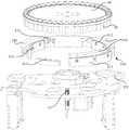
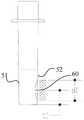
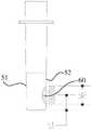
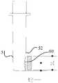
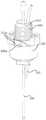
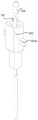
参阅图1,图12和图14,一种清洗装置,用于清洗反应杯50中的磁珠复合物60,该清洗装置包括转盘40、主清洗机构20、副清洗机构30和磁珠复合物吸附机构10。转盘40、主清洗机构20和副清洗机构30均安装在磁珠复合物吸附机构10上。多个反应杯50均匀间隔的承载在转盘40的外周上,当转盘40转动时,反应杯50绕转盘40的中心轴线做公转运动,在磁珠复合物吸附机构10的作用下,磁珠复合物60多次交替吸附在反应杯50上相对设置的第一内侧面51和第二内侧面52上,主清洗机构20可以注入清洗液,清洗液将对在第一内侧面51和第二内侧面52之间来回泳动的磁珠复合物60进行清洗,当然,以一定速度注入的清洗液同样将对磁珠复合物60进行清洗。Referring to FIG. 1, FIG. 12 and FIG. 14, a cleaning device is used for cleaning themagnetic bead compound 60 in thecuvette 50. The cleaning device includes aturntable 40, amain cleaning mechanism 20, asecondary cleaning mechanism 30 and a magnetic bead compound.Adsorption mechanism 10 . Theturntable 40 , themain cleaning mechanism 20 and theauxiliary cleaning mechanism 30 are all mounted on the magnetic beadcomplex adsorption mechanism 10 . A plurality of reaction cups 50 are evenly spaced on the outer circumference of theturntable 40. When theturntable 40 rotates, the reaction cups 50 revolve around the central axis of theturntable 40. Under the action of the magnetic beadcomposite adsorption mechanism 10, the magnetic beads composite Thematerial 60 is alternately adsorbed on the firstinner side 51 and the secondinner side 52 of thecuvette 50. Themain cleaning mechanism 20 can inject cleaning liquid, and the cleaning liquid will be on the firstinner side 51 and the secondinner side 52. Themagnetic bead complex 60 swimming back and forth between the side surfaces 52 is cleaned. Of course, the cleaning solution injected at a certain speed will also clean themagnetic bead complex 60 .

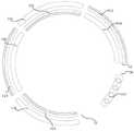
同时参阅图1至图4,在一些实施例中,磁珠复合物吸附机构10包括底座12和多个侧吸组件11。底座12上设置有输入工位14和主输出工位15,反应杯50从输入工位14进入磁珠复合物吸附机构10,绕中心轴线公转一定角度后从主输出工位15输送至测量室进行下一步检测。沿反应杯50的公转方向,多个侧吸组件11环绕转盘40的中心轴线设置,并位于输入工位14与主输出工位15之间,多个侧吸组件11交替设置于反应杯50的公转轨迹的内侧和外侧,相邻两个侧吸组件11沿转盘40的径向相互间隔一定的距离(换句话说,相邻两个侧吸组件11与反应杯公转中心轴线的径向距离不同),以形成供反应杯50运行的通道,多个侧吸组件11的磁吸面朝向反应杯50的公转轨迹。相邻两个侧吸组件11沿反应杯50的公转轨迹的周向相互间隔一定的距离。当反应杯50公转时,多个侧吸组件11使得磁珠复合物60交替吸附在反应杯50的第一内侧面51和第二内侧面52上。Referring to FIGS. 1 to 4 at the same time, in some embodiments, the magnetic beadcomplex adsorption mechanism 10 includes a base 12 and a plurality of side suction components 11 . The base 12 is provided with aninput station 14 and amain output station 15. Thecuvette 50 enters the magnetic beadcomposite adsorption mechanism 10 from theinput station 14, and is transported from themain output station 15 to the measurement chamber after revolving around the central axis at a certain angle. Proceed to the next test. Along the revolution direction of thecuvette 50 , a plurality of side suction assemblies 11 are arranged around the central axis of theturntable 40 and are located between theinput station 14 and themain output station 15 , and the plurality of side suction assemblies 11 are alternately arranged on thecuvette 50 . On the inside and outside of the revolution track, two adjacent side suction assemblies 11 are spaced a certain distance from each other along the radial direction of the turntable 40 (in other words, the radial distance between the two adjacent side suction assemblies 11 and the revolving center axis of the cuvette is different. ) to form a channel for thecuvette 50 to run, and the magnetic attraction surfaces of the plurality of side suction assemblies 11 face the revolution track of thecuvette 50 . Two adjacent side suction assemblies 11 are spaced apart from each other by a certain distance along the circumferential direction of the revolution track of thecuvette 50 . When thecuvette 50 revolves, the plurality of side suction components 11 make themagnetic bead composites 60 alternately adsorb on the firstinner side 51 and the secondinner side 52 of thecuvette 50 .

参阅图1和图2,在其它实施例中,磁珠复合物吸附机构10包括底座12、底吸组件115和多个侧吸组件11。底座12上设置有输入工位14、主输出工位15和副输出工位16,副输出工位16处于输入工位14与主输出工位15之间。沿反应杯50的公转方向,多个侧吸组件11环绕转盘40的中心轴线设置,并位于输入工位14与主输出工位15之间,相邻两个侧吸组件11沿转盘40的径向相互间隔一定的距离,以形成供反应杯50运行的通道。沿反应杯50的公转方向,底吸组件115位于主输出工位15和副输出工位16之间。反应杯50从输入工位14进入磁珠复合物吸附机构10后,有三种运动模式:①反应杯50绕中心轴线公转(小于一周)并第一次抵达主输出工位15,并从主输出工位15输出至测量室进行下一步检测;②反应杯50绕中心轴线公转(小于一周),经主输出工位15并第一次抵达副输出工位16,并从副输出工位16输出至反应盘以进行第二次加样;③反应杯50绕中心轴线公转若干周,最后从主输出工位15输出至测量室。Referring to FIGS. 1 and 2 , in other embodiments, the magnetic beadcomplex adsorption mechanism 10 includes a base 12 , abottom suction component 115 and a plurality of side suction components 11 . The base 12 is provided with aninput station 14 , amain output station 15 and anauxiliary output station 16 , and theauxiliary output station 16 is located between theinput station 14 and themain output station 15 . Along the revolution direction of thecuvette 50 , a plurality of side suction assemblies 11 are arranged around the central axis of theturntable 40 and are located between theinput station 14 and themain output station 15 , and two adjacent side suction assemblies 11 are along the diameter of theturntable 40 . They are spaced a certain distance from each other to form a channel for thecuvette 50 to run. Along the revolution direction of thecuvette 50 , thebottom suction assembly 115 is located between themain output station 15 and theauxiliary output station 16 . After thecuvette 50 enters the magnetic beadcomplex adsorption mechanism 10 from theinput station 14, there are three motion modes: (1) thecuvette 50 revolves around the central axis (less than one circle) and reaches themain output station 15 for the first time, and outputs from themain output station 15. Thestation 15 is output to the measuring room for the next step of detection; ② thereaction cup 50 revolves around the central axis (less than one cycle), passes through themain output station 15 and arrives at theauxiliary output station 16 for the first time, and is output from theauxiliary output station 16 to the reaction plate for the second sample addition; ③ thereaction cup 50 revolves around the central axis for several times, and finally is output from themain output station 15 to the measurement chamber.

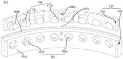
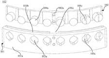
参阅图2至图4,多个侧吸组件11沿反应杯50公转方向依次首尾相对设置(即依次交错排列在一段优弧的两侧),侧吸组件11包括安装体105和若干磁性体104,安装体105大致呈圆弧状,安装体105上设置有圆弧形安装面101a(为竖直面),圆弧形安装面101a的轴线与转盘40的中心轴线重合,圆弧形安装面101a上安装有若干磁性体104,该磁性体104用于对反应杯50中的磁珠复合物60产生吸附力。沿反应杯50公转方向,对于从输入工位14依次排列至主输出工位15之间的任意相邻两个侧吸组件11,该两个侧吸组件11的圆弧形安装面101a分别位于反应杯运动轨迹54的异侧,并且两个圆弧形安装面101a相对中心轴线的朝向相反。换言之,一个圆弧形安装面101a(凹面)位于反应杯50转动轨迹的外侧并面对中心轴线,另一圆弧形安装面101a(凸面)则位于反应杯50转动轨迹的内侧并背向中心轴线。Referring to FIGS. 2 to 4 , a plurality of side suction assemblies 11 are arranged in turn opposite to each other along the revolution direction of the cuvette 50 (that is, they are arranged staggered on both sides of a segment of the arc), and the side suction assemblies 11 include a mountingbody 105 and a plurality ofmagnetic bodies 104 , the mountingbody 105 is roughly arc-shaped, and the mountingbody 105 is provided with an arc-shapedmounting surface 101a (which is a vertical surface), the axis of the arc-shapedmounting surface 101a coincides with the central axis of theturntable 40, and the arc-shaped mounting surface A plurality ofmagnetic bodies 104 are installed on the 101a, and themagnetic bodies 104 are used to generate adsorption force on themagnetic bead composite 60 in thecuvette 50 . Along the revolving direction of thecuvette 50, for any two adjacent side suction assemblies 11 arranged in sequence from theinput station 14 to themain output station 15, the arc-shaped mounting surfaces 101a of the two side suction assemblies 11 are located at Thecuvette motion track 54 is on the opposite side, and the two arc-shapedmounting surfaces 101a are oriented opposite to the central axis. In other words, one arc-shapedmounting surface 101a (concave surface) is located outside the rotation track of thecuvette 50 and faces the central axis, and the other arc-shapedmounting surface 101a (convex surface) is located inside the rotation track of thecuvette 50 and faces away from the center axis.

参阅图2至图4,侧吸组件11的数量为四个,当然,根据实际情况需要,侧吸组件11的数量可以做适当增减,例如三个或五个等。四个侧吸组件11包括第一侧吸组件111、第二侧吸组件112、第三侧吸组件113和第四侧吸组件114,四者沿反应杯50公转方向依次排列。以反应杯50公转方向(逆时针)为参考,第一侧吸组件111与输入工位14对应的一端为首端,其另一端为尾端,依次类推,第二侧吸组件112与第一侧吸组件111尾端对应的一端为首端,其另一端为尾端,第四侧吸组件114的尾端与主输出工位15对应。第一侧吸组件111位于反应杯运动轨迹54的外侧,即第一侧吸组件111上的圆弧形安装面101a为凹面,并面向中心轴线。根据相邻两个侧吸组件11的排布规律,第二侧吸组件112的圆弧形安装面101a(凸面)背向中心轴线,第三侧吸组件113的圆弧形安装面101a(凹面)面向中心轴线,第四侧吸组件114的圆弧形安装面101a(凸面)背向中心轴线。2 to 4 , the number of side suction components 11 is four. Of course, the number of side suction components 11 can be appropriately increased or decreased according to actual needs, such as three or five. The four side suction assemblies 11 include a firstside suction assembly 111 , a secondside suction assembly 112 , a thirdside suction assembly 113 and a fourthside suction assembly 114 , which are arranged in sequence along the revolution direction of thecuvette 50 . Taking the revolution direction (counterclockwise) of thecuvette 50 as a reference, the end of the firstside suction assembly 111 corresponding to theinput station 14 is the head end, the other end is the tail end, and so on, the secondside suction assembly 112 and the first side One end corresponding to the tail end of thesuction assembly 111 is the head end, the other end is the tail end, and the tail end of the fourthside suction assembly 114 corresponds to themain output station 15 . The firstside suction assembly 111 is located outside thecuvette movement track 54, that is, the arc-shapedmounting surface 101a on the firstside suction assembly 111 is concave and faces the central axis. According to the arrangement of two adjacent side suction assemblies 11, the arc-shapedmounting surface 101a (convex surface) of the secondside suction assembly 112 faces away from the central axis, and the arc-shapedmounting surface 101a (concave surface) of the third side suction assembly 113 ) faces the central axis, and the arc-shapedmounting surface 101a (convex surface) of the fourthside suction assembly 114 faces away from the central axis.

参阅图2、图5、图10和图21,对于设置有底吸组件115的磁珠复合物吸附机构10,底吸组件115的数量为一个,侧吸组件11的数量同样为四个,底吸组件115的首端与第四侧吸组件114的尾端相对,底吸组件115的尾端与副输出工位16对应,底吸组件115同样可以包括安装体105和磁性体104,磁性体104安装在安装体105的圆弧形安装面101a(为水平面)上。因此,侧吸组件11的圆弧形安装面101a(竖直面)环绕反应杯50的侧壁,可以将磁珠复合物60吸附在反应杯50的第一内侧面51或者第二内侧面52上;底吸组件115的圆弧形安装面101a(水平面)位于反应杯50的底壁的正下方,可以将磁珠复合物60吸附在反应杯50的底面53上。Referring to FIGS. 2 , 5 , 10 and 21 , for the magnetic beadcomposite adsorption mechanism 10 provided with thebottom suction assembly 115 , the number ofbottom suction assemblies 115 is one, the number of side suction assemblies 11 is also four, and the number of bottom suction assemblies 11 is also four. The head end of thesuction assembly 115 is opposite to the tail end of the fourthside suction assembly 114, and the tail end of thebottom suction assembly 115 corresponds to theauxiliary output station 16. Thebottom suction assembly 115 can also include a mountingbody 105 and amagnetic body 104. Themagnetic body 104 is mounted on the arc-shapedmounting surface 101a (which is a horizontal surface) of the mountingbody 105 . Therefore, the arc-shaped mountingsurface 101 a (vertical surface) of the side suction assembly 11 surrounds the side wall of thecuvette 50 , and themagnetic bead composite 60 can be adsorbed on the firstinner side 51 or the secondinner side 52 of thecuvette 50 . The arc-shapedmounting surface 101a (horizontal plane) of thebottom suction component 115 is located just below the bottom wall of thecuvette 50, and themagnetic bead composite 60 can be adsorbed on thebottom surface 53 of thecuvette 50.

第一侧吸组件111与第三侧吸组件113上的圆弧形安装面101a到中心轴线的距离相等,第二侧吸组件112与第四侧吸组件114上的圆弧形安装面101a到中心轴线的距离相等。The distances from the arc-shapedmounting surfaces 101a on the first side-suction assembly 111 and the third side-suction assembly 113 to the central axis are equal, and the arc-shapedmounting surfaces 101a on the second side-suction assembly 112 and the fourth side-suction assembly 114 The distance from the center axis is equal.

参阅图5,安装体105包括固定座101和插装板102,固定座101的顶壁上开设有第一安装槽101b,第一安装槽101b沿圆弧形安装面101a的周向延伸,即第一安装槽101b的内侧面与圆弧形安装面101a平行设置。圆弧形安装面101a开设有若干安装孔103,该安装孔103与第一安装槽101b连通,当然,安装孔103的中心线可以垂直圆弧形安装面101a。插装板102与第一安装槽101b配合,即插装板102插置在第一安装槽101b中,磁性体104容置在安装孔103中,磁性体104的一端与插装板102的侧壁连接。Referring to FIG. 5 , the mountingbody 105 includes a fixingbase 101 and an insertingboard 102 . The top wall of the fixingbase 101 is provided with a first mountinggroove 101 b , and the first mountinggroove 101 b extends along the circumferential direction of the arc-shaped mountingsurface 101 a The inner surface of thefirst installation groove 101b is arranged in parallel with the arc-shapedinstallation surface 101a. The arc-shapedmounting surface 101a is provided with a plurality of mountingholes 103, and the mountingholes 103 communicate with the first mountinggroove 101b. Of course, the centerline of the mountinghole 103 may be perpendicular to the arc-shapedmounting surface 101a. Theinsertion board 102 is matched with thefirst installation slot 101b, that is, theinsertion board 102 is inserted in thefirst installation slot 101b, themagnetic body 104 is accommodated in theinstallation hole 103, and one end of themagnetic body 104 is connected to the side of theinsertion board 102. wall connection.

参阅图5至图7,固定座101上还可以开设第二安装槽101c,第二安装槽101c设置在固定座101上与圆弧形安装面101a相对的侧面上,第二安装槽101c沿圆弧形安装面101a的轴向延伸(竖直设置),第二安装槽101c与第一安装槽101b连通。例如,沿固定座101的周向,第二安装槽101c到固定座101的两端的距离相等,即第二安装槽101c位于固定座101的正中间,当然,第二安装槽101c也可以偏离固定座101的正中间位置。插装板102的侧壁上设置有竖直的限位凸条102a,限位凸条102a与第二安装槽101c配合。当插装板102安装在固定座101上时,通过螺栓将限位凸条102a固定在固定座101上。Referring to FIGS. 5 to 7 , asecond installation groove 101c may also be formed on the fixingbase 101 . Thesecond installation groove 101c is disposed on the side of the fixingbase 101 opposite to the arc-shapedinstallation surface 101a , and thesecond installation groove 101c is along the circular arc. The axial extension of the arc-shapedmounting surface 101a (arranged vertically), the second mountinggroove 101c communicates with the first mountinggroove 101b. For example, along the circumferential direction of the fixedseat 101, the distances from thesecond installation groove 101c to both ends of the fixedseat 101 are equal, that is, thesecond installation groove 101c is located in the middle of the fixedseat 101. Of course, thesecond installation groove 101c can also be offset from the fixed seat The center position of theseat 101. A vertical limiting protrudingstrip 102a is disposed on the side wall of the plug-inboard 102, and the limiting protrudingstrip 102a is matched with thesecond installation groove 101c. When the plug-inboard 102 is installed on the fixingbase 101 , the limiting protrudingstrips 102 a are fixed on the fixingbase 101 by bolts.

侧吸组件11安装时,首先,将插装板102放置在第一安装槽101b中,并使限位凸条102a与第二安装槽101c配合,然后,将磁性体104放入安装孔103中,并使磁性体104的端部吸附在插装板102上,同时,将限位凸条102a与固定座101螺栓连接。最后,在安装孔103注入胶水,使磁性体104与固定座101和插装板102连接固定。When installing the side suction assembly 11 , first, place the plug-inboard 102 in thefirst installation groove 101 b , and make the limiting protrudingstrip 102 a fit with thesecond installation groove 101 c , and then put themagnetic body 104 into theinstallation hole 103 , and the end of themagnetic body 104 is adsorbed on theinsertion board 102 , and at the same time, the limiting protrudingstrip 102 a is bolted to the fixingseat 101 . Finally, glue is injected into the mountinghole 103 to connect and fix themagnetic body 104 with the fixingbase 101 and theinsertion board 102 .

安装孔103的截面形状可以为圆周形(中心角为360°)、半圆弧形(中心角为180°)或优弧形(中心角为位于180°与360°之间),即安装孔103可以为圆孔、半圆孔或优弧孔。安装孔103包括若干对第一通孔103a和若干对第三通孔103c,第一通孔103a与反应杯50的转入方向对应(即靠近侧吸组件11的首端),第三通孔103c与反应杯50的转出方向对应(即靠近侧吸组件11的尾端)。磁性体104包括第一磁铁104a和第三磁铁104c,第一磁铁104a位于第一通孔103a中,第三磁铁104c位于第三通孔103c中。其中,任意一对第一通孔103a中的两个第一磁铁104a之间的磁吸面积(对应磁场的有效辐射范围)为D1,任意一对第三通孔103c中的两个第三磁铁104c之间的磁吸面积(对应磁场的有效辐射范围)为D3,D1>D3。因此,当反应杯50对应从每一个侧吸组件11的首端公转至尾端时,由于D1>D3,磁吸面积的减少且磁铁磁力足够,使得磁珠复合物60聚集的更加紧密(磁珠复合物60的总量保持不变),进而使磁珠复合物60在反应杯50上的吸附面积减少,同时,反应杯50运动至对应侧吸组件11的尾端时,必须对其进行抽废液处理,由于磁珠复合物60吸附面积的减少,磁珠复合物60在反应杯50上更加紧密聚集,可以避免磁珠复合物60跟随废液被抽走,防止磁珠复合物60损失。The cross-sectional shape of the mountinghole 103 can be circular (central angle is 360°), semi-circular arc (central angle is 180°) or excellent arc (central angle is between 180° and 360°), that is, the mountinghole 103 It can be round hole, semi-circle hole or excellent arc hole. The mountinghole 103 includes a plurality of pairs of first throughholes 103a and a plurality of pairs of third throughholes 103c. The first throughholes 103a correspond to the rotation direction of the cuvette 50 (ie, close to the head end of the side suction assembly 11). The third throughholes 103c corresponds to the turning-out direction of the cuvette 50 (ie, close to the rear end of the side suction assembly 11). Themagnetic body 104 includes afirst magnet 104a and athird magnet 104c, thefirst magnet 104a is located in the first throughhole 103a, and thethird magnet 104c is located in the third throughhole 103c. Wherein, the magnetic attraction area (corresponding to the effective radiation range of the magnetic field) between the twofirst magnets 104a in any pair of first throughholes 103a is D1 , and the two third throughholes 103c in any pair of third throughholes 103c The magnetic attraction area between themagnets 104c (corresponding to the effective radiation range of the magnetic field) is D3 , and D1 > D3 . Therefore, when thecuvette 50 revolves correspondingly from the head end to the tail end of each side suction component 11 , since D1 > D3 , the magnetic suction area is reduced and the magnetic force of the magnet is sufficient, so that themagnetic bead composites 60 gather more closely (The total amount of themagnetic bead compound 60 remains unchanged), thereby reducing the adsorption area of themagnetic bead compound 60 on thecuvette 50. At the same time, when thecuvette 50 moves to the end of the corresponding side suction component 11, it must It performs waste liquid extraction treatment. Due to the reduction of the adsorption area of themagnetic bead compound 60, themagnetic bead compound 60 is more closely aggregated on thecuvette 50, which can prevent themagnetic bead compound 60 from being sucked away with the waste liquid, preventing themagnetic bead compound 60 from being drawn away. 60 losses.

安装孔103还可以包括若干对第二通孔103b,第二通孔103b位于第一通孔103a和第三通孔103c之间,磁性体104还包括第二磁铁104b,第二磁铁104b安装在第二通孔103b中。其中,任意一对第二通孔103b中的两个第二磁铁104b之间的磁吸面积为D2,D1>D2>D3The mountinghole 103 may further include a plurality of pairs of second throughholes 103b, the second throughholes 103b are located between the first throughhole 103a and the third throughhole 103c, and themagnetic body 104 further includes asecond magnet 104b, and thesecond magnet 104b is mounted on the in the second throughhole 103b. The magnetic attraction area between the twosecond magnets 104b in any pair of the second throughholes 103b is D2 , and D1 > D2 > D3 .

同一侧吸组件11上的若干安装孔103到底座12的距离相等,也可以不相等。不同侧吸组件11上的若干安装孔103相对底座12的距离不相等,也可以相等。对于同一侧吸组件11,沿其首端至尾端,安装孔103相对底座12的距离逐渐减小时,磁性体104相对底座12的距离减小,当反应杯50对应首端公转至尾端时,磁珠复合物60在反应杯50上的吸附位置越靠近反应杯50的底面53,实现磁珠复合物60吸附位置下拉的效果。The distances from the mountingholes 103 on the same side suction assembly 11 to the base 12 are equal or may not be equal. The distances between the mountingholes 103 on the different side suction assemblies 11 relative to the base 12 are not equal, and may also be equal. For the same side suction assembly 11, along the head end to the tail end, when the distance between the mountinghole 103 and the base 12 gradually decreases, the distance between themagnetic body 104 and the base 12 decreases, and when thecuvette 50 revolves from the head end to the tail end , the adsorption position of themagnetic bead composite 60 on thecuvette 50 is closer to thebottom surface 53 of thecuvette 50 , so that the effect of pulling down the adsorption position of themagnetic bead composite 60 is realized.

在一实施例(实施例1)中,参阅图5,图11至图13,例如:第一侧吸组件111上设置有三对第一通孔103a和两对第三通孔103c,第一通孔103a为圆孔,第三通孔103c为半圆孔,对应的,第一磁铁104a为圆柱形,第三磁铁104c为半圆柱形。圆孔与半圆孔的半径相等,一对第一通孔103a之间的间距大于一对半圆孔之间的间距,因此,一对第一磁铁104a之间的磁吸面积大于一对第三磁铁104c之间的磁吸面积。第一通孔103a和第三通孔103c到底座12的距离均相等(即在圆弧形安装面101a上的高度相等)。因此,当反应杯50对应从第一侧吸组件111的首端公转至尾端时,磁珠复合物60在反应杯50上对应的磁性体104的有效高度d1(对应磁吸面积D1)减少至d2(对应磁吸面积D3),即由分散聚拢(对应第一聚拢状态)变为半紧密聚拢(对应第二聚拢状态);同时,磁珠复合物60在反应杯50上的吸附位置的中心(对应磁性体中心高度t1)相对其底面53的距离保持不变。In an embodiment (Embodiment 1), referring to FIG. 5, FIG. 11 to FIG. 13, for example: the firstside suction component 111 is provided with three pairs of first throughholes 103a and two pairs of third throughholes 103c. Thehole 103a is a circular hole, and the third throughhole 103c is a semi-circular hole. Correspondingly, thefirst magnet 104a is a cylindrical shape, and thethird magnet 104c is a semi-cylindrical shape. The radius of the circular hole and the semicircular hole are equal, and the distance between the pair of first throughholes 103a is greater than the distance between the pair of semicircular holes. Therefore, the magnetic attraction area between the pair offirst magnets 104a is larger than that between the pair of third magnets Magnetic area between 104c. The distances from the first throughhole 103a and the third throughhole 103c to the base 12 are the same (ie, the heights on the arc-shapedmounting surface 101a are the same). Therefore, when thecuvette 50 revolves from the head end to the tail end of the firstside attraction component 111, the effective height d1 of themagnetic body 104 corresponding to themagnetic bead composite 60 on the cuvette 50 (corresponding to the magnetic attraction area D1 ) is reduced to d2 (corresponding to the magnetic attraction area D3 ), that is, from dispersed aggregation (corresponding to the first aggregation state) to semi-tight aggregation (corresponding to the second aggregation state); at the same time, themagnetic bead complex 60 is on thecuvette 50 The distance between the center of the adsorption position (corresponding to the height t1 of the magnetic body center) relative to itsbottom surface 53 remains unchanged.

参阅图6,图14和图15,第二侧吸组件112的结构与第一侧吸组件111的结构大致相同,第二侧吸组件112上安装孔103相对底座12的距离等于第一侧吸组件111中安装孔103相对底座12的距离,第二侧吸组件112同样设置有三对圆形的第一通孔103a和两对半圆形的第三通孔103c。圆孔与半圆孔的半径相等,一对第一通孔103a之间的间距大于一对半圆孔之间的间距,当反应杯50对应从第二侧吸组件112的首端公转至尾端时,磁珠复合物60在反应杯50上的有效高度d1(对应磁吸面积D1)减少至d2(对应磁吸面积D3),即由分散聚拢(对应第一聚拢状态)变为半紧密聚拢(对应第二聚拢状态);同时,磁珠复合物60在反应杯50上的吸附位置的中心(对应磁性体中心高度t1)相对其底面53的距离保持不变。6, 14 and 15, the structure of the secondside suction assembly 112 is substantially the same as that of the firstside suction assembly 111, and the distance between the mountinghole 103 on the secondside suction assembly 112 and the base 12 is equal to that of the first side suction assembly The distance between the mountinghole 103 in theassembly 111 and the base 12, the secondside suction assembly 112 is also provided with three pairs of circular first throughholes 103a and two pairs of semicircular third throughholes 103c. The radius of the circular hole and the semicircular hole are equal, and the distance between the pair of first throughholes 103a is greater than the distance between the pair of semicircular holes. , the effective height d1 (corresponding to the magnetic attraction area D1 ) of themagnetic bead complex 60 on thecuvette 50 is reduced to d2 (corresponding to the magnetic attraction area D3 ), that is, from dispersion and aggregation (corresponding to the first aggregation state) to At the same time, the distance between the center of the adsorption position of themagnetic bead composite 60 on the cuvette 50 (corresponding to the center height t1 of the magnetic body) relative to itsbottom surface 53 remains unchanged.

参阅图7和图8,图16和图17,第三侧吸组件113上第一通孔103a相对底座12的距离等于第二侧吸组件112中安装孔103相对底座12的距离,同时,从第三侧吸组件113的首端至尾端,安装孔103相对底座12的距离逐渐降低。第三侧吸组件113上设置有三对圆形的第一通孔103a和两对半圆形的第三通孔103c,圆孔与半圆孔的半径相等,一对第一通孔103a之间的间距大于一对半圆孔之间的间距,当反应杯50对应从第三侧吸组件113的首端公转至尾端时,磁珠复合物60在反应杯50上对应的磁性体104的有效高度d1(对应磁吸面积D1)减少至d2(对应磁吸面积D3),即由分散聚拢(对应第一聚拢状态)变为半紧密聚拢(对应第二聚拢状态);同时,磁性体中心高度t1减少至t2,磁性体104所产生磁性力的作用位置相对底面53的距离减少,因此,磁珠复合物60在反应杯50上的吸附位置的中心相对其底面53的距离同样减少,即将磁珠复合物60相对底面53往下拉近一定的距离。7, 8, 16 and 17, the distance between the first throughhole 103a on the thirdside suction assembly 113 and the base 12 is equal to the distance between the mountinghole 103 in the secondside suction assembly 112 and the base 12. At the same time, from From the head end to the tail end of the thirdside suction assembly 113 , the distance between the mountinghole 103 and the base 12 gradually decreases. The thirdside suction assembly 113 is provided with three pairs of circular first throughholes 103a and two pairs of semicircular third throughholes 103c. The round holes and the semicircular holes have equal radii. The spacing is greater than the spacing between a pair of semicircular holes. When thecuvette 50 revolves from the head end to the tail end of the thirdside suction component 113 , the effective height of themagnetic body 104 corresponding to themagnetic bead composite 60 on thecuvette 50 corresponds to d1 (corresponding to the magnetic attraction area D1 ) is reduced to d2 (corresponding to the magnetic attraction area D3 ), that is, it changes from dispersed gathering (corresponding to the first gathering state) to semi-tight gathering (corresponding to the second gathering state); at the same time, the magnetic When the height t1 of the center of the body decreases to t2 , the distance between the action position of the magnetic force generated by themagnetic body 104 and thebottom surface 53 decreases. Therefore, the distance between the center of the adsorption position of themagnetic bead composite 60 on thecuvette 50 relative to thebottom surface 53 The same is reduced, that is, themagnetic bead composite 60 is pulled down by a certain distance relative to thebottom surface 53 .

参阅图9,图18至图20,第四侧吸组件114上安装孔103相对底座12的距离等于第三侧吸组件113中安装孔103相对底座12的最小距离,同时,各安装孔103相对底座12的距离相等。第四侧吸组件114上设置有一对圆形的第一通孔103a、三对半圆形的第二通孔103b和三对优弧形的第三通孔103c。第一通孔103a与第二通孔103b的半径相等,第三通孔103c的半径小于第二通孔103b的半径,第一通孔103a的横截面面积最大,第二通孔103b的横截面面积次之,第三通孔103c的横截面面积最小;同时,磁性体104均为与安装孔103相适配的条形磁铁,第一磁铁104a的体积最大,第二磁铁104b的体积次之,第三磁铁104c的体积最小。因此,位于第一通孔103a中的两个第一磁铁104a的磁吸面积最大(为D1),位于第二通孔103b中的两个第二磁铁104b的磁吸面积次之(为D2),位于第三通孔103c中的两个第三磁铁104c的磁吸面积最小(为D3)。当反应杯50对应从第四侧吸组件114的首端公转至尾端时,磁珠复合物60在反应杯50上对应的磁性体104的有效高度d1(对应磁吸面积D1)减少至d2(对应磁吸面积D2)、最后减少至d3(对应磁吸面积D3),即首先由分散聚拢(对应第一聚拢状态)变为半紧密聚拢(对应第二聚拢状态),最后有半紧密聚拢(对应第二聚拢状态)变为全紧密聚拢(对应第三聚拢状态);同时,磁珠复合物60在反应杯50上的吸附位置的中心(对应磁性体中心高度t2)相对其底面53的距离保持不变。9, 18 to 20, the distance between the mountingholes 103 on the fourthside suction assembly 114 and the base 12 is equal to the minimum distance between the mountingholes 103 in the thirdside suction assembly 113 and the base 12, and at the same time, the mountingholes 103 are opposite to each other. The distances between the bases 12 are equal. The fourthside suction component 114 is provided with a pair of circular first throughholes 103a, three pairs of semicircular second throughholes 103b and three pairs of curved third throughholes 103c. The radius of the first throughhole 103a and the second throughhole 103b are equal, the radius of the third throughhole 103c is smaller than that of the second throughhole 103b, the cross-sectional area of the first throughhole 103a is the largest, and the cross-sectional area of the second throughhole 103b The area of the third throughhole 103c is the second, and the cross-sectional area of the third throughhole 103c is the smallest; at the same time, themagnetic bodies 104 are all bar magnets that match the mounting holes 103. The volume of thefirst magnet 104a is the largest, and the volume of thesecond magnet 104b is second. , the volume of thethird magnet 104c is the smallest. Therefore, the magnetic attraction area of the twofirst magnets 104a located in the first throughhole 103a is the largest (D1 ), and the magnetic attraction area of the twosecond magnets 104b located in the second throughhole 103b is second (D 1 ).2 ), the magnetic attraction area of the twothird magnets 104c located in the third throughhole 103c is the smallest (D3 ). When thecuvette 50 revolves correspondingly from the head end to the tail end of the fourthside attraction component 114 , the effective height d1 (corresponding to the magnetic attraction area D1 ) of themagnetic body 104 corresponding to themagnetic bead composite 60 on thecuvette 50 decreases to d2 (corresponding to the magnetic attraction area D2 ), and finally reduced to d3 (corresponding to the magnetic attraction area D3 ), that is, firstly from the dispersed gathering (corresponding to the first gathering state) to the semi-tight gathering (corresponding to the second gathering state) , and finally the semi-tight aggregation (corresponding to the second aggregation state) becomes fully compact aggregation (corresponding to the third aggregation state); at the same time, the center of the adsorption position of themagnetic bead complex 60 on the cuvette 50 (corresponding to the height t of the center of the magnetic body)2 ) The distance with respect to itsbottom surface 53 remains unchanged.

因此,对于上述实例1,在第一侧吸组件111中、第二侧吸组件112和第三侧吸组件113中,第一通孔103a(圆形)的数量均为三对,第三通孔103c(半圆形)的数量均为两对;在第四侧吸组件114中,第一通孔103a(圆形)的数量为一对,第二通孔103b(半圆形)的数量为三对,第三通孔103c(优弧形)的数量为三对。Therefore, for the above example 1, in the firstside suction assembly 111, the secondside suction assembly 112 and the thirdside suction assembly 113, the number of the first throughholes 103a (circular) are all three pairs, and the third The number ofholes 103c (semi-circular) is two pairs; in the fourthside suction component 114, the number of the first throughholes 103a (circular) is one pair, and the number of the second through-holes 103b (semi-circular) is one pair. is three pairs, and the number of the third throughholes 103c (preferably curved) is three pairs.

当然,还存在实施例2,对于该实施例,在第一侧吸组件111、第二侧吸组件112和第三侧吸组件113中,第一通孔103a(圆形)的数量均为三个,第二通孔103b(半圆形)的数量均为两对,第三通孔103c(优弧形)的数量均为三对。在第四侧吸组件114中,第一通孔103a(圆形)的数量为一对,第二通孔103b(半圆形)的数量为三对,第三通孔103c(优弧形)的数量均三对。第一通孔的半径最大,第二通孔103b的半径次之,第三通孔103c的半径最小Of course, there is alsoEmbodiment 2. For this embodiment, in the firstside suction assembly 111, the secondside suction assembly 112 and the thirdside suction assembly 113, the number of the first throughholes 103a (circular) is all three The number of the second throughholes 103b (semi-circular) is two pairs, and the number of the third throughholes 103c (excellent arc shape) is three pairs. In the fourthside suction assembly 114, the number of the first throughholes 103a (circular) is one pair, the number of the second throughholes 103b (semi-circular) is three pairs, and the third throughholes 103c (preferably curved) The quantity is three pairs. The radius of the first through hole is the largest, the radius of the second throughhole 103b is second, and the radius of the third throughhole 103c is the smallest

还存在实施例3,对于该实施例,在第一侧吸组件111中,第一通孔103a(圆形)的数量为一个,第二通孔103b(半圆形)的数量为一对,第三通孔103c(优弧形)的数量为六对;在第二侧吸组件112和第三侧吸组件113中,第二通孔103b(半圆形)的数量均为两对,第三通孔103c(优弧形)的数量均为六对,在第四侧吸组件114中,第一通孔103a(圆形)的数量为三个,第二通孔103b(半圆形)的数量为三对,第三通孔103c(优弧形)的数量为两对。第一通孔103a的半径最大,第二通孔103b的半径次之,第三通孔103c的半径最小。There is alsoEmbodiment 3. For this embodiment, in the firstside suction assembly 111, the number of the first throughholes 103a (circular) is one, and the number of the second throughholes 103b (semi-circular) is a pair, The number of the third throughholes 103c (preferably curved) is six pairs; in the secondside suction assembly 112 and the thirdside suction assembly 113, the number of the second throughholes 103b (semi-circular) is two pairs. The number of the three throughholes 103c (preferably curved) is six pairs. In the fourthside suction component 114, the number of the first throughholes 103a (circular) is three, and the number of the second throughholes 103b (semi-circular) is three. The number is three pairs, and the number of the third throughholes 103c (preferably curved) is two pairs. The radius of the first throughhole 103a is the largest, the radius of the second throughhole 103b is second, and the radius of the third throughhole 103c is the smallest.

为描述方便起见,实施1记为W1,实施例2记为W2,实施例3记为W3,当然,还存在另外五个实施例,分别记为W4,W5,W6,W7和W8。For the convenience of description,implementation 1 is denoted as W1,embodiment 2 is denoted as W2, andembodiment 3 is denoted as W3. Of course, there are five other embodiments, which are denoted as W4, W5, W6, W7 and W8 respectively.

在W4中,每个侧吸组件11上均设置四个第一通孔103a(圆形)和四对第三通孔103c(半圆形)。在W5中,每个侧吸组件11均设置四对第一通孔103a(半圆形)和四个第三通孔103c(圆形)。在W6中,每个侧吸组件11上均设置八个第一通孔103a(圆形)。在W7中,每个侧吸组件11上均设置八对第二通孔103b(半圆形),在W8中,每个侧吸组件11上均设置八对第三通孔103c(优弧形)。In W4, each side suction assembly 11 is provided with four first throughholes 103a (circular) and four pairs of third throughholes 103c (semi-circular). In W5, each side suction assembly 11 is provided with four pairs of first throughholes 103a (semi-circular) and four third through-holes 103c (circular). In W6, each side suction assembly 11 is provided with eight first throughholes 103a (circular). In W7, each side suction assembly 11 is provided with eight pairs of second throughholes 103b (semi-circular), and in W8, each side suction assembly 11 is provided with eight pairs of third throughholes 103c (preferably arcuate). ).

对于上述八个实施例,在后续磁珠复合物的清洗完毕后,分别从分析灵敏度(空白限)结果、测试准确度和非特异性吸附三个角度对其效果进行评估。For the above eight examples, after the subsequent cleaning of the magnetic bead complex, its effects were evaluated from three perspectives of analytical sensitivity (blank limit) results, test accuracy and non-specific adsorption.

1、对于分析灵敏度(空白限)结果检测:1. For the detection of analytical sensitivity (blank limit) results:

a)测试样本:美国Scantibodies公司的去激素的人血清(确定不含HBsAg、Anti-HCV、Anti-HIV I和Anti-HIV II)。a) Test sample: Dehormone human serum from Scantibodies, USA (determined to be free of HBsAg, Anti-HCV, Anti-HIV I and Anti-HIV II).

b)检测的试剂盒为新产业生物医学工程股份有限公司自制的HBsAg试剂盒,本试剂的阴性参考区间为<1.0index/mL,试剂盒检测范围为0-10000index/mL。b) The detection kit is the HBsAg kit made by New Industry Biomedical Engineering Co., Ltd. The negative reference interval of this reagent is <1.0 index/mL, and the detection range of the kit is 0-10000 index/mL.

c)新产业生物医学工程股份有限公司的HBsAg试剂盒检测具体包括以下步骤:c) The detection of HBsAg kit by New Industry Biomedical Engineering Co., Ltd. specifically includes the following steps:

1)一次加样:100μL测试样本、100μL缓冲液和20μL的磁性微球体系混合,温育20min,形成复合物;1) One-time sample addition: 100 μL of test sample, 100 μL of buffer and 20 μL of magnetic microsphere system were mixed, and incubated for 20 min to form a complex;

2)清洗:外加磁场将上述反应产物沉淀,去除上清液,并以缓冲液清洗;2) Cleaning: the above-mentioned reaction product is precipitated by an external magnetic field, the supernatant is removed, and washed with a buffer;

3)二次加样:将ABEI标记物体系加入上述沉淀中,混合均匀,温育20min。3) Secondary sample addition: Add the ABEI marker system to the above-mentioned precipitation, mix well, and incubate for 20 min.

4)检测:外加磁场将上述复合物沉淀,去除上清液,清洗后,加入发光底物,检测发出的相对光强度,计算得到HBsAg的含量。4) Detection: the above-mentioned complexes are precipitated by an external magnetic field, the supernatant is removed, and after washing, a luminescent substrate is added, and the relative light intensity emitted is detected, and the content of HBsAg is calculated.

发光信号强度采用全自动化学发光仪对测试样本进行测定。重复测定待测样本20次,并计算20次测量结果的平均值M和标准差SD,M+2SD的值即为分析灵敏度(空白限),(由于去激素人血清确认不含HBsAg,所以空白限越低,则分析灵敏度越高)。The intensity of the luminescent signal was measured by an automatic chemiluminescence instrument. Repeat the measurement of the sample to be tested 20 times, and calculate the mean value M and standard deviation SD of the 20 measurement results. The value of M+2SD is the analytical sensitivity (blank limit), (because the hormone-free human serum is confirmed to be free of HBsAg, so the blank The lower the limit, the higher the analytical sensitivity).

检测结果参阅下表1:The test results are shown in Table 1 below:

表1分析灵敏度(空白限)测定结果Table 1 Analysis Sensitivity (Blank Limit) Measurement Results

Figure BDA0001558895560000161

Figure BDA0001558895560000171

表1中数据的单位index/mL为公司产品自定义的单位,与WHO单位换算关系为1index/mL=0.1IU/mL。The unit index/mL of the data in Table 1 is the self-defined unit of the company's products, and the conversion relationship with the WHO unit is 1index/mL=0.1IU/mL.

由表1可以看出,W1对应的空白限计算结果为0.078index/mL,远小于其它实施例,且远低于试剂盒设定的截断值1.0index/mL,这是因为W1采用的扩散聚拢的清洗模式和内外交错式的结构实现往复搅拌混匀的作用,有效减少了非特异性的吸附,因此其分析灵敏度得到了显著提高。It can be seen from Table 1 that the calculated result of the blank limit corresponding to W1 is 0.078 index/mL, which is much smaller than that of other examples, and is much lower than the cut-off value of 1.0 index/mL set by the kit. This is because the diffusion aggregation adopted by W1 The cleaning mode and the internal and external staggered structure realize the effect of reciprocating stirring and mixing, which effectively reduces non-specific adsorption, so its analytical sensitivity has been significantly improved.

2、对于HBsAg国家参考品测定结果:2. For the determination results of HBsAg national reference materials:

a)测试样本:中国食品药品检定研究院制备的乙型肝炎病毒表面抗原(HBsAg)的国家参考品(300003-201002),其组成为:a) Test sample: National reference substance (300003-201002) of hepatitis B virus surface antigen (HBsAg) prepared by China National Institute for Food and Drug Control, which consists of:

1)阴性参考品20份,0.5mL/支。1) 20 negative reference products, 0.5mL/piece.

2)阳性参考品3份,0.5mL/支。2) 3 copies of positive reference products, 0.5mL/piece.

3)灵敏度参考品:9份,0.5mL/支。3) Sensitivity reference product: 9 copies, 0.5mL/piece.

adr亚型:adr-1(0.05IU/mL)、adr-2(0.1IU/mL)、adr-3(0.2IU/mL),各1支,0.5mL/支adr subtypes: adr-1 (0.05IU/mL), adr-2 (0.1IU/mL), adr-3 (0.2IU/mL), 1 each, 0.5mL/piece

adw亚型:adw-1(0.05IU/mL)、adw-2(0.1IU/mL)、adw-3(0.2IU/mL),各1支,0.5mL/支adw subtypes: adw-1 (0.05IU/mL), adw-2 (0.1IU/mL), adw-3 (0.2IU/mL), 1 each, 0.5mL/piece

ay亚型:ay-1(0.1IU/mL)、ay-2(0.2IU/mL)、ay-3(0.4IU/mL),各1支,0.5mL/支ay subtypes: ay-1 (0.1IU/mL), ay-2 (0.2IU/mL), ay-3 (0.4IU/mL), 1 each, 0.5mL/piece

b)新产业生物医学工程股份有限公司自制的HBsAg试剂盒,本试剂的阴性参考区间为<1.0index/mL,试剂盒检测范围为0-10000index/mL。b) The HBsAg kit made by New Industry Biomedical Engineering Co., Ltd. The negative reference interval of this reagent is <1.0 index/mL, and the detection range of the kit is 0-10000 index/mL.

c)新产业生物医学工程股份有限公司的HBsAg试剂盒检测具体包括以下步骤:c) The detection of HBsAg kit by New Industry Biomedical Engineering Co., Ltd. specifically includes the following steps:

1)一次加样:100μL测试样本、100μL缓冲液和20μL的磁性微球体系混合,温育20min,形成复合物;1) One-time sample addition: 100 μL of test sample, 100 μL of buffer and 20 μL of magnetic microsphere system were mixed, and incubated for 20 min to form a complex;

2)清洗:外加磁场将上述反应产物沉淀,去除上清液,并以缓冲液清洗;2) Cleaning: the above-mentioned reaction product is precipitated by an external magnetic field, the supernatant is removed, and washed with a buffer;

3)二次加样:将ABEI标记物体系加入上述沉淀中,混合均匀,温育20min。3) Secondary sample addition: Add the ABEI marker system to the above-mentioned precipitation, mix well, and incubate for 20 min.

4)检测:外加磁场将上述复合物沉淀,去除上清液,清洗后,加入发光底物,检测发出的相对光强度,计算得到HBsAg的含量。4) Detection: the above-mentioned complexes are precipitated by an external magnetic field, the supernatant is removed, and after washing, a luminescent substrate is added, and the relative light intensity emitted is detected, and the content of HBsAg is calculated.

发光信号强度采用全自动化学发光仪对测试样本进行测定,检测结果如表2所示。The luminescence signal intensity was measured by an automatic chemiluminescence instrument, and the detection results are shown in Table 2.

表2HBsAg国家参考品测定结果。Table 2 HBsAg national reference test results.

Figure BDA0001558895560000181

Figure BDA0001558895560000191

Figure BDA0001558895560000201

表2中数据单位为index/mL,为公司产品自定义的单位,与WHO单位换算关系为1index/mL=0.1IU/mLThe data unit in Table 2 is index/mL, which is a customized unit of the company's products, and the conversion relationship with the WHO unit is 1index/mL=0.1IU/mL

HBsAg国家参考品的检测标准为:阴性国家参考品(N1-N10)结果符合率达到20/20,阳性国家参考品(P1-P3)结果符合率达到3/3,adr亚型灵敏度参考品、adw亚型灵敏度参考品、ay亚型灵敏度参考品的最低检出限分别0.1IU/mL、0.1IU/mL、0.2IU/mL。The detection standards of HBsAg national reference products are: the coincidence rate of negative national reference products (N1-N10) results is 20/20, the coincidence rate of positive national reference products (P1-P3) results is 3/3, adr subtype sensitivity reference products, The minimum detection limits of the adw subtype sensitivity reference material and the ay subtype sensitivity reference material were 0.1IU/mL, 0.1IU/mL, and 0.2IU/mL, respectively.

结合表2,在W1至W7对应的结果中,阴性国家参考品符合率达到20/20,清洗站W8对应的阴性国家参考品符合率为19/20,因清洗效果的不同导致的非特意吸附使得W2~W8的表观HBsAg测定浓度略大于W1。清洗站W1~W8中3份阳性参考品的符合率均为3/3,且对高浓度阳性参考品不存在HOOK效应。清洗站W1中三种亚型参考品的灵敏度最低检出量分别为adr 0.1IU/mL、adw 0.05IU/mL、ay 0.1IU/mL,检测结果均达到国家标准,其对adw和ay的灵敏度甚至优于国家标准。由此可见,W1~W8通过不同的清洗方式使得对消除非特异吸附的影响程度不同,W1的准确度和灵敏度最优。Combined with Table 2, in the results corresponding to W1 to W7, the conformity rate of the negative country reference product reached 20/20, and the conformity rate of the negative country reference product corresponding to the cleaning station W8 was 19/20. Unintentional adsorption caused by different cleaning effects The apparent HBsAg measured concentrations of W2-W8 were slightly higher than that of W1. The coincidence rates of the three positive reference products in the cleaning stations W1-W8 were all 3/3, and there was no HOOK effect on the high-concentration positive reference products. The lowest sensitivity detection levels of the three subtype reference materials in the cleaning station W1 are adr 0.1IU/mL, adw 0.05IU/mL, ay 0.1IU/mL, and the detection results all meet the national standards, and their sensitivity to adw and ay Even better than the national standard. It can be seen that W1-W8 have different effects on eliminating non-specific adsorption through different cleaning methods, and W1 has the best accuracy and sensitivity.

3、对于临床样本HBsAg浓度测定结果:3. For the determination of HBsAg concentration in clinical samples:

a)测试样本:经过临床验证确认的阴性和阳性血各10例共20例。并分别采取这20个样本的血清和血浆进行测定HBsAg浓度测定。a) Test samples: 10 cases of negative and 10 positive blood confirmed by clinical verification, a total of 20 cases. The serum and plasma of these 20 samples were taken to determine the HBsAg concentration.

b)使用深圳市新产业生物医学工程股份有限公司提供乙肝表面抗原(HBsAg)测定试剂盒,本试剂的阴性参考区间为<1.0index/mL,试剂盒检测范围为0-10000index/mL。b) Use the Hepatitis B Surface Antigen (HBsAg) assay kit provided by Shenzhen New Industry Biomedical Engineering Co., Ltd. The negative reference interval of this reagent is <1.0index/mL, and the detection range of the kit is 0-10000index/mL.

c)新产业生物医学工程股份有限公司的HBsAg试剂盒检测具体包括以下步骤:c) The detection of HBsAg kit by New Industry Biomedical Engineering Co., Ltd. specifically includes the following steps:

1)一次加样:100μL测试样本、100μL缓冲液和20μL的磁性微球体系混合,温育20min,形成复合物;1) One-time sample addition: 100 μL of test sample, 100 μL of buffer and 20 μL of magnetic microsphere system were mixed, and incubated for 20 min to form a complex;

2)清洗:外加磁场将上述反应产物沉淀,去除上清液,并以缓冲液清洗;2) Cleaning: the above-mentioned reaction product is precipitated by an external magnetic field, the supernatant is removed, and washed with a buffer;

3)二次加样:将ABEI标记物体系加入上述沉淀中,混合均匀,温育20min。3) Secondary sample addition: Add the ABEI marker system to the above-mentioned precipitation, mix well, and incubate for 20 min.

4)检测:外加磁场将上述复合物沉淀,去除上清液,清洗后,加入发光底物,检测发出的相对光强度,计算得到HBsAg的含量。4) Detection: the above-mentioned complexes are precipitated by an external magnetic field, the supernatant is removed, and after washing, a luminescent substrate is added, and the relative light intensity emitted is detected, and the content of HBsAg is calculated.

发光信号强度采用全自动化学发光仪对测试样本进行测定,检测结果如表3所示。The luminescence signal intensity was measured by an automatic chemiluminescence instrument, and the detection results are shown in Table 3.

检测结果参阅下表3:The test results are shown in Table 3 below:

表3临床样本HBsAg浓度测定结果Table 3 Results of the determination of HBsAg concentration in clinical samples

Figure BDA0001558895560000211

Figure BDA0001558895560000221

表3中数据单位为index/mL。为公司产品自定义的单位,与WHO单位换算关系为1index/mL=0.1IU/mLThe unit of data in Table 3 is index/mL. The unit customized for the company's products, and the conversion relationship with the WHO unit is 1index/mL=0.1IU/mL

由表3可以看出:W2~W8对应的同一样本的血浆表观HBsAg浓度往往不同程度地大于血清中测定的浓度,这是由于于血浆当中的纤维蛋白等物质的干扰造成的,而W1因为采用了最优的扩散聚拢的清洗模式和内外交错式的结构方案实现往复搅拌混匀的作用,有效地改善了纤维蛋白絮状物对检测的干扰,使得W1中的血浆和血清测定的HBsAg浓度的一致性优于W2~W8的一致性。并且通过一致性的差异可以看出W8至W1呈现越来越优化的清洗效果。It can be seen from Table 3 that the plasma apparent HBsAg concentration of the same sample corresponding to W2 to W8 is often greater than the concentration measured in serum to varying degrees, which is caused by the interference of fibrin and other substances in the plasma, while W1 is due to the interference of fibrin and other substances in the plasma. The optimal cleaning mode of diffusion and gathering and the internal and external staggered structure scheme are adopted to realize the effect of reciprocating stirring and mixing, which effectively improves the interference of fibrin flocs on the detection, and makes the HBsAg concentration in plasma and serum determined in W1. The consistency is better than that of W2-W8. And through the difference in consistency, it can be seen that W8 to W1 present more and more optimized cleaning effects.

综上,W1的清洗效果最好,能有效降低非特异,提高试剂检测灵敏度和准确性。In conclusion, W1 has the best cleaning effect, which can effectively reduce non-specificity and improve the sensitivity and accuracy of reagent detection.

参阅图2和图3,磁珠复合物吸附机构10还可以包括多个圆弧形定位块116,圆弧形定位块116固定在底座12上,多个圆弧形定位块116沿反应杯50转动方向依次首尾相对设置,圆弧形定位块116与侧吸组件11相对反应杯50公转圆周的径向一一对应。相互对应的圆弧形定位块116与侧吸组件11分居反应杯运动轨迹54的异侧,两者围设成供反应杯50运行的通道。当反应杯50被公转时,圆弧形定位块116可以对反应杯50起到限位作用,防止其晃动,从而规范反应杯50的运动轨迹54,确保侧吸组件11对磁珠复合物60的吸附效果。圆弧形定位块116的端部可以与侧吸组件11连接为一体,也可以不连接。2 and 3 , the magnetic beadcomposite adsorption mechanism 10 may further include a plurality of arc-shaped positioning blocks 116 , the arc-shaped positioning blocks 116 are fixed on the base 12 , and the plurality of arc-shaped positioning blocks 116 are located along thecuvette 50 . The directions of rotation are arranged end to end in sequence, and the arc-shaped positioning blocks 116 are in one-to-one correspondence with the radial direction of the side suction assembly 11 relative to the revolving circumference of thecuvette 50 . The arc-shaped positioning blocks 116 corresponding to each other and the side suction assembly 11 are located on opposite sides of themovement track 54 of the cuvette, and they surround a channel for thecuvette 50 to run. When thecuvette 50 is revolved, the arc-shapedpositioning block 116 can limit thecuvette 50 to prevent it from shaking, so as to regulate themovement track 54 of thecuvette 50 and ensure that the side suction assembly 11 is effective against themagnetic bead composite 60 adsorption effect. The end of the arc-shapedpositioning block 116 may be integrally connected with the side suction assembly 11, or may not be connected.

参阅图1至图5,底座12包括垫板123、底板121和支撑柱122。底板121与垫板123相对设置,底板121位于垫板123的正上方,支撑柱122的上端与底板121连接,支撑柱122的下端与垫板123连接。侧吸组件11,底吸组件115和圆弧形定位块116均固定在底板121上。当然,底座12还可以包括检测光耦13,检测光耦13安装在底板121上,检测光耦13用于检测转盘40上是否有反应杯50(即空杯检测)。检测光耦13根据反射光强度确定是否有空杯现象,当反射光强度很低或几乎没有时,表明转盘40上出现空位,该位置处没有反应杯50,如果反射光强度较高,说明该位置处存在反应杯50。还可以根据主清洗机构20或副清洗机构30上的抽液针244来确定是否存在空杯现象,例如,如果抽液针244下行到一定位置时,抽液针244的电阻没有产生变化,说明该位置出现空杯,如果电阻有明显变化,则说明抽液针244已接触到反应杯50中的液体,说明此处存在反应杯50。Referring to FIGS. 1 to 5 , the base 12 includes a backing plate 123 , abottom plate 121 and a support column 122 . Thebottom plate 121 is opposite to the backing plate 123 , thebottom plate 121 is located directly above the backing plate 123 , the upper end of the support column 122 is connected with thebottom plate 121 , and the lower end of the supporting column 122 is connected with the backing plate 123 . The side suction assembly 11 , thebottom suction assembly 115 and the arc-shapedpositioning block 116 are all fixed on thebottom plate 121 . Of course, the base 12 may also include a detection optocoupler 13 , which is installed on thebottom plate 121 , and is used to detect whether there is acuvette 50 on the turntable 40 (ie, empty cuvette detection). The detection optical coupler 13 determines whether there is an empty cup phenomenon according to the reflected light intensity. When the reflected light intensity is very low or almost no, it indicates that there is a vacancy on theturntable 40, and there is nocuvette 50 at this position. If the reflected light intensity is high, it indicates that the There is acuvette 50 at the location. It can also be determined whether there is an empty cup phenomenon according to theliquid suction needle 244 on themain cleaning mechanism 20 or theauxiliary cleaning mechanism 30. For example, if theliquid suction needle 244 descends to a certain position, the resistance of theliquid suction needle 244 does not change. An empty cup appears at this position, and if the resistance changes significantly, it means that theliquid aspiration needle 244 has come into contact with the liquid in thecuvette 50, indicating that thecuvette 50 exists here.

转盘40与底座12上的底板121转动连接,主清洗机构20和副清洗机构30均固定安装在底座12上,转盘40位于磁珠复合物吸附机构10的正上方,反应杯50的下端与侧吸组件11和底吸组件115相对应。副清洗机构30与主输出工位15相邻,主清洗机构20环绕侧吸组件11设置、并位于输入工位14与主输出工位15之间。主清洗机构20与侧吸组件11的端部对应。Theturntable 40 is rotatably connected to thebottom plate 121 on the base 12 , themain cleaning mechanism 20 and theauxiliary cleaning mechanism 30 are fixedly installed on the base 12 , theturntable 40 is located directly above the magnetic beadcomplex adsorption mechanism 10 , the lower end of thereaction cup 50 and the side The suction assembly 11 corresponds to thebottom suction assembly 115 . Theauxiliary cleaning mechanism 30 is adjacent to themain output station 15 , and themain cleaning mechanism 20 is arranged around the side suction assembly 11 and is located between theinput station 14 and themain output station 15 . Themain cleaning mechanism 20 corresponds to the end of the side suction assembly 11 .

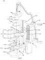
参阅图22,主清洗机构20包括第一安装架21、第一支撑架22、第一驱动组件23、管夹25和若干个主清洗组件24。第一安装架21固定在底座12上,第一支撑架22与第一安装架21滑动配合,第一驱动组件23与第一安装架21连接,第一驱动组件23驱动第一支撑架22上下滑动。管夹25可以为多个,管夹25安装在第一安装架21和第一支撑架22上、并用于支撑注液管71和抽液管72。主清洗组件24的数量可以为三个,三个主清洗组件24安装在第一支撑架22上。Referring to FIG. 22 , themain cleaning mechanism 20 includes a first mountingframe 21 , a first supportingframe 22 , afirst driving assembly 23 , apipe clamp 25 and severalmain cleaning assemblies 24 . Thefirst mounting frame 21 is fixed on the base 12 , the first supportingframe 22 is slidingly matched with the first mountingframe 21 , the first drivingassembly 23 is connected with the first mountingframe 21 , and the first drivingassembly 23 drives the first supportingframe 22 up and down slide. There may be a plurality of pipe clamps 25 . The pipe clamps 25 are mounted on the first mountingframe 21 and thefirst support frame 22 and are used to support theliquid injection pipe 71 and theliquid suction pipe 72 . The number of themain cleaning assemblies 24 may be three, and the threemain cleaning assemblies 24 are installed on thefirst support frame 22 .

参阅图22,第一安装架21可以包括支撑板211、滑座212和加强板213,支撑板211水平设置并固定在底座12上,滑座212竖直设置并与支撑板211连接,滑座212上开设有与第一支撑架22滑动配合的滑轨。加强板213连接在支撑板211与滑座212之间。Referring to FIG. 22 , the first mountingframe 21 may include asupport plate 211 , a slidingseat 212 and a reinforcingplate 213 , the supportingplate 211 is horizontally arranged and fixed on the base 12 , the slidingseat 212 is vertically arranged and connected with the supportingplate 211 , and the sliding seat The slide rail slidably matched with thefirst support frame 22 is provided on the 212 . The reinforcingplate 213 is connected between thesupport plate 211 and the slidingseat 212 .

第一支撑架22包括第一滑板221和第一固定板222。第一滑板221与第一安装架21上的滑座212滑动配合,第一固定板222与第一滑板221的顶端连接,第一固定板222水平设置并呈圆弧状,三个主清洗组件24间隔设置在第一固定板222上,每一个清洗组件24与侧吸组件11的尾端对应。Thefirst support frame 22 includes a first slidingplate 221 and afirst fixing plate 222 . The first slidingplate 221 is slidably matched with the slidingseat 212 on the first mountingframe 21, thefirst fixing plate 222 is connected with the top of the first slidingplate 221, thefirst fixing plate 222 is arranged horizontally and is in the shape of an arc, and the threemain cleaning components 24 are arranged on thefirst fixing plate 222 at intervals, and eachcleaning component 24 corresponds to the rear end of the side suction component 11 .

第一驱动组件23包括第一电机231、第一齿轮232和第一齿条233。第一电机231固定在第一安装架21上,第一齿轮232与第一电机231的输出轴连接,第一齿条233固定在第一滑板221上、并与第一齿轮232啮合,通过第一齿轮232与第一齿条233的啮合作用,当第一电机231正转或反转时,可以驱动第一滑板221沿第一安装架21上下滑动,从而带动主清洗组件24靠近或远离反应杯50。Thefirst driving assembly 23 includes afirst motor 231 , afirst gear 232 and afirst rack 233 . Thefirst motor 231 is fixed on the first mountingframe 21, thefirst gear 232 is connected with the output shaft of thefirst motor 231, thefirst rack 233 is fixed on the first slidingplate 221 and meshes with thefirst gear 232, The meshing action of agear 232 and thefirst rack 233, when thefirst motor 231 rotates forward or reverse, can drive the first slidingplate 221 to slide up and down along the first mountingframe 21, thereby driving themain cleaning assembly 24 to approach or move away from thereaction Cup 50.

参阅图29和图30,在一些实施例中,管夹25包括卡座251和压板252。压板252的一端与卡座251转动连接,压板252的另一端与卡座251卡扣连接。卡座251上设置若干个容置槽250,容置槽250包括第一卡槽253和第二卡槽254,第一卡槽253和第二卡槽254相互连通,第一卡槽253与抽液管72配合,第二卡槽254与注液管71配合。当注液管71和抽液管72安装在容置槽250中时,压板252盖合容置槽250并与卡座251卡扣连接,从而将注液管71和抽液管72夹置在卡座251中。在其它实施例中,管夹25可以为第一固定板222上开设的夹孔等。Referring to FIGS. 29 and 30 , in some embodiments, thepipe clamp 25 includes a clampingseat 251 and apressing plate 252 . One end of thepressing plate 252 is rotatably connected to thecard seat 251 , and the other end of thepressing plate 252 is snap-connected to thecard seat 251 . A plurality ofaccommodating slots 250 are provided on thecard seat 251. Theaccommodating slots 250 include afirst card slot 253 and asecond card slot 254. Thefirst card slot 253 and thesecond card slot 254 are communicated with each other. Theliquid pipe 72 is matched, and thesecond clamping groove 254 is matched with theliquid injection pipe 71 . When theliquid injection pipe 71 and theliquid suction pipe 72 are installed in theaccommodating groove 250 , thepressing plate 252 covers theaccommodating groove 250 and is snap-connected with theclip seat 251 , so that theliquid injection pipe 71 and theliquid suction pipe 72 are clamped in theaccommodating groove 250 . in thedeck 251. In other embodiments, thepipe clip 25 may be a clip hole or the like opened on thefirst fixing plate 222 .

参阅图22至图25,在一些实施例中,主清洗组件24包括针套241、针座242、注液针243和抽液针244。针套241固定第一支撑架22的第一固定板222上,针座242与针套241连接,注液针243穿设在针座242中并与注液管71连接,抽液针244穿设在针座242中并与抽液管72连接,抽废液时,抽液针244插入反应杯50的液体中。通过改变针套241在第一固定板222上的安装位置,可以适当调整抽液针244相对反应杯50中心轴线的距离,因此,在抽废液时,抽液针244可适当远离磁珠复合物60的吸附位置,避免磁珠复合物60跟随废液被抽走。注液针243的输出口靠近抽液针244的外壁面,当抽液完毕并注入清洗液的过程中,清洗液将沿抽液针244顺流而下,从而对抽液针244起到清洗作用,防止对反应杯50之间的交叉污染。当然,还可以在抽液针244上套设漏斗形的分流管246,注液针243的输出口位于分流管246内,注液时,清洗液先汇聚在分流管246内,再通过分流管246与抽液针244之间的间隙沿抽液针244的外壁面顺流而下。Referring to FIGS. 22 to 25 , in some embodiments, themain cleaning assembly 24 includes aneedle cover 241 , aneedle seat 242 , aliquid injection needle 243 and aliquid suction needle 244 . Theneedle cover 241 is fixed on thefirst fixing plate 222 of thefirst support frame 22, theneedle seat 242 is connected with theneedle cover 241, theliquid injection needle 243 is penetrated in theneedle seat 242 and is connected with theliquid injection tube 71, and theliquid suction needle 244 is penetrated through Set in theneedle seat 242 and connected to theliquid suction pipe 72 , when the waste liquid is suctioned, theliquid suction needle 244 is inserted into the liquid in thecuvette 50 . By changing the installation position of theneedle cover 241 on thefirst fixing plate 222, the distance between theliquid extraction needle 244 and the central axis of thecuvette 50 can be adjusted appropriately. Therefore, when the waste liquid is extracted, theliquid extraction needle 244 can be properly kept away from the magnetic bead compound The adsorption position of thecompound 60 prevents themagnetic bead compound 60 from being sucked away with the waste liquid. The output port of theliquid injection needle 243 is close to the outer wall surface of theliquid suction needle 244. When the liquid suction is completed and the cleaning liquid is injected, the cleaning liquid will flow downstream along theliquid suction needle 244, thereby cleaning theliquid suction needle 244. function to prevent cross-contamination between thecuvette 50 . Of course, a funnel-shapedshunt tube 246 can also be sleeved on theliquid aspiration needle 244, and the output port of theliquid injection needle 243 is located in theshunt tube 246. When injecting liquid, the cleaning liquid first gathers in theshunt tube 246, and then passes through the shunt tube. The gap between 246 and theliquid aspiration needle 244 flows downstream along the outer wall surface of theliquid aspiration needle 244 .

参阅图23至图25,针套241上设置有装配孔,装配孔的内壁上开设有呈辐射状布置的若干限位槽241a,限位槽241a沿装配孔的轴向延伸,针座242的外壁上安装有限位柱242a,限位柱242a与限位槽241a配合,限位柱242a安装在针座242的外壁上、限位柱242a沿针座242的径向向外延伸。其中,当限位柱242a与不同限位槽241a配合时,针座242相对针套241旋转设定角度,从而调整注液针243相对第一固定板222的位置。操作时,将针座242相对针套241向上提拉一定的距离,解除限位柱242a与限位槽241a配合,然后旋转所需要的角度,再放下针座242,从而使限位柱242a与另一限位槽241a配合,最终达到针座242相对针套241旋转设定角度的目的。Referring to FIGS. 23 to 25 , theneedle sleeve 241 is provided with an assembly hole, and the inner wall of the assembly hole is provided with a plurality oflimit grooves 241a arranged in a radial shape. Thelimit grooves 241a extend along the axial direction of the assembly hole. Alimit post 242a is installed on the outer wall, thelimit post 242a cooperates with thelimit slot 241a, thelimit post 242a is installed on the outer wall of theneedle seat 242, and thelimit post 242a extends radially outward of theneedle seat 242. Wherein, when thelimit posts 242a are matched withdifferent limit grooves 241a, theneedle seat 242 rotates relative to theneedle sleeve 241 by a set angle, thereby adjusting the position of theliquid injection needle 243 relative to thefirst fixing plate 222. During operation, theneedle seat 242 is pulled upward by a certain distance relative to theneedle sleeve 241, the cooperation between thelimit post 242a and thelimit groove 241a is released, and then rotated by the required angle, and then theneedle seat 242 is lowered, so that thelimit post 242a and thelimit slot 241a are released. The other limitinggroove 241a cooperates with each other, and finally achieves the purpose of rotating theneedle seat 242 relative to theneedle sleeve 241 by a set angle.

参阅图1、图4和图22,三个主清洗组件24上的抽液针244刚好与侧吸组件11的尾端相对应,例如,第一个主清洗组件24上的抽液针244与第一侧吸组件111的尾端对应(即位于该尾端的正上方),第二个主清洗组件24上的抽液针244与第二侧吸组件112的尾端对应,第三个主清洗组件24上的抽液针244与第三侧吸组件113的尾端对应。Referring to FIGS. 1 , 4 and 22 , the liquid suction needles 244 on the threemain cleaning assemblies 24 just correspond to the rear end of the side suction assembly 11 , for example, the liquid suction needles 244 on the firstmain cleaning assembly 24 correspond to the The tail end of the firstside suction assembly 111 corresponds to (ie is located directly above the tail end), theliquid suction needle 244 on the second main cleaningassembly 24 corresponds to the tail end of the secondside suction assembly 112, and the third main cleaning Thesuction needle 244 on theassembly 24 corresponds to the tail end of the thirdside suction assembly 113 .

参阅图23至图25,主清洗组件24还可以包括压缩弹簧245,压缩弹簧245套设在针座242的上端,压缩弹簧245的下端与针座242上的凸台抵接,压缩弹簧245的上端与第一固定板222抵接。当针座242旋转一定角度并向下运动以使限位柱242a与限位槽241a配合时,压缩弹簧245的弹力可以起到对针座242的复位作用;同时,当抽液针244与反应杯50的底壁接触时,压缩弹簧245可以起到适当的缓冲作用,避免抽液针244损坏。参阅图26和图27,当然,压缩弹簧245可以不套设在针座242上,例如,第一固定板222上开设台阶孔,压缩弹簧245位于该台阶孔与针座242之间的间隙中,台阶孔的上方开口处固定一盖板247,压缩弹簧245的一端与盖板247抵接,压缩弹簧245的另一端与针座242上的限位柱242a抵接,当抽液针244与反应杯50的底壁抵触时,针座242向上运动并对压缩弹簧245产生挤压力,同样起到缓冲作用,防止抽液针244损坏。23 to 25, themain cleaning assembly 24 may further include acompression spring 245, thecompression spring 245 is sleeved on the upper end of theneedle seat 242, the lower end of thecompression spring 245 is in contact with the boss on theneedle seat 242, thecompression spring 245 The upper end is in contact with thefirst fixing plate 222 . When theneedle seat 242 rotates at a certain angle and moves downward to make thelimit post 242a fit with thelimit groove 241a, the elastic force of thecompression spring 245 can restore theneedle seat 242; When the bottom wall of thecup 50 is in contact, thecompression spring 245 can play a proper buffering role to prevent theliquid aspiration needle 244 from being damaged. 26 and 27, of course, thecompression spring 245 may not be sleeved on theneedle seat 242. For example, a stepped hole is formed on thefirst fixing plate 222, and thecompression spring 245 is located in the gap between the stepped hole and theneedle seat 242. , acover plate 247 is fixed at the upper opening of the stepped hole, one end of thecompression spring 245 is in contact with thecover plate 247, and the other end of thecompression spring 245 is in contact with thelimit post 242a on theneedle seat 242. When the bottom wall of thecuvette 50 collides, theneedle seat 242 moves upward and generates a pressing force on thecompression spring 245 , which also acts as a buffer to prevent theliquid extraction needle 244 from being damaged.

参阅图22,可以理解,主清洗机构20还可以包括第一拉伸弹簧26、限位螺钉27、第一光耦281和第一挡片282等。第一拉伸弹簧26的一端固定在第一安装架21的滑座212上,第一拉伸弹簧26的另一端与第一支撑架22上第一滑板221的底端连接,由于突发故障等外界因素导致主清洗组件24跟随第一支撑架22下滑时,第一拉伸弹簧26产生的拉力将对第一支撑架22下滑起到减速作用,避免抽液针244与反应杯50的底面53产生碰撞。Referring to FIG. 22 , it can be understood that themain cleaning mechanism 20 may further include afirst tension spring 26 , alimit screw 27 , a firstoptical coupler 281 , afirst blocking piece 282 and the like. One end of thefirst tension spring 26 is fixed on the slidingseat 212 of the first mountingframe 21, and the other end of thefirst tension spring 26 is connected to the bottom end of the first slidingplate 221 on thefirst support frame 22. Due to a sudden failure When themain cleaning assembly 24 slides down with thefirst support frame 22 due to external factors, the tension generated by thefirst tension spring 26 will decelerate the slide down of thefirst support frame 22 to avoid theliquid suction needle 244 and the bottom surface of thecuvette 50 . 53 produces a collision.

限位螺钉27安装在第一安装架21上滑座212的底端,限位螺钉27能与第一滑板221相抵接。当第一滑板221相对第一安装架21滑动到最低位置时,限位螺钉27将与第一滑板221抵接,防止第一滑板221继续下滑,从而起到限制第一滑板221向下最大滑动行程的作用。Thelimit screw 27 is installed on the bottom end of the slidingseat 212 on the first mountingframe 21 , and thelimit screw 27 can abut with the first slidingplate 221 . When the first slidingplate 221 slides to the lowest position relative to the first mountingframe 21, thelimit screw 27 will abut against the first slidingplate 221 to prevent the first slidingplate 221 from continuing to slide down, thereby limiting the maximum downward sliding of the first slidingplate 221. The role of itinerary.

第一光耦281固定在第一安装架21的滑座212上,第一光耦281与第一支撑架22的初始位置相对应,第一挡片282固定在第一滑板221上,当第一挡片282运动至第一光耦281处时,第一光耦281将被激发产生电平信号,从而起到检测和确定主清洗机构20初始位置的作用。Thefirst optocoupler 281 is fixed on the slidingseat 212 of the first mountingframe 21. Thefirst optocoupler 281 corresponds to the initial position of thefirst support frame 22. Thefirst blocking piece 282 is fixed on the first slidingplate 221. When ablocking piece 282 moves to the firstoptical coupler 281 , the firstoptical coupler 281 will be excited to generate a level signal, so as to detect and determine the initial position of themain cleaning mechanism 20 .

参阅图28,副清洗机构30包括第二安装架31、第二支撑架32、第二驱动组件33、管夹25和副清洗组件34。第二安装架31的结构可以与第一安装架21的结构大致相同,第二支撑架32与第二安装架31滑动配合,第二驱动组件33驱动第二支撑架32上下往复滑动,管夹25设置在第二安装架31和第二支撑架32上,管夹25用于支撑抽液管72,副清洗组件34安装在第二支撑架32上。Referring to FIG. 28 , theauxiliary cleaning mechanism 30 includes asecond mounting frame 31 , a second supporting frame 32 , asecond driving assembly 33 , apipe clamp 25 and anauxiliary cleaning assembly 34 . The structure of the second mountingframe 31 can be substantially the same as that of the first mountingframe 21 , the second supporting frame 32 is slidingly matched with the second mountingframe 31 , thesecond driving assembly 33 drives the second supporting frame 32 to reciprocate up and down, and thepipe clamp 25 is arranged on thesecond installation frame 31 and the second support frame 32 , thepipe clamp 25 is used to support theliquid suction pipe 72 , and theauxiliary cleaning assembly 34 is installed on the second support frame 32 .

第二驱动组件33包括第二电机331、第二齿轮332和第二齿条333。第二电机331固定在第二安装架31上,第二齿轮332安装在第二电机331的输出轴上,第二齿条333固定在第二支撑架32上,第二齿条333与第二齿轮332啮合,当第二电机331正转或反转时,通过第二齿条333与第二齿轮332的啮合作用,可以驱动第二支撑架32沿第二安装架31上下滑动。Thesecond driving assembly 33 includes asecond motor 331 , asecond gear 332 and asecond rack 333 . Thesecond motor 331 is fixed on the second mountingframe 31 , thesecond gear 332 is mounted on the output shaft of thesecond motor 331 , thesecond rack 333 is fixed on the second support frame 32 , and thesecond rack 333 is connected to the second Thegear 332 is meshed, and when thesecond motor 331 rotates forward or reverse, thesecond rack 333 can be driven to slide up and down along the second mountingframe 31 through the meshing action of thesecond rack 333 and thesecond gear 332 .

副清洗组件34与主清洗组件24的结构大致相同,主要区别在于副清洗组件34不包括注液针243,即副清洗组件34可以只进行抽废液,而不注入新的清洗液。具体的,副清洗组件34包括针套241、针座242和抽液针244,三者的连接关系可以参考主清洗组件24,针套241固定在第二支撑架32上,针座242与针套241转动连接,抽液针244能伸入反应杯50中。副清洗组件34上的抽液针244与第四侧吸组件114的尾端对应(即对应该尾端的正上方)。第二支撑架32包括第二滑板321、支撑框322、转轴323、第二固定板324和第三驱动组件325。第二滑板321与第二安装架31滑动配合,支撑框322固定在第二滑板321上,转轴323与支撑框322转动连接,第二固定板324固定在转轴323的顶端,副清洗组件34安装在第二固定板324上,第三驱动组件325驱动转轴323转动。当然,第三驱动组件325可以自带编码器,编码器可以记录转动的转动行程。Theauxiliary cleaning assembly 34 has substantially the same structure as themain cleaning assembly 24. The main difference is that theauxiliary cleaning assembly 34 does not include aliquid injection needle 243, that is, theauxiliary cleaning assembly 34 can only pump waste liquid without injecting new cleaning liquid. Specifically, theauxiliary cleaning assembly 34 includes aneedle cover 241, aneedle seat 242 and aliquid suction needle 244. For the connection relationship between the three, please refer to themain cleaning assembly 24. Theneedle cover 241 is fixed on the second support frame 32, and theneedle seat 242 and the needle Thesleeve 241 is rotatably connected, and theliquid aspiration needle 244 can extend into thecuvette 50 . Theliquid suction needle 244 on theauxiliary cleaning assembly 34 corresponds to the tail end of the fourth side suction assembly 114 (ie, corresponds to directly above the tail end). The second supporting frame 32 includes a second slidingplate 321 , a supportingframe 322 , arotating shaft 323 , asecond fixing plate 324 and athird driving assembly 325 . The second slidingplate 321 is slidably matched with the second mountingframe 31 , thesupport frame 322 is fixed on the second slidingplate 321 , therotating shaft 323 is rotatably connected with the supportingframe 322 , thesecond fixing plate 324 is fixed on the top of therotating shaft 323 , and theauxiliary cleaning assembly 34 is installed On thesecond fixing plate 324, thethird driving assembly 325 drives therotating shaft 323 to rotate. Of course, thethird driving component 325 may have its own encoder, and the encoder may record the rotational travel of the rotation.

第三驱动组件325包括第三电机325a、主动齿轮325b和从动齿轮325c。第三电机325a固定在支撑框322上,主动齿轮325b与第三电机325a的输出轴连接,从动齿轮325c与转轴323的底端连接并与主动齿轮325b啮合。当第三电机325a正转或反转时,通过主动齿轮325b与从动齿轮325c的啮合作用,可以驱动转轴323转动,进而带动副清洗组件34跟随第二固定板324转动。当然,转轴323上还可安装轴承323a,轴承323a的内圈与转轴323过盈配合,轴承323a的外圈通过轴承座固定在支撑框322上。这样能提高转轴323的旋转精度。Thethird driving assembly 325 includes athird motor 325a, adriving gear 325b and a driven gear 325c. Thethird motor 325a is fixed on thesupport frame 322, thedriving gear 325b is connected with the output shaft of thethird motor 325a, and the driven gear 325c is connected with the bottom end of therotating shaft 323 and meshes with thedriving gear 325b. When thethird motor 325a rotates forwardly or reversely, through the meshing action of thedriving gear 325b and the driven gear 325c, therotating shaft 323 can be driven to rotate, thereby driving theauxiliary cleaning assembly 34 to follow thesecond fixing plate 324 to rotate. Of course, abearing 323a can also be installed on therotating shaft 323, the inner ring of thebearing 323a is in interference fit with therotating shaft 323, and the outer ring of thebearing 323a is fixed on thesupport frame 322 through the bearing seat. In this way, the rotation accuracy of therotating shaft 323 can be improved.

参阅图1和图28,副清洗机构30还包括清洗槽340,清洗槽340固定在底座12上,当副清洗机构30的抽液针244抽完废液后,第三电机325a转动一定的角度,从而带动副清洗组件34转动至清洗槽340的上方,然后,第二电机331转动一定的角度,以带动副清洗组件34上抽液针244下降到清洗槽340中,通过清洗槽340中的清洗液对抽液针244进行清洗,以避免抽液针244给反应杯50带来的交叉污染。1 and 28 , theauxiliary cleaning mechanism 30 further includes acleaning tank 340, and thecleaning tank 340 is fixed on the base 12. After theliquid suction needle 244 of theauxiliary cleaning mechanism 30 has finished pumping the waste liquid, thethird motor 325a rotates at a certain angle , thereby driving theauxiliary cleaning assembly 34 to rotate to the top of thecleaning tank 340, and then, thesecond motor 331 rotates a certain angle to drive theliquid suction needle 244 on theauxiliary cleaning assembly 34 to descend into thecleaning tank 340, and pass through thecleaning tank 340. The cleaning solution cleans theliquid suction needle 244 to avoid cross-contamination of thecuvette 50 by theliquid suction needle 244 .

当然,副清洗机构30还可以包括第二拉伸弹簧35、限位螺钉、第二光耦361和第二挡片362。第二拉伸弹簧35与第一拉伸弹簧26的作用大致相同,具体的,第二拉伸弹簧35的一端固定在第二安装架31上,第二拉伸弹簧35的另一端与第二支撑架32上第二滑板321的底端连接,由于突发故障等外界因素导致副清洗组件34跟随第二支撑架32下滑时,第二拉伸弹簧35产生的拉力将对第二支撑架32下滑起到减速作用,避免抽液针244与反应杯50的底面53产生碰撞。Of course, theauxiliary cleaning mechanism 30 may also include asecond tension spring 35 , a limit screw, a secondoptical coupler 361 and asecond blocking plate 362 . The functions of thesecond tension spring 35 and thefirst tension spring 26 are substantially the same. Specifically, one end of thesecond tension spring 35 is fixed on the second mountingframe 31, and the other end of thesecond tension spring 35 is The bottom end of the second slidingplate 321 on the support frame 32 is connected. When theauxiliary cleaning assembly 34 slides down with the second support frame 32 due to external factors such as sudden failure, the pulling force generated by thesecond tension spring 35 will affect the second support frame 32. Sliding down has a deceleration effect to prevent theliquid extraction needle 244 from colliding with thebottom surface 53 of thecuvette 50 .

限位螺钉安装在第二安装架31上的底端,限位螺钉能与第二滑板321相抵接。当第二滑板321相对第二安装架31滑动到最低位置时,限位螺钉将与第二滑板321抵接,防止第二滑板321继续下滑,从而起到限制第二滑板321向下最大滑动行程的作用。The limit screw is installed on the bottom end of the second mountingframe 31 , and the limit screw can abut with the second slidingplate 321 . When the second slidingplate 321 slides to the lowest position relative to the second mountingframe 31, the limit screw will abut with the second slidingplate 321 to prevent the second slidingplate 321 from continuing to slide down, thereby limiting the maximum downward sliding stroke of the second slidingplate 321 effect.

第二光耦361固定在第二安装架31上,第二光耦361与第二支撑架32的初始位置相对应,第二挡片362固定在第二滑板321上,当第二挡片362运动至第二光耦361处时,第二光耦361将被激发产生电平信号,从而起到检测和确定副清洗机构30初始位置的作用。The secondoptical coupler 361 is fixed on the second mountingframe 31 . The secondoptical coupler 361 corresponds to the initial position of the second support frame 32 , and thesecond blocking piece 362 is fixed on the second slidingplate 321 . When thesecond blocking piece 362 When moving to the secondoptical coupler 361 , the secondoptical coupler 361 will be excited to generate a level signal, so as to detect and determine the initial position of theauxiliary cleaning mechanism 30 .

该清洗装置的工作原理如下:首先,转盘40带动反应杯50从输入工位14进入磁珠复合物吸附机构10,反应杯50对应从第一侧吸组件111的首端公转至其尾端并停止转动,磁珠复合物60在转盘40转动的过程中被逐渐吸附在反应杯50的第一内侧面51上。此时,第一电机231工作,带动第一个主清洗组件24向下运动,抽液针244伸入反应杯50进行抽废液处理,当废液全部抽取完毕后,注液针243沿抽液针244的外壁面向反应杯50中注入一定量的清洗液,然后,抽液针244向上运动直至完全脱离反应杯50。The working principle of the cleaning device is as follows: First, theturntable 40 drives thecuvette 50 from theinput station 14 into the magnetic beadcomplex adsorption mechanism 10 , and thecuvette 50 revolves from the head end of the firstside suction assembly 111 to the tail end and When the rotation is stopped, themagnetic bead composite 60 is gradually adsorbed on the firstinner side surface 51 of thecuvette 50 during the rotation of theturntable 40 . At this time, thefirst motor 231 works to drive the firstmain cleaning assembly 24 to move downward, and theliquid suction needle 244 extends into thecuvette 50 for waste liquid extraction. The outer wall of theliquid needle 244 faces thecuvette 50 and injects a certain amount of cleaning liquid into thecuvette 50 , and then, theliquid suction needle 244 moves upward until it is completely separated from thecuvette 50 .

其次,转盘40带动反应杯50从对应第一侧吸组件111的尾端公转至第二侧吸组件112的尾端并停止转动,当反应杯50公转至对应第二侧吸组件112的首端时,磁珠复合物60吸附在反应杯50的第二内侧面52上,清洗液将对从第一内侧面51泳动至第二内侧面52上的磁珠复合物60进行第一次清洗。当反应杯50公转至对应第二侧吸组件112的尾端时,第一电机231工作,带动第二个主清洗组件24向下运动,抽液针244伸入反应杯50进行抽废液处理,当废液全部抽取完毕后,注液针243沿抽液针244的外壁面向反应杯50中注入一定量的清洗液,然后,抽液针244向上运动直至完全脱离反应杯50。Next, theturntable 40 drives thecuvette 50 to revolve from the tail end corresponding to the firstside suction assembly 111 to the tail end of the secondside suction assembly 112 and stops rotating. When thecuvette 50 revolves to the head end corresponding to the secondside suction assembly 112 When themagnetic bead complex 60 is adsorbed on the secondinner side 52 of thecuvette 50 , the cleaning solution will wash themagnetic bead complex 60 from the firstinner side 51 to the secondinner side 52 for the first time. . When thecuvette 50 revolves to the tail end corresponding to the secondside suction assembly 112 , thefirst motor 231 works to drive the second main cleaningassembly 24 to move downward, and theliquid suction needle 244 extends into thecuvette 50 for waste liquid treatment. When all the waste liquid is extracted, theliquid injection needle 243 injects a certain amount of cleaning liquid into thecuvette 50 along the outer wall of theliquid suction needle 244 , and then theliquid suction needle 244 moves upward until it is completely separated from thecuvette 50 .

再次,转盘40带动反应杯50从对应第二侧吸组件112的尾端公转至第三侧吸组件113的尾端并停止转动,当反应杯50公转至对应第三侧吸组件113的首端时,磁珠复合物60被重新吸附在反应杯50的第一内侧面51上。在转盘40转动过程中,清洗液将对从第二内侧面52泳动至第一内侧面51上的磁珠复合物60进行第二次清洗。当反应杯50公转至对应第三侧吸组件113的尾端时,第一电机231工作,带动第三个主清洗组件24向下运动,抽液针244伸入反应杯50进行抽废液处理,当废液全部抽取完毕后,注液针243沿抽液针244的外壁面向反应杯50中注入一定量的清洗液,然后,抽液针244向上运动直至完全脱离反应杯50。Again, theturntable 40 drives thecuvette 50 to revolve from the tail end corresponding to the secondside suction assembly 112 to the tail end of the thirdside suction assembly 113 and stops rotating. When thecuvette 50 revolves to the head end corresponding to the thirdside suction assembly 113 , themagnetic bead complex 60 is re-adsorbed on the firstinner side 51 of thecuvette 50 . During the rotation of theturntable 40 , the cleaning solution will perform a second cleaning on themagnetic bead complexes 60 that migrate from the secondinner side 52 to the firstinner side 51 . When thecuvette 50 revolves to the tail end corresponding to the thirdside suction assembly 113, thefirst motor 231 works to drive the thirdmain cleaning assembly 24 to move downward, and theliquid suction needle 244 extends into thecuvette 50 for waste liquid suction treatment When all the waste liquid is extracted, theliquid injection needle 243 injects a certain amount of cleaning liquid into thecuvette 50 along the outer wall of theliquid suction needle 244 , and then theliquid suction needle 244 moves upward until it is completely separated from thecuvette 50 .

最后,转盘40带动反应杯50从对应第三侧吸组件113的尾端公转至第四侧吸组件114的尾端并停止转动,当反应杯50公转至对应第四侧吸组件114的首端时,磁珠复合物60再次被吸附在反应杯50的第二内侧面52上。在转盘40转动过程中,清洗液将对从第一内侧面51泳动至第二内侧面52上的磁珠复合物60进行第三次清洗。当反应杯50公转至对应第四侧吸组件114的尾端时,第二电机331工作,带动副清洗组件34向下运动,抽液针244伸入反应杯50进行抽废液处理。当废液全部抽取完毕后,抽液针244向上运动直至完全脱离反应杯50,仅吸附有磁珠复合物60的反应杯50可以从主输出工位15输出至测量室进行测量;同时,第三电机325a工作,通过转轴323带动副清洗组件34转动至清洗槽340的上方,然后,第二电机331带动抽液针244向下运动并伸入清洗槽340中清洗,可以洗去抽液针244壁面上粘附的残留废液,避免下次抽废液过程中交叉污染。Finally, theturntable 40 drives thecuvette 50 to revolve from the tail end corresponding to the thirdside suction assembly 113 to the tail end of the fourthside suction assembly 114 and stops rotating. When thecuvette 50 revolves to the head end corresponding to the fourthside suction assembly 114 , themagnetic bead composite 60 is adsorbed on the secondinner side surface 52 of thecuvette 50 again. During the rotation of theturntable 40 , the cleaning solution will perform a third cleaning on themagnetic bead complexes 60 that migrate from the firstinner side 51 to the secondinner side 52 . When thecuvette 50 revolves to the tail end corresponding to the fourthside suction assembly 114, thesecond motor 331 works to drive theauxiliary cleaning assembly 34 to move downward, and theliquid suction needle 244 extends into thecuvette 50 for waste liquid treatment. When all the waste liquid is extracted, theliquid extraction needle 244 moves upward until it is completely separated from thecuvette 50, and only thecuvette 50 with themagnetic bead complex 60 adsorbed can be output from themain output station 15 to the measurement chamber for measurement; at the same time, the first Thethird motor 325a works, and drives theauxiliary cleaning assembly 34 to rotate to the top of thecleaning tank 340 through therotating shaft 323. Then, thesecond motor 331 drives theliquid suction needle 244 to move downward and extends into thecleaning tank 340 for cleaning, so that the liquid suction needle can be washed away The residual waste liquid adhering to the wall of 244 avoids cross-contamination during the next waste liquid extraction process.

当反应杯50对应从第三侧吸组件113的首端公转至其尾端时,磁珠复合物60的吸附位置相对反应杯的底面53的距离逐渐减少至最低,即将磁珠复合物60的吸附位置全程拉低。当反应杯50公转至第四侧吸组件114的尾端时,磁珠复合物60在反应杯50上对应的磁性体104的有效高度d3最小,处于全紧密聚拢状态,尽可能的防止磁珠复合物60在抽废液过程中的损耗;同时,磁珠复合物60在反应杯50上的吸附位置的中心(对应磁性体中心高度t3)相对反应杯50的底面53最低,便于下一步的测量工作,也便于磁珠复合物60在下一步更加快捷的吸附至反应杯50的底面53上。When thecuvette 50 revolves from the head end of the thirdside suction component 113 to its tail end, the distance between the adsorption position of themagnetic bead composite 60 relative to thebottom surface 53 of the cuvette gradually decreases to the minimum, that is, themagnetic bead composite 60 is The adsorption position is pulled down all the way. When thecuvette 50 revolves to the tail end of the fourthside suction component 114, the effective height d3 of themagnetic body 104 corresponding to themagnetic bead composite 60 on thecuvette 50 is the smallest, and it is in a fully compacted state, preventing magnetic The loss of thebead complex 60 in the process of pumping the waste liquid; at the same time, the center of the adsorption position of themagnetic bead complex 60 on the cuvette 50 (corresponding to the height t3 of the center of the magnetic body) is the lowest relative to thebottom surface 53 of thecuvette 50, which is convenient for down One-step measurement work also facilitates the adsorption of themagnetic bead complex 60 to thebottom surface 53 of thecuvette 50 more quickly in the next step.

事实上,反应杯50从第一侧吸组件111的首端公转至第四侧吸组件114的首端的过程为主清洗,反应杯50从第四侧吸组件114的首端公转至其尾端的过程为副清洗。清洗液不仅对在第一内侧面51和第二内侧面52之间泳动的磁珠复合物60进行清洗。同时,在磁珠复合物60由分散聚拢状态转化为半紧密聚拢状态、全紧密聚拢状态的过程中,或者当磁珠复合物60的吸附位置相对反应杯50的底面53的距离改变时,磁珠复合物60相对清洗液产生运动,清洗液同样对磁珠复合物60产生一定程度的清洗作用,因此,清洗液对磁珠复合物60进行了多次全方面、无死角的清洗,大幅提高了磁珠复合物60的清洗效果,进而保证测试结果的准确性。In fact, the process of revolving thecuvette 50 from the head end of the firstside suction assembly 111 to the head end of the fourthside suction assembly 114 is mainly cleaning, and thecuvette 50 revolves from the head end of the fourthside suction assembly 114 to the end of its tail end. The process is secondary cleaning. The cleaning solution not only cleans themagnetic bead complexes 60 that swim between the firstinner side 51 and the secondinner side 52 . At the same time, when themagnetic bead composite 60 is transformed from the dispersed and aggregated state to the semi-tightly aggregated state and the fully tightly aggregated state, or when the distance between the adsorption position of themagnetic bead composite 60 relative to thebottom surface 53 of thecuvette 50 changes, the magnetic Thebead composite 60 moves relative to the cleaning solution, and the cleaning solution also has a certain degree of cleaning effect on themagnetic bead composite 60. Therefore, the cleaning solution has carried out comprehensive and no dead angle cleaning on themagnetic bead composite 60 for many times, which greatly improves the The cleaning effect of themagnetic bead complex 60 is improved, thereby ensuring the accuracy of the test results.

当然,当反应杯50在第四侧吸组件114的尾端进行抽废液处理后,可以不从主输出工位15输送至测量室,而是继续公转至底吸组件115的尾端,并从副输出工位16输送至反应盘进行第二次加样。在反应杯50从底吸组件115的首端公转至其尾端时,在底吸组件115和磁珠复合物60重力的共同作用下,磁珠复合物60将从反应杯50的第二内侧面52上吸附至反应杯50的底面53上,以便第二次加样。Of course, after thecuvette 50 is processed for waste liquid extraction at the tail end of the fourthside suction assembly 114, it may not be transported from themain output station 15 to the measurement chamber, but continue to revolve to the tail end of thebottom suction assembly 115, and It is transported from theauxiliary output station 16 to the reaction tray for the second injection. When thecuvette 50 revolves from the head end of thebottom suction assembly 115 to its tail end, under the combined action of the gravity of thebottom suction assembly 115 and themagnetic bead composite 60 , themagnetic bead composite 60 will move from the second inner part of thecuvette 50 . Theside surface 52 is adsorbed to thebottom surface 53 of thecuvette 50 for the second injection.

可以理解,当反应杯50第一次抵达主输出工位15或副输出工位16时,反应杯50继续做公转,转盘40带动反应杯50公转若干周之后,当反应杯50最后抵达主输出工位15时,反应杯50将从主输出工位15输送至测量室进行测量。因此,在反应杯50公转若干周的过程中,清洗液将对磁珠复合物60进行多次主清洗和副清洗。It can be understood that when thecuvette 50 reaches themain output station 15 or theauxiliary output station 16 for the first time, thecuvette 50 continues to revolve, and after theturntable 40 drives thecuvette 50 to revolve for several weeks, when thecuvette 50 finally reaches the main output Atstation 15, thecuvette 50 will be transported from themain output station 15 to the measurement chamber for measurement. Therefore, in the course of several revolutions of thecuvette 50, the cleaning solution will perform multiple main cleaning and secondary cleaning on themagnetic bead composite 60.

当磁珠复合物吸附机构10中没有底吸组件115时,输入工位14可以与主输出工位15处于同一位置;当磁珠复合物吸附机构10中包含有底吸组件115时,输入工位14可以与副输出工位16处于同一位置。When there is nobottom suction component 115 in the magnetic beadcomplex adsorption mechanism 10, theinput station 14 can be in the same position as themain output station 15; when the magnetic beadcomplex adsorption mechanism 10 includes thebottom suction component 115, theinput station 14 can be in the same position as themain output station 15;Position 14 may be co-located withsecondary output station 16 .

当多个反应杯50同时跟随转盘40公转时,根据实际情况的需要,可以使某一部分反应杯50在公转一周之内从主输出工位15或副输出工位16输出,也可以使另一部分反应杯50公转多周之后从主输出工位15输出。例如,当转盘40停止转动时,可以将分别与主输出工位15或副输出工位16对应的两个反应杯50(两者公转均小于一周)同时输出;也可以将对应主输出工位15的反应杯50(公转若干周)和对应副输出工位16的反应杯50(公转小于一周)同时输出。When a plurality of reaction cups 50 revolve with theturntable 40 at the same time, according to actual needs, a certain part of the reaction cups 50 can be output from themain output station 15 or theauxiliary output station 16 within one revolution, or another part can be output from themain output station 15 or theauxiliary output station 16. Thecuvette 50 is output from themain output station 15 after several revolutions. For example, when theturntable 40 stops rotating, the twocuvette 50 corresponding to themain output station 15 or theauxiliary output station 16 respectively (both of which revolve less than one revolution) can be output at the same time; the corresponding main output station can also be output simultaneously. Thecuvette 50 of 15 (several revolutions) and thecuvette 50 corresponding to the auxiliary output station 16 (less than one revolution) are output simultaneously.

本发明还提供一种化学发光检测仪,该化学发光检测仪包括上述的清洗装置。The present invention also provides a chemiluminescence detector comprising the above cleaning device.

参阅图31,对于转盘40上的单个反应杯50,本发明还提供一种清洗方法:Referring to FIG. 31 , for asingle cuvette 50 on theturntable 40, the present invention also provides a cleaning method:

在一些实施例中,主要包括如下清洗步骤:In some embodiments, it mainly includes the following cleaning steps:

S810,将经过第一次加样后的反应杯50从清洗装置的输入工位14进入、并围绕清洗装置的中心轴线公转;S810, enter thereaction cup 50 after the first sample addition from theinput station 14 of the cleaning device, and revolve around the central axis of the cleaning device;

S820,主清洗,清洗装置将磁珠复合物60多次交替吸附在反应杯50的第一内侧面51和第二内侧面52上,清洗液对在第一内侧面51和第二内侧面52之间来回泳动的磁珠复合物60进行清洗;S820, main cleaning, the cleaning device adsorbs themagnetic bead composite 60 on the firstinner side 51 and the secondinner side 52 of thecuvette 50 alternately for many times, and the cleaning solution is opposite to the firstinner side 51 and the secondinner side 52 Themagnetic bead complex 60 swimming back and forth between them is washed;

S830,副清洗,将磁珠复合物60吸附在第一内侧面51或第二内侧面52上接近反应杯50底面53的位置处、并对反应杯50抽废液处理;S830, secondary cleaning, adsorbing themagnetic bead composite 60 on the firstinner side surface 51 or the secondinner side surface 52 at a position close to thebottom surface 53 of thecuvette 50, and extracting waste liquid from thecuvette 50;

S840,将第一次公转至所述清洗装置的主输出工位15的反应杯50输送至测量室。S840, thecuvette 50 that has revolved for the first time to themain output station 15 of the cleaning device is transported to the measurement chamber.

在其它实施例中,该清洗方法主要包括如下清洗步骤:In other embodiments, the cleaning method mainly includes the following cleaning steps:

S810,将经过第一次加样后的反应杯50从清洗装置的输入工位14进入、并开始围绕清洗装置的中心轴线公转;S810, enter thereaction cup 50 after the first sample addition from theinput station 14 of the cleaning device, and start to revolve around the central axis of the cleaning device;

S820,主清洗,清洗装置将磁珠复合物60多次交替吸附在反应杯50的第一内侧面51和第二内侧面52上,清洗液对在第一内侧面51和第二内侧面52之间来回泳动的磁珠复合物60进行清洗;S820, main cleaning, the cleaning device adsorbs themagnetic bead composite 60 on the firstinner side 51 and the secondinner side 52 of thecuvette 50 alternately for many times, and the cleaning solution is opposite to the firstinner side 51 and the secondinner side 52 Themagnetic bead complex 60 swimming back and forth between them is washed;

S830,副清洗,将磁珠复合物60吸附在第一内侧面51或第二内侧面52上接近反应杯50底面53的位置处、并对反应杯50抽废液处理;S830, secondary cleaning, adsorbing themagnetic bead composite 60 on the firstinner side surface 51 or the secondinner side surface 52 at a position close to thebottom surface 53 of thecuvette 50, and extracting waste liquid from thecuvette 50;

S850,将磁珠复合物60吸附在反应杯50的底面53上;S850, adsorbing themagnetic bead composite 60 on thebottom surface 53 of thecuvette 50;

S860,将第一次公转至所述清洗装置的副输出工位16的反应杯50输送至反应盘进行第二次加样。S860, thecuvette 50 that has revolved for the first time to theauxiliary output station 16 of the cleaning device is transported to the reaction plate for the second sample addition.

对于转盘40上的若干反应杯50,该清洗方法主要包括如下清洗步骤:For several reaction cups 50 on theturntable 40, the cleaning method mainly includes the following cleaning steps:

将经过第一次加样后的反应杯50从清洗装置的输入工位14进入、并围绕清洗装置的中心轴线公转;Enter thereaction cup 50 after the first sample addition from theinput station 14 of the cleaning device, and revolve around the central axis of the cleaning device;

主清洗,清洗装置将磁珠复合物60多次交替吸附在反应杯50的第一内侧面51和第二内侧面52上,清洗液对在第一内侧面51和第二内侧面52之间来回泳动的磁珠复合物60进行清洗;In the main cleaning, the cleaning device adsorbs themagnetic bead compound 60 times alternately on the firstinner side 51 and the secondinner side 52 of thecuvette 50, and the cleaning solution is between the firstinner side 51 and the secondinner side 52. Themagnetic bead complex 60 swimming back and forth is washed;

副清洗,将磁珠复合物60吸附在第一内侧面51或第二内侧面52上接近反应杯50底面53的位置处、并对反应杯50抽废液处理;Secondary cleaning, themagnetic bead composite 60 is adsorbed on the firstinner side 51 or the secondinner side 52 at a position close to thebottom surface 53 of thecuvette 50, and thecuvette 50 is pumped for waste liquid treatment;

在将第一次公转至所述清洗装置的副输出工位16的反应杯50输送至反应盘进行第二次加样的同时,将第一次公转至或公转多周至所述主输出工位15的反应杯50输送至测量室。While transporting thecuvette 50 from the first revolution to theauxiliary output station 16 of the cleaning device to the reaction disk for the second sample addition, the first revolution or multiple revolutions to themain output station 15 of thecuvette 50 is transported to the measurement chamber.

主清洗主要包括如下步骤:The main cleaning mainly includes the following steps:

第一次清洗,反应杯50公转,磁珠复合物60脱离第一内侧面51而在清洗液中泳动并吸附至第二内侧面52上;For the first cleaning, thecuvette 50 revolves, and themagnetic bead complex 60 is separated from the firstinner side 51 and swims in the cleaning solution and is adsorbed on the secondinner side 52;

反应杯50停止公转,对反应杯50进行抽废液后重新注入新的清洗液;Thereaction cup 50 stops revolving, and the waste liquid is pumped into thereaction cup 50 and then re-injected with a new cleaning solution;

第二次清洗,反应杯50沿原方向公转,磁珠复合物60脱离第二内侧面52而在清洗液中泳动并吸附至第一内侧面51上;In the second cleaning, thecuvette 50 revolves along the original direction, and themagnetic bead complex 60 is separated from the secondinner side 52 and swims in the cleaning solution and is adsorbed on the firstinner side 51;

反应杯50停止公转,对反应杯50进行抽废液后重新注入新的清洗液;Thereaction cup 50 stops revolving, and the waste liquid is pumped into thereaction cup 50 and then re-injected with a new cleaning solution;

第三次清洗,反应杯50沿原方向公转,磁珠复合物60脱离第一内侧面51而在清洗液中泳动并吸附至第二内侧面52上。In the third cleaning, thecuvette 50 revolves in the original direction, and themagnetic bead complex 60 is separated from the firstinner side 51 and swims in the cleaning solution and is adsorbed on the secondinner side 52 .

在第二次清洗步骤到第三次清洗步骤之间,逐渐减少磁珠复合物60的吸附位置相对反应杯50底面53的距离。即拉低磁珠复合物60的吸附位置,以便反应杯50输出至测量室,或者使得底吸组件115更快捷的将磁珠复合物60拉至反应杯50的底面53上。Between the second cleaning step and the third cleaning step, the distance between the adsorption position of themagnetic bead composite 60 relative to thebottom surface 53 of thecuvette 50 is gradually reduced. That is, the adsorption position of themagnetic bead composite 60 is lowered, so that thecuvette 50 is output to the measurement chamber, or thebottom suction component 115 pulls themagnetic bead composite 60 to thebottom surface 53 of thecuvette 50 more quickly.

当反应杯50即将停止公转以抽废液时,逐渐减少磁珠复合物60在第一内侧面51或第二内侧面52上的吸附面积,使磁珠复合物60由分散聚拢状态转变为半紧密聚拢状体、或全紧密聚拢状态,避免磁珠复合物60跟随废液抽走;同时,在磁珠复合物60的聚拢状态的变化过程中,磁珠复合物60相对清洗液产生运动,清洗液件将对磁珠复合物60产生一定程度的清洗。When thecuvette 50 is about to stop revolving to pump the waste liquid, the adsorption area of themagnetic bead composite 60 on the firstinner side 51 or the secondinner side 52 is gradually reduced, so that themagnetic bead composite 60 is transformed from a dispersed and aggregated state to a semi-aggregated state. The tightly aggregated body, or the fully tightly aggregated state, prevents themagnetic bead complex 60 from being drawn away with the waste liquid; at the same time, in the process of changing the aggregated state of themagnetic bead complex 60, themagnetic bead complex 60 moves relative to the cleaning solution, The cleaning solution will clean themagnetic bead complex 60 to a certain extent.

在副清洗步骤中,使磁珠复合物60的吸附位置相对反应杯50底面53的距离最近。对反应杯50抽废液时,使磁珠复合物60在第一内侧面51或第二内侧面52上的吸附面积最小。对反应杯50抽废液后,将清洗装置上的抽液针244转移至设置在清洗装置上的清洗槽340进行清洗以减少交叉污染。In the secondary cleaning step, the distance between the adsorption position of themagnetic bead composite 60 and thebottom surface 53 of thecuvette 50 is made the shortest. When the waste liquid is pumped into thecuvette 50 , the adsorption area of themagnetic bead composite 60 on the firstinner side 51 or the secondinner side 52 is minimized. After the waste liquid is extracted from thecuvette 50, theliquid extraction needle 244 on the cleaning device is transferred to thecleaning tank 340 provided on the cleaning device for cleaning to reduce cross-contamination.

在主清洗步骤中,当对反应杯50抽废液后,将新注入的清洗液对清洗装置上的抽液针244进行清洗以减少交叉污染。注液针243输出的清洗液沿抽液针244的外壁流入反应杯50中,清洗液将对粘附在抽液针244的外壁上残留的废液进行清洗。In the main cleaning step, after the waste liquid is extracted from thecuvette 50, the newly injected cleaning solution is used to clean theextraction needle 244 on the cleaning device to reduce cross-contamination. The cleaning liquid output by theliquid injection needle 243 flows into thecuvette 50 along the outer wall of theliquid extraction needle 244 , and the cleaning liquid will clean the residual waste liquid adhering to the outer wall of theliquid extraction needle 244 .

以上所述实施例的各技术特征可以进行任意的组合,为使描述简洁,未对上述实施例中的各个技术特征所有可能的组合都进行描述,然而,只要这些技术特征的组合不存在矛盾,都应当认为是本说明书记载的范围。The technical features of the above-described embodiments can be combined arbitrarily. For the sake of brevity, all possible combinations of the technical features in the above-described embodiments are not described. However, as long as there is no contradiction between the combinations of these technical features, All should be regarded as the scope described in this specification.

以上所述实施例仅表达了本发明的几种实施方式,其描述较为具体和详细,但并不能因此而理解为对发明专利范围的限制。应当指出的是,对于本领域的普通技术人员来说,在不脱离本发明构思的前提下,还可以做出若干变形和改进,这些都属于本发明的保护范围。因此,本发明专利的保护范围应以所附权利要求为准。The above-mentioned embodiments only represent several embodiments of the present invention, and the descriptions thereof are specific and detailed, but should not be construed as a limitation on the scope of the invention patent. It should be pointed out that for those of ordinary skill in the art, without departing from the concept of the present invention, several modifications and improvements can also be made, which all belong to the protection scope of the present invention. Therefore, the protection scope of the patent of the present invention should be subject to the appended claims.

Claims (38)

1. A magnetic bead compound adsorption mechanism is used for adsorbing magnetic bead compounds in a reaction cup revolving around a central axis and is characterized by being provided with an input station and a main output station, wherein the input station and the main output station are used for the reaction cup to enter and exit; the adjacent two side suction assemblies are mutually spaced to form a channel for the operation of the reaction cup;
when the reaction cup revolves, the magnetic bead composites are alternately adsorbed on a first inner side face and a second inner side face which are oppositely arranged on the reaction cup by the side adsorption assemblies;
each lateral attraction component comprises a first pair of magnets and a second pair of magnets which are arranged along the revolution track direction of the reaction cup, the second pair of magnets are positioned at the tail part of each lateral attraction component along the revolution track direction of the reaction cup, the magnetic attraction area of the first pair of magnets is larger than that of the second pair of magnets, so that the magnetic bead compound adsorbed on the first inner side surface or the second inner side surface of the reaction cup comprises a first gathering state and a second gathering state which correspond to each other, and the tightness degree of the first gathering state is smaller than that of the second gathering state;
Along the revolution direction of the reaction cup, the plurality of side suction assemblies enable the magnetic bead compound to gradually approach the bottom surface of the reaction cup at the adsorption position of the inner side surface of the reaction cup and keep a set distance with the bottom surface of the reaction cup; two magnets in the first pair of magnets and the second pair of magnets are arranged at intervals along the revolving track direction of the reaction cup, the number of the side suction assemblies is four, the four side suction assemblies comprise a first side suction assembly, a second side suction assembly, a third side suction assembly and a fourth side suction assembly, the four side suction assemblies are sequentially arranged along the revolving direction of the reaction cup, and the third side suction assembly enables the adsorption position of the magnetic bead compound on the inner side surface of the reaction cup to gradually approach the bottom surface of the reaction cup; when the reaction cup revolves to the tail end from the head end of the fourth side suction assembly, the magnetic bead compound is changed from a first gathering state to a second gathering state and then to a third gathering state, the tightness degree of the third gathering state is larger than that of the second gathering state, and meanwhile, the adsorption position of the magnetic bead compound on the reaction cup is kept unchanged.
2. A magnetic bead composite adsorption mechanism as recited in claim 1, wherein the plurality of lateral attraction elements are disposed alternately inside and outside the orbital path of the reaction cup, the magnetic attraction surfaces of the plurality of lateral attraction elements face the orbital path of the reaction cup, and two adjacent lateral attraction elements are spaced apart from each other along a circumferential direction of the orbital path of the reaction cup.
3. The mechanism for adsorbing a complex of magnetic beads according to claim 1, wherein the number of the input stations is one.
4. The mechanism of claim 1, wherein the lateral attracting assembly near the main output station comprises a first pair of magnets, a second pair of magnets, and a third pair of magnets, the third pair of magnets is located at the end of the lateral attracting assembly along the revolving track of the reaction cup, and the magnetic attracting areas of the first pair of magnets, the second pair of magnets, and the third pair of magnets are sequentially reduced, so that the magnetic bead compound adsorbed on the first inner side or the second inner side of the reaction cup comprises a first gathering state, a second gathering state, and a third gathering state corresponding to each other.
5. The mechanism of claim 1, wherein the number of the first pair of magnets is one or two.
6. The magnetic bead composite adsorption mechanism of claim 1, wherein the lateral attraction component comprises a mounting body having a circular arc mounting surface coaxial with the central axis, and a plurality of magnetic bodies disposed on the circular arc mounting surface and opposite to the reaction cup; the circular arc-shaped mounting surfaces of any two adjacent side suction assemblies distributed between the input station and the main output station are positioned on the opposite side of the motion track of the reaction cup and have opposite directions relative to the central axis.
7. The mechanism for adsorbing a magnetic bead complex according to claim 6, wherein an end of the first lateral attraction component adjacent to the fourth lateral attraction component corresponds to the input station, an end of the fourth lateral attraction component adjacent to the first lateral attraction component corresponds to the main output station, and the circular arc-shaped mounting surface of the first lateral attraction component faces the central axis.
8. The mechanism of claim 6, wherein the circular arc mounting surface of any two non-adjacent lateral attracting elements are equidistant from the central axis.
9. The mechanism of claim 7, wherein the mounting member comprises a mounting base and a mounting plate; the fixing seat is provided with a first mounting groove extending along the circumferential direction of the arc-shaped mounting surface, a plurality of mounting holes communicated with the first mounting groove are formed in the arc-shaped mounting surface, the insertion plate is matched with the first mounting groove, the magnetic body is accommodated in the mounting holes, and the end portion of the magnetic body is connected with the insertion plate.
10. A magnetic bead composite adsorption mechanism as recited in claim 9, wherein a second mounting groove is formed in a surface of the mounting block opposite to the arc-shaped mounting surface and communicates with the first mounting groove, and wherein the insertion plate is provided with a limit protrusion engaging with the second mounting groove, the limit protrusion being bolted to the mounting block.
11. The magnetic bead complex adsorption mechanism of claim 9, further comprising any one of:
the distances from the plurality of mounting holes on the same side suction assembly to the base are equal or unequal;
the distances between the plurality of mounting holes on different side suction components and the base are unequal.
12. A composite magnetic bead adsorption mechanism of claim 9, wherein,
the mounting holes comprise a plurality of first through holes corresponding to the rotating direction of the reaction cup and a plurality of third through holes corresponding to the rotating direction of the reaction cup;
the magnetic body comprises a first magnet positioned in the first through hole and a third magnet positioned in the third through hole;
wherein: the magnetic attraction area between two first magnets in any pair of first through holes is D1The magnetic attraction area between two third magnets in any pair of third through holes is D3,D1>D3
13. The magnetic bead complex adsorption mechanism of claim 12, wherein the mounting well further comprises a plurality of pairs of second through-holes located between the first through-holes and the third through-holes, the magnetic body further comprising a second magnet located in the second through-holes;
Wherein: the magnetic attraction area between two second magnets in any pair of second through holes is D2,D1>D2>D3
14. The magnetic bead composite adsorption mechanism of claim 13, wherein the number of the first through holes is three pairs, and the number of the third through holes is two pairs, in the first side pipetting assembly, the second side pipetting assembly, and the third side pipetting assembly; in the fourth side suction assembly, the number of the first through holes is one pair, the number of the second through holes is three pairs, and the number of the third through holes is three pairs.
15. The magnetic bead composite adsorption mechanism of claim 13, wherein in the first lateral pipetting module, the second lateral pipetting module, and the third lateral pipetting module, the number of the first through holes is three, the number of the second through holes is two, and the number of the third through holes is three; in the fourth side suction assembly, the number of the first through holes is one pair, the number of the second through holes is three pairs, and the number of the third through holes is three pairs.
16. The complex adsorption mechanism of claim 13, wherein the first lateral pipetting module comprises one through hole, one pair of second through holes, and six pairs of third through holes; in the second side suction assembly and the third side suction assembly, the number of the second through holes is two pairs, and the number of the third through holes is six pairs; in the fourth side suction assembly, the number of the first through holes is three, the number of the second through holes is three pairs, and the number of the third through holes is two pairs.
17. A magnetic bead composite adsorption mechanism of claim 9, wherein the cross-sectional shape of the mounting hole is a circular arc, a semi-circular arc, or a major arc.
18. The mechanism for adsorbing a magnetic bead complex as claimed in claim 1, further comprising a plurality of circular arc-shaped positioning blocks fixed on the base and surrounding the central axis and sequentially arranged end to end in an opposite manner along the rotation direction of the reaction cup, wherein the circular arc-shaped positioning blocks correspond to the side adsorption elements one to one;
wherein: the arc-shaped positioning blocks and the side suction assemblies which correspond to each other are separated from the opposite side of the motion trail of the reaction cup and enclose a channel for the reaction cup to run.
19. A magnetic bead composite adsorption mechanism of claim 1, wherein the base comprises a pad, a bottom plate disposed opposite the pad, and a support post coupled between the pad and the bottom plate; the side suction assembly is fixed on the bottom plate.
20. A washing apparatus comprising the magnetic bead complex adsorption mechanism of any one of claims 1 to 19.
21. The washing device as claimed in claim 20, further comprising a turntable rotatably connected to the base for supporting the reaction cup, and a main washing mechanism and a sub-washing mechanism mounted on the base, wherein the turntable is disposed opposite to the magnetic bead complex adsorption mechanism.
22. The cleaning apparatus defined in claim 21, wherein the secondary cleaning mechanism corresponds to the primary outfeed station, the primary cleaning mechanism being disposed around the side draw assembly and between the secondary cleaning mechanism and the infeed station, the primary cleaning mechanism corresponding to an end of the side draw assembly.
23. The cleaning device as claimed in claim 21, wherein the main cleaning mechanism comprises a first mounting frame fixed on the base, a first supporting frame slidably engaged with the first mounting frame, a first driving assembly connected with the first mounting frame and driving the first supporting frame to slide reciprocally, a pipe clamp disposed on the first mounting frame and the first supporting frame and used for supporting the liquid injection pipe and the liquid extraction pipe, and a plurality of main cleaning assemblies mounted on the first supporting frame and corresponding to the reaction cups.
24. The cleaning device of claim 23, wherein the main cleaning assembly comprises a needle sheath fixed on the first support frame, a needle base rotatably connected with the needle sheath, a liquid injection needle penetrating in the needle base and connected with the liquid injection tube, and a liquid suction needle penetrating in the needle base, connected with the liquid suction tube and capable of extending into the reaction cup, wherein an output port of the liquid injection needle is attached to an outer wall surface of the liquid suction needle.
25. The cleaning device as claimed in claim 21, wherein the secondary cleaning mechanism comprises a second mounting frame fixed on the base, a second supporting frame slidably engaged with the second mounting frame, a second driving assembly connected to the second mounting frame and driving the second supporting frame to slide reciprocally, a tube clamp disposed on the second mounting frame and the second supporting frame and used for supporting the liquid suction tube, and a secondary cleaning assembly mounted on the second supporting frame and corresponding to the reaction cup.
26. The cleaning device as claimed in claim 25, wherein the secondary cleaning assembly comprises a needle sheath fixed on the second support frame, a needle seat rotatably connected to the needle sheath, and a liquid-pumping needle penetrating the needle seat, connected to the liquid-pumping tube and capable of extending into the reaction cup.
27. The cleaning apparatus defined in claim 25, wherein the secondary cleaning mechanism further comprises a cleaning tank secured to the base for cleaning the secondary cleaning assembly.
28. The cleaning apparatus as claimed in claim 25, wherein the second support frame comprises a second sliding plate slidably engaged with the second mounting frame, a support frame fixed on the second sliding plate, a rotating shaft rotatably connected with the support frame, a second fixing plate connected with the rotating shaft and used for mounting the secondary cleaning assembly, and a third driving assembly for driving the rotating shaft to rotate.
29. A chemiluminescent detector comprising the cleaning device of any one of claims 20 to 28.
30. A method for washing magnetic bead complexes in a reaction cuvette, comprising the steps of:
the reaction cup after the first sample adding enters from an input station of the cleaning device and revolves around the central axis of a turntable of the cleaning device;
the method comprises the following steps of main cleaning, wherein a cleaning device alternately adsorbs magnetic bead compounds on a first inner side face and a second inner side face of a reaction cup for multiple times, a cleaning solution cleans the magnetic bead compounds which are subjected to swimming between the first inner side face and the second inner side face, and the cleaning device pumps waste liquid out of the reaction cup before each swimming of the magnetic bead compounds and then injects new cleaning solution into the reaction cup again;
performing secondary cleaning, namely adsorbing the magnetic bead compound on the first inner side face or the second inner side face at a position close to the bottom surface of the reaction cup, and performing waste liquid extraction treatment on the reaction cup;
and conveying the reaction cup which revolves to the main output station of the cleaning device for the first time to a measuring chamber.
31. The cleaning apparatus defined in claim 30, wherein the infeed station and the main outfeed station of the cleaning device are co-located.
32. The cleaning method of claim 30, wherein the main cleaning comprises the steps of:
cleaning for the first time, wherein the reaction cup revolves, and the magnetic bead compound is separated from the first inner side surface, electrophoresed in the cleaning solution and adsorbed to the second inner side surface;
stopping revolution of the reaction cup, pumping waste liquid from the reaction cup, and then injecting new cleaning liquid again;
cleaning for the second time, wherein the reaction cup revolves along the original direction, and the magnetic bead compound is separated from the second inner side surface, swims in the cleaning solution and is adsorbed to the first inner side surface;
stopping revolution of the reaction cup, pumping waste liquid from the reaction cup, and then injecting new cleaning liquid again;
and (3) cleaning for the third time, wherein the reaction cup revolves along the original direction, and the magnetic bead compound is separated from the first inner side surface, electrophoretically moves in the cleaning solution and is adsorbed to the second inner side surface.
33. The washing method of claim 32, wherein the distance between the position of the magnetic bead complex adsorbed to the bottom surface of the reaction cup is gradually decreased from the second washing step to the third washing step.
34. The washing method of claim 30, wherein the adsorption area of the magnetic bead complexes on the first inner surface or the second inner surface is gradually reduced when the cuvette is about to stop its revolution to extract waste liquid.
35. The washing method according to claim 30, wherein in the secondary washing step, the position of adsorption of the magnetic bead complex is closest to the bottom surface of the reaction cup.
36. The cleaning method according to claim 30, wherein in the main cleaning step, after the reaction cuvette is drained, a new cleaning liquid is injected to clean a liquid-extracting needle of the cleaning apparatus.
37. The cleaning method according to claim 30, wherein in the sub-cleaning step, after the reaction cup is drained, the pipette needle of the cleaning apparatus is transferred to a cleaning bath provided in the cleaning apparatus to be cleaned.
38. The washing method of claim 30, wherein in the secondary washing step, an adsorption area of the magnetic bead complex on the first inner surface or the second inner surface is minimized when a waste liquid is drawn into the reaction cuvette.
CN201810073746.3A2018-01-252018-01-25Adsorption mechanism, cleaning device, chemiluminescence detector and cleaning methodActiveCN110082548B (en)

Priority Applications (1)

Application NumberPriority DateFiling DateTitle
CN201810073746.3ACN110082548B (en)2018-01-252018-01-25Adsorption mechanism, cleaning device, chemiluminescence detector and cleaning method

Applications Claiming Priority (1)

Application NumberPriority DateFiling DateTitle
CN201810073746.3ACN110082548B (en)2018-01-252018-01-25Adsorption mechanism, cleaning device, chemiluminescence detector and cleaning method

Publications (2)

Publication NumberPublication Date
CN110082548A CN110082548A (en)2019-08-02
CN110082548Btrue CN110082548B (en)2022-07-15

Family

ID=67412153

Family Applications (1)

Application NumberTitlePriority DateFiling Date
CN201810073746.3AActiveCN110082548B (en)2018-01-252018-01-25Adsorption mechanism, cleaning device, chemiluminescence detector and cleaning method

Country Status (1)

CountryLink
CN (1)CN110082548B (en)

Families Citing this family (5)

* Cited by examiner, † Cited by third party
Publication numberPriority datePublication dateAssigneeTitle
CN110082343B (en)*2018-01-252024-03-19深圳市新产业生物医学工程股份有限公司Side suction assembly
CN110586557B (en)*2019-09-112021-08-20苏州长光华医生物医学工程有限公司Cleaning and separating device
CN110508548B (en)*2019-09-192024-06-25南京仁迈生物科技有限公司Flushing chamber adsorption system of chemiluminescent analyzer
CN110749743B (en)*2019-11-302025-02-11威海威高生物科技有限公司 Washing device for chemiluminescent immunoassay analyzer
CN110749744B (en)*2019-12-012025-03-07威海威高生物科技有限公司 Washing device for chemiluminescent immunoassay analyzer

Citations (6)

* Cited by examiner, † Cited by third party
Publication numberPriority datePublication dateAssigneeTitle
US6143578A (en)*1996-05-102000-11-07Bayer CorporationMethod and apparatus for wash, resuspension, recollection and localization of magnetizable particles in assays using magnetic separation technology
CN101786089A (en)*2010-02-052010-07-28深圳市新产业生物医学工程有限公司Automatic cleaning device and cleaning method thereof
CN203737677U (en)*2014-02-242014-07-30湖南康博生物科技有限公司Magnetic bead swimming motility washing device for chemical luminescence immunity analyzer
CN104330578A (en)*2014-10-202015-02-04深圳市新产业生物医学工程股份有限公司Cleaning equipment and chemiluminiscence measurer adopting same
CN205379974U (en)*2016-02-242016-07-13南京诺尔曼生物技术有限公司Magnetic separation device
CN105891113A (en)*2014-12-162016-08-24合肥运涛光电科技有限公司Reaction vessel for luminescence tester and cleaning and separating mechanism thereof

Patent Citations (6)

* Cited by examiner, † Cited by third party
Publication numberPriority datePublication dateAssigneeTitle
US6143578A (en)*1996-05-102000-11-07Bayer CorporationMethod and apparatus for wash, resuspension, recollection and localization of magnetizable particles in assays using magnetic separation technology
CN101786089A (en)*2010-02-052010-07-28深圳市新产业生物医学工程有限公司Automatic cleaning device and cleaning method thereof
CN203737677U (en)*2014-02-242014-07-30湖南康博生物科技有限公司Magnetic bead swimming motility washing device for chemical luminescence immunity analyzer
CN104330578A (en)*2014-10-202015-02-04深圳市新产业生物医学工程股份有限公司Cleaning equipment and chemiluminiscence measurer adopting same
CN105891113A (en)*2014-12-162016-08-24合肥运涛光电科技有限公司Reaction vessel for luminescence tester and cleaning and separating mechanism thereof
CN205379974U (en)*2016-02-242016-07-13南京诺尔曼生物技术有限公司Magnetic separation device

Also Published As

Publication numberPublication date
CN110082548A (en)2019-08-02

Similar Documents

PublicationPublication DateTitle
CN110082548B (en)Adsorption mechanism, cleaning device, chemiluminescence detector and cleaning method
CN110082291B (en)Adsorption mechanism, cleaning device, chemiluminescence detector and cleaning method
CN110883039B (en) Adsorption mechanism, cleaning device, chemiluminescence detector and cleaning method
CN110082549B (en)Cleaning device and chemiluminescence detector
CN104483499B (en)Full-automatic specific protein analyser
CN110076154B (en)Reaction cup cleaning method of rotating disc type reaction cup cleaning device
WO2020062946A1 (en)Magnetic bead cleaning device and chemiluminescence immunoassay analyzer
CN109865704B (en)Magnetic bead cleaning device suitable for in-vitro diagnostic equipment
CN208131617U (en)Cleaning assembly, wiper mechanism and chemiluminescence detector
CN111562400B (en) Cleaning device and chemiluminescent immunoassay analyzer
CN111381054A (en)Magnetic separation device, sample analyzer, and flow type fluorescence immunoassay analyzer
CN204462161U (en)Protein analyzer liquid feeding mixed structure
CN107782888B (en)Immunoassay analyzer
CN114019178A (en) A kind of automatic immune-biochemical integrated analyzer and using method
WO2019127016A1 (en)Automatic cleaning and separating device
CN113916780B (en) A magnetic bead cleaning, incubation and photometry device
CN118209746B (en)Chemiluminescent immunoassay analyzer and operation method
CN111381056A (en)Magnetic separation device, sample analyzer, and flow type fluorescence immunoassay analyzer
CN214539645U (en)Magnetic separation device
CN220473159U (en)Mixing mechanism, cleaning device and sample analyzer
CN209715874U (en) Magnetic Bead Washing Device for In Vitro Diagnostic Devices
CN220239462U (en)Magnetic separation cleaning device for chemiluminescence immunoassay analyzer
CN209673815U (en)Magnetic separating device, sample analyser and streaming fluorescence immunity analyzer
CN211453368U (en)Be used for abluent load bearing device, washing module and sample analysis appearance
CN110076155B (en)Cleaning assembly, cleaning mechanism and chemiluminescent detector

Legal Events

DateCodeTitleDescription
PB01Publication
PB01Publication
SE01Entry into force of request for substantive examination
GR01Patent grant
GR01Patent grant

[8]ページ先頭

©2009-2025 Movatter.jp