CN110063786B - Amplitude-controllable multi-channel radiofrequency ablation system - Google Patents
Amplitude-controllable multi-channel radiofrequency ablation systemDownload PDFInfo
- Publication number
- CN110063786B CN110063786BCN201910338467.XACN201910338467ACN110063786BCN 110063786 BCN110063786 BCN 110063786BCN 201910338467 ACN201910338467 ACN 201910338467ACN 110063786 BCN110063786 BCN 110063786B
- Authority
- CN
- China
- Prior art keywords
- voltage
- radio frequency
- amplitude
- ablation
- channel
- Prior art date
- Legal status (The legal status is an assumption and is not a legal conclusion. Google has not performed a legal analysis and makes no representation as to the accuracy of the status listed.)
- Active
Links
Images


Classifications
- A—HUMAN NECESSITIES
- A61—MEDICAL OR VETERINARY SCIENCE; HYGIENE
- A61B—DIAGNOSIS; SURGERY; IDENTIFICATION
- A61B18/00—Surgical instruments, devices or methods for transferring non-mechanical forms of energy to or from the body
- A61B18/04—Surgical instruments, devices or methods for transferring non-mechanical forms of energy to or from the body by heating
- A61B18/12—Surgical instruments, devices or methods for transferring non-mechanical forms of energy to or from the body by heating by passing a current through the tissue to be heated, e.g. high-frequency current
- A—HUMAN NECESSITIES
- A61—MEDICAL OR VETERINARY SCIENCE; HYGIENE
- A61B—DIAGNOSIS; SURGERY; IDENTIFICATION
- A61B18/00—Surgical instruments, devices or methods for transferring non-mechanical forms of energy to or from the body
- A61B2018/00315—Surgical instruments, devices or methods for transferring non-mechanical forms of energy to or from the body for treatment of particular body parts
- A61B2018/00345—Vascular system
- A61B2018/00351—Heart
- A—HUMAN NECESSITIES
- A61—MEDICAL OR VETERINARY SCIENCE; HYGIENE
- A61B—DIAGNOSIS; SURGERY; IDENTIFICATION
- A61B18/00—Surgical instruments, devices or methods for transferring non-mechanical forms of energy to or from the body
- A61B2018/00571—Surgical instruments, devices or methods for transferring non-mechanical forms of energy to or from the body for achieving a particular surgical effect
- A61B2018/00577—Ablation
- A—HUMAN NECESSITIES
- A61—MEDICAL OR VETERINARY SCIENCE; HYGIENE
- A61B—DIAGNOSIS; SURGERY; IDENTIFICATION
- A61B18/00—Surgical instruments, devices or methods for transferring non-mechanical forms of energy to or from the body
- A61B2018/00636—Sensing and controlling the application of energy
- A61B2018/00696—Controlled or regulated parameters
- A61B2018/00738—Depth, e.g. depth of ablation
- A—HUMAN NECESSITIES
- A61—MEDICAL OR VETERINARY SCIENCE; HYGIENE
- A61B—DIAGNOSIS; SURGERY; IDENTIFICATION
- A61B18/00—Surgical instruments, devices or methods for transferring non-mechanical forms of energy to or from the body
- A61B2018/00636—Sensing and controlling the application of energy
- A61B2018/00696—Controlled or regulated parameters
- A61B2018/00767—Voltage
Landscapes
- Health & Medical Sciences (AREA)
- Surgery (AREA)
- Engineering & Computer Science (AREA)
- Life Sciences & Earth Sciences (AREA)
- Biomedical Technology (AREA)
- Otolaryngology (AREA)
- Nuclear Medicine, Radiotherapy & Molecular Imaging (AREA)
- Plasma & Fusion (AREA)
- Physics & Mathematics (AREA)
- Heart & Thoracic Surgery (AREA)
- Medical Informatics (AREA)
- Molecular Biology (AREA)
- Animal Behavior & Ethology (AREA)
- General Health & Medical Sciences (AREA)
- Public Health (AREA)
- Veterinary Medicine (AREA)
- Surgical Instruments (AREA)
Abstract
Description
Translated fromChinese技术领域technical field
本发明属于医疗电子技术领域,具体涉及一种幅值可控的多路射频消融系统。The invention belongs to the technical field of medical electronics, in particular to a multi-channel radio frequency ablation system with controllable amplitude.
背景技术Background technique
心房颤动是临床常见的心律失常,房颤及其并发症严重影响人类生命健康及生活质量。据统计,目前我国成人的房颤发病率大约为0.77%,80岁上人群达7.5%。研究表明,肺静脉肌袖内存在的异位兴奋灶是房颤发生和维持的一个重要来源。因此,采用射频能量隔离肺静脉与心房之间的异常兴奋传导路径是治疗房颤的常用方法。经过20多年的探索,房颤射频消融发展出了多种术式,其中肺静脉前庭和左心房后壁是常规的消融靶点。术中医生会根据具体的房颤类型,对心房的病灶部位实施线性消融、环形消融、盒式消融、单点或多点离散消融等。目前,临床大都使用传统的单路心脏射频消融仪并搭配单极消融导管对心房实施射频消融,其存在以下不足:现有单路心脏射频消融系统通常只在心内消融电极与体外参考电极之间释放单路射频电流,每次放电只能产生一个点状损伤;在需要实现连续消融损伤的情况下,需要医生在术中不断移动消融电极的位置,通过两两交汇的点状损伤实现;不仅增加了手术操作难度,而且效率较低;更重要的是,两消融靶点之间容易出现消融缝隙,从而导致环肺静脉隔离不彻底,以至房颤治疗的成功率下降。Atrial fibrillation is a common clinical arrhythmia, and atrial fibrillation and its complications seriously affect human life, health and quality of life. According to statistics, the incidence of atrial fibrillation in adults in my country is currently about 0.77%, and the population over the age of 80 is 7.5%. Studies have shown that the presence of ectopic excitation foci in the pulmonary vein muscle sleeve is an important source of the occurrence and maintenance of atrial fibrillation. Therefore, the use of radiofrequency energy to isolate the abnormal excitation conduction path between the pulmonary veins and the atrium is a common method for the treatment of atrial fibrillation. After more than 20 years of exploration, a variety of procedures have been developed for radiofrequency ablation of atrial fibrillation, of which the pulmonary vein vestibule and the posterior wall of the left atrium are the conventional ablation targets. During the operation, the doctor will perform linear ablation, annular ablation, cassette ablation, single-point or multi-point discrete ablation, etc., according to the specific type of atrial fibrillation. At present, most of the clinics use the traditional single-channel radiofrequency ablation instrument and a monopolar ablation catheter to perform radiofrequency ablation of the atrium, which has the following shortcomings: the existing single-channel cardiac radiofrequency ablation system is usually only between the intracardiac ablation electrode and the external reference electrode. The single-channel RF current is released, and each discharge can only produce one point-like damage; in the case of continuous ablation damage, the doctor needs to continuously move the position of the ablation electrode during the operation, and achieve through the intersection of two-point damage; not only It increases the difficulty of surgical operation and lowers the efficiency; more importantly, an ablation gap is prone to appear between the two ablation targets, which leads to incomplete isolation of the circumferential pulmonary vein and a decrease in the success rate of atrial fibrillation treatment.
发明内容SUMMARY OF THE INVENTION
为了克服现有单路心脏射频消融仪的不足,本发明提供了一种基于幅值可控的多路射频消融系统。本发明系统可用于心律失常的射频消融治疗或其它疾病的消融治疗,能快速实现心肌组织的连续消融损伤或多点离散损伤,并能有效地控制心肌消融损伤的长度和尺寸。In order to overcome the deficiencies of the existing single-channel cardiac radiofrequency ablation apparatus, the present invention provides a multi-channel radiofrequency ablation system based on controllable amplitude. The system of the invention can be used for radiofrequency ablation treatment of arrhythmia or ablation treatment of other diseases, can rapidly realize continuous ablation injury or multi-point discrete injury of myocardial tissue, and can effectively control the length and size of myocardial ablation injury.
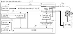
本发明提供的基于幅值可控的多路射频消融系统,包括幅值可控的双路射频电压发生器S1、多路(2至12路可选)射频电压和电流传感器S2、射频电参数检测模块S3、多路(2-12路可选)高速ADC模块S4、主控制器S5、脚踏开关S6、电源系统S7、通信接口S8、人机界面S9、多极导管A2和参考极板A4,参见图2所示。其中:The multi-channel radio frequency ablation system based on the controllable amplitude provided by the present invention includes a dual-channel radio frequency voltage generator S1 with controllable amplitude, multiple (2 to 12 optional) radio frequency voltage and current sensors S2, and radio frequency electrical parameters Detection module S3, multi-channel (2-12 channels optional) high-speed ADC module S4, main controller S5, foot switch S6, power supply system S7, communication interface S8, man-machine interface S9, multi-pole catheter A2 and reference plate A4, see Figure 2. in:
所述幅值可控的双路射频电压发生器S1,由2组独立的DC-DC电源(S10和S11)、2组独立的功率放大电路(S12和S13)、2组独立的主功率变压器(S14和S15)和功率开关阵列S16组成。2组独立的DC-DC电源(S10和S11)提供2路幅值可独立调节的直流电压,这2路直流电压经过2组独立的功率放大电路(S12和S13)的滤波和选频,逆变成2路正弦射频电压;这2路射频电压初始相位和频率相同,具有一定的幅值差,其幅值差由2组独立的DC-DC电源(S10和S11)调节;实际的输出波形见附图4;2组独立的主功率变压器(S14和S15)完成2路正弦射频电压的隔离输出;功率开关阵列S16将此2路具有幅值差的正弦射频电压切换至多路(2至12路可选),并在主控制器S5的控制下以特定的方式释放到组织;The amplitude-controllable dual-channel radio frequency voltage generator S1 consists of 2 sets of independent DC-DC power supplies (S10 and S11), 2 sets of independent power amplifier circuits (S12 and S13), and 2 sets of independent main power transformers (S14 and S15) and a power switch array S16. Two independent DC-DC power supplies (S10 and S11) provide two DC voltages whose amplitudes can be adjusted independently. These two DC voltages are filtered and selected by two independent power amplifier circuits (S12 and S13). It becomes 2 channels of sinusoidal RF voltage; the initial phase and frequency of these 2 channels of RF voltage are the same, with a certain amplitude difference, and the amplitude difference is adjusted by 2 sets of independent DC-DC power supplies (S10 and S11); the actual output waveform See Figure 4; 2 sets of independent main power transformers (S14 and S15) complete the isolated output of the 2-channel sinusoidal RF voltage; the power switch array S16 switches the 2-channel sinusoidal RF voltage with amplitude difference to multiple channels (2 to 12). (Optional), and released to the organization in a specific way under the control of the main controller S5;
所述多路(2至12路可选)射频电压和电流传感器S2,分别隔离衰减双路射频电压发生器S1产生的每一路射频电压和电流信息,得到与输出的射频电压和电流强度成一定比例的信号;The multi-channel (2 to 12 optional) radio frequency voltage and current sensors S2 respectively isolate and attenuate the information of each channel of radio frequency voltage and current generated by the dual-channel radio frequency voltage generator S1, and obtain the output radio frequency voltage and current intensity which is a certain value. proportional signal;
所述射频电参数检测模块S3,分别对每一路正弦射频电压和电流感知信号进行幅值调理和滤波处理;The radio frequency electrical parameter detection module S3 respectively performs amplitude conditioning and filtering processing on each channel of sinusoidal radio frequency voltage and current sensing signals;
所述多路(2至12路可选)高速ADC模块S4,用于对正弦射频电压和电流检测信号进行模数转换;The multi-channel (2 to 12 optional) high-speed ADC modules S4 are used to perform analog-to-digital conversion on the sinusoidal radio frequency voltage and current detection signals;
所述主控制器S5协调整个系统的工作。The main controller S5 coordinates the work of the entire system.
本发明中,幅值可控的多路射频消融系统A1产生多路(2至12路可选)具有幅值差的正弦射频电压,通过多极导管A2释放到心肌病灶部位A3,参考极板A4作为射频电流的回流端连接至幅值可控的双路射频电压发生器S4的负极端。参见图1、图2所示。In the present invention, the amplitude-controllable multi-channel radio frequency ablation system A1 generates multiple (2 to 12 optional) sinusoidal radio frequency voltages with different amplitudes, which are released to the myocardial lesion site A3 through the multi-polar catheter A2, and the reference pole plate A4 is connected to the negative terminal of the amplitude-controllable dual-channel radio frequency voltage generator S4 as the return terminal of the radio frequency current. See Figure 1 and Figure 2.
本发明中,脚踏开关S6通过控制DC-DC模块(S10和S11)的开启或关闭,实现输出射频电压的开启或关闭。电源系统S7将220VAC/50Hz的市电转换成±5V、±12V、±3.3V以及DC-DC模块(S10和S11)所需的直流输入电压。通信接口S8与主控制器S5连接,起到双向传输的作用。通信接口S8将人机界面S9所设置的参数值传输到主控制器S5,以实现系统的控制。通信接口S8将主控制器S5计算出的消融功率、消融阻抗、射频电压、射频电流等检测参数传输到人机界面S9,用以显示实时的消融状态。In the present invention, the foot switch S6 realizes the on or off of the output radio frequency voltage by controlling the on or off of the DC-DC module (S10 and S11). The power system S7 converts the 220VAC/50Hz mains power into ±5V, ±12V, ±3.3V and the DC input voltage required by the DC-DC modules (S10 and S11). The communication interface S8 is connected with the main controller S5, and plays the role of bidirectional transmission. The communication interface S8 transmits the parameter values set by the man-machine interface S9 to the main controller S5 to realize the control of the system. The communication interface S8 transmits detection parameters such as ablation power, ablation impedance, radio frequency voltage, and radio frequency current calculated by the main controller S5 to the man-machine interface S9 to display the real-time ablation state.
本发明中,主控制器S5协调整个系统的工作,其流程见附图3;在系统开始消融前,主控制器S5根据指令设置多路射频电压放电路数、设置多电极放电方式、设置功率开关阵列S16的切换方式和频率、设置多路射频电压幅值及其幅值差、设置射频电压输出功率值、设置放电时间和阻抗限制值;在系统消融时,主控制器S5根据射频电参数检测模块反馈的射频电压和电流信息,计算消融功率、消融阻抗、电压和电流幅值;主控制器将这些数据与设置参数比较,进而调节多路射频电压的输出占空比,从而实现多路射频电压的恒功率控制;当达到所设置的消融时间或阻抗限制值时,主控制器将停止本次消融。In the present invention, the main controller S5 coordinates the work of the entire system, and its process is shown in Figure 3; before the system starts ablation, the main controller S5 sets the number of multi-channel radio frequency voltage discharge circuits, sets the multi-electrode discharge mode, and sets the power according to the instructions. Switching mode and frequency of switch array S16, setting multi-channel RF voltage amplitude and amplitude difference, setting RF voltage output power value, setting discharge time and impedance limit value; during system ablation, main controller S5 according to RF electrical parameters Detect the RF voltage and current information fed back by the module, and calculate the ablation power, ablation impedance, voltage and current amplitude; the main controller compares these data with the setting parameters, and then adjusts the output duty cycle of the multi-channel RF voltage, thereby realizing the multi-channel RF voltage. Constant power control of RF voltage; when the set ablation time or impedance limit value is reached, the main controller will stop the ablation.
本发明提出的幅值可控的多路射频消融方法,在主控制器S5的作用下,进行多种方式放电。通过控制功率开关阵列的切换方式或切换频率,将2路具有幅值差的射频电压切换至多个电极(2至12电极)进行输出;将2路具有幅值差的射频电压以特定的切换方式或切换频率输出到多电极时,可实现多点离散损伤、短连续损伤或长连续损伤。The amplitude-controllable multi-channel radio frequency ablation method proposed by the present invention performs multiple discharges under the action of the main controller S5. By controlling the switching mode or switching frequency of the power switch array, the two RF voltages with amplitude difference are switched to multiple electrodes (2 to 12 electrodes) for output; the two RF voltages with amplitude difference are switched in a specific switching mode Or when switching frequency output to multi-electrode, multi-point discrete damage, short continuous damage or long continuous damage can be realized.
特别地,当具有幅值差的射频电压切换到相邻的消融电极时,由于幅值差的存在,相邻消融电极之间将产生横向流动的消融电流(双极电流);同时消融电极与体表参考极板之间也可产生纵向流动的消融电流(单极电流);双极电流有助于心肌产生线性损伤,而单极电流则有助于增加损伤深度;这种消融方式可提高消融效率,控制消融损伤的形态,特别有利于快速形成具有一定深度的线性损伤或多点离散损伤。In particular, when the radio frequency voltage with the amplitude difference is switched to the adjacent ablation electrodes, due to the existence of the amplitude difference, a lateral flow of ablation current (bipolar current) will be generated between the adjacent ablation electrodes; Longitudinal flow of ablation currents (unipolar currents) can also be generated between the body surface reference plates; bipolar currents contribute to linear damage to the myocardium, while unipolar currents contribute to increased depth of damage; this ablation method can improve Ablation efficiency, controlling the shape of ablation lesions, is particularly beneficial to the rapid formation of linear lesions with a certain depth or multi-point discrete lesions.
附图6-图9列举了系统具有4个消融电极时,功率开关阵列的不同切换方式或切换频率所实现的放电方式:Figures 6 to 9 list the discharge modes realized by different switching modes or switching frequencies of the power switch array when the system has 4 ablation electrodes:
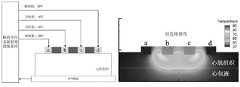
设置功率开关阵列的切换方式1:使高幅值的射频电压切换至外侧2个电极,低幅值的射频电压切换至内侧2个电极时,可产生两点的离散损伤,且离散损伤位于施加的高幅值电极下方;Set the switching mode 1 of the power switch array: when the high-amplitude RF voltage is switched to the outer 2 electrodes, and the low-amplitude RF voltage is switched to the inner 2 electrodes, two discrete damages can be generated, and the discrete damage is located in the applied area. below the high-amplitude electrode;
设置功率开关阵列的切换方式2:使高幅值的射频电压切换至内侧2个电极,低幅值的射频电压切换至外侧2个电极时,可产生短连续损伤;Set the
设置功率开关阵列的切换方式3:将2路具有幅值差的射频电压依次切换到相邻电极时,可产生两点离散损伤,且离散损伤位于施加的高幅值电极下方;Set the
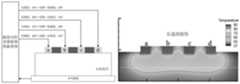
设置功率开关阵列的切换方式4:功率开关阵列以一定的切换频率,将2路具有幅值差的射频电压交替切换至相邻电极,则可产生长连续损伤,且切换频率越快,热损伤越对称和均匀。Set the switching method of the power switch array 4: The power switch array alternately switches the two RF voltages with amplitude difference to adjacent electrodes at a certain switching frequency, which can cause long continuous damage, and the faster the switching frequency, the thermal damage more symmetrical and uniform.
称上述损伤形态为基本损伤形态。The above-mentioned damage pattern is called the basic damage pattern.
本发明包括但不限于输出4路具有幅值差的射频电压,可根据具体要求减少或增加射频电压通道,即增加或减少功率开关阵列个数,可实现2路至12路具有幅值差的射频电压输出。The present invention includes but is not limited to outputting 4 channels of radio frequency voltages with amplitude difference, and can reduce or increase RF voltage channels according to specific requirements, that is, increase or decrease the number of power switch arrays, and can realize 2 channels to 12 channels with amplitude differences. RF voltage output.
在实际临床应用中,可将上述基本损伤形态进行组合得到线性损伤、环形损伤、盒式损伤、十字损伤等;例如,众多单点离散损伤依次叠加可实现线性损伤、长连续损伤的少次叠加也可实现线性损伤、导管90度移动且进行长连续损伤消融,可实现十字损伤;同时通过控制射频电压输出占空比、消融时间、电压幅值及其幅值差、功率开关阵列的切换方式或切换频率可实现对损伤尺寸的控制。本发明提供的消融系统及方法为临床房颤射频消融损伤尺寸和形态的控制提供了新的方案,克服了传统单路心脏射频消融系统较难快速形成连续损伤的缺点。In practical clinical applications, the above basic damage forms can be combined to obtain linear damage, annular damage, box damage, cross damage, etc.; for example, many single-point discrete damages are superimposed in turn to achieve linear damage and long continuous damage. It can also achieve linear injury, 90-degree movement of the catheter and long continuous injury ablation, and cross injury can be achieved; at the same time, by controlling the RF voltage output duty cycle, ablation time, voltage amplitude and its amplitude difference, and the switching method of the power switch array Or switch the frequency to achieve control over the size of the lesions. The ablation system and method provided by the invention provide a new solution for the control of the size and shape of clinical atrial fibrillation radiofrequency ablation lesions, and overcome the disadvantage that the traditional single-channel cardiac radiofrequency ablation system is difficult to rapidly form continuous lesions.
附图说明Description of drawings
图1幅值可控的多路射频消融系统结构示意图。Figure 1 is a schematic structural diagram of a multi-channel radiofrequency ablation system with controllable amplitude.
图2幅值可控的双路射频电压发生器。Figure 2 Amplitude-controllable dual-channel RF voltage generator.
图3多路射频消融系统工作流程图。Fig. 3 Working flow chart of the multi-channel radiofrequency ablation system.
图4两路频率和初始相位相同,幅值分别为62 V和31 V的射频电压波形。Figure 4. The RF voltage waveforms of the two channels with the same frequency and initial phase, and the amplitudes are 62 V and 31 V, respectively.
图5以占空比方式输出的具有幅值差的射频电压。Figure 5. RF voltages with amplitude difference output in duty cycle mode.
图6基于幅值可控的多路射频消融系统实现两点离散损伤的方式。Fig. 6 The way of realizing two-point discrete lesions based on a multi-channel radiofrequency ablation system with controllable amplitude.
图7基于幅值可控的多路射频消融系统实现短连续损伤的方式。Fig. 7 The way to achieve short continuous lesions based on a multi-channel radiofrequency ablation system with controllable amplitude.
图8基于幅值可控的多路射频消融系统实现两点离散损伤的方式。Fig. 8 The way of realizing two-point discrete lesions based on a multi-channel radiofrequency ablation system with controllable amplitude.
图9基于幅值可控的多路射频消融系统实现长连续损伤的方式。Fig. 9 The way of realizing long continuous lesions based on the multi-channel radiofrequency ablation system with controllable amplitude.
具体实施方式Detailed ways
下面结合附图和实施例对本发明提出的幅值可控的多路射频消融系统及方法作进一步说明。本实施例实现了一种4个消融电极时的幅值可控的多路射频消融系统及方法。附图1是幅值可控的多路射频消融系统结构示意。幅值可控的多路射频消融系统A1、多极导管A2、心肌病灶部位A3和参考极板A4共同构成多路射频电流的回路;附图2显示了本发明系统内部的主要功能模块及其连接方式。图2列举了一种2路幅值可控的路射频电压发生器。功率放大器(S12和S13)完成对射频方波小信号(PWM控制器输出)的滤波及功率放大,分别得到2路具有幅值差的射频电压;每路射频电压初始相位和频率相同,幅值可由对应的DC-DC电源(S10和S11)调节;主功率变压器(S14和S15)完成2路射频电压的隔离输出;功率开关阵列S16将此2路射频电压切换至4路输出;本发明包括但不限于输出4路具有幅值差的射频电压,可根据具体要求减少或增加射频电压通道;例如,增加功率开关阵列个数,以实现12路具有幅值差的射频电压输出。The multi-channel radio frequency ablation system and method with controllable amplitude proposed by the present invention will be further described below with reference to the accompanying drawings and embodiments. This embodiment implements a multi-channel radio frequency ablation system and method with controllable amplitude when there are four ablation electrodes. FIG. 1 is a schematic structural diagram of a multi-channel radiofrequency ablation system with controllable amplitude. Amplitude-controllable multi-channel radio frequency ablation system A1, multi-pole catheter A2, myocardial lesion site A3 and reference plate A4 together form a multi-channel radio frequency current circuit; Figure 2 shows the main functional modules inside the system of the present invention and its connection method. Figure 2 lists a 2-channel amplitude-controllable RF voltage generator. The power amplifiers (S12 and S13) complete the filtering and power amplification of the small RF square wave signal (output of the PWM controller), and obtain two RF voltages with different amplitudes respectively; the initial phase and frequency of each RF voltage are the same, and the amplitude It can be adjusted by the corresponding DC-DC power supply (S10 and S11); the main power transformer (S14 and S15) completes the isolation output of 2 channels of radio frequency voltage; the power switch array S16 switches the 2 channels of radio frequency voltage to 4 channels of output; the present invention includes However, it is not limited to outputting 4 channels of RF voltages with different amplitudes. The RF voltage channels can be reduced or increased according to specific requirements; for example, the number of power switch arrays can be increased to achieve 12 channels of RF voltage outputs with different amplitudes.
射频电压和电流传感器S2分别检测各路射频电流和电压信号;射频电参数检测模块S3将对多路(4路)射频电流和电压感知信号进行幅值调节、滤波抗干扰处理、差分信号转单端信号;多路(4路)高速ADC模块S4将对射频电参数检测模块输出的模拟信号进行高速采样和模数转换;主控制器S5将根据反馈的射频电压和电流信息,计算消融功率、消融阻抗、电压和电流幅值;主控制器可实时调节多路(4路)射频电压输出占空比以实现恒功率控制,通过设置射频电压幅值及其幅值差、设置功率开关阵列的切换方式或切换频率、设置多电极放电方式、设置射频电压输出功率值、设置放电时间可实现不同的消融效果。The RF voltage and current sensor S2 respectively detects the RF current and voltage signals of each channel; the RF electrical parameter detection module S3 will perform amplitude adjustment, filtering and anti-interference processing, and differential signal transfer to the multi-channel (4 channels) RF current and voltage sensing signals. The multi-channel (4-channel) high-speed ADC module S4 will perform high-speed sampling and analog-to-digital conversion on the analog signal output by the RF electrical parameter detection module; the main controller S5 will calculate the ablation power, Ablation impedance, voltage and current amplitude; the main controller can adjust the multi-channel (4-channel) RF voltage output duty cycle in real time to achieve constant power control, by setting the RF voltage amplitude and its amplitude difference, setting the power switch array. Switching mode or switching frequency, setting multi-electrode discharge mode, setting RF voltage output power value, and setting discharge time can achieve different ablation effects.
本发明提出的幅值可控的多路射频消融系统及方法,其操作流程如下(见附图3所示);The multi-channel radio frequency ablation system and method with controllable amplitude proposed by the present invention has the following operation process (see FIG. 3 );
(1)开机自检和初始化;(1) POST and initialization;
(2)判断系统状态;(2) Judging the system status;
(3)自检不通过时,系统报警;(3) When the self-test fails, the system alarms;
(4)自检通过时,可进行消融参数设置:包括设置放电路数、多电极放电方式、射频电压幅值差、放电时间、功率开关阵列的切换方式或切换频率、设置阻抗和功率限制值;(4) When the self-test is passed, the ablation parameters can be set: including setting the number of discharge circuits, multi-electrode discharge mode, RF voltage amplitude difference, discharge time, switching mode or switching frequency of the power switch array, setting impedance and power limit value ;
(5)开始消融,此时系统正常工作;(5) Start ablation, and the system works normally at this time;
(6)检测并显示多路消融功率、心肌阻抗值、剩余放电时间;(6) Detect and display multiple ablation power, myocardial impedance value, and residual discharge time;
(7)判断是否达到阻抗和功率限制值;(7) Determine whether the impedance and power limit values are reached;
(8)判断结果为“是”时,暂停消融,同时重新设置消融参数;(8) When the judgment result is "Yes", the ablation is suspended, and the ablation parameters are reset at the same time;
(9)判断结果为“否”时,可继续消融并根据检测值,调节射频电压输出占空比以实现恒功率消融;(9) When the judgment result is "No", the ablation can be continued and the output duty cycle of the radio frequency voltage can be adjusted according to the detected value to achieve constant power ablation;
(10)放电时间结束停止消融。(10) Stop ablation at the end of the discharge time.
附图4列举了具有幅值差的射频电压的实际波形,2路射频电压幅值分别为62V和31V,具有相同的初始相位和频率值。附图5列举了以占空比方式输出的2路射频电压,主控制器通过控制功率开关阵列的通断,实现对每路输出射频电压占空比的调节,进而实现对每路射频输出功率的控制。FIG. 4 lists the actual waveforms of radio frequency voltages with different amplitudes. The amplitudes of the two radio frequency voltages are 62V and 31V, respectively, and have the same initial phase and frequency values. Accompanying drawing 5 enumerates the 2-way radio frequency voltage output in duty cycle mode, the main controller realizes the regulation of the duty ratio of each output radio frequency voltage by controlling the on-off of the power switch array, and then realizes the adjustment of the output power of each channel of radio frequency. control.
附图6-图9列举了幅值可控的多路射频消融系统的放电方式及其在心肌中产生的热损伤特征;本发明通过对特定电极施加具有幅值差的射频电压,可在生物组织上实现多种损伤形态,如离散损伤、短连续损伤和长连续损伤;在实际临床应用中,将上述基本损伤形态进行叠加和组合可得到线性损伤、环形损伤、盒式损伤、十字损伤等;同时通过控制射频电压输出占空比、消融时间、射频电压幅值及其幅值差等可实现对损伤尺寸的控制。Figures 6 to 9 enumerate the discharge mode of the amplitude-controllable multi-channel radiofrequency ablation system and the thermal damage characteristics generated in the myocardium; Various damage forms are realized on the tissue, such as discrete damage, short continuous damage and long continuous damage; in practical clinical applications, the above basic damage forms can be superimposed and combined to obtain linear damage, annular damage, box damage, cross damage, etc. At the same time, the damage size can be controlled by controlling the RF voltage output duty cycle, ablation time, RF voltage amplitude and its amplitude difference.
附图6是实现2点离散损伤的方式;在该放电方式下,主控制器通过使能信号控制功率开关阵列的切换。以2路射频电压分别为40V和20V为例,在主控制器的控制下,功率开关阵列将40V的射频电压释放到外侧电极a和d、将20V的射频电压释放到内侧电极b和c;参考极板连接至参考零电位;在该模式下,可实现2点的离散损伤,热损伤位于a&d电极下方。FIG. 6 is a way to realize 2-point discrete damage; in this discharge mode, the main controller controls the switching of the power switch array through an enable signal. Taking the two RF voltages as 40V and 20V as an example, under the control of the main controller, the power switch array releases the 40V RF voltage to the outer electrodes a and d, and the 20V RF voltage to the inner electrodes b and c; The reference plate is connected to the reference zero potential; in this mode, a 2-point discrete damage is achieved, with thermal damage below the a&d electrodes.
附图7是实现短连续损伤的方式;在该放电方式下,主控制器通过使能信号控制功率开关阵列的切换。以2路射频电压分别为40V和20V为例,在主控制器的控制下,功率开关阵列将40V的射频电压释放到内侧电极b和c、将20V的射频电压释放到外侧电极a和d;参考极板连接至参考零电位;在该模式下,可实现短连续损伤。FIG. 7 shows a method for realizing short continuous damage; in this discharge mode, the main controller controls the switching of the power switch array through an enable signal. Taking the two RF voltages as 40V and 20V as an example, under the control of the main controller, the power switch array releases the 40V RF voltage to the inner electrodes b and c, and the 20V RF voltage to the outer electrodes a and d; The reference plate is connected to the reference zero potential; in this mode, short continuous damage can be achieved.
附图8是另一种实现2点离散损伤的方式;在该放电方式下,主控制器通过使能信号控制功率开关阵列的切换。以2路射频电压分别为40V和20V为例,在主控制器的控制下,功率开关阵列将40V和20V的射频电压分别释放到a&c电极和b&d电极;参考极板连接至参考零电位;在该模式下,可实现2点的离散损伤,热损伤位于a&c电极下方。FIG. 8 is another way to realize 2-point discrete damage; in this discharge mode, the main controller controls the switching of the power switch array through the enable signal. Taking the two RF voltages as 40V and 20V as an example, under the control of the main controller, the power switch array releases the 40V and 20V RF voltages to the a&c electrodes and the b&d electrodes respectively; the reference plate is connected to the reference zero potential; In this mode, 2 points of discrete damage can be achieved, and the thermal damage is located below the a&c electrodes.
附图9是实现长连续损伤的方式;在该放电方式下,主控制器通过使能信号控制功率开关阵列的切换。以2路射频电压分别为40V和20V为例,在主控制器的控制下,功率开关阵列将40V和20V的射频电压以交替施加的方式分别释放到a&c电极和b&d电极;参考极板连接至参考零电位;在该模式下,可实现长连续损伤,且交替周期越小(功率开关阵列的切换频率越高),热损伤越均匀和对称。FIG. 9 shows the way of realizing long continuous damage; in this discharge way, the main controller controls the switching of the power switch array through the enable signal. Taking the two RF voltages as 40V and 20V as an example, under the control of the main controller, the power switch array releases the RF voltages of 40V and 20V to the a&c electrodes and the b&d electrodes in an alternate manner; the reference plate is connected to the Reference zero potential; in this mode, long continuous damage can be achieved, and the smaller the alternating period (the higher the switching frequency of the power switch array), the more uniform and symmetrical the thermal damage is.
Claims (1)
Translated fromChinesePriority Applications (1)
| Application Number | Priority Date | Filing Date | Title |
|---|---|---|---|
| CN201910338467.XACN110063786B (en) | 2019-04-25 | 2019-04-25 | Amplitude-controllable multi-channel radiofrequency ablation system |
Applications Claiming Priority (1)
| Application Number | Priority Date | Filing Date | Title |
|---|---|---|---|
| CN201910338467.XACN110063786B (en) | 2019-04-25 | 2019-04-25 | Amplitude-controllable multi-channel radiofrequency ablation system |
Publications (2)
| Publication Number | Publication Date |
|---|---|
| CN110063786A CN110063786A (en) | 2019-07-30 |
| CN110063786Btrue CN110063786B (en) | 2022-05-20 |
Family
ID=67368904
Family Applications (1)
| Application Number | Title | Priority Date | Filing Date |
|---|---|---|---|
| CN201910338467.XAActiveCN110063786B (en) | 2019-04-25 | 2019-04-25 | Amplitude-controllable multi-channel radiofrequency ablation system |
Country Status (1)
| Country | Link |
|---|---|
| CN (1) | CN110063786B (en) |
Families Citing this family (4)
| Publication number | Priority date | Publication date | Assignee | Title |
|---|---|---|---|---|
| CN211633554U (en)* | 2020-01-10 | 2020-10-09 | 上海魅丽纬叶医疗科技有限公司 | Radio frequency ablation control system |
| CN112244993B (en)* | 2020-10-31 | 2022-03-15 | 杭州诺生医疗科技有限公司 | radiofrequency ablation device |
| CN114271927B (en)* | 2021-12-19 | 2023-10-17 | 复旦大学 | A method and radiofrequency ablation device that can predict the depth of radiofrequency ablation damage in arrhythmias in real time |
| CN117717409A (en)* | 2023-12-19 | 2024-03-19 | 上海睿速创生医疗科技有限公司 | Safe intelligent high-frequency electrotome host computer combined with nerve monitoring |
Citations (1)
| Publication number | Priority date | Publication date | Assignee | Title |
|---|---|---|---|---|
| CN208481456U (en)* | 2017-09-28 | 2019-02-12 | 四川锦江电子科技有限公司 | A kind of radio frequency ablation device with interpolar discharge function |
Family Cites Families (7)
| Publication number | Priority date | Publication date | Assignee | Title |
|---|---|---|---|---|
| US5383917A (en)* | 1991-07-05 | 1995-01-24 | Jawahar M. Desai | Device and method for multi-phase radio-frequency ablation |
| US6635056B2 (en)* | 2001-10-09 | 2003-10-21 | Cardiac Pacemakers, Inc. | RF ablation apparatus and method using amplitude control |
| US8556891B2 (en)* | 2010-03-03 | 2013-10-15 | Medtronic Ablation Frontiers Llc | Variable-output radiofrequency ablation power supply |
| US8747399B2 (en)* | 2010-04-06 | 2014-06-10 | Arthrocare Corporation | Method and system of reduction of low frequency muscle stimulation during electrosurgical procedures |
| CN202305653U (en)* | 2010-06-01 | 2012-07-04 | 谭伟 | Radio frequency ablation signal feedback circuit |
| US9005193B2 (en)* | 2010-11-08 | 2015-04-14 | Biosense Webster (Israel) Ltd. | Multichannel ablation with frequency differentiation |
| CN109157280A (en)* | 2018-08-10 | 2019-01-08 | 重庆大学 | Irreversible electroporated tissue ablation effect dynamic realtime assessment equipment |
- 2019
- 2019-04-25CNCN201910338467.XApatent/CN110063786B/enactiveActive
Patent Citations (1)
| Publication number | Priority date | Publication date | Assignee | Title |
|---|---|---|---|---|
| CN208481456U (en)* | 2017-09-28 | 2019-02-12 | 四川锦江电子科技有限公司 | A kind of radio frequency ablation device with interpolar discharge function |
Non-Patent Citations (1)
| Title |
|---|
| Theoretical and experimental analysis of amplitude control ablation and bipolar ablation in creating linear lesion and discrete lesions for treating atrial fibrillation;Shengjie Yan etal;《International Journal of Hyperthermia》;20170215;第33卷(第6期);第608-616页* |
Also Published As
| Publication number | Publication date |
|---|---|
| CN110063786A (en) | 2019-07-30 |
Similar Documents
| Publication | Publication Date | Title |
|---|---|---|
| CN110063786B (en) | Amplitude-controllable multi-channel radiofrequency ablation system | |
| CN110693605B (en) | High-voltage pulse system for cardiac ablation | |
| CN111227926B (en) | Pulser for irreversible electroporation | |
| JP7430794B2 (en) | Adjust the delivery of irreversible electroporation pulses depending on the transferred energy | |
| WO2020140440A1 (en) | Electrocardiogram waveform-based adaptive pulse ablation instrument | |
| US8298225B2 (en) | System and method for return electrode monitoring | |
| JP7719227B2 (en) | System for localized ablation | |
| JP2002513617A (en) | RF ablation device and method using monopolar and bipolar technology | |
| EP3831324B1 (en) | Medical apparatus for irreversible electroporation | |
| WO2023098896A1 (en) | Closed-loop control system for pulse ablation | |
| WO2022233245A1 (en) | Device for implementing cooperation between high-voltage electrical pulse ablation and electrophysiological recorder | |
| US20230009191A1 (en) | Irreversible electroporation and thermal ablation by focal catheter | |
| CN103893914A (en) | Program control multichannel electrophysiological stimulator | |
| CN112914717A (en) | High-voltage high-frequency pulse electric field ablation instrument based on double-gate control technology | |
| JP2022162997A (en) | Pulse generator for irreversible electroporation with switchable pulse application | |
| CN116269731A (en) | Pulsed electric field ablation system | |
| WO2023006111A1 (en) | High-voltage transmitting circuit for catheter, and ablation tool | |
| CN113576652B (en) | Composite steep pulse treatment equipment for automatically monitoring and adjusting ablation parameters | |
| CN114869453A (en) | A Steep Pulse Electric Field Ablation Control System | |
| US20210228261A1 (en) | Pulse generator for irreversible electroporation with switchable pulse application | |
| CN108852503B (en) | Frequency-controllable multi-source radiofrequency ablation system | |
| JP2025146904A (en) | System for localized ablation | |
| CN117838283A (en) | Nanosecond pulse ablation system |
Legal Events
| Date | Code | Title | Description |
|---|---|---|---|
| PB01 | Publication | ||
| PB01 | Publication | ||
| SE01 | Entry into force of request for substantive examination | ||
| SE01 | Entry into force of request for substantive examination | ||
| GR01 | Patent grant | ||
| GR01 | Patent grant |