CN110062603B - Multiphoton endoscopic microscope for vertical cross-section imaging - Google Patents
Multiphoton endoscopic microscope for vertical cross-section imagingDownload PDFInfo
- Publication number
- CN110062603B CN110062603BCN201780074828.3ACN201780074828ACN110062603BCN 110062603 BCN110062603 BCN 110062603BCN 201780074828 ACN201780074828 ACN 201780074828ACN 110062603 BCN110062603 BCN 110062603B
- Authority
- CN
- China
- Prior art keywords
- axial
- mirror
- scanning
- scan
- multiphoton
- Prior art date
- Legal status (The legal status is an assumption and is not a legal conclusion. Google has not performed a legal analysis and makes no representation as to the accuracy of the status listed.)
- Active
Links
Images


Classifications
- G—PHYSICS
- G02—OPTICS
- G02B—OPTICAL ELEMENTS, SYSTEMS OR APPARATUS
- G02B21/00—Microscopes
- G02B21/0004—Microscopes specially adapted for specific applications
- G02B21/002—Scanning microscopes
- G02B21/0024—Confocal scanning microscopes (CSOMs) or confocal "macroscopes"; Accessories which are not restricted to use with CSOMs, e.g. sample holders
- G02B21/0036—Scanning details, e.g. scanning stages
- G02B21/0048—Scanning details, e.g. scanning stages scanning mirrors, e.g. rotating or galvanomirrors, MEMS mirrors
- G—PHYSICS
- G02—OPTICS
- G02B—OPTICAL ELEMENTS, SYSTEMS OR APPARATUS
- G02B21/00—Microscopes
- G02B21/0004—Microscopes specially adapted for specific applications
- G02B21/002—Scanning microscopes
- G02B21/0024—Confocal scanning microscopes (CSOMs) or confocal "macroscopes"; Accessories which are not restricted to use with CSOMs, e.g. sample holders
- G02B21/0052—Optical details of the image generation
- G02B21/0076—Optical details of the image generation arrangements using fluorescence or luminescence
- A—HUMAN NECESSITIES
- A61—MEDICAL OR VETERINARY SCIENCE; HYGIENE
- A61B—DIAGNOSIS; SURGERY; IDENTIFICATION
- A61B1/00—Instruments for performing medical examinations of the interior of cavities or tubes of the body by visual or photographical inspection, e.g. endoscopes; Illuminating arrangements therefor
- A61B1/00163—Optical arrangements
- A61B1/00172—Optical arrangements with means for scanning
- A—HUMAN NECESSITIES
- A61—MEDICAL OR VETERINARY SCIENCE; HYGIENE
- A61B—DIAGNOSIS; SURGERY; IDENTIFICATION
- A61B1/00—Instruments for performing medical examinations of the interior of cavities or tubes of the body by visual or photographical inspection, e.g. endoscopes; Illuminating arrangements therefor
- A61B1/06—Instruments for performing medical examinations of the interior of cavities or tubes of the body by visual or photographical inspection, e.g. endoscopes; Illuminating arrangements therefor with illuminating arrangements
- A61B1/063—Instruments for performing medical examinations of the interior of cavities or tubes of the body by visual or photographical inspection, e.g. endoscopes; Illuminating arrangements therefor with illuminating arrangements for monochromatic or narrow-band illumination
- G—PHYSICS
- G02—OPTICS
- G02B—OPTICAL ELEMENTS, SYSTEMS OR APPARATUS
- G02B21/00—Microscopes
- G02B21/0004—Microscopes specially adapted for specific applications
- G02B21/002—Scanning microscopes
- G—PHYSICS
- G02—OPTICS
- G02B—OPTICAL ELEMENTS, SYSTEMS OR APPARATUS
- G02B23/00—Telescopes, e.g. binoculars; Periscopes; Instruments for viewing the inside of hollow bodies; Viewfinders; Optical aiming or sighting devices
- G02B23/24—Instruments or systems for viewing the inside of hollow bodies, e.g. fibrescopes
- G02B23/2407—Optical details
- G02B23/2461—Illumination
- G02B23/2469—Illumination using optical fibres
- G—PHYSICS
- G02—OPTICS
- G02B—OPTICAL ELEMENTS, SYSTEMS OR APPARATUS
- G02B23/00—Telescopes, e.g. binoculars; Periscopes; Instruments for viewing the inside of hollow bodies; Viewfinders; Optical aiming or sighting devices
- G02B23/24—Instruments or systems for viewing the inside of hollow bodies, e.g. fibrescopes
- G02B23/2476—Non-optical details, e.g. housings, mountings, supports
- G—PHYSICS
- G02—OPTICS
- G02B—OPTICAL ELEMENTS, SYSTEMS OR APPARATUS
- G02B26/00—Optical devices or arrangements for the control of light using movable or deformable optical elements
- G02B26/08—Optical devices or arrangements for the control of light using movable or deformable optical elements for controlling the direction of light
- G02B26/10—Scanning systems
- G02B26/101—Scanning systems with both horizontal and vertical deflecting means, e.g. raster or XY scanners
- G—PHYSICS
- G01—MEASURING; TESTING
- G01N—INVESTIGATING OR ANALYSING MATERIALS BY DETERMINING THEIR CHEMICAL OR PHYSICAL PROPERTIES
- G01N21/00—Investigating or analysing materials by the use of optical means, i.e. using sub-millimetre waves, infrared, visible or ultraviolet light
- G01N21/62—Systems in which the material investigated is excited whereby it emits light or causes a change in wavelength of the incident light
- G01N21/63—Systems in which the material investigated is excited whereby it emits light or causes a change in wavelength of the incident light optically excited
- G01N21/64—Fluorescence; Phosphorescence
- G01N21/645—Specially adapted constructive features of fluorimeters
- G01N21/6456—Spatial resolved fluorescence measurements; Imaging
- G01N21/6458—Fluorescence microscopy
Landscapes
- Physics & Mathematics (AREA)
- Optics & Photonics (AREA)
- Health & Medical Sciences (AREA)
- Life Sciences & Earth Sciences (AREA)
- General Physics & Mathematics (AREA)
- Surgery (AREA)
- Analytical Chemistry (AREA)
- Chemical & Material Sciences (AREA)
- Biomedical Technology (AREA)
- Animal Behavior & Ethology (AREA)
- Pathology (AREA)
- Radiology & Medical Imaging (AREA)
- Veterinary Medicine (AREA)
- Engineering & Computer Science (AREA)
- Biophysics (AREA)
- Heart & Thoracic Surgery (AREA)
- Medical Informatics (AREA)
- Molecular Biology (AREA)
- Nuclear Medicine, Radiotherapy & Molecular Imaging (AREA)
- General Health & Medical Sciences (AREA)
- Public Health (AREA)
- Astronomy & Astrophysics (AREA)
- Microscoopes, Condenser (AREA)
- Mechanical Optical Scanning Systems (AREA)
Abstract
Description
Translated fromChinese政府支持声明Statement of Government Support
本发明是以国立卫生研究院授予的EB020644和CA142750拨款在政府支持下完成的。政府对本发明享有一定权利。This invention was made with government support under grants EB020644 and CA142750 awarded by the National Institutes of Health. The government has certain rights in this invention.
相关申请的交叉引用Cross References to Related Applications
本申请要求名称为“具有远程MEMS扫描机构的多光子内窥显微镜中的垂直光束扫描(Vertical Beam Scanning In Multi-Photon Endomicroscopy with Remote MEMSScanning Mechanisms)”并于2016年12月2日提交的美国临时申请第62/429,438号的优先权,所述临时申请全文以引用的方式并入本文。This application claims a U.S. Provisional Application entitled "Vertical Beam Scanning In Multi-Photon Endomicroscopy with Remote MEMSScanning Mechanisms" and filed on December 2, 2016 Priority No. 62/429,438, said provisional application is hereby incorporated by reference in its entirety.
技术领域technical field
本公开总体涉及用于使用光学仪器对组织成像的技术,并且更具体地涉及用于使用光学仪器使得可进行二维(2D)和三维(3D)扫描的技术。The present disclosure relates generally to techniques for imaging tissue using optical instruments, and more particularly to techniques for using optical instruments to enable two-dimensional (2D) and three-dimensional (3D) scanning.
背景技术Background technique
本文提供的背景描述是为了总体上呈现本公开的背景。就本背景技术部分中所描述的程度而言,当前署名的发明人的工作,以及在提交时可不以其它方式具有资格作为现有技术的描述的方面,既不明确地也不隐含地被承认为本公开的现有技术。The background description provided herein is for the purpose of generally presenting the context of the disclosure. To the extent described in this Background section, the work of the presently named inventors, and aspects that would not otherwise qualify as descriptions of prior art at the time of filing, are neither expressly nor implicitly admitted to be prior art to the present disclosure.
内窥显微镜通常用于以平行于组织的表面的水平平面扫描对象。然而,垂直平面(在本文中也称为轴向平面或组织内平面)可对于对垂直于组织表面发育的生物过程、如正常上皮发育、干细胞迁移和肿瘤侵袭的过程进行成像更有用。对体内生物过程的垂直平面进行成像的需求推动了许多微型仪器(包括多光子显微镜装置)设计的开发。然而,先前的设计都不提供生成实时横截面图像所需的轴向位移和扫描速度,并且先前的设计都不以不严重损害样本的可用的形状因子这样做。举例来说,常规的内窥显微镜体积庞大并且不可重复进入待成像的区域,如结肠。Endoscopic microscopes are typically used to scan objects in a horizontal plane parallel to the surface of the tissue. However, a vertical plane (also referred to herein as an axial plane or an intra-tissue plane) may be more useful for imaging biological processes that develop perpendicular to the tissue surface, such as processes of normal epithelial development, stem cell migration, and tumor invasion. The need to image the vertical plane of biological processes in vivo has driven the development of many designs of miniaturized instruments, including multiphoton microscopy setups. However, none of the previous designs provided the axial displacement and scanning speed required to generate real-time cross-sectional images, and none of the previous designs did so in a usable form factor that did not seriously compromise the sample. For example, conventional endoscopic microscopes are bulky and do not have reproducible access to areas to be imaged, such as the colon.
多光子显微镜使用长波长光的强脉冲提供高分辨率和显著的成像深度,所述长波长光的强脉冲能够穿透图像表面以通过非线性效应激发更短波长的光子。相对于其它深组织光学成像模态,多光子显微镜除了与各种靶向荧光生物标记物的相容性之外,还具有减少光漂白和激发内源荧光的能力的益处。Multiphoton microscopy provides high resolution and remarkable imaging depth using intense pulses of long-wavelength light that can penetrate the image surface to excite shorter-wavelength photons through nonlinear effects. Compared to other deep-tissue optical imaging modalities, multiphoton microscopy has the benefit of reduced photobleaching and the ability to excite endogenous fluorescence, in addition to its compatibility with a variety of targeted fluorescent biomarkers.
尽管有许多微型多光子仪器,但仍需要可通过轴向光束扫描对组织进行深度成像的内窥显微镜。能够进行深度成像的现有系统利用传统的台式显微镜,因此增加了实验复杂性、研究侵袭性和生物学行为。Despite the availability of many miniature multiphoton instruments, there is still a need for endoscopic microscopes that can image tissue in depth through axial beam scanning. Existing systems capable of depth imaging utilize conventional benchtop microscopes, thus increasing experimental complexity and studying invasiveness and biological behavior.
为了在小型仪器中最好地利用多光子成像能力,期望支持超快激光的快速轴向(即,垂直或组织内)扫描。足够快速的轴向扫描可支持体内垂直光学切片,从而提供组织学家用于诊断和监测如结肠癌或食道癌的疾病的同一平面中的组织的实时横截面图像。然而,先前的内窥镜仪器为在多光子成像期间改变焦深提供了有限的支持。几个面对多光子内窥镜已经表征了平面外或z轴的分辨率,但仅通过物理移动被成像的样本。当在z轴上移动时,保持水平成像平面以提供清晰图像是特别重要的。To best exploit multiphoton imaging capabilities in small instruments, it is desirable to support fast axial (ie, vertical or intratissue) scanning of ultrafast lasers. Sufficiently fast axial scanning can support vertical optical sectioning in vivo, providing real-time cross-sectional images of tissue in the same plane that histologists use to diagnose and monitor diseases such as colon or esophageal cancer. However, previous endoscopic instruments provided limited support for changing the depth of focus during multiphoton imaging. Several face-to-face multiphoton endoscopes have characterized out-of-plane or z-axis resolution, but only by physically moving the sample being imaged. It is especially important to maintain a horizontal imaging plane to provide sharp images when moving in the z-axis.
为了在垂直平面中创建图像,获取并且然后重建一系列水平平面图像。这种方法通常很慢并且难以实现,因为样品中的振动可导致运动伪影。To create an image in the vertical plane, a series of horizontal plane images are acquired and then reconstructed. This method is often slow and difficult to implement because vibrations in the sample can cause motion artifacts.
现有的扫描系统经常使用许多需要大的远端光学器件(例如,5-10mm)的大致动器生成光学透镜组件的轴向移动。这些系统可在轴向方向上采用Lissajous扫描或“平面内”扫描,其中成像装置必须移动到期望的深度、停止、扫描组织,然后行进到下一个期望的深度并重复此过程。在双轴共聚焦显微镜中,可采用压电致动,并且还可在X-Y和X-Z平面之间使用可选择的Lissajous扫描。在具有光栅或“平面外”扫描能力的系统中,只可在X-Z平面中进行成像。这些系统还需要大的远端光学器件。Existing scanning systems often generate axial movement of the optical lens assembly using many large actuators requiring large distal optics (eg, 5-10 mm). These systems may employ Lissajous scanning or "in-plane" scanning in the axial direction, where the imaging device must move to a desired depth, stop, scan tissue, then proceed to the next desired depth and repeat the process. In dual-axis confocal microscopy, piezo actuation is available and optional Lissajous scanning between the X-Y and X-Z planes is also available. In systems with raster or "out-of-plane" scanning capability, imaging is only possible in the X-Z plane. These systems also require large distal optics.
发明内容Contents of the invention
本申请描述了一种手持式光学装置,所述手持式光学装置可用作用于实时3D光学成像的显微镜系统。用于多光子内窥显微镜的系统利用微型垂直致动器,以除了使用微型化设备的大轴向(即垂直)位移之外,还提供快速轴向扫描。使用静电和薄膜压电致动器结合多光子成像模态获得垂直致动。轴向扫描基于可实现高速度和大位移扫描的静电驱动和参数共振实现。此外,此轴向扫描(即,沿Z轴)可与横向扫描结合,也可基于静电致动和参数共振,所述静电致动和参数共振能够扫描不同平面轴(即,X轴和Y轴)上方的光束。此外,此横向扫描可在不同的轴向扫描深度处实现,而不会改变扫描性能。轴向扫描器的不同共振模式与横向扫描器的共振模式的使用进一步允许在不同方向上更好地隔离扫描控制。The present application describes a handheld optical device that can be used as a microscope system for real-time 3D optical imaging. Systems for multiphoton endoscopy utilize miniature vertical actuators to provide fast axial scanning in addition to large axial (ie, vertical) displacements using miniaturized devices. Vertical actuation was obtained using electrostatic and thin-film piezoelectric actuators combined with multiphoton imaging modalities. Axial scanning is based on electrostatic actuation and parametric resonance enabling high-speed and large-displacement scanning. Furthermore, this axial scanning (i.e., along the Z axis) can be combined with transverse scanning, and can also be based on electrostatic actuation and parametric resonance capable of scanning different planar axes (i.e., X and Y axes). ) above the beam. Furthermore, this lateral scanning can be achieved at different axial scanning depths without changing the scanning performance. The use of different resonance modes of the axial scanner from that of the transverse scanner further allows for better isolation of scan control in different directions.
与共聚焦成像相比,多光子成像为上皮和其它区域的实时体内成像提供了许多益处。举例来说,多光子成像可提供更大的图像深度、更少的光漂白用于长期成像研究,并且还可提供增加的图像分辨率或减少的散射。虽然双轴共聚焦显微镜已经显示出具有可比较的成像深度和垂直切片分辨率的潜力,但由于需要在离轴角度提供光路径,因此需要更大的仪器直径以获得相等的深度。因为单个激发波长可激发多个荧光团,所以多光子成像比其它成像模态(如磁共振成像(MRI)和正电子发射断层扫描(PET))显著容易复用。进一步地,与其它技术相比,多光子激发产生减少的光损伤和平面外光漂白。多光子系统对入射光和返回光使用单个光路径(尽管路径可被分离以用于收集目的),因此,与双轴成像系统相比,使用圆镜几何形状(与双轴使用的一般狗骨几何体相反)。进一步地,双轴系统中的透镜布置需要使用如抛物面固定镜的机构精确对准两个准直透镜,以确保分离的光束路径在同一点对准。多光子布置不具有这种对准问题,尽管这些系统需要适当的中继透镜配置来将扫描镜的轴向位移的改变映射到组织中的焦点的位移。本技术的一个优点是可在不需要使用组织和/或细胞的内源荧光的荧光标记的情况下进行成像。Multiphoton imaging offers many benefits for real-time in vivo imaging of epithelium and other regions compared to confocal imaging. For example, multiphoton imaging may provide greater image depth, less photobleaching for long-term imaging studies, and may also provide increased image resolution or reduced scatter. While dual-axis confocal microscopy has shown the potential for comparable imaging depth and vertical section resolution, larger instrument diameters are required to achieve equivalent depth due to the need to provide light paths at off-axis angles. Because a single excitation wavelength can excite multiple fluorophores, multiphoton imaging is significantly easier to multiplex than other imaging modalities such as magnetic resonance imaging (MRI) and positron emission tomography (PET). Further, multiphoton excitation produces reduced photodamage and out-of-plane photobleaching compared to other techniques. Multiphoton systems use a single optical path for the incoming and returning light (although the paths can be split for collection purposes) and therefore use circular mirror geometries (compared to the general dog-bone used by dual-axis) compared to dual-axis imaging systems. geometry instead). Further, the lens arrangement in a dual-axis system requires precise alignment of the two collimating lenses using mechanisms such as parabolic fixed mirrors to ensure that the split beam paths are aligned at the same point. Multiphoton arrangements do not have this alignment problem, although these systems require an appropriate relay lens configuration to map changes in the axial displacement of the scan mirror to a displacement of the focal point in the tissue. An advantage of this technique is that imaging can be performed without the need for fluorescent labeling using the endogenous fluorescence of the tissue and/or cells.
本申请的系统使用镜扫描方法提供对组织的实时、轴向或垂直扫描。镜的这种轴向移动可使用薄膜压电和/或静电致动器来执行,所述薄膜压电和/或静电致动器可提供相当大的位移(例如,大约500微米),同时仍然具有小直径(例如,大约3mm)。薄膜压电致动器可在较低的操作电压下产生较大的轴向平移,并且能够单独寻址致动腿以补偿不均匀的运动。静电致动器制作起来相对简单并且在较高的操作速度下起作用。另外,如果镜表面是单片构建的(即,作为单个部件),则装置将具有更好的初始均匀性。The system of the present application provides real-time, axial or vertical scanning of tissue using a mirror scanning method. Such axial movement of the mirror can be performed using thin film piezoelectric and/or electrostatic actuators that can provide considerable displacement (e.g., about 500 microns) while still Has a small diameter (eg, about 3 mm). Thin-film piezoelectric actuators can generate large axial translations at lower operating voltages and enable individually addressable actuation legs to compensate for uneven motion. Electrostatic actuators are relatively simple to make and function at high operating speeds. Additionally, if the mirror surface is built monolithically (ie, as a single part), the device will have better initial uniformity.
本多光子成像系统使用双光子效应,当两个较低能量(即较长波长)的光子同时到达生物分子以激发荧光时,会发生所述双光子效应。吸收两个光子的概率随着强度的平方而增加;因此,单轴配置中的高数值孔径物镜用于最大化焦点处的强度。由于这种物理原理,与单光子荧光相比,对组织散射的敏感性较低,并且光漂白减少。另外,使用的较长激发波长提供较深的组织穿透。The present multiphoton imaging system uses the two-photon effect, which occurs when two photons of lower energy (ie, longer wavelength) reach a biomolecule simultaneously to excite fluorescence. The probability of absorbing two photons increases with the square of the intensity; therefore, high numerical aperture objectives in a single-axis configuration are used to maximize the intensity at the focal point. Due to this physical principle, sensitivity to tissue scattering is lower and photobleaching is reduced compared to single-photon fluorescence. In addition, the longer excitation wavelength used provides deeper tissue penetration.
根据实例,多光子光学探针包括探针壳体、联接到横向镜组件并且至少部分地设置在探针壳体中的横向扫描台,以及联接到轴向镜组件并且至少部分地设置在探针壳体中的轴向扫描台。探针壳体具有近端和定位在样品处的远端,并且适于产生输出激光能量。横向扫描台适于通过移动横向镜组件在样品的平面扫描区域上扫描输出激光能量。轴向扫描台适于在样品的深度范围内扫描输出激光能量。深度范围和平面扫描区域形成三维体积。轴向扫描台包括围绕轴向镜组件轴向地定位的多个致动腿。According to an example, a multiphoton optical probe includes a probe housing, a transverse scanning stage coupled to a transverse mirror assembly and disposed at least partially in the probe housing, and a transverse scanning stage coupled to an axial mirror assembly and disposed at least partially in the probe housing. Axial scanning stage in housing. The probe housing has a proximal end and a distal end positioned at the sample and is adapted to generate output laser energy. The transverse scanning stage is adapted to scan and output laser energy on the planar scanning area of the sample by moving the transverse mirror assembly. The axial scanning stage is adapted to scan output laser energy through the depth of the sample. The depth range and planar scan area form a three-dimensional volume. The axial scanning stage includes a plurality of actuation legs positioned axially about the axial mirror assembly.
在一些实例中,用于多光子光学探针的轴向扫描台包括框架、联接到框架的镜平台、联接到框架和镜平台的多个致动器腿,以及围绕镜平台定位的多个电连接器。镜平台适于支撑镜元件。致动器腿适于沿垂直轴升高镜平台。致动器腿和电连接器围绕镜平台轴向地定位。In some examples, an axial scanning stage for a multiphoton optical probe includes a frame, a mirror platform coupled to the frame, a plurality of actuator legs coupled to the frame and the mirror platform, and a plurality of electric motors positioned around the mirror platform. Connector. The mirror platform is adapted to support a mirror element. The actuator legs are adapted to raise the mirror platform along a vertical axis. The actuator legs and electrical connectors are positioned axially about the mirror platform.
附图说明Description of drawings
为了更完整地理解本公开,应该参考以下详细描述和附图,其中相似的附图标号表示附图中的相似元件,并且其中:For a more complete understanding of the present disclosure, reference should be made to the following detailed description and drawings, wherein like reference numerals indicate like elements in the drawings, and in which:
图1A是具有轴向扫描单元、横向扫描单元和远端光学器件的光学探针的示意图,并且图1B是根据各种实施例的具有轴向和横向扫描单元和远端光学器件的实例多光子光学探针的图示;1A is a schematic diagram of an optical probe with an axial scanning unit, a lateral scanning unit, and distal optics, and FIG. 1B is an example multiphoton probe with axial and lateral scanning units and distal optics, according to various embodiments. Illustration of the optical probe;
图2是根据各种实施例的图1的光学探针的示意图;Figure 2 is a schematic illustration of the optical probe of Figure 1, according to various embodiments;
图3A至图3C示出了根据各种实施例的实例横向扫描单元的俯视平面图(图3A)和分别描绘了内轴和外轴的机械扫描角大于5.5度的频率响应图(图3B和图3C);3A-3C illustrate a top plan view ( FIG. 3A ) and frequency response graphs depicting mechanical scan angles of greater than 5.5 degrees on the inner and outer axes, respectively, according to various embodiments ( FIGS. 3B and 3B ). 3C);
图4A至图4K是根据各种实施例的实例轴向扫描单元的俯视平面图(图4A)、示出垂直位移的频率响应图(图4B),以及在示出在静止状态和在440Hz处共振的激光束斑点的激光位移传感器下表征的单元(图4C和图4D)、在移动轴向致动器时波前的变化的图示(图4E至图4G)、在平移轴向致动器时X轴的倾斜角(图4H)和Y轴的倾斜角(图4I)、描绘轴向扫描镜的位置与焦平面的深度之间的线性关系的图示(图J),以及描绘在变化的成像深度上的横向放大率范围的图示(其中轴向扫描单元使用共振静电致动器来提供轴向移动);4A-4K are top plan views ( FIG. 4A ), frequency response plots ( FIG. 4B ) showing vertical displacement, and resonances at rest and at 440 Hz, according to various embodiments. Cells characterized under the laser displacement sensor of the laser beam spot (Figures 4C and 4D), illustrations of the change in wavefront when moving the axial actuator (Figures 4E to 4G), and when translating the axial actuator The tilt angle of the X-axis (Fig. 4H) and the Y-axis (Fig. 4I), a graph depicting the linear relationship between the position of the axial scanning mirror and the depth of the focal plane (Fig. J), and depicting the change in Illustration of the range of lateral magnifications over the imaging depth of (where the axial scanning unit uses a resonant electrostatic actuator to provide axial movement);
图5是根据各种实施例的使用薄膜压电致动器的实例轴向扫描致动器的透视图,所述薄膜压电致动器围绕镜平台以轴向或圆形形状因子布置。5 is a perspective view of an example axial scan actuator using thin film piezoelectric actuators arranged in an axial or circular form factor around a mirror platform, according to various embodiments.
图6和图7是根据各种实施例的图5的实例轴向扫描致动器的俯视平面图;6 and 7 are top plan views of the example axial scanning actuator of FIG. 5 , according to various embodiments;
图8是根据各种实施例的图5至图7的实例轴向扫描致动器的透视图,其中致动器腿延伸以产生位移。8 is a perspective view of the example axial scan actuator of FIGS. 5-7 with the actuator legs extended to generate displacement, according to various embodiments.
图9是根据各种实施例的处于完整配置的图5至图8的实例轴向扫描致动器的透视图;9 is a perspective view of the example axial scan actuator of FIGS. 5-8 in a complete configuration, according to various embodiments;
图10是根据各种实施例的实例致动器的横截面视图,其示出了金属被放置在聚对二甲苯桥上和PZT层之间以改善电可靠性;10 is a cross-sectional view of an example actuator showing metal placed on parylene bridges and between PZT layers to improve electrical reliability, according to various embodiments;
图11A-G是根据各种实施例的轴向MEMS扫描器的图10的致动器的制作图示;11A-G are fabrication illustrations of the actuator of FIG. 10 of an axial MEMS scanner, according to various embodiments;
图12A-F是根据各种实施例的用于改变向上和向下位移的点扩散函数的结果;12A-F are results of point spread functions for varying upward and downward displacements, according to various embodiments;
图13A-C是根据各种实施例的使用静电致动系统的横向和轴向扫描单元的组合的花粉粒的图像;13A-C are images of pollen grains using a combination of lateral and axial scanning units of an electrostatic actuation system, according to various embodiments;
图14A和图14B是根据各种实施例的仅使用横向扫描单元以及使用横向和静电致动轴向扫描单元的组合的样品对象组织的图像;14A and 14B are images of sample subject tissue using only a lateral scanning unit and using a combination of lateral and electrostatically actuated axial scanning units, according to various embodiments;
图15是根据各种实施例的轴向MEMS扫描器的替代设计的透视图;Figure 15 is a perspective view of an alternate design of an axial MEMS scanner according to various embodiments;
图16A-D示出根据各种实施例的在用于组装到成像系统的3D打印夹具中安装之前和之后完整的压电垂直致动器;和16A-D illustrate a complete piezoelectric vertical actuator before and after installation in a 3D printed jig for assembly into an imaging system, according to various embodiments; and
图17描绘实例框图,其示出根据各种实施例的用于实施薄膜压电多光子内窥显微镜的示例性实施例的各种部件。17 depicts an example block diagram showing various components for implementing an exemplary embodiment of a thin-film piezoelectric multiphoton endoscope, according to various embodiments.
技术人员应了解,图中的元件仅为简单和清晰起见而进行示出,并且不一定按比例绘制。举例来说,图中元件的一些的尺寸和/或相对定位可相对于其它元件放大以有助于改善对本发明的各种实施例的理解。另外,在商业上可行的实施例中为有用的或必要的常见但很好理解的元件通常未描绘以便于较少妨碍这些各种实施例的视图。还应当理解,可以特定的发生顺序描述或描绘某些动作和/或步骤,而本领域技术人员将理解,实际上不需要关于序列的这类特定性。还应当理解,除了不同的特定含义以在本文中另有阐述,否则本文使用的术语和表达具有如上所述的技术领域的技术人员对这类术语和表达所赋予的普通技术含义。Skilled artisans will appreciate that elements in the figures are shown for simplicity and clarity only and have not necessarily been drawn to scale. For example, the size and/or relative positioning of some of the elements in the figures may be exaggerated relative to other elements to help improve understanding of various embodiments of the present invention. Additionally, common but well understood elements that are useful or necessary in a commercially viable embodiment are often not depicted in order to facilitate a less obstructive view of these various embodiments. It should also be understood that certain actions and/or steps may be described or depicted in a particular order of occurrence, while those skilled in the art will appreciate that such specificity as to sequence is not actually required. It should also be understood that unless different specific meanings are set forth herein, the terms and expressions used herein have the ordinary technical meanings assigned to such terms and expressions by those skilled in the art as described above.
具体实施方式Detailed ways
一般来说,根据这些各种实施例,光学仪器具有致动器机构,所述致动器机构提供高图像分辨率并且可快速深入扫描到组织中以产生体积图像。仪器的光学部件的尺寸可足够小,以便容易地在期望的组织中移动并被操纵。通过使用压电致动,低轮廓扫描装置可通过微致动实现光学部件(例如,镜)的大、高速位移,这允许组织的实时横截面和/或3D图像。In general, according to these various embodiments, the optical instrument has an actuator mechanism that provides high image resolution and can quickly scan deep into tissue to produce volumetric images. The dimensions of the optics of the instrument can be small enough to be easily moved and manipulated in the desired tissue. By using piezoelectric actuation, low-profile scanning devices can achieve large, high-speed displacement of optical components (eg, mirrors) through micro-actuation, which allows real-time cross-sectional and/or 3D images of tissue.
多光子成像可提供优于双轴成像系统的若干优点。举例来说,样本需要较少的光漂白,因为荧光仅在两个或更多个进入光子同时撞击分子时生成。另外,多光子成像提供了从多种细胞类型产生内源荧光的能力,而双轴成像系统仅可使用荧光分子标记的生物标记物来执行。多光子成像还提供增加的图像分辨率以及使用高强度超快激光进行激光手术的机会,这对于双轴系统是不可能的。使用多光子成像系统需要新的光学设计,所述设计可使用致动器位移来实现对组织的轴向扫描。与双轴扫描相比,多光子扫描设计对扫描运动的均匀性施加更严格的限制,因此应仔细考虑致动器设计和配置。Multiphoton imaging can offer several advantages over dual-axis imaging systems. For example, the sample requires less photobleaching because fluorescence is only generated when two or more incoming photons hit the molecule at the same time. Additionally, multiphoton imaging offers the ability to generate endogenous fluorescence from multiple cell types, whereas dual-axis imaging systems can only be performed using fluorescent molecularly labeled biomarkers. Multiphoton imaging also offers increased image resolution and the opportunity to perform laser surgery using high-intensity ultrafast lasers, which is not possible with dual-axis systems. The use of multiphoton imaging systems requires new optical designs that can use actuator displacement to achieve axial scanning of tissue. Multiphoton scanning designs impose stricter constraints on the uniformity of scanning motion than biaxial scanning, so careful consideration should be given to actuator design and configuration.
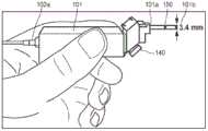
如图1A和图1B所示,多光子光学探针100包括轴向微机电系统(MEMS)扫描单元或台130、横向(MEMS)扫描单元或台140,以及远端光学器件150。横向扫描单元140适于通过移动横向镜组件在样品103的平面扫描区域上扫描输出激光能量,并且轴向扫描单元130联接到轴向镜组件并且适于在样品的深度范围内扫描输出激光能量。深度范围和平面扫描区域组合以形成三维体积。如将讨论的,轴向扫描单元包括围绕轴向镜组件轴向地定位的任何数量的致动腿。轴向扫描单元130、横向扫描单元140和远端光学器件150都通过光缆线缆102a、102b光联接到激光器和光收集电子器件(如任何数量的多模光纤、光电倍增管等,未示出)。任何数量的这些部件可至少部分地设置在单个手持式探针壳体框架101中。探针壳体框架101可包括近端101a和定位在样品103处的远端101b,并适于产生输出激光能量。As shown in FIGS. 1A and 1B , multiphoton
图2提供探针100的更详细的图示,其使用远程轴向扫描架构,其中利用在物镜处镜像的轴向扫描器平移在远端光学器件之前执行轴向和横向扫描。这类架构可支持具有紧凑的手持形状因子的小直径远端光学器件。在此方法中,通过静电旋转扫描镜执行横向扫描。FIG. 2 provides a more detailed illustration of
轴向扫描单元130和横向扫描单元140中的每一个可采用静电致动设计,和使用参数共振进行操作的设计。在本文所述的一些实例中,经由轴向扫描单元130的致动通过压电(PZT)致动器实现,所述致动器被组装或形成到安装夹具上,其中致动器被手动定位以消除扫描镜的任何静态轴外倾斜。每个致动器包括在轴向扫描或横向扫描物镜之前放置的镜或镜表面。Each of the
先前提及的激光器和光收集电子器件可包括具有大约690至1040nm的可调光谱范围的Ti-蓝宝石激光器104。此激光器104在80MHz下提供具有大约100fs脉冲宽度的激发105。可使用位于激光器壳体内部的色散预补偿单元来最小化脉冲持续时间。半波片106与线性偏振器107一起使用以调节激光功率。在通过偏振分束器(PBS)108之后,光束最初是p偏振的。在通过四分之一波片(QWP)109、从横向扫描单元140的横向扫描镜110(M1)反射,并通过QWP 109后,光束变为s偏振。The previously mentioned laser and light collection electronics may include a Ti-
在以90°从PBS 108反射之后,激发光束通过焦距为大约35mm的第一透镜111(L1)和焦距为大约100mm的第二透镜112(L2)扩展以填充第一物镜113的后孔径。第二PBS 114将光束通过QWP 116反射到轴向扫描镜115(M2)上。波前然后通过QWP 116和PBS 114返回,然后由两者都具有75mm的焦距的一对望远镜透镜117(L3)和118(L4)扩展。然后,光束以90°从二向色镜119(DM)反射,并填充第二物镜120(Obj2)的后孔径,在此实例中,所述第二物镜120是水浸透镜。随着轴向MEMS扫描单元130的轴向扫描镜115的表面在轴向方向上移动。M2115的平移引起焦点在放大率小于约2:1比率的样本的组织表面下方轴向位移。After reflection from the
如图2中所示,由样品103生成的荧光122通过DM 119、从平面镜123(M3)反射,并且通过具有60mm的焦距的第一透镜124(L5)和具有35mm的焦距的第二透镜125(L6)聚焦,并通过带通滤波器126(BPF;在大约380-580nm之间的大约80%的透射率),并且聚焦到光电倍增管检测器(PMT)127上。光电倍增管信号由高速电流放大器(未示出)放大。高速数据采集板将来自光电倍增器的荧光信号数字化并生成控制信号以驱动轴向扫描单元130和横向扫描单元140。在一些实例中,可将不同的、优化的驱动信号发送到各个镜和/或致动腿。第一板用于信号采集,并且第二板用于控制波形生成,使用定制软件的个人计算机可用于控制和同步数据采集板。来自信号采集板的通道可用于数字化具有期望采样率(例如,每秒10M样品)的电压信号。可在波形生成板中使用任意数量的通道(例如,三个)来生成具有期望采样速度(例如,每秒1M样品)的波形,以控制三个扫描轴。为了将一维数字化信号映射到2D图像,重要的是确保信号采集和波形生成精确同步。可在两个板之间使用实时系统集成(RTSI)线缆,使得它们可共享相同的定时源并且开始触发以保持同步。定制软件在Labview中写入,用于计算控制波形并将数据发送到波形生成板,同时从信号采集板读取数据。软件还可选择针对水平成像模式仅致动横向扫描器,或针对垂直成像模式致动横向和轴向扫描器。通过致动两个扫描单元140、130的不同轴,可在样品中的水平(XY)和垂直(XZ)平面之间改变扫描方向。As shown in FIG. 2,
基于参数共振原理,提供不同的静电MEMS扫描器用于横向和轴向扫描。大机械致动可通过以2ω0/n驱动结构来实现,其中ω0是扫描器的固有频率,并且n是≥1的整数。图3A示出形成为横向扫描单元140的横向致动器系统140a的零件的镜110。虽然镜110可采用不同的形状,但是在所示的实例中,镜110是圆形镜。在所示的实例中,直径为1.8mm并且镜110能够适应垂直入射(与45°相反)的宽度为1.27mm宽度的激发光束。横向致动器系统140a的前侧用铝涂布,以在大约200至900nm波长之间实现大于大约85%的反射率,以反射多光子激发的波长范围。Based on the principle of parametric resonance, different electrostatic MEMS scanners are offered for transverse and axial scanning. Large mechanical actuation can be achieved by driving the structure at 2ω0 /n, where ω0 is the natural frequency of the scanner and n is an integer > 1. FIG. 3A shows
在所示的实例中,横向致动器系统140a包括两个致动轴,镜110可围绕所述两个致动轴独立地旋转。如图所示定义X轴,所述X轴与内镜致动器的内腿或弹簧构件对准。Y轴被定义为与外镜致动器的外腿对准。每条腿分别是内和外梳状滤波器驱动器的零件。梳状滤波器驱动器提供静电致动,使得当由驱动信号驱动时,镜110分别围绕轴(X轴)和外轴(Y轴)旋转。内和外梳状滤波器驱动器中的每一个分别可以共振频率(例如,被选择在大约1kHz和大约4kHz之间的共振频率)操作。此外,可利用到每个梳状驱动器的选择的共振频率驱动信号驱动系统140a,使得镜110经历正弦扫描图案。在一个实例中,系统140a由共振频率驱动,以使用Lissajous扫描图案、并以每帧400×400像素扫描以≥5帧/秒成像。In the example shown,
横向致动器系统140a的内轴和外轴都可被致动以在水平(XY)平面中成像。这些轴的共振频率分别被设计为大约1kHz或4kHz。进一步地,通过组合横向扫描器的内轴的致动和轴向扫描器的平面外运动,可在垂直(XZ)平面中产生图像。当扫描对象时,形成密集的Lissajous扫描图案,所述图案以每秒5帧重复自身,以生成尺寸为400×400像素或400×320像素、100%覆盖的水平或垂直图像。MEMS扫描器通过LabView开发的定制软件驱动,所述软件还通过使用来自扫描器的校准运动轮廓将时间序列信号重新映射到2D图像以生成查找表来重建图像。换句话说,通过知道激光在特定时间被导引的位置,可映射返回激光的强度以形成2D图像。通过将轴向致动器安装在机动台上以精确地控制位置来量化轴向致动器系统130的位移与样本103中的焦点之间的关系。有利地,与传统成像装置相比,可以大约每秒5帧收集垂直区部,所述传统成像装置可需要几分钟来获取水平区部的堆叠并重建对应的垂直区部。Both the inner and outer axes of the
横向致动器系统140a可形成在尺寸为3×3mm2的芯片上。镜110安装在万向节框架141上,以最小化轴之间(即内轴和外轴驱动之间)的串扰。横向致动器系统140a以增加的共振频率操作,以便以较高的帧速率扫描。静电梳状驱动致动器145a、145b的正交组联接到内和外扭转腿或弹簧144a、144b,并基于它们的形状和配置确定扫描器的共振频率。图3B和图3C分别示出横向MEMS扫描器140在任一轴上的测量角度偏转,作为扫描器对于横向(即,水平)X轴和Y轴的60Vpp的正弦波输入的频率响应。可通过下扫描或上扫描来实现大扫描角度,但是通过下扫描可实现较大的偏转角度。对于X轴和Y轴两者,在所示的实例中,横向扫描器140可在60Vpp下利用接近8.2kHz和2kHz的驱动频率实现>5°的机械扫描角度。使用8570Hz和2100Hz的驱动频率分别在X轴和Y轴上产生4285Hz和1050Hz的实际倾斜频率。结果是密集的Lissajous扫描图案,所述图案以5Hz重复本身以针对250×250μm2的FOV涵盖尺寸为400×400像素具有100%覆盖的图像。The
在一些实例中,控制系统可被配置为实现Lissajous扫描。由于致动器运动均匀性增加,如果轴向镜扫描频率太接近横向镜扫描频率,则使用Lissajous扫描。通过调整轴向致动器设计以在特定频率下操作,获得快速Lissajous帧速率。In some examples, the control system can be configured to implement Lissajous scanning. Due to the increased uniformity of actuator motion, Lissajous scanning is used if the axial mirror scan frequency is too close to the transverse mirror scan frequency. Fast Lissajous frame rates are obtained by tuning the axial actuator design to operate at a specific frequency.
现在参照图4A至图9讨论轴向扫描单元130,特别是轴向致动器系统130a的细节。一维共振MEMS扫描器沿光轴在50V处具有大于约400μm的平面外(轴向)平移,以在垂直于组织表面的平面中产生图像。该位移将在样本下方提供超过大约200μm的轴向位移,这足以通过上皮层成像。直径为2mm的圆形轴向扫描镜(或反射器)115附接到镜平台132上,并通过位于每个拐角的蛇形弹簧134附接在两个U形杆133上。四列静电梳状驱动致动器(例如,梳状驱动器135)设置在镜115的每一侧上,以在每个杆上提供大的驱动力,这引起杆133绕Y轴的旋转运动。使两个杆133同相旋转引起圆形镜115的平面外位移。然而,当两个杆133异相时,镜115绕Y轴旋转。因此,当期望从另外稳定的平面镜进行轴向扫描(即,沿Z轴)时,将同相驱动信号提供给两个不同的梳状驱动器135。当期望组合的轴向扫描和旋转扫描时,将使用异相驱动信号或同相和异相驱动信号的某种组合。蛇形弹簧134确定每个梳状驱动器135的共振频率,并且它们确定每个扫描模式(即轴向(或垂直)扫描模式和旋转扫描模式)的共振频率。弹簧134被设计成增加垂直和旋转模式之间的频率间隔,以避免在致动期间的串扰。在实例中,对于垂直运动,共振频率为大约500Hz。Details of the
为了提供清晰的图像,轴向扫描镜115定位在与物镜120处的工作距离相同的轴向距离处,并保持对准,使得镜115的垂直轴沿着与透镜相同的轴和激光路径。这类对准依赖于镜115的水平对准,使得激光在其上居中。To provide a sharp image, the
对于轴向扫描镜115,频率响应通过使用激光位移传感器测量平面外位移表征。通过使用频率上扫描(低到高)或下扫描(高到低)以各种电压和占空比来扫描施加到致动器的驱动频率来测量扫描器性能。For the
与横向扫描单元140类似,轴向扫描单元130可形成在尺寸为3.7×3.2mm2的芯片上;并且镜115的直径为大约2mm。如图4B所示,通过使用60Vpp方波以30%占空比扫描在870Hz和1000Hz之间的驱动频率来示出轴向扫描单元130的频率响应。与横向扫描单元140不同,轴向扫描单元130在上扫描期间具有较大的位移。对于成像,扫描器以930Hz的驱动频率致动,从而引起在930Hz的驱动频率下多于400μm的轴向位移,这根据参数共振效应引起在465Hz下的致动。注意,轴向扫描单元130的共振频率在与横向扫描单元140不同的频率范围内,这允许对每种扫描模态进行更好的个性化控制。Similar to the
在一些实例中,可观察到由于弹簧中的软化效应引起的上扫描与下扫描的镜偏转幅度的相当大的差异。在离静止镜位置更远的距离处,静电力减小,这可引起具有两个稳定模式的动态分叉。一个这类节点出现在原点处,并且第二个节点出现在产生大偏转的稳定极限循环处。当从较高频率接近时(例如,在下扫描期间),可观察到最大的偏转,这是由于来自在此方向上倾斜的软化共振峰的振荡幅度逐渐增加。当从较低频率接近时(例如,在上扫描期间),原点保持在稳定的分叉分支处,直到上扫描和下扫描响应收敛的点。在一些实例中,轴向扫描单元130可出现相反的效果。In some instances, considerable differences in mirror deflection amplitudes for upscans and downscans due to softening effects in the springs can be observed. At greater distances from the stationary mirror position, the electrostatic force decreases, which can induce a dynamic bifurcation with two stable modes. One such node occurs at the origin, and a second node occurs at the limit cycle of stability that produces large deflections. The greatest deflection is observed when approaching from a higher frequency (eg, during a downscan), due to the progressive increase in oscillation amplitude from the softened formant tilted in this direction. When approached from lower frequencies (eg, during an upsweep), the origin remains at the stable bifurcated branch until the point where the upsweep and downsweep responses converge. In some instances, the
如图4C和图4D所示,轴向MEMS扫描单元130被提供在激光位移传感器(未示出)下方,所述激光位移传感器在施加驱动信号之前和之后生成所示的激光束斑点139。As shown in FIGS. 4C and 4D , the axial
如图4E至图4G所示,激发光束的波前随着轴向镜115的镜表面在任一方向上远离图4E所示的中性位置(ZM2=0μm)移动而改变。当镜115距第一物镜113200μm(ZM2=-200μm)时,波前会聚到第二物镜120上,并且焦平面朝向组织表面移动大约100μm,如图4F所示。类似地,当镜115移动靠近第一物镜113(ZM2=200μm)时,波前发散,并且焦平面以较大的深度轴向地移动到组织中,如图4G所示。As shown in FIGS. 4E-4G , the wavefront of the excitation beam changes as the mirror surface of the
如果轴向扫描镜115的镜表面在平移期间倾斜,则激发光束可变得未对准。因此,位置感测检测器(PSD)用于在轴向位移期间在驱动频率范围内测量围绕X轴和Y轴的倾斜角。当以930Hz驱动镜时,在X轴上测量最大倾斜角<0.004°(参见图4H),并且在Y轴上测量最大倾斜角<0.19°(参见图4I)。在小于大约1200Hz的频率下观察到此扫描器的旋转模式,这超出了致动器的操作范围。这些结果说明,在X轴或Y轴上以非常小的倾斜角可实现Z轴的大的轴向扫描位移。此外,通过适当地设计弹簧参数和位置,可为轴向扫描单元130分离轴向扫描和旋转(即,倾斜)扫描模式之间的频率范围。这类高性能轴向(即垂直)扫描器可使用功率变化小于10%的远程扫描设置实现轴向光束扫描。If the mirror surface of the
如图4J所示,在焦平面的位置和轴向MEMS镜115的位置之间观察到线性关系。由FWHM限定的轴向分辨率在镜114的扫描范围内从4.5μm到7μm变化,如图4K所示。利用在中间位置的镜115,测量270×270μm2的横向FOV。在平移镜115时,随着焦平面从中性位置从-100μm移动到100μm,横向放大率从大约1.2减小到0.9,并且横向FOV从320μm减小到240μm。此差异是由第一物镜113和第二物镜120之间的光学参数的轻微不匹配引起的,所述第一物镜113和第二物镜120分别是空气和水浸透镜。As shown in FIG. 4J , a linear relationship is observed between the position of the focal plane and the position of the
使用薄膜压电致动的轴向致动器系统530a的实例布置在图5至图9中提供,并且包括硅框架531、镜515设置在其上的镜平台532、提供驱动力的多个致动器腿535,以及用于电联接的多个接合垫537。应理解,轴向致动器系统530a可包括用于正确操作的任何数量的附加部件。在此实例布置中,部件,特别是腿535围绕镜平台532以圆形阵列分布。在一些实例中,腿535中的每一个可从镜平台532的中点等距分布,而在其它实例中,任何数量的腿535可以与镜平台532不同的长度分布。腿535以圆形阵列分布,以在腿535被致动时增强镜平台的稳定性,从而减少成像期间伪影的发生。换句话说,腿535可配对,使得成对的腿535位于镜的相对侧上并且在径向方向上延伸大约180度。然而,在一些实例中,腿535的三个均匀间隔的组可围绕镜平台532以彼此远离大约60度的角度设置。其它实例也是可能的。腿可在外支撑结构处附接到硅框架531并且可附接到镜平台532。压电层和电极层在硅框架531的顶部上延伸。通常,压电层重叠的区域用金或其它金属层加强。在一些实例中,厚聚合物涂层用作加强物。An example arrangement of an
在这些实例中的一些中,腿535被配置为将对称压电力施加到镜平台532。换句话说,镜平台532上的力的强度可均匀地分布在腿535之间。举例来说,如果一对腿535与镜平台532等距离地设置,则每个单独的腿535可适于向镜平台532施加相等的力。相反地,如果一对腿535与镜平台532不等距,则两个腿535中的一个可施加比另一个腿535更大的力,以便在镜平台532上施加组合的对称压电力。应当理解,任何数量的致动器腿535可协作以施加对称的压电力。In some of these examples,
腿535中的每个可包括协作以生成镜平台532的轴向移动的任何数量的单独区部。各个区部可在水平平面中以回转(或蛇形)图案配置,由此在相邻端部处彼此连接的扭转区段产生围绕连接点的延伸。Each of
在所示的实例中,多个铝垫设置在致动器腿535的顶部电极和底部电极上。由于这些部件的尺寸小,可难以在致动器腿和接合垫537之间形成强电连接。聚对二甲苯桥和其它材料层沉积在致动器腿535上,以产生从PZT膜的顶部和底部电极到接合垫537的电跳线或连接件。In the example shown, a plurality of aluminum pads are disposed on the top and bottom electrodes of the
另外,任何数量的致动器腿535可具有与其联接的任何数量的压阻传感器,以提供垂直位置的精确测量。如前所述,这种光学布置依赖于轴向扫描器的均匀垂直运动。传感器提供反馈机制,用于调节各个腿的电压,以平衡垂直运动并提供更均匀的运动。在一些实例中,传感器可提供反馈以使用闭环控制系统控制致动器。Additionally, any number of
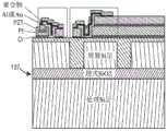
如图10和11A-G所示,致动器由具有30μm装置层的绝缘体上硅晶片制成。首先,通过深反应离子蚀刻(DRIE)将窄沟槽蚀刻到埋式氧化物层,并通过原硅酸四乙酯(TEOS)化学气相沉积(CVD)二氧化硅再填充(图11A)。晶片的顶部表面经过化学机械抛光,并涂布有为PZT沉积提供均匀的基层的附加的高温低压化学气相沉积(LPCVD)二氧化硅。通过此步骤产生的装置层中的隔离结构成为精确定义的完整平台(如框架和镜平台)的刚性硅元件。As shown in Figures 10 and 11A-G, the actuator was fabricated from a silicon-on-insulator wafer with a 30 μm device layer. First, narrow trenches are etched into the buried oxide layer by deep reactive ion etching (DRIE) and refilled by tetraethylorthosilicate (TEOS) chemical vapor deposition (CVD) silicon dioxide (FIG. 11A). The top surface of the wafer was chemical mechanically polished and coated with additional high temperature low pressure chemical vapor deposited (LPCVD) silicon dioxide to provide a uniform base layer for PZT deposition. The isolated structures in the device layers produced by this step become rigid silicon elements of precisely defined complete platforms such as frames and mirror platforms.
接下来,在制备的晶片上沉积底电极(Ti/Pt,200nm)、压电(PNZT晶种/化学溶液PZT,1.2μm)和顶部电极(Pt,120nm),并通过反应离子蚀刻(RIE)依次图案化。如图11B所示,然后通过剥离工艺将结构铝层(1μm)图案化到电极的选定区域的顶部表面,以改善接合垫强度并调节悬臂梁的下弯部分的中性轴。如前所述并如图10和图11C所示,为了提高电互连的可靠性,沉积聚对二甲苯-C膜(560nm)、二氧化硅(230nm)层和附加铝层(1μm)以产生从PZT膜的顶部和底部电极到直接在二氧化硅晶片表面上图案化的接合垫的电跳线,其对于在内窥显微镜仪器的受限空间中所需的引线接合具有明显更好的可靠性。Next, the bottom electrode (Ti/Pt, 200nm), the piezoelectric (PNZT seed/chemical solution PZT, 1.2μm) and the top electrode (Pt, 120nm) were deposited on the prepared wafer and processed by reactive ion etching (RIE) sequentially patterned. As shown in FIG. 11B , a structural aluminum layer (1 μm) was then patterned onto the top surface of selected regions of the electrodes by a lift-off process to improve bonding pad strength and tune the neutral axis of the downturned portion of the cantilever beam. As previously described and shown in Figures 10 and 11C, in order to improve the reliability of electrical interconnections, a parylene-C film (560nm), a silicon dioxide (230nm) layer and an additional aluminum layer (1μm) were deposited to produced electrical jumpers from the top and bottom electrodes of the PZT film to bond pads patterned directly on the silicon dioxide wafer surface, which is significantly better for wire bonding required in the confined space of endoscopic microscope instruments reliability.
使用一系列深沟槽蚀刻步骤从硅晶片释放致动器腿535。首先,如图11D所示,执行硅DRIE和二氧化硅RIE步骤以蚀刻穿过致动腿之间的埋式氧化物。接下来,执行两级背面DRIE,其中在各个致动器腿下方进行初始蚀刻(图11E),然后在所有运动零件下方进行完全背面区域蚀刻(图11F)。通过在完成背面DRIE工艺之前蚀刻最初由背面蚀刻的较深部分暴露的二氧化硅层,可释放独立的薄膜PZT梁元件,同时保留固体硅平台作为镜平台或镜本身(图11G)。在此最后的释放步骤期间,由于在较早步骤中形成的二氧化硅填充的沟槽(图11A),可利用SF6或XeF2蚀刻来处理硅的不均匀蚀刻或微柱的形成。利用优化的蚀刻参数和层厚度,可省略装置层中的保护性二氧化硅沟槽(图11A)的形成。The
两个光子激发的荧光强度与焦点处的光子通量具有非线性关系,因此当轴向扫描单元130在平面外时激光强度必须是稳定的。在致动器系统130a的制作中,DRIE和其它过程可引起腿的结构不对称。因此,大的平面外运动可引起镜表面产生小的倾斜角,并因此可使光束散焦。为了确定倾斜角如何影响成像,执行光线跟踪模拟。开发了具有近轴透镜的模型,所述模型具有与透镜113和120相同的焦距。当镜扫描时,轴向扫描单元130在不同的轴向位置处并且以不同的倾斜角使用点扩散函数。轴向点扩散函数的峰强度可用作评估焦点处激光功率变化的度量。The fluorescence intensity excited by two photons has a nonlinear relationship with the photon flux at the focal point, so the laser intensity must be stable when the
使用此模型,可确定轴向MEMS扫描器130所需的轴向位移和镜尺寸。此信息可用于设计MEMS扫描器的参数,以便实现在轴向扫描期间峰强度变化小于10%的水平或垂直平面中的250×250μm2的视野。Using this model, the axial displacement and mirror dimensions required for the
为了证明轴向MEMS扫描器130的性能,在XY和XZ平面中成像直径为大约30至40μm的自发荧光花粉。通过以1μm步长在轴向方向上移动样品50μm来获得在水平(XY)平面收集的图像的3D堆叠。然后重建垂直投影(XZ)并与利用轴向扫描器在垂直平面(XZ)中收集的图像进行比较。To demonstrate the performance of the
根据模拟结果,轴向扫描单元130的位移和焦斑具有大约1:1的放大率。示出在倾斜角为0°、0.8°和1.6°的情况下,轴向扫描器在Z轴中100μm上位移(图12A-C)或100μm下位移(图12D-F)的点扩散函数的变化的结果。对于模拟结果,倾斜角小至1.6°可将峰强度降低20%以上。According to the simulation results, the displacement of the
转到图13A-C,图13A是在水平扫描模式下的花粉的XY图像,其中视野为100×100μm2。收集水平图像,同时以50μm的增量轴向地移动样本。从随后的3D重建中提取垂直图像,如图13B所示。相比之下,我们通过平移图13C中的镜115直接在垂直平面中收集图像,两种类型的XZ图像的视野都为100×50μm2。在这两种类型的垂直图像之间没有观察到明显的分辨率或强度变化。换句话说,无论是否执行XY或XZ扫描,都可看到作为成像深度的函数的相同强度的返回光。Turning to Figures 13A-C, Figure 13A is an XY image of pollen in horizontal scan mode with a field of view of 100 x 100 μm2 . Horizontal images were collected while moving the sample axially in 50 μm increments. A vertical image is extracted from the subsequent 3D reconstruction, as shown in Figure 13B. In contrast, we collect images directly in the vertical plane by translating the
图14A是示出不同的隐窝结构的在水平(XY)平面上在270×270μm2的FOV中获得的样本的代表性图像。可区分六边形包装的圆形隐窝(如箭头所示),其具有围绕中心内腔(l)的均匀尺寸。在细胞质(c)中可看到粘蛋白填充的杯状细胞(g),其产生均匀的荧光。可在固有层(lp)中识别个体炎性细胞(箭头)。图14B是在相同的位置的视野为270×200μm2的XZ图像。内腔(1)现在垂直取向,并且看到杯状(g)细胞在顶端到基底方向上分布。FIG. 14A is a representative image of a sample acquired in a FOV of 270×270 μm2 in the horizontal (XY) plane showing different crypt structures. Hexagonally packed circular crypts can be distinguished (indicated by arrows) with uniform dimensions surrounding a central lumen (l). Mucin-filled goblet cells (g) that produce uniform fluorescence are seen in the cytoplasm (c). Individual inflammatory cells (arrowheads) can be identified in the lamina propria (lp). Figure 14B is an XZ image of the same position with a field of view of 270 x 200 μm2 . The lumen (1) is now vertically oriented and goblet (g) cells are seen distributed in an apical to basal direction.
图15至图16D示出轴向致动器系统630a的替代设计。替代设计可在硅晶片上适应附加的方形致动器。中心镜或镜平台632由四个蛇形压电弯曲梁、腿或致动器635支撑,其中压电堆叠材料变化以在梁635的连续区段中产生选择性上弯或下弯运动。这引起镜表面632的明确限定的垂直平移在理想条件下通过结构的对称性进一步增强。15-16D show an alternative design of the
轴向致动器系统630a具有用于最终集成到5mm直径或更小的内窥显微镜仪器中的大约3mm×3mm×0.5mm的总尺寸,以及致动器635设计,所述设计包括四个1.2mm长的单独光束以产生沿光轴的约400μm的垂直(即,平面外)位移,以利用约100Hz的固有频率在垂直于组织表面的平面中产生图像。致动器635在近共振下操作,其中Lissajous扫描用于从垂直压电致动器和面内静电扫描镜的组合运动中提取图像。使用共振操作可在低电压下实现大扫描范围,以及镜的动态平衡,以用于均匀的垂直运动,即使只有单个输入到四个驱动腿。The
前面的描述证明了一种新颖的多光子显微镜,所述多光子显微镜使用远程扫描配置和MEMS扫描器来提供实时可切换的XY/XZ成像。轴向MEMS扫描器以大约440Hz的机械共振频率在共振模式下工作,产生200um范围的880Hz的线扫描速率。这种高速轴向扫描技术可用于研究快速生物过程,如活体动物中神经元之间的动作电位。虽然超快脉冲聚焦在轴向MEMS上,但在50mW激光功率下暴露一小时后,没有观察到镜表面损坏的迹象。通过将镜涂层从铝改变为金,可进一步提高损伤阈值。横向MEMS扫描器也以内轴和外轴的共振频率为大约4kHz和1kHz在共振模式下工作。Lissajous扫描用于FOV分别为250μm×250μm和250μm×200μm、帧速率为5Hz的水平或垂直平面成像。这些MEMS扫描器非常紧凑,占地面积为约3mm×3mm,同时维持良好的机械性能。它们还具有高可靠性、低成本且易于批量生产。这些MEMS扫描器可以是传统显微镜中使用的大型致动器的良好替代物。通过使用这种扫描策略,可开发出具有实时水平和垂直切片功能的超紧凑型活体显微镜,或甚至微型装置。另外,在一些系统中,可在具有与本文所述的轴向扫描致动器类似的几何形状的布置中使用电热、电磁和/或其它微致动器,或使用具有偏移电极的静电致动器来实现低频(DC)扫描来完成轴向扫描。The foregoing description demonstrates a novel multiphoton microscope that uses a remote scanning configuration and a MEMS scanner to provide real-time switchable XY/XZ imaging. The axial MEMS scanner operates in resonant mode with a mechanical resonance frequency of approximately 440Hz, yielding a line scan rate of 880Hz in the 200um range. This high-speed axial scanning technique can be used to study fast biological processes such as action potentials between neurons in living animals. Although the ultrafast pulses were focused on the axial MEMS, no signs of mirror surface damage were observed after one hour of exposure to 50 mW laser power. The damage threshold can be further increased by changing the mirror coating from aluminum to gold. The transverse MEMS scanner also operates in resonant mode with resonant frequencies of about 4 kHz and 1 kHz for the inner and outer shafts. Lissajous scans were used for horizontal or vertical plane imaging with FOVs of 250 μm × 250 μm and 250 μm × 200 μm, respectively, and a frame rate of 5 Hz. These MEMS scanners are very compact, with a footprint of about 3mm x 3mm, while maintaining good mechanical properties. They are also highly reliable, low cost and easy to mass produce. These MEMS scanners could be good replacements for the large actuators used in conventional microscopes. By using this scanning strategy, ultra-compact intravital microscopes, or even miniaturized devices, with real-time horizontal and vertical sectioning capabilities can be developed. Additionally, in some systems, electrothermal, electromagnetic, and/or other microactuators may be used in arrangements with similar geometries to the axial scanning actuators described herein, or using electrostatically actuated The actuator is used to realize low-frequency (DC) scanning to complete the axial scanning.
在依赖于弯曲梁架构的大位移垂直台中,中心台运动可对各个腿中的不对称非常敏感,这可以是由于残余应力的局部变化、光刻未对准或其它加工非理想性造成的。处理非均匀中心台运动的一种方式是通过向两个或更多个腿施加不同的电压来校准和补偿不对称性。通过识别多个振动模式的贡献产生几乎纯垂直平移的频率,可实现均匀的垂直运动,从而允许仅通过输入到台的电压来执行平衡。In large-displacement vertical stages relying on curved beam architecture, center stage motion can be very sensitive to asymmetries in the individual legs, which can be due to local variations in residual stress, lithographic misalignment, or other processing non-idealities. One way to deal with non-uniform center table motion is to calibrate and compensate for the asymmetry by applying different voltages to the two or more legs. Uniform vertical motion is achieved by identifying frequencies at which the contribution of multiple vibrational modes produces almost pure vertical translation, allowing balancing to be performed solely by the voltage input to the stage.
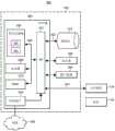
图17是示出用于实施本文所讨论的薄膜压电多光子内窥显微镜802的实例实施例的各种部件的实例框图800。本文先前讨论的光学器件150可根据执行所公开实施例的功能而定位在样本103附近或可操作地联接到样本103。装置802可具有控制器804,所述控制器804经由连接到输入/输出(I/O)电路812的链路822可操作地连接到数据库814。应当注意,虽然未示出,但是可以已知的方式将附加数据库链接到控制器804。控制器804包括程序存储器806、处理器808(可称为微控制器或微处理器)、随机存取存储器(RAM)810和输入/输出(I/O)电路812,所有这些都是通过地址/数据总线820互连。应当理解,尽管仅示出了一个微处理器808,但是控制器804可包括多个微处理器808。类似地,控制器804的存储器可包括多个RAM 810和多个程序存储器806。尽管I/O电路812被示出为单个块,但是应当理解,I/O电路812可包括许多不同类型的I/O电路。举例来说,RAM 810和程序存储器806可被实施为半导体存储器、磁性可读存储器和/或光学可读存储器。链路824可通过I/O电路812将控制器804可操作地连接到光学器件150。17 is an example block diagram 800 illustrating various components for implementing an example embodiment of a thin-film
程序存储器806和/或RAM 810可存储由微处理器808执行的各种应用程序(即,机器可读指令)。举例来说,操作系统830通常可控制内窥显微镜802的操作并向测试设备提供用户界面以实施本文描述的过程。程序存储器806和/或RAM 810还可存储用于访问内窥显微镜802的特定功能的各种子例程832。作为实例而非限制,子例程832可尤其包括:用于控制如本文所述的光学装置150或其它内窥镜装置的操作的子例程;用于利用如本文所述的光学器件150捕获图像的子例程;和其它子例程,例如,实施软件键盘功能、与内窥显微镜802中的其它硬件交接的子例程等。程序存储器806和/或RAM 810还可存储与内窥显微镜802的配置和/或操作有关、和/或与一个或多个子例程的操作有关的数据。举例来说,数据可以是由光学器件150收集的数据、由处理器808确定和/或计算的数据等。除了控制器804之外,内窥显微镜802还可包括其它硬件资源。内窥显微镜802还可联接到各种类型的输入/输出硬件,如视觉显示器826和(一个或多个)输入装置828(例如,小键盘、键盘等),以微调轴向和横向扫描器的致动。在实施例中,显示器826是触敏的,并且可与软件键盘例程协作作为软件例程832中的一个以接受用户输入。
在整个本说明书中,多个示例可实施被描述为单个示例的部件、操作或结构。尽管一个或多个方法的各个操作被示出并描述为单独的操作,但是可同时执行单独的操作中的一个或多个,并且不需要以所示的顺序执行操作。在实例配置中作为单独部件呈现的结构和功能可被实施为组合结构或部件。类似地,作为单个部件呈现的结构和功能可被实施为单独的部件。这些和其它变化、修改、添加和改进都落入本文主题的范围内。Throughout this specification, multiple examples may implement a component, operation, or structure that is described as a single example. Although individual operations of one or more methods are shown and described as separate operations, one or more of the separate operations may be performed concurrently, and the operations do not need to be performed in the order shown. Structures and functionality presented as separate components in example configurations may be implemented as a combined structure or component. Similarly, structures and functionality presented as a single component may be implemented as separate components. These and other variations, modifications, additions and improvements are within the scope of the subject matter herein.
另外,本文将某些实施例描述为包括逻辑或许多例程,子例程、应用程序或指令。这些可构成软件(例如,在非暂时性机器可读介质上体现的代码)或硬件。在硬件中,例程等是能够执行某些操作的有形单元,并且可以某种方式配置或布置。在实例实施例中,一个或多个计算机系统(例如,独立的客户端或服务器计算机系统)或计算机系统的一个或多个硬件模块(例如,处理器或处理器组)可由软件(例如,应用程序或应用程序部分)配置为操作以执行如本文所述的某些操作的硬件模块。Additionally, certain embodiments are described herein as comprising logic or a number of routines, subroutines, applications or instructions. These may constitute software (eg, code embodied on a non-transitory machine-readable medium) or hardware. In hardware, a routine etc. is a tangible unit capable of performing certain operations and can be configured or arranged in a certain way. In an example embodiment, one or more computer systems (e.g., a stand-alone client or server computer system) or one or more hardware modules (e.g., a processor or groups of processors) of a computer system may be controlled by software (e.g., an application program or application portion) as a hardware module configured to operate to perform certain operations as described herein.
在各种实施例中,硬件模块可机械地或电子地实施。举例来说,硬件模块可包含永久配置的专用电路或逻辑(例如,作为专用处理器,如现场可编程门阵列(FPGA)或专用集成电路(ASIC))以执行某些操作。硬件模块还可包含由软件临时配置以执行某些操作的可编程逻辑或电路(例如,包含在通用处理器或其它可编程处理器内)。应当理解,可通过成本和时间考虑来驱动机械地在专用和永久配置的电路中或在临时配置的电路中(例如,由软件配置)实施硬件模块的决定。In various embodiments, hardware modules may be implemented mechanically or electronically. For example, a hardware module may contain dedicated circuitry or logic permanently configured (eg, as a special purpose processor such as a field programmable gate array (FPGA) or an application specific integrated circuit (ASIC)) to perform certain operations. A hardware module may also contain programmable logic or circuitry that is temporarily configured by software to perform certain operations (eg, as included within a general-purpose processor or other programmable processor). It should be appreciated that the decision to implement hardware modules mechanically in dedicated and permanently configured circuitry or in temporarily configured circuitry (eg, configured by software) may be driven by cost and time considerations.
因此,术语“硬件模块”应该被理解为包含有形实体,即被物理构造、被永久配置(例如,硬连线)或被临时配置(例如,编程)为以某种方式操作或执行本文描述的某些操作的实体。考虑其中临时配置(例如,编程)硬件模块的实施例,不需要在任何一个时刻配置或实例化硬件模块中的每个。举例来说,在硬件模块包含使用软件配置的通用处理器的情况下,通用处理器可在不同时间被配置为相应的不同硬件模块。因此,软件可配置处理器,以例如在一个时刻构成特定硬件模块,并在不同时刻构成不同的硬件模块。Accordingly, the term "hardware module" should be understood to include tangible entities that are physically constructed, permanently configured (e.g., hardwired), or temporarily configured (e.g., programmed) to operate in a certain manner or perform the functions described herein. Entities for certain operations. Considering embodiments where hardware modules are temporarily configured (eg, programmed), each of the hardware modules need not be configured or instantiated at any one time. For example, where the hardware modules include a general-purpose processor configured using software, the general-purpose processor may be configured at different times as corresponding different hardware modules. Thus, software may configure a processor to, for example, constitute a particular hardware module at one time and a different hardware module at a different time.
硬件模块可向其它硬件模块提供信息并从其接收信息。因此,所描述的硬件模块可被视为通信地联接。在同时存在多个这类硬件模块的情况下,可通过连接硬件模块的信号传输(例如,通过适当的电路和总线)来实现通信。在其中在不同时间配置或实例化多个硬件模块的实施例中,可例如通过存储和检索多个硬件模块可访问的存储器结构中的信息来实现这类硬件模块之间的通信。举例来说,一个硬件模块可执行操作并将所述操作的输出存储在与其通信联接的存储器装置中。然后,另一硬件模块可稍后访问存储器装置以检索和处理存储的输出。硬件模块还可启动与输入或输出装置的通信,并且可对资源进行操作(例如,信息收集)。Hardware modules can provide information to, and receive information from, other hardware modules. Accordingly, the described hardware modules may be regarded as being communicatively coupled. Where multiple such hardware modules are present concurrently, communication may be accomplished by signal transmission (eg, through appropriate circuits and buses) connecting the hardware modules. In embodiments where multiple hardware modules are configured or instantiated at different times, communication between such hardware modules may be accomplished, for example, by storing and retrieving information in memory structures accessible by the multiple hardware modules. For example, a hardware module may perform operations and store the output of the operations in a memory device communicatively coupled thereto. Another hardware module can then later access the memory device to retrieve and process the stored output. A hardware module may also initiate communications with input or output devices, and may perform operations on resources (eg, information gathering).
本文中所描述的实例方法的各种操作可至少部分地由被临时配置(例如,通过软件)或被永久配置为执行相关操作的一个或多个处理器执行。无论是临时配置还是永久配置,这类处理器可构成操作以执行一个或多个操作或功能的处理器实施的模块。在一些实例实施例中,本文提及的模块可包含处理器实施的模块。Various operations of the example methods described herein may be performed, at least in part, by one or more processors that are temporarily configured (eg, by software) or permanently configured to perform the relevant operations. Whether temporarily configured or permanently configured, such processors may constitute processor-implemented modules operative to perform one or more operations or functions. In some example embodiments, the modules mentioned herein may include processor-implemented modules.
类似地,本文所描述的方法或例程可至少部分是处理器实施的。举例来说,方法的操作中的至少一些可通过一个或多个处理器或处理器实施的硬件模块执行。操作的特定性能可分布在不仅驻存在单一机器内,而且还跨越多个机器部署的一个或多个处理器当中。在一些实例实施例中,一个或多个处理器可位于单个位置中(例如,位于家庭环境、办公室环境或服务器集群内),而在其它实施例中,处理器可跨越多个位置分布。Similarly, the methods or routines described herein may be at least partially processor-implemented. For example, at least some of the operations of the methods may be performed by one or more processors or processor-implemented hardware modules. Specific performance of operations may be distributed among one or more processors not only residing within a single machine, but also deployed across multiple machines. In some example embodiments, one or more processors may be located in a single location (eg, within a home environment, office environment, or server cluster), while in other embodiments, the processors may be distributed across multiple locations.
操作的特定性能可分布在不仅驻存在单一机器内,而且还跨越多个机器部署的一个或多个处理器当中。在一些实例实施例中,一个或多个处理器或处理器实施的模块可位于单个地理位置中(例如,家庭环境、办公室环境或服务器集群内)。在其它实例实施例中,一个或多个处理器或处理器实施的模块可跨越多个地理位置分布。Specific performance of operations may be distributed among one or more processors not only residing within a single machine, but also deployed across multiple machines. In some example embodiments, one or more processors or processor-implemented modules may be located in a single geographic location (eg, within a home environment, office environment, or server cluster). In other example embodiments, one or more processors or processor-implemented modules may be distributed across multiple geographic locations.
除非另有特定说明,否则在本文中使用如“处理”、“运算”、“计算”、“确定”、“呈现”、“显示”等词的论述可指操控或变换一个或多个存储器(例如,易失性存储器、非易失性存储器或其组合)、寄存器或接收、存储、传输或显示信息的其它机器部件内的表示为物理(例如,电子、磁性或光学)量的数据的机器(例如,计算机)的动作或过程。Discussion herein using words such as "process," "operate," "compute," "determine," "render," "display," etc. may refer to manipulating or transforming one or more memories ( A machine representing data as physical (for example, electronic, magnetic, or optical) quantities within, for example, volatile memory, nonvolatile memory, or combinations thereof), registers, or other machine parts that receive, store, transmit, or display information An action or process (for example, a computer).
如本文所使用,对“一个实施例”或“实施例”的任何参考意味着结合实施例所描述的特定元件、特征、结构或特性包括于至少一个实施例中。短语“在一个实施例中”在说明书中的各处的出现不一定都指相同实施例。As used herein, any reference to "one embodiment" or "an embodiment" means that a particular element, feature, structure, or characteristic described in connection with the embodiment is included in at least one embodiment. The appearances of the phrase "in one embodiment" in various places in the specification are not necessarily all referring to the same embodiment.
可使用表达“联接”和“连接”以及它们的派生词来描述一些实施例。举例来说,可使用术语“联接”来描述一些实施例,以指示两个或更多个元件处于直接物理或电接触。然而,术语“联接”还可表示两个或更多个元件彼此不直接接触,但仍然彼此协作或交互。实施例不限于此上下文。Some embodiments may be described using the expressions "coupled" and "connected," along with their derivatives. For example, some embodiments may be described using the term "coupled" to indicate that two or more elements are in direct physical or electrical contact. However, the term "coupled" may also mean that two or more elements are not in direct contact with each other, but yet still co-operate or interact with each other. The embodiments are not limited in this context.
本领域的技术人员将认识到,在不脱离本发明的范围的情况下,可关于上述实施例作出各种修改、改变和组合,且这类修改、改变和组合被视为在本发明概念的范围内。Those skilled in the art will appreciate that various modifications, changes and combinations can be made with respect to the above-mentioned embodiments without departing from the scope of the present invention, and such modifications, changes and combinations are considered to be within the scope of the present invention. within range.
Claims (18)
Applications Claiming Priority (3)
| Application Number | Priority Date | Filing Date | Title |
|---|---|---|---|
| US201662429438P | 2016-12-02 | 2016-12-02 | |
| US62/429,438 | 2016-12-02 | ||
| PCT/US2017/064539WO2018102822A1 (en) | 2016-12-02 | 2017-12-04 | Multi-photon endomicroscope for vertical cross-sectional imaging |
Publications (2)
| Publication Number | Publication Date |
|---|---|
| CN110062603A CN110062603A (en) | 2019-07-26 |
| CN110062603Btrue CN110062603B (en) | 2023-06-16 |
Family
ID=62241911
Family Applications (1)
| Application Number | Title | Priority Date | Filing Date |
|---|---|---|---|
| CN201780074828.3AActiveCN110062603B (en) | 2016-12-02 | 2017-12-04 | Multiphoton endoscopic microscope for vertical cross-section imaging |
Country Status (3)
| Country | Link |
|---|---|
| US (1) | US11215805B2 (en) |
| CN (1) | CN110062603B (en) |
| WO (1) | WO2018102822A1 (en) |
Families Citing this family (10)
| Publication number | Priority date | Publication date | Assignee | Title |
|---|---|---|---|---|
| WO2018204674A1 (en)* | 2017-05-04 | 2018-11-08 | Massachusetts Institute Of Technology | Scanning optical imaging device |
| CN111095074B (en)* | 2017-07-24 | 2023-06-09 | 密歇根大学董事会 | 3-axis side-viewing confocal fluorescence microscopy |
| EP3941329B1 (en) | 2019-03-18 | 2024-04-10 | The Regents Of The University Of Michigan | Ultra-compact folded-beam path confocal endomicroscope |
| US12396625B2 (en) | 2019-03-18 | 2025-08-26 | The Regents Of The University Of Michigan | Ultra-compact microsystems-based single axis confocal endomicroscope |
| CN110464309B (en)* | 2019-08-27 | 2021-12-17 | 深圳大学 | Cross-scale fluorescence endoscopic imaging system |
| WO2021113711A1 (en)* | 2019-12-04 | 2021-06-10 | The Regents Of The University Of California | Multiphoton magnetic resonance imaging |
| CN112669226B (en)* | 2020-12-10 | 2023-09-05 | 香港理工大学深圳研究院 | Sweep frequency optical frequency comb coherent tomography virtual image elimination method |
| CN112485898A (en)* | 2020-12-15 | 2021-03-12 | 南京超维景生物科技有限公司 | Miniaturized multi-photon microscope system, probe thereof and control method |
| US20240197157A1 (en)* | 2022-12-20 | 2024-06-20 | Karl Storz Imaging, Inc. | Scene Adaptive Endoscopic Illuminator with Fluorescence Illumination |
| CN116250795A (en)* | 2023-02-03 | 2023-06-13 | 之江实验室 | Endoscope imaging system and sapphire protection window design method |
Family Cites Families (15)
| Publication number | Priority date | Publication date | Assignee | Title |
|---|---|---|---|---|
| US4478482A (en) | 1981-05-11 | 1984-10-23 | Koester Charles J | Axial scanning optical system and method of examining an object plane |
| US6157448A (en)* | 1999-10-08 | 2000-12-05 | Uniopt Co., Ltd. | Birefringence measurement optical system and high spatial resolution polarimetric apparatus |
| US7616986B2 (en)* | 2001-05-07 | 2009-11-10 | University Of Washington | Optical fiber scanner for performing multimodal optical imaging |
| US7336988B2 (en)* | 2001-08-08 | 2008-02-26 | Lucent Technologies Inc. | Multi-photon endoscopy |
| DE102006046555B4 (en) | 2006-09-28 | 2010-12-16 | Grintech Gmbh | Miniaturized optical imaging system with high lateral and axial resolution |
| JP2009063637A (en)* | 2007-09-04 | 2009-03-26 | Fujifilm Corp | Optical scanning probe, optical scanning probe device, and optical scanning probe control method |
| WO2011053828A2 (en)* | 2009-10-30 | 2011-05-05 | The Regents Of The University Of Michigan | Targeted dual-axes confocal imaging apparatus with vertical scanning capabilities |
| US8807801B2 (en)* | 2011-01-21 | 2014-08-19 | The Regents Of The University Of Michigan | Two-photon endoscopic scanning assembly for inflammatory disease detection |
| CA2850068A1 (en)* | 2011-09-27 | 2013-04-04 | British Columbia Cancer Agency Branch | Scanning optical systems |
| CN102445568B (en)* | 2011-10-10 | 2013-09-18 | 北京大学 | Ultrahigh vacuum four-probe scanning tunneling microscope for multi-probe common imaging |
| US9721326B2 (en)* | 2011-11-08 | 2017-08-01 | UNIVERSITé LAVAL | Method and system for improving resolution in laser imaging microscopy |
| CN102697483B (en)* | 2012-06-04 | 2014-07-09 | 凝辉(天津)科技有限责任公司 | Light-driven double-shaft optical scanning probe |
| US8902346B2 (en)* | 2012-10-23 | 2014-12-02 | Intersil Americas LLC | Systems and methods for controlling scanning mirrors for a display device |
| CN103054554B (en)* | 2012-12-29 | 2014-10-22 | 陈英俊 | Optical imaging device capable of deep scanning along axial direction and method and application thereof |
| CN103393392B (en)* | 2013-06-19 | 2015-08-26 | 西安电子科技大学 | The probe laser confocal micro endoscope of the degree of depth and intensity adjustable |
- 2017
- 2017-12-04CNCN201780074828.3Apatent/CN110062603B/enactiveActive
- 2017-12-04USUS16/465,558patent/US11215805B2/enactiveActive
- 2017-12-04WOPCT/US2017/064539patent/WO2018102822A1/ennot_activeCeased
Non-Patent Citations (1)
| Title |
|---|
| 多光子显微成像技术用于食管鳞癌进程监测的研究;徐健;中国优秀硕士学位论文全文数据库 医药卫生科技辑(第2期);第10-17页* |
Also Published As
| Publication number | Publication date |
|---|---|
| US20200096753A1 (en) | 2020-03-26 |
| US11215805B2 (en) | 2022-01-04 |
| WO2018102822A1 (en) | 2018-06-07 |
| CN110062603A (en) | 2019-07-26 |
Similar Documents
| Publication | Publication Date | Title |
|---|---|---|
| CN110062603B (en) | Multiphoton endoscopic microscope for vertical cross-section imaging | |
| Ra et al. | Two-dimensional MEMS scanner for dual-axes confocal microscopy | |
| Liu et al. | MEMS-based 3D confocal scanning microendoscope using MEMS scanners for both lateral and axial scan | |
| US8700134B2 (en) | Cantilever-based MEMS optical scanning apparatus, system and method | |
| Kaur et al. | Scanning and actuation techniques for cantilever-based fiber optic endoscopic scanners—a review | |
| US20120140302A1 (en) | Mems-based optical image scanning apparatus, methods, and systems | |
| US11534049B2 (en) | Image generating device | |
| US10642027B2 (en) | 3D MEMS scanner for real-time cross-sectional endomicroscopy | |
| Qiu et al. | MEMS-based medical endomicroscopes | |
| KR102555734B1 (en) | Image calibration algorithm based on lissajous scanning | |
| Piyawattanametha et al. | 3-D near-infrared fluorescence imaging using an MEMS-based miniature dual-axis confocal microscope | |
| Kumar et al. | Handheld histology-equivalent sectioning laser-scanning confocal optical microscope for interventional imaging | |
| US12396625B2 (en) | Ultra-compact microsystems-based single axis confocal endomicroscope | |
| Pan et al. | A MEMS mirror-based confocal laser endomicroscope with image distortion correction | |
| Mansoor et al. | A handheld electromagnetically actuated fiber optic raster scanner for reflectance confocal imaging of biological tissues | |
| Choi et al. | Multi-photon vertical cross-sectional imaging with a dynamically-balanced thin-film PZT z-axis microactuator | |
| Li et al. | An electrostatic MEMS scanner with in-plane and out-of-plane two-dimensional scanning capability for confocal endoscopic in vivo imaging | |
| Baranski | Optical design and developent of building blocks for a new generation of vertically integrated on-chip confocal microscopes | |
| Fan | A piezoelectric fiber scanner for reflectance confocal imaging of biological tissues | |
| Liu et al. | Fiber-optic confocal microscope with an electrothermally-actuated, large-tunable-range microlens scanner for depth scanning | |
| Piyawattanametha et al. | Three-dimensional in vivo real time imaging by a miniature dual-axes confocal microscope based on a two-dimensional MEMS scanner | |
| CN119744365A (en) | Three-dimensional two-photon micro microscope | |
| Bakas | Miniaturization of light-sheet microscopy systems using MEMS as active optical elements | |
| Chandrappan | Optical alignment of dual-axis MEMS based scanning optical probe for Optical Coherence Tomography (OCT) application | |
| Li et al. | Large Out-of-Plane Stroke for Remote Axial-Scanning in Multi-Photon Microscopy |
Legal Events
| Date | Code | Title | Description |
|---|---|---|---|
| PB01 | Publication | ||
| PB01 | Publication | ||
| SE01 | Entry into force of request for substantive examination | ||
| SE01 | Entry into force of request for substantive examination | ||
| GR01 | Patent grant | ||
| GR01 | Patent grant |