CN110035704B - Medical device for treating hard tissue and related methods - Google Patents
Medical device for treating hard tissue and related methodsDownload PDFInfo
- Publication number
- CN110035704B CN110035704BCN201780074191.8ACN201780074191ACN110035704BCN 110035704 BCN110035704 BCN 110035704BCN 201780074191 ACN201780074191 ACN 201780074191ACN 110035704 BCN110035704 BCN 110035704B
- Authority
- CN
- China
- Prior art keywords
- indicator
- medical device
- working end
- end portion
- distal
- Prior art date
- Legal status (The legal status is an assumption and is not a legal conclusion. Google has not performed a legal analysis and makes no representation as to the accuracy of the status listed.)
- Active
Links
Images


Classifications
- A—HUMAN NECESSITIES
- A61—MEDICAL OR VETERINARY SCIENCE; HYGIENE
- A61B—DIAGNOSIS; SURGERY; IDENTIFICATION
- A61B17/00—Surgical instruments, devices or methods
- A61B17/16—Instruments for performing osteoclasis; Drills or chisels for bones; Trepans
- A61B17/1613—Component parts
- A61B17/1631—Special drive shafts, e.g. flexible shafts
- A—HUMAN NECESSITIES
- A61—MEDICAL OR VETERINARY SCIENCE; HYGIENE
- A61B—DIAGNOSIS; SURGERY; IDENTIFICATION
- A61B17/00—Surgical instruments, devices or methods
- A61B17/16—Instruments for performing osteoclasis; Drills or chisels for bones; Trepans
- A61B17/1659—Surgical rasps, files, planes, or scrapers
- A—HUMAN NECESSITIES
- A61—MEDICAL OR VETERINARY SCIENCE; HYGIENE
- A61B—DIAGNOSIS; SURGERY; IDENTIFICATION
- A61B17/00—Surgical instruments, devices or methods
- A61B17/16—Instruments for performing osteoclasis; Drills or chisels for bones; Trepans
- A61B17/1662—Instruments for performing osteoclasis; Drills or chisels for bones; Trepans for particular parts of the body
- A61B17/1671—Instruments for performing osteoclasis; Drills or chisels for bones; Trepans for particular parts of the body for the spine
- A—HUMAN NECESSITIES
- A61—MEDICAL OR VETERINARY SCIENCE; HYGIENE
- A61B—DIAGNOSIS; SURGERY; IDENTIFICATION
- A61B17/00—Surgical instruments, devices or methods
- A61B17/34—Trocars; Puncturing needles
- A61B17/3417—Details of tips or shafts, e.g. grooves, expandable, bendable; Multiple coaxial sliding cannulas, e.g. for dilating
- A61B17/3421—Cannulas
- A—HUMAN NECESSITIES
- A61—MEDICAL OR VETERINARY SCIENCE; HYGIENE
- A61B—DIAGNOSIS; SURGERY; IDENTIFICATION
- A61B90/00—Instruments, implements or accessories specially adapted for surgery or diagnosis and not covered by any of the groups A61B1/00 - A61B50/00, e.g. for luxation treatment or for protecting wound edges
- A61B90/03—Automatic limiting or abutting means, e.g. for safety
- A—HUMAN NECESSITIES
- A61—MEDICAL OR VETERINARY SCIENCE; HYGIENE
- A61B—DIAGNOSIS; SURGERY; IDENTIFICATION
- A61B17/00—Surgical instruments, devices or methods
- A61B17/16—Instruments for performing osteoclasis; Drills or chisels for bones; Trepans
- A61B17/1642—Instruments for performing osteoclasis; Drills or chisels for bones; Trepans for producing a curved bore
- A—HUMAN NECESSITIES
- A61—MEDICAL OR VETERINARY SCIENCE; HYGIENE
- A61B—DIAGNOSIS; SURGERY; IDENTIFICATION
- A61B17/00—Surgical instruments, devices or methods
- A61B17/16—Instruments for performing osteoclasis; Drills or chisels for bones; Trepans
- A61B17/1644—Instruments for performing osteoclasis; Drills or chisels for bones; Trepans using fluid other than turbine drive fluid
- A—HUMAN NECESSITIES
- A61—MEDICAL OR VETERINARY SCIENCE; HYGIENE
- A61B—DIAGNOSIS; SURGERY; IDENTIFICATION
- A61B17/00—Surgical instruments, devices or methods
- A61B17/16—Instruments for performing osteoclasis; Drills or chisels for bones; Trepans
- A61B17/17—Guides or aligning means for drills, mills, pins or wires
- A61B17/1707—Guides or aligning means for drills, mills, pins or wires using electromagnetic effects, e.g. with magnet and external sensors
- A—HUMAN NECESSITIES
- A61—MEDICAL OR VETERINARY SCIENCE; HYGIENE
- A61B—DIAGNOSIS; SURGERY; IDENTIFICATION
- A61B17/00—Surgical instruments, devices or methods
- A61B17/34—Trocars; Puncturing needles
- A61B17/3472—Trocars; Puncturing needles for bones, e.g. intraosseus injections
- A—HUMAN NECESSITIES
- A61—MEDICAL OR VETERINARY SCIENCE; HYGIENE
- A61B—DIAGNOSIS; SURGERY; IDENTIFICATION
- A61B18/00—Surgical instruments, devices or methods for transferring non-mechanical forms of energy to or from the body
- A61B18/04—Surgical instruments, devices or methods for transferring non-mechanical forms of energy to or from the body by heating
- A61B18/12—Surgical instruments, devices or methods for transferring non-mechanical forms of energy to or from the body by heating by passing a current through the tissue to be heated, e.g. high-frequency current
- A61B18/14—Probes or electrodes therefor
- A61B18/148—Probes or electrodes therefor having a short, rigid shaft for accessing the inner body transcutaneously, e.g. for neurosurgery or arthroscopy
- A—HUMAN NECESSITIES
- A61—MEDICAL OR VETERINARY SCIENCE; HYGIENE
- A61B—DIAGNOSIS; SURGERY; IDENTIFICATION
- A61B17/00—Surgical instruments, devices or methods
- A61B17/00234—Surgical instruments, devices or methods for minimally invasive surgery
- A61B2017/00292—Surgical instruments, devices or methods for minimally invasive surgery mounted on or guided by flexible, e.g. catheter-like, means
- A61B2017/003—Steerable
- A61B2017/00305—Constructional details of the flexible means
- A61B2017/00309—Cut-outs or slits
- A—HUMAN NECESSITIES
- A61—MEDICAL OR VETERINARY SCIENCE; HYGIENE
- A61B—DIAGNOSIS; SURGERY; IDENTIFICATION
- A61B17/00—Surgical instruments, devices or methods
- A61B2017/0042—Surgical instruments, devices or methods with special provisions for gripping
- A61B2017/00455—Orientation indicators, e.g. recess on the handle
- A—HUMAN NECESSITIES
- A61—MEDICAL OR VETERINARY SCIENCE; HYGIENE
- A61B—DIAGNOSIS; SURGERY; IDENTIFICATION
- A61B90/00—Instruments, implements or accessories specially adapted for surgery or diagnosis and not covered by any of the groups A61B1/00 - A61B50/00, e.g. for luxation treatment or for protecting wound edges
- A61B90/03—Automatic limiting or abutting means, e.g. for safety
- A61B2090/031—Automatic limiting or abutting means, e.g. for safety torque limiting
Landscapes
- Health & Medical Sciences (AREA)
- Surgery (AREA)
- Life Sciences & Earth Sciences (AREA)
- Biomedical Technology (AREA)
- Medical Informatics (AREA)
- Veterinary Medicine (AREA)
- Public Health (AREA)
- Engineering & Computer Science (AREA)
- General Health & Medical Sciences (AREA)
- Heart & Thoracic Surgery (AREA)
- Nuclear Medicine, Radiotherapy & Molecular Imaging (AREA)
- Molecular Biology (AREA)
- Animal Behavior & Ethology (AREA)
- Oral & Maxillofacial Surgery (AREA)
- Dentistry (AREA)
- Orthopedic Medicine & Surgery (AREA)
- Pathology (AREA)
- Surgical Instruments (AREA)
Abstract
Description
Translated fromChinese相关申请Related applications
本专利申请要求2016年12月9日提交的标题为“Medical Devices for TreatingHard Tissues and Related Methods”的美国临时申请No.62/432,182和2016年12月9日提交的标题为“Medical Devices for Treating Hard Tissues and Related Methods”的美国临时申请No.62/432,217的优先权,这两篇文献的全部内容以引用方式并入本文。This patent application claims U.S. Provisional Application No. 62/432,182, filed December 9, 2016, entitled "Medical Devices for Treating Hard Tissues and Related Methods," and filed December 9, 2016, entitled "Medical Devices for Treating Hard Tissues and Related Methods." Priority to U.S. Provisional Application No. 62/432,217 to "Tissues and Related Methods", both of which are incorporated herein by reference in their entirety.
技术领域technical field
本公开整体涉及医疗装置领域。更具体地,医疗装置可包括骨凿。医疗装置可包括可偏转的工作端部部分。医疗装置还可以包括用于发送工作端部部分的偏转的方向的指示器。还公开了相关方法。The present disclosure relates generally to the field of medical devices. More specifically, the medical device may include an osteotome. The medical device may include a deflectable working end portion. The medical device may also include an indicator for signaling the direction of deflection of the working end portion. Related methods are also disclosed.
附图说明Description of drawings
结合附图,根据以下说明和所附权利要求,本文公开的实施方案将变得更完全显而易见。虽然在附图中呈现了实施方案的各个方面,但是附图仅描绘了典型的实施方案,将通过使用附图以附加的特殊性和细节来描述这些实施方案,其中:The embodiments disclosed herein will become more fully apparent from the following description and appended claims, taken in conjunction with the accompanying drawings. While various aspects of the embodiments are presented in the accompanying drawings, which depict only typical embodiments, these embodiments will be described with additional particularity and detail through the use of the accompanying drawings, wherein:
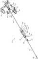
图1是医疗装置的透视图。Figure 1 is a perspective view of a medical device.
图2是图1的医疗装置的分解图。FIG. 2 is an exploded view of the medical device of FIG. 1 .
图3是图1的医疗装置的柄部的细节图,其中柄部的一部分已被移除。3 is a detail view of the handle of the medical device of FIG. 1 with a portion of the handle removed.
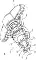
图4A是处于未联接构型的图1的医疗装置的指示器和远侧衬圈的透视图。4A is a perspective view of the indicator and distal collar of the medical device of FIG. 1 in an uncoupled configuration.
图4B是处于联接构型的图4A的指示器和远侧衬圈的透视图。4B is a perspective view of the indicator and distal collar of FIG. 4A in a coupled configuration.
图5A是处于未联接构型的图1的医疗装置的内部构件和外部构件的透视图。5A is a perspective view of inner and outer components of the medical device of FIG. 1 in an uncoupled configuration.
图5A1是图5A的内部构件通过线5A1-5A1的剖视图。5A1 is a cross-sectional view of the internal components of FIG. 5A through line 5A1-5A1.
图5A2是图5A的内部构件通过线5A2-5A2的剖视图。5A2 is a cross-sectional view of the internal components of FIG. 5A through line 5A2-5A2.
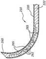
图5B是处于未偏转构型的图1的医疗装置的工作端部部分的剖视图。5B is a cross-sectional view of a working end portion of the medical device of FIG. 1 in an undeflected configuration.
图5C是处于偏转构型的图5B的工作端部部分的剖视图。5C is a cross-sectional view of the working end portion of FIG. 5B in a deflected configuration.
图6A是处于未联接构型的内部构件和外部构件的另一实施方案的透视图。Figure 6A is a perspective view of another embodiment of the inner and outer members in an uncoupled configuration.
图6B是类似于图5B的工作端部部分的工作端部部分的剖视图,包括处于未偏转构型的图6A的内部构件和外部构件。Figure 6B is a cross-sectional view of a working end portion similar to that of Figure 5B, including the inner and outer members of Figure 6A in an undeflected configuration.
图6C是处于偏转构型的图6B的工作端部部分的剖视图。6C is a cross-sectional view of the working end portion of FIG. 6B in a deflected configuration.
图7A是图1的医疗装置的一部分的剖视图。7A is a cross-sectional view of a portion of the medical device of FIG. 1 .
图7B是图1的医疗装置通过线7B-7B的剖视图。7B is a cross-sectional view of the medical device of FIG. 1 through
图8A是致动器部分的远侧端部的透视图。8A is a perspective view of the distal end of the actuator portion.
图8B是凹构件的远侧端部的透视图。Figure 8B is a perspective view of the distal end of the female member.
具体实施方式Detailed ways
本文所公开的各种实施方案通常涉及包括骨凿的医疗装置。在某些实施方案中,医疗装置可包括形成工作端部部分的内部构件和外部构件。内部构件的远侧端部部分可包括凹入部分,并且外部构件的远侧端部部分可包括多个狭槽。凹入部分和多个狭槽可以进行交互以允许工作端部部分的偏转(例如,在单个平面中)。在一些实施方案中,医疗装置可包括指示器,其中指示器被构造成将工作端部部分的偏转方向发送给执业医师或用户。The various embodiments disclosed herein relate generally to medical devices that include osteotomes. In certain embodiments, a medical device may include an inner member and an outer member that form a working end portion. The distal end portion of the inner member may include a recessed portion, and the distal end portion of the outer member may include a plurality of slots. The recessed portion and the plurality of slots may interact to allow deflection of the working end portion (eg, in a single plane). In some embodiments, the medical device may include an indicator, wherein the indicator is configured to communicate the deflection direction of the working end portion to a practitioner or user.
在各种实施方案中,医疗装置可包括扭矩释放机构。当施加到医疗装置的扭矩量超过预先确定的值时,扭矩释放机构可以被构造成可释放地使医疗装置的第一部分与医疗装置的第二部分未联接。扭矩释放机构可以限制或防止医疗装置的一个或多个部件在医疗装置的使用期间受到损害或损坏。In various embodiments, the medical device may include a torque release mechanism. The torque release mechanism may be configured to releasably decouple the first portion of the medical device from the second portion of the medical device when the amount of torque applied to the medical device exceeds a predetermined value. The torque release mechanism may limit or prevent damage or damage to one or more components of the medical device during use of the medical device.
应当理解,为了使本公开简化,有时将多个特征集中在单个实施方案、图或其描述中。许多这些特征可以单独使用和/或彼此组合使用。It will be appreciated that, for the purpose of simplifying the disclosure, various features are sometimes grouped in a single embodiment, figure, or description thereof. Many of these features can be used alone and/or in combination with each other.
参考附图将理解实施方案,其中相同的部分始终由相同的数字表示。应当容易理解,如本文附图总体描述且示出的本公开的部件可被布置和设计成多种不同的构型。因此,以下对设备的实施方案的更详细描述并非旨在限制本公开的范围,而仅仅是本公开的可能实施方案的代表。在一些情况下,未详细示出或描述众所周知的结构、材料或操作。尽管在附图中呈现了实施方案的各种方面,除非明确指示,否则附图不必按比例绘制。The embodiments will be understood with reference to the drawings, wherein like parts are designated by like numerals throughout. It should be readily understood that the components of the present disclosure as generally described and illustrated in the drawings herein may be arranged and designed in many different configurations. Accordingly, the following more detailed description of embodiments of apparatuses is not intended to limit the scope of the present disclosure, but is merely representative of possible embodiments of the present disclosure. In some instances, well-known structures, materials, or operations are not shown or described in detail. Although various aspects of the embodiments are presented in drawings, the drawings are not necessarily drawn to scale unless explicitly indicated.
短语“连接至”、“联接至”和“与…连通”是指两个或更多个实体之间的任何形式的相互作用,包括但不限于机械、电、磁、电磁、流体和热相互作用。两个部件可联接到彼此,即便其不与彼此直接接触。例如,两个部件可通过中间部件联接至彼此。The phrases "connected to," "coupled to," and "in communication with" refer to any form of interaction between two or more entities, including but not limited to mechanical, electrical, magnetic, electromagnetic, fluid, and thermal interactions effect. Two parts can be coupled to each other even though they are not in direct contact with each other. For example, two components may be coupled to each other through an intermediate component.
术语“近侧”和“远侧”是指医疗装置的相反两端,包括本文所公开的装置。如本文所用,医疗装置的近侧部分是在使用期间最接近执业医师的部分,而远侧部分是在相反端的部分。例如,医疗装置的近侧被定义为在医疗装置的使用期间最接近执业医师的端部。远侧端部是沿着医疗装置的纵向方向与近侧端部相对的端部。The terms "proximal" and "distal" refer to opposite ends of a medical device, including the devices disclosed herein. As used herein, the proximal portion of the medical device is the portion closest to the practitioner during use, while the distal portion is the portion at the opposite end. For example, the proximal side of a medical device is defined as the end closest to the medical practitioner during use of the medical device. The distal end is the end opposite the proximal end in the longitudinal direction of the medical device.
术语“弹性”是指具有特定形状的部件、装置或物体,其然后可以弹性变形为不同的形状,但是当无约束时可以恢复到初始形状。例如,弹性臂在无约束(即,当不与凹构件的脊接合时)时可以具有第一形状,并且在使用中,然后可以约束(即,暂时与凹构件的脊接合)弹性臂以使弹性臂弹性变形为第二形状(即,由于与凹构件的脊的一部分相互作用而径向向外移位),然后无约束(即,从与凹构件的脊的部分的接合中移除)使得弹性臂返回其第一形状或基本上返回其第一形状。The term "elastic" refers to a part, device, or object having a specific shape that can then elastically deform into a different shape, but can return to its original shape when unconstrained. For example, the resilient arms may have a first shape when unconstrained (ie, when not engaged with the ridges of the female member), and in use, may then be constrained (ie, temporarily engaged with the ridges of the female member) to allow the resilient arms to The resilient arm is elastically deformed into the second shape (ie, displaced radially outward due to interaction with a portion of the ridge of the female member) and then unconstrained (ie, removed from engagement with the portion of the ridge of the female member) The resilient arm is returned to its first shape or substantially returned to its first shape.
图1是包括骨凿的医疗装置100的透视图。图2是医疗装置100的分解图。在一些实施方案中,医疗装置100被构造成用于进入椎体内部和/或用于在椎骨松质骨中形成通路。在一些实施方案中,通路可以接收骨填充材料(例如,骨水泥)。如图所示,医疗装置100可包括延伸构件105。延伸构件105可被构造成通过椎骨的椎弓根引入。Figure 1 is a perspective view of a
延伸构件105可包括在延伸构件105的远侧端部113处或其邻近的工作端部部分110。在某些实施方案中,延伸构件105的工作端部部分110可以被构造成逐渐致动(例如,由执业医师),使得工作端部部分110的至少一部分弯制、弯曲和/或偏转选定的程度。指示器或尖端指示器150可以向执业医师发送或指示工作端部部分110的偏转方向。延伸构件105的工作端部部分110也可以被构造成旋转。工作端部部分110的偏转和/或旋转可在椎体中形成弯曲路径和/或腔。例如,偏转和/或旋转可以在椎体中线的方向上形成弯曲路径和/或腔。The
在各种实施方案中,可以缩回医疗装置100并且可以将骨填充材料引入通路和/或腔(例如,经由骨水泥注射管道)。在各种其他实施方案中,医疗装置100可以被构造成用作水泥注射器。例如,在形成弯曲路径和/或腔时,可以通过医疗装置100的至少一部分(例如,通过医疗装置100的内腔)注射骨水泥。In various embodiments, the
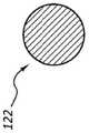
医疗装置100还可包括柄部115,其中柄部115联接到延伸构件105的近侧端部。如下文进一步详细描述的,延伸构件105可包括第一或外部构件120和第二或内部构件122。参考图2,外部构件120具有近侧端部124和远侧端部126。外部构件板125可以联接或构造成联接到外部构件120的近侧端部124。内部构件122还具有近侧端部134和远侧端部136。球形部分137联接或构造成联接到内部构件122的近侧端部134。再次参见图1和图2,延伸构件105可以联接到柄部115,以允许或许可执业医师将延伸构件105驱动到硬组织(例如,骨骼)中,同时或基本同时地,将工作端部部分110致动成偏转或非线性构型(参见,例如图5C)。The
在一些实施方案中,柄部115可由聚合物、金属或任何其他适于承受可用于将医疗装置100驱动到骨骼中的冲击力的材料形成(例如,经由在柄部115上使用锤子或类似装置)。在某些实施方案中,内部构件和外部构件120、122可以由聚合物、金属、金属合金或任何其他合适的材料形成。例如,内部构件和外部构件122、120可以由合适的金属合金形成,诸如不锈钢或镍钛合金(例如,NITINOL)。在各种实施方案中,外部构件120的外径可为约1.5mm至约5.0mm、约2.0mm至约4.0mm、约2.5mm至约3.5mm或另一合适的外径。在各种实施方案中,外部构件120的内径可为约1.0mm至约4.5mm、约1.5mm至约3.5mm、约2.0mm至约3.0mm或另一合适的内径。In some embodiments, handle 115 may be formed from a polymer, metal, or any other material suitable for withstanding the impact forces that may be used to drive
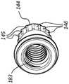
如图所示,柄部115可包括抓持部分140和致动器部分142,其中致动器部分142可相对于抓持部分140旋转。在一些实施方案中,抓持部分140可以被构造成由用户抓握、抓持和/或保持,并且致动器部分142可以被构造成由用户致动和/或旋转(相对于抓持部分140)。抓持部分140可以联接到外部构件120。在一些实施方案中,抓持部分140可以经由外部构件板125和/或远侧衬圈130联接到外部构件120。致动器部分142可以可操作地联接到内部构件122。在各种实施方案中,致动器部分142可以经由球形部分137、凹构件144和/或凸构件147联接到内部构件122。下面将进一步详细讨论抓持部分140、外部构件120、外部构件板125和远侧衬圈130中的每一个的操作。同样,致动器部分142、内部构件122、球形部分137、凹构件144和凸构件147中的每一个的操作也在下文进一步详细讨论。As shown, the
参考图2,医疗装置100还可包括一个或多个O形环118、119。近侧O形环118可以被构造成围绕凹构件144的至少一部分(例如,凹构件144的远侧部分)设置。近侧O形环118可以补偿凹构件144与其他部件之间的公差或配合,以在此类部件之间产生平滑的相互作用。远侧O形环119可被构造成设置在远侧衬圈130的一部分内。例如,远侧O形环119可以设置在远侧衬圈130的锁定构件接收部分131内(下文进一步详细讨论)。远侧O形环119可被构造成在外部构件板125(例如,外部构件板125的远侧表面)与远侧衬圈130之间形成密封。远侧O形环119还可以补偿部件之间的配合或公差的差异,并促进部件的平滑相互作用。在某些实施方案中,医疗装置100还可包括多个垫圈185、186、187。多个垫圈185、186、187可被构造成在远侧衬圈130的近侧的位置处围绕内部构件122设置。在组装医疗装置100时,多个垫圈185、186、187可设置在抓持部分140的至少一部分内。Referring to FIG. 2 , the
图3描绘了医疗装置100的柄部115的一部分,其中抓持部分140的一部分(例如,一半)已被移除。因此,在该视图中可以看到设置或至少部分地设置在柄部115内的医疗装置100的部件的至少一个子集。参考图2和图3,在一些实施方案中,抓持部分140可包括第一部分或一半和第二部分或一半,其中第一部分和第二部分被构造成彼此联接以形成抓持部分140。在一些实施方案中,抓持部分140的第一部分和抓持部分140的第二部分可通过粘合剂、紧固件、卡扣配合和/或环形带116、117中的一种或多种保持在一起。在一些其他实施方案中,抓持部分140可以是单个部件,或者抓持部分140可以包括三个、四个或更多个部分。3 depicts a portion of
远侧衬圈130和抓持部分140可以用作扭矩限制器和/或释放系统。例如,如果将太多的扭矩施加到外部构件120,则远侧衬圈130和抓持部分140可被构造成允许远侧衬圈130相对于抓持部分140旋转。在各种实施方案中,抓持部分140的内表面141的一部分可以接合远侧衬圈130的外表面的一部分,其联接到外部构件120的近侧端部124(例如,经由外部构件板125)。远侧衬圈130可包括主体133和多个弹性构件132,这些弹性构件从远侧衬圈130的主体133的远侧端部向远侧延伸。The
每个弹性构件132的外表面可以是基本上V形的。弹性构件132的外表面可以接合抓持部分140的内表面141的一部分,本文也称为接合表面141。如图所示,接合表面141的轮廓或形状可以基本上镜像弹性构件132的外表面的V形。在锁定构型中,弹性构件132的外表面与接合表面141接合。致动器部分142的旋转使内部构件122移位(即,向近侧或向远侧),并且可以调节工作端部部分110的偏转程度。The outer surface of each
在选定的力下,例如从约0.5英寸-磅到约7.5英寸-磅、从约0.5英寸-磅到约5.0英寸-磅、从约0.5英寸-磅到约2.5英寸-磅的扭矩,或其他合适的扭矩量,远侧衬圈130的旋转可超过预先确定的极限。当向外部构件120提供太大的扭矩(即,处于或高于预先确定的极限的水平)时,弹性构件132可径向向内移位,从而允许远侧衬圈130旋转或转动。远侧衬圈130的此类旋转可以从约0.25英寸-磅到约10英寸-磅的扭矩、约0.5英寸-磅到约7.5英寸-磅的扭矩、约0.5英寸-磅到约5英寸-磅的扭矩或约0.5英寸-磅到约2.5英寸-磅的扭矩或另一合适的扭矩量释放。at a selected force, such as a torque of from about 0.5 in-lb to about 7.5 in-lb, from about 0.5 in-lb to about 5.0 in-lb, from about 0.5 in-lb to about 2.5 in-lb, or For other suitable amounts of torque, rotation of the
再次参见图3,医疗装置100可包括指示器150。如上所述,指示器150可以定位或设置成发送或指示(例如,向执业医师发送或指示)工作端部部分110的取向(例如,指示偏转的方向)。如图所示,指示器150包括内腔151。因此,指示器150可以设置在外部构件120的至少一部分上方和/或周围。指示器150还可包括指示器臂152,其中指示器臂152从指示器150的纵向轴线径向向外延伸。指示器臂152可以设置在工作端部部分110的偏转方向上。如下文进一步详述,工作端部部分110可以被构造成在单个平面内和/或在某个方向上偏转。将指示器150联接到外部构件120,使得外部构件120和指示器150一起旋转,可以因此保持指示器臂152与工作端部部分110的偏转的方向对准,即使在外部构件120和延伸构件105的其他部件由于上述扭矩限制部件的滑动或移位而相对于抓持部分140旋转的情况下也是如此。Referring again to FIG. 3 ,
如图所示,指示器臂152的端部部分可以形成弯制或弯曲。当指示器150联接到医疗装置100时,指示器臂152的端部部分可朝向致动器部分142向近侧弯制或弯曲。如图所示,指示器臂152围绕抓持部分140的外表面的至少一部分设置。换句话说,指示器臂152的内表面(即,指示器臂152的表面最靠近外部构件120的纵向轴线设置)可以基本上与抓持部分140的外表面的至少一部分贴合。As shown, the end portions of the
在一些实施方案中,指示器150可以由聚合物、金属或其他合适的材料形成。例如,指示器150可以由模制的丙烯腈-丁二烯-苯乙烯(ABS)、聚碳酸酯、尼龙等形成。In some embodiments,
图4A是处于未联接或解锁构型的远侧衬圈130和指示器150的透视图。图4B是处于联接或锁定构型的远侧衬圈130和指示器150的透视图。指示器150可包括内腔151,其中内腔151可在指示器150的近侧端部153与远侧端部154之间延伸。指示器臂152可以从指示器150的远侧端部154处或其邻近的位置延伸。此外,指示器150还可包括锁定构件155,其中锁定构件155设置在指示器150的近侧端部153处或其邻近。锁定构件155可被构造成与远侧衬圈130的锁定构件接收部分131互锁和/或配合。4A is a perspective view of
锁定构件155可包括一个或多个延伸部156,其从指示器150的纵向轴线处径向向外延伸。在一些实施方案中,锁定构件155可被构造成将指示器150联接和/或固定到远侧衬圈130,例如,在锁定构件接收部分131处。如图所示,锁定构件接收部分131可以是基本上X形或加号形状。锁定构件接收部分131的第一区段可包括延伸穿过远侧衬圈130的开口。锁定构件接收部分131的第二区段(其与锁定构件接收部分131的第一区段旋转偏移约90°)可以包括两个凹进部分138,这两个凹进部分被构造成接收和/或接合锁定构件155的两个延伸部156。在一些其他实施方案中,锁定构件155和/或锁定构件接收部分131可以是T形、星形或其他合适的形状。例如,锁定构件155可包括一个、三个、四个或更多个延伸部156。同样,锁定构件接收部分131可包括一个、三个、四个或更多个凹进部分。The locking
在一些实施方案中,将指示器150联接到远侧衬圈130可包括通过锁定构件接收部分131中的开口向近侧设置指示器150,使得锁定构件155设置在锁定构件接收部分131的近侧。然后指示器150可以围绕其纵向轴线旋转(例如,如图4A和图4B中所示的约90°),使得延伸部156基本上与锁定构件接收部分131的凹进部分138对准。然后,指示器150可相对于远侧衬圈130向远侧移位,使得延伸部156设置在锁定构件接收部分131的每个凹进部分138内。In some embodiments, coupling the
如上所述,远侧衬圈130联接或被构造成联接外部构件120和指示器150两者。例如,在一些情况下,当外部构件120延伸穿过指示器150的内腔151时,外部构件板125可与远侧衬圈130上的凹槽配合。指示器150可以联接到远侧衬圈130,使得指示器150的指示器臂152基本上与工作端部部分110的偏转的方向对准。此外,在远侧衬圈130旋转时(例如,在释放过量扭矩时),指示器150的指示器臂152可保持与工作端部部分110的偏转方向基本上对准。远侧衬圈130的旋转可导致或实现指示器150和外部构件120中的每一个的旋转。As described above, the
图5A是外部构件120和内部构件122的透视图。图5B是处于未偏转构型(例如,线性构型)的图1的医疗装置100的工作端部部分110的剖视图。图5C描绘了处于偏转构型(例如,非线性构型)的图5B的工作端部部分110。如图5A中的箭头所示,内部构件122可设置在外部构件120的内腔121内。如上所述,外部构件板125可以联接到外部构件120的近侧端部124。另外,球形部分137可以联接到内部构件122的近侧端部134。FIG. 5A is a perspective view of
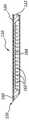
如图所示,外部构件120可包括外部工作端部部分111a,内部构件122可包括内部工作端部部分111b。在一些实施方案中,外部工作端部部分111a和内部工作端部部分111b可配合以形成工作端部部分110。外部工作端部部分111a可包括多个狭槽或凹口162(为清楚起见,在图中仅标记了狭槽162的子集)。内部构件122的内部工作端部部分111b可包括凹入部分164。在一些实施方案中,通过外部工作端部部分111a的多个狭槽162与内部工作端部部分111b的凹入部分164之间的配合,延伸构件105的工作端部部分110可以弯制、弯曲和/或偏转(参见,例如,图5C)。As shown,
工作端部部分110(包括外部工作端部部分和内部工作端部部分111a、111b中的每一个)能够以基本上紧密的半径弯制、弯曲和/或偏转。在偏转构型中,工作端部部分110的远侧端部113可相对于工作端部部分110近侧的延伸构件105的一部分的纵向轴线移位至少约5°、至少约10°、至少约20°、至少约30°、至少约40°、至少约50°、至少约60°、至少约70°、至少约80°、至少约90°、至少约100°或更多度。在一些实施方案中,在偏转构型中,工作端部部分110的远侧端部113可以相对于工作端部部分110的近侧的延伸构件105的一部分的纵向轴线移位,相对于工作端部部分110的近侧的延伸构件105的一部分的纵向轴线移位约50°至约110°、约60°至约100°或约70°至约90°。换句话说,在未偏转构型中,工作端部部分110的远侧端部113可以基本上沿着延伸构件105的纵向轴线设置。然而,在偏转构型中,工作端部部分110的远侧端部113可以远离延伸构件105的纵向轴线移位(即,远离纵向轴线预先确定的度)。The working end portion 110 (including each of the outer and inner working
狭槽162可以是相对于外部构件120的纵向轴线垂直或成角度的任何狭槽。如图5B所示,内部构件122的凹入部分164可以设置在工作端部部分110的相对于外部构件120的多个狭槽162的相对侧或者基本上相对侧。换句话讲,内部构件122的凹入部分164可以基本上与外部构件120的多个狭槽162相对地取向(即,当内部构件122如图所示联接到外部构件120时)。
如本文所述和/或如图所示,在工作端部部分110的弯制、弯曲和/或偏转期间,包括凹入部分164的内部构件122的构型可以抑制或防止内部工作端部部分111b的断裂、卷曲、折叠或其他故障。在一些实施方案中,当内部构件122受到约束时(例如,在工作端部部分110偏转时),工作端部部分110可施加约32磅的力。内部构件122和/或凹入部分164可被构造成施加大于约20磅、大于约26磅、大于约38磅、大于约44磅的力,或者另一合适量值的力。As described herein and/or as shown, the configuration of
在某些实施方案中,外部构件120的远侧端部126可以联接到内部构件122的远侧端部136,例如,在联接部分160处。在某些其他实施方案中,与图示的联接部分160相比,联接部分(类似于联接部分160)可以相对于远侧端部113或工作端部部分110更靠近地设置。在各种实施方案中,外部构件120可以在联接部分160处焊接到内部构件122(例如,外部构件120可以激光焊接到内部构件122)。将外部构件120联接到内部构件122的其他机构也在本公开的范围内,例如胶水、互锁部件等。因此,当内部构件122在近侧方向上移位或平移时(即,通过致动器部分142的旋转),外部构件120可以弯制、弯曲或偏转,如图5C所示。此外,致动器部分142的旋转选定量可以使工作端部部分110弯制、弯曲和/或偏转到选定的程度。In certain embodiments, the
如图所示,凹入部分164可以允许或许可内部构件122的内部工作端部部分111b弯制、弯曲和/或偏转。然而,内部工作端部部分111b的弯制、弯曲和/或偏转的方向可以受到外部构件120的狭槽162的定位或位置的限制或约束。在一些实施方案中,工作端部部分110的曲率可以由狭槽162的间距、形状和/或角度控制或限制。As shown, the recessed
当内部构件122相对于外部构件120的近侧部分在近侧方向上移位时,工作端部部分110可以从线性构型(诸如图5B中所示)转变到弯曲构型,其中外部部分120的狭槽162设置在弯制的凹侧(诸如图5C中所示)。内部构件122相对于外部构件120的近侧部分的远侧移位导致工作端部部分110沿相反方向弯曲,使得狭槽162将设置在弯曲的凸侧上。凹入部分164可以在外部构件120内挠曲,例如,如图5B和图5C所示。如下面还讨论的,因此外部构件120和内部构件122的远侧联接以及狭槽162和凹入部分的相对位置可以约束工作部分的弯制在单个平面内弯制。When the
如图所示,外部构件120的远侧端部126和内部构件122的远侧端部136中的每一个都是倾斜的。倾斜构型可以用于或有助于医疗装置100的至少一部分(例如,工作端部部分110)通过椎体的皮质骨进入。在某些实施方案中,外部构件120的远侧端部126或内部构件122的远侧端部136中的仅一个可以是倾斜的。As shown, the
在一些实施方案中,内部构件122和/或内部工作端部部分111b可以被机械加工以形成凹入部分164。其他合适的方法(例如,模制)也可用于形成凹入部分164。在某些实施方案中,外部构件120可以被激光切割以形成多个狭槽162。其他合适的方法也可用于形成多个狭槽162。In some embodiments,
图5A1是通过图5A的线5A1-5A1的内部构件122的剖视图。图5A2是通过图5A的线5A2-5A2的内部构件122的剖视图。参考图5A1,在凹入部分164的近侧位置处横向于内部构件122的纵向轴线的横截面可以是基本上圆形的。在一些其他实施方案中,内部构件122在该位置处的横截面可以以其他方式成形;例如,横截面可以是正方形、矩形、椭圆形等。参考图5A2,在凹入部分164处横向于内部构件122的纵向轴线的横截面可以是基本上分段的(即,图5A1中所示的圆的一部分)。在一些其他实施方案中,内部构件122在凹入部分164处的横截面可以以其他方式成形;例如,横截面可以是正方形、矩形、椭圆形等的一部分或一区段。5A1 is a cross-sectional view of
参考图1至图5C,骨凿或医疗装置100(例如,用于治疗硬组织的医疗装置)可包括柄部115和可操作地联接到柄部115的延伸构件105。延伸构件105可包括设置在外部构件120的至少一部分内的内部构件122。同样,在一些实施方案中,柄部115的至少一部分的致动或旋转可被构造成弯制、弯曲和/或偏转延伸构件105的工作端部部分110。工作端部部分110可以邻近延伸构件105的远侧端部113设置(参见,例如图1)。Referring to FIGS. 1-5C , an osteotome or medical device 100 (eg, a medical device for treating hard tissue) may include a
医疗装置100还可包括可操作地联接到外部构件120的指示器150。在某些实施方案中,指示器150可以将工作端部部分110的偏转方向发送给用户。指示器150可包括细长主体157和联接到细长主体157的近侧端部的锁定构件155。在各种实施方案中,锁定构件155可被构造成将指示器150可操作地联接到外部构件120。指示器150还可包括联接到细长主体157的远侧端部的指示器臂152。指示器臂152可从细长主体157的纵向轴线径向向外延伸。在一些实施方案中,指示器臂152可以被构造成将工作端部部分110的偏转方向发送给用户。The
柄部115可包括可操作地联接到工作端部部分110的致动器部分142。柄部115还可包括抓持部分140,该抓持部分设置在致动器部分142的远侧并且可操作地联接到该致动器部分。在某些实施方案中,致动器部分142的致动和/或旋转可以被构造成使内部构件122相对于外部构件120纵向移位,使得可以在偏转构型与未偏转构型之间转变工作端部部分110,或反之亦然。The
指示器150的锁定构件155可设置在抓持部分140的至少一部分内。此外,指示器臂152可以设置在抓持部分140之外或外部,使得指示器臂152对于用户可见。指示器臂152可以围绕抓持部分140的外表面的至少一部分延伸。在各种实施方案中,指示器150和/或指示器臂152可以是第一颜色(例如,白色),并且抓持部分140可以是第二颜色(例如,蓝色),使得可以增强指示器150和/或指示器臂152的可见性(即,对于用户)。The locking
医疗装置100还可包括远侧衬圈130,该远侧衬圈设置在柄部115内并联接到该柄部。远侧衬圈130可包括外部构件接收部分或外部构件板接收部分135,其被构造成将外部构件板125和/或外部构件120的近侧端部124联接到远侧衬圈130。远侧衬圈130还可包括锁定构件接收部分131,其被构造成将指示器150的近侧端部153和/或锁定构件155联接到远侧衬圈130。在一些实施方案中,外部构件120和指示器150不能相对于远侧衬圈130旋转(例如,至少部分地由于外部构件120和指示器150中的每一个与远侧衬圈130的联接)。
锁定构件155可以联接到指示器150的近侧端部153。继而,锁定构件155可包括从指示器150的纵向轴线径向向外延伸的至少一个延伸部156。如图所示,锁定构件155可包括两个延伸部156,其中两个延伸部156中的每一个设置在指示器150的细长主体157的相对侧上(参见,例如图4A和图4B)。在某些实施方案中,至少一个延伸部156可以接合或被构造成接合锁定构件接收部分131,使得指示器150基本上不能相对于远侧衬圈130旋转。Locking
在各种实施方案中,医疗装置100可包括柄部115和延伸构件105,该延伸构件联接到柄部115并从该柄部向远侧延伸。如上所述,延伸构件105可包括外部构件120。此外,外部构件120可包括从外部构件120的至少远侧端部126处延伸的内腔121。在一些实施方案中,内腔121可以从外部构件120的远侧端部126处延伸到近侧端部124。另外,多个狭槽或凹口162可以设置在外部构件120的壁中。例如,多个狭槽162可以沿着外部构件120的远侧端部部分的长度的至少一部分设置。In various embodiments, the
延伸构件105还可包括内部构件122。内部构件122可设置在外部构件120的至少一部分内。此外,内部构件122可包括凹入部分164。凹入部分164可以沿着内部构件122的远侧端部部分的长度的至少一部分设置。外部构件和内部构件120、122的远侧端部部分(分别包括多个狭槽162和凹入部分164)可以配合和/或进行交互以形成延伸构件105的工作端部部分110。在某些实施方案中,多个狭槽162可以从凹入部分164径向偏移。例如,多个狭槽162可以设置在工作端部部分110与凹入部分164相对的一侧(或基本上的相对侧)。换句话说,多个狭槽162可以从凹入部分164周向偏移,这意味着沿着工作端部部分110的圆周偏移。另外,多个狭槽162和凹入部分164可以配合和/或进行交互,以允许或许可工作端部部分110偏转(例如,在柄部115致动或旋转时)。设置在与凹入部分相对侧上的多个狭槽162的布置可以被构造成将工作端部部分的偏转限制到单个平面。The
在一些实施方案中,凹入部分164的长度可以基本上等于包括多个狭槽162的内部构件122的部分的长度。换句话说,最远侧狭槽162与最近侧狭槽162之间的距离可以基本上等于凹入部分164的远侧端部168与凹入部分164的近侧端部166之间的距离。在一些其他实施方案中,凹入部分164的长度可以大于包括多个狭槽162的内部构件122的部分的长度。在另一些其他实施方案中,凹入部分164的长度可以小于包括多个狭槽162的内部构件122的部分的长度。In some embodiments, the length of the recessed
同样,在各种实施方案中,多个狭槽162和/或凹入部分164可以基本上限制工作端部部分110向单个平面的偏转。换句话说,工作端部部分110可以被构造成仅在单个平面中弯制、弯曲和/或偏转(即,至少部分地由于多个狭槽162和/或凹入部分164)。Also, in various embodiments, the plurality of
外部构件120的远侧端部126或远侧端部部分可以联接(例如,固定地联接)到内部构件122的远侧端部136或远侧端部部分(例如,经由焊接)。柄部115的致动可以使内部构件122相对于外部构件120纵向移位。此类纵向位移可以使工作端部部分110从未偏转构型转变为偏转构型。在某些实施方案中,外部构件120与内部构件122的固定联接可以抑制或限制外部构件120相对于内部构件122的旋转运动。The
内部构件122可包括线材或由线材形成。在一些实施方案中,凹入部分164远侧的线材厚度可以大于凹入部分164处的线材厚度。同样,凹入部分164近侧的线材厚度可以大于凹入部分164处的线材厚度。此外,凹入部分164可包括远侧端部168、中间部分169和近侧端部166。参考图5A,中间部分169可具有第一厚度。此外,内部构件122设置在凹入部分164的近侧的部分可以具有第二厚度,并且内部构件122设置在凹入部分164的远侧的一部分可以具有第三厚度。在例示的实施方案中,第二厚度和第三厚度中的每一个都大于第一厚度。换句话说,凹入部分164(或者凹入部分164的至少一部分)的厚度小于内部构件122的其余部分的厚度(或者内部构件122的其余部分的至少一部分)。The
另外,内部构件122的厚度可以在凹入部分164的近侧端部166处从第一厚度转变到第二厚度,并且内部构件122的厚度可以在凹入部分164的远侧端部168处从第一厚度转变到第三厚度。在一些实施方案中,中间部分169和/或凹入部分164可以被构造成弯制、弯曲或偏转,而内部构件122靠近和/或远离凹入部分164的部分可以不被构造成弯制、弯曲或偏转。此外,如上所述,中间部分169和/或凹入部分164可以是弹性的。Additionally, the thickness of the
图6A至图6C示出了外部构件220和内部构件222,其在某些方面可以类似于结合图1、图2和图5A至图5C描述的外部构件120和内部构件122。应当理解,所有例示的实施方案可具有类似的特征。因此,类似特征以类似的附图标记指代,其中首位数字增至“2”。例如,在图5A至图5C中将狭槽指定为“162”,在图6A至图6C中将类似的狭槽指定为“262”。因此上述有关类似标识的特征的相关公开内容在下文中可能不再重复。此外,图1、图2和图5A至图5C所示的外部构件120和内部构件122和相关部件的具体特征可能未在附图中通过附图标号示出或标识,或者未在后续的书面描述中具体论述。然而,此类特征可能明确地与在其他实施方案中示出和/或关于此类实施方案描述的特征相同或基本上相同。因此,此类特征的相关描述同样适用于图6A至图6C的外部构件220和内部构件222的特征。关于图1、图2和图5A至图5C中所示的外部构件120和内部构件122和部件描述的特征及其变型的任何合适组合可以与图6A至图6C的外部构件220和内部构件222以及部件一起使用,反之亦然。这种公开形式同样适用于后续图中所示和下文描述的其他实施方案。6A-6C illustrate
图6A是外部构件220和内部构件222的透视图。图6B是处于未偏转构型的医疗装置或骨凿(类似于延伸构件105和医疗装置100)的延伸构件的工作端部部分210的剖视图。图6C描绘了处于偏转构型的图6B的工作端部部分210。如图6A中的箭头所示,内部构件222可设置在外部构件220的内腔221内。外部构件板225可以联接到外部构件220的近侧端部224,并且球形部分237可以联接到内部构件222的近侧端部234。FIG. 6A is a perspective view of
如图所示,外部构件220可包括外部工作端部部分211a,内部构件222可包括内部工作端部部分211b。在一些实施方案中,外部工作端部部分211a和内部工作端部部分211b可配合以形成工作端部部分210。外部工作端部部分211a可包括多个狭槽或凹口262。内部工作端部部分211b可包括加强的凹入部分264。As shown,
与上述参考图5A至图5C讨论的凹入部分164相反,加强的凹入部分264可包括多个加强或支撑构件265。如图所示,凹入部分264包括四个加强构件265。在一些实施方案中,凹入部分264可包括一个、两个、三个、五个、六个或更多个加强构件265。一个或多个加强构件265可以加强和/或支撑凹入部分264。例如,当力施加在凹入部分264上时(例如,在工作端部部分210的弯制、弯曲和/或偏转期间),一个或多个加强构件265倾向于将凹入部分的径向位置保持在外部构件220内。这继而又可以抑制或防止凹入部分264扣紧、卷曲或以其他方式故障。当内部构件222设置在外部构件220内时,一个或多个加强构件265可以在凹入部分264的表面与外部构件220的内表面之间的空间上延伸,如图6B所示。因此,一个或多个加强构件265可以支撑凹入部分264。类似地,一个或多个加强构件265可以支撑外部构件220的一部分,该部分邻近凹入部分264设置。In contrast to the recessed
如图6B所示,内部构件222的加强的凹入部分264可以设置在工作端部部分210的相对于外部构件220的多个狭槽262的相对侧。如本文所述和/或如图所示,在工作端部部分210的弯制、弯曲和/或偏转期间,内部构件222、凹入部分264和加强构件265的构型可以抑制或限制内部工作端部部分211b的断裂、卷曲、折叠或其他故障。As shown in FIG. 6B , the reinforced recessed
外部构件220的远侧端部226可以在联接部分260处联接到内部构件222的远侧端部236。因此,当内部构件222在近侧方向上移位或平移时(即,通过类似于致动器部分142的致动器部分的旋转),外部构件220可以弯制、弯曲或偏转,如图6C所示。此外,致动器部分的旋转选定量可以使工作端部部分210弯制、弯曲和/或偏转到选定的程度。The
如图所示,凹入部分264可以允许或许可内部构件222的内部工作端部部分211b在多个方向上弯制、弯曲和/或偏转。然而,内部工作端部部分211b的弯制、弯曲和/或偏转的方向可以受到外部构件220的狭槽262的定位或位置的限制或约束。在一些实施方案中,工作端部部分210的曲率可以由狭槽262的间距、形状和/或角度控制或限制。如图所示,外部构件220的远侧端部226和内部构件222的远侧端部236中的每一个都是倾斜的。在某些实施方案中,外部构件220的远侧端部226或内部构件222的远侧端部236中的仅一个可以是倾斜的。As shown, the recessed
在某些实施方案中,一个或多个加强构件265可以设置在凹入部分264的至少一部分内。例如,加强构件265可以从凹入部分264的表面270延伸到外部构件220的内表面处或其附近的位置。一个或多个加强构件265可以与内部构件222一体地形成。在一些其他实施方案中,一个或多个加强构件265和内部构件222可以是离散的部件。In certain embodiments, one or
图7A是图1的医疗装置100的一部分的剖视图。图7B是通过图1的线7B-7B的医疗装置100的剖视图。如图所示,医疗装置100可包括柄部115。此外,柄部115可包括致动器部分142和抓持部分140。在一些实施方案中,致动器部分142相对于抓持部分140的旋转可以弯制、弯曲和/或偏转延伸构件105的工作端部部分110。致动器部分142可以联接到凹构件144,其中凹构件144可以至少部分地设置在致动器部分142的内腔171内。例如,致动器部分142可以通过在致动器部分142和凹构件144中的每一个的近侧端部处的卡扣配合接合部149联接到凹构件144。在卡扣配合接合部149的远侧位置处,致动器部分142可包括设置在致动器部分142的内腔171内的一个或多个弹性臂143。如图所示,致动器部分142包括两个弹性臂143,其中弹性臂143在内腔171内彼此相对或基本上相对设置。在一些实施方案中,致动器部分142可包括三个、四个或更多个弹性臂143。弹性臂143在致动器部分142内的布置可以变化。例如,弹性臂143可以围绕内腔171的圆周基本均匀地间隔开。又如,弹性臂143可以不均匀地间隔开或以其他方式设置在致动器部分142内。FIG. 7A is a cross-sectional view of a portion of the
此外,一个或多个齿173可以从一个或多个弹性臂143径向向内延伸。如图所示,一个或多个弹性臂143中的每一个包括两个齿173(例如,圆形齿173)。在一些实施方案中,一个或多个弹性臂143可包括一个、三个、四个或更多个齿173。在一些其他实施方案中,第一弹性臂可包括与第二弹性臂不同数量的齿(例如,第一弹性臂可包括一个齿,第二弹性臂可包括三个齿)。一个或多个齿173的形状可以变化。例如,齿173可以是半圆形、三角形或其他合适的形状。Additionally, one or
凹构件144可包括多个脊145和沟槽146。换句话说,凹构件144的外表面可以是齿轮状的。脊145可以从凹构件144的外表面和/或相对于沟槽146径向向外延伸。如图所示,脊145和沟槽146可以被构造成与致动器部分142的齿173接合或进行交互。脊145和/或沟槽146的至少一部分与齿173的至少一部分的接合可以进一步将致动器部分142联接到凹构件144。在致动器部分142旋转时,该接合可允许或驱动凹构件144的旋转。The
另外,凸构件147可以联接到内部构件122。如图所示,内部构件122的近侧端部134联接到凸构件147。例如,联接到内部构件122的近侧端部134的球形部分137可以设置在凸构件147的一部分内,使得凸构件147联接到内部构件122。此类联接可以允许凸构件147移位(例如,纵向地)内部构件122,而基本上在内部构件122上不旋转或施加扭矩。例如,球形部分137可以被构造成在凸构件147的至少一部分内旋转(例如,在基本上球形的腔内)。凸构件147可包括近侧螺纹部分177和远侧部分179。远侧部分179可包括第一表面180a和第二表面180b。如图所示,远侧部分179可以至少部分地设置在抓持部分140的近侧通道167中,其中第一表面和第二表面180a、180b中的每一个可以基本上是平面的或平坦的。在某些实施方案中,凸构件147的第一表面和第二表面180a、180b与近侧通道167的内表面的至少一部分之间的接合或相互作用可以防止或约束凸构件147相对于抓持部分140旋转。Additionally,
多个螺纹178可以设置在凸构件147的近侧螺纹部分177的至少一部分上。凹构件144还可包括内腔182,并且多个螺纹183可设置在内腔182的表面的至少一部分上。凸构件147的多个螺纹178可被构造成与凹构件144的多个螺纹183接合或进行交互(例如,以螺纹方式接合或进行交互)。A plurality of
在各种实施方案中,在致动器部分142致动或旋转时,凸构件147可相对于凹构件144移位或线性移位(例如,向近侧或向远侧),这至少部分是由于凸构件147与凹构件144中的每一个之间的螺纹接合。此类构型可以允许用户在设置在柄部115内的部件的至少一个子集上施加相当大的力(例如,由于力从致动器部分142转变到凹构件144和可以可操作地联接到凹构件144的其他部件)。In various embodiments, when the
在致动器部分142沿第一方向致动期间,凸构件147可相对于抓持部分140向近侧移位。凸构件147的近侧移位可导致或影响内部构件122相对于外部构件120的近侧移位。此外,当内部构件122在联接部分160处联接到外部构件120时,内部构件122相对于外部构件120的近侧移位可导致工作端部部分110的弯制、弯曲和/或偏转。During actuation of the
在一些实施方案中,例如,如果工作端部部分110的远侧端部113被约束在刚性管道或硬骨内,则可以抑制或防止工作端部部分110的偏转。在工作端部部分110完全偏转或基本上完全偏转时,凸构件147的近侧螺纹部分177的近侧端部可抵接或被构造成抵接凹构件144的内腔182的表面的一部分(例如,凸构件147可能会遇到硬障碍物)。In some embodiments, deflection of the working
例如,如果工作端部部分110的远侧端部113被约束在管道或硬骨内,并且如果还没有实现完全偏转,则凸构件147仍然可以在凹构件144内移位。例如,在凸构件147的近侧螺纹部分177的近侧端部与凹构件144的内腔182的表面之间可能仍存在间隙。因此,凸构件147可具有行进或移位的潜在距离。如果用户继续以这种构型旋转致动器部分142(即,非完全偏转构型),则可能超过弹性臂143的保持力(由于工作部分110在骨内的位置而抵抗弯制),弹性臂143中的一个或多个可以径向向外推动,并且一个或多个齿173可以在一个或多个脊145上移位或滑动。例如,齿173可以从第一沟槽146移位到相邻的沟槽146(例如,第二沟槽146)。此外,齿173可以从第一沟槽146移位到第三沟槽146、第四沟槽146等。For example, if the
无论致动器部分142是顺时针还是逆时针(例如,由用户)旋转,弹性臂143和脊145和/或沟槽146都可以类似地进行交互。在某些实施方案中,弹性臂143的横截面可以比例示的弹性臂143更厚或更薄。在一些实施方案中,弹性臂143可以比例示的弹性臂143更短或更长。对弹性臂143的构型的此类调整或修改可用于选择弹性臂143径向向外延伸的所需力(例如,释放力),并在柄部115的部件的至少一个子集上释放扭矩。在各种实施方案中,释放力可以大于使工作端部部分110偏转所需的力。在某些实施方案中,释放力可小于可导致对凸构件147和/或凹构件144的至少一部分的损坏的力。The
如上所述的凹构件144和致动器部分142的联接可以被构造成防止用户在延伸构件105上施加过量的扭矩,这可能会潜在地损坏医疗装置100的一个或多个部件(例如,内部构件122或凸构件147)。例如,在一些实施方案中,从弹性臂143径向向内突出的多个齿173可被构造成当提供过大的扭矩时向外偏转,从而使致动器部分142与凹构件144上的脊145和/或沟槽146脱离接合。更具体地,在选定的扭矩下—例如,大于约6英寸-磅但小于约16英寸-磅的扭矩—致动器部分142可以从凹构件144上的脊145和/或沟槽146脱离接合。此类脱离接合可以防止用户在医疗装置100上施加过量的力。换句话说,致动器部分142可以用作扭矩限制器和/或释放系统。The coupling of
此外,此类脱离接合可以防止球形部分137通过凸构件147的远侧端部移位、断裂和/或挤压。此类脱离接合还可以防止或约束凸构件147的螺纹178和/或凹构件144的螺纹183故障或被剥离。因此,可以保持医疗装置100的正常运行。Additionally, such disengagement may prevent displacement, fracture and/or crushing of
如上所述,医疗装置100可以被构造用于治疗硬组织。在一些实施方案中,医疗装置100可包括延伸构件105,其中延伸构件105包括设置在外部构件120的至少一部分内的内部构件122。柄部115可以可释放地联接到延伸构件105。在某些实施方案中,柄部115的致动(例如,旋转)可以被构造成使得延伸构件105的工作端部部分110在偏转构型与未偏转构型之间转变。此外,扭矩释放机构可以联接到柄部115和内部构件122中的每一个。在各种实施方案中,扭矩释放机构可以被构造成在扭矩释放构型与扭矩保持构型之间转变医疗装置100(如下文进一步详细描述的)。As described above, the
在各种实施方案中,柄部115可包括致动器部分142,其中致动器部分142可释放地联接到内部构件122。柄部115还可包括抓持部分140,其中抓持部分140设置在致动器部分142的远侧并且可旋转地联接到该致动器部分。此外,抓持部分140可以可释放地联接到外部构件120。在一些实施方案中,医疗装置100可包括一个以上的扭矩释放机构。例如,第一或近侧扭矩释放机构可以联接到致动器部分142和内部构件122中的每一个。近侧扭矩释放机构可被构造成使得在扭矩释放构型(例如,近侧扭矩释放构型)与扭矩保持构型(例如,近侧扭矩保持构型)之间转换内部构件122。另外,第二或远侧扭矩释放机构可以联接到抓持部分140和外部构件120中的每一个。远侧扭矩释放机构可被构造成使得在扭矩释放构型(例如,远侧扭矩释放构型)与扭矩保持构型(例如,远侧扭矩保持构型)之间转换外部构件120。In various embodiments, the
扭矩释放机构还可以被构造成当施加到柄部115的扭矩量超过预先确定的值时,使内部构件122与柄部115未联接。例如,扭矩释放机构可以被构造成限制或防止对医疗装置100的损坏(例如,由于对柄部115和/或医疗装置100施加过量的力)。在一些实施方案中,近侧扭矩释放机构可被构造成当施加到致动器部分142的扭矩量超过第一预先确定的值时,使内部构件122与致动器部分142未联接。此外,远侧扭矩释放机构可以被构造成当施加到外部构件120的扭矩量超过第二预先确定的值时,使外部构件120与抓持部分140未联接。The torque release mechanism may also be configured to decouple the
在一些实施方案中,当医疗装置100和/或扭矩释放机构处于扭矩保持构型时,扭矩可以经由扭矩释放机构或近侧扭矩释放机构在柄部115与延伸构件105之间传递。相比之下,当医疗装置100和/或扭矩释放机构处于扭矩释放构型时,扭矩可能不会经由扭矩释放机构或近侧扭矩释放机构在柄部115与延伸构件105之间传递。In some embodiments, when the
柄部115可包括致动器部分142,其中致动器部分142可至少经由内部构件122可释放地联接到工作端部部分110。在某些实施方案中,致动器部分142的致动可被构造成使内部构件122相对于外部构件120纵向移位。此类移位可使工作端部部分110在偏转构型与未偏转构型之间转变。The
扭矩释放机构的第一部分或近侧扭矩释放机构可以设置在致动器部分142内,并且扭矩释放机构的第二部分或近侧扭矩释放机构可以联接到内部构件122的近侧端部134。此外,扭矩释放机构的第一部分和第二部分或近侧扭矩释放机构可以可释放地彼此联接。A first portion or proximal torque release mechanism may be disposed within the
在各种实施方案中,扭矩释放机构的第一部分或近侧扭矩释放机构可包括从致动器部分142的内表面径向向内延伸的至少一个齿173。扭矩释放机构的第二部分或近侧扭矩释放机构可包括从凹构件144的外表面径向向内延伸的至少一个沟槽146。至少一个沟槽146(即,扭矩释放机构的第二部分或近侧扭矩释放机构)可被构造成接合至少一个齿173(即,扭矩释放机构的第一部分或近侧扭矩释放机构)。In various embodiments, the first portion or proximal torque release mechanism of the torque release mechanism may include at least one
在一些实施方案中,至少一个齿173可以联接到弹性臂143,其中弹性臂143从致动器部分142的内表面的至少一部分径向向内延伸。当医疗装置100和/或扭矩释放机构处于扭矩释放构型时,弹性臂143的远侧部分可相对于致动器部分142的纵向轴线径向向外移位。弹性臂143的至少一部分的此类移位可使至少一个齿173与至少一个沟槽146脱离接合。In some embodiments, at least one
如上所述,医疗装置100还可包括凸构件147。凸构件147可以联接到内部构件122的近侧端部134。另外,凸构件147可以与凹构件144以螺纹方式接合,使得凹构件144的致动(例如,旋转)可以使凸构件147相对于凹构件144纵向移位。As mentioned above, the
致动器部分142的致动可以被构造成接合或导致至少一个齿173与至少一个沟槽146的接合。当医疗装置100处于扭矩保持构型时,此类接合可导致凹构件144的致动。此外,凹构件144的致动可被构造成使内部构件122相对于外部构件120纵向移位。在某些实施方案中,当医疗装置100处于扭矩释放构型时,至少一个齿173可被构造成与至少一个沟槽146脱离接合。在此类构型中(例如,其中至少一个齿173与至少一个沟槽146脱离接合),致动部分142的致动可以不致动或导致凹构件144的致动。如上所述,致动器部分142的致动可包括致动器部分142的至少一部分的旋转。同样,凹构件144的致动可包括凹构件144的至少一部分的旋转。当医疗装置100处于扭矩释放构型时,致动器部分142可以至少与延伸构件105未联接,使得致动器部分142的致动不会使工作端部部分110偏转。Actuation of the
本文还公开了使用医疗装置或骨凿(例如,医疗装置100)的方法。在一些方面,本公开涉及治疗患者或受试者的硬组织(例如,骨骼)的方法。在一些实施方案中,该方法可包括获得医疗装置(诸如医疗装置或骨凿100)。如上所述,医疗装置可包括外部构件和设置在外部构件的一部分内的内部构件。此外,外部构件的远侧端部可以联接到(例如,固定地联接到)内部构件的远侧端部。外部构件和内部构件的远侧端部部分可以形成工作端部部分。Also disclosed herein are methods of using a medical device or osteotome (eg, medical device 100). In some aspects, the present disclosure relates to methods of treating hard tissue (eg, bone) in a patient or subject. In some embodiments, the method may include obtaining a medical device (such as a medical device or osteotome 100). As described above, a medical device may include an outer member and an inner member disposed within a portion of the outer member. Additionally, the distal end of the outer member may be coupled (eg, fixedly coupled) to the distal end of the inner member. The distal end portions of the outer member and inner member may form a working end portion.
在某些实施方案中,治疗硬组织的方法还可包括将医疗装置的工作端部部分推进到患者的硬组织的至少一部分中。工作端部部分可以沿第一方向推进。在各种实施方案中,该方法还可包括致动医疗装置(例如,经由柄部),以使内部构件相对于外部构件纵向移位。因此,沿外部构件的远侧端部部分设置的多个狭槽和沿内部构件的远侧端部部分设置的凹入部分可以进行交互,以使工作端部部分从未偏转构型转变到偏转构型。In certain embodiments, the method of treating hard tissue may further include advancing the working end portion of the medical device into at least a portion of the patient's hard tissue. The working end portion may be advanced in a first direction. In various embodiments, the method may further include actuating the medical device (eg, via the handle) to longitudinally displace the inner member relative to the outer member. Accordingly, the plurality of slots disposed along the distal end portion of the outer member and the recessed portions disposed along the distal end portion of the inner member may interact to transition the working end portion from the undeflected configuration to the deflected configuration structure.
在一些实施方案中,治疗患者的硬组织的方法还可包括观察可操作地联接到外部构件的指示器的布置或方向。此类观察可用于确定工作端部部分的偏转的方向(例如,第一方向)。在观察到指示器的布置时,用户可能希望调节相对于被治疗的硬组织的偏转方向。因此,用户可以调节医疗装置,以使工作端部部分沿第二方向推进(例如,至少部分地基于由指示器发送的偏转方向)。In some embodiments, the method of treating hard tissue of a patient may further include observing the arrangement or orientation of an indicator operably coupled to the external member. Such observations can be used to determine the direction (eg, the first direction) of deflection of the working end portion. Upon viewing the placement of the indicator, the user may wish to adjust the direction of deflection relative to the hard tissue being treated. Accordingly, the user may adjust the medical device to advance the working end portion in the second direction (eg, based at least in part on the deflection direction sent by the indicator).
在某些实施方案中,治疗患者的硬组织的方法可包括获得如本文所述的医疗装置(例如,医疗装置100)。如上所述,医疗装置可包括外部构件和设置在外部构件的至少一部分内的内部构件。外部构件和内部构件中的每一个的远侧端部部分可以配合以形成工作端部部分。此外,柄部可以可释放地联接到工作端部部分。In certain embodiments, a method of treating hard tissue of a patient can include obtaining a medical device (eg, medical device 100 ) as described herein. As described above, the medical device may include an outer member and an inner member disposed within at least a portion of the outer member. The distal end portions of each of the outer member and inner member may cooperate to form a working end portion. Additionally, the handle may be releasably coupled to the working end portion.
治疗患者的硬组织的方法还可包括将工作端部部分推进到患者的硬组织中。执业医师或用户可以致动柄部的至少一部分,以在未偏转构型与偏转构型之间转变工作端部部分。此外,执业医师可以向柄部施加扭矩。在某些实施方案中,施加到柄部的扭矩水平可以超过预先确定的值。因此,柄部的进一步致动可使柄部与工作端部部分未联接(例如,经由扭矩释放机构)。The method of treating hard tissue of a patient may also include advancing the working end portion into the hard tissue of the patient. A practitioner or user may actuate at least a portion of the handle to transition the working end portion between an undeflected configuration and a deflected configuration. Additionally, the practitioner may apply torque to the handle. In certain embodiments, the torque level applied to the handle may exceed a predetermined value. Thus, further actuation of the handle may decouple the handle from the working end portion (eg, via a torque release mechanism).
在各种实施方案中,执业医师可减小施加到柄部的扭矩量,使得柄部重新联接到工作端部部分或重新联接工作端部部分。在各种其他实施方案中,执业医师可以中止或停止向柄部施加扭矩,使得柄部重新联接到工作端部部分或重新联接工作端部部分。另外,执业医师可以调节工作端部部分的位置(例如,在硬组织内)。因此,可以减小施加到医疗装置的扭矩量。然后,执业医师可致动柄部,以在未偏转构型与偏转构型之间进一步转变工作端部部分。In various embodiments, the practitioner may reduce the amount of torque applied to the handle such that the handle is re-coupled to or re-coupled to the working end portion. In various other embodiments, the practitioner may discontinue or stop applying torque to the handle so that the handle is re-coupled to or re-coupled to the working end portion. Additionally, the practitioner can adjust the position of the working end portion (eg, within hard tissue). Therefore, the amount of torque applied to the medical device can be reduced. The practitioner may then actuate the handle to further transition the working end portion between the undeflected configuration and the deflected configuration.
如本领域技术人员可以理解的,受益于本公开,可以从图1至图8B和对应的公开得出附加的方法和/或方法步骤。本文所公开的任何方法包括用于执行所述方法的一个或多个步骤或动作。所述方法步骤和/或动作可彼此互换。换句话讲,除非对于实施方案的正确运行需要特定顺序的步骤或动作,否则可以修改特定步骤和/或动作的顺序和/或用途。As can be appreciated by those skilled in the art, with the benefit of the present disclosure, additional methods and/or method steps may be derived from FIGS. 1-8B and corresponding disclosures. Any method disclosed herein includes one or more steps or actions for performing the method. The method steps and/or actions may be interchanged with each other. In other words, unless a specific order of steps or actions is required for proper functioning of the embodiments, the order and/or use of specific steps and/or actions may be modified.
本说明书通篇提及了近似值,诸如通过使用术语“基本上”来提及。对于每个此类提及而言,应当理解,在一些实施方案中,可能未用近似值指定该值、特征或特性。例如,在使用诸如“约”和“基本上”的修饰词时,这些术语在其范围内包括不带有其修饰词的被修饰词语。例如,在针对特征来叙述术语“基本上圆形的”时,应当理解在另外的实施方案中,该特征可具有精确圆形构型。Approximations are referred to throughout this specification, such as by use of the term "substantially." For each such reference, it should be understood that, in some embodiments, the value, feature, or characteristic may not be specified with an approximation. For example, when modifiers such as "about" and "substantially" are used, these terms include within their scope the modified word without its modifier. For example, when the term "substantially circular" is recited with respect to a feature, it should be understood that in further embodiments, the feature may have a precisely circular configuration.
本说明书通篇对“实施方案”或“所述实施方案”的提及意指,结合该实施方案所述的特定特征、结构或特性包括在至少一个实施方案中。因此,如本说明书通篇所述,引用的短语或其变型不一定全部涉及相同实施方案。Reference throughout this specification to "an embodiment" or "the embodiment" means that a particular feature, structure or characteristic described in connection with the embodiment is included in at least one embodiment. Thus, referenced phrases or variations thereof do not necessarily all refer to the same embodiment as set forth throughout this specification.
类似地,为了使本公开简化,在上述实施方案的描述中,有时将多个特征集中在单个实施方案、图或其描述中。然而,这种公开的方法不应解释为反映以下意图,即任何权利要求需要比该权利要求中明确列举的那些特征更多的特征。相反,如以下权利要求书所反映,本发明的方面在于比任何单个前述公开的实施方案的所有特征更少的特征的组合。Similarly, in the description of the above-described embodiments, various features are sometimes grouped together in a single embodiment, figure, or description thereof for the purpose of simplifying the disclosure. However, this method of disclosure should not be interpreted as reflecting an intention that any claim require more features than those expressly recited in such claim. Rather, as the following claims reflect, inventive aspects lie in less than all features of any single foregoing disclosed embodiment in combination.
该书面公开内容后的权利要求书据此明确地并入到本书面公开内容中,其中每个权利要求独立地作为单独的实施方案。本公开包括独立权利要求与其从属权利要求的所有排列。此外,能够从随后的独立权利要求和从属权利要求中推导出的附加实施方案也明确地并入本书面描述中。The claims following this written disclosure are hereby expressly incorporated into this written disclosure, with each claim standing on its own as a separate embodiment. This disclosure includes all arrangements of independent claims and their dependent claims. Furthermore, additional embodiments which can be derived from the following independent and dependent claims are also expressly incorporated into this written description.
据信,本领域的技术人员可以使用前面的描述来最充分地利用本发明,而无需进一步详细说明。本文所公开的权利要求和实施方案应理解为仅为说明性和示例性的,而不是以任何方式限制本公开的范围。对于本领域的借助于本公开的普通技术人员将显而易见的是,可在不脱离本公开的基本原理的情况下对上述实施方案的细节作出改变。换句话讲,在以上描述中具体公开的实施方案的各种修改和改善都在所附权利要求的范围内。此外,在不脱离本公开的范围的情况下,本领域的技术人员可以改变本文公开的方法的步骤或动作的顺序。换句话讲,除非对于实施方案的正确运行需要特定顺序的步骤或动作,否则可以修改特定步骤或动作的顺序或用途。因此,本发明的范围由以下权利要求及其等同物限定。It is believed that one skilled in the art can, using the preceding description, utilize the present invention to its fullest without further elaboration. The claims and embodiments disclosed herein are to be understood to be illustrative and exemplary only, and not to limit the scope of the present disclosure in any way. It will be apparent to those of ordinary skill in the art having the benefit of this disclosure that changes may be made in the details of the above-described embodiments without departing from the underlying principles of the disclosure. In other words, various modifications and improvements of the embodiments specifically disclosed in the foregoing description are intended to be within the scope of the appended claims. Furthermore, those of ordinary skill in the art may alter the order of steps or actions of the methods disclosed herein without departing from the scope of the present disclosure. In other words, the order or use of specific steps or actions may be modified unless a specific order of steps or actions is required for proper functioning of the embodiments. Accordingly, the scope of the present invention is to be defined by the following claims and their equivalents.
Claims (8)
Applications Claiming Priority (5)
| Application Number | Priority Date | Filing Date | Title |
|---|---|---|---|
| US201662432217P | 2016-12-09 | 2016-12-09 | |
| US201662432182P | 2016-12-09 | 2016-12-09 | |
| US62/432,217 | 2016-12-09 | ||
| US62/432,182 | 2016-12-09 | ||
| PCT/US2017/065328WO2018107036A1 (en) | 2016-12-09 | 2017-12-08 | Medical devices for treating hard tissues and related methods |
Publications (2)
| Publication Number | Publication Date |
|---|---|
| CN110035704A CN110035704A (en) | 2019-07-19 |
| CN110035704Btrue CN110035704B (en) | 2022-09-06 |
Family
ID=62487661
Family Applications (1)
| Application Number | Title | Priority Date | Filing Date |
|---|---|---|---|
| CN201780074191.8AActiveCN110035704B (en) | 2016-12-09 | 2017-12-08 | Medical device for treating hard tissue and related methods |
Country Status (4)
| Country | Link |
|---|---|
| US (3) | US10470781B2 (en) |
| EP (1) | EP3551100B1 (en) |
| CN (1) | CN110035704B (en) |
| WO (1) | WO2018107036A1 (en) |
Families Citing this family (20)
| Publication number | Priority date | Publication date | Assignee | Title |
|---|---|---|---|---|
| US6907884B2 (en) | 2002-09-30 | 2005-06-21 | Depay Acromed, Inc. | Method of straddling an intraosseous nerve |
| US8361067B2 (en) | 2002-09-30 | 2013-01-29 | Relievant Medsystems, Inc. | Methods of therapeutically heating a vertebral body to treat back pain |
| US10028753B2 (en) | 2008-09-26 | 2018-07-24 | Relievant Medsystems, Inc. | Spine treatment kits |
| CA2737374C (en) | 2008-09-26 | 2017-03-28 | Relievant Medsystems, Inc. | Systems and methods for navigating an instrument through bone |
| AU2012362524B2 (en) | 2011-12-30 | 2018-12-13 | Relievant Medsystems, Inc. | Systems and methods for treating back pain |
| US10588691B2 (en) | 2012-09-12 | 2020-03-17 | Relievant Medsystems, Inc. | Radiofrequency ablation of tissue within a vertebral body |
| WO2014071161A1 (en) | 2012-11-05 | 2014-05-08 | Relievant Medsystems, Inc. | System and methods for creating curved paths through bone and modulating nerves within the bone |
| US9724151B2 (en) | 2013-08-08 | 2017-08-08 | Relievant Medsystems, Inc. | Modulating nerves within bone using bone fasteners |
| JP6419099B2 (en)* | 2016-01-20 | 2018-11-07 | 日本ライフライン株式会社 | Cautery needle device, induction cautery treatment system and chemical cautery treatment system |
| EP3338646A1 (en)* | 2016-12-21 | 2018-06-27 | National University of Ireland Galway | A biopsy device |
| USD879293S1 (en)* | 2017-09-07 | 2020-03-24 | G21 S.R.L. | Biomedical device |
| USD878586S1 (en) | 2017-09-07 | 2020-03-17 | G21 S.R.L. | Biomedical device |
| US11294414B2 (en) | 2018-04-05 | 2022-04-05 | Medos International Sàrl | Surgical instruments with rotation stop devices |
| CN109199524B (en)* | 2018-10-17 | 2020-04-24 | 郑州大学第一附属医院 | Rib cutter under thoracoscope |
| AU2020346827A1 (en) | 2019-09-12 | 2022-03-31 | Relievant Medsystems, Inc. | Systems and methods for tissue modulation |
| CN111920489B (en)* | 2020-08-06 | 2022-03-18 | 山东颐诺医疗科技有限公司 | Spirally-telescopic lower shell assembly for minimally invasive surgery |
| US12082876B1 (en) | 2020-09-28 | 2024-09-10 | Relievant Medsystems, Inc. | Introducer drill |
| EP4268150A4 (en) | 2020-12-22 | 2024-12-18 | Relievant Medsystems, Inc. | PREDICTION OF CANDIDATES FOR SPINAL NEUROMODULATION |
| CN115523244A (en)* | 2021-06-25 | 2022-12-27 | 创领心律管理医疗器械(上海)有限公司 | Torque device of medical equipment and medical equipment system |
| US12433668B1 (en) | 2021-11-08 | 2025-10-07 | Relievant Medsystems, Inc. | Impedance stoppage mitigation during radiofrequency tissue ablation procedures |
Citations (3)
| Publication number | Priority date | Publication date | Assignee | Title |
|---|---|---|---|---|
| US6592559B1 (en)* | 1998-12-09 | 2003-07-15 | Cook Incorporated | Hollow, curved, superlastic medical needle |
| CN102958456A (en)* | 2010-04-29 | 2013-03-06 | Dfine有限公司 | System for treating vertebral fractures |
| CN102985015A (en)* | 2010-04-29 | 2013-03-20 | Dfine有限公司 | System for treating vertebral fractures |
Family Cites Families (545)
| Publication number | Priority date | Publication date | Assignee | Title |
|---|---|---|---|---|
| US2688329A (en) | 1953-03-19 | 1954-09-07 | American Cystoscope Makers Inc | Catheter |
| US3140623A (en) | 1961-08-29 | 1964-07-14 | Pendleton Tool Ind Inc | Predetermined torque release wrench |
| US3228400A (en) | 1962-12-03 | 1966-01-11 | Thomas A Armao | Cryogenic capsule probes |
| US3503385A (en) | 1965-09-27 | 1970-03-31 | Cordis Corp | Guidable catheter assembly and manipulator therefor |
| US3625200A (en) | 1969-08-26 | 1971-12-07 | Us Catheter & Instr Corp | Controlled curvable tip member |
| DE1953835B2 (en) | 1969-10-25 | 1972-02-24 | Linde Ag, 6200 Wiesbaden | CRYOSURGICAL DEVICE |
| US3664344A (en) | 1970-09-15 | 1972-05-23 | Brymill Corp | Tyned cryosurgical probe |
| US3692465A (en) | 1971-05-11 | 1972-09-19 | Samcoe Holding Corp | Three roll processing apparatus,and method for utilization thereof |
| US3908637A (en) | 1974-04-22 | 1975-09-30 | Louis W Doroshow | Rigid urethral instrument |
| DE2501683C3 (en) | 1975-01-17 | 1979-11-29 | Ernst Leitz Wetzlar Gmbh, 6300 Wetzlar | Polymer composite material for prosthetic use and process for its manufacture |
| US4033331A (en) | 1975-07-17 | 1977-07-05 | Guss Stephen B | Cardiac catheter and method of using same |
| US4900303A (en) | 1978-03-10 | 1990-02-13 | Lemelson Jerome H | Dispensing catheter and method |
| EP0006414B1 (en) | 1978-06-29 | 1984-10-10 | Osteo Ag | Carbon fiber reinforced bone cement |
| US4276880A (en) | 1978-09-14 | 1981-07-07 | Oscar Malmin | Cannula and process |
| US4294251A (en) | 1978-10-17 | 1981-10-13 | Greenwald A Seth | Method of suction lavage |
| US4236520A (en) | 1978-12-04 | 1980-12-02 | Anderson Mark L | Fluid drain or injection tube for an animal's udder |
| US4276860A (en) | 1979-11-01 | 1981-07-07 | Motorola, Inc. | Apparatus for the generation of monostable pulses having predetermined durations independent of input signal period |
| DE2944710A1 (en) | 1979-11-06 | 1981-05-07 | Christos Dr. Dimakos | DEVICE FOR REMOVING A BONE CEMENT TUBE IN A REIMPLANTATION OF AN ARTIFICIAL THIGH NECK |
| DE2949368A1 (en) | 1979-12-07 | 1981-06-11 | Hilti AG, 9494 Schaan | DEVICE FOR DELIVERING ONE OR MULTI-COMPONENT DIMENSIONS |
| US4411266A (en) | 1980-09-24 | 1983-10-25 | Cosman Eric R | Thermocouple radio frequency lesion electrode |
| US5017627A (en) | 1980-10-09 | 1991-05-21 | National Research Development Corporation | Composite material for use in orthopaedics |
| US4337773A (en) | 1980-10-20 | 1982-07-06 | Raftopoulos Demetrios D | Method of and device for placing a barrier in a cavity provided in a bone shaft |
| US4578061A (en) | 1980-10-28 | 1986-03-25 | Lemelson Jerome H | Injection catheter and method |
| US4719968A (en) | 1981-01-15 | 1988-01-19 | Speros Phillip C | Heat exchanger |
| US4399814A (en) | 1981-04-27 | 1983-08-23 | Massachusetts Institute Of Technology | Method and apparatus for pressure-coated bones |
| US4473077A (en) | 1982-05-28 | 1984-09-25 | United States Surgical Corporation | Surgical stapler apparatus with flexible shaft |
| US4595006A (en) | 1982-08-16 | 1986-06-17 | Burke Dennis W | Apparatus for cemented implantation of prostheses |
| US4456017A (en) | 1982-11-22 | 1984-06-26 | Cordis Corporation | Coil spring guide with deflectable tip |
| DE3325111A1 (en) | 1983-07-12 | 1985-01-24 | Merck Patent Gmbh, 6100 Darmstadt | IMPLANTATION MATERIALS |
| US4722948A (en) | 1984-03-16 | 1988-02-02 | Dynatech Corporation | Bone replacement and repair putty material from unsaturated polyester resin and vinyl pyrrolidone |
| CA1227902A (en) | 1984-04-02 | 1987-10-13 | Raymond G. Tronzo | Fenestrated hip screw and method of augmented internal fixation |
| US4682596A (en) | 1984-05-22 | 1987-07-28 | Cordis Corporation | Electrosurgical catheter and method for vascular applications |
| US4619263A (en) | 1984-05-30 | 1986-10-28 | Advanced Cardiovascular Systems, Inc. | Adjustable rotation limiter device for steerable dilatation catheters |
| US4586923A (en) | 1984-06-25 | 1986-05-06 | Cordis Corporation | Curving tip catheter |
| US5114414A (en) | 1984-09-18 | 1992-05-19 | Medtronic, Inc. | Low profile steerable catheter |
| US4888366A (en) | 1984-10-24 | 1989-12-19 | Collagen Corporation | Inductive collagen-based bone repair preparations |
| US5246457A (en) | 1985-03-28 | 1993-09-21 | Collagen Corporation | Xenogeneic collagen/mineral preparations in bone repair |
| US4668295A (en) | 1985-04-25 | 1987-05-26 | University Of Dayton | Surgical cements |
| US4625722A (en) | 1985-05-03 | 1986-12-02 | Murray William M | Bone cement system and method |
| US4742817A (en) | 1985-05-15 | 1988-05-10 | Olympus Optical Co., Ltd. | Endoscopic apparatus having a bendable insertion section |
| CH667209A5 (en) | 1985-07-02 | 1988-09-30 | Sulzer Ag | MEDICAL DEPOT PROBE. |
| US4641654A (en) | 1985-07-30 | 1987-02-10 | Advanced Cardiovascular Systems, Inc. | Steerable balloon dilatation catheter assembly having dye injection and pressure measurement capabilities |
| US4846814A (en) | 1986-01-16 | 1989-07-11 | Sherwood Medical Company | Non-whip catheter |
| US4795602A (en) | 1986-03-19 | 1989-01-03 | Pretchel David A | Two pin shunt and molding method |
| DE3613213A1 (en) | 1986-04-18 | 1987-10-22 | Merck Patent Gmbh | TRICALCIUMPHOSPHATE FOR IMPLANTATION MATERIALS |
| US4747840A (en) | 1986-09-17 | 1988-05-31 | Ladika Joseph E | Selective pulmonary arteriograph catheter |
| US5085861A (en) | 1987-03-12 | 1992-02-04 | The Beth Israel Hospital Association | Bioerodable implant composition comprising crosslinked biodegradable polyesters |
| US4843112A (en) | 1987-03-12 | 1989-06-27 | The Beth Israel Hospital Association | Bioerodable implant composition |
| US4748969A (en) | 1987-05-07 | 1988-06-07 | Circon Corporation | Multi-lumen core deflecting endoscope |
| US4898156A (en) | 1987-05-18 | 1990-02-06 | Mitek Surgical Products, Inc. | Suture anchor |
| US4784638A (en) | 1987-09-17 | 1988-11-15 | Neurodynamics, Inc. | Angled hole ventricular catheter and method of making same |
| US4865586A (en) | 1987-09-21 | 1989-09-12 | Martha Hedberg | Suction stylet for endotracheal intubation |
| CN88203061U (en) | 1988-02-05 | 1988-11-23 | 黄传诗 | Puncture needle for viscera |
| IT1234978B (en) | 1988-06-01 | 1992-06-09 | Tecres Spa | TWO-STAGE CEMENTITIOUS MIXTURE, PARTICULARLY SUITABLE FOR ORTHOPEDIC USES. |
| US4961731A (en) | 1988-06-09 | 1990-10-09 | Sherwood Medical Company | Angiographic catheter with balanced dye injection openings |
| US7431722B1 (en) | 1995-02-27 | 2008-10-07 | Warsaw Orthopedic, Inc. | Apparatus including a guard member having a passage with a non-circular cross section for providing protected access to the spine |
| US5088991A (en) | 1988-07-14 | 1992-02-18 | Novoste Corporation | Fuseless soft tip angiographic catheter |
| US4998923A (en) | 1988-08-11 | 1991-03-12 | Advanced Cardiovascular Systems, Inc. | Steerable dilatation catheter |
| US5156606A (en) | 1988-10-11 | 1992-10-20 | Zimmer, Inc. | Method and apparatus for removing pre-placed prosthetic joints and preparing for their replacement |
| US5264214A (en) | 1988-11-21 | 1993-11-23 | Collagen Corporation | Composition for bone repair |
| US5296026A (en) | 1988-12-02 | 1994-03-22 | Monroe Eugene A | Phosphate glass cement |
| US4982730A (en) | 1988-12-21 | 1991-01-08 | Lewis Jr Royce C | Ultrasonic wound cleaning method and apparatus |
| US4963151A (en) | 1988-12-28 | 1990-10-16 | Trustees Of The University Of Pennsylvania | Reinforced bone cement, method of production thereof and reinforcing fiber bundles therefor |
| US5372587A (en) | 1989-01-09 | 1994-12-13 | Pilot Cariovascular Systems, Inc. | Steerable medical device |
| US5480382A (en) | 1989-01-09 | 1996-01-02 | Pilot Cardiovascular Systems, Inc. | Steerable medical device |
| US4969888A (en) | 1989-02-09 | 1990-11-13 | Arie Scholten | Surgical protocol for fixation of osteoporotic bone using inflatable device |
| US4969870A (en) | 1989-06-07 | 1990-11-13 | The Regents Of The University Of California | Method and apparatus for intraosseous infusions |
| US5049137A (en) | 1989-09-08 | 1991-09-17 | Thompson Jeffrey E | Prepackaged syringe and catheter apparatus for deep administration of a fluid, and method of making same |
| US4961730A (en) | 1989-09-29 | 1990-10-09 | Poncy George W | Hypodermic syringe with sliding cap |
| JPH0358402U (en) | 1989-10-13 | 1991-06-06 | ||
| US5196201A (en) | 1989-10-20 | 1993-03-23 | Bioapatite Ab | Implant material composition, preparation thereof as well as uses thereof and implant product obtainable therefrom |
| US5295980A (en) | 1989-10-30 | 1994-03-22 | Ersek Robert A | Multi-use cannula system |
| US5059193A (en) | 1989-11-20 | 1991-10-22 | Spine-Tech, Inc. | Expandable spinal implant and surgical method |
| US5116305A (en) | 1990-02-01 | 1992-05-26 | Abiomed, Inc. | Curved intra aortic balloon with non-folding inflated balloon membrane |
| US5152744A (en) | 1990-02-07 | 1992-10-06 | Smith & Nephew Dyonics | Surgical instrument |
| US5197971A (en) | 1990-03-02 | 1993-03-30 | Bonutti Peter M | Arthroscopic retractor and method of using the same |
| US5454365A (en) | 1990-11-05 | 1995-10-03 | Bonutti; Peter M. | Mechanically expandable arthroscopic retractors |
| US5092891A (en) | 1990-03-08 | 1992-03-03 | Kummer Frederick J | Cement plug for the medullary canal of a bone and coacting tool for installing same |
| NL9000833A (en) | 1990-04-09 | 1991-11-01 | Cordis Europ | ANGIOGRAPHY CATHETER. |
| US5266248A (en) | 1990-05-10 | 1993-11-30 | Torao Ohtsuka | Method of producing hydroxylapatite base porous beads filler for an organism |
| US5103804A (en) | 1990-07-03 | 1992-04-14 | Boston Scientific Corporation | Expandable tip hemostatic probes and the like |
| US6080801A (en) | 1990-09-13 | 2000-06-27 | Klaus Draenert | Multi-component material and process for its preparation |
| ZA917281B (en) | 1990-09-26 | 1992-08-26 | Cryomedical Sciences Inc | Cryosurgical instrument and system and method of cryosurgery |
| DE4033343A1 (en) | 1990-10-19 | 1992-04-23 | Draenert Klaus | MATERIAL AS THE STARTING MATERIAL FOR THE PRODUCTION OF BONE CEMENT AND METHOD FOR THE PRODUCTION THEREOF |
| US5147334A (en) | 1991-01-02 | 1992-09-15 | Moss James P | Catheter for cholangiography |
| US5231989A (en) | 1991-02-15 | 1993-08-03 | Raychem Corporation | Steerable cannula |
| AU660444B2 (en) | 1991-02-15 | 1995-06-29 | Ingemar H. Lundquist | Torquable catheter and method |
| US5161715A (en) | 1991-03-25 | 1992-11-10 | Giannuzzi Anthony C | Double-barreled epoxy injection gun |
| US5368598A (en) | 1991-04-19 | 1994-11-29 | Hasson; Harrith M. | Method of manipulating an uterus using a bendable manipulator |
| US5188619A (en) | 1991-04-24 | 1993-02-23 | Gene E. Myers Enterprises, Inc. | Internal thoractic artery catheter |
| US5112303A (en) | 1991-05-02 | 1992-05-12 | Pudenz-Schulte Medical Research Corporation | Tumor access device and method for delivering medication into a body cavity |
| US5356629A (en) | 1991-07-12 | 1994-10-18 | United States Surgical Corporation | Composition for effecting bone repair |
| US5211631A (en) | 1991-07-24 | 1993-05-18 | Sheaff Charles M | Patient warming apparatus |
| US5308342A (en) | 1991-08-07 | 1994-05-03 | Target Therapeutics, Inc. | Variable stiffness catheter |
| US5285795A (en) | 1991-09-12 | 1994-02-15 | Surgical Dynamics, Inc. | Percutaneous discectomy system having a bendable discectomy probe and a steerable cannula |
| US5697909A (en) | 1992-01-07 | 1997-12-16 | Arthrocare Corporation | Methods and apparatus for surgical cutting |
| US5697281A (en) | 1991-10-09 | 1997-12-16 | Arthrocare Corporation | System and method for electrosurgical cutting and ablation |
| US5662680A (en) | 1991-10-18 | 1997-09-02 | Desai; Ashvin H. | Endoscopic surgical instrument |
| US5891095A (en) | 1993-05-10 | 1999-04-06 | Arthrocare Corporation | Electrosurgical treatment of tissue in electrically conductive fluid |
| US5681282A (en) | 1992-01-07 | 1997-10-28 | Arthrocare Corporation | Methods and apparatus for ablation of luminal tissues |
| US5284128A (en) | 1992-01-24 | 1994-02-08 | Applied Medical Resources Corporation | Surgical manipulator |
| US5336699A (en) | 1992-02-20 | 1994-08-09 | Orthopaedic Research Institute | Bone cement having chemically joined reinforcing fillers |
| EP0627899B1 (en) | 1992-02-28 | 2001-11-07 | Cohesion Technologies, Inc. | Injectable ceramic compositions and methods for their preparation and use |
| US5269750A (en) | 1992-06-22 | 1993-12-14 | Stryker Corporation | Tip unit for fluid transfer surgical handpiece |
| US5342299A (en) | 1992-07-06 | 1994-08-30 | Catheter Imaging Systems | Steerable catheter |
| US5334626A (en) | 1992-07-28 | 1994-08-02 | Zimmer, Inc. | Bone cement composition and method of manufacture |
| US5343877A (en) | 1992-09-09 | 1994-09-06 | University Of Iowa Research Foundation | Orthopedic implant and method |
| US5380307A (en) | 1992-09-30 | 1995-01-10 | Target Therapeutics, Inc. | Catheter with atraumatic drug delivery tip |
| US5549542A (en) | 1992-11-17 | 1996-08-27 | Life Medical Technologies, Inc. | Deflectable endoscope |
| FR2697995B1 (en) | 1992-11-19 | 1994-12-30 | Celsa Lg | Removable blood filtration device, with variable rigidity, implantable in the body of a patient and allowing the injection of a treating product. |
| US5389073A (en) | 1992-12-01 | 1995-02-14 | Cardiac Pathways Corporation | Steerable catheter with adjustable bend location |
| US5342356A (en) | 1992-12-02 | 1994-08-30 | Ellman Alan G | Electrical coupling unit for electrosurgery |
| US5282821A (en) | 1993-01-26 | 1994-02-01 | Donahue John R | Adjustable surgical instrument |
| US5620447A (en) | 1993-01-29 | 1997-04-15 | Smith & Nephew Dyonics Inc. | Surgical instrument |
| US5833692A (en) | 1993-01-29 | 1998-11-10 | Smith & Nephew, Inc. | Surgical instrument |
| EP0684787B1 (en) | 1993-02-19 | 2004-05-12 | Boston Scientific Corporation | Surgical extractor |
| US5378234A (en) | 1993-03-15 | 1995-01-03 | Pilot Cardiovascular Systems, Inc. | Coil polymer composite |
| US5628771A (en) | 1993-05-12 | 1997-05-13 | Olympus Optical Co., Ltd. | Electromagnetic-wave thermatological device |
| US5531715A (en) | 1993-05-12 | 1996-07-02 | Target Therapeutics, Inc. | Lubricious catheters |
| JPH0751379A (en) | 1993-06-24 | 1995-02-28 | Cardiovascular Dynamics Inc | Injection catheter, intravascular site treating method, and production of catheter |
| US5571088A (en) | 1993-07-01 | 1996-11-05 | Boston Scientific Corporation | Ablation catheters |
| US5860974A (en) | 1993-07-01 | 1999-01-19 | Boston Scientific Corporation | Heart ablation catheter with expandable electrode and method of coupling energy to an electrode on a catheter shaft |
| US5431639A (en) | 1993-08-12 | 1995-07-11 | Boston Scientific Corporation | Treating wounds caused by medical procedures |
| US5616121A (en) | 1993-08-17 | 1997-04-01 | Mckay; Douglas W. | Method for alleviating pain in a wound |
| US5431168A (en) | 1993-08-23 | 1995-07-11 | Cordis-Webster, Inc. | Steerable open-lumen catheter |
| US5449351A (en) | 1993-09-09 | 1995-09-12 | Zohmann; Walter A. | Atraumatic needle for lumbar puncture |
| US5385563A (en) | 1993-09-14 | 1995-01-31 | The Kendall Company | Urodynamic catheter |
| US5360416A (en) | 1993-09-30 | 1994-11-01 | Sherwood Medical Company | Thin-walled anesthesia needles |
| US6001093A (en) | 1993-10-15 | 1999-12-14 | Ep Technologies, Inc. | Systems and methods for creating long, thin lesions in body tissue |
| WO1995010225A1 (en) | 1993-10-15 | 1995-04-20 | Ep Technologies, Inc. | Multiple electrode element for mapping and ablating |
| US5458597A (en) | 1993-11-08 | 1995-10-17 | Zomed International | Device for treating cancer and non-malignant tumors and methods |
| US5599346A (en) | 1993-11-08 | 1997-02-04 | Zomed International, Inc. | RF treatment system |
| US5449301A (en) | 1993-11-17 | 1995-09-12 | Berg Technology, Inc. | Shunt connector |
| US5514137A (en) | 1993-12-06 | 1996-05-07 | Coutts; Richard D. | Fixation of orthopedic devices |
| US6716216B1 (en) | 1998-08-14 | 2004-04-06 | Kyphon Inc. | Systems and methods for treating vertebral bodies |
| US20060100635A1 (en) | 1994-01-26 | 2006-05-11 | Kyphon, Inc. | Inflatable device for use in surgical protocol relating to fixation of bone |
| US20030032963A1 (en) | 2001-10-24 | 2003-02-13 | Kyphon Inc. | Devices and methods using an expandable body with internal restraint for compressing cancellous bone |
| ATE361028T1 (en) | 1994-01-26 | 2007-05-15 | Kyphon Inc | IMPROVED INFLATABLE DEVICE FOR USE IN SURGICAL METHODS OF FIXATION OF BONE |
| US6248110B1 (en) | 1994-01-26 | 2001-06-19 | Kyphon, Inc. | Systems and methods for treating fractured or diseased bone using expandable bodies |
| US7166121B2 (en) | 1994-01-26 | 2007-01-23 | Kyphon Inc. | Systems and methods using expandable bodies to push apart cortical bone surfaces |
| US7044954B2 (en) | 1994-01-26 | 2006-05-16 | Kyphon Inc. | Method for treating a vertebral body |
| US6241734B1 (en) | 1998-08-14 | 2001-06-05 | Kyphon, Inc. | Systems and methods for placing materials into bone |
| US5571189A (en) | 1994-05-20 | 1996-11-05 | Kuslich; Stephen D. | Expandable fabric implant for stabilizing the spinal motion segment |
| US5514130A (en) | 1994-10-11 | 1996-05-07 | Dorsal Med International | RF apparatus for controlled depth ablation of soft tissue |
| US5554114A (en) | 1994-10-20 | 1996-09-10 | Micro Therapeutics, Inc. | Infusion device with preformed shape |
| US5858003A (en) | 1994-10-20 | 1999-01-12 | Children's Medical Center Corporation | Systems and methods for promoting tissue growth |
| US5779688A (en) | 1994-10-28 | 1998-07-14 | Intella Interventional Systems, Inc. | Low profile balloon-on-a-wire catheter with shapeable and/or deflectable tip and method |
| US5549637A (en) | 1994-11-10 | 1996-08-27 | Crainich; Lawrence | Articulated medical instrument |
| US5489275A (en) | 1994-11-14 | 1996-02-06 | Ep Technologies, Inc. | Identification ring for catheter |
| AU4242996A (en) | 1994-11-23 | 1996-06-17 | Navarre Biomedical, Ltd. | Flexible catheter |
| US5535922A (en) | 1994-11-29 | 1996-07-16 | Tah Industries, Inc. | Caulking gun dispensing module for multi-component cartridge |
| CA2209633C (en) | 1995-01-04 | 2008-04-22 | Advanced Cardiovascular Systems, Inc. | Catheter shaft with an oblong transverse cross section |
| US6291547B1 (en) | 1995-02-08 | 2001-09-18 | Materials Evolution And Development Usa Inc. | Bone cement compositions comprising fused fibrous compounds |
| GB0102529D0 (en) | 2001-01-31 | 2001-03-21 | Thales Optronics Staines Ltd | Improvements relating to thermal imaging cameras |
| US6409722B1 (en) | 1998-07-07 | 2002-06-25 | Medtronic, Inc. | Apparatus and method for creating, maintaining, and controlling a virtual electrode used for the ablation of tissue |
| US6312428B1 (en) | 1995-03-03 | 2001-11-06 | Neothermia Corporation | Methods and apparatus for therapeutic cauterization of predetermined volumes of biological tissue |
| US5947964A (en) | 1995-03-03 | 1999-09-07 | Neothermia Corporation | Methods and apparatus for therapeutic cauterization of predetermined volumes of biological tissue |
| US6106524A (en) | 1995-03-03 | 2000-08-22 | Neothermia Corporation | Methods and apparatus for therapeutic cauterization of predetermined volumes of biological tissue |
| US5571085A (en) | 1995-03-24 | 1996-11-05 | Electro-Catheter Corporation | Steerable open lumen catheter |
| US6602248B1 (en) | 1995-06-07 | 2003-08-05 | Arthro Care Corp. | Methods for repairing damaged intervertebral discs |
| US5741320A (en) | 1995-05-02 | 1998-04-21 | Heart Rhythm Technologies, Inc. | Catheter control system having a pulley |
| US6575969B1 (en) | 1995-05-04 | 2003-06-10 | Sherwood Services Ag | Cool-tip radiofrequency thermosurgery electrode system for tumor ablation |
| US7179255B2 (en) | 1995-06-07 | 2007-02-20 | Arthrocare Corporation | Methods for targeted electrosurgery on contained herniated discs |
| US6280413B1 (en) | 1995-06-07 | 2001-08-28 | Medtronic Ave, Inc. | Thrombolytic filtration and drug delivery catheter with a self-expanding portion |
| US5725568A (en) | 1995-06-27 | 1998-03-10 | Scimed Life Systems, Inc. | Method and device for recanalizing and grafting arteries |
| AU6499596A (en) | 1995-07-18 | 1997-02-18 | Edwards, Garland U. | Flexible shaft |
| US5681289A (en) | 1995-08-14 | 1997-10-28 | Medicinelodge Inc. | Chemical dispensing system |
| US5810804A (en) | 1995-08-15 | 1998-09-22 | Rita Medical Systems | Multiple antenna ablation apparatus and method with cooling element |
| US5637091A (en) | 1995-08-31 | 1997-06-10 | Hakky; Said I. | Collapsible catheter |
| US5620467A (en) | 1995-10-10 | 1997-04-15 | Incontrol, Inc. | Implantable atrial defibrillator having cardioverting output voltage limiting for simulating larger storage capacitors |
| DE69633411T2 (en) | 1995-10-13 | 2005-10-20 | Transvascular, Inc., Menlo Park | METHOD AND DEVICE FOR PREVENTING ARTERIAL ATTRACTIONS AND / OR FOR CARRYING OUT OTHER TRANSVASCULAR INTERVENTIONS |
| US5776193A (en) | 1995-10-16 | 1998-07-07 | Orquest, Inc. | Bone grafting matrix |
| US6095149A (en) | 1996-08-13 | 2000-08-01 | Oratec Interventions, Inc. | Method for treating intervertebral disc degeneration |
| US6283960B1 (en) | 1995-10-24 | 2001-09-04 | Oratec Interventions, Inc. | Apparatus for delivery of energy to a surgical site |
| US5624396A (en) | 1995-10-30 | 1997-04-29 | Micro Therapeutics, Inc. | Longitudinally extendable infusion device |
| US7186234B2 (en) | 1995-11-22 | 2007-03-06 | Arthrocare Corporation | Electrosurgical apparatus and methods for treatment and removal of tissue |
| US5709697A (en) | 1995-11-22 | 1998-01-20 | United States Surgical Corporation | Apparatus and method for removing tissue |
| US20030069522A1 (en) | 1995-12-07 | 2003-04-10 | Jacobsen Stephen J. | Slotted medical device |
| US5833632A (en) | 1995-12-07 | 1998-11-10 | Sarcos, Inc. | Hollow guide wire apparatus catheters |
| US5860952A (en) | 1996-01-11 | 1999-01-19 | C. R. Bard, Inc. | Corporeal access tube assembly and method |
| US5885258A (en) | 1996-02-23 | 1999-03-23 | Memory Medical Systems, Inc. | Medical instrument with slotted memory metal tube |
| US6228052B1 (en) | 1996-02-29 | 2001-05-08 | Medtronic Inc. | Dilator for introducer system having injection port |
| US5695513A (en) | 1996-03-01 | 1997-12-09 | Metagen, Llc | Flexible cutting tool and methods for its use |
| US5735829A (en) | 1996-03-22 | 1998-04-07 | Cherian; George | Intercostal anesthetic infusion catheter |
| US6110155A (en) | 1996-04-30 | 2000-08-29 | Medtronic, Inc. | Anti-inflammatory-agent-loaded catheter and method for preventing tissue fibrosis |
| US5902251A (en) | 1996-05-06 | 1999-05-11 | Vanhooydonk; Neil C. | Transcervical intrauterine applicator for intrauterine hyperthermia |
| CA2205696C (en) | 1996-05-21 | 2007-12-11 | Moriaki Kusakabe | Embryonic stem cells |
| US5700157A (en) | 1996-06-05 | 1997-12-23 | D-Link Corporation | Electric jack with display means |
| US5681317A (en) | 1996-06-12 | 1997-10-28 | Johnson & Johnson Professional, Inc. | Cement delivery system and method |
| US6312454B1 (en) | 1996-06-13 | 2001-11-06 | Nitinol Devices & Components | Stent assembly |
| US6136885A (en) | 1996-06-14 | 2000-10-24 | 3M Innovative Proprerties Company | Glass ionomer cement |
| GB2314274A (en) | 1996-06-20 | 1997-12-24 | Gyrus Medical Ltd | Electrode construction for an electrosurgical instrument |
| US6066176A (en) | 1996-07-11 | 2000-05-23 | Oshida; Yoshiki | Orthopedic implant system |
| US7104986B2 (en) | 1996-07-16 | 2006-09-12 | Arthrocare Corporation | Intervertebral disc replacement method |
| US6726684B1 (en) | 1996-07-16 | 2004-04-27 | Arthrocare Corporation | Methods for electrosurgical spine surgery |
| US5820592A (en) | 1996-07-16 | 1998-10-13 | Hammerslag; Gary R. | Angiographic and/or guide catheter |
| EP0925033B1 (en) | 1996-07-18 | 2004-02-25 | Implant Innovations, Inc. | Power-driven osteotome tools for compaction of bone tissue |
| GB9616267D0 (en) | 1996-08-02 | 1996-09-11 | Ranier Ltd | Balloon catheter |
| US6126682A (en) | 1996-08-13 | 2000-10-03 | Oratec Interventions, Inc. | Method for treating annular fissures in intervertebral discs |
| US6280473B1 (en) | 1996-08-19 | 2001-08-28 | Macropore, Inc. | Resorbable, macro-porous, non-collapsing and flexible membrane barrier for skeletal repair and regeneration |
| US5905000A (en) | 1996-09-03 | 1999-05-18 | Nanomaterials Research Corporation | Nanostructured ion conducting solid electrolytes |
| US5855577A (en) | 1996-09-17 | 1999-01-05 | Eclipse Surgical Technologies, Inc. | Bow shaped catheter |
| US6953594B2 (en) | 1996-10-10 | 2005-10-11 | Etex Corporation | Method of preparing a poorly crystalline calcium phosphate and methods of its use |
| US5891027A (en) | 1996-10-21 | 1999-04-06 | Irvine Biomedical, Inc. | Cardiovascular catheter system with an inflatable soft tip |
| US7052493B2 (en) | 1996-10-22 | 2006-05-30 | Epicor Medical, Inc. | Methods and devices for ablation |
| EP1459691A1 (en) | 1996-10-23 | 2004-09-22 | Oratec Interventions, Inc. | Method and apparatus for treating intervertebral discs |
| US5800408A (en) | 1996-11-08 | 1998-09-01 | Micro Therapeutics, Inc. | Infusion device for distributing infusate along an elongated infusion segment |
| US5902839A (en) | 1996-12-02 | 1999-05-11 | Northwestern University | Bone cement and method of preparation |
| US5914356A (en) | 1996-12-06 | 1999-06-22 | Orthovita, Inc. | Bioactive load bearing bone bonding compositions |
| US6332880B1 (en) | 1996-12-19 | 2001-12-25 | Ep Technologies, Inc. | Loop structures for supporting multiple electrode elements |
| US6030360A (en) | 1996-12-30 | 2000-02-29 | Biggs; Robert C. | Steerable catheter |
| US6146355A (en) | 1996-12-30 | 2000-11-14 | Myelotec, Inc. | Steerable catheter |
| US6013591A (en) | 1997-01-16 | 2000-01-11 | Massachusetts Institute Of Technology | Nanocrystalline apatites and composites, prostheses incorporating them, and method for their production |
| US5931829A (en) | 1997-01-21 | 1999-08-03 | Vasca, Inc. | Methods and systems for establishing vascular access |
| JP3527378B2 (en) | 1997-01-31 | 2004-05-17 | テルモ株式会社 | Contrast catheter |
| JP2002515801A (en) | 1997-02-12 | 2002-05-28 | オーレイテック インターヴェンションズ インコーポレイテッド | Concave tip for arthroscopic surgery |
| EP1905392B1 (en) | 1997-03-07 | 2011-05-18 | Kyphon SÀRL | System for percutaneous bone and spinal stabilization, fixation and repair |
| WO2004110300A2 (en) | 2001-07-25 | 2004-12-23 | Disc Orthopaedic Technologies Inc. | Deformable tools and implants |
| IL128261A0 (en) | 1999-01-27 | 1999-11-30 | Disc O Tech Medical Tech Ltd | Expandable element |
| US6063078A (en) | 1997-03-12 | 2000-05-16 | Medtronic, Inc. | Method and apparatus for tissue ablation |
| US5847046A (en) | 1997-03-12 | 1998-12-08 | United States Surgical Corporation | Biodegradable bone cement |
| US5876373A (en) | 1997-04-04 | 1999-03-02 | Eclipse Surgical Technologies, Inc. | Steerable catheter |
| US6524296B1 (en) | 1997-04-17 | 2003-02-25 | Medtronic, Inc. | Vessel cannula having properties varying along the axial length |
| US6165166A (en) | 1997-04-25 | 2000-12-26 | Schneider (Usa) Inc. | Trilayer, extruded medical tubing and medical devices incorporating such tubing |
| US5810867A (en) | 1997-04-28 | 1998-09-22 | Medtronic, Inc. | Dilatation catheter with varied stiffness |
| US5849028A (en) | 1997-05-16 | 1998-12-15 | Irvine Biomedical, Inc. | Catheter and method for radiofrequency ablation of cardiac tissue |
| US6428894B1 (en) | 1997-06-04 | 2002-08-06 | International Business Machines Corporation | Tunable and removable plasma deposited antireflective coatings |
| US5972015A (en) | 1997-08-15 | 1999-10-26 | Kyphon Inc. | Expandable, asymetric structures for deployment in interior body regions |
| US5851212A (en) | 1997-06-11 | 1998-12-22 | Endius Incorporated | Surgical instrument |
| US20020077595A1 (en) | 1998-06-15 | 2002-06-20 | Ronald R Hundertmark | Endovascular coronary sinus catheter and method of use |
| US6048346A (en) | 1997-08-13 | 2000-04-11 | Kyphon Inc. | Systems and methods for injecting flowable materials into bones |
| US5924976A (en) | 1997-08-21 | 1999-07-20 | Stelzer; Paul | Minimally invasive surgery device |
| US5921956A (en) | 1997-09-24 | 1999-07-13 | Smith & Nephew, Inc. | Surgical instrument |
| US6293941B1 (en) | 1997-10-06 | 2001-09-25 | Somnus Medical Technologies, Inc. | Method and apparatus for impedance measurement in a multi-channel electro-surgical generator |
| US6309420B1 (en) | 1997-10-14 | 2001-10-30 | Parallax Medical, Inc. | Enhanced visibility materials for implantation in hard tissue |
| EP1039864B1 (en) | 1997-11-14 | 2006-12-27 | Boston Scientific Limited | Multi-sheath delivery catheter |
| US6280441B1 (en) | 1997-12-15 | 2001-08-28 | Sherwood Services Ag | Apparatus and method for RF lesioning |
| US5997581A (en) | 1997-12-29 | 1999-12-07 | Johnson & Johnson Professional, Inc. | Hip stem cement spacer |
| US6251092B1 (en) | 1997-12-30 | 2001-06-26 | Medtronic, Inc. | Deflectable guiding catheter |
| US5928239A (en) | 1998-03-16 | 1999-07-27 | University Of Washington | Percutaneous surgical cavitation device and method |
| EP1063931A2 (en) | 1998-03-19 | 2001-01-03 | Oratec Interventions, Inc. | Catheter for delivery of energy to a surgical site |
| US7572263B2 (en) | 1998-04-01 | 2009-08-11 | Arthrocare Corporation | High pressure applicator |
| WO1999049819A1 (en) | 1998-04-01 | 1999-10-07 | Parallax Medical, Inc. | Pressure applicator for hard tissue implant placement |
| US6440138B1 (en) | 1998-04-06 | 2002-08-27 | Kyphon Inc. | Structures and methods for creating cavities in interior body regions |
| JP3360810B2 (en) | 1998-04-14 | 2003-01-07 | ペンタックス株式会社 | Method for producing bone replacement material |
| US6106539A (en) | 1998-04-15 | 2000-08-22 | Neosurg Technologies | Trocar with removable, replaceable tip |
| US6064902A (en) | 1998-04-16 | 2000-05-16 | C.R. Bard, Inc. | Pulmonary vein ablation catheter |
| US6019765A (en) | 1998-05-06 | 2000-02-01 | Johnson & Johnson Professional, Inc. | Morsellized bone allograft applicator device |
| US6059739A (en) | 1998-05-29 | 2000-05-09 | Medtronic, Inc. | Method and apparatus for deflecting a catheter or lead |
| CA2333761C (en) | 1998-06-01 | 2008-05-27 | Kyphon Inc. | Expandable preformed structures for deployment in interior body regions |
| US6719773B1 (en) | 1998-06-01 | 2004-04-13 | Kyphon Inc. | Expandable structures for deployment in interior body regions |
| US6706039B2 (en) | 1998-07-07 | 2004-03-16 | Medtronic, Inc. | Method and apparatus for creating a bi-polar virtual electrode used for the ablation of tissue |
| US6123702A (en) | 1998-09-10 | 2000-09-26 | Scimed Life Systems, Inc. | Systems and methods for controlling power in an electrosurgical probe |
| GB9820369D0 (en) | 1998-09-19 | 1998-11-11 | Giltech Ltd | Material |
| US6544215B1 (en) | 1998-10-02 | 2003-04-08 | Scimed Life Systems, Inc. | Steerable device for introducing diagnostic and therapeutic apparatus into the body |
| CA2360938C (en) | 1999-02-02 | 2008-01-08 | Warren Oliver Haggard | Controlled release composite |
| DE60020526T2 (en) | 1999-02-04 | 2006-05-11 | SDGI Holdings, Inc., Wilmington | OSTEOGENIC PASTE COMPOSITIONS AND THEIR USE |
| US6203507B1 (en) | 1999-03-03 | 2001-03-20 | Cordis Webster, Inc. | Deflectable catheter with ergonomic handle |
| US6395007B1 (en) | 1999-03-16 | 2002-05-28 | American Osteomedix, Inc. | Apparatus and method for fixation of osteoporotic bone |
| US6770079B2 (en) | 1999-03-16 | 2004-08-03 | American Osteomedix, Inc. | Apparatus and method for fixation of osteoporotic bone |
| US6183435B1 (en) | 1999-03-22 | 2001-02-06 | Cordis Webster, Inc. | Multi-directional steerable catheters and control handles |
| AU6168699A (en) | 1999-03-24 | 2000-10-09 | Parallax Medical, Inc. | Non-compliant system for delivery of implant material |
| US6506217B1 (en) | 1999-03-29 | 2003-01-14 | Arnett Facial Reconstruction Courses, Inc. | Moldable post-implantation bone filler and method |
| US6689823B1 (en) | 1999-03-31 | 2004-02-10 | The Brigham And Women's Hospital, Inc. | Nanocomposite surgical materials and method of producing them |
| US20040044350A1 (en) | 1999-04-09 | 2004-03-04 | Evalve, Inc. | Steerable access sheath and methods of use |
| US6270476B1 (en) | 1999-04-23 | 2001-08-07 | Cryocath Technologies, Inc. | Catheter |
| US6352533B1 (en) | 1999-05-03 | 2002-03-05 | Alan G. Ellman | Electrosurgical handpiece for treating tissue |
| US6582446B1 (en) | 1999-05-06 | 2003-06-24 | J. Alexander Marchosky | Method and apparatus for percutaneous osteoplasty |
| US6478793B1 (en) | 1999-06-11 | 2002-11-12 | Sherwood Services Ag | Ablation treatment of bone metastases |
| US6890329B2 (en) | 1999-06-15 | 2005-05-10 | Cryocath Technologies Inc. | Defined deflection structure |
| US6479565B1 (en) | 1999-08-16 | 2002-11-12 | Harold R. Stanley | Bioactive ceramic cement |
| US6783515B1 (en) | 1999-09-30 | 2004-08-31 | Arthrocare Corporation | High pressure delivery system |
| JP4454078B2 (en) | 1999-10-08 | 2010-04-21 | 株式会社町田製作所 | Endoscope bending tube and method of manufacturing the same |
| US7081122B1 (en) | 1999-10-19 | 2006-07-25 | Kyphon Inc. | Hand-held instruments that access interior body regions |
| US6575919B1 (en) | 1999-10-19 | 2003-06-10 | Kyphon Inc. | Hand-held instruments that access interior body regions |
| US7641657B2 (en) | 2003-06-10 | 2010-01-05 | Trans1, Inc. | Method and apparatus for providing posterior or anterior trans-sacral access to spinal vertebrae |
| US6241710B1 (en) | 1999-12-20 | 2001-06-05 | Tricardia Llc | Hypodermic needle with weeping tip and method of use |
| US6599961B1 (en) | 2000-02-01 | 2003-07-29 | University Of Kentucky Research Foundation | Polymethylmethacrylate augmented with carbon nanotubes |
| US6383188B2 (en) | 2000-02-15 | 2002-05-07 | The Spineology Group Llc | Expandable reamer |
| US6740090B1 (en) | 2000-02-16 | 2004-05-25 | Trans1 Inc. | Methods and apparatus for forming shaped axial bores through spinal vertebrae |
| US7014633B2 (en) | 2000-02-16 | 2006-03-21 | Trans1, Inc. | Methods of performing procedures in the spine |
| US6740093B2 (en) | 2000-02-28 | 2004-05-25 | Stephen Hochschuler | Method and apparatus for treating a vertebral body |
| US6332894B1 (en) | 2000-03-07 | 2001-12-25 | Zimmer, Inc. | Polymer filled spinal fusion cage |
| US6447514B1 (en) | 2000-03-07 | 2002-09-10 | Zimmer | Polymer filled hip fracture fixation device |
| US6358251B1 (en) | 2000-03-21 | 2002-03-19 | University Of Washington | Method and apparatus for forming a cavity in soft tissue or bone |
| JP4723156B2 (en) | 2000-03-31 | 2011-07-13 | アンジオ ダイナミクス インコーポレイテッド | Tissue biopsy and treatment equipment |
| AU5326701A (en) | 2000-04-05 | 2001-10-23 | Kyphon Inc | Methods and devices for treating fractured and/or diseased bone |
| US6565588B1 (en) | 2000-04-05 | 2003-05-20 | Pathway Medical Technologies, Inc. | Intralumenal material removal using an expandable cutting device |
| AU5317301A (en) | 2000-04-05 | 2001-10-23 | Stx Medical Inc | Intralumenal material removal systems and methods |
| US6638268B2 (en) | 2000-04-07 | 2003-10-28 | Imran K. Niazi | Catheter to cannulate the coronary sinus |
| CN101543422B (en) | 2000-04-07 | 2012-07-04 | 科丰有限公司 | System for determining the expansion direction of an expandable structure within a bone |
| US7815649B2 (en) | 2000-04-07 | 2010-10-19 | Kyphon SÀRL | Insertion devices and method of use |
| US6869445B1 (en) | 2000-05-04 | 2005-03-22 | Phillips Plastics Corp. | Packable ceramic beads for bone repair |
| US6743239B1 (en) | 2000-05-25 | 2004-06-01 | St. Jude Medical, Inc. | Devices with a bendable tip for medical procedures |
| ATE308933T1 (en) | 2000-06-23 | 2005-11-15 | Cryocath Technologies Inc | DEVICE FOR CRYOTREATMENT |
| AU2001271440A1 (en) | 2000-06-27 | 2002-01-08 | Kyphon Inc. | Systems and methods for injecting flowable materials into bones |
| GB0016516D0 (en) | 2000-07-06 | 2000-08-23 | Owen Mumford Ltd | Improvements relating to needle protection devices |
| FR2811538B1 (en) | 2000-07-12 | 2003-02-07 | Spine Next Sa | INTERVERTEBRAL CUTTING TOOL |
| DE60136815D1 (en) | 2000-07-14 | 2009-01-15 | Kyphon Inc | DEVICES FOR TREATING SPINE BODIES |
| DE60141653D1 (en) | 2000-07-21 | 2010-05-06 | Spineology Group Llc | A STRONG, POROUS NET BAG DEVICE AND ITS USE IN BONE SURGERY |
| WO2002013700A2 (en) | 2000-08-11 | 2002-02-21 | Sdgi Holdings, Inc. | Surgical instrumentation and method for treatment of the spine |
| US7114501B2 (en) | 2000-08-14 | 2006-10-03 | Spine Wave, Inc. | Transverse cavity device and method |
| US6669692B1 (en) | 2000-08-21 | 2003-12-30 | Biosense Webster, Inc. | Ablation catheter with cooled linear electrode |
| US6679886B2 (en) | 2000-09-01 | 2004-01-20 | Synthes (Usa) | Tools and methods for creating cavities in bone |
| KR20030084891A (en) | 2000-10-16 | 2003-11-01 | 유니버시티 오브 싸우스 캐롤라이나 | Biocompatible cement containing reactive calcium phosphate nanoparticles and methods for making and using such cement |
| US20020068929A1 (en) | 2000-10-24 | 2002-06-06 | Roni Zvuloni | Apparatus and method for compressing a gas, and cryosurgery system and method utilizing same |
| WO2002034148A2 (en) | 2000-10-25 | 2002-05-02 | Kyphon Inc. | Systems and methods for reducing fractured bone using a fracture reduction cannula |
| US6916306B1 (en) | 2000-11-10 | 2005-07-12 | Boston Scientific Scimed, Inc. | Steerable loop structures for supporting diagnostic and therapeutic elements in contact with body tissue |
| US6576249B1 (en) | 2000-11-13 | 2003-06-10 | El Gendler | Bone putty and method |
| US20040087936A1 (en) | 2000-11-16 | 2004-05-06 | Barrx, Inc. | System and method for treating abnormal tissue in an organ having a layered tissue structure |
| US6511471B2 (en) | 2000-12-22 | 2003-01-28 | Biocardia, Inc. | Drug delivery catheters that attach to tissue and methods for their use |
| EP1363700A4 (en) | 2001-01-11 | 2005-11-09 | Rita Medical Systems Inc | Bone-treatment instrument and method |
| US7008433B2 (en) | 2001-02-15 | 2006-03-07 | Depuy Acromed, Inc. | Vertebroplasty injection device |
| US6648880B2 (en) | 2001-02-16 | 2003-11-18 | Cryocath Technologies Inc. | Method of using cryotreatment to treat brain tissue |
| US7544196B2 (en) | 2001-02-20 | 2009-06-09 | Orthovita, Inc. | System and kit for delivery of restorative materials |
| US6375659B1 (en) | 2001-02-20 | 2002-04-23 | Vita Licensing, Inc. | Method for delivery of biocompatible material |
| DE10108261B4 (en) | 2001-02-21 | 2006-07-20 | Ivoclar Vivadent Ag | Polymerizable composition with particulate composite based filler |
| US20020115742A1 (en) | 2001-02-22 | 2002-08-22 | Trieu Hai H. | Bioactive nanocomposites and methods for their use |
| CN1162187C (en) | 2001-02-22 | 2004-08-18 | 华东理工大学 | Inorganic bone adhesive and its application in human hard tissue repair |
| US6623448B2 (en) | 2001-03-30 | 2003-09-23 | Advanced Cardiovascular Systems, Inc. | Steerable drug delivery device |
| US6575978B2 (en) | 2001-04-05 | 2003-06-10 | Spineology, Inc. | Circumferential resecting reamer tool |
| US6979312B2 (en) | 2001-04-12 | 2005-12-27 | Biotran Corporation, Inc. | Steerable sheath catheters |
| US6837867B2 (en) | 2001-04-30 | 2005-01-04 | Biosense Webster, Inc. | Steerable catheter with reinforced tip |
| US6610058B2 (en) | 2001-05-02 | 2003-08-26 | Cardiac Pacemakers, Inc. | Dual-profile steerable catheter |
| US7160296B2 (en) | 2001-05-10 | 2007-01-09 | Rita Medical Systems, Inc. | Tissue ablation apparatus and method |
| US6484904B1 (en) | 2001-05-21 | 2002-11-26 | Tah Industries, Inc. | Two-component cartridge system |
| ITVI20010126A1 (en) | 2001-05-30 | 2002-11-30 | Tecres Spa | RADIOPACO BONE CEMENT FOR ORTHOPEDIC USE AND METHOD OF REALIZATION |
| US6746451B2 (en) | 2001-06-01 | 2004-06-08 | Lance M. Middleton | Tissue cavitation device and method |
| US20020188300A1 (en) | 2001-06-06 | 2002-12-12 | Arramon Yves P. | Cannula system for hard tissue implant delivery |
| DE10129842C1 (en) | 2001-06-15 | 2003-04-24 | Bam Bundesanstalt Matforschung | Process for the production of a bioactive bone cement and bone cement kit |
| US6814734B2 (en) | 2001-06-18 | 2004-11-09 | Sdgi Holdings, Inc, | Surgical instrumentation and method for forming a passage in bone having an enlarged cross-sectional portion |
| NL1018438C1 (en) | 2001-07-02 | 2003-01-08 | Baat Medical Engineering B V | Foldable and foldable tools for placement in a spine. |
| US6835193B2 (en) | 2001-07-10 | 2004-12-28 | Myocardial Therapeutics, Inc. | Methods for controlled depth injections into interior body cavities |
| US6679906B2 (en) | 2001-07-13 | 2004-01-20 | Radiant Medical, Inc. | Catheter system with on-board temperature probe |
| US6620162B2 (en) | 2001-07-20 | 2003-09-16 | Spineology, Inc. | Device for inserting fill material particles into body cavities |
| US7077842B1 (en) | 2001-08-03 | 2006-07-18 | Cosman Jr Eric R | Over-the-wire high frequency electrode |
| CA2427536A1 (en) | 2001-08-08 | 2003-04-30 | Kaneka Corporation | Dilatation catheter |
| JP3603278B2 (en) | 2001-09-06 | 2004-12-22 | 理学電機工業株式会社 | X-ray fluorescence analysis system and program used therefor |
| US20030050644A1 (en) | 2001-09-11 | 2003-03-13 | Boucher Ryan P. | Systems and methods for accessing and treating diseased or fractured bone employing a guide wire |
| US6893431B2 (en) | 2001-10-15 | 2005-05-17 | Scimed Life Systems, Inc. | Medical device for delivering patches |
| GB0124742D0 (en) | 2001-10-16 | 2001-12-05 | Biocomposites Ltd | Biodegradable materials |
| US7004945B2 (en) | 2001-11-01 | 2006-02-28 | Spinewave, Inc. | Devices and methods for the restoration of a spinal disc |
| US6913594B2 (en) | 2001-12-31 | 2005-07-05 | Biosense Webster, Inc. | Dual-function catheter handle |
| AU2003205148A1 (en) | 2002-01-16 | 2003-09-02 | Eva Corporation | Catheter hand-piece apparatus and method of using the same |
| US6955716B2 (en) | 2002-03-01 | 2005-10-18 | American Dental Association Foundation | Self-hardening calcium phosphate materials with high resistance to fracture, controlled strength histories and tailored macropore formation rates |
| US8882755B2 (en) | 2002-03-05 | 2014-11-11 | Kimberly-Clark Inc. | Electrosurgical device for treatment of tissue |
| US7294127B2 (en) | 2002-03-05 | 2007-11-13 | Baylis Medical Company Inc. | Electrosurgical tissue treatment method |
| US8518036B2 (en) | 2002-03-05 | 2013-08-27 | Kimberly-Clark Inc. | Electrosurgical tissue treatment method |
| US6896675B2 (en) | 2002-03-05 | 2005-05-24 | Baylis Medical Company Inc. | Intradiscal lesioning device |
| SE0201052D0 (en) | 2002-04-04 | 2002-04-04 | Cerbio Tech Ab | Biocompatible cement compositions and method of manufacturing |
| ATE417635T1 (en) | 2002-05-29 | 2009-01-15 | Heraeus Kulzer Gmbh | BONE CEMENT MIXTURE AND X-RAY CONTRAST AGENTS AND METHOD FOR THE PRODUCTION THEREOF |
| US20030225432A1 (en) | 2002-05-31 | 2003-12-04 | Baptiste Reginald C. | Soft tissue retraction device for an endoscopic instrument |
| WO2003101308A1 (en) | 2002-06-04 | 2003-12-11 | Office Of Technology Licensing Stanford University | Device and method for rapid aspiration and collection of body tissue from within an enclosed body space |
| US7166133B2 (en) | 2002-06-13 | 2007-01-23 | Kensey Nash Corporation | Devices and methods for treating defects in the tissue of a living being |
| US20040023384A1 (en) | 2002-07-31 | 2004-02-05 | Isis Pharmaceuticals Inc. | Antisense modulation of G protein-coupled receptor 12 expression |
| US7029468B2 (en) | 2002-06-25 | 2006-04-18 | Enpath Medical, Inc. | Catheter assembly with side wall exit lumen and method therefor |
| US6730095B2 (en) | 2002-06-26 | 2004-05-04 | Scimed Life Systems, Inc. | Retrograde plunger delivery system |
| KR100465985B1 (en) | 2002-07-30 | 2005-01-15 | 재단법인서울대학교산학협력재단 | Bioactive Biphasic Ceramic Compositions for Artificial Bone and Method for Making the Same |
| US7901407B2 (en) | 2002-08-02 | 2011-03-08 | Boston Scientific Scimed, Inc. | Media delivery device for bone structures |
| US7393350B2 (en) | 2002-08-06 | 2008-07-01 | Erbe Elektromedizin Gmbh | Cryo-surgical apparatus and methods |
| US20040087994A1 (en) | 2002-08-29 | 2004-05-06 | Loubert Suddaby | Mechanical bone tamping device for repair of osteoporotic bone fractures |
| US7138442B2 (en) | 2002-08-30 | 2006-11-21 | Biomet, Inc. | Reduced exothermic bone replacement cement |
| US6907884B2 (en) | 2002-09-30 | 2005-06-21 | Depay Acromed, Inc. | Method of straddling an intraosseous nerve |
| US8808284B2 (en) | 2008-09-26 | 2014-08-19 | Relievant Medsystems, Inc. | Systems for navigating an instrument through bone |
| US8613744B2 (en) | 2002-09-30 | 2013-12-24 | Relievant Medsystems, Inc. | Systems and methods for navigating an instrument through bone |
| US8361067B2 (en) | 2002-09-30 | 2013-01-29 | Relievant Medsystems, Inc. | Methods of therapeutically heating a vertebral body to treat back pain |
| US7066942B2 (en) | 2002-10-03 | 2006-06-27 | Wright Medical Technology, Inc. | Bendable needle for delivering bone graft material and method of use |
| WO2004045672A2 (en) | 2002-11-15 | 2004-06-03 | The Government Of The United States As Represented By The Secretary Of The Department Of Health And Human Services | Variable curve catheter |
| US7582309B2 (en) | 2002-11-15 | 2009-09-01 | Etex Corporation | Cohesive demineralized bone compositions |
| US6979352B2 (en) | 2002-11-21 | 2005-12-27 | Depuy Acromed | Methods of performing embolism-free vertebroplasty and devices therefor |
| US20050251267A1 (en) | 2004-05-04 | 2005-11-10 | John Winterbottom | Cell permeable structural implant |
| US6945956B2 (en) | 2002-12-23 | 2005-09-20 | Medtronic, Inc. | Steerable catheter |
| US20060024348A1 (en) | 2002-12-31 | 2006-02-02 | Doxa Aktiebolag | Chemically bonded biomaterial element with tailored properties |
| SE524494C2 (en) | 2002-12-31 | 2004-08-17 | Doxa Ab | Chemically bonded biomaterial elements with tailored properties |
| US7390298B2 (en) | 2003-01-06 | 2008-06-24 | City Of Hope | Expandable surgical retractor for internal body spaces approached with minimally invasive incisions or through existing orifices |
| US20040158237A1 (en) | 2003-02-11 | 2004-08-12 | Marwan Abboud | Multi-energy ablation station |
| JP2006513760A (en) | 2003-02-13 | 2006-04-27 | ジンテーズ アクチエンゲゼルシャフト クール | Injectable bone replacement compound |
| JP2004242936A (en) | 2003-02-14 | 2004-09-02 | Terumo Corp | Puncture needle |
| US6875219B2 (en) | 2003-02-14 | 2005-04-05 | Yves P. Arramon | Bone access system |
| AU2004212942A1 (en) | 2003-02-14 | 2004-09-02 | Depuy Spine, Inc. | In-situ formed intervertebral fusion device |
| GB0307834D0 (en) | 2003-04-04 | 2003-05-14 | Ta Contrast Ab | Composition |
| US20060206116A1 (en) | 2003-05-07 | 2006-09-14 | Yeung Jeffrey E | Injection device for the invertebral disc |
| US7625364B2 (en) | 2003-05-27 | 2009-12-01 | Cardia, Inc. | Flexible center connection for occlusion device |
| CN102201196B (en) | 2003-06-06 | 2014-03-26 | 株式会社半导体能源研究所 | Semiconductor device |
| US7112205B2 (en) | 2003-06-17 | 2006-09-26 | Boston Scientific Scimed, Inc. | Apparatus and methods for delivering compounds into vertebrae for vertebroplasty |
| US8415407B2 (en) | 2004-03-21 | 2013-04-09 | Depuy Spine, Inc. | Methods, materials, and apparatus for treating bone and other tissue |
| EP1646332B1 (en) | 2003-07-18 | 2015-06-17 | Edwards Lifesciences AG | Remotely activated mitral annuloplasty system |
| US7887557B2 (en) | 2003-08-14 | 2011-02-15 | Boston Scientific Scimed, Inc. | Catheter having a cutting balloon including multiple cavities or multiple channels |
| US6923813B2 (en) | 2003-09-03 | 2005-08-02 | Kyphon Inc. | Devices for creating voids in interior body regions and related methods |
| US7824412B2 (en) | 2003-09-05 | 2010-11-02 | Medical Design Instruments LLC | Cement/biologics inserter and method for bone-fastener fixation augmentation |
| DE20314010U1 (en)* | 2003-09-08 | 2005-01-13 | Witte, Peter | Torque limiting device for surgical tool, comprising shaft with toothed segment engaging with elastic elements at inner surface of housing |
| US7156843B2 (en) | 2003-09-08 | 2007-01-02 | Medtronic, Inc. | Irrigated focal ablation tip |
| US8579908B2 (en) | 2003-09-26 | 2013-11-12 | DePuy Synthes Products, LLC. | Device for delivering viscous material |
| US7909833B2 (en) | 2003-09-29 | 2011-03-22 | Depuy Acromed, Inc. | Vertebroplasty device having a flexible plunger |
| US7094202B2 (en) | 2003-09-29 | 2006-08-22 | Ethicon Endo-Surgery, Inc. | Method of operating an endoscopic device with one hand |
| US7998112B2 (en) | 2003-09-30 | 2011-08-16 | Abbott Cardiovascular Systems Inc. | Deflectable catheter assembly and method of making same |
| US7708733B2 (en) | 2003-10-20 | 2010-05-04 | Arthrocare Corporation | Electrosurgical method and apparatus for removing tissue within a bone body |
| DE50304905D1 (en) | 2003-11-18 | 2006-10-12 | Somatex Medical Technologies Gmbh | INJECTION PUMP |
| US20050113836A1 (en) | 2003-11-25 | 2005-05-26 | Lozier Antony J. | Expandable reamer |
| ES2286713T3 (en) | 2003-12-01 | 2007-12-01 | Broockeville Corporation N.V. | MIXING AND DISPENSING DEVICE OF TWO COMPONENTS. |
| US8221424B2 (en) | 2004-12-20 | 2012-07-17 | Spinascope, Inc. | Surgical instrument for orthopedic surgery |
| US7727232B1 (en) | 2004-02-04 | 2010-06-01 | Salient Surgical Technologies, Inc. | Fluid-assisted medical devices and methods |
| US7351280B2 (en) | 2004-02-10 | 2008-04-01 | New York University | Macroporous, resorbable and injectible calcium phosphate-based cements (MCPC) for bone repair, augmentation, regeneration, and osteoporosis treatment |
| US7488322B2 (en) | 2004-02-11 | 2009-02-10 | Medtronic, Inc. | High speed surgical cutting instrument |
| US7641664B2 (en) | 2004-02-12 | 2010-01-05 | Warsaw Orthopedic, Inc. | Surgical instrumentation and method for treatment of a spinal structure |
| US20060064101A1 (en) | 2004-02-12 | 2006-03-23 | Arthrocare Corporation | Bone access system |
| US20050187556A1 (en) | 2004-02-25 | 2005-08-25 | Synecor, Llc | Universal percutaneous spinal access system |
| US7407893B2 (en) | 2004-03-05 | 2008-08-05 | Applied Materials, Inc. | Liquid precursors for the CVD deposition of amorphous carbon films |
| US7959634B2 (en) | 2004-03-29 | 2011-06-14 | Soteira Inc. | Orthopedic surgery access devices |
| US7507241B2 (en) | 2004-04-05 | 2009-03-24 | Expanding Orthopedics Inc. | Expandable bone device |
| US7465318B2 (en) | 2004-04-15 | 2008-12-16 | Soteira, Inc. | Cement-directing orthopedic implants |
| US7452351B2 (en) | 2004-04-16 | 2008-11-18 | Kyphon Sarl | Spinal diagnostic methods and apparatus |
| US9554691B2 (en) | 2004-04-21 | 2017-01-31 | Acclarent, Inc. | Endoscopic methods and devices for transnasal procedures |
| US8163030B2 (en) | 2004-05-06 | 2012-04-24 | Degradable Solutions Ag | Biocompatible bone implant compositions and methods for repairing a bone defect |
| US7722612B2 (en) | 2004-05-19 | 2010-05-25 | Sintea Biotech S.P.A. | Devices, kit and method for kyphoplasty |
| WO2005122938A1 (en) | 2004-06-10 | 2005-12-29 | Arthrocare Corporation | Electrosurgical method and apparatus for removing tissue within a bone body |
| JP2008503275A (en) | 2004-06-16 | 2008-02-07 | ウォーソー・オーソペディック・インコーポレーテッド | Surgical instruments and methods for treatment of spinal structures |
| US20050283148A1 (en) | 2004-06-17 | 2005-12-22 | Janssen William M | Ablation apparatus and system to limit nerve conduction |
| CN101065080B (en) | 2004-07-30 | 2021-10-29 | 德普伊新特斯产品有限责任公司 | Materials and Instruments for Manipulating Bone and Other Tissues |
| US20060085009A1 (en) | 2004-08-09 | 2006-04-20 | Csaba Truckai | Implants and methods for treating bone |
| US7503920B2 (en) | 2004-08-11 | 2009-03-17 | Tzony Siegal | Spinal surgery system and method |
| US20080319445A9 (en) | 2004-08-17 | 2008-12-25 | Scimed Life Systems, Inc. | Apparatus and methods for delivering compounds into vertebrae for vertebroplasty |
| US20060106459A1 (en) | 2004-08-30 | 2006-05-18 | Csaba Truckai | Bone treatment systems and methods |
| US7396360B2 (en) | 2004-09-29 | 2008-07-08 | The Cleveland Clinic Foundation | Minimally invasive method and apparatus for fusing adjacent vertebrae |
| US20080015664A1 (en) | 2004-10-06 | 2008-01-17 | Podhajsky Ronald J | Systems and methods for thermally profiling radiofrequency electrodes |
| US7559932B2 (en) | 2004-12-06 | 2009-07-14 | Dfine, Inc. | Bone treatment systems and methods |
| US7682378B2 (en) | 2004-11-10 | 2010-03-23 | Dfine, Inc. | Bone treatment systems and methods for introducing an abrading structure to abrade bone |
| US20060100706A1 (en) | 2004-11-10 | 2006-05-11 | Shadduck John H | Stent systems and methods for spine treatment |
| US8663225B2 (en) | 2004-11-12 | 2014-03-04 | Medtronic, Inc. | Hydrogel bone void filler |
| US8562607B2 (en) | 2004-11-19 | 2013-10-22 | Dfine, Inc. | Bone treatment systems and methods |
| US8583260B2 (en) | 2004-12-28 | 2013-11-12 | St. Jude Medical, Atrial Fibrillation Division, Inc. | Long travel steerable catheter actuator |
| DE102005025946A1 (en) | 2005-01-26 | 2006-08-03 | Erbe Elektromedizin Gmbh | High frequency surgical device for treating monopolar coagulation of biological tissue, has control unit controlling generator to supply voltage to target region and producing switching off signal if target input reaches final value |
| GB0502384D0 (en) | 2005-02-04 | 2005-03-16 | Instrumedical Ltd | Electro-surgical needle apparatus |
| US20060184192A1 (en) | 2005-02-11 | 2006-08-17 | Markworth Aaron D | Systems and methods for providing cavities in interior body regions |
| US7959601B2 (en) | 2005-02-14 | 2011-06-14 | Biosense Webster, Inc. | Steerable catheter with in-plane deflection |
| US20060200121A1 (en) | 2005-03-03 | 2006-09-07 | Mowery Thomas M | Navigable, multi-positional and variable tissue ablation apparatus and methods |
| JP2006263184A (en) | 2005-03-24 | 2006-10-05 | Gc Corp | Bone cement injection and filling method and leakage prevention bag for injecting and filling bone cement |
| US7497853B2 (en) | 2005-05-05 | 2009-03-03 | Enpath Medical Inc. | Deflectable catheter steering and locking system |
| US20070016130A1 (en) | 2005-05-06 | 2007-01-18 | Leeflang Stephen A | Complex Shaped Steerable Catheters and Methods for Making and Using Them |
| US7442190B2 (en) | 2005-05-13 | 2008-10-28 | Cryocath Technologies Inc. | Contact assessment of balloon catheters |
| US8187327B2 (en) | 2005-05-18 | 2012-05-29 | Kyphon Sarl | Selectively-expandable bone scaffold |
| US20060276797A1 (en) | 2005-05-24 | 2006-12-07 | Gary Botimer | Expandable reaming device |
| WO2006127904A1 (en) | 2005-05-24 | 2006-11-30 | Gary Botimer | Expandable surgical reaming tool |
| US20070016273A1 (en) | 2005-05-26 | 2007-01-18 | Smith & Nephew, Inc. | Electrothermal intervertebral disc treatment |
| US20060293687A1 (en) | 2005-06-07 | 2006-12-28 | Bogert Roy B | Syringe plunger seal |
| US20070010845A1 (en) | 2005-07-08 | 2007-01-11 | Gorman Gong | Directionally controlled expandable device and methods for use |
| US8021365B2 (en) | 2005-07-11 | 2011-09-20 | Kyphon Sarl | Surgical device having interchangeable components and methods of use |
| US20070006692A1 (en)* | 2005-07-11 | 2007-01-11 | Phan Christopher U | Torque limiting device |
| WO2007008667A2 (en) | 2005-07-11 | 2007-01-18 | Kyphon, Inc. | Systems and methods for providing cavities in interior body regions |
| US7794458B2 (en) | 2005-07-22 | 2010-09-14 | Boston Scientific Scimed, Inc. | Bipolar radio frequency ablation device with retractable insulator |
| AU2006279558B2 (en) | 2005-08-16 | 2012-05-17 | Izi Medical Products, Llc | Spinal tissue distraction devices |
| CN2841051Y (en) | 2005-08-24 | 2006-11-29 | 汤枧根 | The umbrella shape therapeutic electrode |
| US20070067034A1 (en) | 2005-08-31 | 2007-03-22 | Chirico Paul E | Implantable devices and methods for treating micro-architecture deterioration of bone tissue |
| US8066712B2 (en) | 2005-09-01 | 2011-11-29 | Dfine, Inc. | Systems for delivering bone fill material |
| US7754246B2 (en) | 2005-09-09 | 2010-07-13 | Wright Medical Technology, Inc. | Composite bone graft substitute cement and articles produced therefrom |
| US20070093840A1 (en) | 2005-10-06 | 2007-04-26 | Pacelli Nicolas J | Flexible shaft |
| KR100778142B1 (en) | 2005-11-09 | 2007-11-29 | 황창모 | Radio frequency ablation electrode for selected tissue removal |
| US7823753B2 (en) | 2005-11-18 | 2010-11-02 | Kovac Karen S | Double barrel caulking gun caddy |
| US7713273B2 (en) | 2005-11-18 | 2010-05-11 | Carefusion 2200, Inc. | Device, system and method for delivering a curable material into bone |
| US7799035B2 (en) | 2005-11-18 | 2010-09-21 | Carefusion 2200, Inc. | Device, system and method for delivering a curable material into bone |
| WO2007078692A2 (en) | 2005-12-23 | 2007-07-12 | The Board Of Trustees Of The Leland Stanford Junior University | Systems and methods for fixation of bone with an expandable device |
| US7993334B2 (en) | 2005-12-29 | 2011-08-09 | Boston Scientific Scimed, Inc. | Low-profile, expanding single needle ablation probe |
| WO2007087400A2 (en) | 2006-01-23 | 2007-08-02 | Osseon Therapeutics, Inc. | Bone cement composite containing particles in a non-uniform spatial distribution and devices for implementation |
| EP1983917B1 (en) | 2006-01-27 | 2014-06-25 | Spinal Ventures, LLC | Low pressure delivery system for delivering a solid and liquid mixture into a target site for medical treatment |
| US20070203500A1 (en) | 2006-02-28 | 2007-08-30 | Vermillion Technologies, Llc | Apparatus and method of shaping an intervertebral space |
| US7976542B1 (en) | 2006-03-02 | 2011-07-12 | Cosman Eric R | Adjustable high frequency electrode |
| US20070270876A1 (en) | 2006-04-07 | 2007-11-22 | Yi-Chen Kuo | Vertebra bone cement introduction system |
| US7905884B2 (en) | 2006-04-27 | 2011-03-15 | Warsaw Orthopedic, Inc. | Method for use of dilating stylet and cannula |
| US7615044B2 (en) | 2006-05-03 | 2009-11-10 | Greatbatch Ltd. | Deflectable sheath handle assembly and method therefor |
| US8075556B2 (en) | 2006-05-23 | 2011-12-13 | Andres Betts | High frequency epidural neuromodulation catheter for effectuating RF treatment in spinal canal and method of using same |
| US20080033422A1 (en) | 2006-08-04 | 2008-02-07 | Turner Paul F | Microwave applicator with margin temperature sensing element |
| US20080058840A1 (en) | 2006-09-01 | 2008-03-06 | Albrecht Thomas E | Implantable coil for insertion into a hollow body organ |
| US20080086142A1 (en) | 2006-10-06 | 2008-04-10 | Kohm Andrew C | Products and Methods for Delivery of Material to Bone and Other Internal Body Parts |
| AU2007231733B2 (en) | 2006-11-28 | 2014-03-13 | Cathrx Ltd | A catheter steering system |
| WO2008076330A1 (en) | 2006-12-15 | 2008-06-26 | Soteira, Inc. | Drills and methods for vertebrostenting |
| EP2099390A2 (en) | 2007-01-09 | 2009-09-16 | Nonlinear Technologies Ltd. | Devices for forming curved or closed-loop structures |
| US20080183265A1 (en) | 2007-01-30 | 2008-07-31 | Cardiac Pacemakers, Inc. | Transvascular lead with proximal force relief |
| US8211099B2 (en) | 2007-01-31 | 2012-07-03 | Tyco Healthcare Group Lp | Thermal feedback systems and methods of using the same |
| US8114084B2 (en) | 2007-03-07 | 2012-02-14 | Vertech, Inc. | Expandable blade device for stabilizing compression fractures |
| WO2008124533A1 (en) | 2007-04-03 | 2008-10-16 | Dfine, Inc. | Bone treatment systems and methods |
| US20080269766A1 (en) | 2007-04-30 | 2008-10-30 | Warsaw Orthopedic, Inc. | Intravertebral reduction device with retention balls |
| ES2627667T3 (en) | 2007-05-18 | 2017-07-31 | Boston Scientific Limited | Hollow joint device that can be twisted |
| US20090131952A1 (en) | 2007-05-21 | 2009-05-21 | Brian Schumacher | Delivery system and method for inflatable devices |
| WO2009048824A1 (en) | 2007-10-09 | 2009-04-16 | Boston Scientific Scimed, Inc. | Electrophysiology electrodes and apparatus including the same |
| US20090105775A1 (en) | 2007-10-19 | 2009-04-23 | David Mitchell | Cannula with lateral access and directional exit port |
| US9510885B2 (en) | 2007-11-16 | 2016-12-06 | Osseon Llc | Steerable and curvable cavity creation system |
| US20090131950A1 (en) | 2007-11-16 | 2009-05-21 | Liu Y King | Vertebroplasty method with enhanced control |
| US20090131867A1 (en) | 2007-11-16 | 2009-05-21 | Liu Y King | Steerable vertebroplasty system with cavity creation element |
| US20090131886A1 (en) | 2007-11-16 | 2009-05-21 | Liu Y King | Steerable vertebroplasty system |
| US20090299282A1 (en) | 2007-11-16 | 2009-12-03 | Osseon Therapeutics, Inc. | Steerable vertebroplasty system with a plurality of cavity creation elements |
| WO2011066465A1 (en) | 2009-11-25 | 2011-06-03 | Osseon Therapeutics, Inc. | Steerable and curvable vertebroplasty system with clog-resistant exit ports |
| WO2009067486A2 (en) | 2007-11-19 | 2009-05-28 | David Lee | Method and apparatus for spinal facet joint fusion using irregularly shaped cortical bone implants |
| WO2009073209A1 (en) | 2007-12-06 | 2009-06-11 | Osseon Therapeutics, Inc. | Vertebroplasty implant with enhanced interfacial shear strength |
| US8353902B2 (en) | 2008-01-31 | 2013-01-15 | Vivant Medical, Inc. | Articulating ablation device and method |
| US20090198243A1 (en) | 2008-02-06 | 2009-08-06 | Melsheimer Jeffry S | Device and method for stabilizing a damaged bone with a bone cement mixture |
| US8262672B2 (en) | 2008-04-16 | 2012-09-11 | Medtronic, Inc. | Medical delivery device construction |
| US8696695B2 (en) | 2009-04-28 | 2014-04-15 | Avinger, Inc. | Guidewire positioning catheter |
| US7762164B2 (en)* | 2008-06-02 | 2010-07-27 | Eca Medical Instruments | Torque-limiting device |
| WO2009155319A1 (en)* | 2008-06-17 | 2009-12-23 | Soteira, Inc. | Devices and methods for fracture reduction |
| EP2307075B1 (en) | 2008-07-15 | 2015-11-11 | Thomas Steffen | Bone cement injection device |
| US20100076476A1 (en) | 2008-07-25 | 2010-03-25 | To John T | Systems and methods for cable-based tissue removal |
| US8246627B2 (en) | 2008-08-07 | 2012-08-21 | Stryker Corporation | Cement delivery device for introducing cement into tissue, the device having a cavity creator |
| US9101734B2 (en) | 2008-09-09 | 2015-08-11 | Biosense Webster, Inc. | Force-sensing catheter with bonded center strut |
| JP5575777B2 (en) | 2008-09-30 | 2014-08-20 | ディファイン, インコーポレイテッド | System used to treat vertebral fractures |
| US8758349B2 (en) | 2008-10-13 | 2014-06-24 | Dfine, Inc. | Systems for treating a vertebral body |
| US20100114184A1 (en) | 2008-10-07 | 2010-05-06 | Brainsgate Ltd. | Flexible tools for preparing bony canals |
| US8355799B2 (en) | 2008-12-12 | 2013-01-15 | Arthrocare Corporation | Systems and methods for limiting joint temperature |
| AU2010205892A1 (en) | 2009-01-15 | 2011-07-21 | Cathrx Ltd | Steerable stylet |
| US20100298832A1 (en) | 2009-05-20 | 2010-11-25 | Osseon Therapeutics, Inc. | Steerable curvable vertebroplasty drill |
| WO2010135602A1 (en) | 2009-05-20 | 2010-11-25 | Osseon Therapeutics, Inc. | Steerable curvable ablation catheter for vertebroplasty |
| US8057403B2 (en) | 2009-05-29 | 2011-11-15 | Promex Technologies, Inc. | Flexible biopsy needle |
| US8920369B2 (en) | 2009-06-24 | 2014-12-30 | Shifamed Holdings, Llc | Steerable delivery sheaths |
| US9616246B2 (en) | 2010-01-04 | 2017-04-11 | Covidien Lp | Apparatus and methods for treating hollow anatomical structures |
| KR101150283B1 (en) | 2010-03-15 | 2012-05-24 | (주)엘앤케이바이오메드 | Injection device for bone cement |
| US8465488B2 (en) | 2010-03-16 | 2013-06-18 | Olympus Medical Systems Corporation | Endoscopic surgical instrument |
| US10058336B2 (en) | 2010-04-08 | 2018-08-28 | Dfine, Inc. | System for use in treatment of vertebral fractures |
| US9526507B2 (en) | 2010-04-29 | 2016-12-27 | Dfine, Inc. | System for use in treatment of vertebral fractures |
| US9241762B2 (en) | 2010-06-03 | 2016-01-26 | Covidien Lp | Specific absorption rate measurement and energy-delivery device characterization using image analysis |
| ES2626256T3 (en) | 2010-11-22 | 2017-07-24 | Dfine, Inc. | System to use in the treatment of vertebral fractures |
| US8560086B2 (en) | 2010-12-02 | 2013-10-15 | St. Jude Medical, Atrial Fibrillation Division, Inc. | Catheter electrode assemblies and methods of construction therefor |
| US9427281B2 (en) | 2011-03-11 | 2016-08-30 | Medtronic Advanced Energy Llc | Bronchoscope-compatible catheter provided with electrosurgical device |
| US20120277582A1 (en) | 2011-04-26 | 2012-11-01 | Kyphon Sarl | Devices and methods for osteolytic lesion assessment using a steerable catheter |
| US9119639B2 (en) | 2011-08-09 | 2015-09-01 | DePuy Synthes Products, Inc. | Articulated cavity creator |
| US20130072941A1 (en) | 2011-09-16 | 2013-03-21 | Francisca Tan-Malecki | Cement Injector and Cement Injector Connectors, and Bone Cement Injector Assembly |
| CN102500036B (en) | 2011-11-17 | 2013-06-05 | 天津科技大学 | Magnetic-navigation joint type puncture needle |
| US20130237795A1 (en) | 2012-03-09 | 2013-09-12 | Carefusion 2200, Inc. | Performance concentric electromyography needle |
| CA2868869C (en) | 2012-03-27 | 2021-01-12 | Dfine, Inc. | Methods and systems for use in controlling tissue ablation volume by temperature monitoring |
| KR101342906B1 (en) | 2012-10-25 | 2013-12-19 | 신경민 | Ablation system employing multiple electrodes and control method thereof |
| WO2014071161A1 (en) | 2012-11-05 | 2014-05-08 | Relievant Medsystems, Inc. | System and methods for creating curved paths through bone and modulating nerves within the bone |
| US9918766B2 (en) | 2012-12-12 | 2018-03-20 | Dfine, Inc. | Devices, methods and systems for affixing an access device to a vertebral body for the insertion of bone cement |
| US9717551B2 (en) | 2013-02-21 | 2017-08-01 | Carefusion 2200, Inc. | Intravertebral tissue ablation device and method |
| US9211161B2 (en) | 2013-03-06 | 2015-12-15 | DePuy Synthes Products, Inc. | Apparatus and methods for associating medical probes with connection ports |
| US20150099997A1 (en) | 2013-10-03 | 2015-04-09 | Oz Cabiri | Steering tool |
| EP3057517B1 (en) | 2013-10-15 | 2020-04-08 | Stryker Corporation | Device for creating a void space in a living tissue, the device including a handle with a control knob that can be set regardless of the orientation of the handle |
| CN103690228B (en) | 2013-12-12 | 2015-11-25 | 宁波华科润生物科技有限公司 | Centrum expansion ball bag system |
| US9956038B2 (en) | 2014-03-24 | 2018-05-01 | Coral Sand Beach Llc | RF or microwave ablation catheter with remote dicke switch |
| US9901392B2 (en) | 2015-05-11 | 2018-02-27 | Dfine, Inc. | System for use in treatment of vertebral fractures |
| CN108472481A (en) | 2015-10-06 | 2018-08-31 | 哈尔西恩医疗有限公司 | Aortorenal ganglions detects |
| WO2017160808A1 (en) | 2016-03-15 | 2017-09-21 | Advanced Cardiac Therapeutics, Inc. | Improved devices, systems and methods for irrigated ablation |
| JP2019534130A (en) | 2016-10-27 | 2019-11-28 | ディーファイン,インコーポレイティド | Articulated osteotome with cement delivery channel |
| CA3041114A1 (en) | 2016-11-28 | 2018-05-31 | Dfine, Inc. | Tumor ablation devices and related methods |
| US10660656B2 (en) | 2017-01-06 | 2020-05-26 | Dfine, Inc. | Osteotome with a distal portion for simultaneous advancement and articulation |
| US20190357971A1 (en) | 2018-05-22 | 2019-11-28 | Viora Ltd. | Device, system and method for safe radio frequency treatment |
| US10980599B2 (en) | 2018-07-05 | 2021-04-20 | Avent, Inc. | System and method for adjusting available power per probe during an ablation procedure |
| US11937864B2 (en) | 2018-11-08 | 2024-03-26 | Dfine, Inc. | Ablation systems with parameter-based modulation and related devices and methods |
- 2017
- 2017-12-08USUS15/836,125patent/US10470781B2/enactiveActive
- 2017-12-08CNCN201780074191.8Apatent/CN110035704B/enactiveActive
- 2017-12-08WOPCT/US2017/065328patent/WO2018107036A1/ennot_activeCeased
- 2017-12-08EPEP17878602.6Apatent/EP3551100B1/enactiveActive
- 2017-12-08USUS15/836,241patent/US10463380B2/enactiveActive
- 2019
- 2019-11-04USUS16/673,707patent/US11540842B2/enactiveActive
Patent Citations (3)
| Publication number | Priority date | Publication date | Assignee | Title |
|---|---|---|---|---|
| US6592559B1 (en)* | 1998-12-09 | 2003-07-15 | Cook Incorporated | Hollow, curved, superlastic medical needle |
| CN102958456A (en)* | 2010-04-29 | 2013-03-06 | Dfine有限公司 | System for treating vertebral fractures |
| CN102985015A (en)* | 2010-04-29 | 2013-03-20 | Dfine有限公司 | System for treating vertebral fractures |
Also Published As
| Publication number | Publication date |
|---|---|
| US10463380B2 (en) | 2019-11-05 |
| EP3551100A4 (en) | 2020-07-29 |
| US10470781B2 (en) | 2019-11-12 |
| WO2018107036A1 (en) | 2018-06-14 |
| US11540842B2 (en) | 2023-01-03 |
| EP3551100A1 (en) | 2019-10-16 |
| US20200060695A1 (en) | 2020-02-27 |
| US20180161047A1 (en) | 2018-06-14 |
| EP3551100B1 (en) | 2021-11-10 |
| US20180161046A1 (en) | 2018-06-14 |
| CN110035704A (en) | 2019-07-19 |
Similar Documents
| Publication | Publication Date | Title |
|---|---|---|
| CN110035704B (en) | Medical device for treating hard tissue and related methods | |
| US10245092B2 (en) | System for use in treatment of vertebral fractures | |
| US9649116B2 (en) | System for use in treatment of vertebral fractures | |
| US10682745B2 (en) | Surgical devices and methods for driving an implant and applying counter torque | |
| CN109862834B (en) | Bendable osteotome with cement delivery channel | |
| CN115996684A (en) | Surgical instrument with firing member closure feature | |
| US20110238044A1 (en) | Surgical instrument, handle for a surgical instrument and surgical instrument system | |
| US12048463B2 (en) | Extended tab reinforcement sleeve | |
| JP7271528B2 (en) | Self-retaining nail to insertion handle joint | |
| WO2023173693A1 (en) | Insertion-type tissue clipping device | |
| WO2023173695A1 (en) | Insertion-type tissue clipping device and rocker arms thereof | |
| BRPI0901600B1 (en) | SURGICAL INSTRUMENT |
Legal Events
| Date | Code | Title | Description |
|---|---|---|---|
| PB01 | Publication | ||
| PB01 | Publication | ||
| SE01 | Entry into force of request for substantive examination | ||
| SE01 | Entry into force of request for substantive examination | ||
| GR01 | Patent grant | ||
| GR01 | Patent grant |