CN110023123B - Method for operating a vehicle drive train - Google Patents
Method for operating a vehicle drive trainDownload PDFInfo
- Publication number
- CN110023123B CN110023123BCN201780072391.XACN201780072391ACN110023123BCN 110023123 BCN110023123 BCN 110023123BCN 201780072391 ACN201780072391 ACN 201780072391ACN 110023123 BCN110023123 BCN 110023123B
- Authority
- CN
- China
- Prior art keywords
- rotational speed
- transmission
- output shaft
- shift element
- friction
- Prior art date
- Legal status (The legal status is an assumption and is not a legal conclusion. Google has not performed a legal analysis and makes no representation as to the accuracy of the status listed.)
- Active
Links
Images


Classifications
- B—PERFORMING OPERATIONS; TRANSPORTING
- B60—VEHICLES IN GENERAL
- B60W—CONJOINT CONTROL OF VEHICLE SUB-UNITS OF DIFFERENT TYPE OR DIFFERENT FUNCTION; CONTROL SYSTEMS SPECIALLY ADAPTED FOR HYBRID VEHICLES; ROAD VEHICLE DRIVE CONTROL SYSTEMS FOR PURPOSES NOT RELATED TO THE CONTROL OF A PARTICULAR SUB-UNIT
- B60W10/00—Conjoint control of vehicle sub-units of different type or different function
- B60W10/119—Conjoint control of vehicle sub-units of different type or different function including control of all-wheel-driveline means, e.g. transfer gears or clutches for dividing torque between front and rear axle
- B—PERFORMING OPERATIONS; TRANSPORTING
- B60—VEHICLES IN GENERAL
- B60W—CONJOINT CONTROL OF VEHICLE SUB-UNITS OF DIFFERENT TYPE OR DIFFERENT FUNCTION; CONTROL SYSTEMS SPECIALLY ADAPTED FOR HYBRID VEHICLES; ROAD VEHICLE DRIVE CONTROL SYSTEMS FOR PURPOSES NOT RELATED TO THE CONTROL OF A PARTICULAR SUB-UNIT
- B60W30/00—Purposes of road vehicle drive control systems not related to the control of a particular sub-unit, e.g. of systems using conjoint control of vehicle sub-units
- B60W30/18—Propelling the vehicle
- B60W30/184—Preventing damage resulting from overload or excessive wear of the driveline
- B60W30/186—Preventing damage resulting from overload or excessive wear of the driveline excessive wear or burn out of friction elements, e.g. clutches
- B—PERFORMING OPERATIONS; TRANSPORTING
- B60—VEHICLES IN GENERAL
- B60K—ARRANGEMENT OR MOUNTING OF PROPULSION UNITS OR OF TRANSMISSIONS IN VEHICLES; ARRANGEMENT OR MOUNTING OF PLURAL DIVERSE PRIME-MOVERS IN VEHICLES; AUXILIARY DRIVES FOR VEHICLES; INSTRUMENTATION OR DASHBOARDS FOR VEHICLES; ARRANGEMENTS IN CONNECTION WITH COOLING, AIR INTAKE, GAS EXHAUST OR FUEL SUPPLY OF PROPULSION UNITS IN VEHICLES
- B60K17/00—Arrangement or mounting of transmissions in vehicles
- B60K17/34—Arrangement or mounting of transmissions in vehicles for driving both front and rear wheels, e.g. four wheel drive vehicles
- B60K17/348—Arrangement or mounting of transmissions in vehicles for driving both front and rear wheels, e.g. four wheel drive vehicles having differential means for driving one set of wheels, e.g. the front, at one speed and the other set, e.g. the rear, at a different speed
- B60K17/35—Arrangement or mounting of transmissions in vehicles for driving both front and rear wheels, e.g. four wheel drive vehicles having differential means for driving one set of wheels, e.g. the front, at one speed and the other set, e.g. the rear, at a different speed including arrangements for suppressing or influencing the power transfer, e.g. viscous clutches
- B—PERFORMING OPERATIONS; TRANSPORTING
- B60—VEHICLES IN GENERAL
- B60K—ARRANGEMENT OR MOUNTING OF PROPULSION UNITS OR OF TRANSMISSIONS IN VEHICLES; ARRANGEMENT OR MOUNTING OF PLURAL DIVERSE PRIME-MOVERS IN VEHICLES; AUXILIARY DRIVES FOR VEHICLES; INSTRUMENTATION OR DASHBOARDS FOR VEHICLES; ARRANGEMENTS IN CONNECTION WITH COOLING, AIR INTAKE, GAS EXHAUST OR FUEL SUPPLY OF PROPULSION UNITS IN VEHICLES
- B60K23/00—Arrangement or mounting of control devices for vehicle transmissions, or parts thereof, not otherwise provided for
- B60K23/08—Arrangement or mounting of control devices for vehicle transmissions, or parts thereof, not otherwise provided for for changing number of driven wheels, for switching from driving one axle to driving two or more axles
- B60K23/0808—Arrangement or mounting of control devices for vehicle transmissions, or parts thereof, not otherwise provided for for changing number of driven wheels, for switching from driving one axle to driving two or more axles for varying torque distribution between driven axles, e.g. by transfer clutch
- B—PERFORMING OPERATIONS; TRANSPORTING
- B60—VEHICLES IN GENERAL
- B60W—CONJOINT CONTROL OF VEHICLE SUB-UNITS OF DIFFERENT TYPE OR DIFFERENT FUNCTION; CONTROL SYSTEMS SPECIALLY ADAPTED FOR HYBRID VEHICLES; ROAD VEHICLE DRIVE CONTROL SYSTEMS FOR PURPOSES NOT RELATED TO THE CONTROL OF A PARTICULAR SUB-UNIT
- B60W10/00—Conjoint control of vehicle sub-units of different type or different function
- B60W10/04—Conjoint control of vehicle sub-units of different type or different function including control of propulsion units
- B—PERFORMING OPERATIONS; TRANSPORTING
- B60—VEHICLES IN GENERAL
- B60W—CONJOINT CONTROL OF VEHICLE SUB-UNITS OF DIFFERENT TYPE OR DIFFERENT FUNCTION; CONTROL SYSTEMS SPECIALLY ADAPTED FOR HYBRID VEHICLES; ROAD VEHICLE DRIVE CONTROL SYSTEMS FOR PURPOSES NOT RELATED TO THE CONTROL OF A PARTICULAR SUB-UNIT
- B60W50/00—Details of control systems for road vehicle drive control not related to the control of a particular sub-unit, e.g. process diagnostic or vehicle driver interfaces
- B60W50/02—Ensuring safety in case of control system failures, e.g. by diagnosing, circumventing or fixing failures
- B60W50/0205—Diagnosing or detecting failures; Failure detection models
- B—PERFORMING OPERATIONS; TRANSPORTING
- B60—VEHICLES IN GENERAL
- B60W—CONJOINT CONTROL OF VEHICLE SUB-UNITS OF DIFFERENT TYPE OR DIFFERENT FUNCTION; CONTROL SYSTEMS SPECIALLY ADAPTED FOR HYBRID VEHICLES; ROAD VEHICLE DRIVE CONTROL SYSTEMS FOR PURPOSES NOT RELATED TO THE CONTROL OF A PARTICULAR SUB-UNIT
- B60W50/00—Details of control systems for road vehicle drive control not related to the control of a particular sub-unit, e.g. process diagnostic or vehicle driver interfaces
- B60W50/02—Ensuring safety in case of control system failures, e.g. by diagnosing, circumventing or fixing failures
- B60W50/029—Adapting to failures or work around with other constraints, e.g. circumvention by avoiding use of failed parts
- B—PERFORMING OPERATIONS; TRANSPORTING
- B60—VEHICLES IN GENERAL
- B60W—CONJOINT CONTROL OF VEHICLE SUB-UNITS OF DIFFERENT TYPE OR DIFFERENT FUNCTION; CONTROL SYSTEMS SPECIALLY ADAPTED FOR HYBRID VEHICLES; ROAD VEHICLE DRIVE CONTROL SYSTEMS FOR PURPOSES NOT RELATED TO THE CONTROL OF A PARTICULAR SUB-UNIT
- B60W50/00—Details of control systems for road vehicle drive control not related to the control of a particular sub-unit, e.g. process diagnostic or vehicle driver interfaces
- B60W50/02—Ensuring safety in case of control system failures, e.g. by diagnosing, circumventing or fixing failures
- B60W50/038—Limiting the input power, torque or speed
- B—PERFORMING OPERATIONS; TRANSPORTING
- B60—VEHICLES IN GENERAL
- B60K—ARRANGEMENT OR MOUNTING OF PROPULSION UNITS OR OF TRANSMISSIONS IN VEHICLES; ARRANGEMENT OR MOUNTING OF PLURAL DIVERSE PRIME-MOVERS IN VEHICLES; AUXILIARY DRIVES FOR VEHICLES; INSTRUMENTATION OR DASHBOARDS FOR VEHICLES; ARRANGEMENTS IN CONNECTION WITH COOLING, AIR INTAKE, GAS EXHAUST OR FUEL SUPPLY OF PROPULSION UNITS IN VEHICLES
- B60K23/00—Arrangement or mounting of control devices for vehicle transmissions, or parts thereof, not otherwise provided for
- B60K23/04—Arrangement or mounting of control devices for vehicle transmissions, or parts thereof, not otherwise provided for for differential gearing
- B60K2023/046—Axle differential locking means
- B—PERFORMING OPERATIONS; TRANSPORTING
- B60—VEHICLES IN GENERAL
- B60K—ARRANGEMENT OR MOUNTING OF PROPULSION UNITS OR OF TRANSMISSIONS IN VEHICLES; ARRANGEMENT OR MOUNTING OF PLURAL DIVERSE PRIME-MOVERS IN VEHICLES; AUXILIARY DRIVES FOR VEHICLES; INSTRUMENTATION OR DASHBOARDS FOR VEHICLES; ARRANGEMENTS IN CONNECTION WITH COOLING, AIR INTAKE, GAS EXHAUST OR FUEL SUPPLY OF PROPULSION UNITS IN VEHICLES
- B60K23/00—Arrangement or mounting of control devices for vehicle transmissions, or parts thereof, not otherwise provided for
- B60K23/08—Arrangement or mounting of control devices for vehicle transmissions, or parts thereof, not otherwise provided for for changing number of driven wheels, for switching from driving one axle to driving two or more axles
- B60K23/0808—Arrangement or mounting of control devices for vehicle transmissions, or parts thereof, not otherwise provided for for changing number of driven wheels, for switching from driving one axle to driving two or more axles for varying torque distribution between driven axles, e.g. by transfer clutch
- B60K2023/0816—Arrangement or mounting of control devices for vehicle transmissions, or parts thereof, not otherwise provided for for changing number of driven wheels, for switching from driving one axle to driving two or more axles for varying torque distribution between driven axles, e.g. by transfer clutch for varying front-rear torque distribution with a central differential
- B60K2023/0825—Arrangement or mounting of control devices for vehicle transmissions, or parts thereof, not otherwise provided for for changing number of driven wheels, for switching from driving one axle to driving two or more axles for varying torque distribution between driven axles, e.g. by transfer clutch for varying front-rear torque distribution with a central differential for adding torque to the front wheels
- B—PERFORMING OPERATIONS; TRANSPORTING
- B60—VEHICLES IN GENERAL
- B60K—ARRANGEMENT OR MOUNTING OF PROPULSION UNITS OR OF TRANSMISSIONS IN VEHICLES; ARRANGEMENT OR MOUNTING OF PLURAL DIVERSE PRIME-MOVERS IN VEHICLES; AUXILIARY DRIVES FOR VEHICLES; INSTRUMENTATION OR DASHBOARDS FOR VEHICLES; ARRANGEMENTS IN CONNECTION WITH COOLING, AIR INTAKE, GAS EXHAUST OR FUEL SUPPLY OF PROPULSION UNITS IN VEHICLES
- B60K5/00—Arrangement or mounting of internal-combustion or jet-propulsion units
- B60K5/02—Arrangement or mounting of internal-combustion or jet-propulsion units with the engine main axis, e.g. crankshaft axis, substantially in or parallel to the longitudinal centre line of the vehicle
- B—PERFORMING OPERATIONS; TRANSPORTING
- B60—VEHICLES IN GENERAL
- B60W—CONJOINT CONTROL OF VEHICLE SUB-UNITS OF DIFFERENT TYPE OR DIFFERENT FUNCTION; CONTROL SYSTEMS SPECIALLY ADAPTED FOR HYBRID VEHICLES; ROAD VEHICLE DRIVE CONTROL SYSTEMS FOR PURPOSES NOT RELATED TO THE CONTROL OF A PARTICULAR SUB-UNIT
- B60W10/00—Conjoint control of vehicle sub-units of different type or different function
- B60W10/04—Conjoint control of vehicle sub-units of different type or different function including control of propulsion units
- B60W10/06—Conjoint control of vehicle sub-units of different type or different function including control of propulsion units including control of combustion engines
- B—PERFORMING OPERATIONS; TRANSPORTING
- B60—VEHICLES IN GENERAL
- B60W—CONJOINT CONTROL OF VEHICLE SUB-UNITS OF DIFFERENT TYPE OR DIFFERENT FUNCTION; CONTROL SYSTEMS SPECIALLY ADAPTED FOR HYBRID VEHICLES; ROAD VEHICLE DRIVE CONTROL SYSTEMS FOR PURPOSES NOT RELATED TO THE CONTROL OF A PARTICULAR SUB-UNIT
- B60W50/00—Details of control systems for road vehicle drive control not related to the control of a particular sub-unit, e.g. process diagnostic or vehicle driver interfaces
- B60W50/02—Ensuring safety in case of control system failures, e.g. by diagnosing, circumventing or fixing failures
- B60W50/029—Adapting to failures or work around with other constraints, e.g. circumvention by avoiding use of failed parts
- B60W2050/0292—Fail-safe or redundant systems, e.g. limp-home or backup systems
- B—PERFORMING OPERATIONS; TRANSPORTING
- B60—VEHICLES IN GENERAL
- B60W—CONJOINT CONTROL OF VEHICLE SUB-UNITS OF DIFFERENT TYPE OR DIFFERENT FUNCTION; CONTROL SYSTEMS SPECIALLY ADAPTED FOR HYBRID VEHICLES; ROAD VEHICLE DRIVE CONTROL SYSTEMS FOR PURPOSES NOT RELATED TO THE CONTROL OF A PARTICULAR SUB-UNIT
- B60W2300/00—Indexing codes relating to the type of vehicle
- B60W2300/18—Four-wheel drive vehicles
- B—PERFORMING OPERATIONS; TRANSPORTING
- B60—VEHICLES IN GENERAL
- B60W—CONJOINT CONTROL OF VEHICLE SUB-UNITS OF DIFFERENT TYPE OR DIFFERENT FUNCTION; CONTROL SYSTEMS SPECIALLY ADAPTED FOR HYBRID VEHICLES; ROAD VEHICLE DRIVE CONTROL SYSTEMS FOR PURPOSES NOT RELATED TO THE CONTROL OF A PARTICULAR SUB-UNIT
- B60W2510/00—Input parameters relating to a particular sub-units
- B60W2510/02—Clutches
- B60W2510/0291—Clutch temperature
- B—PERFORMING OPERATIONS; TRANSPORTING
- B60—VEHICLES IN GENERAL
- B60W—CONJOINT CONTROL OF VEHICLE SUB-UNITS OF DIFFERENT TYPE OR DIFFERENT FUNCTION; CONTROL SYSTEMS SPECIALLY ADAPTED FOR HYBRID VEHICLES; ROAD VEHICLE DRIVE CONTROL SYSTEMS FOR PURPOSES NOT RELATED TO THE CONTROL OF A PARTICULAR SUB-UNIT
- B60W2510/00—Input parameters relating to a particular sub-units
- B60W2510/10—Change speed gearings
- B60W2510/1005—Transmission ratio engaged
- B—PERFORMING OPERATIONS; TRANSPORTING
- B60—VEHICLES IN GENERAL
- B60W—CONJOINT CONTROL OF VEHICLE SUB-UNITS OF DIFFERENT TYPE OR DIFFERENT FUNCTION; CONTROL SYSTEMS SPECIALLY ADAPTED FOR HYBRID VEHICLES; ROAD VEHICLE DRIVE CONTROL SYSTEMS FOR PURPOSES NOT RELATED TO THE CONTROL OF A PARTICULAR SUB-UNIT
- B60W2510/00—Input parameters relating to a particular sub-units
- B60W2510/10—Change speed gearings
- B60W2510/1015—Input shaft speed, e.g. turbine speed
- B—PERFORMING OPERATIONS; TRANSPORTING
- B60—VEHICLES IN GENERAL
- B60W—CONJOINT CONTROL OF VEHICLE SUB-UNITS OF DIFFERENT TYPE OR DIFFERENT FUNCTION; CONTROL SYSTEMS SPECIALLY ADAPTED FOR HYBRID VEHICLES; ROAD VEHICLE DRIVE CONTROL SYSTEMS FOR PURPOSES NOT RELATED TO THE CONTROL OF A PARTICULAR SUB-UNIT
- B60W2510/00—Input parameters relating to a particular sub-units
- B60W2510/10—Change speed gearings
- B60W2510/104—Output speed
- B—PERFORMING OPERATIONS; TRANSPORTING
- B60—VEHICLES IN GENERAL
- B60W—CONJOINT CONTROL OF VEHICLE SUB-UNITS OF DIFFERENT TYPE OR DIFFERENT FUNCTION; CONTROL SYSTEMS SPECIALLY ADAPTED FOR HYBRID VEHICLES; ROAD VEHICLE DRIVE CONTROL SYSTEMS FOR PURPOSES NOT RELATED TO THE CONTROL OF A PARTICULAR SUB-UNIT
- B60W2510/00—Input parameters relating to a particular sub-units
- B60W2510/12—Differentials
- B—PERFORMING OPERATIONS; TRANSPORTING
- B60—VEHICLES IN GENERAL
- B60W—CONJOINT CONTROL OF VEHICLE SUB-UNITS OF DIFFERENT TYPE OR DIFFERENT FUNCTION; CONTROL SYSTEMS SPECIALLY ADAPTED FOR HYBRID VEHICLES; ROAD VEHICLE DRIVE CONTROL SYSTEMS FOR PURPOSES NOT RELATED TO THE CONTROL OF A PARTICULAR SUB-UNIT
- B60W2520/00—Input parameters relating to overall vehicle dynamics
- B60W2520/28—Wheel speed
- B—PERFORMING OPERATIONS; TRANSPORTING
- B60—VEHICLES IN GENERAL
- B60W—CONJOINT CONTROL OF VEHICLE SUB-UNITS OF DIFFERENT TYPE OR DIFFERENT FUNCTION; CONTROL SYSTEMS SPECIALLY ADAPTED FOR HYBRID VEHICLES; ROAD VEHICLE DRIVE CONTROL SYSTEMS FOR PURPOSES NOT RELATED TO THE CONTROL OF A PARTICULAR SUB-UNIT
- B60W2710/00—Output or target parameters relating to a particular sub-units
- B60W2710/02—Clutches
- B60W2710/027—Clutch torque
- B—PERFORMING OPERATIONS; TRANSPORTING
- B60—VEHICLES IN GENERAL
- B60W—CONJOINT CONTROL OF VEHICLE SUB-UNITS OF DIFFERENT TYPE OR DIFFERENT FUNCTION; CONTROL SYSTEMS SPECIALLY ADAPTED FOR HYBRID VEHICLES; ROAD VEHICLE DRIVE CONTROL SYSTEMS FOR PURPOSES NOT RELATED TO THE CONTROL OF A PARTICULAR SUB-UNIT
- B60W2710/00—Output or target parameters relating to a particular sub-units
- B60W2710/06—Combustion engines, Gas turbines
- B60W2710/0666—Engine torque
- F—MECHANICAL ENGINEERING; LIGHTING; HEATING; WEAPONS; BLASTING
- F16—ENGINEERING ELEMENTS AND UNITS; GENERAL MEASURES FOR PRODUCING AND MAINTAINING EFFECTIVE FUNCTIONING OF MACHINES OR INSTALLATIONS; THERMAL INSULATION IN GENERAL
- F16D—COUPLINGS FOR TRANSMITTING ROTATION; CLUTCHES; BRAKES
- F16D2500/00—External control of clutches by electric or electronic means
- F16D2500/10—System to be controlled
- F16D2500/104—Clutch
- F16D2500/10406—Clutch position
- F16D2500/10431—4WD Clutch dividing power between the front and the rear axle
- F—MECHANICAL ENGINEERING; LIGHTING; HEATING; WEAPONS; BLASTING
- F16—ENGINEERING ELEMENTS AND UNITS; GENERAL MEASURES FOR PRODUCING AND MAINTAINING EFFECTIVE FUNCTIONING OF MACHINES OR INSTALLATIONS; THERMAL INSULATION IN GENERAL
- F16D—COUPLINGS FOR TRANSMITTING ROTATION; CLUTCHES; BRAKES
- F16D2500/00—External control of clutches by electric or electronic means
- F16D2500/10—System to be controlled
- F16D2500/104—Clutch
- F16D2500/10443—Clutch type
- F16D2500/1045—Friction clutch
- F—MECHANICAL ENGINEERING; LIGHTING; HEATING; WEAPONS; BLASTING
- F16—ENGINEERING ELEMENTS AND UNITS; GENERAL MEASURES FOR PRODUCING AND MAINTAINING EFFECTIVE FUNCTIONING OF MACHINES OR INSTALLATIONS; THERMAL INSULATION IN GENERAL
- F16D—COUPLINGS FOR TRANSMITTING ROTATION; CLUTCHES; BRAKES
- F16D2500/00—External control of clutches by electric or electronic means
- F16D2500/30—Signal inputs
- F16D2500/304—Signal inputs from the clutch
- F16D2500/30404—Clutch temperature
- F—MECHANICAL ENGINEERING; LIGHTING; HEATING; WEAPONS; BLASTING
- F16—ENGINEERING ELEMENTS AND UNITS; GENERAL MEASURES FOR PRODUCING AND MAINTAINING EFFECTIVE FUNCTIONING OF MACHINES OR INSTALLATIONS; THERMAL INSULATION IN GENERAL
- F16D—COUPLINGS FOR TRANSMITTING ROTATION; CLUTCHES; BRAKES
- F16D2500/00—External control of clutches by electric or electronic means
- F16D2500/30—Signal inputs
- F16D2500/306—Signal inputs from the engine
- F16D2500/3067—Speed of the engine
- F—MECHANICAL ENGINEERING; LIGHTING; HEATING; WEAPONS; BLASTING
- F16—ENGINEERING ELEMENTS AND UNITS; GENERAL MEASURES FOR PRODUCING AND MAINTAINING EFFECTIVE FUNCTIONING OF MACHINES OR INSTALLATIONS; THERMAL INSULATION IN GENERAL
- F16D—COUPLINGS FOR TRANSMITTING ROTATION; CLUTCHES; BRAKES
- F16D2500/00—External control of clutches by electric or electronic means
- F16D2500/30—Signal inputs
- F16D2500/308—Signal inputs from the transmission
- F16D2500/30806—Engaged transmission ratio
- F—MECHANICAL ENGINEERING; LIGHTING; HEATING; WEAPONS; BLASTING
- F16—ENGINEERING ELEMENTS AND UNITS; GENERAL MEASURES FOR PRODUCING AND MAINTAINING EFFECTIVE FUNCTIONING OF MACHINES OR INSTALLATIONS; THERMAL INSULATION IN GENERAL
- F16D—COUPLINGS FOR TRANSMITTING ROTATION; CLUTCHES; BRAKES
- F16D2500/00—External control of clutches by electric or electronic means
- F16D2500/30—Signal inputs
- F16D2500/308—Signal inputs from the transmission
- F16D2500/3082—Signal inputs from the transmission from the output shaft
- F16D2500/30825—Speed of the output shaft
- F—MECHANICAL ENGINEERING; LIGHTING; HEATING; WEAPONS; BLASTING
- F16—ENGINEERING ELEMENTS AND UNITS; GENERAL MEASURES FOR PRODUCING AND MAINTAINING EFFECTIVE FUNCTIONING OF MACHINES OR INSTALLATIONS; THERMAL INSULATION IN GENERAL
- F16D—COUPLINGS FOR TRANSMITTING ROTATION; CLUTCHES; BRAKES
- F16D2500/00—External control of clutches by electric or electronic means
- F16D2500/50—Problem to be solved by the control system
- F16D2500/51—Relating safety
- F16D2500/5104—Preventing failures
- F16D2500/5106—Overheat protection
- F—MECHANICAL ENGINEERING; LIGHTING; HEATING; WEAPONS; BLASTING
- F16—ENGINEERING ELEMENTS AND UNITS; GENERAL MEASURES FOR PRODUCING AND MAINTAINING EFFECTIVE FUNCTIONING OF MACHINES OR INSTALLATIONS; THERMAL INSULATION IN GENERAL
- F16D—COUPLINGS FOR TRANSMITTING ROTATION; CLUTCHES; BRAKES
- F16D48/00—External control of clutches
- F16D48/06—Control by electric or electronic means, e.g. of fluid pressure
Landscapes
- Engineering & Computer Science (AREA)
- Transportation (AREA)
- Mechanical Engineering (AREA)
- Automation & Control Theory (AREA)
- Chemical & Material Sciences (AREA)
- Combustion & Propulsion (AREA)
- Human Computer Interaction (AREA)
- Control Of Transmission Device (AREA)
- Arrangement And Driving Of Transmission Devices (AREA)
- Arrangement And Mounting Of Devices That Control Transmission Of Motive Force (AREA)
Abstract
Translated fromChinese
Description
Translated fromChinese技术领域technical field
本发明涉及一种用于运行车辆动力系统的方法。The present invention relates to a method for operating a vehicle powertrain.
背景技术Background technique
在由实践已知的车辆动力系统中,这些车辆动力系统构成有驱动装置、变速器和从动装置,处于所谓的全轮离合器的区域中的摩擦功率主要基于驱动车轴的车轮的转速进行确定。In vehicle power systems known from practice, which comprise a drive, a transmission and a driven, the frictional power in the region of the so-called all-wheel clutch is determined primarily on the basis of the rotational speed of the wheels driving the axle.
在此,可能性在于,全轮离合器的内摩擦片支架与构成为车辆前轴的驱动车轴耦联,并且全轮离合器的外摩擦片支架不仅与变速器的变速器输出轴而且与同样可驱动的车辆后轴作用连接。为了确定内摩擦片支架和外摩擦片支架的转速,采用在可驱动的车辆前轴的车轮的区域中和可驱动的车辆后轴的车轮的区域中得出的转速。In this case, it is possible that the inner lining carrier of the all-wheel clutch is coupled to the drive axle, which is designed as the front axle of the vehicle, and that the outer lining carrier of the all-wheel clutch is not only connected to the transmission output shaft of the transmission but also to the likewise drivable vehicle. Rear axle action connection. To determine the rotational speeds of the inner and outer lining carriers, the rotational speeds obtained in the region of the wheels of the drivable front axle of the vehicle and in the region of the wheels of the drivable rear axle of the vehicle are used.
在变速器输出轴与车辆后轴之间的功率路径中动力啮合中断的情况下,在车辆后轴的区域中不再能支撑变速器输出转矩,因此整个变速器输出力矩施加在全轮离合器的区域中,所述动力啮合中断例如通过万向轴的断裂或后轴的一侧的半轴的断裂产生,所述万向轴在变速器输出轴与后轴之间延伸,所述半轴处在车辆后轴的横向分动器与车辆后轴的车轮之一之间。在上述的车辆动力系统的运行状态过程期间,外摩擦片支架的转速由于动力啮合中断而上升,在该运行状态过程期间,变速器输出力矩大于由行驶动力学调节器输出的全轮力矩或者由全轮离合器最大可传输的转矩。由于所述上升,又导致在全轮离合器的区域中在外摩擦片支架与内摩擦片支架之间的转速差的提高,这与施加的转矩相结合地又导致到全轮离合器中的相应的摩擦功率输入。In the event of an interruption of the power engagement in the power path between the transmission output shaft and the vehicle rear axle, the transmission output torque can no longer be supported in the region of the vehicle rear axle, so that the entire transmission output torque is applied in the region of the all-wheel clutch , the interruption of the dynamic engagement occurs, for example, by the breaking of the cardan shaft, which extends between the transmission output shaft and the rear axle, or the breaking of a half shaft on one side of the rear axle, which half shaft is located at the rear of the vehicle Between the lateral transfer case of the axle and one of the wheels on the rear axle of the vehicle. During the above-mentioned operating state process of the vehicle power system, during which the rotational speed of the outer friction lining carrier increases due to the interruption of the dynamic engagement, the transmission output torque is greater than the all-wheel torque output by the driving dynamics controller or by the full-wheel torque. The maximum transmittable torque of the wheel clutch. As a result of this increase, in the region of the all-wheel clutch, the rotational speed difference between the outer and inner friction lining carrier increases again, which, in combination with the applied torque, results in a corresponding increase in the all-wheel clutch. Frictional power input.
不利地,在这种运行状态过程期间,外摩擦片支架的转速上升不通过在后轴区域和/或前轴区域中的车轮转速的基础上计算外摩擦片支架的转速被识别,使得不发生用于全轮离合器的保护功能的激活,并且到全轮离合器中的提高的功率输入造成过热,并且也许造成全轮离合器的不可逆的损害。全轮离合器的这种功能损伤,在全轮离合器和变速器的共同的机油消耗中,可能带来具有相应高的维修成本的变速器的彻底失灵,因为然后由于全轮离合器的损害导致的变速器机油的污染损害变速器控制器的功能。Disadvantageously, during the course of this operating state, an increase in the rotational speed of the outer friction lining carrier is not detected by calculating the rotational speed of the outer friction lining carrier on the basis of the wheel rotational speed in the rear axle region and/or in the front axle region, so that this does not occur. Activation of the protection function for the all-wheel clutch and increased power input into the all-wheel clutch causes overheating and possibly irreversible damage to the all-wheel clutch. This functional impairment of the all-wheel clutch, with the combined oil consumption of the all-wheel clutch and the transmission, can lead to a complete failure of the transmission with correspondingly high maintenance costs, since then due to the damage to the all-wheel clutch, the transmission oil is lost. Contamination impairs the function of the transmission controller.
如果在在后轴区域中的已知的动力啮合中断时断开全轮离合器,那么这导致车辆立刻停止,但这是不期望的。If the all-wheel clutch were to be disengaged when the known power engagement in the area of the rear axle was interrupted, this would result in an immediate stop of the vehicle, which is not desirable.
另外也存在如下可能性:设置在横向分动器区域中的、作为可调的横向闭锁器运行的摩擦锁合的切换元件,在沿车辆横向方向延伸的半轴断裂时在横向分动器或主减速器与配属的驱动车轴的一个车轮之间传递转矩时,在不允许的范围中被加载转矩并且也许被损害。Furthermore, there is also the possibility of a friction-locking shifting element arranged in the region of the transverse transfer case and operating as an adjustable transverse lock, in the event of a fracture of the axle shaft extending in the transverse direction of the vehicle, when the transverse transfer case or the In the transmission of torque between the final gear unit and one of the wheels of the associated drive axle, torque is applied in an impermissible range and may be damaged.
由DE102009032265A1已知一种用于保护全轮离合器的方法,在该方法中,全轮离合器的热负载程度根据车轮转速传感器信号得出,在单个的传感器失灵时动用替代值。DE 10 2009 032 265 A1 discloses a method for protecting an all-wheel clutch, in which the degree of thermal load of the all-wheel clutch is determined from the signal of a wheel speed sensor, and a substitute value is used in the event of a failure of an individual sensor.
发明内容SUMMARY OF THE INVENTION
本发明目的在于,提供一种用于运行车辆动力系统的方法,该车辆动力系统具有驱动装置、变速器和从动装置以及摩擦锁合的切换元件,借助于该摩擦锁合的切换元件按简单的方式方法在高的车辆可用性的同时可以避免在摩擦锁合的切换元件的区域中的过载。The object of the present invention is to provide a method for operating a vehicle powertrain with a drive, a transmission and a driven unit as well as a friction-locking shifting element, by means of which the friction-locking shifting element is used in a simple manner. The method makes it possible to avoid overloading in the region of the frictionally engaged shifting elements while maintaining high vehicle availability.
该目的通过按本发明的用于运行车辆动力系统的方法解决。This object is solved by the method according to the invention for operating a vehicle powertrain.
在按本发明的用于运行车辆动力系统的方法中,该车辆动力系统具有驱动装置和变速器以及摩擦锁合的切换元件,该切换元件的传递能力是可变的,通过该切换元件,至少一部分在车辆动力系统中引导的转矩能在与车辆的初级轴传动连接的变速器输出轴与车辆的次级轴之间传递,并且该切换元件的其中一个切换元件半部与变速器输出轴作用连接,并且该切换元件的另一个切换元件半部与次级轴作用连接,变速器输出轴的转速不仅根据初级轴的转速而且根据变速器输入轴的转速和当前在变速器区域中接合的传动比得出。In the method according to the invention for operating a powertrain of a vehicle, the powertrain of the vehicle has a drive and a transmission as well as a frictionally engaged shifting element, the transmission capacity of which is variable, by means of which at least a part of the shifting element is variable. The torque introduced in the vehicle powertrain can be transmitted between the transmission output shaft, which is drive-connected to the primary shaft of the vehicle, and the secondary shaft of the vehicle, and one of the shifting element halves of the shifting element is operatively connected to the transmission output shaft, And the other half of the shift element is operatively connected to the secondary shaft, the rotational speed of the transmission output shaft being determined not only from the rotational speed of the primary shaft but also from the rotational speed of the transmission input shaft and the gear ratio currently engaged in the transmission range.
如果根据初级轴的转速得出的变速器输出轴的转速和根据变速器输入轴的转速确定的变速器输出轴的转速彼此相差得大于阈值,和/或如果在摩擦锁合的切换元件区域中的运行温度超过界限值,那么引入降低摩擦锁合的切换元件的负载的措施。If the rotational speed of the transmission output shaft derived from the rotational speed of the primary shaft and the rotational speed of the transmission output shaft determined from the rotational speed of the transmission input shaft differ from each other by more than a threshold value, and/or if the operating temperature in the region of the frictionally locked shifting element If the limit value is exceeded, measures are introduced to reduce the load on the frictionally engaged shifting element.
在变速器输出轴的在从动侧得出的转速与在变速器输入侧确定的转速之间的转速差大于阈值时,得出在变速器输入轴与初级轴的车轮之间的功率流中的功能失灵。If the rotational speed difference between the rotational speed of the transmission output shaft determined on the output side and the rotational speed determined on the transmission input side is greater than a threshold value, a malfunction in the power flow between the transmission input shaft and the wheels of the primary shaft results .
通过按本发明的处理方式,以小的耗费得出在摩擦锁合的切换元件区域中的转速差,根据该转速差,按简单的方式方法能得出动力啮合中断、例如轴断裂。在该认识的基础上和/或在切换元件的区域中的不允许地高的运行温度时,又在小的结构耗费的同时,可引入措施并且可避免在期望的范围中车辆可用性的损害,所述措施以高度的自发性避免在摩擦锁合的切换元件区域中的不可逆的损害。By means of the process according to the invention, a rotational speed difference in the region of the frictionally engaged shifting element can be obtained with little effort, from which a break in the dynamic engagement, for example a shaft fracture, can be obtained in a simple manner. On the basis of this knowledge and/or in the event of impermissibly high operating temperatures in the region of the switching element, measures can be introduced and, in the desired range, impairing the availability of the vehicle can be avoided, again with a small structural outlay, This measure avoids irreversible damage in the region of the frictionally engaged switching element with a high degree of spontaneity.
为了能按简单的方式方法避免错误探测,在按本发明方法的一种有利的方案中,在得出在从动侧得出的变速器输出轴转速与在变速器输入侧确定的变速器输出轴转速之间的转速差大于或等于阈值时,首先开始时间监控,在该转速差长于预定的或可应用的时间段地高于阈值时,才引入降低摩擦锁合的切换元件的负载的措施。In order to prevent false detections in a simple manner, in an advantageous variant of the method according to the invention, the difference between the transmission output shaft rotational speed determined on the output side and the transmission output shaft rotational speed determined on the transmission input side is determined. When the speed difference between the two is greater than or equal to the threshold value, the time monitoring begins first, and measures to reduce the load on the frictionally locked shifting element are introduced only when the speed difference is higher than the threshold value for longer than a predetermined or applicable time period.
在按本发明方法的另一有利的方案中,如果运行温度在时间监控期间大于或等于运行温度的界限值,那么降低摩擦锁合的切换元件的负载的措施在预定的或可用的时间段结束之前就已经被引入。因此又避免:用于避免错误探测的优选可应用的等待时间,在产生不允许地高的运行温度时,促进在摩擦锁合的切换元件的区域中的损害。In a further advantageous variant of the method according to the invention, if the operating temperature is greater than or equal to a limit value of the operating temperature during the time monitoring, the measure to reduce the load on the friction-locking shifting element ends within a predetermined or available time period has been introduced before. In this way, it is also avoided that the preferably applicable waiting time for avoiding false detections promotes damage in the region of the frictionally engaged shifting element when an impermissibly high operating temperature occurs.
如果时间监控在低于阈值的情况下复位,那么在重新超过在摩擦锁合的切换元件的各切换元件半部之间的转速差时又完全提供设置用于避免错误探测的定义的或可应用的时间段,或者在期望的范围中等待,直到引入降低摩擦锁合的切换元件的负载的措施。If the time monitoring is reset below the threshold value, then when the rotational speed difference between the shifting element halves of the frictionally engaged shifting element is exceeded again, a defined or applicable provision for avoiding false detection is fully provided. period of time, or wait in the desired range until measures are introduced to reduce the load on the frictionally engaged shifting elements.
如果在低于阈值和界限值时开始另一时间监控并且结束降低摩擦锁合的切换元件的负载的措施,如果转速差长于另一预定的时间段地小于阈值并且摩擦锁合的切换元件的运行温度小于或等于另一界限值,那么仅在必要地长的时间上执行由降低摩擦锁合的切换元件的负载的措施也许导致的对传统行驶运行的损害,并且然后又按已知的方式方法提供在按本发明范围中运行的车辆。If the threshold value and the limit value are fallen below another time monitoring and measures to reduce the load on the friction-locking shifting element are started, if the rotational speed difference is smaller than the threshold value for a further predetermined time period and the friction-locking shifting element is operated If the temperature is less than or equal to another limit value, then the measures to reduce the load on the friction-locking shifting elements, which may result in damage to the conventional driving operation, are carried out only for a sufficiently long time, and then again in a known manner. A vehicle operating within the scope of the present invention is provided.
在按本发明方法的能以小耗费实施的并且造成小运行成本的方案中,降低摩擦锁合的切换元件的负载的措施在点火变化之后在没有对此必要的车间访问的情况下结束。In a variant of the method according to the invention that can be implemented with little effort and entails low operating costs, the measure to reduce the load on the friction-locking shifting element ends after an ignition change without the necessary workshop visit.
如果接通或者断开车辆的点火,那么存在点火变化。If the ignition of the vehicle is turned on or off, there is an ignition change.
在按本发明方法的同样可简单执行的并且以小范围可在现有车辆系统中实施的方案中,为了降低摩擦锁合的切换元件的负载,由摩擦锁合的切换元件传递的转矩与运行状态有关地变化,为了降低处于摩擦锁合的切换元件区域中的打滑,传递的转矩例如可上升,或者为了降低到摩擦锁合的切换元件中的功率输入,传递的转矩可按需下降。In the embodiment of the method according to the invention, which is also simple to implement and can be implemented to a small extent in existing vehicle systems, in order to reduce the load on the friction-locking shifting element, the torque transmitted by the friction-locking shifting element is Depending on the operating state, the transmitted torque can be increased, for example, in order to reduce slip in the region of the frictional shifting element, or the transmitted torque can be increased as required in order to reduce the power input into the frictional shifting element decline.
如果为了降低摩擦锁合的切换元件的负载而减小驱动装置的驱动力矩,那么到摩擦锁合的切换元件中的功率输入按简单的方式方法在没有明显损害车辆可用性的情况下可降低。If the drive torque of the drive is reduced in order to reduce the load on the frictional shifting element, the power input into the frictional shifting element can be reduced in a simple manner without significantly impairing the usability of the vehicle.
为了在尽可能小的范围中损害可由车辆的驾驶员期望的行驶特性,在按本发明方法的其它有利的方案中,根据摩擦锁合的切换元件的运行温度和/或当前在变速器中接合的传动比降低驱动装置的驱动力矩。这些处理方法又基于如下知识:随着摩擦锁合的切换元件的运行温度上升,到摩擦锁合的切换元件中的进一步的功率输入,与在摩擦锁合的切换元件的较小运行温度时的情况相比,能在更强的程度中降低,并且相应施加在摩擦锁合的切换元件的区域中的转矩随着传动比的上升而增大,并且同样又实现到摩擦锁合的切换元件中的较高的功率输入,该功率输入然后又仅通过驱动装置的驱动力矩的更强的降低而能在期望的范围中降低。In order to impair the driving characteristics that can be expected by the driver of the vehicle in the smallest possible range, in a further advantageous variant of the method according to the invention, the operating temperature of the frictionally engaged shifting element and/or the current engaged in the transmission is The gear ratio reduces the drive torque of the drive. These processing methods are based in turn on the knowledge that, as the operating temperature of the frictionally locked shifting element increases, a further power input into the frictionally locked shifting element is associated with a lower operating temperature of the frictionally locked shifting element. can be reduced to a greater extent than the case, and accordingly the torque exerted in the region of the friction-locking shifting element increases with increasing transmission ratio and is likewise realized again to the friction-locking shifting element A higher power input in the middle, which can then be reduced in the desired range only by a stronger reduction of the drive torque of the drive.
附图说明Description of drawings
由下面参考附图按原理说明的实施例得出按本发明主题的其它优点和有利的实施方式。其中:Further advantages and advantageous embodiments of the subject-matter of the present invention arise from the following examples, which are explained in principle with reference to the drawings. in:
图1显示车辆动力系统的大大简化的视图,该车辆动力系统具有两个驱动车轴;Figure 1 shows a greatly simplified view of a vehicle powertrain having two drive axles;
图2显示后驱车辆的另一车辆动力系统的示意图;FIG. 2 shows a schematic diagram of another vehicle powertrain of a rear-drive vehicle;
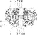
图3显示按图2设置在车辆动力系统的驱动车轴的区域中的横向分动器的横截面图;FIG. 3 shows a cross-sectional view of the transverse transfer case arranged in the region of the drive axle of the vehicle powertrain according to FIG. 2;
图4显示在运行时间t上按图1或图2的车辆动力系统的不同的运行状态参数的曲线。FIG. 4 shows curves of various operating state parameters of the vehicle powertrain according to FIG. 1 or FIG. 2 over an operating time t.
具体实施方式Detailed ways
图1显示车辆动力系统1的示意图,该车辆动力系统具有驱动装置2、变速器3和从动装置4,该从动装置当前包括两个驱动车轴5、6。在此,在图中,车轴5是后轴并且车轴6是前轴。当然根据相应当前的应用情况,由技术人员决定,车轴5可以构成为车辆前轴并且车轴6可以构成为车辆后轴。FIG. 1 shows a schematic diagram of a
在变速器3的区域中,当前,多个用于前进行驶的传动比和至少一个用于倒退行驶的传动比能被构成,变速器3又能构成为有级自动变速器,或者也能构成为无级变速器。驱动装置2在变速器输入轴7的区域中与变速器3作用连接,而变速器3通过变速器输出轴8和与该变速器输出轴作用连接的万向轴12与后轴5的横向分动器9耦联。附加地,驱动装置2能通过摩擦锁合的切换元件10与车辆前轴6的横向分动器11处于作用连接,该切换元件10下面也称为全轮离合器,以便由驱动装置2相应提供的驱动力矩以0~50%分配度朝可驱动的前轴6的方向引导,该驱动力矩相应根据在变速器3区域中接合的或调节的传动比以相应转换的形式施加在变速器输出轴8的区域中。这意味着,根据相应在摩擦锁合的切换元件10的区域中调节的传递能力,在驱动装置2的区域中产生的驱动力矩在50%与100%之间由变速器输出轴8朝后轴5的方向传递。In the area of the
变速器输出轴8与切换元件10的一个切换元件半部耦联,而摩擦锁合的切换元件10的另一个切换元件半部通过基本上在车辆纵向方向上延伸的轴13与前轴6的横向分动器11连接。车轮驱动轴16A、16B在横向分动器11与车轮6A、6B之间延伸,通过所述车轮驱动轴,施加在横向分动器11的区域中的转矩在车辆横向方向上朝车轮6A和6B的方向传递。在相同范围中,通过万向轴12输送至横向分动器9的转矩通过车轮驱动轴15A、15B在车辆横向方向上输送至后轴5的车轮5A、5B,以便能在期望的范围中驱动构成有车辆动力系统1的车辆。The
后轴5的车轮5A、5B以及前轴6的车轮6A、6B的转速通过在车轮5A至6B区域中的转速传感器在测量技术上得出,变速器输出轴8的转速当前通过在车轮5A和5B的区域中求得的后轴5的转速以及横向分动器9的传动比进行计算。在此,由车轮5A和5B的转速确定平均转速,在该平均转速的基础上得出变速器输出轴8的转速。The rotational speeds of the
图2显示车辆动力系统21的另一实施形式,该车辆动力系统同样构成有驱动装置22、变速器23和从动装置24。不同于车辆动力系统1,从动装置24仅包括一个驱动车轴25,该车轴又称为后轴。另一车轴26在当前观察的实施例中是前轴,车轴26不能通过驱动装置22驱动,但是在与车辆动力系统1的前轴6相同的范围中可转向地构成。FIG. 2 shows a further embodiment of a
在后轴25的区域中设置图3详细显示的横向分动器29,该横向分动器29在冠状齿轮或齿轮32的区域中与变速器23的变速器输入轴27作用连接。横向分动器29的齿轮32或冠状齿轮与差速器壳33抗转动地连接,与平衡锥齿轮34A、34B抗转动地连接。锥齿轮35A、35B与平衡锥齿轮34A、34B啮合,所述锥齿轮35A、35B又与在车辆横向方向上延伸的车轮驱动轴36A、36B抗转动地连接。车轮驱动轴36A和36B在车辆横向方向上在横向分动器29与后轴25的车轮25A、25B之间延伸。在冠状齿轮32与车轮驱动轴36B之间设置摩擦锁合的切换元件30,通过该切换元件,冠状齿轮32能与车轮驱动轴36B抗转动地连接。In the region of the
摩擦锁合的切换元件30当前是受调节的横向闭锁器,通过该横向闭锁器,包含差速器的横向分动器29的平衡功能可无级地降低,直至后轴25具有刚性轴的功能并且车轮25A和25B以相同的转速转动。The frictionally engaged shifting
车轮25A和25B的转速当前通过设置在车轮25A和25B的区域中的车轮传感器按本身已知的方式在测量技术上得出,并且另外用于确定与横向分动器29作用连接的变速器输出轴28的转速。The rotational speeds of the
不仅在万向轴12的区域中的断裂而且在车轮驱动轴15A或15B区域中的断裂导致,处于变速器输出轴8上的转矩不再能在车辆动力系统1的车轮5A和5B的区域中被支撑。在这种功能失灵的情况下,所有由驱动装置2提供的驱动力矩乘以当前在变速器3中调节的传动比,施加在摩擦锁合的切换元件10的与变速器输出轴8作用连接的切换元件半部上。The fracture not only in the area of the
因为摩擦锁合的切换元件基于结构空间和成本原因不设计用于,在相应在变速器3中接合的传动比的情况下施加的高转矩可以朝前轴6的方向持久地且完全地传递,并且通过在车轮侧或从动侧确定变速器输出轴8的转速不能得出在车辆动力系统1的区域中的上述功能失灵,所以摩擦锁合的切换元件10随着运行时间的增加也许遭受不期望的高的功率输入,该功率输入可能造成在摩擦锁合的切换元件10的区域中不可逆的损害。Since the friction-locking shifting element is not designed for reasons of installation space and costs, the high torques that are exerted with the respective gear ratios engaged in the
如果车轮驱动轴36A或者车轮驱动轴36B断裂并且变速器23的变速器输出轴28的施加在冠状齿轮32上的转矩在摩擦锁合的切换元件30闭合时按本身已知的方式不再能在后轴25的车轮25A和25B的区域中被支撑,那么也可能产生在横向分动器29的摩擦锁合的切换元件30的区域中不可逆的损害。为了避免在车辆动力系统24的区域中在刚刚说明的功能失灵的情况下的这种运行状态,将摩擦锁合的切换元件30的传递能力提高,并且由变速器输出轴28导入到横向分动器29的转矩通过仍能完全正常运行的车轮驱动轴36A或36B朝车轮25A或25B的方向引导。If the
因为横向分动器29的摩擦锁合的切换元件30从经济角度来看并且也为了限制横向分动器29的结构空间需求而仅仅构成有限的工作能力,所以可能性在于,在相应高的牵引力供应时,在摩擦锁合的切换元件30的区域中,随着运行时间的增加而产生不可逆的损害。这在车轮驱动轴36A或36B的区域中的这种功能失灵期间被促进,因为所述功能失灵不能通过在从动侧得出变速器输出轴8的转速而被识别。Since the frictionally engaged shifting
由于在故障情况下不允许地高的并且通过变速器输出轴8或28施加在摩擦锁合的切换元件10或30上的转矩,摩擦锁合的切换元件10或30打滑地运行。这种打滑运行随着运行时间的增加导致在摩擦锁合的切换元件10或30的区域中运行温度的可能不允许的升高。为了避免在摩擦锁合的切换元件10或30的区域中的损害,并且同时为了在尽可能小的范围中影响构成有车辆动力系统1或21的车辆的可用性,建议下面借助于车辆动力系统1更详细说明的处理方式,在该处理方式期间,除了在从动侧确定变速器输出轴8的转速之外,变速器输出轴8的转速也根据变速器输入轴7的转速乘以当前在变速器3中调节的传动比得出。紧接着,把在从动侧确定的变速器输出轴8的转速与在变速器输入侧得出的变速器输出轴8的转速加以比较。Due to the impermissibly high torques which are exerted on the frictional shifting
在变速器输出轴8的从动侧的转速与变速器输入侧的转速之间的转速差△n8大于阈值时,得出在变速器输出轴8与车轮5A、5B之间的功率流中的功能失灵。转速差△n8可以根据在车轮5A、5B的区域中在从动侧得出的变速器输出轴8的转速和在变速器输入侧得出的变速器输出轴8的转速来确定。在此,变速器输入轴的转速可以通过变速器输入轴传感器或者通过发动机转速传感器得出。If the rotational speed difference Δn8 between the rotational speed of the output side of the
在车辆动力系统1的运行状态过程期间,在时刻T1探测到上面提到的功能失灵,该运行状态过程基于车辆动力系统1的不同的运行参数的在图4中显示的曲线。因为在时刻T1的转速差△n8超过了阈值△n8schwell,所以首先开始时间监控t△n8a,并且直至时刻T2检测,是否转速差△n8在预定义的时间段期间大于阈值△n8schwell。The above-mentioned malfunction is detected at point in time T1 during an operating state course of the
在时刻T2满足这种要求。摩擦锁合的切换元件10的运行温度TE10在时刻T2小于界限值TE10grenz,所以车辆动力系统1继续在所要求的范围中运行。随着运行时间t的增加,摩擦锁合的切换元件10的运行温度TE10上升并且在时刻T3达到界限值TE10grenz。这导致,变速器保护功能被激活,该变速器保护功能的激活状态在图4中通过曲线GSM以图形描述。在时刻T3,曲线GSM从激活值0跳跃到激活值1。附加地,曲线ME也从状态值0变换到状态值1,这又触发了发动机干预并且引起随之而来地将驱动装置2的驱动力矩限制于可应用的转矩值,在该转矩值上,到摩擦锁合的切换元件10中的功率输入被限制,使得可靠地避免摩擦锁合的切换元件10的持久损害。驱动装置2的转矩的限制导致,不仅转速差△n8而且运行温度TE10都具有从时刻T3开始描述的曲线。This requirement is satisfied at time T2. The operating temperature TE10 of the frictionally engaged shifting
在另一时刻T4,运行温度TE10到达另一界限值TE10grenz1。该结果导致,开始另一时间监控t△n8b,并且监控,是否运行温度TE10在预定义的另一时间段上(在此,该时间段在时刻T5结束)持久地低于所述另一界限值TE10grenz1。因为这个检验准则在此在时刻T5被满足,所以变速器保护模式GSM结束,因此,曲线GSM又从激活值1跳跃到激活值0。同时,发动机干预也在时刻T5结束,所以曲线ME也从状态值1返回到状态值0。At another point in time T4, the operating temperature TE10 reaches another limit value TE10grenz1. As a result, a further time monitoring tΔn8b is started and it is monitored whether the operating temperature TE10 is permanently below the further limit for a predefined further time period (here, this time period ends at the time point T5 ) Value TE10grenz1. Since this test criterion is fulfilled here at time T5, the transmission protection mode GSM ends, and the curve GSM jumps from the
用于限制到摩擦锁合的切换元件10或全轮离合器中的功率输入的上述处理方式能在相同范围中用于限制到横向分动器29的摩擦锁合的切换元件30中的功率输入。在此又计算,在摩擦锁合的切换元件30的区域中,在从动侧根据在车轮25A、25B的区域中得出的车轮转速确定的变速器输出轴28的转速与根据变速器输入轴27和在变速器23的区域中调节的传动比在变速器输入侧得出的变速器输出轴28的转速之间的转速差△n28。如果转速差△n28又超过阈值△n28schwell,那么在上述范围中又在时刻T1开始时间监控t△n28a,并且检验,是否转速差△n28在可应用的时间段上超过界限值△n28schwell。在检测结果为肯定时,附加地检验,是否摩擦锁合的切换元件30的运行时间TE30超过界限值TE30grenz。如果也满足这种前提条件,那么变速器保护模式GSM又被激活,并且同时执行发动机干预,以便由驱动装置22提供的驱动力矩限制于可应用的值,在该可应用的值时,避免摩擦锁合的切换元件30的不允许的负载。The above-described procedures for limiting the power input into the frictionally engaged shifting
如果摩擦锁合的切换元件30的运行温度TE30在可通过另一时间监控t△n28b监控的可应用的时间段上低于另一界限值TE30grenz1,那么变速器保护模式GSM并且通过其触发的发动机干预同样在上述范围中被撤回或解除。当前在时刻T5是这种情况。If the operating temperature TE30 of the frictionally engaged shifting
附加地,可能性在于,在定义的行驶情况期间,例如在变速器3、23的运行状态(“空挡”)中,隐没转速差△n8、△n28的可信度检验,以避免错误地检测转速差△n8、△n28,在该运行状态期间,在变速器3、23的区域中力流中断。In addition, it is possible to hide the plausibility check of the rotational speed differences Δn8, Δn28 during defined driving situations, for example in the operating state (“neutral”) of the
另外,在已知的功能失灵时存在如下可能性:在变速器控制器中进行错误输入,并且除了上述的变速器保护措施之外还设定在车辆组合仪表中的报警,以便向驾驶员通知功能失灵并且允许以预定的力矩操纵全轮离合器。In addition, in the event of a known malfunction, there is the possibility of making an erroneous input in the transmission controller and, in addition to the above-mentioned transmission protection measures, setting a warning in the vehicle instrument cluster in order to inform the driver of the malfunction And allows the all-wheel clutch to be operated with a predetermined torque.
总体而言,也存在如下可能性:在识别到不允许地高的负载、优选热负载时,将摩擦锁合的切换元件转换到完全断开的运行状态。Overall, it is also possible to switch the frictionally engaged switching element into a completely disconnected operating state when an impermissibly high load, preferably a thermal load, is detected.
附图标记列表List of reference signs
1 车辆动力系统1 Vehicle power system
2 驱动装置2 drives
3 变速器3 tranny
4 从动装置4 Slave
5 车轴、后轴5 axles, rear axle
5A、5B 车轮5A, 5B Wheels
6 车轴、前轴6 axles, front axle
6A、6B 车轮6A, 6B Wheels
7 变速器输入轴7 Transmission input shaft
8 变速器输出轴8 Transmission output shaft
9 横向分动器9 Lateral transfer case
10 摩擦锁合的切换元件10 Frictionally engaged switching element
11 横向分动器11 Lateral transfer case
12 万向轴12 Cardan shaft
13 轴13 axes
15A、15B 车轮驱动轴15A, 15B Wheel drive shaft
16A、16B 车轮驱动轴16A, 16B Wheel drive shaft
21 车辆动力系统21 Vehicle Powertrain
22 驱动装置22 Drive
23 变速器23 Transmission
24 从动装置24 Slave
25 车轴、后轴25 axle, rear axle
25A、25B 车轮25A, 25B Wheels
26 车轴、前轴26 axles, front axle
27 变速器输入轴27 Transmission input shaft
28 变速器输出轴28 Transmission output shaft
29 横向分动器29 Lateral transfer case
30 摩擦锁合的切换元件30 Frictionally engaged switching elements
32 齿轮、冠状齿轮32 gears, crown gears
33 差速器壳33 Differential housing
34A、34B 平衡锥齿轮34A, 34B Balance Bevel Gears
35A、35B 锥齿轮35A, 35B Bevel Gears
36A、36B 车轮驱动轴36A, 36B wheel drive shaft
△n8 转速差△n8 Speed difference
△n8schwell 阈值△n8schwell threshold
t△n8a、t△n8a b 时间监控t△n8a, t△n8a b Time monitoring
△n28 转速差△n28 Speed difference
△n28schwell 阈值△n28schwell threshold
T1~T5 离散的时刻T1~T5 discrete moments
t 运行时间t running time
TE10、TE30 运行温度TE10, TE30 operating temperature
TE10grenz、TE30grenz 阈值TE10grenz, TE30grenz threshold
TE10grenz1、TE30grenz1 另一阈值TE10grenz1, TE30grenz1 another threshold
GSM 变速器保护模式GSM Transmission Protection Mode
ME 发动机干预。ME engine intervention.
Claims (10)
Applications Claiming Priority (3)
| Application Number | Priority Date | Filing Date | Title |
|---|---|---|---|
| DE102016223177.4 | 2016-11-23 | ||
| DE102016223177.4ADE102016223177B4 (en) | 2016-11-23 | 2016-11-23 | Method for operating a vehicle drive train |
| PCT/EP2017/077218WO2018095678A1 (en) | 2016-11-23 | 2017-10-25 | Method for operating a vehicle drive train |
Publications (2)
| Publication Number | Publication Date |
|---|---|
| CN110023123A CN110023123A (en) | 2019-07-16 |
| CN110023123Btrue CN110023123B (en) | 2022-04-08 |
Family
ID=60164717
Family Applications (1)
| Application Number | Title | Priority Date | Filing Date |
|---|---|---|---|
| CN201780072391.XAActiveCN110023123B (en) | 2016-11-23 | 2017-10-25 | Method for operating a vehicle drive train |
Country Status (4)
| Country | Link |
|---|---|
| US (1) | US11117587B2 (en) |
| CN (1) | CN110023123B (en) |
| DE (1) | DE102016223177B4 (en) |
| WO (1) | WO2018095678A1 (en) |
Families Citing this family (2)
| Publication number | Priority date | Publication date | Assignee | Title |
|---|---|---|---|---|
| CN114714902B (en)* | 2021-08-12 | 2025-10-03 | 长城汽车股份有限公司 | Vehicle control method and vehicle |
| CN115027259B (en)* | 2021-11-11 | 2025-08-15 | 长城汽车股份有限公司 | Vehicle overheat protection control method, device and system |
Citations (6)
| Publication number | Priority date | Publication date | Assignee | Title |
|---|---|---|---|---|
| JP2000142152A (en)* | 1998-11-04 | 2000-05-23 | Fuji Heavy Ind Ltd | Four-wheel drive system for vehicles |
| CN1991201A (en)* | 2005-12-28 | 2007-07-04 | 株式会社日立制作所 | Automobile controller, automobile control method and automatic transmission |
| DE102008022939A1 (en)* | 2008-04-14 | 2009-10-15 | Schaeffler Kg | Final drive arrangement of a vehicle with transfer case |
| CN103189673A (en)* | 2010-12-14 | 2013-07-03 | 腓特烈斯港齿轮工厂股份公司 | Method for the operation of a transmission device in a vehicle drive train when a request is made to change gears |
| JP2013170588A (en)* | 2012-02-17 | 2013-09-02 | Yanmar Co Ltd | Transaxle and wheel type work vehicle |
| CN104553777A (en)* | 2013-10-22 | 2015-04-29 | 上海双杰科技有限公司 | Low-cost timely four-drive transfer case |
Family Cites Families (34)
| Publication number | Priority date | Publication date | Assignee | Title |
|---|---|---|---|---|
| GB1366986A (en)* | 1972-02-15 | 1974-09-18 | Gkn Transmissions Ltd | Self propelled vehicles |
| JPS61191434A (en)* | 1985-02-20 | 1986-08-26 | Honda Motor Co Ltd | vehicle drive system |
| DE10033647B4 (en)* | 2000-07-11 | 2006-06-08 | Adam Opel Ag | System for controlling an automatic transmission |
| WO2002025133A1 (en)* | 2000-09-19 | 2002-03-28 | Nissan Motor Co.,Ltd. | Apparatus for estimating clutch temperature |
| US6440041B1 (en)* | 2001-02-08 | 2002-08-27 | Ford Global Technologies, Inc. | Method of controlling engine torque during launch from neutral idle operation |
| DE10111257B4 (en)* | 2001-03-09 | 2013-10-31 | Burani Consulting Limited Liability Company | Automotive powertrain |
| JP3642041B2 (en)* | 2001-06-26 | 2005-04-27 | 日産自動車株式会社 | Driving force control device for four-wheel drive vehicle |
| JP4192631B2 (en)* | 2003-02-28 | 2008-12-10 | 株式会社ジェイテクト | Torque distribution control device for four-wheel drive vehicles |
| US7630812B2 (en)* | 2004-02-09 | 2009-12-08 | Ford Global Technologies, Llc | Method and system for controlling a transfer case clutch to protect against excessive heat |
| AT8907U1 (en)* | 2005-07-29 | 2007-02-15 | Magna Drivetrain Ag & Co Kg | DISTRIBUTION GEAR WITH TWO NON-INDEPENDENT COUPLINGS FOR CONTROLLING THE MOMENT DISTRIBUTION TO TWO AXES, CLUTCH FOR SUCH AND METHOD FOR CALIBRATION THEREOF |
| CN101516706B (en)* | 2006-09-12 | 2013-01-23 | 丰田自动车株式会社 | Vehicle drive force control device |
| JP2008247251A (en)* | 2007-03-30 | 2008-10-16 | Toyota Motor Corp | POWER OUTPUT DEVICE, ITS CONTROL METHOD, VEHICLE, AND DRIVE DEVICE |
| DE102008043963B4 (en) | 2008-11-21 | 2021-08-12 | Zf Friedrichshafen Ag | Method for operating a drive train |
| DE112009004352T5 (en)* | 2009-01-08 | 2012-06-21 | Toyota Jidosha Kabushiki Kaisha | Control device for a power transmission system of a motor vehicle with four-wheel drive |
| JP5442302B2 (en)* | 2009-04-02 | 2014-03-12 | 本田技研工業株式会社 | Driving force distribution device |
| DE102009032265A1 (en)* | 2009-07-08 | 2011-01-13 | Magna Powertrain Ag & Co Kg | Method for protecting wheel coupling, involves arranging wheel coupling in drive train of motor vehicle, where failure of sensors, is determined, and substitute value is determined for rotation speed value of utilization factor |
| US9605740B2 (en)* | 2009-10-01 | 2017-03-28 | Ford Global Technologies, Llc | Control of an electronic locking differential |
| FR2958584B1 (en)* | 2010-04-12 | 2015-02-20 | Renault Sas | METHOD FOR ALLOYING A SLIDE OF A COUPLER. |
| FR2958607B1 (en)* | 2010-04-12 | 2012-03-23 | Renault Sa | TORQUE DISTRIBUTION CONTROL METHOD FOR A MOTORIZED MOTOR VEHICLE WITH FOUR WHEELS AND CORRESPONDING VEHICLE |
| DE102011006166B4 (en)* | 2011-03-25 | 2020-05-07 | Bayerische Motoren Werke Aktiengesellschaft | Method and control device with a function for protecting an all-wheel clutch of a motor vehicle with clutch-controlled all-wheel drive in a critical brake situation with clutch slip |
| DE102011006168B4 (en)* | 2011-03-25 | 2022-05-12 | Bayerische Motoren Werke Aktiengesellschaft | 4WD clutch protection method and controller having a 4WD clutch protection function |
| GB2492765A (en)* | 2011-07-11 | 2013-01-16 | Jaguar Cars | Hybrid vehicle controller verifies that engine torque corresponds to demanded torque |
| KR20130065169A (en)* | 2011-12-09 | 2013-06-19 | 현대자동차주식회사 | Inter differential lock system |
| JP5585598B2 (en)* | 2012-02-03 | 2014-09-10 | 株式会社アドヴィックス | Vehicle control device |
| CN104114837B (en)* | 2012-02-16 | 2016-08-24 | 日产自动车株式会社 | Car body damping control device |
| JP5799873B2 (en)* | 2012-03-29 | 2015-10-28 | アイシン・エィ・ダブリュ株式会社 | Control device for hybrid vehicle |
| US8523737B1 (en)* | 2012-07-11 | 2013-09-03 | Ford Global Technologies, Llc | All-wheel-drive disconnect clutch control |
| US9573463B2 (en)* | 2013-05-17 | 2017-02-21 | Ford Global Technologies, Llc | Transmission having selectable power transfer shaft |
| JP6241592B2 (en) | 2013-05-17 | 2017-12-06 | スズキ株式会社 | Vehicle driving force distribution control device |
| JP6052110B2 (en)* | 2013-08-30 | 2016-12-27 | アイシン精機株式会社 | Engine control device |
| JP6413454B2 (en)* | 2014-08-07 | 2018-10-31 | 株式会社ジェイテクト | Control device and control method for differential limiting device |
| CN107208716B (en)* | 2015-02-17 | 2019-10-01 | 本田技研工业株式会社 | Oil pressure control device for power distribution device |
| JP6922573B2 (en)* | 2017-09-12 | 2021-08-18 | 株式会社ジェイテクト | Driving force transmission control device |
| US10662884B2 (en)* | 2018-01-17 | 2020-05-26 | Magna Powertrain Of America, Inc. | Power transfer system with clutch protection through interaction with other vehicle systems |
- 2016
- 2016-11-23DEDE102016223177.4Apatent/DE102016223177B4/enactiveActive
- 2017
- 2017-10-25USUS16/462,002patent/US11117587B2/enactiveActive
- 2017-10-25CNCN201780072391.XApatent/CN110023123B/enactiveActive
- 2017-10-25WOPCT/EP2017/077218patent/WO2018095678A1/ennot_activeCeased
Patent Citations (6)
| Publication number | Priority date | Publication date | Assignee | Title |
|---|---|---|---|---|
| JP2000142152A (en)* | 1998-11-04 | 2000-05-23 | Fuji Heavy Ind Ltd | Four-wheel drive system for vehicles |
| CN1991201A (en)* | 2005-12-28 | 2007-07-04 | 株式会社日立制作所 | Automobile controller, automobile control method and automatic transmission |
| DE102008022939A1 (en)* | 2008-04-14 | 2009-10-15 | Schaeffler Kg | Final drive arrangement of a vehicle with transfer case |
| CN103189673A (en)* | 2010-12-14 | 2013-07-03 | 腓特烈斯港齿轮工厂股份公司 | Method for the operation of a transmission device in a vehicle drive train when a request is made to change gears |
| JP2013170588A (en)* | 2012-02-17 | 2013-09-02 | Yanmar Co Ltd | Transaxle and wheel type work vehicle |
| CN104553777A (en)* | 2013-10-22 | 2015-04-29 | 上海双杰科技有限公司 | Low-cost timely four-drive transfer case |
Non-Patent Citations (1)
| Title |
|---|
| 浅谈汽车轴间粘性离合器匹配研究;杨乐肖等;《中小企业管理与科技(下旬刊)》;20151025(第10期);第268页* |
Also Published As
| Publication number | Publication date |
|---|---|
| DE102016223177A1 (en) | 2018-05-24 |
| DE102016223177B4 (en) | 2021-06-17 |
| US20190322278A1 (en) | 2019-10-24 |
| WO2018095678A1 (en) | 2018-05-31 |
| US11117587B2 (en) | 2021-09-14 |
| CN110023123A (en) | 2019-07-16 |
Similar Documents
| Publication | Publication Date | Title |
|---|---|---|
| CN101828053B (en) | Fault detection method for motor vehicle gearbox | |
| US20070111856A1 (en) | Hill hold for a vehicle | |
| US9663109B2 (en) | Vehicle clutch control method | |
| US9187075B2 (en) | Protection of an all-wheel clutch of a motor vehicle having a clutch-controlled all-wheel drive during a critical power braking situation including a clutch slip | |
| KR101755478B1 (en) | Appartus for controlling hybrid vehicle having eop and method thereof | |
| US9382992B2 (en) | Control of locking differential | |
| CN110023123B (en) | Method for operating a vehicle drive train | |
| CN111356619A (en) | Hybrid powertrain system and operation with transfer case in low gear | |
| JP2010508489A (en) | How to drive a car | |
| CN105960556B (en) | Method for preventing motor vehicle from sliding | |
| US7559873B2 (en) | Resolving tie-up in a clutch-to-clutch transmission | |
| US11364799B2 (en) | Torque control device for four-wheel-drive vehicle | |
| JP4449870B2 (en) | Failure detection device for wheel speed sensor | |
| US10336339B2 (en) | Method for controlling a powertrain | |
| US9169925B2 (en) | Method for terminating a gearshift for an automatic transmission for a motor vehicle wherein at least one positive-locking shifting element is involved | |
| US10436262B2 (en) | Control device for power transmission mechanism | |
| SE1950587A1 (en) | Control device and method for controlling a vehicle powertrain to overcome, or avoid, a cog-to-cog condition, computer program, computer-readable medium and vehicle | |
| KR101941230B1 (en) | Method and apparatus for detecting drive derection of transmission | |
| CN108437994B (en) | Method for operating a drive system of a vehicle in a sport mode | |
| JP6268982B2 (en) | Drive control device for four-wheel drive vehicle | |
| US20170313185A1 (en) | Method for operating a multi-axle powertrain for a motor vehicle, and corresponding multi-axle powertrain | |
| SE1150009A1 (en) | Method and clutch actuator control unit for controlling the torque transmission on a powertrain for a vehicle | |
| JP5486433B2 (en) | Engine brake control device | |
| JP6540559B2 (en) | Vehicle control device | |
| JP5538117B2 (en) | Engine brake control device |
Legal Events
| Date | Code | Title | Description |
|---|---|---|---|
| PB01 | Publication | ||
| PB01 | Publication | ||
| SE01 | Entry into force of request for substantive examination | ||
| SE01 | Entry into force of request for substantive examination | ||
| GR01 | Patent grant | ||
| GR01 | Patent grant |