CN110022472B - Stereoscopic display with addressable focus cues - Google Patents
Stereoscopic display with addressable focus cuesDownload PDFInfo
- Publication number
- CN110022472B CN110022472BCN201910196858.2ACN201910196858ACN110022472BCN 110022472 BCN110022472 BCN 110022472BCN 201910196858 ACN201910196858 ACN 201910196858ACN 110022472 BCN110022472 BCN 110022472B
- Authority
- CN
- China
- Prior art keywords
- eyepiece
- optical
- microdisplay
- display
- lens group
- Prior art date
- Legal status (The legal status is an assumption and is not a legal conclusion. Google has not performed a legal analysis and makes no representation as to the accuracy of the status listed.)
- Active
Links
Images


Classifications
- G—PHYSICS
- G02—OPTICS
- G02B—OPTICAL ELEMENTS, SYSTEMS OR APPARATUS
- G02B30/00—Optical systems or apparatus for producing three-dimensional [3D] effects, e.g. stereoscopic images
- G—PHYSICS
- G02—OPTICS
- G02B—OPTICAL ELEMENTS, SYSTEMS OR APPARATUS
- G02B17/00—Systems with reflecting surfaces, with or without refracting elements
- G02B17/08—Catadioptric systems
- G02B17/0856—Catadioptric systems comprising a refractive element with a reflective surface, the reflection taking place inside the element, e.g. Mangin mirrors
- G02B17/086—Catadioptric systems comprising a refractive element with a reflective surface, the reflection taking place inside the element, e.g. Mangin mirrors wherein the system is made of a single block of optical material, e.g. solid catadioptric systems
- H—ELECTRICITY
- H04—ELECTRIC COMMUNICATION TECHNIQUE
- H04N—PICTORIAL COMMUNICATION, e.g. TELEVISION
- H04N13/00—Stereoscopic video systems; Multi-view video systems; Details thereof
- H04N13/30—Image reproducers
- G—PHYSICS
- G02—OPTICS
- G02B—OPTICAL ELEMENTS, SYSTEMS OR APPARATUS
- G02B27/00—Optical systems or apparatus not provided for by any of the groups G02B1/00 - G02B26/00, G02B30/00
- G02B27/01—Head-up displays
- G02B27/0101—Head-up displays characterised by optical features
- G—PHYSICS
- G02—OPTICS
- G02B—OPTICAL ELEMENTS, SYSTEMS OR APPARATUS
- G02B27/00—Optical systems or apparatus not provided for by any of the groups G02B1/00 - G02B26/00, G02B30/00
- G02B27/01—Head-up displays
- G02B27/017—Head mounted
- G02B27/0172—Head mounted characterised by optical features
- G—PHYSICS
- G02—OPTICS
- G02B—OPTICAL ELEMENTS, SYSTEMS OR APPARATUS
- G02B27/00—Optical systems or apparatus not provided for by any of the groups G02B1/00 - G02B26/00, G02B30/00
- G02B27/10—Beam splitting or combining systems
- G02B27/106—Beam splitting or combining systems for splitting or combining a plurality of identical beams or images, e.g. image replication
- G—PHYSICS
- G02—OPTICS
- G02B—OPTICAL ELEMENTS, SYSTEMS OR APPARATUS
- G02B30/00—Optical systems or apparatus for producing three-dimensional [3D] effects, e.g. stereoscopic images
- G02B30/20—Optical systems or apparatus for producing three-dimensional [3D] effects, e.g. stereoscopic images by providing first and second parallax images to an observer's left and right eyes
- G02B30/22—Optical systems or apparatus for producing three-dimensional [3D] effects, e.g. stereoscopic images by providing first and second parallax images to an observer's left and right eyes of the stereoscopic type
- H—ELECTRICITY
- H04—ELECTRIC COMMUNICATION TECHNIQUE
- H04N—PICTORIAL COMMUNICATION, e.g. TELEVISION
- H04N13/00—Stereoscopic video systems; Multi-view video systems; Details thereof
- H04N13/30—Image reproducers
- H04N13/332—Displays for viewing with the aid of special glasses or head-mounted displays [HMD]
- H04N13/339—Displays for viewing with the aid of special glasses or head-mounted displays [HMD] using spatial multiplexing
- H—ELECTRICITY
- H04—ELECTRIC COMMUNICATION TECHNIQUE
- H04N—PICTORIAL COMMUNICATION, e.g. TELEVISION
- H04N13/00—Stereoscopic video systems; Multi-view video systems; Details thereof
- H04N13/30—Image reproducers
- H04N13/332—Displays for viewing with the aid of special glasses or head-mounted displays [HMD]
- H04N13/344—Displays for viewing with the aid of special glasses or head-mounted displays [HMD] with head-mounted left-right displays
- G—PHYSICS
- G02—OPTICS
- G02B—OPTICAL ELEMENTS, SYSTEMS OR APPARATUS
- G02B27/00—Optical systems or apparatus not provided for by any of the groups G02B1/00 - G02B26/00, G02B30/00
- G02B27/01—Head-up displays
- G02B27/0101—Head-up displays characterised by optical features
- G02B2027/011—Head-up displays characterised by optical features comprising device for correcting geometrical aberrations, distortion
- G—PHYSICS
- G02—OPTICS
- G02B—OPTICAL ELEMENTS, SYSTEMS OR APPARATUS
- G02B27/00—Optical systems or apparatus not provided for by any of the groups G02B1/00 - G02B26/00, G02B30/00
- G02B27/01—Head-up displays
- G02B27/0101—Head-up displays characterised by optical features
- G02B2027/0132—Head-up displays characterised by optical features comprising binocular systems
- G02B2027/0134—Head-up displays characterised by optical features comprising binocular systems of stereoscopic type
Landscapes
- Physics & Mathematics (AREA)
- General Physics & Mathematics (AREA)
- Optics & Photonics (AREA)
- Engineering & Computer Science (AREA)
- Multimedia (AREA)
- Signal Processing (AREA)
- Lenses (AREA)
- Testing, Inspecting, Measuring Of Stereoscopic Televisions And Televisions (AREA)
- Stereoscopic And Panoramic Photography (AREA)
- Mechanical Light Control Or Optical Switches (AREA)
- Liquid Crystal (AREA)
- Details Of Television Scanning (AREA)
Abstract
Translated fromChinese
Description
Translated fromChinese本申请是国家申请号为201380054355.2的发明专利申请的分案申请,该发明专利申请的申请日为2013年10月17日,发明名称为“具有可寻址焦点提示的立体显示器”。This application is a divisional application of the invention patent application with the national application number 201380054355.2. The application date of the invention patent application is October 17, 2013, and the invention name is "stereoscopic display with addressable focus prompt".
相关申请Related applications
本申请要求2012年10月18日提交的美国临时申请号61/795,500的优先权的利益,该申请的全部内容被通过引用结合到本文中。This application claims the benefit of priority from US Provisional Application No. 61/795,500, filed October 18, 2012, the entire contents of which are incorporated herein by reference.
政府许可权限government permission
本发明是根据由NSF颁布的IIS0915035在政府支持下完成的。政府对本发明拥有某些权利。This invention was made with government support under IIS0915035 issued by the NSF. The government has certain rights in this invention.
技术领域technical field
本发明一般地涉及立体显示器,并且更特别地、但非排他地涉及具有可寻址焦点提示的立体显示器。The present invention relates generally to stereoscopic displays, and more particularly, but not exclusively, to stereoscopic displays with addressable focus cues.
背景技术Background technique
常规立体3D显示器基于双目视差来创建深度幻觉,在到观察者的固定距离处从一对2D透视图像再现3D场景。因此,常规立体显示器迫使调视和会聚提示的非自然解耦,其可促进立体显示器中的各种视觉伪像,诸如感知深度失真、复视视力、视觉不适以及疲劳。已经提出了许多可克服常规立体显示器的缺点的方法,包括体积(volumetric)显示器、全息显示器和多焦平面显示器。然而,需要开发一种光学透视立体显示器,其解决基本调视——会聚问题,并且还以高图像质量和无闪烁速度再现大体积的连续3D场景。Conventional stereoscopic 3D displays create an illusion of depth based on binocular parallax, reproducing a 3D scene from a pair of 2D perspective images at a fixed distance from the viewer. Thus, conventional stereoscopic displays force an unnatural decoupling of the swept and convergence cues, which can contribute to various visual artifacts in stereoscopic displays, such as perceived depth distortion, diplopia, visual discomfort, and fatigue. A number of approaches have been proposed to overcome the shortcomings of conventional stereoscopic displays, including volumetric displays, holographic displays, and multifocal plane displays. However, there is a need to develop an optical see-through stereoscopic display that addresses the fundamental viewing-convergence problem and also reproduces large-volume continuous 3D scenes with high image quality and flicker-free speed.
具有可寻址焦点提示的立体显示器是解决提供再现用于虚拟3D对象的正确或接近正确的焦点提示的能力的基本调视——会聚问题的最有前途的方法中的一个。不像传统立体显示器,具有可寻址焦点提示的立体显示器使得能够实现根据观看者的感兴趣区通过有源光学元件来动态地改变虚拟显示器的焦距(称为变焦显示模式)或在不需要跟踪观看者的感兴趣区的情况下以无闪烁速度来呈现多个焦平面(称为多焦显示模式)的能力。例如,多焦平面显示器在沿着视轴的多个谨慎放置的离散焦距处呈现透视2D图像。三个离散焦平面将3D场景体积采样成多个区,并且由相应的成对相邻焦平面来再现区内的对象,如图1中所示。因此,多焦平面显示器能够以不同的深度再现用于虚拟对象的正确或接近正确的焦点提示。与诸如全息显示器和体积显示器之类的多视点显示器相反,多焦平面显示器是固定视点显示器。通过限制观看位置,多焦平面显示系统只须显示少量的视点。此外,多交点显示器可以保留常规2D显示器中的视差、遮挡和透视以及再现观看相关照明效果,诸如镜面反射和阴影。特别地,可以将多焦平面显示器的实现分成两类:空间复用或时间复用。在空间复用系统中,通过堆叠多个2D显示器来实现多焦能力。在替换且更精致的时间复用系统中,来自单个2D显示器的图像的焦距被有源光学元件与多个焦平面的帧再现同步地快速切换。一般地,多焦平面显示器可以在没有对光学布局的太多改变的情况下很容易适应于在变焦模式下的使用。Stereoscopic displays with addressable focus cues are one of the most promising approaches to address the fundamental viewing-convergence problem of providing the ability to reproduce correct or near-correct focus cues for virtual 3D objects. Unlike traditional stereoscopic displays, stereoscopic displays with addressable focus cues enable the focal length of the virtual display to be dynamically changed through active optics according to the viewer's region of interest (called zoom display mode) or without the need for tracking. The ability to present multiple focal planes (called multifocal display modes) at flicker-free speeds without the viewer's region of interest. For example, multifocal plane displays present see-through 2D images at multiple carefully placed discrete focal lengths along the viewing axis. Three discrete focal planes sample the 3D scene volume into regions, and objects within the regions are reproduced by corresponding pairs of adjacent focal planes, as shown in FIG. 1 . Thus, a multifocal plane display can reproduce correct or near correct focus cues for virtual objects at different depths. In contrast to multi-view displays such as holographic displays and volumetric displays, multi-focal flat-panel displays are fixed viewpoint displays. By limiting viewing positions, multifocal plane display systems only have to display a small number of viewpoints. In addition, multi-intersection displays can preserve parallax, occlusion, and perspective in conventional 2D displays and reproduce viewing-related lighting effects, such as specular reflections and shadows. In particular, the implementation of multi-focal plane displays can be divided into two categories: spatial multiplexing or temporal multiplexing. In a spatially multiplexed system, multifocal capability is achieved by stacking multiple 2D displays. In an alternative and more refined time multiplexing system, the focal lengths of images from a single 2D display are rapidly switched by active optics in synchronization with frame rendering of multiple focal planes. In general, multifocal flat panel displays can be easily adapted for use in zoom mode without too many changes to the optical layout.
另外,最近已在立体显示器领域取得进展,该立体显示器可以是头部安装的,并且具有可寻址焦平面以用于改善的深度感知,但是与现有方法相比要求基本上更小的计算能力,该现有方法如在其内容被通过引用结合到本文中的共同所有美国专利申请(编号为2011/0075257)中所反映。然而,仍需要能够在具有可寻址焦点提示的立体显示器中提供增强成像性能的光学成像系统。Additionally, recent advances have been made in the area of stereoscopic displays that can be head-mounted and have addressable focal planes for improved depth perception, but require substantially less computation than existing approaches capability, this prior approach is as reflected in commonly owned US patent application Ser. No. 2011/0075257, the contents of which are incorporated herein by reference. However, there remains a need for optical imaging systems that can provide enhanced imaging performance in stereoscopic displays with addressable focus cues.
发明内容SUMMARY OF THE INVENTION
在其方面中的一个中,本发明可提供具有可寻址焦点提示的虚拟显示系统,其包括用于提供虚拟图像以便向用户显示的微型显示器。还可提供被构造成提供可变光学功率的反射有源光学元件。可沿着微型显示器与有源光学元件之间的光学路径设置中继透镜,该中继透镜位于其之间,使得微型显示器和有源光学元件被设置在中继透镜的共轭面处。可以以接收来自有源光学元件的光学辐射的取向沿着微型显示器与有源光学元件之间的光学路径设置分束镜。另外,可提供透视目镜,其包括被构造成接收来自分束镜的光学辐射并将接收辐射反射到系统的出射光瞳以提供虚拟显示路径的选择表面。还可将该选择表面构造成接收来自除微型显示器之外的源(诸如现实世界)的光学辐射并将此类光学辐射透射到出射光瞳以提供透视光学路径。目镜可包括自由形式的棱镜形状,并且特别地,可包括被构造成接收并折射来自分束镜的光学辐射的第一表面,并且可包括被构造成接收来自第一表面的折射光学辐射的第二表面,该第二表面被构造成将光学辐射反射到目镜的选择表面。可将第二表面构造成对光学辐射进行全内反射,并且目镜的表面中的一个或多个可包括旋转不对称表面。In one of its aspects, the present invention may provide a virtual display system with addressable focus cues that includes a microdisplay for providing a virtual image for display to a user. Reflective active optical elements configured to provide variable optical power may also be provided. A relay lens may be positioned along the optical path between the microdisplay and the active optical element with the relay lens therebetween such that the microdisplay and the active optical element are positioned at conjugate planes of the relay lens. Beamsplitters may be positioned along the optical path between the microdisplay and the active optical element in an orientation to receive optical radiation from the active optical element. Additionally, a see-through eyepiece may be provided that includes a selection surface configured to receive optical radiation from the beam splitter and reflect the received radiation to the exit pupil of the system to provide a virtual display path. The selection surface can also be configured to receive optical radiation from sources other than the microdisplay (such as the real world) and transmit such optical radiation to the exit pupil to provide a see-through optical path. The eyepiece may include a free-form prism shape, and in particular, may include a first surface configured to receive and refract optical radiation from the beamsplitter, and may include a first surface configured to receive refracted optical radiation from the first surface. Two surfaces, the second surface being configured to reflect the optical radiation to a selected surface of the eyepiece. The second surface may be configured for total internal reflection of the optical radiation, and one or more of the surfaces of the eyepiece may comprise rotationally asymmetric surfaces.
在其方面中的另一个中,本发明可提供具有可寻址焦点提示的虚拟显示系统,其包括用于提供虚拟图像以便向用户显示的微型显示器以及包括反射光学元件的目镜,该反射光学元件被构造成将来自微型显示器的光学辐射反射到系统的出射光瞳。可沿着微型显示器与目镜之间的光学路径设置中继透镜以将来自微型显示器的图像中继到目镜,该中继透镜包括被构造成提供可变光学功率的折射有源光学元件。中继透镜可包括沿着光学路径设置的第一和第二透镜组,有源光学元件位于第一和第二透镜组之间。另外,可沿着微型显示器与目镜之间的光学路径设置分束镜,该分束镜被构造成接收来自除微型显示器之外的源(诸如现实世界)的光学辐射并将其透射到出射光瞳以提供透视光学路径。目镜可包括球面镜,并且该系统在微型显示器中可以是远心的。该系统还可具有小于3的f数。In another of its aspects, the present invention may provide a virtual display system with addressable focus cues comprising a microdisplay for providing a virtual image for display to a user and an eyepiece comprising reflective optical elements that is configured to reflect optical radiation from the microdisplay to the exit pupil of the system. A relay lens can be positioned along the optical path between the microdisplay and the eyepiece to relay the image from the microdisplay to the eyepiece, the relay lens comprising a refractive active optical element configured to provide variable optical power. The relay lens may include first and second lens groups disposed along the optical path, with the active optical element positioned between the first and second lens groups. Additionally, a beamsplitter can be positioned along the optical path between the microdisplay and the eyepiece, the beamsplitter configured to receive optical radiation from sources other than the microdisplay (such as the real world) and transmit it to the outgoing light pupil to provide a see-through optical path. The eyepiece may comprise a spherical mirror, and the system may be telecentric in a microdisplay. The system may also have f-numbers less than 3.
附图说明Description of drawings
在结合附图来阅读时可进一步理解本发明的示例性实施例的前述发明内容和以下详细描述,在所述附图中:The foregoing summary and the following detailed description of exemplary embodiments of the present invention can be further understood when read in conjunction with the accompanying drawings, in which:
图1示意性地图示出由多个焦平面相对于观看者再现的3D对象;Figure 1 schematically illustrates a 3D object rendered by multiple focal planes relative to a viewer;
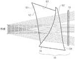
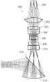
图2示意性地图示出根据本发明的示例性显示系统的折叠光学路径;Figure 2 schematically illustrates the folded optical path of an exemplary display system according to the present invention;
图3A示意性地图示出根据本发明的示例性显示系统的虚拟显示光学器件的2D布局;3A schematically illustrates a 2D layout of virtual display optics of an exemplary display system according to the present invention;
图3B示意性地图示出图3A的示例性显示系统的2D布局,但是具有包括两个光学元件而不是单件的场透镜;Figure 3B schematically illustrates the 2D layout of the exemplary display system of Figure 3A, but with a field lens comprising two optical elements rather than a single piece;
图3C示意性地图示出图3A-3B的自由形式目镜和补偿器,示出了透视光学路径;Figure 3C schematically illustrates the free-form eyepiece and compensator of Figures 3A-3B, showing the see-through optical path;
图3D示意性地示出出图3A-3B的自由形式目镜和补偿器,示出了透视和显示路径两者;Figure 3D schematically illustrates the free-form eyepiece and compensator of Figures 3A-3B, showing both perspective and display paths;
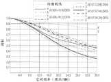
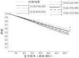
图4A-4E图示出用于图3B的虚拟显示系统的通过显示路径的多色MTF;4A-4E illustrate a multicolor MTF through the display path for the virtual display system of FIG. 3B;
图4F图示出用于图3B的虚拟显示系统的通过显示路径的畸变网格;Figure 4F illustrates a distorted grid through a display path for the virtual display system of Figure 3B;
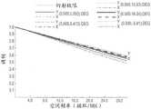
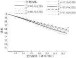
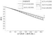
图5A-5E图示出用于图3B的虚拟显示系统的通过透视路径的多色MTF;5A-5E illustrate a multicolor MTF through a see-through path for the virtual display system of FIG. 3B;
图5F图示出用于图3B的虚拟显示系统的通过透视路径的畸变网格;Figure 5F illustrates a distorted grid through perspective paths for the virtual display system of Figure 3B;
图6A示意性地图示出具有图3B的显示系统的中继光学器件的自由形式目镜的3D布局;6A schematically illustrates a 3D layout of a free-form eyepiece with relay optics of the display system of FIG. 3B;
图6B示意性地图示出图6A的显示系统的组装自由形式目镜和补偿器的3DSolidworks模型;Figure 6B schematically illustrates a 3D Solidworks model of the assembled free-form eyepiece and compensator of the display system of Figure 6A;
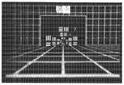
图7A图示出通过用于根据图3B的设计构建的原型的目镜捕捉的40度视场和3屈光度的深度的深度融合6焦平面3D场景;7A illustrates a depth-fused 6 focal plane 3D scene captured by an eyepiece for a prototype built in accordance with the design of FIG. 3B with a 40 degree field of view and a depth of 3 diopters;
图7B-7C图示出用于根据图3B的设计构建的原型的分别地由在2m和30cm处聚焦的照相机捕捉的6焦平面3D场景;Figures 7B-7C illustrate 6 focal plane 3D scenes captured by cameras focused at 2 m and 30 cm, respectively, for a prototype built according to the design of Figure 3B;
图8A图示出与在双焦平面显示器中的眼调节相关的视网膜图像MTF,两个焦平面分别地位于1.2D和1.8D处且具有1:1的辉度比;Figure 8A illustrates retinal image MTF associated with ocular accommodation in a dual focal plane display, the two focal planes being located at 1.2D and 1.8D, respectively, and having a luminance ratio of 1:1;
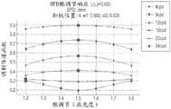
图8B图示出与眼调节相关的视网膜图像对比度,示出了用于不同空间频率的对比度梯度;Figure 8B illustrates retinal image contrast associated with ocular accommodation, showing contrast gradients for different spatial frequencies;
图9A-9B分别地图示出当焦平面间隔增加时和眼瞳尺寸增加时过渡点的空间频率减小;9A-9B illustrate the decrease in spatial frequency of transition points as focal plane separation increases and as pupil size increases, respectively;
图10A、10B分别地示意性地图示出根据本发明的另一示例性显示系统的虚拟显示光学器件的2D和3D布局;Figures 10A, 10B schematically illustrate 2D and 3D layouts, respectively, of virtual display optics of another exemplary display system according to the present invention;
图11示意性地图示出图10A的中继透镜组的2D布局和元件描述以及可选显示照明路径;以及FIG. 11 schematically illustrates the 2D layout and element description of the relay lens group of FIG. 10A and optional display illumination paths; and
图12A、12B分别地图示出图10A-11的系统的多色MTF和场曲线。Figures 12A, 12B illustrate the multicolor MTF and field curves, respectively, of the system of Figures 10A-11.
具体实施方式Detailed ways
现在参考附图,其中,自始至终对相同的元件相同地编号,根据本发明的一个方面,图2示意性地图示出示例性光学系统的一阶未折叠光学路径,该光学系统特别适合于在具有可寻址焦点提示的深度融合多焦平面立体显示器中提供高成像质量。图3A、3B示意性地图示出根据图2的布局的特定设计,第一光学系统100具有单场透镜18,图3A,并且替换系统200具有双元件17、19场透镜18,图3B。(虽然图示出用于单个观看者眼睛的单组光学器件,但应理解的是,在最终立体设备中将提供两组此类光学器件,每只眼睛一个)。Referring now to the drawings, in which like elements are numbered identically throughout, FIG. 2 schematically illustrates a first-order unfolded optical path of an exemplary optical system particularly suitable for High image quality in a Deep Fusion multifocal plane stereo display with addressable focus cues. Figures 3A, 3B schematically illustrate specific designs of the layout according to Figure 2, a first
设计的相关功能包括中继透镜组20,其将来自微型显示器、诸如数字微镜器件(DMD)60的图像中继到目镜12的前面。中继透镜组20可包括传统、不可变形透镜21和反射有源光学元件,诸如可变形薄膜反射镜80,图2。中继透镜21可包括一对双件22、24和透镜26,图3A、3B。可将可变形薄膜反射镜器件(DMMD)80放置在中继透镜21的焦平面上,并且可充当系统止动块。连同图2的透镜21(或透镜22、24、26,图3A、3B)和DMMD 80一起可提供特别适合于深度融合多焦平面立体显示器的折叠双重远心系统。设计双重远心中继器20的优点是DMMD 80上的光学功率的改变仅改变中间图像的位置而不改变图像放大倍率,使得系统的视场和眼空间中的角分辨率保持恒定,并且使得多个焦平面上的相应像素相互一对一地重叠。因此,图3A、3B的设计很好地适合于深度融合技术,而不需要修正否则由不同的图像放大倍率引起的不对准的多个焦图像。通过分析焦点提示和眼调节范围,可进一步理解这些益处。A related function of the design includes a
焦点提示或眼调节范围ΔDaccommodation由下式确定,其意指系统可以再现的3D体积的深度范围The focus cue or eye accommodation range, ΔDaccommodation , is determined by the following equation, which means the depth range of the 3D volume that the system can reproduce

其中,


折叠双重远心中继设计的一个缺点是其不向DMD显示器60的图像提供放大倍率。因此,为了获得期望的系统视场,可在DMD显示器60前面添加场透镜18以将图像放大。(显示器60可以是发射显示器,或者可以是通过照明路径被照亮的反射式显示器)。由场透镜18引入的放大倍率是:One disadvantage of the folded dual telecentric relay design is that it does not provide magnification to the

系统半视场则为:The half field of view of the system is:

基于该设计目标、设备规范以及机械考虑,表1列出了用于图3A、3B的设计的一阶系统规范。Based on the design goals, equipment specifications, and mechanical considerations, Table 1 lists the first-order system specifications for the design of Figures 3A, 3B.
表1. 用于虚拟显示器的一阶系统规范。Table 1. First-order system specifications for virtual displays.
自由形式目镜和补偿器Freeform eyepieces and compensators
可通过使用分束镜来使虚拟显示光学器件(例如,DMD 60、场透镜18、中继透镜组20)折叠到路径之外而实现系统100、200的光学透视能力。然而,给定本设计中的目镜12具有短焦距,按照惯例非常难以设计该系统。The optical see-through capabilities of the
在本示例性设计中,追求更精致的解决方案。如图3C、3D中所示,目镜12被设计为楔形自由形式塑料透镜。自由形式棱镜目镜12可包括分别地标记为S1、S2和S3的三个旋转不对称表面。考虑图3D的虚拟显示路径,来自显示器60的中间图像的光线首先被表面S3折射。在被表面S1和S2两次连续反射之后,光线通过表面S1被透射并到达系统的出射(眼)光瞳。表面S1期望地满足用于在表面S1上反射的所有光线的全内反射的条件。可将目镜12的表面S2涂敷为半反射镜以便促进光学透视能力。可将可包括两个旋转不对称表面S2和S4的自由形式补偿器14接合到目镜12以补偿当两件12、14被组合在一起时(图3C)从现实世界场景引入到光线中的像差和畸变。另外,可在自由形式补偿器14中包括可选圆筒透镜13以帮助使用于透视路径的像差和畸变最小化。In this exemplary design, a more refined solution is pursued. As shown in Figures 3C, 3D, the
为了实现期望光学性能,选择MTF值以评估总体图像锐度。由于虚拟显示系统100是从目镜12至显示器60向后设计的,所以目标是在显示器60上具有在36 lp/mm的空间频率下不超过20%的MTF值,其是用于14μm的像素尺寸的截止频率。人眼具有1 arcmin的角分辨率。因此,补偿器14被优化,使得30循环/度下的MTF值大于0.2而使现实世界场景的退化最小化。系统100、200的另一重要光学性能因数是图像畸变。在常规系统中,畸变是规则的,并且可以容易地以电子方式或以计算方式来补偿。然而,在具有离轴自由形式光学器件的系统中,畸变可能是非常大且不规则的。因此,系统100、200的设计应对在整个FOV上采样的畸变具有严格的约束。该畸变对于透视光学路径而言尤其重要,因为其可以改变通过透视视图看到的对象的尺寸和形状,因此大大地影响3D感知。To achieve the desired optical performance, the MTF value was chosen to evaluate the overall image sharpness. Since the
设计和优化程序Design and optimization procedures
系统100、200的设计涉及到两个步骤,虚拟显示路径和光学透视路径。对于虚拟显示路径而言,在CodeV中用中继透镜20和场透镜18来设定自由形式目镜12并一起优化。显示性能对于跨40度的FOV且跨3屈光度的期望眼调节范围采样的场而言是平衡的。在完成虚拟显示优化之后,用补偿器14单独地设定自由形式目镜12,并且针对透视性能而优化补偿器的背面S4。在强调中央40度的同时针对60度的视场而优化透视性能。通过随着系统性能的改善而逐渐地增加自由形式表面的可变表面系数的数目来在两个步骤中采用渐进式优化策略。The design of the
在最后的设计中,用达到10阶的XY多项式来描述自由形式目镜和补偿器表面S1、S2、S3、S4并用在PMMA上的单点金刚石车削来制作原型。在图3B的系统200中,优化场透镜元件中的一个(透镜17),并添加衍射光学特征以修正由自由形式目镜12引入的色像差。所有其他透镜19、22、24、26全部是成品部件以降低制作原型成本。In the final design, free-form eyepiece and compensator surfaces S1, S2, S3, S4 were described with XY polynomials up to
针对3mm瞳孔评估的虚拟显示器的多色MTF值跨具有0.5的中心场值的40度的视场在36 lp/mm下大于0.2,图4A-4E。虚拟显示器还显示出最小畸变,图4F。针对3mm瞳孔评估的透视光学路径的多色MTF值跨40度的视场在30循环/度下大于0.4,图5A-5E。透视场景的畸变也被很好地修正,图5F。如下提供用于图3B的特定设计的规定。The polychromatic MTF value of the virtual display evaluated for a 3 mm pupil was greater than 0.2 at 36 lp/mm across a 40 degree field of view with a central field value of 0.5, Figures 4A-4E. The virtual display also showed minimal distortion, Figure 4F. The polychromatic MTF values for the fluoroscopy optical path assessed for a 3 mm pupil were greater than 0.4 at 30 cycles/degree across a 40 degree field of view, Figures 5A-5E. The distortion of the perspective scene is also well corrected, Figure 5F. Provisions for the specific design of Figure 3B are provided as follows.
用于虚拟显示路径的系统规定System Provisions for Virtual Display Paths
在表2中,表面#2 - #4指定自由形式目镜12。表面#2和#4表示同一物理表面,并且还表示为目镜表面S1。还将表面#3表示为目镜表面S2,并且还将表面#5表示为目镜表面S3。表面#8 - #15和表面#17 - #24是在双重路径中建模的同一组中继透镜22、24、26。在表面#16处对可变形反射镜80进行建模。表面#25 - #26以45度对分束镜16进行建模。表面#27 -# 28表示场透镜元件17,并且表面#29 - #30表示场透镜元件19。In Table 2, surfaces #2 - #4 designate

表2. 用于虚拟显示路径的系统规定。Table 2. System regulations for virtual display paths.
用于光学透视路径的系统规定System Specifications for Optical Perspective Paths
在表3中,表面#2和#3是目镜表面S1和S3,与在虚拟显示路径中相同地建模。表面#4、#5指定自由形式补偿器14。表面#4是表面#3(目镜表面S3)的精确复制品。In Table 3, surfaces #2 and #3 are eyepiece surfaces S1 and S3, modeled the same as in the virtual display path.

表3. 用于透视路径的系统规定。Table 3. System provisions for perspective paths.
如在例如表2或表3的系统规定表中所使用的术语“XY Poly”指代可用以下等式来表示的表面The term "XY Poly" as used in a system specification table such as Table 2 or Table 3 refers to a surface that can be represented by the following equation

其中,z是沿着本地x、y、z坐标系的z轴测量的自由形式表面的下陷(sag),c是顶点曲率(CUY),r是径向距离,k是圆锥常数,并且Cj是用于xmyn的系数。表中的术语“非球面”指代可用以下等式来表示的非球面表面where z is the sag (sag) of the free-form surface measured along the z-axis of the local x, y, z coordinate system, c is the vertex curvature (CUY), r is the radial distance, k is the conic constant, and Cj are the coefficients for xm yn . The term "aspherical" in the table refers to an aspherical surface that can be represented by the following equation

其中,z是沿着本地x、y、z坐标系的z轴测量的表面的下陷,c是顶点曲率,r是径向距离,k是圆锥常数,A至E分别是4、6、8、10和12阶变形系数。where z is the subsidence of the surface measured along the z-axis of the local x, y, z coordinate system, c is the vertex curvature, r is the radial distance, k is the conic constant, and A to E are 4, 6, 8, Deformation coefficients of

表4. 表2的表面#2和#4的光学表面规定。Table 4. Optical Surface Specifications for
表5. 表2的表面#2和#4相对于表2的表面#1的偏心。Table 5. Eccentricity of

表6. 表2的表面#3的光学表面规定。Table 6. Optical Surface Specifications for
表7. 表2的表面#3相对于表2的表面#1的偏心。Table 7. Eccentricity of

表8. 表2的表面#5的光学表面规定。Table 8. Optical Surface Specifications for
表9. 表2的表面#5相对于表2的表面#1的偏心。Table 9. Eccentricity of
转到第二场透镜元件17的规定,场透镜元件17的两个表面都是非球面表面。另外,场透镜元件17的表面#29(表2)具有可根据以下等式来表示的开诺全息衍射光学特征。Turning to the specification of the second field lens element 17, both surfaces of the field lens element 17 are aspherical surfaces. In addition, the surface #29 (Table 2) of the field lens element 17 has kinographic diffractive optical characteristics that can be expressed according to the following equation.

其中,

表10. 用于表2的表面#29的表面规定。Table 10. Surface Specifications for Surface #29 of Table 2.

表11. 用于表2的表面#29的衍射光学元件相位数据。Table 11. Diffractive optical element phase data for surface #29 of Table 2.

表12. 用于表2的表面#30的表面规定。Table 12. Surface Specifications for

表13. 表3的表面#5的光学表面规定。Table 13. Optical Surface Specifications for
表14. 表面#5相对于表3的表面#1的偏心。Table 14. Eccentricity of
没有圆筒透镜的替换示例性设计Alternative Exemplary Designs Without Cylindrical Lenses
在以上图3A、3B的设计中,在自由形式补偿器14中已包括可选圆筒透镜13以帮助使像差和畸变最小化。还提供了没有圆筒透镜13的替换设计,其中,虚拟显示路径与图3B和表2中所示的相同。在不存在圆筒透镜13的情况下的透视路径的其余表面的唯一差别是目镜/补偿器表面S2(表3的光学透视路径中的表面#5)。在表15中,表面#2和#3是目镜表面S1和S3,与在虚拟显示路径中相同地建模。表面#4-5描述了自由形式补偿器14。表面#4是表面#3的精确复制品。In the designs of Figures 3A, 3B above, an optional

表15. 没有圆筒透镜的替换目镜光学器件规定。Table 15. Specifications for replacement eyepiece optics without cylindrical lenses.

表16. 表15的表面#5的光学表面规定。Table 16. Optical Surface Specifications for
表17. 表15的表面#5相对于表15的表面#1的偏心。Table 17. Eccentricity of
图3B的系统的原型Prototype of the system of Figure 3B
图3B的多焦平面显示系统200的原型构建有在图6A、6B中提供了其3D视图的成品透镜和自定义光学器件。系统200被折叠以避免与观看者的头部碰撞。还开发了自定义电子装置以控制DMD 60(挪威德拉曼VISITECH的LUXBEAM® 4500)上的显示图像、LED(未示出)的照明以及可变形反射镜80(荷兰利兹维克的Flexible Optical B.V.的OKO® TechnologiesMMDM10-1-focus)的焦平面切换并使其同步。The prototype of the multifocal
再现由倾斜平面对象和绿色底板网格组成的连续3D场景,两者从0扩展至2.5屈光度。场景基于目标的深度值而被分解成置于3屈光度、2.4屈光度、1.8屈光度、1.2屈光度、0.6屈光度和0屈光度的6个焦平面,并且使用深度融合技术来将6个焦平面混合成平滑连续流。以约60 Hz刷新整体3D场景;因此,看不见闪烁。图7A示出了通过系统看到的实际6焦平面场景;图像是清楚的,且具有非常低的畸变。在没有特殊算法的情况下,不同焦平面上的像素由于恒定的视场设计而平滑地重叠并融合。另外,使用具有浅场深的照相机透镜并在场景的不同部分处手动地聚焦。在图7B中,在后壁上显示分辨率目标,并且使照相机聚焦在约2m处。底部网格的近端没有对焦,并且背面网格以及徽标处于锐聚焦。在图7C中,在前焦平面上显示分辨率目标,照相机在30 m处聚焦,并且现在近景对焦且背面的内容被模糊。因此,证明原型能够以无闪烁的速度再现高质量、高分辨率彩色图像的6个或更多焦平面。其对于增强现实应用而言具有非常好的光学透视性能,并且具有提供较高深度感知准确度、较高立体感以及较低用户疲劳的潜力。Reproduces a continuous 3D scene consisting of slanted planar objects and a green backplane mesh, both scaled from 0 to 2.5 diopters. The scene is decomposed into 6 focal planes placed at 3, 2.4, 1.8, 1.2, 0.6, and 0 diopter based on the depth value of the target, and a depth fusion technique is used to blend the 6 focal planes into a smooth continuous flow. The overall 3D scene is refreshed at approximately 60 Hz; therefore, no flickering is visible. Figure 7A shows the actual 6 focal plane scene seen through the system; the image is clear with very low distortion. Without special algorithms, pixels on different focal planes smoothly overlap and merge due to the constant field of view design. Alternatively, use a camera lens with a shallow depth of field and focus manually at different parts of the scene. In Figure 7B, the resolution target is displayed on the back wall and the camera is focused at about 2m. The near end of the bottom grid is out of focus, and the back grid as well as the logo are in sharp focus. In Figure 7C, the resolution target is shown on the front focal plane, the camera is focused at 30 m, and the close-up is now in focus and the content on the back is blurred. Thus, the prototype was shown to be able to reproduce 6 or more focal planes of high-quality, high-resolution color images at flicker-free speeds. It has very good optical see-through performance for augmented reality applications and has the potential to provide higher depth perception accuracy, higher stereoscopic perception, and lower user fatigue.
替换示例性可调谐透镜Replacing an Exemplary Tunable Lens
在其另一方面,本发明提供了示例性多焦平面显示系统300,其将诸如硅上液晶(LCOS)和硅上铁电液晶(FLCoS)之类的高速显示技术与诸如电可调谐透镜380之类的高速有源折射光学元件组合。特定设计是基于0.8” WXGA LCOS/FLCOS显示器360和10mm光圈电可调谐透镜380(瑞士Dietikon的Optotune EL-10-30, Optotune AG)。可调谐透镜380在电流流过透镜380而产生光学功率的改变时改变形状。Optotune透镜380具有约2.5ms的响应时间,并且因此潜在地可以在多焦平面显示器中使用;In another of its aspects, the present invention provides an exemplary multi-focal
表18. 用于可调谐透镜系统的设计规范。Table 18. Design specifications for tunable lens systems.
在图10A-11中示出了设计的最终布局。中继透镜组(透镜302、304、306、380、308、310)将图像中继到球面反射镜318,其充当目镜并形成用于用户的虚拟图像。可选地,反射镜318可以是非球面的。使用分束镜316来启用透视能力。可调谐透镜380可提供系统止动块,并且由于LCOS/FLCoS的要求,系统对于微型显示器360而言可以是远心的。还给出了足够的空间以用于照明分束镜317,图11。在表19——表26中提供了系统300的规定。(在表19中,表面#9 - 12对Optotune电可调谐透镜380进行建模)。在图12A、12B中图示出系统的性能。The final layout of the design is shown in Figures 10A-11. The relay lens group (

表19. 可调谐透镜系统规定。Table 19. Tunable Lens System Specifications.

表20. 用于表19的表面#5的表面规定。Table 20. Surface Specifications for

表21. 用于表19的表面#6的表面规定。Table 21. Surface Specifications for

表22. 用于表19的表面#14的表面规定。Table 22. Surface Specifications for

表23. 用于表19的表面#15的表面规定。Table 23. Surface Specifications for

表24. 用于表19的表面#16的表面规定。Table 24. Surface Specifications for

表25. 用于表19的表面#18的表面规定。Table 25. Surface Specifications for

表26. 用于表19的表面#19的表面规定。Table 26. Surface Specifications for
总体设计考虑General Design Considerations
在其另一方面,本发明涉及用于确定深度融合显示(DFD)系统设计参数的新准则。用其视网膜图像的点扩展函数(PSF)或者等价地用调制传递函数(MTF)来量化DFD显示器中的融合像素的光学质量,用视网膜图像的对比度调制与3D显示器上的正弦对象的比来表征所述调制传递函数(MTF)。例如,当眼睛以再现深度z进行眼调节时,可将由分别位于z1和z2处的一对相邻焦平面上的两个像素融合的像素PSF12的PSF描述为来自前面和背面像素的PSF的加权和,如下:In another of its aspects, the present invention relates to new criteria for determining design parameters for Deep Fusion Display (DFD) systems. Quantify the optical quality of a fused pixel in a DFD display by the point spread function (PSF) of its retinal image, or equivalently, by the modulation transfer function (MTF), using the ratio of the contrast modulation of the retinal image to a sinusoidal object on a 3D display Characterize the modulation transfer function (MTF). For example, the PSF of pixel PSF12 fused by two pixels on a pair of adjacent focal planes located at z1 and z2 , respectively, can be described as a The weighted sum of PSFs, as follows:

其中,PSF1(z, z1)和PSF2(z, z2)是眼睛在距离z处进行眼调节时的前面和背面像素的点扩展函数。对等式(1)中的PSF进行归一化,使得前面和背面像素在计算加权和之前具有相同的辉度。w1和w2是对前面和背面像素的辉度进行调制的深度加权融合函数,并且通常实行w1(z) + w2(z) = 1,使得当模拟深度改变时,融合图像的总辉度保持相同。然后可以经由PSF12(z)的傅立叶变换来计算显示器的MTF。where PSF1 (z, z1 ) and PSF2 (z, z2 ) are the point spread functions of the front and back pixels when the eye is accommodating at distance z. The PSF in equation (1) is normalized so that the front and back pixels have the same luminance before calculating the weighted sum. w1 and w2 are depth-weighted fusion functions that modulate the luminance of front and back pixels, and w1 (z) + w2 (z) = 1 is generally implemented so that when the simulated depth changes, the overall fused image is The brightness remains the same. The MTF of the display can then be calculated via the Fourier transform of PSF12 (z).
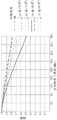
在图8A中示出了双焦平面DFD显示器的模拟视网膜图像的MTF图的示例。在模拟中,两个焦平面被分别地置于1.2屈光度和1.8屈光度,并且两个焦平面之间的辉度比是1:1,指示正在前面和背面焦平面的屈光中点、即1.5屈光度下模拟融合像素。为了会聚在深度融合的效果上,选择具有3mm光瞳的眼睛模型,去除所有残余像差。图8A示出了视网膜图像的MTF如何随着眼睛在两个焦平面之间的各种位置处进行眼调节而改变。图8B示出了作为用于不同空间频率的眼调节距离的函数的对比度梯度,并且用于用黑格标记来标记的每个频率的峰值对比度。从两个图观察约17循环/度(cpd)的过渡频率。在该过渡频率以下,在1.5屈光度的屈光中点下使视网膜图像的MTF最大化,所述MTF为在双焦平面系统中以1:1辉度比模拟的深度。此外,随着眼睛从远或近焦平面接近模拟深度,MTF值平滑地增加,提供驱动眼调节所需的适当对比度梯度。然而,对于高于17 cpd的频率而言,当眼睛在物理焦平面处或其附近调节时,融合像素的对比度始终是最高的,意味着对比度梯度具有驱动眼调节远离模拟像素深度的趋势,因此产生碰撞眼调节提示。An example of an MTF plot of a simulated retinal image of a dual focal plane DFD display is shown in Figure 8A. In the simulation, the two focal planes were placed at 1.2 diopters and 1.8 diopters, respectively, and the luminance ratio between the two focal planes was 1:1, indicating being at the refractive midpoint of the front and back focal planes, ie, 1.5 diopters Simulate fused pixels. In order to focus on the effect of deep fusion, an eye model with a 3mm pupil was chosen, with all residual aberrations removed. Figure 8A shows how the MTF of a retinal image changes as the eye accommodates at various positions between the two focal planes. Figure 8B shows the contrast gradient as a function of ocular accommodation distance for different spatial frequencies, and peak contrast for each frequency marked with a black grid. A transition frequency of about 17 cycles/degree (cpd) was observed from both plots. Below this transition frequency, the MTF of the retinal image, which is the depth simulated with a 1:1 luminance ratio in a bifocal plane system, is maximized at a refractive midpoint of 1.5 diopters. Furthermore, as the eye approaches simulated depth from the far or near focal plane, the MTF value increases smoothly, providing the appropriate contrast gradient needed to drive eye accommodation. However, for frequencies above 17 cpd, the contrast of the fused pixels is always highest when the eye is accommodated at or near the physical focal plane, implying that the contrast gradient has a tendency to drive the eye accommodation away from the simulated pixel depth, so Generate collision eye adjustment prompt.
图9A、9B示出了过渡频率如何作为焦平面间隔的函数和光瞳尺寸的函数而改变。图9A采取3mm眼瞳,并且图9B采取0.6屈光度的恒定焦平面间隔。结果暗示焦平面间隔越小且设计的眼瞳尺寸越小,过渡点处于越高的频率下。因此,用于设计DFD显示器的关键准则是应确定焦平面间隔和显示器的工作光瞳尺寸,使得对比度梯度反向点高于系统的截止频率,以避免向观看者呈现碰撞眼调节提示。例如,可以认为相邻焦平面之间的0.6屈光度间隔适合于DFD显示器,其提供每像素1.8弧分钟的角分辨率(大约17 cpd的空间频率)和大于10 cd/m2的辉度。10 cd/m2显示器辉度的模拟导致约3mm眼瞳直径。对于提供每像素1弧分钟的角分辨率(即,30 cpd)的显示器而言,0.45或更小的屈光度间距将是期望的。每像素的角分辨率越小或者图像亮度越低,期望的焦平面间隔将越小。Figures 9A, 9B show how the transition frequency varies as a function of focal plane separation and as a function of pupil size. Figure 9A assumes a 3 mm pupil, and Figure 9B assumes a constant focal plane separation of 0.6 diopters. The results imply that the smaller the focal plane separation and the smaller the designed pupil size, the higher the frequency of the transition point. Therefore, a key criterion for designing a DFD display is that the focal plane separation and the display's working pupil size should be determined so that the contrast gradient reversal point is above the cutoff frequency of the system to avoid presenting a collision eye accommodation cue to the viewer. For example, a 0.6 diopter separation between adjacent focal planes can be considered suitable for a DFD display that provides an angular resolution of 1.8 arc minutes per pixel (a spatial frequency of approximately 17 cpd) and a luminance greater than 10cd /m2. Simulation of a 10 cd/m2 display luminance results in a pupil diameter of about 3mm. For a display that provides an angular resolution of 1 arc minute per pixel (ie, 30 cpd), a diopter separation of 0.45 or less would be desirable. The smaller the angular resolution per pixel or the lower the image brightness, the smaller the desired focal plane separation will be.
根据先前的说明书,本发明的这些及其他优点对于本领域的技术人员而言将是显而易见的。因此,本领域的技术人员将认识到的是,在不脱离本发明的宽泛发明构思的情况下可对上述实施例进行变更和修改。因此应理解的是,本发明不限于本文所述的特定实施例,而是意图包括在权利要求中所阐述的本发明的范围和精神内的所有变更和修改。These and other advantages of the present invention will be apparent to those skilled in the art from the preceding description. Accordingly, those skilled in the art will recognize that changes and modifications may be made to the above-described embodiments without departing from the broad inventive concept of the invention. It is therefore to be understood that this invention is not limited to the particular embodiments described herein, but it is intended to include all changes and modifications within the scope and spirit of the invention as set forth in the appended claims.
Claims (6)
Applications Claiming Priority (4)
| Application Number | Priority Date | Filing Date | Title |
|---|---|---|---|
| US201261795500P | 2012-10-18 | 2012-10-18 | |
| US61/795500 | 2012-10-18 | ||
| PCT/US2013/065422WO2014062912A1 (en) | 2012-10-18 | 2013-10-17 | Stereoscopic displays with addressable focus cues |
| CN201380054355.2ACN104756494B (en) | 2012-10-18 | 2013-10-17 | Stereoscopic display with addressable focus cues |
Related Parent Applications (1)
| Application Number | Title | Priority Date | Filing Date |
|---|---|---|---|
| CN201380054355.2ADivisionCN104756494B (en) | 2012-10-18 | 2013-10-17 | Stereoscopic display with addressable focus cues |
Publications (2)
| Publication Number | Publication Date |
|---|---|
| CN110022472A CN110022472A (en) | 2019-07-16 |
| CN110022472Btrue CN110022472B (en) | 2022-07-26 |
Family
ID=50488746
Family Applications (2)
| Application Number | Title | Priority Date | Filing Date |
|---|---|---|---|
| CN201910196858.2AActiveCN110022472B (en) | 2012-10-18 | 2013-10-17 | Stereoscopic display with addressable focus cues |
| CN201380054355.2AActiveCN104756494B (en) | 2012-10-18 | 2013-10-17 | Stereoscopic display with addressable focus cues |
Family Applications After (1)
| Application Number | Title | Priority Date | Filing Date |
|---|---|---|---|
| CN201380054355.2AActiveCN104756494B (en) | 2012-10-18 | 2013-10-17 | Stereoscopic display with addressable focus cues |
Country Status (11)
| Country | Link |
|---|---|
| US (4) | US9874760B2 (en) |
| EP (1) | EP2910022B1 (en) |
| JP (3) | JP6525880B2 (en) |
| KR (2) | KR102207298B1 (en) |
| CN (2) | CN110022472B (en) |
| AU (4) | AU2013331179B2 (en) |
| CA (2) | CA2885563C (en) |
| IL (3) | IL276021B2 (en) |
| IN (1) | IN2015DN02476A (en) |
| NZ (3) | NZ739225A (en) |
| WO (1) | WO2014062912A1 (en) |
Families Citing this family (66)
| Publication number | Priority date | Publication date | Assignee | Title |
|---|---|---|---|---|
| GB2468997A (en) | 2008-01-22 | 2010-09-29 | Univ Arizona State | Head-mounted projection display using reflective microdisplays |
| US9866826B2 (en) | 2014-11-25 | 2018-01-09 | Ricoh Company, Ltd. | Content-adaptive multi-focal display |
| US9865043B2 (en) | 2008-03-26 | 2018-01-09 | Ricoh Company, Ltd. | Adaptive image acquisition and display using multi-focal display |
| WO2010123934A1 (en) | 2009-04-20 | 2010-10-28 | The Arizona Board Of Regents On Behalf Of The University Of Arizona | Optical see-through free-form head-mounted display |
| US20110075257A1 (en) | 2009-09-14 | 2011-03-31 | The Arizona Board Of Regents On Behalf Of The University Of Arizona | 3-Dimensional electro-optical see-through displays |
| DE102017203492A1 (en)* | 2017-03-03 | 2018-09-06 | Witec Wissenschaftliche Instrumente Und Technologie Gmbh | Method and device for imaging a sample surface |
| EP2564259B1 (en) | 2010-04-30 | 2015-01-21 | Beijing Institute Of Technology | Wide angle and high resolution tiled head-mounted display device |
| US10156722B2 (en)* | 2010-12-24 | 2018-12-18 | Magic Leap, Inc. | Methods and systems for displaying stereoscopy with a freeform optical system with addressable focus for virtual and augmented reality |
| NZ627582A (en) | 2012-01-24 | 2016-11-25 | Univ Arizona State | Compact eye-tracked head-mounted display |
| CN110022472B (en) | 2012-10-18 | 2022-07-26 | 亚利桑那大学评议会 | Stereoscopic display with addressable focus cues |
| US9699433B2 (en) | 2013-01-24 | 2017-07-04 | Yuchen Zhou | Method and apparatus to produce re-focusable vision with detecting re-focusing event from human eye |
| WO2014144989A1 (en)* | 2013-03-15 | 2014-09-18 | Ostendo Technologies, Inc. | 3d light field displays and methods with improved viewing angle depth and resolution |
| US9857591B2 (en) | 2014-05-30 | 2018-01-02 | Magic Leap, Inc. | Methods and system for creating focal planes in virtual and augmented reality |
| US9915826B2 (en) | 2013-11-27 | 2018-03-13 | Magic Leap, Inc. | Virtual and augmented reality systems and methods having improved diffractive grating structures |
| EP4099274B1 (en) | 2014-01-31 | 2024-03-06 | Magic Leap, Inc. | Multi-focal display system and method |
| CN110376743B (en) | 2014-01-31 | 2022-03-04 | 奇跃公司 | Multi-focus display system and method |
| CA2941655C (en) | 2014-03-05 | 2021-03-09 | Arizona Board Of Regents On Behalf Of The University Of Arizona | Wearable 3d augmented reality display with variable focus and/or object recognition |
| AU2015266670B2 (en)* | 2014-05-30 | 2019-05-09 | Magic Leap, Inc. | Methods and systems for displaying stereoscopy with a freeform optical system with addressable focus for virtual and augmented reality |
| EP3149528B1 (en) | 2014-05-30 | 2023-06-07 | Magic Leap, Inc. | Methods and system for creating focal planes in virtual and augmented reality |
| US9864205B2 (en) | 2014-11-25 | 2018-01-09 | Ricoh Company, Ltd. | Multifocal display |
| IL310369A (en) | 2015-01-26 | 2024-03-01 | Magic Leap Inc | Virtual and augmented reality systems and methods with improved diffractive lattice structures |
| US10176961B2 (en) | 2015-02-09 | 2019-01-08 | The Arizona Board Of Regents On Behalf Of The University Of Arizona | Small portable night vision system |
| US9848127B2 (en)* | 2015-07-14 | 2017-12-19 | Honeywell International Inc. | System and method for a compact display |
| US10204451B2 (en)* | 2015-11-30 | 2019-02-12 | Microsoft Technology Licensing, Llc | Multi-optical surface optical design |
| US20210223738A1 (en)* | 2015-12-28 | 2021-07-22 | Seereal Technologies S.A. | Display device and method for optimizing the image quality |
| AU2017225977C1 (en) | 2016-03-04 | 2023-08-03 | Magic Leap, Inc. | Current drain reduction in AR/VR display systems |
| US10698215B2 (en) | 2016-03-25 | 2020-06-30 | Magic Leap, Inc. | Virtual and augmented reality systems and methods |
| US11067797B2 (en) | 2016-04-07 | 2021-07-20 | Magic Leap, Inc. | Systems and methods for augmented reality |
| CN105929537A (en)* | 2016-04-08 | 2016-09-07 | 北京骁龙科技有限公司 | Head-mounted display and eyepiece system thereof |
| EP3453171A4 (en)* | 2016-05-04 | 2019-12-18 | The Regents of the University of California | LIGHT PSEUDO-FIELD DISPLAY APPARATUS |
| WO2018052590A2 (en) | 2016-08-12 | 2018-03-22 | Arizona Board Of Regents On Behalf Of The University Of Arizona | High-resolution freeform eyepiece design with a large exit pupil |
| JP6964239B2 (en)* | 2016-08-31 | 2021-11-10 | パナソニックIpマネジメント株式会社 | Display device |
| RU2650086C1 (en) | 2016-12-22 | 2018-04-06 | Самсунг Электроникс Ко., Лтд. | Holographic image display device and a method of operation of a control unit contained in it |
| WO2018165123A1 (en)* | 2017-03-09 | 2018-09-13 | Arizona Board Of Regents On Behalf Of The University Of Arizona | Freeform prism and head-mounted display with increased field of view |
| US12078802B2 (en) | 2017-03-09 | 2024-09-03 | Arizona Board Of Regents On Behalf Of The University Of Arizona | Head-mounted light field display with integral imaging and relay optics |
| JP7182796B2 (en) | 2017-03-09 | 2022-12-05 | アリゾナ ボード オブ リージェンツ オン ビハーフ オブ ザ ユニバーシティ オブ アリゾナ | Head-mounted Lightfield Display Using Integral Imaging and Waveguide Prisms |
| CN110998412A (en)* | 2017-05-18 | 2020-04-10 | 代表亚利桑那大学的亚利桑那校董会 | Multi-layer high dynamic range head-mounted display |
| WO2019040484A1 (en)* | 2017-08-23 | 2019-02-28 | Pcms Holdings, Inc. | Light field image engine method and apparatus for generating projected 3d light fields |
| EP3704531B1 (en) | 2017-11-02 | 2023-12-06 | InterDigital Madison Patent Holdings, SAS | Method and system for aperture expansion in light field displays |
| WO2019116730A1 (en) | 2017-12-11 | 2019-06-20 | パナソニックIpマネジメント株式会社 | Head-up display and moving body with head-up display mounted thereon |
| EP3726276B1 (en) | 2017-12-11 | 2023-03-22 | Panasonic Intellectual Property Management Co., Ltd. | Head-up display and moving body with head-up display mounted thereon |
| CN109932806B (en)* | 2017-12-18 | 2021-06-08 | 中强光电股份有限公司 | Optical lens |
| CN109932820A (en)* | 2017-12-18 | 2019-06-25 | 中强光电股份有限公司 | monitor |
| CN107861247B (en)* | 2017-12-22 | 2020-08-25 | 联想(北京)有限公司 | Optical component and augmented reality device |
| JP7185331B2 (en) | 2018-03-22 | 2022-12-07 | アリゾナ ボード オブ リージェンツ オン ビハーフ オブ ザ ユニバーシティ オブ アリゾナ | How to render light field images for integral imaging light field displays |
| KR20190118846A (en) | 2018-04-11 | 2019-10-21 | 한국과학기술연구원 | Multi-focal augmented reality device |
| US10529117B2 (en)* | 2018-04-16 | 2020-01-07 | Facebook Technologies, Llc | Systems and methods for rendering optical distortion effects |
| US11966055B2 (en) | 2018-07-19 | 2024-04-23 | Magic Leap, Inc. | Content interaction driven by eye metrics |
| CN110618529A (en)* | 2018-09-17 | 2019-12-27 | 武汉美讯半导体有限公司 | Light field display system for augmented reality and augmented reality device |
| US20210396978A1 (en)* | 2018-11-09 | 2021-12-23 | Sony Group Corporation | Observation optical system and image display apparatus |
| US11698516B2 (en)* | 2018-11-27 | 2023-07-11 | National Taiwan University | Head mounted display device and near-eye light field display device thereof |
| CN111624767B (en)* | 2019-02-28 | 2022-03-04 | 京东方科技集团股份有限公司 | near-eye display device |
| US11852813B2 (en)* | 2019-04-12 | 2023-12-26 | Nvidia Corporation | Prescription augmented reality display |
| US11991343B2 (en) | 2019-06-07 | 2024-05-21 | Interdigital Madison Patent Holdings, Sas | Optical method and system for light field displays based on distributed apertures |
| JP7560499B2 (en) | 2019-06-28 | 2024-10-02 | ピーシーエムエス ホールディングス インコーポレイテッド | OPTICAL METHODS AND SYSTEMS FOR LIGHT FIELD (LF) DISPLAYS BASED ON A TUNABLE LIQUID CRYSTAL (LC) DIFFUSER - Patent application |
| JP7353625B2 (en) | 2019-09-06 | 2023-10-02 | 国立大学法人群馬大学 | volumetric display |
| US10989927B2 (en)* | 2019-09-19 | 2021-04-27 | Facebook Technologies, Llc | Image frame synchronization in a near eye display |
| KR102284743B1 (en)* | 2020-05-14 | 2021-08-03 | 한국과학기술연구원 | Extended dof image display apparatus and method for controlling thereof |
| CN112255809A (en)* | 2020-11-20 | 2021-01-22 | 浙江水晶光电科技股份有限公司 | Lens group and near-to-eye display device |
| JP7600756B2 (en)* | 2021-02-26 | 2024-12-17 | セイコーエプソン株式会社 | Optical unit and image display device |
| CN113341555B (en)* | 2021-08-02 | 2022-08-05 | 深圳纳德光学有限公司 | Reflective eyepiece optical system and head-mounted near-eye display device |
| CN113325566B (en)* | 2021-08-02 | 2022-08-05 | 深圳纳德光学有限公司 | Reflective eyepiece optical system and head-mounted near-to-eye display device |
| CN113341558B (en)* | 2021-08-02 | 2022-08-05 | 深圳纳德光学有限公司 | Reflective eyepiece optical system and head-mounted near-to-eye display device |
| KR20230043612A (en)* | 2021-09-24 | 2023-03-31 | 삼성전자주식회사 | See-through type display device and augmented reality apparatus including the same |
| CN116413911B (en)* | 2021-12-31 | 2025-08-01 | 北京耐德佳显示技术有限公司 | Ultra-thin lens, virtual image imaging device using same and near-eye display |
| US12028509B1 (en)* | 2023-12-04 | 2024-07-02 | Mloptic Corp. | Diffraction-limited optical target system with continuously-variable virtual distance |
Citations (1)
| Publication number | Priority date | Publication date | Assignee | Title |
|---|---|---|---|---|
| EP1102105A1 (en)* | 1999-11-19 | 2001-05-23 | Mixed Reality Systems Laboratory Inc. | Image display apparatus |
Family Cites Families (158)
| Publication number | Priority date | Publication date | Assignee | Title |
|---|---|---|---|---|
| US3632184A (en) | 1970-03-02 | 1972-01-04 | Bell Telephone Labor Inc | Three-dimensional display |
| JPS503354A (en) | 1973-05-11 | 1975-01-14 | ||
| DE3266147D1 (en) | 1981-05-29 | 1985-10-17 | Gec Avionics | Night vision goggles |
| US4669810A (en) | 1984-02-03 | 1987-06-02 | Flight Dynamics, Inc. | Head up display system |
| US4753522A (en) | 1985-06-03 | 1988-06-28 | Ricoh Company, Ltd. | Plastic lens assembly for use in copying machines |
| US4863251A (en) | 1987-03-13 | 1989-09-05 | Xerox Corporation | Double gauss lens for a raster input scanner |
| US5880888A (en) | 1989-01-23 | 1999-03-09 | Hughes Aircraft Company | Helmet mounted display system |
| GB8916206D0 (en) | 1989-07-14 | 1989-11-08 | Marconi Gec Ltd | Helmet systems |
| JP2692996B2 (en) | 1989-12-25 | 1997-12-17 | オリンパス光学工業株式会社 | Imaging lens |
| US5109469A (en)* | 1990-11-01 | 1992-04-28 | Itt Corporation | Phosphor screen for correcting luminous non-uniformity and method for making same |
| US5172275A (en) | 1990-12-14 | 1992-12-15 | Eastman Kodak Company | Apochromatic relay lens systems suitable for use in a high definition telecine apparatus |
| DE4291016T1 (en) | 1991-04-22 | 1993-05-13 | Evans & Sutherland Computer Corp., Salt Lake City, Utah, Us | |
| DE69325607T2 (en)* | 1992-04-07 | 2000-04-06 | Raytheon Co | Wide spectral band virtual image display optical system |
| US6008781A (en) | 1992-10-22 | 1999-12-28 | Board Of Regents Of The University Of Washington | Virtual retinal display |
| US5526183A (en) | 1993-11-29 | 1996-06-11 | Hughes Electronics | Helmet visor display employing reflective, refractive and diffractive optical elements |
| US5416315A (en) | 1994-01-24 | 1995-05-16 | Night Vision General Partnership | Visor-mounted night vision visor |
| JP3359152B2 (en)* | 1994-05-13 | 2002-12-24 | キヤノン株式会社 | Display device |
| US7262919B1 (en) | 1994-06-13 | 2007-08-28 | Canon Kabushiki Kaisha | Head-up display device with curved optical surface having total reflection |
| US5621572A (en) | 1994-08-24 | 1997-04-15 | Fergason; James L. | Optical system for a head mounted display using a retro-reflector and method of displaying an image |
| JPH08160345A (en) | 1994-12-05 | 1996-06-21 | Olympus Optical Co Ltd | Head mounted display device |
| US5625495A (en) | 1994-12-07 | 1997-04-29 | U.S. Precision Lens Inc. | Telecentric lens systems for forming an image of an object composed of pixels |
| JP3658034B2 (en) | 1995-02-28 | 2005-06-08 | キヤノン株式会社 | Image observation optical system and imaging optical system |
| US5818632A (en) | 1995-04-13 | 1998-10-06 | Melles Griot, Inc | Multi-element lens system |
| JP3599828B2 (en) | 1995-05-18 | 2004-12-08 | オリンパス株式会社 | Optical device |
| JP3556389B2 (en) | 1996-05-01 | 2004-08-18 | 日本電信電話株式会社 | Head mounted display device |
| US6469683B1 (en) | 1996-01-17 | 2002-10-22 | Nippon Telegraph And Telephone Corporation | Liquid crystal optical device |
| JPH09218375A (en) | 1996-02-08 | 1997-08-19 | Canon Inc | Fatigue determination method and observation device using the same |
| JPH09219832A (en) | 1996-02-13 | 1997-08-19 | Olympus Optical Co Ltd | Image display |
| US5959780A (en) | 1996-04-15 | 1999-09-28 | Olympus Optical Co., Ltd. | Head-mounted display apparatus comprising a rotationally asymmetric surface |
| US5880711A (en) | 1996-04-24 | 1999-03-09 | Sony Corporation | Three-dimensional image display method and its display apparatus |
| JP3758265B2 (en) | 1996-04-24 | 2006-03-22 | ソニー株式会社 | 3D image display method and display device thereof |
| US6028606A (en) | 1996-08-02 | 2000-02-22 | The Board Of Trustees Of The Leland Stanford Junior University | Camera simulation system |
| JP3924348B2 (en) | 1996-11-05 | 2007-06-06 | オリンパス株式会社 | Image display device |
| US6034823A (en) | 1997-02-07 | 2000-03-07 | Olympus Optical Co., Ltd. | Decentered prism optical system |
| US6760169B2 (en) | 1997-05-07 | 2004-07-06 | Olympus Corporation | Prism optical element, image observation apparatus and image display apparatus |
| JPH10307263A (en) | 1997-05-07 | 1998-11-17 | Olympus Optical Co Ltd | Prism optical element and image observation device |
| AU1050599A (en)* | 1997-11-05 | 1999-05-24 | Omd Devices Llc | Focus error correction apparatus |
| KR20000070909A (en) | 1997-12-11 | 2000-11-25 | 요트.게.아. 롤페즈 | Image display device and head-mounted display comprising such a device |
| US6236521B1 (en) | 1998-02-09 | 2001-05-22 | Canon Kabushiki Kaisha | Objective lens and image pickup device using the same |
| US6198577B1 (en) | 1998-03-10 | 2001-03-06 | Glaxo Wellcome, Inc. | Doubly telecentric lens and imaging system for multiwell plates |
| JP3279265B2 (en) | 1998-03-26 | 2002-04-30 | 株式会社エム・アール・システム研究所 | Image display device |
| US6704149B2 (en) | 1998-04-21 | 2004-03-09 | Minolta Co., Ltd. | Lens optical system |
| JPH11326820A (en) | 1998-05-18 | 1999-11-26 | Olympus Optical Co Ltd | Observing optical system and observing device using it |
| JP2000075240A (en) | 1998-08-26 | 2000-03-14 | Mr System Kenkyusho:Kk | Composite display |
| JP2000199853A (en) | 1998-10-26 | 2000-07-18 | Olympus Optical Co Ltd | Image-formation optical system and observation optical system |
| US6281862B1 (en)* | 1998-11-09 | 2001-08-28 | University Of Washington | Scanned beam display with adjustable accommodation |
| JP2000171714A (en) | 1998-12-07 | 2000-06-23 | Olympus Optical Co Ltd | Image-formation optical system |
| US6433760B1 (en) | 1999-01-14 | 2002-08-13 | University Of Central Florida | Head mounted display with eyetracking capability |
| JP4550184B2 (en) | 1999-07-02 | 2010-09-22 | オリンパス株式会社 | Observation optical system |
| JP2000231060A (en) | 1999-02-12 | 2000-08-22 | Olympus Optical Co Ltd | Image-formation optical system |
| JP2000249974A (en) | 1999-03-02 | 2000-09-14 | Canon Inc | Display device and stereoscopic display device |
| WO2000060398A1 (en) | 1999-04-02 | 2000-10-12 | Olympus Optical Co., Ltd. | Viewing optical system and image display comprising the same |
| EP1054280A3 (en) | 1999-05-20 | 2004-08-18 | Konica Corporation | Zoom lens |
| JP2001066543A (en) | 1999-08-25 | 2001-03-16 | Canon Inc | Composite optical device |
| US6243199B1 (en) | 1999-09-07 | 2001-06-05 | Moxtek | Broad band wire grid polarizing beam splitter for use in the visible wavelength region |
| JP3391342B2 (en) | 1999-10-29 | 2003-03-31 | ミノルタ株式会社 | Imaging lens device |
| JP2001145127A (en) | 1999-11-12 | 2001-05-25 | Shunichi Suda | Three-dimensional image display device |
| KR100360592B1 (en) | 1999-12-08 | 2002-11-13 | 동부전자 주식회사 | Semiconductor devic and method for fabricating it |
| JP2001238229A (en) | 2000-02-21 | 2001-08-31 | Nippon Hoso Kyokai <Nhk> | Stereoscopic image photographing device, stereoscopic image display device, and stereoscopic image photographing display system |
| US20010048561A1 (en) | 2000-08-24 | 2001-12-06 | Heacock Gregory L. | Virtual imaging system for small font text |
| JP2002031776A (en) | 2000-07-14 | 2002-01-31 | Canon Inc | Display device |
| KR100386725B1 (en) | 2000-07-31 | 2003-06-09 | 주식회사 대양이앤씨 | Optical System for Head Mount Display |
| JP3658295B2 (en) | 2000-08-09 | 2005-06-08 | キヤノン株式会社 | Image display device |
| AU2001287094A1 (en) | 2000-09-07 | 2002-03-22 | Actuality Systems, Inc. | Graphics memory system for volumetric displays |
| JP4583569B2 (en)* | 2000-09-22 | 2010-11-17 | オリンパス株式会社 | Observation optical system and imaging optical system |
| JP4646374B2 (en) | 2000-09-29 | 2011-03-09 | オリンパス株式会社 | Image observation optical system |
| US6563648B2 (en) | 2000-10-20 | 2003-05-13 | Three-Five Systems, Inc. | Compact wide field of view imaging system |
| JP2002148559A (en) | 2000-11-15 | 2002-05-22 | Mixed Reality Systems Laboratory Inc | Image observing device and image observing system using the device |
| JP4943580B2 (en) | 2000-12-25 | 2012-05-30 | オリンパス株式会社 | Imaging optics |
| JP3658330B2 (en) | 2001-02-21 | 2005-06-08 | キヤノン株式会社 | Composite display device and head mounted display device using the same |
| JP2002258208A (en) | 2001-03-01 | 2002-09-11 | Mixed Reality Systems Laboratory Inc | Optical element and composite display device utilizing it |
| US6529331B2 (en) | 2001-04-20 | 2003-03-04 | Johns Hopkins University | Head mounted display with full field of view and high resolution |
| US6963454B1 (en) | 2002-03-01 | 2005-11-08 | Research Foundation Of The University Of Central Florida | Head-mounted display by integration of phase-conjugate material |
| US6999239B1 (en) | 2001-05-23 | 2006-02-14 | Research Foundation Of The University Of Central Florida, Inc | Head-mounted display by integration of phase-conjugate material |
| US6731434B1 (en) | 2001-05-23 | 2004-05-04 | University Of Central Florida | Compact lens assembly for the teleportal augmented reality system |
| JP4751534B2 (en) | 2001-07-24 | 2011-08-17 | 大日本印刷株式会社 | Optical system and apparatus using the same |
| JP4129972B2 (en) | 2002-02-18 | 2008-08-06 | オリンパス株式会社 | Decentered optical system |
| KR100509370B1 (en)* | 2002-12-30 | 2005-08-19 | 삼성테크윈 주식회사 | Photographing lens |
| DE10306578A1 (en) | 2003-02-17 | 2004-08-26 | Carl Zeiss | Display device for producing image, e.g. head-mounted display, has control unit which sets refractive index of lens so that object plane is coincident with image plane |
| MXPA05009442A (en) | 2003-03-05 | 2005-11-23 | 3M Innovative Properties Co | Diffractive lens. |
| JP4035476B2 (en) | 2003-04-23 | 2008-01-23 | キヤノン株式会社 | Scanning optical system, scanning image display apparatus, and image display system |
| US7152977B2 (en) | 2003-04-24 | 2006-12-26 | Qubic Light Corporation | Solid state light engine optical system |
| US7077523B2 (en) | 2004-02-13 | 2006-07-18 | Angstorm Inc. | Three-dimensional display using variable focusing lens |
| US20070246641A1 (en) | 2004-02-27 | 2007-10-25 | Baun Kenneth W | Night vision system with video screen |
| US7339737B2 (en) | 2004-04-23 | 2008-03-04 | Microvision, Inc. | Beam multiplier that can be used as an exit-pupil expander and related system and method |
| CA2576026A1 (en) | 2004-08-03 | 2006-02-09 | Silverbrook Research Pty Ltd | Walk-up printing |
| EP1792225A4 (en) | 2004-09-01 | 2010-07-28 | Optical Res Associates | Compact head mounted display devices with tilted/decentered lens element |
| JP4639721B2 (en) | 2004-09-22 | 2011-02-23 | 株式会社ニコン | 3D image display device |
| JP4560368B2 (en) | 2004-10-08 | 2010-10-13 | キヤノン株式会社 | Eye detection device and image display device |
| US7249853B2 (en) | 2005-04-13 | 2007-07-31 | Eastman Kodak Company | Unpolished optical element with periodic surface roughness |
| US7405881B2 (en) | 2005-05-30 | 2008-07-29 | Konica Minolta Holdings, Inc. | Image display apparatus and head mount display |
| US7360905B2 (en) | 2005-06-24 | 2008-04-22 | Texas Instruments Incorporated | Compact optical engine for very small personal projectors using LED illumination |
| US20070109505A1 (en) | 2005-10-05 | 2007-05-17 | Matsushita Electric Industrial Co., Ltd. | Projection three-dimensional display apparatus |
| JP2007101930A (en) | 2005-10-05 | 2007-04-19 | Matsushita Electric Ind Co Ltd | 3D image element image creation and display method and 3D image display device |
| US7522344B1 (en) | 2005-12-14 | 2009-04-21 | University Of Central Florida Research Foundation, Inc. | Projection-based head-mounted display with eye-tracking capabilities |
| WO2007085682A1 (en) | 2006-01-26 | 2007-08-02 | Nokia Corporation | Eye tracker device |
| KR101255209B1 (en) | 2006-05-04 | 2013-04-23 | 삼성전자주식회사 | Hihg resolution autostereoscopic display apparatus with lnterlaced image |
| US20070273983A1 (en) | 2006-05-26 | 2007-11-29 | Hebert Raymond T | Devices, methods, and systems for image viewing |
| JP2006276884A (en) | 2006-06-16 | 2006-10-12 | Olympus Corp | Eccentric prism optical system |
| US7515345B2 (en) | 2006-10-09 | 2009-04-07 | Drs Sensors & Targeting Systems, Inc. | Compact objective lens assembly |
| US8259239B2 (en) | 2007-01-18 | 2012-09-04 | The Arizona Board Of Regents On Behalf Of The University Of Arizona | Polarized head-mounted projection display |
| JP4906680B2 (en) | 2007-11-02 | 2012-03-28 | キヤノン株式会社 | Image display device |
| US20090168010A1 (en) | 2007-12-27 | 2009-07-02 | Igor Vinogradov | Adaptive focusing using liquid crystal lens in electro-optical readers |
| GB2468997A (en) | 2008-01-22 | 2010-09-29 | Univ Arizona State | Head-mounted projection display using reflective microdisplays |
| JP5169253B2 (en) | 2008-01-29 | 2013-03-27 | ブラザー工業株式会社 | Image display device |
| US20090295683A1 (en) | 2008-05-27 | 2009-12-03 | Randall Pugh | Head mounted display with variable focal length lens |
| JP5329882B2 (en) | 2008-09-17 | 2013-10-30 | パイオニア株式会社 | Display device |
| CN101359089B (en) | 2008-10-08 | 2010-08-11 | 北京理工大学 | Optical system of light and small-sized big angular field free curved surface prism helmet display |
| JP5341462B2 (en) | 2008-10-14 | 2013-11-13 | キヤノン株式会社 | Aberration correction method, image processing apparatus, and image processing system |
| JP5464839B2 (en) | 2008-10-31 | 2014-04-09 | キヤノン株式会社 | Image display device |
| CN101424788A (en) | 2008-12-09 | 2009-05-06 | 中国科学院长春光学精密机械与物理研究所 | Glasses type climbing helmet display optical system |
| US8331032B2 (en) | 2009-02-19 | 2012-12-11 | Drs Rsta, Inc. | Compact objective lens assembly for simultaneously imaging multiple spectral bands |
| WO2010123934A1 (en) | 2009-04-20 | 2010-10-28 | The Arizona Board Of Regents On Behalf Of The University Of Arizona | Optical see-through free-form head-mounted display |
| US8441733B2 (en) | 2009-04-24 | 2013-05-14 | David Kessler | Pupil-expanded volumetric display |
| GB0909126D0 (en) | 2009-05-27 | 2009-07-01 | Qinetiq Ltd | Eye tracking apparatus |
| US20110075257A1 (en)* | 2009-09-14 | 2011-03-31 | The Arizona Board Of Regents On Behalf Of The University Of Arizona | 3-Dimensional electro-optical see-through displays |
| JP2011085769A (en) | 2009-10-15 | 2011-04-28 | Canon Inc | Imaging display device |
| EP2502410B1 (en) | 2009-11-19 | 2019-05-01 | eSight Corporation | A method for augmenting sight |
| WO2011106797A1 (en) | 2010-02-28 | 2011-09-01 | Osterhout Group, Inc. | Projection triggering through an external marker in an augmented reality eyepiece |
| US8467133B2 (en) | 2010-02-28 | 2013-06-18 | Osterhout Group, Inc. | See-through display with an optical assembly including a wedge-shaped illumination system |
| US9182596B2 (en)* | 2010-02-28 | 2015-11-10 | Microsoft Technology Licensing, Llc | See-through near-eye display glasses with the optical assembly including absorptive polarizers or anti-reflective coatings to reduce stray light |
| EP2564259B1 (en) | 2010-04-30 | 2015-01-21 | Beijing Institute Of Technology | Wide angle and high resolution tiled head-mounted display device |
| EP2857325A1 (en) | 2010-07-16 | 2015-04-08 | McGill Technology Limited | Dispensing apparatus |
| US20120013988A1 (en) | 2010-07-16 | 2012-01-19 | Hutchin Richard A | Head mounted display having a panoramic field of view |
| US20120019557A1 (en) | 2010-07-22 | 2012-01-26 | Sony Ericsson Mobile Communications Ab | Displaying augmented reality information |
| DE102010040030B4 (en) | 2010-08-31 | 2017-02-02 | Fraunhofer-Gesellschaft zur Förderung der angewandten Forschung e.V. | Lens and imaging system |
| JP5603716B2 (en) | 2010-09-06 | 2014-10-08 | オリンパス株式会社 | PRISM OPTICAL SYSTEM, IMAGE DISPLAY DEVICE AND IMAGING DEVICE USING PRISM OPTICAL SYSTEM |
| US8503087B1 (en) | 2010-11-02 | 2013-08-06 | Google Inc. | Structured optical surface |
| US9292973B2 (en)* | 2010-11-08 | 2016-03-22 | Microsoft Technology Licensing, Llc | Automatic variable virtual focus for augmented reality displays |
| WO2012088478A1 (en) | 2010-12-24 | 2012-06-28 | Chunyu Gao | An ergonomic head mounted display device and optical system |
| US10156722B2 (en) | 2010-12-24 | 2018-12-18 | Magic Leap, Inc. | Methods and systems for displaying stereoscopy with a freeform optical system with addressable focus for virtual and augmented reality |
| US20120160302A1 (en) | 2010-12-27 | 2012-06-28 | Jeffrey Michael Citron | Trough shaped fresnel reflector solar concentrator |
| WO2012118575A2 (en) | 2011-02-28 | 2012-09-07 | Osterhout Group, Inc. | Alignment control in an augmented reality headpiece |
| US11640050B2 (en) | 2011-10-19 | 2023-05-02 | Epic Optix Inc. | Microdisplay-based head-up display system |
| NZ627582A (en) | 2012-01-24 | 2016-11-25 | Univ Arizona State | Compact eye-tracked head-mounted display |
| JP6111635B2 (en) | 2012-02-24 | 2017-04-12 | セイコーエプソン株式会社 | Virtual image display device |
| US8985803B2 (en) | 2012-03-21 | 2015-03-24 | Microsoft Technology Licensing, Llc | Freeform-prism eyepiece with illumination waveguide |
| JP6056171B2 (en) | 2012-03-29 | 2017-01-11 | 富士通株式会社 | Stereoscopic image display apparatus and method |
| US20130285885A1 (en) | 2012-04-25 | 2013-10-31 | Andreas G. Nowatzyk | Head-mounted light-field display |
| US20130286053A1 (en) | 2012-04-25 | 2013-10-31 | Rod G. Fleck | Direct view augmented reality eyeglass-type display |
| US20130300634A1 (en) | 2012-05-09 | 2013-11-14 | Nokia Corporation | Method and apparatus for determining representations of displayed information based on focus distance |
| US8754829B2 (en) | 2012-08-04 | 2014-06-17 | Paul Lapstun | Scanning light field camera and display |
| DE102013001097A1 (en) | 2012-08-10 | 2014-02-13 | Johnson Controls Gmbh | Head-up display and method for operating a head-up display |
| JP6019918B2 (en)* | 2012-08-17 | 2016-11-02 | セイコーエプソン株式会社 | Virtual image display device |
| KR20150054967A (en) | 2012-09-11 | 2015-05-20 | 매직 립, 인코포레이티드 | Ergonomic head mounted display device and optical system |
| CN110022472B (en) | 2012-10-18 | 2022-07-26 | 亚利桑那大学评议会 | Stereoscopic display with addressable focus cues |
| US9858721B2 (en) | 2013-01-15 | 2018-01-02 | The University Of North Carolina At Chapel Hill | Methods, systems, and computer readable media for generating an augmented scene display |
| WO2014144989A1 (en) | 2013-03-15 | 2014-09-18 | Ostendo Technologies, Inc. | 3d light field displays and methods with improved viewing angle depth and resolution |
| US9405124B2 (en) | 2013-04-09 | 2016-08-02 | Massachusetts Institute Of Technology | Methods and apparatus for light field projection |
| CN103605214A (en) | 2013-11-21 | 2014-02-26 | 深圳市华星光电技术有限公司 | Stereoscopic display device |
| US9857591B2 (en) | 2014-05-30 | 2018-01-02 | Magic Leap, Inc. | Methods and system for creating focal planes in virtual and augmented reality |
| WO2015095737A2 (en) | 2013-12-19 | 2015-06-25 | The University Of North Carolina At Chapel Hill | Optical see-through near-eye display using point light source backlight |
| JP6264878B2 (en) | 2013-12-24 | 2018-01-24 | セイコーエプソン株式会社 | Light guide device, virtual image display device, and light guide device manufacturing method |
| CN106029000A (en) | 2014-02-21 | 2016-10-12 | 阿克伦大学 | Imaging and display systems for guiding medical interventions |
| CA2941655C (en) | 2014-03-05 | 2021-03-09 | Arizona Board Of Regents On Behalf Of The University Of Arizona | Wearable 3d augmented reality display with variable focus and/or object recognition |
| WO2016033317A1 (en) | 2014-08-29 | 2016-03-03 | Arizona Board Of Regent On Behalf Of The University Of Arizona | Ultra-compact head-up displays based on freeform waveguide |
| US20160239985A1 (en) | 2015-02-17 | 2016-08-18 | Osterhout Group, Inc. | See-through computer display systems |
| WO2018052590A2 (en) | 2016-08-12 | 2018-03-22 | Arizona Board Of Regents On Behalf Of The University Of Arizona | High-resolution freeform eyepiece design with a large exit pupil |
- 2013
- 2013-10-17CNCN201910196858.2Apatent/CN110022472B/enactiveActive
- 2013-10-17CACA2885563Apatent/CA2885563C/enactiveActive
- 2013-10-17CACA3102710Apatent/CA3102710A1/ennot_activeAbandoned
- 2013-10-17WOPCT/US2013/065422patent/WO2014062912A1/enactiveApplication Filing
- 2013-10-17CNCN201380054355.2Apatent/CN104756494B/enactiveActive
- 2013-10-17AUAU2013331179Apatent/AU2013331179B2/enactiveActive
- 2013-10-17NZNZ739225Apatent/NZ739225A/enunknown
- 2013-10-17USUS14/435,328patent/US9874760B2/enactiveActive
- 2013-10-17KRKR1020157010915Apatent/KR102207298B1/enactiveActive
- 2013-10-17ININ2476DEN2015patent/IN2015DN02476A/enunknown
- 2013-10-17NZNZ707127Apatent/NZ707127A/enunknown
- 2013-10-17KRKR1020217001775Apatent/KR102344903B1/enactiveActive
- 2013-10-17EPEP13847218.8Apatent/EP2910022B1/enactiveActive
- 2013-10-17JPJP2015537820Apatent/JP6525880B2/enactiveActive
- 2013-10-17ILIL276021Apatent/IL276021B2/enunknown
- 2013-10-17NZNZ747102Apatent/NZ747102A/enunknown
- 2015
- 2015-03-31ILIL238058Apatent/IL238058A/enactiveIP Right Grant
- 2017
- 2017-09-25AUAU2017232225Apatent/AU2017232225B2/enactiveActive
- 2017-11-28ILIL255981Apatent/IL255981B/enactiveIP Right Grant
- 2017-12-06USUS15/833,387patent/US10394036B2/enactiveActive
- 2019
- 2019-05-07JPJP2019087244Apatent/JP6796368B2/enactiveActive
- 2019-07-05AUAU2019204862Apatent/AU2019204862B9/enactiveActive
- 2019-07-23USUS16/519,790patent/US10598946B2/enactiveActive
- 2020
- 2020-02-27USUS16/803,168patent/US11347036B2/enactiveActive
- 2020-11-14JPJP2020189912Apatent/JP7213002B2/enactiveActive
- 2021
- 2021-08-16AUAU2021217992Apatent/AU2021217992A1/ennot_activeAbandoned
Patent Citations (1)
| Publication number | Priority date | Publication date | Assignee | Title |
|---|---|---|---|---|
| EP1102105A1 (en)* | 1999-11-19 | 2001-05-23 | Mixed Reality Systems Laboratory Inc. | Image display apparatus |
Non-Patent Citations (1)
| Title |
|---|
| Xinda Hu等.48.1: Distinguished Student Paper:A Depth-Fused Multi-Focal-Plane Display Prototype Enabling Focus Cues in Stereoscopic Displays.《SID 11 DIGEST》.2011,* |
Also Published As
Similar Documents
| Publication | Publication Date | Title |
|---|---|---|
| CN110022472B (en) | Stereoscopic display with addressable focus cues | |
| JP7185303B2 (en) | Head-mounted Lightfield Display with Integral Imaging and Relay Optics | |
| Hu et al. | High-resolution optical see-through multi-focal-plane head-mounted display using freeform optics | |
| JP7182796B2 (en) | Head-mounted Lightfield Display Using Integral Imaging and Waveguide Prisms | |
| JP2021524052A (en) | How to Render a Lightfield Image for an Integral Imaging Lightfield Display | |
| JP2024001099A (en) | Free-form prism and head-mounted display with increased field of view |
Legal Events
| Date | Code | Title | Description |
|---|---|---|---|
| PB01 | Publication | ||
| PB01 | Publication | ||
| SE01 | Entry into force of request for substantive examination | ||
| SE01 | Entry into force of request for substantive examination | ||
| GR01 | Patent grant | ||
| GR01 | Patent grant |