CN109969481B - A kind of self-sealing bag bone strip pressing device and pressing method - Google Patents
A kind of self-sealing bag bone strip pressing device and pressing methodDownload PDFInfo
- Publication number
- CN109969481B CN109969481BCN201910233211.2ACN201910233211ACN109969481BCN 109969481 BCN109969481 BCN 109969481BCN 201910233211 ACN201910233211 ACN 201910233211ACN 109969481 BCN109969481 BCN 109969481B
- Authority
- CN
- China
- Prior art keywords
- pressing
- bone strip
- self
- bag
- translation
- Prior art date
- Legal status (The legal status is an assumption and is not a legal conclusion. Google has not performed a legal analysis and makes no representation as to the accuracy of the status listed.)
- Expired - Fee Related
Links
- 238000003825pressingMethods0.000titleclaimsabstractdescription261
- 210000000988bone and boneAnatomy0.000titleclaimsabstractdescription184
- 238000007789sealingMethods0.000titleclaimsabstractdescription99
- 230000006835compressionEffects0.000claimsdescription13
- 238000007906compressionMethods0.000claimsdescription13
- 238000000034methodMethods0.000claimsdescription11
- 238000009434installationMethods0.000claimsdescription5
- 238000011144upstream manufacturingMethods0.000claimsdescription3
- 238000004806packaging method and processMethods0.000abstractdescription15
- 230000000694effectsEffects0.000abstractdescription4
- 238000012858packaging processMethods0.000abstractdescription4
- 230000006872improvementEffects0.000description9
- 239000004033plasticSubstances0.000description5
- 230000008569processEffects0.000description5
- 238000010586diagramMethods0.000description4
- 230000007423decreaseEffects0.000description2
- 239000004594Masterbatch (MB)Substances0.000description1
- 241001122767TheaceaeSpecies0.000description1
- 230000004075alterationEffects0.000description1
- 230000009286beneficial effectEffects0.000description1
- 238000010096film blowingMethods0.000description1
- 235000013305foodNutrition0.000description1
- 238000004519manufacturing processMethods0.000description1
- 238000012986modificationMethods0.000description1
- 230000004048modificationEffects0.000description1
- 239000002994raw materialSubstances0.000description1
- 235000014102seafoodNutrition0.000description1
- 238000006467substitution reactionMethods0.000description1
- 235000013616teaNutrition0.000description1
Images


Classifications
- B—PERFORMING OPERATIONS; TRANSPORTING
- B65—CONVEYING; PACKING; STORING; HANDLING THIN OR FILAMENTARY MATERIAL
- B65B—MACHINES, APPARATUS OR DEVICES FOR, OR METHODS OF, PACKAGING ARTICLES OR MATERIALS; UNPACKING
- B65B51/00—Devices for, or methods of, sealing or securing package folds or closures; Devices for gathering or twisting wrappers, or necks of bags
Landscapes
- Engineering & Computer Science (AREA)
- Mechanical Engineering (AREA)
- Bag Frames (AREA)
- Package Closures (AREA)
Abstract
Translated fromChinese
Description
Translated fromChinese技术领域technical field
本发明涉及产品封装领域,具体涉及一种自封袋骨条压合装置及压合方法。The invention relates to the field of product packaging, in particular to a self-sealing bag bone strip pressing device and a pressing method.
背景技术Background technique
自封袋是一种压合可自动封口的包装袋,常见有密实袋,龙骨袋、拉链袋等。自封袋用途广泛,用食品级的原料生产的自封袋可以存放各种小食品、茶叶,海产品等,防潮、防串味、防水、防虫、防止东西散落;在吹膜生产时加入防静电母粒即可生产出防静电自封袋可应用于电子行业;自封袋还可用于服装及其他日常用品的包装等。在产品的包装过程中,将产品放至自封袋内后需要对自封袋的骨条进行压合,完成产品的封装,因此需要一种骨条压合装置来完成自封袋的自动封装。Self-sealing bag is a kind of packaging bag that can be pressed and sealed automatically. Commonly there are compact bags, keel bags, zipper bags, etc. Self-sealing bags are widely used. The self-sealing bags produced with food-grade raw materials can store various small food, tea, seafood, etc., moisture-proof, anti-smell, waterproof, insect-proof, and prevent things from falling; anti-static masterbatch is added during film blowing production. The anti-static self-sealing bag can be produced, which can be used in the electronic industry; the self-sealing bag can also be used for the packaging of clothing and other daily necessities. In the packaging process of the product, after placing the product in the ziplock bag, the bone strips of the ziplock bag need to be pressed together to complete the packaging of the product. Therefore, a bone strip pressing device is required to complete the automatic packaging of the ziplock bag.
发明内容SUMMARY OF THE INVENTION
本发明的目的在于,提供一种能够自动完成自封袋骨条压合,实现自封袋自动封装的自封袋骨条压合装置以及方法。The purpose of the present invention is to provide a self-sealing bag bone strip pressing device and method which can automatically complete the self-sealing bag bone strip pressing and realize the automatic packaging of the self-sealing bag.
本发明通过如下技术方案实现:提供一种自封袋骨条压合装置,自封袋的开口端设置有用于封口的上骨条和下骨条,所述自封袋骨条压合装置用于在输送轨道上将自封袋的上骨条和下骨条压合形成压合骨条,所述自封袋骨条压合装置包括用于沿X轴方向移动自封袋的移袋组件,用于对压合骨条进行定位的定位组件,以及用于将上骨条和下骨条压合的压合组件;所述压合组件和定位组件沿自封袋移动方向依次设置于输送轨道的一侧。The present invention is achieved by the following technical solutions: a self-sealing bag bone strip pressing device is provided, the open end of the self-sealing bag is provided with upper and lower bone strips for sealing, and the self-sealing bag bone strip pressing device is used for conveying The upper bone strip and the lower bone strip of the ziplock bag are pressed together on the track to form a pressed bone strip, and the self-sealing bag bone strip pressing device includes a bag shifting assembly for moving the ziplock bag along the X-axis direction, and is used for pressing A positioning component for positioning the bone strip, and a pressing component for pressing the upper bone strip and the lower bone strip; the pressing component and the positioning component are sequentially arranged on one side of the conveying track along the moving direction of the self-sealing bag.
作为上述技术方案的进一步改进,所述压合组件包括第一压合轮和第二压合轮,所述第一压合轮位于所述第二压合轮的正上方;所述第一压合轮上设置有第一滑槽,所述第二压合轮上设置有第二滑槽,所述第一滑槽和第二滑槽配合形成用于将上骨条和下骨条压合的压合槽。As a further improvement of the above technical solution, the pressing assembly includes a first pressing wheel and a second pressing wheel, the first pressing wheel is located directly above the second pressing wheel; the first pressing wheel A first chute is set on the closing wheel, and a second chute is set on the second pressing wheel, and the first and second chute are cooperatively formed for pressing the upper and lower bone strips together. of the press groove.
作为上述技术方案的进一步改进,所述第一滑槽为截面呈V型的滑槽,所述第二滑槽为截面呈V型的滑槽;所述压合槽压合状态下在Y轴方向上的最大宽度小于上骨条与下骨条在Y轴方向上的宽度之和,所述压合槽压合状态下在Z轴方向上的最大高度小于上骨条与下骨条在Z轴方向上的厚度之和。As a further improvement of the above technical solution, the first chute is a V-shaped chute in cross-section, and the second chute is a V-shaped chute in cross-section; the press-fit groove is in a pressed state on the Y-axis. The maximum width in the direction is less than the sum of the widths of the upper and lower bone strips in the Y-axis direction, and the maximum height of the pressing groove in the Z-axis direction in the pressed state is smaller than the upper and lower bone strips in the Z-axis direction. The sum of the thicknesses in the axial direction.
作为上述技术方案的进一步改进,所述定位组件包括定位块,所述定位块中设置有用于穿设自封袋的开口和用于穿设压合骨条的通孔,所述开口在 Z轴方向上的高度小于压合骨条在Z轴方向上的厚度。As a further improvement of the above technical solution, the positioning assembly includes a positioning block, and the positioning block is provided with an opening for passing the self-sealing bag and a through hole for passing the pressed bone strip, and the opening is in the Z-axis direction. The height of the upper part is less than the thickness of the compression bone strip in the Z-axis direction.
作为上述技术方案的进一步改进,所述定位组件还包括有用于固定压合骨条的固定件,所述固定件包括固定气缸和固定杆,所述固定件安装在定位块中,所述固定杆设置成能够通过固定气缸伸入所述通孔中。As a further improvement of the above technical solution, the positioning assembly further includes a fixing member for fixing the pressed bone strip, the fixing member includes a fixing cylinder and a fixing rod, the fixing member is installed in the positioning block, and the fixing rod It is arranged to be able to protrude into the through hole through a fixed cylinder.
作为上述技术方案的进一步改进,所述自封袋骨条压合装置还包括用于调整压合骨条位置的调位组件,所述调位组件包括平移气缸、平移滑轨、平移滑块、平移安装板和升降气缸,所述平移滑块套设在平移滑轨上,所述平移安装板与平移滑块相连接,所述平移气缸与平移安装板相连接,所述升降气缸安装在平移安装板上,所述第一压合轮与升降气缸相连接,所述第二压合轮安装在平移安装板上。As a further improvement of the above technical solution, the self-sealing bag bone strip pressing device further includes a position adjustment assembly for adjusting the position of the pressed bone strip, and the position adjustment assembly includes a translation cylinder, a translation slide rail, a translation slider, a translation A mounting plate and a lifting cylinder, the translation sliding block is sleeved on the translation sliding rail, the translation mounting plate is connected with the translation sliding block, the translation cylinder is connected with the translation mounting plate, and the lifting cylinder is installed in the translation installation On the plate, the first pressing wheel is connected with the lifting cylinder, and the second pressing wheel is mounted on the translation mounting plate.
作为上述技术方案的进一步改进,所述调位组件位于定位组件和压合组件之间,所述调位组件包括平移气缸、平移滑轨、平移滑块、平移安装板、升降气缸、第一调位轮和第二调位轮,所述平移滑块套设在平移滑轨上,所述平移安装板与平移滑块相连接,所述平移气缸与平移安装板相连接,所述平移气缸用于带动平移安装板在定位组件和压合组件之间来回移动,所述升降气缸安装在平移安装板上,所述第一调位轮与升降气缸相连接,所述第二调位轮安装在平移安装板上并位于第一调位轮和升降气缸的下方。As a further improvement of the above technical solution, the position adjustment assembly is located between the positioning assembly and the pressing assembly, and the position adjustment assembly includes a translation cylinder, a translation slide rail, a translation slider, a translation installation plate, a lift cylinder, a first adjustment The positioning wheel and the second positioning wheel, the translation sliding block is sleeved on the translation sliding rail, the translation mounting plate is connected with the translation sliding block, the translation cylinder is connected with the translation mounting plate, and the translation cylinder is used for In order to drive the translation mounting plate to move back and forth between the positioning assembly and the pressing assembly, the lifting cylinder is installed on the translation mounting plate, the first adjusting wheel is connected to the lifting cylinder, and the second adjusting wheel is installed on the It is located on the translation mounting plate and below the first positioning wheel and the lifting cylinder.
另一方面,本发明还提供了一种自封袋骨条压合方法,包括:On the other hand, the present invention also provides a self-sealing bag bone strip pressing method, comprising:
步骤S1:将自封袋放置在输送轨道上,自封袋的开口端位于靠近定位组件和压合组件的一侧,自封袋的上骨条和下骨条穿设于定位组件和压合组件之中;Step S1: Place the ziplock bag on the conveying track, the open end of the ziplock bag is located on the side close to the positioning component and the pressing component, and the upper and lower bone strips of the ziplock bag are passed through the positioning component and the pressing component. ;
步骤S2:通过移袋组件沿X轴方向移动自封袋,同时压合组件将上骨条和下骨条压合形成压合骨条;Step S2: moving the self-sealing bag along the X-axis direction through the bag-moving component, while the pressing component presses the upper and lower bone strips to form a pressed bone strip;
步骤S3:通过定位组件中的固定件将压合骨条固定,然后通过调位组件沿自封袋移动方向的反方向移动对压合骨条的位置进行调整。Step S3: Fix the pressed bone strip by the fixing member in the positioning assembly, and then adjust the position of the pressed bone strip by moving the positioning component in the opposite direction of the moving direction of the ziplock bag.
作为上述技术方案的进一步改进,在步骤S2中,通过升降气缸带动第一压合轮向下移动,使得第一压合轮上的第一滑槽和第二压合轮上的第二滑槽配合形成压合槽,上骨条和下骨条通过移袋组件带动自封袋移动过程中经过压合槽形成压合骨条。As a further improvement of the above technical solution, in step S2, the first pressing wheel is driven to move downward by the lifting and lowering cylinder, so that the first sliding groove on the first pressing wheel and the second sliding groove on the second pressing wheel are A pressing groove is formed in cooperation, and the upper bone strip and the lower bone strip pass through the pressing groove to form a pressing bone strip during the movement of the self-sealing bag driven by the bag shifting component.
作为上述技术方案的进一步改进,在步骤S3中,调位组件通过升降气缸带动第一压合轮向上移动,压合槽张开,平移气缸带动升降气缸、第一压合轮和第二压合轮向定位组件处移动,升降气缸带动第一压合轮向下移动,使得压合骨条位于压合槽中,然后平移气缸带动升降气缸、第一压合轮和第二压合轮反向移动至原位。As a further improvement of the above technical solution, in step S3, the positioning assembly drives the first pressing wheel to move upward through the lifting cylinder, the pressing groove is opened, and the translation cylinder drives the lifting cylinder, the first pressing wheel and the second pressing The wheel moves to the positioning component, and the lifting cylinder drives the first pressing wheel to move downward, so that the pressing bone is located in the pressing groove, and then the translation cylinder drives the lifting cylinder, the first pressing wheel and the second pressing wheel to reverse Move to home position.
本发明的有益效果至少包括:本发明的自封袋骨条压合装置中,通过定位组件对压合骨条和自封袋进行定位,防止自封袋在包装过程中产生偏移影响包装效果,在移袋组件沿X轴方向移动自封袋时,通过压合组件将上骨条和下骨条会自动压合,完成自封袋的自动封装。The beneficial effects of the present invention at least include: in the self-sealing bag bone strip pressing device of the present invention, the positioning component is used to position the pressing bone strip and the self-sealing bag, so as to prevent the self-sealing bag from being offset during the packaging process and affecting the packaging effect, and when moving When the bag component moves the ziplock bag along the X-axis direction, the upper and lower bone strips are automatically pressed together by the pressing component to complete the automatic packaging of the ziplock bag.
附图说明Description of drawings
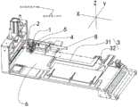
图1是根据本发明第一实施例的自封袋骨条压合装置的具体应用示意图;1 is a schematic diagram of a specific application of the self-sealing bag bone strip pressing device according to the first embodiment of the present invention;
图2是根据本发明第一实施例的自封袋骨条压合装置的立体示意图;2 is a schematic perspective view of the self-sealing bag bone strip pressing device according to the first embodiment of the present invention;
图3是根据本发明第一实施例的自封袋骨条压合装置的第一压合轮和第二压合轮的立体示意图;3 is a perspective view of the first pressing wheel and the second pressing wheel of the self-sealing bag bone strip pressing device according to the first embodiment of the present invention;
图4是根据本发明第一实施例的自封袋骨条压合装置的第一压合轮和第二压合轮的剖视示意图;4 is a schematic cross-sectional view of the first pressing wheel and the second pressing wheel of the self-sealing bag bone strip pressing device according to the first embodiment of the present invention;
图5是根据本发明第一实施例的自封袋骨条压合装置的第一压合轮和第二压合轮压合状态下的剖视示意图;5 is a schematic cross-sectional view of the first pressing wheel and the second pressing wheel of the self-sealing bag bone strip pressing device according to the first embodiment of the present invention in a pressing state;
图6是根据图5的A区域的放大示意图;Fig. 6 is according to the enlarged schematic diagram of the A area of Fig. 5;
图7是根据本发明第一实施例的自封袋骨条压合装置的压合槽与压合骨条的剖视示意图;7 is a schematic cross-sectional view of the pressing groove and the pressing bone of the self-sealing bag bone strip pressing device according to the first embodiment of the present invention;
图8是根据本发明第一实施例的自封袋骨条压合装置的上骨条和下骨条的结构示意图;8 is a schematic structural diagram of an upper bone strip and a lower bone strip of the self-sealing bag bone strip pressing device according to the first embodiment of the present invention;
图9是根据本发明第一实施例的自封袋骨条压合装置的定位组件的立体示意图;9 is a schematic perspective view of the positioning assembly of the self-sealing bag bone strip pressing device according to the first embodiment of the present invention;
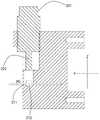
图10是根据本发明第一实施例的自封袋骨条压合装置的定位组件的剖视示意图;10 is a schematic cross-sectional view of the positioning assembly of the self-sealing bag bone strip pressing device according to the first embodiment of the present invention;
图11是根据本发明第一实施例的自封袋骨条压合装置的自封袋的结构示意图;FIG. 11 is a schematic structural diagram of a self-sealing bag of the self-sealing bag bone strip pressing device according to the first embodiment of the present invention;
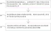
图12是根据本发明第一实施例的自封袋骨条压合装置的压合方法的流程示意图;12 is a schematic flow chart of a pressing method of the self-sealing bag bone strip pressing device according to the first embodiment of the present invention;
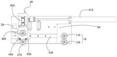
图13是根据本发明第二实施例的自封袋骨条压合装置的正视示意图。13 is a schematic front view of a self-sealing bag bone strip pressing device according to the second embodiment of the present invention.
标号清单:Label list:
1-压合组件;11-第一压合轮;111-第一滑槽;12-第二压合轮;121-第二滑槽;13-压合槽;14-缝隙1-pressing assembly; 11-first pressing wheel; 111-first chute; 12-second pressing wheel; 121-second chute; 13-pressing groove; 14-slot
2-定位组件;21-定位块;211-开口;212-通孔;22-固定件;221-固定气缸;222-固定杆;2-positioning assembly; 21-positioning block; 211-opening; 212-through hole; 22-fixing piece; 221-fixing cylinder; 222-fixing rod;
3-移袋组件;31-推送杆;32-推送气缸;3-push bag assembly; 31-push rod; 32-push cylinder;
4-调位组件;41-平移气缸;42-平移滑轨;43-平移滑块;45-升降气缸; 44-平移安装板;46A-第一调位轮;47A-第二调位轮;4-Positioning assembly; 41-Translation cylinder; 42-Translation slide rail; 43-Translation slider; 45-Lifting cylinder; 44-Translation mounting plate; 46A-First position adjustment wheel; 47A-Second position adjustment wheel;
7-自封袋;71-上骨条;711-凸起部;72-下骨条;721-凹槽部;73-底部封闭端;74-侧边封闭端;75-开口端;76-压合骨条;7- Self-sealing bag; 71- Upper bone strip; 711- Raised part; 72- Lower bone strip; 721- Groove part; 73- Bottom closed end; 74- Side closed end; 75- Open end; 76- Press joint strip;
5-安装板;6-输送轨道;8-入口;5-installation plate; 6-conveyor track; 8-inlet;
L1-上骨条在Y轴方向上的最大宽度;L1 - the maximum width of the upper bone strip in the Y-axis direction;
H1-上骨条在Z轴方向上的最大厚度;H1 - the maximum thickness of the upper bone strip in the Z-axis direction;
L2-下骨条在Y轴方向上的最大宽度;L2 - the maximum width of the lower bone strip in the Y-axis direction;
H2-下骨条在Z轴方向上的最大厚度;H2 - the maximum thickness of the lower bone strip in the Z-axis direction;
H3-压合骨条在Z轴方向上的最大厚度;H3 - the maximum thickness of the pressed bone strip in the Z-axis direction;
L4-压合槽在Y轴方向上的最大宽度;L4 - the maximum width of the pressing groove in the Y-axis direction;
H4-压合槽在Z轴方向上的最大高度;H4 - the maximum height of the press groove in the Z-axis direction;
H5-开口在Z轴方向上的高度;H5 - the height of the opening in the Z-axis direction;
H41-缝隙在Z轴方向上的高度。H41 - The height of the gap in the Z-axis direction.
具体实施方式Detailed ways
下面将结合本发明的实施例中附图,对本发明实施例中的技术方案进行清楚、完整地描述,显然,所描述的实施例仅仅是本发明一部分实施例,而不是全部的实施例。通常在此处附图中描述和示出的本发明实施例的组件可以以各种不同的配置来布置和设计。因此,以下对在附图中提供的本发明的实施例的详细描述并非旨在限制要求保护的本发明的范围,而是仅仅表示本发明的选定实施例。基于本发明的实施例,本领域技术人员在没有做出创造性劳动的前提下所获得的所有其他实施例,都属于本发明保护的范围。The technical solutions in the embodiments of the present invention will be clearly and completely described below with reference to the accompanying drawings in the embodiments of the present invention. Obviously, the described embodiments are only a part of the embodiments of the present invention, not all of the embodiments. The components of the embodiments of the invention generally described and illustrated in the drawings herein may be arranged and designed in a variety of different configurations. Thus, the following detailed description of the embodiments of the invention provided in the accompanying drawings is not intended to limit the scope of the invention as claimed, but is merely representative of selected embodiments of the invention. Based on the embodiments of the present invention, all other embodiments obtained by those skilled in the art without creative work fall within the protection scope of the present invention.
第一实施例first embodiment
首先,参照图1至图12对本发明的第一实施例涉及的自封袋骨条压合装置进行说明。First, with reference to FIGS. 1 to 12 , the self-sealing bag bone strip pressing device according to the first embodiment of the present invention will be described.
如图1所示,一种自封袋骨条压合装置,自封袋7的开口端75设置有用于封口的上骨条71和下骨条72,所述自封袋骨条压合装置用于在输送轨道 6上将自封袋7的上骨条71和下骨条72压合形成压合骨条76,所述自封袋骨条压合装置包括用于沿X轴方向移动自封袋7的移袋组件3,用于对压合骨条76进行定位的定位组件2,以及用于将上骨条71和下骨条72压合的压合组件1;所述压合组件1和定位组件2沿自封袋7移动方向依次设置于输送轨道6的一侧。所述自封袋骨条压合装置还包括用于安装所述压合组件1 和定位组件2的安装板5,所述安装板5位于输送轨道6的一侧。As shown in FIG. 1, a self-sealing bag bone strip pressing device, the
参阅图8和图11,自封袋7是通过压合可自动封口的包装袋,在本实施例中,所述自封袋7具有底部封闭端73、侧边封闭端74和开口端75。在本实施例中,自封袋7是一种连续的自封胶袋,是指用于自动化包装设备的预开口连卷胶袋或单边开口连卷塑料袋。所述的连续的自封胶袋在装入产品之后进行热封切断,形成单独的切离的自封胶袋。所述自封袋7的开口端75 设置有用于封口的上骨条71和下骨条72,所述上骨条71具有凸起部711,所述下骨条72具有凹槽部721,通过将上骨条71的凸起部711压合至下骨条72的凹槽部721中形成压合骨条76,完成对自封袋7的自动封口。8 and 11 , the self-sealing
参阅图1,在本实施例中,所述自封袋骨条压合装置应用于一种遥控器包装设备中。所述压合组件1的一侧设置有遥控器的入口8,该入口8位于压合组件1的上游。所述移袋组件3包括用于推送遥控器的推送杆31,以及用于驱动推送杆31的推送气缸32,所述移袋组件3将遥控器沿X轴方向推送至自封袋7的侧边封闭端74处后继续推送从而沿X轴方向移动自封袋7。可以理解的是,本实施例中的移袋组件3仅是一种优选方式,所述移袋组件 3还可以通过其他方式设置,例如:在自封袋7移动方向下游设置夹爪以及驱动夹爪沿X轴方向移动的气缸或电机,通过夹爪夹持自封袋7后通过气缸或电机带动夹爪沿X轴移动,从而带动自封袋7移动。所述移袋组件3的设置方式可以根据自封袋骨条压合装置的不同应用场景设置,能够实现上述作用的移袋组件3均可用于本发明,由此相应地可以对移袋组件3进行改进,也在本发明的保护范围内。Referring to FIG. 1 , in this embodiment, the self-sealing bag bone strip pressing device is used in a remote control packaging device. One side of the pressing assembly 1 is provided with an
如图3至图7所示,所述压合组件1包括第一压合轮11和第二压合轮 12,所述第一压合轮11上设置有第一滑槽111,所述第二压合轮12上设置有第二滑槽121,所述第一滑槽111和第二滑槽121配合形成用于将上骨条71和下骨条72压合的压合槽13。在本实施例中,所述第一压合轮11与升降气缸45相连接,所述第二压合轮12安装在平移安装板44上,所述升降气缸45和第一压合轮11位于第二压合轮12上方,所述第一压合轮11能够通过升降气缸45带动向第二压合轮12移动,所述第一压合轮11和第二压合轮12在贴近后所述第一滑槽111和第二滑槽121配合形成压合槽13,所述上骨条71和下骨条72位于所述压合槽13中。As shown in FIGS. 3 to 7 , the pressing assembly 1 includes a first
参阅图4和图5,所述第一滑槽111为截面呈V型的滑槽,第二滑槽121 为截面呈V型的滑槽,所述第一滑槽111和第二滑槽121配合形成压合槽13。压合槽13压合状态下在Z轴方向上的高度从对角向两侧逐渐减小,压合状态下在Y轴方向上的宽度从对角向两侧逐渐减小。其中,对角是指在Z轴方向上正对的两个对角以及在Y轴方向上正对的两个对角。4 and 5 , the
在本发明中,所述压合槽13的压合状态是指:当第一压合轮11和第二压合轮12相互靠近,第一滑槽111和第二滑槽121配合形成压合槽13,同时在压合槽13的两侧会形成有用于通过自封袋7的缝隙14,所述的压合状态是指当所述缝隙14的高度H41小于压合骨条76在Z轴方向上的厚度H3 且大于自封袋厚度时的一种状态。自封袋7常见的规格厚度一般为单面 0.03mm,又叫3丝,3s,也有0.03mm~0.2mm等,可以理解的是,自封袋7 可根据不同需要生产不同厚度,在此不做限制。In the present invention, the pressing state of the
由此,不同宽度、厚度的骨条压合槽13能够适用于不同宽度、厚度的骨条,同时骨条能够与第一滑槽111和第二滑槽121的各个侧边接触,在压合组件1对上骨条71和下骨条72进行压合时的施力点更多,压合效果更好。可以理解的是,所述第一滑槽111和第二滑槽121的截面形状还可以是梯形、半圆形等,本实施例中的V型只是表示一种优选的实施例,并不表示对本发明第一滑槽111和第二滑槽121的限制。Therefore, the bone
参阅图6至图8,所述压合槽13压合状态下在Y轴方向上的最大宽度 L4小于在Y轴方向上上骨条71宽度L1与下骨条72宽度L2之和,所述压合槽13压合状态下在Z轴方向上的最大高度H4小于在Z轴方向上上骨条71 厚度H1与下骨条72厚度H2之和。由此在移袋组件3沿X轴方向移动自封袋7时,上骨条71和下骨条72经过压合槽13后会自动压合。6 to 8, the maximum width L4 of the
如图9和图10所示,所述定位组件2包括定位块21,所述定位块21 中设置有用于穿设自封袋7的开口211和用于穿设压合骨条76的通孔212,所述开口211在Z轴方向上的高度H5小于压合骨条76在Z轴方向上的厚度 H3。As shown in FIG. 9 and FIG. 10 , the
具体来说,遥控器通过自封袋7的开口端75进入自封袋7中,然后通过移袋组件3将遥控器沿X轴方向推送。在移袋组件3对遥控器进行推送过程中,自封袋7会由于遥控器的进入产生形变,自封袋7中部会鼓起从而导致自封袋7整体向中间缩紧,同时在推送过程中可能会使得自封袋7偏移原来的移动方向。Specifically, the remote controller enters into the
因此,需要通过定位组件2对自封袋7进行定位,所述自封袋7在移动过程中,所述压合骨条76始终位于通孔212中。所述开口211在Z轴方向上的高度H5小于压合骨条76在Z轴方向上的厚度H3,使得压合骨条76不会由于自封袋7的形变或由于移袋组件3的推送导致脱离通孔212。由此,所述定位组件2通过定位块21对压合骨条76的位置进行定位以及限制,从而对自封袋7进行定位。Therefore, the
所述定位组件2还包括有用于固定压合骨条76的固定件22,所述固定件22包括固定气缸221和固定杆222,所述固定件22安装在定位块21中,所述固定杆222能够通过固定气缸221伸入所述通孔212中。所述固定件22 用于与下述调位组件4配合对自封袋7进行二次调位。The
如图2所示,所述自封袋骨条压合装置还包括用于调整压合骨条76位置的调位组件4,所述调位组件4包括平移气缸41、平移滑轨42、平移滑块43、平移安装板44和升降气缸45,所述平移滑块43套设在平移滑轨42上,所述平移安装板44与平移滑块43相连接,所述平移气缸41与平移安装板 44相连接,所述升降气缸45安装在平移安装板44上,所述第一压合轮11 与升降气缸45相连接,所述第二压合轮12安装在平移安装板44上。As shown in FIG. 2 , the self-sealing bag bone strip pressing device further includes a
所述定位组件2通过定位块21对压合骨条76的位置进行定位以及限制,从而对自封袋7进行定位,但是发明人发现在重复不断的包装过程中,自封袋7还是会产生偏移影响包装效果,特别是远离定位组件2的位于自封袋7 移动方向上游的自封袋7。因此,需要通过调位组件4对自封袋7进行二次调位,保证自封袋7的位置。The
所述调位组件4的具体调节方式:所述固定件22通过固定气缸221驱动固定杆222将压合骨条76固定,升降气缸45带动第一压合轮11向上移动,压合槽13张开,平移气缸41带动升降气缸45、第一压合轮11和第二压合轮12移动至定位组件2处,升降气缸45带动第一压合轮11向下移动,使得压合骨条76位于压合槽13中,然后平移气缸41带动升降气缸45、第一压合轮11和第二压合轮12反向移动至原位。The specific adjustment method of the positioning assembly 4: the fixing
所述调位组件4与压合组件1配合,通过压合槽13对压合骨条76的限位,使得平移气缸41带动升降气缸45、第一压合轮11和第二压合轮12反向移动至原位的过程中,将压合骨条76捋至原来的方向和位置上。同时在调位的过程中还能够对压合骨条76进行二次压合防止在移袋组件3对遥控器进行推送过程中导致压合骨条76张开。The
如图12所示,本发明还公开了一种自封袋7骨条压合方法,包括步骤:As shown in Figure 12, the present invention also discloses a method for pressing 7 bone strips of a self-sealing bag, comprising the steps:
S1:将自封袋7放置在输送轨道6上,自封袋7的开口端75位于靠近定位组件2和压合组件1的一侧,自封袋7的上骨条71和下骨条72穿设于定位组件2和压合组件1之中。具体来说,所述上骨条71和下骨条72穿过压合组件1的压合槽13,上骨条71和下骨条72在经过压合槽13后被压合形成压合骨条76,压合骨条76穿过所述定位组件2中的通孔212。S1: Place the
S2:通过移袋组件3沿X轴方向移动自封袋7,同时压合组件1将上骨条71和下骨条72压合形成压合骨条76。具体来说,所述上骨条71和下骨条72穿过压合组件1的压合槽13,所述压合槽13Y轴方向上的最大宽度L4 小于在Y轴方向上上骨条71的宽度L1与下骨条72的宽度L2之和,所述压合槽13Z轴方向上的最大高度H4小于在Z轴方向上上骨条71的厚度H1与下骨条72的厚度H2之和。由此在移袋组件3沿X轴方向移动自封袋7时,上骨条71和下骨条72经过压合槽13后会自动压合。S2 : Move the self-sealing
S3:通过固定件22将压合骨条76固定,然后通过调位组件4沿自封袋 7移动方向的反方向移动对压合骨条76的位置进行调整。所述调位组件4 与压合组件1配合,通过压合槽13对压合骨条76的限位,使得平移气缸41 带动升降气缸45、第一压合轮11和第二压合轮12反向移动至原位的过程中,将压合骨条76捋至原来的方向和位置上。同时在调位的过程中还能够对压合骨条76进行二次压合防止在移袋组件3对遥控器进行推送过程中导致压合骨条76张开。S3: Fix the
具体的,在步骤S2中,通过升降气缸45带动第一压合轮11向下移动,使得第一压合轮11上的第一滑槽111和第二压合轮12上的第二滑槽121配合形成压合槽13,上骨条71和下骨条72通过移袋组件3带动自封袋7移动过程中经过压合槽13形成压合骨条76。Specifically, in step S2 , the lifting
在步骤S3中,升降气缸45带动第一压合轮11向上移动,压合槽13张开,平移气缸41带动升降气缸45、第一压合轮11和第二压合轮12移动至定位组件2处,升降气缸45带动第一压合轮11向下移动,使得压合骨条76 位于压合槽13中,然后平移气缸41带动升降气缸45、第一压合轮11和第二压合轮12反向移动至原位。In step S3, the lifting
第二实施例Second Embodiment
接着,参照图13,对本发明的第二实施例涉及的自封袋骨条压合装置进行说明。此外,除非特别说明,第二实施例涉及的自封袋骨条压合装置的构成,与第一实施例中参照图1至图12说明的构成相同。以下,主要对第二实施例涉及的自封袋骨条压合装置的构成中与第一实施例不同的构成部分进行说明,对与第一实施例涉及的自封袋骨条压合装置相同的结构进行简略说明。Next, with reference to FIG. 13 , the self-sealing bag bone strip pressing device according to the second embodiment of the present invention will be described. In addition, unless otherwise specified, the structure of the self-sealing bag rib pressing device according to the second embodiment is the same as that described with reference to FIGS. 1 to 12 in the first embodiment. Hereinafter, the structure of the self-sealing bag bone strip press-fitting device according to the second embodiment will be mainly explained, and the components that are different from the first embodiment will be described, and the same structure as the self-sealing bag bone strip press-fitting device related to the first embodiment will be described. Brief description is given.
如图13所示,所述压合组件1A包括第一压合轮11A和第二压合轮12A,与第一实施例不同的是,所述第一压合轮11A和第二压合轮12A均固定安装在安装板5A上。As shown in FIG. 13 , the
所述调位组件4A位于定位组件2A和压合组件1A之间,所述调位组件 4A包括平移气缸41A、平移滑轨42A、平移滑块43A、平移安装板44A、升降气缸45A、第一调位轮46A和第二调位轮47A,所述平移滑块43A套设在平移滑轨42A上,所述平移安装板44A与平移滑块43A相连接,所述平移气缸 41A与平移安装板44A相连接,所述平移气缸41A用于带动平移安装板44A 在定位组件2A和压合组件1A之间来回移动,所述升降气缸45A安装在平移安装板44A上,所述第一调位轮46A与升降气缸45A相连接,所述第二调位轮47A安装在平移安装板44A上并位于第一调位轮46A和升降气缸45A的下方。The
所述第一调位轮46A和第二调位轮47A与第一压合轮11A和第二压合轮 12A的结构相同,本实施例的调位组件4A的调位方式与第一实施例大致相同,通过第一调位轮46A和第二调位轮47A对压合骨条76的限位来调整自封袋7的位置。与第一实施例不同的是,在第二实施例中调位组件4A始终在定位组件2A和压合组件1A之间来回运动,调位更加快捷,由此包装遥控器也更快。The
在本发明的描述中,需要理解的是,术语“第一”、“第二”等仅用于描述目的,而不能理解为指示或暗示相对重要性。对于本领域的普通技术人员而言,可以具体情况理解上述术语在本发明中的具体含义。此外,在本发明的描述中,除非另有说明,“多个”的含义是两个或两个以上。In the description of the present invention, it should be understood that the terms "first", "second" and the like are used for descriptive purposes only, and should not be construed as indicating or implying relative importance. For those of ordinary skill in the art, the specific meanings of the above terms in the present invention can be understood in specific situations. Also, in the description of the present invention, unless otherwise specified, "plurality" means two or more.
尽管已经示出和描述了本发明的实施例,本领域的普通技术人员可以理解:在不脱离本发明的原理和宗旨的情况下可以对这些实施例进行多种变化、修改、替换和变型,本发明的范围由权利要求及其等同物限定。Although embodiments of the present invention have been shown and described, it will be understood by those of ordinary skill in the art that various changes, modifications, substitutions and alterations can be made in these embodiments without departing from the principles and spirit of the invention, The scope of the invention is defined by the claims and their equivalents.
Claims (7)
Translated fromChineseApplications Claiming Priority (2)
| Application Number | Priority Date | Filing Date | Title |
|---|---|---|---|
| CN2019100824894 | 2019-01-28 | ||
| CN201910082489 | 2019-01-28 |
Publications (2)
| Publication Number | Publication Date |
|---|---|
| CN109969481A CN109969481A (en) | 2019-07-05 |
| CN109969481Btrue CN109969481B (en) | 2020-10-30 |
Family
ID=67080776
Family Applications (1)
| Application Number | Title | Priority Date | Filing Date |
|---|---|---|---|
| CN201910233211.2AExpired - Fee RelatedCN109969481B (en) | 2019-01-28 | 2019-03-26 | A kind of self-sealing bag bone strip pressing device and pressing method |
Country Status (1)
| Country | Link |
|---|---|
| CN (1) | CN109969481B (en) |
Families Citing this family (4)
| Publication number | Priority date | Publication date | Assignee | Title |
|---|---|---|---|---|
| IT202100002633A1 (en)* | 2021-02-05 | 2022-08-05 | Ica Spa | CLOSURE SYSTEM FOR PACKAGES WITH SNAP-IN RESEALABLE ELEMENT |
| CN113183531A (en)* | 2021-05-20 | 2021-07-30 | 郭朝华 | Intelligent device for automatic limiting and equidistant cutting of bone chains for bone chain bag processing |
| CN116374318A (en)* | 2022-12-23 | 2023-07-04 | 珠海精科智创科技有限公司 | Automatic bag opening and sealing device for self-sealing bags |
| CN116534323B (en)* | 2023-03-30 | 2025-08-22 | 恒林家居股份有限公司 | Seat cover installation method and equipment |
Family Cites Families (7)
| Publication number | Priority date | Publication date | Assignee | Title |
|---|---|---|---|---|
| CN204642295U (en)* | 2015-04-01 | 2015-09-16 | 东莞航科航空技术有限公司 | A self-sealing bag opening and sealing device |
| CN104828265B (en)* | 2015-04-21 | 2017-01-25 | 江苏比微曼智能科技有限公司 | Automatic packing machine |
| CN206562045U (en)* | 2017-02-23 | 2017-10-17 | 中山市太力家庭用品制造有限公司 | A kind of sealing clip sealed for vacuum bag |
| CN207292663U (en)* | 2017-05-09 | 2018-05-01 | 上海松川远亿机械设备有限公司 | A kind of clip chain pressuring flat device of self-styled bag package machine |
| CN206813424U (en)* | 2017-05-31 | 2017-12-29 | 天津市虎豹调味品酿造有限公司 | A kind of sterile packaging apparatus for soya sauce |
| CN207613303U (en)* | 2017-12-06 | 2018-07-17 | 尼克 | Pull head and its fastener assembly |
| CN108891679A (en)* | 2018-07-04 | 2018-11-27 | 合肥欧语自动化有限公司 | A kind of valve bag automation closing device |
- 2019
- 2019-03-26CNCN201910233211.2Apatent/CN109969481B/ennot_activeExpired - Fee Related
Also Published As
| Publication number | Publication date |
|---|---|
| CN109969481A (en) | 2019-07-05 |
Similar Documents
| Publication | Publication Date | Title |
|---|---|---|
| CN109969481B (en) | A kind of self-sealing bag bone strip pressing device and pressing method | |
| US4898280A (en) | Reclosable bag | |
| US4979933A (en) | Reclosable bag | |
| US4936817A (en) | Reclosable bag | |
| CA2403083C (en) | Zippered resealable closure | |
| CN111788067B (en) | Bag making machine and method for manufacturing plastic bag | |
| CN108439027A (en) | A kind of horizontally disposed formula paper tape doubling-up device | |
| CN208234248U (en) | A kind of horizontally disposed formula paper tape doubling-up device | |
| US10689142B2 (en) | Apparatus to form edges in a package made of flexible material | |
| CN109334110B (en) | Inward folding device for both sides of plastic three-dimensional bag sheets | |
| JPH1073369A (en) | Iron plate bending apparatus and method for outer box of refrigerator | |
| CN109895451B (en) | Box paper forming device in special-shaped box for cigarettes | |
| EP0330069A2 (en) | Device to frame photographic films | |
| CN115231055B (en) | Continuous automatic bagging machine with bag self-adhesion bag and zipper bag entering function | |
| CN210083741U (en) | A remote control product automatic packaging equipment | |
| CN100436263C (en) | Sealing device and method for sealing a package | |
| CN217348479U (en) | A carton back sealing system | |
| CN117021230A (en) | Method and tooling equipment for efficiently machining plastic gate | |
| CN216316012U (en) | File pocket zip fastener pull head installation device | |
| CN105014385A (en) | Cutting device of strip-shaped workpiece with C-shaped cross section and bending mold | |
| CN111792073B (en) | Packing carton tongue insertion mechanism and seal assembly line | |
| CN108792048B (en) | Automatic bag opening device and method of vacuum chuck | |
| CN212768495U (en) | Multi-station synchronous conveying device | |
| JP2009096502A (en) | Envelope flap bending apparatus and sealing system having the same | |
| CN2839134Y (en) | Sealing clamp for plastic bag |
Legal Events
| Date | Code | Title | Description |
|---|---|---|---|
| PB01 | Publication | ||
| PB01 | Publication | ||
| SE01 | Entry into force of request for substantive examination | ||
| SE01 | Entry into force of request for substantive examination | ||
| GR01 | Patent grant | ||
| GR01 | Patent grant | ||
| CF01 | Termination of patent right due to non-payment of annual fee | Granted publication date:20201030 | |
| CF01 | Termination of patent right due to non-payment of annual fee |