CN109932563B - A smart energy meter with automatic reporting of power failure - Google Patents
A smart energy meter with automatic reporting of power failureDownload PDFInfo
- Publication number
- CN109932563B CN109932563BCN201910093516.8ACN201910093516ACN109932563BCN 109932563 BCN109932563 BCN 109932563BCN 201910093516 ACN201910093516 ACN 201910093516ACN 109932563 BCN109932563 BCN 109932563B
- Authority
- CN
- China
- Prior art keywords
- power supply
- static contact
- energy meter
- resistor
- unit
- Prior art date
- Legal status (The legal status is an assumption and is not a legal conclusion. Google has not performed a legal analysis and makes no representation as to the accuracy of the status listed.)
- Active
Links
Images


Landscapes
- Arrangements For Transmission Of Measured Signals (AREA)
- Direct Current Feeding And Distribution (AREA)
Abstract
Translated fromChinese
Description
Translated fromChinese技术领域technical field
本发明涉及智能电能表技术领域,具体涉及一种掉电自动上报的智能电能表。The invention relates to the technical field of smart electric energy meters, in particular to an intelligent electric energy meter that automatically reports power failure.
背景技术Background technique
电网的建设使得天气、供电量不足以及线路过载造成的停电事故得到了有效的解决。然而电网中使用大量的智能设备,智能设备通常具有丰富复杂的功能。其发生故障的概率较大,且故障类型多样化。导致了电网随机故障引起部分区域停电故障的概率增大。这种停电故障通常发生在设备和线路比较复杂的配电网。其影响范围虽然通常较小,但故障的排查难度大。经常需要沿着配网线路,逐个排查配网中的可能发生故障的设备。配网线路走势复杂,排查难度大,故障恢复时间长。严重影响了用户生活和用电需求。因而急需研制出一种能够快速定位故障区域的方案,为配网故障排查提供指导,加快配网故障恢复效率。The construction of the power grid has effectively solved the blackout accidents caused by the weather, insufficient power supply and overloaded lines. However, a large number of smart devices are used in the power grid, and smart devices usually have rich and complex functions. The probability of failure is high, and the types of failures are diverse. As a result, the probability of power failure in some areas caused by random faults in the power grid increases. This kind of power failure usually occurs in the distribution network with complex equipment and lines. Although the scope of its influence is usually small, it is difficult to troubleshoot the fault. It is often necessary to check the possible faulty devices in the distribution network one by one along the distribution network line. The trend of distribution network lines is complex, the troubleshooting is difficult, and the fault recovery time is long. Seriously affect the user's life and electricity demand. Therefore, it is urgent to develop a solution that can quickly locate fault areas, provide guidance for distribution network troubleshooting, and speed up distribution network fault recovery efficiency.
中国专利CN108020809A,公开日2018年5月11日,CN108020809A 一种具有停电检测及告警功能的通信模块及停电检测告警方法,具有停电检测及告警功能的通信模块,包括:MCU;与MCU相连的弱电接口检测电路,弱电接口检测电路的输入端与电能表弱电接口相连,采集电能表弱电接口电源端的电压值;与MCU相连的强电接口检测电路,强电接口检测电路的输入端与电能表强电接口相连;与MCU相连的通信电路,通信电路与天线相连;与MCU相连的DC-DC电路,DC-DC电路的输入端与电能表弱电接口的电源端相连,并为MCU、通信电路及下述法拉电容电路供电;法拉电容电路,法拉电容电路分别与DC-DC电路、MCU及通信电路相连。其可为电能表实现停电检测和停电告警功能,为电力企业提供故障信息。但其需要额外设备的安装,安装工作量大,且该额外设备需要单独供电,其电池的更换是一项十分繁重的工作。Chinese patent CN108020809A, published on May 11, 2018, CN108020809A A communication module with power failure detection and alarm functions and a power failure detection and alarm method, a communication module with power failure detection and alarm functions, including: MCU; Interface detection circuit, the input terminal of the weak current interface detection circuit is connected with the weak current interface of the electric energy meter, and the voltage value of the power supply terminal of the weak current interface of the electric energy meter is collected; The electrical interface is connected; the communication circuit connected to the MCU, the communication circuit is connected to the antenna; the DC-DC circuit connected to the MCU, the input end of the DC-DC circuit is connected to the power supply end of the weak current interface of the electric energy meter, and is the MCU, communication circuit and The following farad capacitor circuit is powered; the farad capacitor circuit and the farad capacitor circuit are respectively connected with the DC-DC circuit, the MCU and the communication circuit. It can realize power failure detection and power failure alarm functions for electric energy meters, and provide fault information for power companies. However, it requires the installation of additional equipment, the installation workload is large, and the additional equipment needs to be powered independently, and the replacement of the battery is a very heavy task.
发明内容SUMMARY OF THE INVENTION
本发明要解决的技术问题是:目前缺乏能够在配网停电故障时自动告警的装置或装置部署工作过于繁琐的技术问题。提出了一种方便部署的能够停电告警的掉电自动上报的智能电能表。The technical problem to be solved by the present invention is that there is currently a lack of a device capable of automatically alarming when a power failure occurs in the distribution network, or the technical problem that the deployment of the device is too cumbersome. A smart electric energy meter that is easy to deploy and can automatically report power failures with power failure alarms is proposed.
为解决上述技术问题,本发明所采取的技术方案为:一种掉电自动上报的智能电能表,包括供电电路、超级电容、应急通信模块和服务器,所述供电电路、超级电容以及应急通信模块均安装在智能电能表的表壳内,所述供电电路包括整流单元、应急供电单元和稳压单元,所述整流单元输入端与入户线连接,整流单元输出端与稳压单元输入端连接,所述稳压单元输出端与应急供电单元输入端以及智能电能表供电端子连接,所述应急供电单元包括可控开关,所述可控开关控制端与稳压单元输出端连接,所述超级电容与应急供电单元连接,所述可控开关连接在应急供电单元与应急通信模块之间,智能电能表掉电时所述稳压单元输出端电压降低并使所述可控开关导通,所述应急通信模块由应急供电单元供电,所述应急通信模块与服务器建立通信连接,并将至少包括智能电能表位置信息的报文发送到服务器。当入户线故障停电时,供电电路会启用超级电容为应急通信模块供电,通过应急通信模块将至少包括故障地理位置的信息发送到服务器,为故障排查提供参考。In order to solve the above-mentioned technical problems, the technical solution adopted by the present invention is: a smart electric energy meter that automatically reports power failure, including a power supply circuit, a super capacitor, an emergency communication module and a server, the power supply circuit, the super capacitor and the emergency communication module. They are all installed in the watch case of the smart energy meter. The power supply circuit includes a rectifier unit, an emergency power supply unit and a voltage stabilizer unit. The input end of the rectifier unit is connected to the household line, and the output end of the rectifier unit is connected to the input end of the voltage stabilizer unit. The output end of the voltage stabilization unit is connected to the input end of the emergency power supply unit and the power supply terminal of the smart energy meter, the emergency power supply unit includes a controllable switch, and the control end of the controllable switch is connected to the output end of the voltage stabilization unit, and the super The capacitor is connected to the emergency power supply unit, and the controllable switch is connected between the emergency power supply unit and the emergency communication module. When the smart energy meter is powered off, the voltage of the output terminal of the voltage stabilization unit decreases and the controllable switch is turned on, so The emergency communication module is powered by an emergency power supply unit, the emergency communication module establishes a communication connection with the server, and sends a message including at least the location information of the smart electric energy meter to the server. When the household line fails and the power goes out, the power supply circuit will enable the super capacitor to supply power to the emergency communication module, and send at least the information including the fault location to the server through the emergency communication module to provide a reference for troubleshooting.
作为优选,所述供电电路包括变压器、整流桥T1、电阻R1、电阻R2、电阻R3、电阻R4、电容C1、电容C3、二极管D1、二极管D2、二极管D3、P-MOS管M1、P-MOS管M2、压电陶瓷PE、电极板B1、电极板B2、静触头P1、动触头P2、无源三端稳压管U1和开关K1,整流桥T1输入端经过所述变压器分别与入户火线以及入户零线连接,整流桥T1输出端正极与二极管D1阳极以及电阻R1第一端连接,整流桥T1输出端负极接地,二极管D1阴极与二极管D2阳极以及电容C1第一端连接,二极管D2阴极与P-MOS管M1漏极、二极管D3阳极以及无源三端稳压管U1输入端连接,二极管D3阴极与P-MOS管M1源极、P-MOS管M2源极以及超级电容C2第一端连接,电阻R1第二端、电容C1第二端以及电容C2第二端均接地,P-MOS管M2漏极与应急通信模块U2的供电正极连接,应急通信模块U2的供电负极接地,无源三端稳压管U1输出端与开关K1、电阻R3第二端、电阻R4第一端以及OUT+端连接,开关K1第二端与P-MOS管M1栅极、P-MOS管M2栅极、电阻R3第一端、电容C3第一端、电极板B1以及静触头P1连接,动触头P2与电阻R2第一端连接,电容C3第二端、电阻R2第二端、电阻R4第二端、电极板B2以及OUT-端均接地,OUT+端以及OUT-端为智能电能表供电,电极板B1与电极板B2相对平行固定安装在智能电能表的表壳内,压电陶瓷PE安装在电极板B1与电极板B2之间,压电陶瓷PE靠近电极板B2的端为固定端,压电陶瓷PE靠近电极板B1的端为悬空端,动触头P2与压电陶瓷PE的悬空端固定连接,压电陶瓷PE极化方向为当电极板B1相对电极板B2的电压为正且升高时,压电陶瓷PE收缩使悬空端向固定端运动。Preferably, the power supply circuit includes a transformer, a rectifier bridge T1, a resistor R1, a resistor R2, a resistor R3, a resistor R4, a capacitor C1, a capacitor C3, a diode D1, a diode D2, a diode D3, a P-MOS transistor M1, a P-MOS transistor Tube M2, piezoelectric ceramic PE, electrode plate B1, electrode plate B2, static contact P1, moving contact P2, passive three-terminal voltage regulator tube U1 and switch K1, the input end of the rectifier bridge T1 is connected to the input through the transformer respectively. The household live line and the household neutral line are connected, the positive pole of the output terminal of the rectifier bridge T1 is connected to the anode of the diode D1 and the first terminal of the resistor R1, the negative pole of the output terminal of the rectifier bridge T1 is connected to the ground, and the cathode of the diode D1 is connected to the anode of the diode D2 and the first terminal of the capacitor C1. The cathode of the diode D2 is connected to the drain of the P-MOS tube M1, the anode of the diode D3 and the input end of the passive three-terminal voltage regulator tube U1, the cathode of the diode D3 is connected to the source of the P-MOS tube M1, the source of the P-MOS tube M2 and the super capacitor The first end of C2 is connected, the second end of the resistor R1, the second end of the capacitor C1 and the second end of the capacitor C2 are all grounded, the drain of the P-MOS transistor M2 is connected to the positive electrode of the power supply of the emergency communication module U2, and the negative electrode of the power supply of the emergency communication module U2 Ground, the output end of the passive triode voltage regulator U1 is connected to the switch K1, the second end of the resistor R3, the first end of the resistor R4 and the OUT+ end, the second end of the switch K1 is connected to the gate of the P-MOS tube M1, the P-MOS tube The gate of M2, the first end of the resistor R3, the first end of the capacitor C3, the electrode plate B1 and the static contact P1 are connected, the moving contact P2 is connected with the first end of the resistor R2, the second end of the capacitor C3, the second end of the resistor R2, The second end of the resistor R4, the electrode plate B2 and the OUT- end are all grounded, and the OUT+ end and the OUT- end supply power to the smart energy meter. The ceramic PE is installed between the electrode plate B1 and the electrode plate B2. The end of the piezoelectric ceramic PE close to the electrode plate B2 is the fixed end, the end of the piezoelectric ceramic PE close to the electrode plate B1 is the floating end, and the movable contact P2 is connected to the piezoelectric ceramic. The suspended end of PE is fixedly connected, and the polarization direction of the piezoelectric ceramic PE is that when the voltage of the electrode plate B1 relative to the electrode plate B2 is positive and increases, the piezoelectric ceramic PE shrinks to move the suspended end to the fixed end.
供电电路的工作方法为:当入户线正常供电时,电容C1提供滤波,超级电容C2充电,无源三端稳压管U1将整流桥T1整流后的直流电转化为电压稳定的直流电,为智能电能表正常工作供电,电容C3充满电,电极板B1、B2之间存在电场,使压电陶瓷PE收缩,动触头P2与静触头P2脱离接触;当入户线故障停电时,电容C1内的电量逐渐被消耗,直到无源三端稳压管U1输出端的输出电压下降,电阻R4阻值较大,基本无电流通过,电容C3通过电阻R3以及OUT+端部分放电,导致电极板B1、B2之间电场强度降低,压电陶瓷PE伸长使动触头P2与静触头P1接触,电容C3通过电阻R2快速放电,使得P-MOS管M1、P-MOS管M2栅极电压足够低而均导通,超级电容C2通过P-MOS管M2为应急通信模块U2供电,应急通信模块U2集成有稳压元件或者外接稳压元件,稳压处理是本领域常规和惯用技术手段,在此不在详述,应急通信模块U2上电复位,即执行预置的通信程序,将至少包括智能电能表地理位置的报文,广播发送到服务器,超级电容C2通过P-MOS管M1为无源三端稳压管U1供电,维持智能电表短暂的继续工作。可选的,通过应急通信模块U2发出信号给智能电能表控制芯片,使智能电能表控制芯片执行数据保护的操作,芯片之间的相互通信是基本技术手段,在此不做详述。The working method of the power supply circuit is as follows: when the household line is normally supplied with power, the capacitor C1 provides filtering, the super capacitor C2 charges, and the passive three-terminal voltage regulator tube U1 converts the DC power rectified by the rectifier bridge T1 into a voltage-stable DC power. The electric energy meter works normally, the capacitor C3 is fully charged, and there is an electric field between the electrode plates B1 and B2, which causes the piezoelectric ceramic PE to shrink, and the moving contact P2 and the static contact P2 are out of contact; when the household line fails and the power goes out, the capacitor C1 The power inside is gradually consumed until the output voltage of the output terminal of the passive three-terminal Zener tube U1 drops, the resistance value of the resistor R4 is large, and basically no current passes through, and the capacitor C3 is partially discharged through the resistor R3 and the OUT+ terminal, resulting in the electrode plate B1, The electric field strength between B2 decreases, the piezoelectric ceramic PE stretches to make the moving contact P2 contact with the static contact P1, and the capacitor C3 discharges rapidly through the resistor R2, so that the gate voltage of the P-MOS transistor M1 and the P-MOS transistor M2 is sufficiently low And both are turned on, the super capacitor C2 supplies power to the emergency communication module U2 through the P-MOS tube M2, and the emergency communication module U2 is integrated with a voltage stabilizing element or an external voltage stabilizing element. Without going into details, the emergency communication module U2 is powered on and reset, that is, executes the preset communication program, and broadcasts at least the message including the geographic location of the smart energy meter to the server. The super capacitor C2 is a passive three through the P-MOS tube M1. The terminal voltage regulator tube U1 supplies power, and the smart meter continues to work for a short time. Optionally, the emergency communication module U2 sends a signal to the smart power meter control chip, so that the smart power meter control chip performs data protection operations.
开关K1的使用方法为:当智能电能表部署时,将开关K1闭合,待接线完成,智能电能表上电,无源三端稳压管U1几乎瞬间输出稳定直流电压,电容C3通过开关K1瞬间充满电,电阻R2上短暂的有电流通过,而后电极板B1、B2之间产生电场,压电陶瓷PE收缩,使动触头P2与静触头P1脱离接触,电阻R2上无电流通过,而后将开关K1断开;当入户线故障掉电时,电容C3电压降低后,动触头P2与静触头P1接触,电容C3通过电阻R2迅速放电,使电容C3的电压低于无源三端稳压管U1下降后的输出电压,但由于电阻R3的存在,使电容C3能够保持低于无源三端稳压管U1的输出电压,当无源三端稳压管U1由超级电容C2供电时,电阻R3的阻值较大,电阻R2的阻值较小,电容C3两端电压是无源三端稳压管U1输出电压在电阻R2、电阻R3构成串联通路上电阻R2的分压,该分压较低,不足以使压电陶瓷PE产生足够的形变使动触头P2与静触头P1脱离接触,因而当超级电容C2为无源三端稳压管U1供电时,P-MOS管M1以及P-MOS管M2能够保持导通;当故障修复后,需要用户手动短暂按压开关K1使之短暂闭合即可。The usage of switch K1 is as follows: when the smart energy meter is deployed, close the switch K1, and after the wiring is completed, the smart energy meter is powered on, the passive three-terminal voltage regulator U1 outputs a stable DC voltage almost instantaneously, and the capacitor C3 passes through the switch K1 instantaneously. When fully charged, there is a short-term current passing through the resistor R2, and an electric field is generated between the rear electrode plates B1 and B2, and the piezoelectric ceramic PE shrinks, so that the moving contact P2 is out of contact with the static contact P1, and there is no current passing through the resistor R2, and then Turn off the switch K1; when the household line fails and the power is turned off, after the voltage of the capacitor C3 decreases, the moving contact P2 contacts the static contact P1, and the capacitor C3 discharges rapidly through the resistor R2, so that the voltage of the capacitor C3 is lower than that of the passive three. The output voltage of the terminal regulator U1 after the drop, but due to the existence of the resistor R3, the capacitor C3 can keep the output voltage lower than the passive three-terminal regulator U1. When the passive three-terminal regulator U1 is replaced by the super capacitor C2 When supplying power, the resistance value of resistor R3 is relatively large, and the resistance value of resistor R2 is relatively small. The voltage across capacitor C3 is the voltage divided by the output voltage of passive three-terminal Zener tube U1. Resistor R2 and resistor R3 form the voltage division of resistor R2 on the series path. , the partial pressure is low, which is not enough to make the piezoelectric ceramic PE produce enough deformation to make the moving contact P2 and the static contact P1 out of contact, so when the super capacitor C2 supplies power to the passive three-terminal voltage regulator tube U1, P- The MOS tube M1 and the P-MOS tube M2 can be kept on; after the fault is repaired, the user needs to manually briefly press the switch K1 to make it closed briefly.
作为优选,所述应急通信模块包括ZigBee通信单元和存储器,所述ZigBee通信单元与服务器建立无线通信,所述存储器存储有智能电能表的地理位置信息,所述ZigBee通信单元上电复位后,将存储器内存储的信息发送到服务器。ZigBee能够建立距离较远的无线通信,从而能够在一个台区步骤若干个ZigBee基站即可形成较为可靠的无线连接。Preferably, the emergency communication module includes a ZigBee communication unit and a memory, the ZigBee communication unit establishes wireless communication with the server, the memory stores the geographic location information of the smart energy meter, and after the ZigBee communication unit is powered on and reset, the The information stored in the memory is sent to the server. ZigBee can establish long-distance wireless communication, so that several ZigBee base stations can form a relatively reliable wireless connection in one station area.
作为优选,还包括静触头调整座,所述静触头调整座包括基座、滑块和调节螺钉,所述基座与智能电能表表壳固定连接,所述滑块一端面与基座卡接,沿所述滑块与基座卡接方向加工有贯穿所述滑块的螺纹孔,基座上加工有与所述螺纹孔同心的通孔,所述调节螺钉与所述通孔铰接且沿轴线方向相对基座基本固定,所述调节螺钉与所述螺纹孔配合使滑块连接到基座上,所述静触头P1固定安装在所述滑块上。静触头调整座的使用方法为:将开关K1闭合,拧动调节螺钉,使静触头P1与动触头P2脱离接触,智能电能表在厂房内接通市电,此时动触头P2由压电陶瓷PE带动,向后退让一小段距离,拧动调节螺钉,使静触头P1足够靠近动触头P2,而后固定调节螺钉,在动触头P2以及静触头P1之间放置绝缘防摩擦垫片,将智能电能表从市电上切出,即可将智能电能表出厂,智能电能表部署时,需要将绝缘防摩擦垫片取出。Preferably, it also includes a static contact adjustment seat, the static contact adjustment seat includes a base, a slider and an adjustment screw, the base is fixedly connected to the smart energy meter case, and one end surface of the slider is connected to the base Clamping, along the clamping direction of the slider and the base, a threaded hole passing through the slider is machined, a through hole concentric with the threaded hole is machined on the base, and the adjusting screw is hinged with the through hole And it is basically fixed relative to the base along the axis direction, the adjusting screw cooperates with the threaded hole to connect the slider to the base, and the static contact P1 is fixedly installed on the slider. The use method of the static contact adjustment seat is: close the switch K1, turn the adjusting screw, make the static contact P1 and the moving contact P2 out of contact, and the smart energy meter is connected to the mains in the workshop, and the moving contact P2 is at this time. Driven by the piezoelectric ceramic PE, move back a short distance, turn the adjusting screw to make the static contact P1 close enough to the moving contact P2, then fix the adjusting screw, and place insulation between the moving contact P2 and the static contact P1 Anti-friction gasket, cut out the smart energy meter from the mains, then the smart energy meter can be shipped from the factory. When the smart energy meter is deployed, the insulating anti-friction gasket needs to be taken out.
作为优选,所述静触头P1以及动触头P2的接触部均呈平顶半球形,所述平顶半球形弧度顶部呈平顶状,所述平顶与半球形通过圆角过渡,所述静触头P1以及动触头P2的接触面均存在镀银层。平顶半球形以及圆角能够避免动触头P2与静触头P1之间存在较多灰尘积累,避免接触不良。Preferably, the contact parts of the static contact P1 and the moving contact P2 are both flat-topped hemispherical, the flat-topped hemispherical arc top is flat-topped, and the flat top and the hemisphere are transitioned through rounded corners, so The contact surfaces of the static contact P1 and the moving contact P2 both have a silver-plated layer. The flat-top hemispherical shape and the rounded corners can prevent a lot of dust accumulation between the moving contact P2 and the static contact P1 and avoid poor contact.
作为优选,还包括支持板,所述支持板位于静触头P1一侧,所述静触头P1通过第一胶体与所述滑块固定连接,所述静触头P1由所述静触头调整座调整完成后,通过第二胶体将静触头P1与支持板固定连接,并去除所述第一胶体。静触头P1固定后,即可将静触头调整座拆出,这样仅需要工厂内配备若干个静触头调整座即可,不需要为每个智能电能表均配置一个静触头调整座,节省成本。Preferably, it also includes a support plate, the support plate is located on the side of the static contact P1, the static contact P1 is fixedly connected to the slider through the first colloid, and the static contact P1 is formed by the static contact After the adjustment of the adjustment seat is completed, the static contact P1 is fixedly connected to the support plate through the second colloid, and the first colloid is removed. After the static contact P1 is fixed, the static contact adjustment seat can be removed, so that only several static contact adjustment seats are required in the factory, and there is no need to configure a static contact adjustment seat for each smart energy meter ,cut costs.
本发明的实质性效果是:当入户线故障停电时,供电电路会启用超级电容为应急通信模块供电,通过应急通信模块将至少包括故障地理位置的信息发送到服务器,为故障排查提供参考,加快检修进度,减小用户停电时长。The substantive effect of the present invention is: when the household line fails and the power goes out, the power supply circuit will enable the super capacitor to supply power to the emergency communication module, and the information including at least the geographical location of the fault will be sent to the server through the emergency communication module, so as to provide a reference for troubleshooting, Speed up maintenance progress and reduce the duration of user power outages.
附图说明Description of drawings
图1为实施例一掉电自动上报的智能电能表的功能模块连接示意图。FIG. 1 is a schematic diagram of connection of functional modules of a smart energy meter automatically reporting power failure according to Embodiment 1. As shown in FIG.
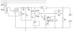
图2为实施例一供电电路的原理图。FIG. 2 is a schematic diagram of a power supply circuit according to the first embodiment.
图3为实施例二静触头调整座结构示意图。FIG. 3 is a schematic structural diagram of a static contact adjusting seat according to the second embodiment.
其中:1、基座,2、滑块,3、调节螺钉,100、入户线,100a、入户火线,100b、入户零线,200、供电电路,300、智能电能表供电端子,400、服务器。Among them: 1. Base, 2. Slider, 3. Adjusting screw, 100, Household wire, 100a, Household live wire, 100b, Household neutral wire, 200, Power supply circuit, 300, Smart energy meter power supply terminal, 400 ,server.
具体实施方式Detailed ways
下面通过具体实施例,并结合附图,对本发明的具体实施方式作进一步具体说明。The specific embodiments of the present invention will be further described in detail below through specific embodiments and in conjunction with the accompanying drawings.
实施例一:Example 1:
一种掉电自动上报的智能电能表,如图1所示,为实施例一掉电自动上报的智能电能表的功能模块连接示意图,本实施例包括供电电路200、超级电容、应急通信模块和服务器400,供电电路200、超级电容以及应急通信模块均安装在智能电能表的表壳内,供电电路200包括整流单元、应急供电单元和稳压单元,整流单元输入端与入户线100连接,整流单元输出端与稳压单元输入端连接,稳压单元输出端与应急供电单元输入端以及智能电能表供电端子300连接,应急供电单元包括可控开关,可控开关控制端与稳压单元输出端连接,超级电容与应急供电单元连接,可控开关连接在应急供电单元与应急通信模块之间,智能电能表掉电时稳压单元输出端电压降低并使可控开关导通,应急通信模块由应急供电单元供电,应急通信模块与服务器400建立通信连接,并将至少包括智能电能表位置信息的报文发送到服务器400。当入户线100故障停电时,供电电路200会启用超级电容为应急通信模块供电,通过应急通信模块将至少包括故障地理位置的信息发送到服务器400,为故障排查提供参考。A smart energy meter that automatically reports power failure, as shown in FIG. 1 , is a schematic diagram of the connection of functional modules of the smart energy meter that automatically reports power failure in Embodiment 1. This embodiment includes a
如图2所示,为实施例一供电电路的原理图,供电电路200包括变压器、整流桥T1、电阻R1、电阻R2、电阻R3、电阻R4、电容C1、电容C3、二极管D1、二极管D2、二极管D3、P-MOS管M1、P-MOS管M2、压电陶瓷PE、电极板B1、电极板B2、静触头P1、动触头P2、无源三端稳压管U1和开关K1,整流桥T1输入端经过变压器分别与入户火线100a以及入户零线100b连接,整流桥T1输出端正极与二极管D1阳极以及电阻R1第一端连接,整流桥T1输出端负极接地,二极管D1阴极与二极管D2阳极以及电容C1第一端连接,二极管D2阴极与P-MOS管M1漏极、二极管D3阳极以及无源三端稳压管U1输入端连接,二极管D3阴极与P-MOS管M1源极、P-MOS管M2源极以及超级电容C2第一端连接,电阻R1第二端、电容C1第二端以及电容C2第二端均接地,P-MOS管M2漏极与应急通信模块U2的供电正极连接,应急通信模块U2的供电负极接地,无源三端稳压管U1输出端与开关K1、电阻R3第二端、电阻R4第一端以及OUT+端连接,开关K1第二端与P-MOS管M1栅极、P-MOS管M2栅极、电阻R3第一端、电容C3第一端、电极板B1以及静触头P1连接,动触头P2与电阻R2第一端连接,电容C3第二端、电阻R2第二端、电阻R4第二端、电极板B2以及OUT-端均接地,OUT+端以及OUT-端为智能电能表供电,电极板B1与电极板B2相对平行固定安装在智能电能表的表壳内,压电陶瓷PE安装在电极板B1与电极板B2之间,压电陶瓷PE靠近电极板B2的端为固定端,压电陶瓷PE靠近电极板B1的端为悬空端,动触头P2与压电陶瓷PE的悬空端固定连接,压电陶瓷PE极化方向为当电极板B1相对电极板B2的电压为正且升高时,压电陶瓷PE收缩使悬空端向固定端运动。As shown in FIG. 2 , which is a schematic diagram of a power supply circuit in Embodiment 1, the
供电电路200的工作方法为:当入户线100正常供电时,电容C1提供滤波,超级电容C2充电,无源三端稳压管U1将整流桥T1整流后的直流电转化为电压稳定的直流电,为智能电能表正常工作供电,电容C3充满电,电极板B1、B2之间存在电场,使压电陶瓷PE收缩,动触头P2与静触头P2脱离接触;当入户线100故障停电时,电容C1内的电量逐渐被消耗,直到无源三端稳压管U1输出端的输出电压下降,电阻R4阻值较大,基本无电流通过,电容C3通过电阻R3以及OUT+端部分放电,导致电极板B1、B2之间电场强度降低,压电陶瓷PE伸长使动触头P2与静触头P1接触,电容C3通过电阻R2快速放电,使得P-MOS管M1、P-MOS管M2栅极电压足够低而均导通,超级电容C2通过P-MOS管M2为应急通信模块U2供电,应急通信模块U2集成有稳压元件或者外接稳压元件,稳压处理是本领域常规和惯用技术手段,在此不在详述,应急通信模块U2上电复位,即执行预置的通信程序,将至少包括智能电能表地理位置的报文,广播发送到服务器400,超级电容C2通过P-MOS管M1为无源三端稳压管U1供电,维持智能电表短暂的继续工作。可选的,通过应急通信模块U2发出信号给智能电能表控制芯片,使智能电能表控制芯片执行数据保护的操作,芯片之间的相互通信是基本技术手段,在此不做详述。The working method of the power supply circuit 200 is as follows: when the household line 100 is normally supplied with power, the capacitor C1 provides filtering, the super capacitor C2 is charged, and the passive three-terminal voltage regulator tube U1 converts the direct current rectified by the rectifier bridge T1 into direct current with stable voltage, Power supply for the normal operation of the smart energy meter, the capacitor C3 is fully charged, and there is an electric field between the electrode plates B1 and B2, which causes the piezoelectric ceramic PE to shrink, and the moving contact P2 and the static contact P2 are out of contact; when the household line 100 fails to power , the power in the capacitor C1 is gradually consumed until the output voltage of the output terminal of the passive three-terminal Zener tube U1 drops, the resistance of the resistor R4 is large, and basically no current passes through, and the capacitor C3 is partially discharged through the resistor R3 and the OUT+ terminal, causing the electrode The electric field strength between the plates B1 and B2 is reduced, the piezoelectric ceramic PE stretches so that the moving contact P2 is in contact with the static contact P1, and the capacitor C3 is rapidly discharged through the resistor R2, making the gates of the P-MOS transistors M1 and P-MOS transistors M2. The voltage is low enough to be turned on. The supercapacitor C2 supplies power to the emergency communication module U2 through the P-MOS tube M2. The emergency communication module U2 is integrated with a voltage stabilizing element or an external voltage stabilizing element. The voltage stabilization treatment is a conventional and customary technical means in the field , which will not be described in detail here, the emergency communication module U2 is powered on and reset, that is, executes the preset communication program, and broadcasts at least a message including the geographic location of the smart energy meter to the
开关K1的使用方法为:当智能电能表部署时,将开关K1闭合,待接线完成,智能电能表上电,无源三端稳压管U1几乎瞬间输出稳定直流电压,电容C3通过开关K1瞬间充满电,电阻R2上短暂的有电流通过,而后电极板B1、B2之间产生电场,压电陶瓷PE收缩,使动触头P2与静触头P1脱离接触,电阻R2上无电流通过,而后将开关K1断开;当入户线100故障掉电时,电容C3电压降低后,动触头P2与静触头P1接触,电容C3通过电阻R2迅速放电,使电容C3的电压低于无源三端稳压管U1下降后的输出电压,但由于电阻R3的存在,使电容C3能够保持低于无源三端稳压管U1的输出电压,当无源三端稳压管U1由超级电容C2供电时,电阻R3的阻值较大,电阻R2的阻值较小,电容C3两端电压是无源三端稳压管U1输出电压在电阻R2、电阻R3构成串联通路上电阻R2的分压,该分压较低,不足以使压电陶瓷PE产生足够的形变使动触头P2与静触头P1脱离接触,因而当超级电容C2为无源三端稳压管U1供电时,P-MOS管M1以及P-MOS管M2能够保持导通;当故障修复后,需要用户手动短暂按压开关K1使之短暂闭合即可。The usage of switch K1 is as follows: when the smart energy meter is deployed, close the switch K1, and after the wiring is completed, the smart energy meter is powered on, the passive three-terminal voltage regulator U1 outputs a stable DC voltage almost instantaneously, and the capacitor C3 passes through the switch K1 instantaneously. When fully charged, there is a short-term current passing through the resistor R2, and an electric field is generated between the rear electrode plates B1 and B2, and the piezoelectric ceramic PE shrinks, so that the moving contact P2 is out of contact with the static contact P1, and there is no current passing through the resistor R2, and then Turn off the switch K1; when the
应急通信模块包括ZigBee通信单元和存储器,ZigBee通信单元与服务器400建立无线通信,存储器存储有智能电能表的地理位置信息,ZigBee通信单元上电复位后,将存储器内存储的信息发送到服务器400。ZigBee能够建立距离较远的无线通信,从而能够在一个台区步骤若干个ZigBee基站即可形成较为可靠的无线连接。The emergency communication module includes a ZigBee communication unit and a memory. The ZigBee communication unit establishes wireless communication with the
实施例二:Embodiment 2:
一种掉电自动上报的智能电能表,本实施例对静触头P1与动触头P2的位置关系的调整做了具体的改进,本实施例使用静触头调整座进行静触头P1位置的调节,本实施例中静触头调整座包括基座1、滑块2和调节螺钉3,基座1与智能电能表表壳固定连接,滑块2一端面与基座1卡接,沿滑块2与基座1卡接方向加工有贯穿滑块2的螺纹孔,基座1上加工有与螺纹孔同心的通孔,调节螺钉3与通孔铰接且沿轴线方向相对基座1基本固定,调节螺钉3与螺纹孔配合使滑块2连接到基座1上,静触头P1固定安装在滑块2上。静触头调整座的使用方法为:将开关K1闭合,拧动调节螺钉3,使静触头P1与动触头P2脱离接触,智能电能表在厂房内接通市电,此时动触头P2由压电陶瓷PE带动,向后退让一小段距离,拧动调节螺钉3,使静触头P1足够靠近动触头P2,而后固定调节螺钉3,在动触头P2以及静触头P1之间放置绝缘防摩擦垫片,将智能电能表从市电上切出,即可将智能电能表出厂,智能电能表部署时,需要将绝缘防摩擦垫片取出。A smart electric energy meter that automatically reports power failure. This embodiment makes specific improvements to the adjustment of the positional relationship between the static contact P1 and the moving contact P2. This embodiment uses the static contact adjustment seat to adjust the position of the static contact P1. In this embodiment, the static contact adjustment seat includes a base 1, a
静触头P1以及动触头P2的接触部均呈平顶半球形,平顶半球形弧度顶部呈平顶状,平顶与半球形通过圆角过渡,静触头P1以及动触头P2的接触面均存在镀银层。平顶半球形以及圆角能够避免动触头P2与静触头P1之间存在较多灰尘积累,避免接触不良。The contact parts of the static contact P1 and the moving contact P2 are both flat-topped hemispherical, and the flat-topped hemispherical arc top is flat-topped. There is a silver plated layer on the contact surface. The flat-top hemispherical shape and the rounded corners can prevent a lot of dust accumulation between the moving contact P2 and the static contact P1 and avoid poor contact.
支持板位于静触头P1一侧,静触头P1通过第一胶体与滑块2固定连接,静触头P1由静触头调整座调整完成后,通过第二胶体将静触头P1与支持板固定连接,并去除第一胶体。静触头P1固定后,即可将静触头调整座拆出,这样仅需要工厂内配备若干个静触头调整座即可,不需要为每个智能电能表均配置一个静触头调整座,节省成本。其余结构同实施例一。The support plate is located on the side of the static contact P1. The static contact P1 is fixedly connected to the
以上的实施例只是本发明的一种较佳的方案,并非对本发明作任何形式上的限制,在不超出权利要求所记载的技术方案的前提下还有其它的变体及改型。The above embodiment is only a preferred solution of the present invention, and does not limit the present invention in any form, and there are other variations and modifications under the premise of not exceeding the technical solutions recorded in the claims.
Claims (7)
Priority Applications (1)
| Application Number | Priority Date | Filing Date | Title |
|---|---|---|---|
| CN201910093516.8ACN109932563B (en) | 2019-01-30 | 2019-01-30 | A smart energy meter with automatic reporting of power failure |
Applications Claiming Priority (1)
| Application Number | Priority Date | Filing Date | Title |
|---|---|---|---|
| CN201910093516.8ACN109932563B (en) | 2019-01-30 | 2019-01-30 | A smart energy meter with automatic reporting of power failure |
Publications (2)
| Publication Number | Publication Date |
|---|---|
| CN109932563A CN109932563A (en) | 2019-06-25 |
| CN109932563Btrue CN109932563B (en) | 2020-12-29 |
Family
ID=66985402
Family Applications (1)
| Application Number | Title | Priority Date | Filing Date |
|---|---|---|---|
| CN201910093516.8AActiveCN109932563B (en) | 2019-01-30 | 2019-01-30 | A smart energy meter with automatic reporting of power failure |
Country Status (1)
| Country | Link |
|---|---|
| CN (1) | CN109932563B (en) |
Families Citing this family (3)
| Publication number | Priority date | Publication date | Assignee | Title |
|---|---|---|---|---|
| CN111082836B (en)* | 2019-11-18 | 2021-07-27 | 国网河北省电力有限公司电力科学研究院 | Intelligent detection device and method for power-off and power-on of HPLC communication unit |
| CN111564876B (en)* | 2020-04-27 | 2024-12-24 | 宁波三星医疗电气股份有限公司 | A charging circuit capable of preventing an electric meter from resetting instantly upon power-on |
| CN112886701B (en)* | 2021-02-02 | 2024-06-21 | 河南许继仪表有限公司 | A power management circuit for storing data during power failure |
Citations (7)
| Publication number | Priority date | Publication date | Assignee | Title |
|---|---|---|---|---|
| EP1645886A1 (en)* | 2004-10-06 | 2006-04-12 | Actaris UK Limited | Rechargeable powering system in an electricity meter |
| CN105866527A (en)* | 2016-03-18 | 2016-08-17 | 武汉盛帆电子股份有限公司 | Intelligent electric energy meter with power failure event reporting function and application system thereof |
| CN106157594A (en)* | 2016-08-12 | 2016-11-23 | 北京溢美四方软件技术有限公司 | The intelligent electric meter communication unit of a kind of built-in stand-by power supply and control method |
| CN106297241A (en)* | 2016-08-24 | 2017-01-04 | 宁波三星医疗电气股份有限公司 | Intelligent electric energy meter GPRS power down reporting system |
| CN107222028A (en)* | 2017-08-09 | 2017-09-29 | 青岛东软载波科技股份有限公司 | A kind of power information collecting device, which has a power failure, reports implementation method and circuit |
| CN107490706A (en)* | 2017-08-15 | 2017-12-19 | 国网重庆市电力公司电力科学研究院 | A kind of novel intelligent electric energy meter based on super capacitor power supply |
| CN108593991A (en)* | 2017-12-19 | 2018-09-28 | 杭州海兴电力科技股份有限公司 | Power failure alarm device, system and method based on wireless telecommunications |
Family Cites Families (1)
| Publication number | Priority date | Publication date | Assignee | Title |
|---|---|---|---|---|
| CN102496907B (en)* | 2011-12-02 | 2015-02-18 | 北京赛科世纪数码科技有限公司 | Set top box, power fail safeguard device and power fail data protection method |
- 2019
- 2019-01-30CNCN201910093516.8Apatent/CN109932563B/enactiveActive
Patent Citations (7)
| Publication number | Priority date | Publication date | Assignee | Title |
|---|---|---|---|---|
| EP1645886A1 (en)* | 2004-10-06 | 2006-04-12 | Actaris UK Limited | Rechargeable powering system in an electricity meter |
| CN105866527A (en)* | 2016-03-18 | 2016-08-17 | 武汉盛帆电子股份有限公司 | Intelligent electric energy meter with power failure event reporting function and application system thereof |
| CN106157594A (en)* | 2016-08-12 | 2016-11-23 | 北京溢美四方软件技术有限公司 | The intelligent electric meter communication unit of a kind of built-in stand-by power supply and control method |
| CN106297241A (en)* | 2016-08-24 | 2017-01-04 | 宁波三星医疗电气股份有限公司 | Intelligent electric energy meter GPRS power down reporting system |
| CN107222028A (en)* | 2017-08-09 | 2017-09-29 | 青岛东软载波科技股份有限公司 | A kind of power information collecting device, which has a power failure, reports implementation method and circuit |
| CN107490706A (en)* | 2017-08-15 | 2017-12-19 | 国网重庆市电力公司电力科学研究院 | A kind of novel intelligent electric energy meter based on super capacitor power supply |
| CN108593991A (en)* | 2017-12-19 | 2018-09-28 | 杭州海兴电力科技股份有限公司 | Power failure alarm device, system and method based on wireless telecommunications |
Non-Patent Citations (1)
| Title |
|---|
| 一种智能电能表掉电检测模块的电路设计;高希栋;《机电信息》;20180528(第15期);第141-143页* |
Also Published As
| Publication number | Publication date |
|---|---|
| CN109932563A (en) | 2019-06-25 |
Similar Documents
| Publication | Publication Date | Title |
|---|---|---|
| CN109932563B (en) | A smart energy meter with automatic reporting of power failure | |
| KR101311349B1 (en) | Grid-Connected Control and Monitoring System for Street Light | |
| CN103545911A (en) | An Uninterruptible Power Supply System with Dual-Input Intelligent Power Supply | |
| CN205611033U (en) | Solar street lamp fault detection and wireless transmission device | |
| CN107153151B (en) | Quick response method and system for power failure fault of low-voltage power grid user line | |
| CN109687571A (en) | Electric power 48V direct current supply control system | |
| CN102237678B (en) | Direct-current remote feeding power system | |
| CN104237742A (en) | Method for improving fault location tolerance of power distribution network by utilizing fault current relative errors | |
| CN106712269A (en) | Intelligent digital dual-power-supply switching device and fault self-checking method thereof | |
| CN204425047U (en) | A kind of electrical power distribution automatization system | |
| CN204809976U (en) | Digital two switching of power devices of intelligence | |
| CN201509064U (en) | A three-phase power supply phase sequence adjustment device | |
| CN208013714U (en) | A kind of SDH equipment power protection and early warning system | |
| CN102651157B (en) | Distribution transformer power failure automatic alarm | |
| CN217849247U (en) | Power DC output control system | |
| CN207766148U (en) | A kind of electric power management circuit of passive microcomputer protective relay device | |
| CN209150788U (en) | The power supply system of mobile base station | |
| CN208142920U (en) | A kind of ac uninterrupted power supply system using super capacitor energy-storage, ac uninterrupted power supply screen | |
| CN202872465U (en) | Intelligent distribution type feeder automation control system | |
| CN207010233U (en) | A Substation DC System Based on DC/DC Isolation Module | |
| CN108173518B (en) | Photovoltaic power generation monitoring device and method | |
| CN212392710U (en) | double-DC power supply device | |
| CN106679714A (en) | Power monitoring system of base station | |
| CN219659471U (en) | Main and standby power switching circuit and switching power supply | |
| CN214066058U (en) | Capacitive overhead line tower tilt monitoring system |
Legal Events
| Date | Code | Title | Description |
|---|---|---|---|
| PB01 | Publication | ||
| PB01 | Publication | ||
| SE01 | Entry into force of request for substantive examination | ||
| SE01 | Entry into force of request for substantive examination | ||
| GR01 | Patent grant | ||
| GR01 | Patent grant |