CN109928086B - Package for suture and needle - Google Patents
Package for suture and needleDownload PDFInfo
- Publication number
- CN109928086B CN109928086BCN201811570363.3ACN201811570363ACN109928086BCN 109928086 BCN109928086 BCN 109928086BCN 201811570363 ACN201811570363 ACN 201811570363ACN 109928086 BCN109928086 BCN 109928086B
- Authority
- CN
- China
- Prior art keywords
- suture
- wall
- base member
- package
- cover member
- Prior art date
- Legal status (The legal status is an assumption and is not a legal conclusion. Google has not performed a legal analysis and makes no representation as to the accuracy of the status listed.)
- Active
Links
Images


Classifications
- A—HUMAN NECESSITIES
- A61—MEDICAL OR VETERINARY SCIENCE; HYGIENE
- A61B—DIAGNOSIS; SURGERY; IDENTIFICATION
- A61B17/00—Surgical instruments, devices or methods
- A61B17/04—Surgical instruments, devices or methods for suturing wounds; Holders or packages for needles or suture materials
- A61B17/06—Needles ; Sutures; Needle-suture combinations; Holders or packages for needles or suture materials
- A61B17/06114—Packages or dispensers for needles or sutures
- A61B17/06133—Packages or dispensers for needles or sutures of parallelepipedal shape, e.g. made of rectangular or slightly oval panels
- A—HUMAN NECESSITIES
- A61—MEDICAL OR VETERINARY SCIENCE; HYGIENE
- A61B—DIAGNOSIS; SURGERY; IDENTIFICATION
- A61B17/00—Surgical instruments, devices or methods
- A61B17/04—Surgical instruments, devices or methods for suturing wounds; Holders or packages for needles or suture materials
- A61B17/06—Needles ; Sutures; Needle-suture combinations; Holders or packages for needles or suture materials
- A61B17/06114—Packages or dispensers for needles or sutures
- A61B2017/06142—Packages or dispensers for needles or sutures having needle- or suture- retaining members, e.g. holding tabs or needle parks
Landscapes
- Health & Medical Sciences (AREA)
- Surgery (AREA)
- Life Sciences & Earth Sciences (AREA)
- Biomedical Technology (AREA)
- Nuclear Medicine, Radiotherapy & Molecular Imaging (AREA)
- Engineering & Computer Science (AREA)
- Dentistry (AREA)
- Heart & Thoracic Surgery (AREA)
- Medical Informatics (AREA)
- Molecular Biology (AREA)
- Animal Behavior & Ethology (AREA)
- General Health & Medical Sciences (AREA)
- Public Health (AREA)
- Veterinary Medicine (AREA)
- Surgical Instruments (AREA)
Abstract
Description
Translated fromChinese技术领域technical field
本发明涉及用于外科缝合线和针的包装件。传统的外科缝合线和针包装件起到若干有用的功能,所述功能包括在操持、运输和储存期间保护针和缝合线。此外,在施用之前,包装件便于在外科手术或其他医疗程序期间以最小的力分配来接近和释放针和缝合线。该包装件可用于带有外科针的外科缝合线或用于无针的徒手外科缝合线。The present invention relates to packages for surgical sutures and needles. Traditional surgical suture and needle packages serve several useful functions, including protecting needles and sutures during handling, shipping, and storage. Additionally, prior to administration, the package facilitates access and release of needles and sutures with minimal force distribution during surgical or other medical procedures. The package can be used for surgical sutures with surgical needles or for needleless free-hand surgical sutures.
背景技术Background technique
用于有针或无针的外科缝合线的包装件在本领域中是公知的。有两种已经传统上用于外科针和缝合线的包装件。一种包装件是纸质文件夹包装件,其中医用级纸板被折叠并切割成多个面板。然后将缝合线缠绕在面板上,随后通过首先将面板折叠成所需的构造,然后使用已切入面板中的狭缝和锁定突片将面板锁定就位来组装包装件。Packages for needled or needleless surgical sutures are well known in the art. There are two types of packages that have been traditionally used for surgical needles and sutures. One type of package is a paper folder package in which medical grade cardboard is folded and cut into panels. The suture is then wrapped around the panel and the package is then assembled by first folding the panel into the desired configuration, then locking the panel in place using the slits and locking tabs that have been cut into the panel.
已经使用的另一种缝合线包装件是具有缠绕通道的托盘包装件。这些托盘包装件典型具有卵形形状,其中,外壁和内壁形成卵形缠绕通道。包装件典型由塑料模制而成。将包装件安装到缠绕固定件上,然后将缝合线缠绕到缠绕通道中。缝合线包装件典型具有针存放构件,用于在外科针安装到缝合线时安装和固定外科针。传统的针存放装置可以由泡沫构件或等同的保持结构组成。针存放构件还可用于缠绕到缠绕通道中的缝合线的一端。Another type of suture package that has been used is a tray package with winding channels. These tray packs typically have an oval shape, wherein the outer and inner walls form an oval winding channel. Packages are typically molded from plastic. Install the package onto the wrap fixture and wrap the suture into the wrap channel. Suture packages typically have a needle storage member for mounting and securing the surgical needle as it is mounted to the suture. Conventional needle storage devices may consist of foam members or equivalent retention structures. The needle storage member may also be used to wrap one end of the suture into the wrap channel.
美国专利号4,961,498公开了一种具有卵形缠绕通道的两件式缝合线包装件。美国专利号4,967,902公开了一种单件式通道缝合线包装件,其具有多个门构件,所述门构件将缝合线保持在通道中。美国专利号5,230,424公开了一种包装件,其具有基本上正方形的形状并具有正方形形状的缝合线通道,其中多个悬臂门安装在内壁上以将缝合线保持在通道中。美国专利号5,655,652公开了一种包装件,其具有卵形的缠绕通道,其中用顶部摩擦板构件代替门或悬臂门。US Patent No. 4,961,498 discloses a two-piece suture package with an oval wrap channel. US Patent No. 4,967,902 discloses a one-piece channel suture package having a plurality of door members that retain the suture in the channel. US Patent No. 5,230,424 discloses a package having a substantially square shape and having a square shaped suture channel with a plurality of cantilevered doors mounted on the inner wall to retain the suture in the channel. US Patent No. 5,655,652 discloses a package having an oval winding channel in which the door or cantilevered door is replaced with a top friction plate member.
美国专利号6,135,272公开了多个悬臂盖门或瓣状构件,在所述多个悬臂门或瓣状构件之间具有空间。在针高速移动的情况下,这些门构件具有变形的缺点,因此限制了缠绕速度。它们还具有允许较小直径的缝合线通过这些门构件之间的空间逃逸出的缺点。US Patent No. 6,135,272 discloses a plurality of cantilevered doors or petals with spaces between the plurality of cantilevered doors or petals. In the case of high needle movement, these gate members have the disadvantage of deforming, thus limiting the winding speed. They also have the disadvantage of allowing smaller diameter sutures to escape through the spaces between these door members.
WO 2013/049400 A1公开了一种具有两个半体的缝合线包装件。主体部分的内部在主体部分的一个半体中设有一对柱,在主体部分的另一个半体中设有相应的一对配合凸起部。当基部的两个半体被压在一起时,柱以压配合或卡扣配合的方式装配到突起部中以将两个半体固定在一起。柱和突起部还提供了可以缠绕缝合线股的结构。WO 2013/049400 A1 discloses a suture package with two halves. The interior of the body portion is provided with a pair of posts in one half of the body portion and a corresponding pair of mating projections in the other half of the body portion. When the two halves of the base are pressed together, the post fits into the protrusion in a press fit or snap fit to secure the two halves together. The posts and protrusions also provide structure by which the suture strands can be wrapped.
EP 2 172 157 A1公开了一种用于保持带倒钩的缝合线的缝合线包装件,该缝合线包装件包括具有外壁和内壁的缝合线保持构件。内壁与外壁径向间隔开,并在其间限定缝合线保持区域。外壁包括多个向内延伸的突片,所述突片构造成与盖接合。缝合线包装件还包括盖,该盖构造成被接收在缝合线保持构件的外壁内并且构造成选择性地接合形成在其上的向内延伸的突片。EP 2 172 157 A1 discloses a suture package for retaining barbed sutures, the suture package comprising a suture retaining member having an outer wall and an inner wall. The inner wall is radially spaced from the outer wall and defines a suture retention area therebetween. The outer wall includes a plurality of inwardly extending tabs configured to engage the cover. The suture package also includes a cover configured to be received within the outer wall of the suture retention member and configured to selectively engage the inwardly extending tabs formed thereon.
EP 3 095 392 A1公开了一种用于缝合线的包装件,其具有通过具有外壁和内排圆柱形支座构件形成用于缝合线的通道而制生的缠绕通道。该包装件具有基部构件和扁平盖构件,所述扁平盖构件通过位于圆柱形支座构件的顶部上的多个弹簧锁安装到基部构件上。基部构件的边缘具有沿着外壁的盖锁定突片。EP 3 095 392 A1 discloses a package for suture having a winding channel made by having an outer wall and an inner row of cylindrical standoff members to form a channel for the suture. The package has a base member and a flat lid member mounted to the base member by a plurality of snap locks on top of the cylindrical standoff member. The edge of the base member has lid locking tabs along the outer wall.
尽管现有技术的缝合线托盘包装件对于它们的预期用途是足够和有效的,但是存在与这种包装件相关的缺点。可能发生的一种问题的示例是当外科医生试图从包装件中抽出缝合线时或者当缝合线非常难以抽出或具有高分配力时缝合线“挂起”。因此,本领域需要具有缠绕通道的新颖的缝合线托盘包装件,该缠绕通道易于适应以超过1200rpm运行的高速包装过程,这克服了现有技术包装件的缺点,包括与缝合线抽出相关的问题。因此,本领域需要新颖的缝合线托盘包装件,其具有用于较大尺寸缝合线的较大缝合线轨道容积。此外,本领域需要新颖的缝合线托盘包装件,其能够在缝合线通道中容纳诸如USP 10-0的微缝合线。While prior art suture tray packages are adequate and efficient for their intended use, there are disadvantages associated with such packages. An example of a problem that can occur is when the surgeon tries to withdraw the suture from the package or when the suture is very difficult to withdraw or has high dispensing force the suture "hangs". Accordingly, there is a need in the art for a novel suture tray package having a winding channel that readily accommodates high-speed packaging processes operating at over 1200 rpm, which overcomes the shortcomings of prior art packages, including problems associated with suture extraction . Accordingly, there is a need in the art for novel suture tray packages that have larger suture track volumes for larger sized sutures. Additionally, there is a need in the art for a novel suture tray package that can accommodate microsutures such as USP 10-0 in the suture channel.
发明内容SUMMARY OF THE INVENTION
从该先前已知的现有技术出发,本发明的目的是提供一种具有缠绕通道的新颖的托盘包装件,该缠绕通道可以以超过1200rpm的缠绕速度运行以包装外科缝合线。Proceeding from this previously known prior art, it is an object of the present invention to provide a novel tray package with a wrapping channel that can operate at wrapping speeds in excess of 1200 rpm for wrapping surgical sutures.
本发明的又一个目的是提供一种新颖的缝合线托盘包装件,其有助于以小于0.3牛顿的最小分配力从包装件中抽出缝合线。Yet another object of the present invention is to provide a novel suture tray package that facilitates extraction of suture from the package with a minimum dispensing force of less than 0.3 Newtons.
本发明的另一个目的是提供一种新颖的缝合线托盘包装件,它具有三件式构造,所述三件式构造带有塑料底部和塑料顶部以及用于识别和用于干燥剂特性的纸标签。Another object of the present invention is to provide a novel suture tray package having a three-piece construction with a plastic bottom and plastic top and paper for identification and for desiccant properties Label.
本发明的又一个目的是提供一种新颖的缝合线通道,其在分配缝合线后允许较少的缝合线记忆性。Yet another object of the present invention is to provide a novel suture channel that allows for less suture memory after dispensing the suture.
因此,公开了一种缝合线包装件。缝合线包装件具有基部构件,该基部构件具有顶表面、底表面、外周和纵向轴线。外壁围绕所述基部构件的外周向上延伸,所述外壁具有内表面、外表面和顶部。外壁的内表面是异型表面,所述异型表面由从基部构件的顶表面延伸的多个隆起构成。内壁从所述基部构件的顶表面向上延伸,所述内壁具有内表面、外表面和顶部。Accordingly, a suture package is disclosed. The suture package has a base member having a top surface, a bottom surface, a periphery, and a longitudinal axis. An outer wall extends upwardly around the outer circumference of the base member, the outer wall having an inner surface, an outer surface and a top. The inner surface of the outer wall is a profiled surface consisting of a plurality of ridges extending from the top surface of the base member. An inner wall extends upwardly from the top surface of the base member, the inner wall having an inner surface, an outer surface and a top.
还存在缝合线通道盖构件,用于安装到基部构件上,其优选地由塑料制成。缝合线通道盖构件具有顶表面、底表面和外周。外周具有与基部构件的外壁的异型表面对应的异型表面。具有第一端和第二端的端口出口位于外轨道壁中并形成缝合线端口。There is also a suture channel cover member for mounting to the base member, which is preferably made of plastic. The suture channel cover member has a top surface, a bottom surface and an outer periphery. The outer periphery has a profiled surface that corresponds to the profiled surface of the outer wall of the base member. A port outlet having a first end and a second end is located in the outer track wall and forms a suture port.
在基部构件的外壁的内表面和内壁的外表面之间形成用于保持缝合线的缝合线轨道区域。盖构件在其中部具有凹陷区域,所述凹陷区域具有与基部构件的内壁的内表面对应的外周。A suture track area for retaining the suture is formed between the inner surface of the outer wall of the base member and the outer surface of the inner wall. The cover member has a recessed area in the middle thereof, the recessed area having an outer circumference corresponding to the inner surface of the inner wall of the base member.
这种缝合线包装件将允许超过1200rpm的高速缠绕,这是由于其基部构件的扁平单件式设计,不存在像现有技术那样向下偏压的翼片或瓣状件上的冲击点。由于作为现有技术的瓣状件或门之间的零开口,因此没有翼片的扁平设计可以保持小至USP 10-0的较小缝合线。Such a suture pack would allow high speed winding in excess of 1200 rpm due to the flat, one-piece design of its base member, with no impact points on the downwardly biased flaps or petals as in the prior art. The flat design without flaps can maintain smaller sutures as small as USP 10-0 due to zero openings between flaps or doors as in the prior art.
从以下描述和附图中,本发明的这些及其他特征和优点将变得更加明显。These and other features and advantages of the present invention will become more apparent from the following description and accompanying drawings.
通过将从盖构件的底表面向下延伸的多个紧固销与对应的延伸穿过基部构件的顶表面的精密孔对准,可以将盖构件安装到基部构件上以形成本发明的包装件。例如,可以通过使用超声波使紧固销变形。也可以使紧固销保持不变。这在基部构件的外壁的内表面、基部构件的顶表面、基部构件的内壁的外表面和缝合线盖构件的底表面之间形成缝合线通道。The cover member may be mounted to the base member to form the package of the present invention by aligning a plurality of fastening pins extending downwardly from the bottom surface of the cover member with corresponding precision holes extending through the top surface of the base member . For example, the fastening pins can be deformed by using ultrasonic waves. It is also possible to leave the fastening pins unchanged. This forms a suture channel between the inner surface of the outer wall of the base member, the top surface of the base member, the outer surface of the inner wall of the base member, and the bottom surface of the suture cover member.
紧固销可以布置在盖构件的凹陷区域的外周处。在这种情况下,精密孔应布置成平行于基部构件的内壁的内表面。The fastening pins may be arranged at the outer circumference of the recessed area of the cover member. In this case, the precision holes should be arranged parallel to the inner surface of the inner wall of the base member.
外壁的异型表面可以由从基部构件的顶表面延伸到外壁的顶部的多个隆起构成。那些隆起可以是D形竖直构件。D形竖直构件的长度可以在一个包装件中变化。D形竖直构件应从基部构件的外壁突出至少一毫米,以便提供互锁屏障,该互锁屏障将包含尺寸低至10/0的缝合线并将它们保持在包装件内。The profiled surface of the outer wall may consist of a plurality of ridges extending from the top surface of the base member to the top of the outer wall. Those ridges may be D-shaped vertical members. The length of the D-shaped vertical members can vary within a package. The D-shaped vertical members should protrude at least one millimeter from the outer wall of the base member in order to provide an interlocking barrier that will contain sutures down to
内壁的顶部可以具有由多个凹部构成的异型表面。还可以存在从盖构件的底表面向下延伸的内壁,所述内壁具有内表面、外表面和顶部。至少部分地,所述盖构件的内壁的所述外表面可以具有与所述基部构件的内壁的顶部的凹部对应的突片构件。The top of the inner wall may have a profiled surface consisting of a plurality of recesses. There may also be an inner wall extending downwardly from the bottom surface of the cover member, the inner wall having an inner surface, an outer surface and a top. At least in part, the outer surface of the inner wall of the cover member may have tab members corresponding to the recesses in the top of the inner wall of the base member.
包装件可以包括在基部构件的缝合线轨道区域中的多条空气槽。The package may include a plurality of air slots in the suture track area of the base member.
基部构件可以是透明的。这使得包装件的使用者能够更好地看到缝合线和针的位置。此外,可以通过透明的基部构件看到缝合线和针的种类。The base member may be transparent. This allows the user of the package to better see where the sutures and needles are. Additionally, the type of suture and needle can be seen through the transparent base member.
盖构件可包括用于接收缝合线缠绕销的孔。这些孔可以定位在盖构件的凹陷区域中。The cover member may include a hole for receiving a suture wrap pin. These holes may be positioned in recessed areas of the cover member.
包装件可以具有卵形构造。The package may have an oval configuration.
可以存在至少一个钩构件和至少一个捕获凹陷部,用于将盖构件固定到基部构件上。优选地,所述至少一个钩构件可以布置在所述盖构件的底表面处,并且所述至少一个捕获凹陷部可以布置在所述基部构件处。There may be at least one hook member and at least one capture recess for securing the cover member to the base member. Preferably, the at least one hook member may be arranged at the bottom surface of the cover member, and the at least one capture recess may be arranged at the base member.
用于该包装件的优选材料是HDPE Dow 25455N,具有3%的滑动率,这是因为与诸如Dow 25055的其他HDPE相比,该材料将用以分配的力减少60%。可以使用可选的纸顶部缝合线覆盖物来完成组装的包装件。该纸顶部用作干燥剂。在将缝合线缠绕到通道中之后完成该组装。The preferred material for this package is HDPE Dow 25455N, which has a 3% slip rate since this material reduces the force to dispense by 60% compared to other HDPEs such as Dow 25055. An optional paper top seam covering can be used to complete the assembled package. The top of the paper is used as a drying agent. This assembly is done after wrapping the suture into the channel.
该包装件在缝合线通道中具有高于当前现有技术80%的更多容积来允许的更大缝合线(USP 2和3,长达120厘米),当前现有技术仅能接受高达USP(1公制4)90厘米长的缝合线。The package has 80% more volume in the suture channel than the current state of the art to allow for larger sutures (USP 2 and 3, up to 120 cm), which can only accept up to USP ( 1 metric 4) 90 cm long suture.
针存放装置可以位于盖构件的凹陷区域的内部并且从盖构件的顶表面向上延伸,用于保持外科针。针存放装置可以位于盖构件的第二凹陷区域中,所述第二凹陷区域是第一凹陷区域的一部分。在这种情况下,在基部构件中可以存在开口,所述开口的形状对应于盖构件的第二凹陷区域的形状。A needle storage device may be located within the recessed area of the cover member and extend upwardly from the top surface of the cover member for retaining a surgical needle. The needle storage device may be located in a second recessed area of the cover member, the second recessed area being part of the first recessed area. In this case, there may be an opening in the base member, the shape of the opening corresponding to the shape of the second recessed area of the cover member.
该包装件可以已经包括缠绕在缠绕通道中的缝合线和安装在针存放装置中的外科针。The package may already include the suture wrapped in the wrap channel and the surgical needle mounted in the needle storage device.
本发明的其他优点和特征可以从权利要求中进一步叙述的特征和下面的示例性实施例中获得。Further advantages and features of the invention can be obtained from the features further recited in the claims and the exemplary embodiments below.
附图说明Description of drawings
在下文中,将使用附图中示出的示例性实施例更详细地描述和解释本发明。In the following, the present invention will be described and explained in more detail using exemplary embodiments shown in the accompanying drawings.
图1是本发明的包装件的分解透视图,其中没有安装在其中的针和缝合线;Figure 1 is an exploded perspective view of the package of the present invention without needles and sutures installed therein;
图2是图1中的包装件的基部构件的顶表面的透视图;Figure 2 is a perspective view of the top surface of the base member of the package of Figure 1;
图3是图1中的包装件的基部构件的底表面的透视图;Figure 3 is a perspective view of the bottom surface of the base member of the package of Figure 1;
图4是图1中的包装件的盖构件的顶表面的透视图;Figure 4 is a perspective view of the top surface of the lid member of the package of Figure 1;
图5是图1中的包装件的盖构件的底表面的透视图;Figure 5 is a perspective view of the bottom surface of the lid member of the package of Figure 1;
图6是穿过图1中的包装件的横截面,其示出了缝合线轨道区域。Figure 6 is a cross-section through the package of Figure 1 showing the suture track area.
具体实施方式Detailed ways
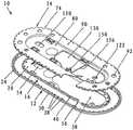
在图1至图6中示出了根据本发明的第一实施例的包装件10。如图1和6所示,包装件10具有基部构件12和缝合线通道盖构件14。A
现在更详细地参照图2和图3,可以看到基部构件12具有顶表面20和底表面22。还可以看到基部构件12具有外周24。还可以看见基部构件12是基本平坦且基本卵形的构件,所述基本平坦且基本卵形的构件具有纵向轴线26。然而,尽管希望基部构件12与包装件10一起是卵形的,但是可以使用其他构造,包括圆形、多边形、带圆角的正方形等等及其组合和其等同。Referring now in more detail to FIGS. 2 and 3 , it can be seen that the
外壁30围绕基部构件12的外周24向上延伸。可以看到外壁30具有底部、内表面32、外表面34和顶部36。外壁30的内表面32是具有多个D形隆起38的异型表面,所述隆起38从基部构件12的顶表面20延伸到外壁30的顶部36。D形隆起38从外壁30突出至少一毫米。The
在基部构件12的外壁30的顶部36处可以设有可选的凹口。这些凹口在此用于保持基部构件12平坦。An optional notch may be provided at the top 36 of the
可以看到内壁40从基部构件12的顶表面20向上延伸。可以看到内壁40具有底部、内表面42、外表面44和顶部46。内壁40的顶部46是由多个凹部48构成的异型表面。内壁40和外壁30大致彼此等间隔,从而在其间形成用于缝合线的缝合线轨道区域(缠绕通道)16。内壁40的顶部46位于外壁30的顶部36下方。因此,内壁40的顶部46可以限定当盖构件14被向下推到基部构件12上至尽可能低的水平时的位置。此外,内壁40可以使缝合线易于取出。The
在内壁40中存在间隙50。在将针放置在包装件10的中部之后,缝合线需要该间隙50以到达缠绕通道。There is a
多个精密孔52延伸穿过基部构件12的底部。精密孔52位于内壁40的内部。卵形驱动销定位孔54同样延伸穿过基部构件12的底部。可以看到驱动销定位孔54沿着纵向轴线26设置在基部构件12的一端并且仍然在内壁40的内部。四个捕获凹陷部56同样延伸穿过基部构件12的底部,所述捕获凹陷部用于将盖构件14固定到基部构件12。捕获凹陷部56布置在基部构件12的内壁40的内表面42附近。然而,尽管期望的是捕获凹陷部56是矩形的,但是也可以使用其他构造,包括卵形、圆形、多边形、具有圆角的正方形等等及其组合和其等同。A plurality of precision holes 52 extend through the bottom of the
此外,在基部构件12的底部有开口58。开口58包括捕获凹陷部56中的一个并且定位成使得间隙50通向开口58。开口58仅覆盖基部构件12的中部并在内壁40的内部。然而,开口58可以分段地到达内壁40的内表面42。In addition, there is an
与根据图1至6的实施例相比,多条空气槽可以延伸穿过基部构件12的底部。那些空气槽应该位于外壁30和内壁40之间。In contrast to the embodiment according to FIGS. 1 to 6 , a plurality of air slots may extend through the bottom of the
现在参照图4和5,可以看到示出了缝合线通道盖构件14。缝合线通道盖构件14具有顶表面70、底表面72和外周74。基部构件12的外壁30的D形隆起38在盖构件14的外周74中具有镜像切口。盖构件14中的那些匹配凹部76在组装时提供了互锁屏障,该互锁屏障将包含尺寸低至10/0的缝合线并将它们保持在包装件10内。可以看到盖构件14为基本扁平且基本卵形的构件,该构件具有纵向轴线78。Referring now to Figures 4 and 5, the suture
盖构件14在其中部具有凹陷区域80。可以看到凹陷区域具有顶表面82、底表面84和外周86,所述外周86对应于基部构件12的内壁40的内表面42。选择凹陷区域80的深度,使得在组装时凹陷区域80的底表面84位于基部构件12的顶表面20上(见图6)。The
在盖构件14的外周74和凹陷区域的外周86之间形成卵形环部分90,所述卵环形部分90覆盖缝合线轨道区域16。在该环形部分90的内部存在多个缝合线缠绕销孔92,所述缝合线缠绕销孔92延伸穿过盖构件14。缝合线缠绕销孔92的优选形状是圆形的,但也可以使用其他形状,例如卵形、八边形、半圆形、多边形、三角形、它们的组合及其等同等等。此外,可以看到缝合线出口94包含在盖构件14的环部分90中。当组装时,环形缝合线出口94位于基部构件12的内壁40的间隙50上方。An
在图5中,可以看到内壁100从凹陷区域80的底表面84向下延伸。可以看到内壁100具有底部、内表面102、外表面104和顶部106。内壁100位于盖构件14的凹陷区域80的外周处。在内壁100的外表面104处设有多个突片构件108。所述突片构件108对应于基部构件12的内壁40的顶部46的凹部76。In FIG. 5 , the
紧固销110从凹陷区域80的底表面84向下延伸。紧固销110具有平坦顶部112。可以看到紧固销110优选地具有圆柱形表面114,但是它们也可以具有平坦外表面。如果需要,紧固销110可以具有用于外表面的其他构造,包括半圆形、多边形、卵形、三角形、它们的组合及其等同等等。带有平坦外表面的紧固销110与带有弯曲外表面的紧固销110的组合也是可以的。当组装包装件10时,紧固销110与基部构件12的精密孔52配合。因此,精密孔52的直径和形状由紧固销110的形状确定。The fastening pins 110 extend downwardly from the
为了将盖构件14锁定到基部构件12上,可以例如通过使用超声波使紧固销110变形。这使紧固销110的顶部112变平和变宽。在紧固销110的顶部112的这种变形之后,基部构件12的精密孔52不会从紧固销110滑落,因此盖构件14被牢固地锁定到基部构件12上。In order to lock the
可以看到销缠绕孔120和122包含在盖构件14的相对两端处。可以看到销缠绕孔120和122延伸穿过盖构件14并沿着其纵向轴线78朝向任一端设置在盖构件14中。销缠绕孔120的形状为卵形,而销缠绕孔122的形状为圆形。然而,可以使用其他几何形状。卵形销缠绕孔120与基部构件14的驱动销定位孔54对准。卵形销缠绕孔120位于盖构件14的凹陷区域80的内部。圆形销缠绕孔122与基部构件12的开口58对准。圆形销缠绕孔122位于盖构件14的第二凹陷区域130的内部,所述第二凹陷区域130也是第一凹陷区域80的一部分。It can be seen that pin wrap holes 120 and 122 are included at opposite ends of the
可以看到第二凹陷区域130具有顶表面132、底表面134和外周136,该外周136对应于基部构件12的开口58的形状。选择第二凹陷区域130的深度,使得在组装时第二凹陷区域130的顶表面132与基部构件12的顶表面20对准。The second recessed
四个钩构件140也从凹陷区域80的底表面84向下延伸。可以看到钩构件140与基部构件12的捕获凹陷部56对准,以便将盖构件14固定到基部构件12上。Four
为了保持对较小针的控制,针存放装置150位于第二凹陷区域130的内部,从所述第二凹陷区域130的顶表面132向上延伸。在图4中,针存放装置150以其优选构造示出为具有竖直悬臂构件152,该竖直悬臂构件152具有V形凹部154,所述V形凹部154留下小的平台以接触针并将其保持在适当位置。与附图中所示的实施例相比,可以设有多于一个的悬臂构件152,以便适应不同尺寸的外科针。盖构件14的第二凹陷区域130的底部中的可选狭缝可以形成突片提升构件156。To maintain control of the smaller needles, the
以下列方式组装本发明的包装件10。为了在包装件10中安装具有安装至一端的外科针的缝合线,将基部构件12安装到传统的可旋转的缠绕固定件中,使得缠绕固定件的缠绕销插入销缠绕孔120、122中。将针放入针存放装置150中。接着,将缝合线从缝合线出口94穿入缠绕通道16中。缝合线通过缝合线控制臂被引导到包装件10中,所述缝合线控制臂将盖构件14提升大约0.05英寸并且当其在固定装置中旋转时在缝合线覆盖构件14和基部构件12之间运行,使得当包装件10旋转时缝合线被完全缠绕到缝合线轨道16中。这可以通过额外的缝合线和额外的针重复。然后可以将印刷盖附接到基部构件12和盖构件14上。然后可以将包含缠绕缝合线和针的包装件10放置在传统的袋或包装件中,以便常规灭菌处理,例如气态消毒剂、高压灭菌、辐射等等。The
当由医生在外科手术中使用时,包装件10被放入无菌场合中。使用传统的针抓持器,外科医生向下推动突片提升构件156,针可以被从针存放装置150抓持并移除。然后拉动针和缝合线远离包装件10,缝合线通过缝合线出口94离开。When used by a physician in a surgical procedure, the
本发明的包装件10的基部构件12可以由常规的可模制材料制成。特别优选使用聚烯烃材料如聚乙烯和聚丙烯、其它热塑性材料和聚酯材料(如尼龙)及其等同。用于基部构件12和盖构件14二者的优选材料是HPDE Dow 25455N。优选地,本发明的基部构件12是注射成型的,然而,基部构件12可以通过其他传统工艺及其等同形成,包括热成型。如果需要,包装件10可以制造成各个独立组件或部件,然后再组装。The
可以包装在本发明的包装件10中的缝合线和针包括传统的外科针和传统的生物可吸收和不可吸收的外科缝合线及其等同。本发明的包装件10可用于包装小直径缝合线,例如USP 10-0,这种小直径缝合线先前难以包装在托盘包装件中,因为缝合线端部或尾部从缝合线轨道区域中出来并因此引起密封问题。使用本发明的包装件10已经克服了这些问题。此外,分配后的记忆性显示减少约50%。Sutures and needles that may be packaged in the
本发明的包装件10也可用于包装诸如USP 2和USP 3的大直径缝合线以及不适合装配在当前现有技术的包装件中的较长长度的缝合线。The
Claims (11)
Translated fromChineseApplications Claiming Priority (2)
| Application Number | Priority Date | Filing Date | Title |
|---|---|---|---|
| EP17002038.2 | 2017-12-19 | ||
| EP17002038.2AEP3501402B1 (en) | 2017-12-19 | 2017-12-19 | Package for sutures and needles |
Publications (2)
| Publication Number | Publication Date |
|---|---|
| CN109928086A CN109928086A (en) | 2019-06-25 |
| CN109928086Btrue CN109928086B (en) | 2020-08-21 |
Family
ID=60702284
Family Applications (1)
| Application Number | Title | Priority Date | Filing Date |
|---|---|---|---|
| CN201811570363.3AActiveCN109928086B (en) | 2017-12-19 | 2018-12-18 | Package for suture and needle |
Country Status (5)
| Country | Link |
|---|---|
| US (1) | US10561414B2 (en) |
| EP (1) | EP3501402B1 (en) |
| CN (1) | CN109928086B (en) |
| CA (1) | CA3025214C (en) |
| ES (1) | ES2820523T3 (en) |
Families Citing this family (3)
| Publication number | Priority date | Publication date | Assignee | Title |
|---|---|---|---|---|
| EP3909518A1 (en)* | 2020-05-14 | 2021-11-17 | B. Braun Surgical, S.A. | Needle holder and package for surgical suture material |
| US20220346778A1 (en)* | 2021-04-29 | 2022-11-03 | Origami Surgical, Inc. | Housing for storing sutures therein, and methods of use therefor |
| US12226939B2 (en)* | 2021-08-02 | 2025-02-18 | Alltrista Plastics, Llc | Method of producing injection molded articles |
Family Cites Families (25)
| Publication number | Priority date | Publication date | Assignee | Title |
|---|---|---|---|---|
| US4424898A (en)* | 1982-04-08 | 1984-01-10 | Ethicon, Inc. | Needle and suture holder and package |
| US4961498A (en) | 1988-08-24 | 1990-10-09 | Ethicon, Inc. | Oval wrap suture package |
| US4967902A (en) | 1989-09-12 | 1990-11-06 | Ethicon, Inc. | One piece channel suture packages |
| US5230424A (en) | 1992-06-19 | 1993-07-27 | Ethicon, Inc. | Multi-strand suture package and cover-latching element |
| JP2852128B2 (en) | 1995-02-10 | 1999-01-27 | メルク エンド カンパニー インコーポレーテッド | Method for producing certain azacyclohexapeptides |
| DE19744543A1 (en)* | 1997-10-09 | 1999-04-22 | Braun Surgical S A B | Suture material dispenser |
| US6047815A (en)* | 1998-08-31 | 2000-04-11 | Ethicon, Inc. | Package for sutures |
| US6135272A (en) | 1999-10-22 | 2000-10-24 | Ethicon, Inc. | Package for sutures |
| DE19959263B4 (en)* | 1999-12-03 | 2005-03-17 | Ethicon Gmbh | Suture packaging |
| US20040129591A1 (en)* | 2000-10-02 | 2004-07-08 | Tomoaki Koseki | Operation sutural needle counter |
| US6463719B2 (en)* | 2000-12-13 | 2002-10-15 | Ethicon | Suture winding machine, suture tray package, and method of winding sutures |
| US6644469B2 (en)* | 2001-07-11 | 2003-11-11 | Ethicon, Inc. | Large needle oval wound plastic suture package |
| US8112973B2 (en)* | 2002-10-04 | 2012-02-14 | Ethicon, Inc. | Method of making a packaged antimicrobial suture |
| US9474524B2 (en)* | 2002-10-04 | 2016-10-25 | Ethicon, Inc. | Packaged antimicrobial medical device having improved shelf life and method of preparing same |
| US9597067B2 (en)* | 2002-10-04 | 2017-03-21 | Ethicon, Inc. | Packaged antimicrobial medical device and method of preparing same |
| US7637369B2 (en)* | 2003-07-18 | 2009-12-29 | Tyco Healthcare Group Lp | Suture packaging |
| US20070227914A1 (en)* | 2006-03-30 | 2007-10-04 | Cerwin Robert J | Suture package |
| US9622743B2 (en) | 2008-10-02 | 2017-04-18 | Covidien Lp | Suture packaging |
| DE102010055048B4 (en)* | 2010-12-17 | 2016-08-18 | Serag-Wiessner Gmbh & Co. Kg | Suture dispenser for surgical suture insertion |
| US9421009B1 (en) | 2011-09-27 | 2016-08-23 | A. Jamie Riley | Suture delivery system |
| US10245025B2 (en)* | 2012-04-06 | 2019-04-02 | Ethicon, Inc. | Packaged antimicrobial medical device having improved shelf life and method of preparing same |
| KR101488777B1 (en)* | 2014-06-19 | 2015-02-04 | (주)에스엠이엔지 | Medical suture packages |
| EP3095392B1 (en) | 2015-05-18 | 2017-11-01 | DS-Technology GmbH | Package for sutures |
| CN206687737U (en)* | 2016-12-31 | 2017-12-01 | 湖南凯利医疗科技有限公司 | Medical suture packing box |
| CN107397567A (en)* | 2017-08-25 | 2017-11-28 | 运怡(北京)医疗器械有限公司 | A kind of surgical suture needle wire wrapping liner plate |
- 2017
- 2017-12-19ESES17002038Tpatent/ES2820523T3/enactiveActive
- 2017-12-19EPEP17002038.2Apatent/EP3501402B1/enactiveActive
- 2018
- 2018-11-26CACA3025214Apatent/CA3025214C/enactiveActive
- 2018-12-18CNCN201811570363.3Apatent/CN109928086B/enactiveActive
- 2018-12-18USUS16/223,366patent/US10561414B2/enactiveActive
Also Published As
| Publication number | Publication date |
|---|---|
| US20190183488A1 (en) | 2019-06-20 |
| EP3501402B1 (en) | 2020-06-17 |
| CA3025214C (en) | 2020-09-01 |
| CN109928086A (en) | 2019-06-25 |
| CA3025214A1 (en) | 2019-06-19 |
| ES2820523T3 (en) | 2021-04-21 |
| US10561414B2 (en) | 2020-02-18 |
| EP3501402A1 (en) | 2019-06-26 |
Similar Documents
| Publication | Publication Date | Title |
|---|---|---|
| US11406376B2 (en) | Suture packaging | |
| US6135272A (en) | Package for sutures | |
| EP1842494B1 (en) | Suture packaging | |
| US6047815A (en) | Package for sutures | |
| EP2119401B1 (en) | Suture packaging | |
| US8746445B2 (en) | Suture packaging | |
| CN109928086B (en) | Package for suture and needle | |
| EP1275343B1 (en) | Armed suture package | |
| JP2009247900A (en) | Suture package for barbed suture | |
| CN110636801B (en) | Suture package | |
| EP3095392B1 (en) | Package for sutures | |
| JP3830572B2 (en) | Center takeout suture package |
Legal Events
| Date | Code | Title | Description |
|---|---|---|---|
| PB01 | Publication | ||
| PB01 | Publication | ||
| SE01 | Entry into force of request for substantive examination | ||
| SE01 | Entry into force of request for substantive examination | ||
| GR01 | Patent grant | ||
| GR01 | Patent grant |