CN109904938B - Matrix network type wireless power supply system for mobile equipment and charging method thereof - Google Patents
Matrix network type wireless power supply system for mobile equipment and charging method thereofDownload PDFInfo
- Publication number
- CN109904938B CN109904938BCN201910169006.4ACN201910169006ACN109904938BCN 109904938 BCN109904938 BCN 109904938BCN 201910169006 ACN201910169006 ACN 201910169006ACN 109904938 BCN109904938 BCN 109904938B
- Authority
- CN
- China
- Prior art keywords
- power supply
- coil
- transmitting
- power
- coils
- Prior art date
- Legal status (The legal status is an assumption and is not a legal conclusion. Google has not performed a legal analysis and makes no representation as to the accuracy of the status listed.)
- Active
Links
- 239000011159matrix materialSubstances0.000titleclaimsabstractdescription92
- 238000000034methodMethods0.000titleclaimsabstractdescription19
- 238000001514detection methodMethods0.000claimsabstractdescription31
- 230000005540biological transmissionEffects0.000claimsabstractdescription17
- 230000009977dual effectEffects0.000claimsdescription8
- 238000004364calculation methodMethods0.000claimsdescription5
- 230000008859changeEffects0.000claimsdescription4
- 229910001035Soft ferriteInorganic materials0.000claimsdescription3
- 238000006243chemical reactionMethods0.000claimsdescription3
- 239000000463materialSubstances0.000claimsdescription3
- 230000005855radiationEffects0.000abstract1
- 230000008878couplingEffects0.000description10
- 238000010168coupling processMethods0.000description10
- 238000005859coupling reactionMethods0.000description10
- 230000005670electromagnetic radiationEffects0.000description8
- 238000010586diagramMethods0.000description6
- 230000007246mechanismEffects0.000description3
- 230000007423decreaseEffects0.000description2
- 238000012423maintenanceMethods0.000description2
- 230000008569processEffects0.000description2
- 230000002411adverseEffects0.000description1
- 238000004458analytical methodMethods0.000description1
- 239000003990capacitorSubstances0.000description1
- 230000007547defectEffects0.000description1
- 230000000694effectsEffects0.000description1
- 230000005611electricityEffects0.000description1
- 238000005516engineering processMethods0.000description1
- 238000003912environmental pollutionMethods0.000description1
- 230000004907fluxEffects0.000description1
- 239000000446fuelSubstances0.000description1
- 230000020169heat generationEffects0.000description1
- 230000006698inductionEffects0.000description1
- 230000016507interphaseEffects0.000description1
Images


Classifications
- Y—GENERAL TAGGING OF NEW TECHNOLOGICAL DEVELOPMENTS; GENERAL TAGGING OF CROSS-SECTIONAL TECHNOLOGIES SPANNING OVER SEVERAL SECTIONS OF THE IPC; TECHNICAL SUBJECTS COVERED BY FORMER USPC CROSS-REFERENCE ART COLLECTIONS [XRACs] AND DIGESTS
- Y02—TECHNOLOGIES OR APPLICATIONS FOR MITIGATION OR ADAPTATION AGAINST CLIMATE CHANGE
- Y02T—CLIMATE CHANGE MITIGATION TECHNOLOGIES RELATED TO TRANSPORTATION
- Y02T10/00—Road transport of goods or passengers
- Y02T10/60—Other road transportation technologies with climate change mitigation effect
- Y02T10/70—Energy storage systems for electromobility, e.g. batteries
- Y—GENERAL TAGGING OF NEW TECHNOLOGICAL DEVELOPMENTS; GENERAL TAGGING OF CROSS-SECTIONAL TECHNOLOGIES SPANNING OVER SEVERAL SECTIONS OF THE IPC; TECHNICAL SUBJECTS COVERED BY FORMER USPC CROSS-REFERENCE ART COLLECTIONS [XRACs] AND DIGESTS
- Y02—TECHNOLOGIES OR APPLICATIONS FOR MITIGATION OR ADAPTATION AGAINST CLIMATE CHANGE
- Y02T—CLIMATE CHANGE MITIGATION TECHNOLOGIES RELATED TO TRANSPORTATION
- Y02T10/00—Road transport of goods or passengers
- Y02T10/60—Other road transportation technologies with climate change mitigation effect
- Y02T10/7072—Electromobility specific charging systems or methods for batteries, ultracapacitors, supercapacitors or double-layer capacitors
- Y—GENERAL TAGGING OF NEW TECHNOLOGICAL DEVELOPMENTS; GENERAL TAGGING OF CROSS-SECTIONAL TECHNOLOGIES SPANNING OVER SEVERAL SECTIONS OF THE IPC; TECHNICAL SUBJECTS COVERED BY FORMER USPC CROSS-REFERENCE ART COLLECTIONS [XRACs] AND DIGESTS
- Y02—TECHNOLOGIES OR APPLICATIONS FOR MITIGATION OR ADAPTATION AGAINST CLIMATE CHANGE
- Y02T—CLIMATE CHANGE MITIGATION TECHNOLOGIES RELATED TO TRANSPORTATION
- Y02T90/00—Enabling technologies or technologies with a potential or indirect contribution to GHG emissions mitigation
- Y02T90/10—Technologies relating to charging of electric vehicles
- Y02T90/14—Plug-in electric vehicles
Landscapes
- Charge And Discharge Circuits For Batteries Or The Like (AREA)
Abstract
Translated fromChinese
Description
Translated fromChinese技术领域technical field
本发明属于无线电能传输技术领域,特别是涉及一种应用于移动设备的矩阵网络式无线供电系统及其充电方法。The invention belongs to the technical field of wireless power transmission, and in particular relates to a matrix network wireless power supply system and a charging method thereof applied to a mobile device.
背景技术Background technique
随着环境污染与石油危机的爆发,凭借零排放、能量利用率高、能源来源广泛的优点,电能取代传统燃油作为移动设备的动力来源已成为未来的必然趋势。然而,传统的接触式充电方式存在许多问题:(1)充电不便,受接口的限制,充电过程繁琐;(2)维护成本高,充电插头存在摩擦损耗,需要频繁维护;(3)安全性差,供电接口和充电插头均有高压,会对操作人员产生安全威胁。而采用无线电能传输技术进行无线供电则可以很好地解决上述问题。With the outbreak of environmental pollution and oil crisis, it has become an inevitable trend in the future to replace traditional fuel with electricity as the power source for mobile devices, with the advantages of zero emissions, high energy utilization, and wide energy sources. However, the traditional contact charging method has many problems: (1) charging is inconvenient, limited by the interface, and the charging process is cumbersome; (2) the maintenance cost is high, and the charging plug has friction loss, requiring frequent maintenance; (3) poor safety, Both the power supply interface and the charging plug have high voltage, which will pose a safety threat to the operator. The use of wireless power transmission technology for wireless power supply can solve the above problems well.
国内外各研究机构针对移动设备的无线供电系统进行了许多研究,丰田公司在2014年公开的专利(公开号为WO2014/118615A2)中提出了一种无线供电系统,但该系统中发射线圈产生的磁场分布不均匀,接收线圈只有与发射端正对时才能高效充电,抗偏移能力差;福州大学在2013年申请公布的专利(专利号为CN 102946154)中提出了一种矩形阵列线圈品字型分布的无线电能传输系统,该系统抗偏移能力强,但需要导通全部的发射线圈,传输效率较低,电磁辐射严重。韩国KAIST在2017年发表的文献《Six Degrees of FreedomWide-range IPT for Multiple IoT by DQ Rotating Magnetic Field》中提出了一种具有dq发射线圈的无线供电系统,该系统同样需要导通充电区域内全部的发射线圈,传输效率低。日本名古屋工业大学在2013年发表的文献《A Consideration of EfficiencyImprovement of Transmitting Coil Array in Wireless Power Transfer withMagnetically Coupled Resonance》中提出了一种矩阵网络式磁耦合机构,但是该结构中多相阵列发射线圈存在相间耦合,导致系统谐振频率偏谐,效率较低。Various research institutions at home and abroad have carried out a lot of research on the wireless power supply system of mobile devices. Toyota proposed a wireless power supply system in the patent published in 2014 (publication number is WO2014/118615A2), but the transmission coil in the system produces a wireless power supply system. The magnetic field is unevenly distributed, and the receiving coil can be charged efficiently only when it is directly facing the transmitting end, and the anti-offset ability is poor; Fuzhou University proposed a rectangular array coil in the patent published in 2013 (patent number CN 102946154) Distributed wireless power transmission system, the system has strong anti-offset ability, but needs to turn on all the transmitting coils, the transmission efficiency is low, and the electromagnetic radiation is serious. In the document "Six Degrees of FreedomWide-range IPT for Multiple IoT by DQ Rotating Magnetic Field" published by South Korea's KAIST in 2017, a wireless power supply system with a dq transmitter coil is proposed, which also needs to conduct all the power supply in the charging area. The transmitting coil has low transmission efficiency. In the document "A Consideration of EfficiencyImprovement of Transmitting Coil Array in Wireless Power Transfer with Magnetically Coupled Resonance" published by Nagoya Institute of Technology in Japan in 2013, a matrix network magnetic coupling mechanism was proposed, but in this structure, the transmitting coil of the polyphase array has interphase Coupling, causing the system resonant frequency to be detuned, and the efficiency is low.
综上所述,对于应用于移动设备的无线供电系统,目前存在技术缺陷如下:To sum up, for the wireless power supply system applied to mobile devices, the current technical defects are as follows:
1、传输效率低。充电区域内的发射线圈需要全部导通,发射线圈上损耗大,导致发热严重,系统传输效率低。1. Low transmission efficiency. The transmitting coils in the charging area need to be all turned on, and the losses on the transmitting coils are large, resulting in serious heat generation and low transmission efficiency of the system.
2、电磁辐射严重。在接收线圈外侧区域,由于发射线圈产生的主磁场没有被有效利用,会产生较大电磁辐射,对周围人体或生物产生安全威胁。2. Serious electromagnetic radiation. In the outer area of the receiving coil, since the main magnetic field generated by the transmitting coil is not effectively utilized, large electromagnetic radiation will be generated, which will pose a safety threat to the surrounding human body or organisms.
3、抗偏移能力差。接收线圈只有与发射端正对时才能高效充电,出现偏移后,互感迅速降低,系统的输出功率下降;3. Poor anti-offset ability. The receiving coil can only be efficiently charged when it is directly opposite to the transmitting end. After the offset occurs, the mutual inductance decreases rapidly, and the output power of the system decreases;
4、矩阵线圈之间存在相互耦合。线圈之间的相互耦合会使系统的谐振频率出现偏移,增大无功功率,降低系统的有功输出。4. There is mutual coupling between the matrix coils. The mutual coupling between the coils will shift the resonant frequency of the system, increase the reactive power, and reduce the active output of the system.
发明内容SUMMARY OF THE INVENTION
本发明目的是为了解决目前应用于移动设备的无线供电系统中传输效率低、抗偏移能力差、电磁辐射严重等问题,提出了一种应用于移动设备的矩阵网络式无线供电系统及其充电方法。The purpose of the present invention is to solve the problems of low transmission efficiency, poor anti-offset capability, serious electromagnetic radiation, etc. in the current wireless power supply system applied to mobile equipment, and proposes a matrix network wireless power supply system applied to mobile equipment and its charging. method.
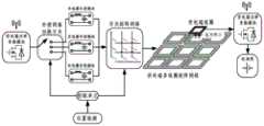
本发明是通过以下技术方案实现的,本发明提出一种应用于移动设备的矩阵网络式无线供电系统,所述无线供电系统由发射端供电装置、接收端受电装置和检测控制装置三部分组成,所述发射端供电装置安装在充电区域的地面下方,所述接收端受电装置安装在移动设备上,所述检测控制装置的输出端与所述发射端供电装置连接;The present invention is achieved through the following technical solutions. The present invention proposes a matrix network wireless power supply system applied to mobile equipment. The wireless power supply system is composed of three parts: a transmitting end power supply device, a receiving end power receiving device and a detection and control device , the transmitting end power supply device is installed under the ground of the charging area, the receiving end power receiving device is installed on the mobile device, and the output end of the detection control device is connected to the transmitting end power supply device;
所述的发射端供电装置包括供电端功率变化模块、供电端多线圈矩阵网络1和供电端磁芯2;其中供电端功率变换模块的输出端经过检测控制装置后与供电端多线圈矩阵网络1连接,供电端磁芯2铺设在供电端多线圈矩阵网络1下方;The transmitting end power supply device includes a power supply end power change module, a power supply end
所述的接收端受电装置包括受电端线圈4、受电端磁芯3、受电端补偿网络、受电端功率变换器和电池组;其中受电端线圈4经受电端补偿网络后与受电端功率变换器连接,转换为直流输出向电池组充电;所述受电端磁芯3铺设于受电端线圈4的上方;The power receiving device at the receiving end includes a power receiving
所述检测控制装置包括位置检测装置、控制单元、切换开关、供电端谐振补偿模块和开关矩阵网络;位置检测装置经控制单元分别连接切换开关和开关矩阵网络,用于控制供电端谐振补偿模块和供电端多线圈矩阵网络1工作。The detection and control device includes a position detection device, a control unit, a switch, a power supply end resonance compensation module and a switch matrix network; the position detection device is respectively connected to the switch switch and the switch matrix network through the control unit, and is used to control the power supply end resonance compensation module and the switch matrix network. The power supply end
进一步地,所述供电端多线圈矩阵网络1的排布方式为紧贴排布方式或重叠排布方式。Further, the arrangement of the
进一步地,所述供电端多线圈矩阵网络1由N×M个独立平面矩形线圈组成,其中N和M均为正整数,铺设在供电端磁芯2上方;在平面内呈矩阵阵列排布,且相邻的两个线圈紧密排列在一起,或,任意相邻的两个线圈中,相邻的导线在空间上水平对齐,并沿竖直方向叠放在一起;所有的N×M个矩形线圈的尺寸和形状参数完全相同,导线均为利兹线,其粗细和股数均相同;所有矩形线圈的匝数均为n匝,其中n为正整数,线圈匝数由输出功率、输出电流大小及导线的线径综合决定。Further, the power supply end
进一步地,所述控制单元为DSP数字控制芯片,输入端连接位置检测装置,输出端分别连接切换开关和开关矩阵网络,根据受电端的位置信息,经过计算比较,确定系统使用的供电策略,之后根据供电策略分别控制切换开关和开关矩阵网络工作。Further, the control unit is a DSP digital control chip, the input terminal is connected to the position detection device, and the output terminal is respectively connected to the switch and the switch matrix network. According to the power supply strategy, the switching switch and the switch matrix network are respectively controlled to work.
进一步地,所述供电策略包括单发射线圈独立工作供电策略、双发射线圈协同工作供电策略和四发射线圈协同工作供电策略。Further, the power supply strategy includes a single transmitter coil independent work power supply strategy, a dual transmitter coil cooperative work power supply strategy, and a four transmitter coil cooperative work power supply strategy.
进一步地,所述供电端谐振补偿模块包括单线圈补偿模块、双线圈补偿模块和四线圈补偿模块,输入端连接切换开关,输出端连接开关矩阵网络;切换开关会根据控制信号切换不同的补偿模块接入主电路中工作,此时其余的补偿模块不工作。Further, the power supply end resonance compensation module includes a single-coil compensation module, a double-coil compensation module and a four-coil compensation module, the input end is connected to a switch, and the output end is connected to a switch matrix network; the switch will switch different compensations according to the control signal. The module is connected to the main circuit to work, and the rest of the compensation modules do not work at this time.
进一步地,所述单发射线圈独立工作供电策略:当受电端位于某个发射线圈的正上方位置附近时,受电端线圈4与该发射线圈磁场耦合,为了提高系统传输效率,系统进入单发射线圈独立工作模式,控制单元控制切换开关使单线圈补偿模块接入主电路中,开关矩阵网络控制对应的单个发射线圈导通以产生高频交变磁场,在受电端线圈4中产生感应电势向负载供电,此时其余发射线圈均处于断路状态;Further, the single-transmitting coil works independently of the power supply strategy: when the receiving end is located near the position directly above a certain transmitting coil, the receiving
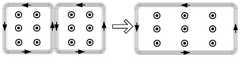
所述双发射线圈协同工作供电策略:当受电端位于两个发射线圈的中间位置区域时,受电端线圈4与所述两个发射线圈磁场耦合,系统进入双发射线圈协同工作模式,控制切换开关使双线圈补偿模块串入主电路中,并通过开关矩阵网络使对应的两个发射线圈串联后导通,且线圈中电流方向相同;此时两个发射线圈中相邻的两束导线中电流幅值相等,方向相反,产生的磁场相互抵消,因此,协同工作的两个发射线圈可以等效为一个宽度增加一倍的大矩形线圈,产生方向相同的合成磁场向受电端供电以保证系统的输出功率;The dual-transmitting coils work together power supply strategy: when the power-receiving end is located in the middle area of the two transmitting coils, the receiving-
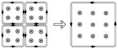
所述四发射线圈协同工作供电策略:当受电端侧移至四个发射线圈的中心位置区域时,受电端线圈4同时与所述四个发射线圈磁场耦合,为了保证输出功率不降低,系统进入四发射线圈协同工作模式,控制切换开关使四线圈补偿模块串入主电路中,并通过开关矩阵网络使对应的四个发射线圈串联后导通,并保证四个线圈中电流的方向相同;此时不同的线圈中相邻的两束导线中电流幅值相等,方向相反,产生的磁场相互抵消,四个发射线圈可以等效为一个尺寸增大4倍的大矩形线圈,产生方向相同的合成磁场向受电端供电。The power supply strategy of the four transmitting coils working together: when the receiving end side moves to the central position of the four transmitting coils, the receiving
进一步地,所述开关矩阵网络中使用MOSFET开关或IGBT开关,根据控制单元产生的控制信号,开关矩阵网络中对应的开关工作,导通与受电端距离最近的单个或多个发射线圈向受电端传输能量。Further, MOSFET switches or IGBT switches are used in the switch matrix network, and according to the control signal generated by the control unit, the corresponding switches in the switch matrix network work, and the single or multiple transmitter coils that are closest to the receiving end are turned on to the receiving end. The electrical terminal transmits energy.
进一步地,所述供电端磁芯2和受电端磁芯3均为平板型磁芯,材料为软磁铁氧体。Further, the
本发明还提出一种应用于移动设备的矩阵网络式无线供电系统的充电方法,当移动设备进入充电区域后,通过位置检测装置检测受电端相对于供电端多线圈矩阵网络的位置,并将位置信息传递给控制单元进行计算,当受电端位于某个发射线圈的正上方位置时,采用单发射线圈独立工作供电策略;当受电端位于两个发射线圈的中间位置区域时,采用双发射线圈协同工作策略;当受电端侧移至四个发射线圈的中心位置区域时,采用四发射线圈协同工作策略;确定系统的供电策略后,控制单元向切换开关传递控制信号,控制补偿谐振网络模块中对应的补偿模块接入主电路中,补偿系统的无功功率;同时,控制单元向开关矩阵网络传递控制信号,经过驱动电路后控制对应的MOSFET或IGBT开关工作,改变供电端发射线圈的导通个数和连接方式,使与受电端距离最近的单个或多个发射线圈工作,产生高频磁场向受电端供电,实现可移动设备的高效灵活无线供电。The present invention also provides a charging method for a matrix network wireless power supply system applied to a mobile device. When the mobile device enters the charging area, the position of the power receiving end relative to the power supply end multi-coil matrix network is detected by the position detection device, and the The position information is transmitted to the control unit for calculation. When the receiving end is located directly above a certain transmitting coil, a single transmitting coil is used for independent power supply strategy; when the receiving end is located in the middle of the two transmitting coils, the dual Cooperative working strategy of transmitting coils; when the receiving end side moves to the center of the four transmitting coils, the cooperative working strategy of four transmitting coils is adopted; after determining the power supply strategy of the system, the control unit transmits a control signal to the switch to control the compensation resonance The corresponding compensation module in the network module is connected to the main circuit to compensate the reactive power of the system; at the same time, the control unit transmits a control signal to the switch matrix network, and controls the corresponding MOSFET or IGBT switch to work after passing through the driving circuit, and changes the power supply end transmitting coil. The number of conduction and the connection method of the device can make the single or multiple transmitter coils closest to the receiving end work, generate high-frequency magnetic field to supply power to the receiving end, and realize efficient and flexible wireless power supply of mobile devices.
本发明与现有技术相比,具有如下优点:Compared with the prior art, the present invention has the following advantages:
1、抗偏移能力强。充电区域内任意位置均能实现稳定的功率输出;1. Strong anti-offset ability. Stable power output can be achieved anywhere in the charging area;
2、充电效率高、电磁兼容性好。仅与接收线圈耦合程度最高的单个或多个线圈供电,降低了系统损耗和电磁辐射。2. High charging efficiency and good electromagnetic compatibility. Only the single or multiple coils that are most coupled to the receiving coil are powered, reducing system losses and electromagnetic radiation.
3、矩阵线圈间无需考虑解耦问题。通过开关矩阵网络和补偿网络切换开关,协同工作的多个发射线圈间的耦合电感可以由谐振电容进行补偿,消除了无功功率,降低了逆变源的容量。3. There is no need to consider the decoupling problem between the matrix coils. By switching the switch between the switch matrix network and the compensation network, the coupled inductance between the multiple transmitting coils working together can be compensated by the resonance capacitor, which eliminates the reactive power and reduces the capacity of the inverter source.
附图说明Description of drawings
图1为本发明所述应用于移动设备的矩阵网络式无线供电系统原理图;1 is a schematic diagram of a matrix network wireless power supply system applied to a mobile device according to the present invention;
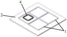
图2为本发明所述的无线供电系统中磁耦合机构的结构视图;2 is a structural view of a magnetic coupling mechanism in the wireless power supply system according to the present invention;
图3为图2的主视图;Fig. 3 is the front view of Fig. 2;
图4为本发明所述单矩形发射线圈独立工作时的供电方式示意图;4 is a schematic diagram of a power supply mode when the single rectangular transmitting coil of the present invention works independently;
图5为本发明所述双矩形发射线圈协同工作时的供电方式示意图;FIG. 5 is a schematic diagram of the power supply mode when the double rectangular transmitting coils work together according to the present invention;
图6为本发明所述双矩形发射线圈协同工作时的磁场分布示意图;6 is a schematic diagram of the magnetic field distribution when the double rectangular transmitting coils of the present invention work together;
图7为本发明所述四矩形发射线圈协同工作时的供电方式示意图;7 is a schematic diagram of the power supply mode when the four rectangular transmitting coils work together according to the present invention;
图8为本发明所述四矩形发射线圈协同工作时的磁场分布示意图;8 is a schematic diagram of the magnetic field distribution when the four rectangular transmitting coils of the present invention work together;
图9为本发明所述线圈矩阵重叠排布时磁耦合机构的结构视图;FIG. 9 is a structural view of the magnetic coupling mechanism when the coil matrices of the present invention are arranged in an overlapping manner;
图10为图9的俯视图;Fig. 10 is the top view of Fig. 9;
图11为图9的主视图。FIG. 11 is a front view of FIG. 9 .
图中:1—供电端多线圈矩阵网络;2—供电端磁芯;3—受电端磁芯;4—受电端线圈。In the figure: 1—multi-coil matrix network at the power supply end; 2—the magnetic core at the power supply end; 3—the magnetic core at the receiving end; 4—the coil at the receiving end.
具体实施方式Detailed ways
下面将结合本发明实施例中的附图对本发明实施例中的技术方案进行清楚、完整地描述,显然,所描述的实施例仅仅是本发明一部分实施例,而不是全部的实施例。基于本发明中的实施例,本领域普通技术人员在没有做出创造性劳动前提下所获得的所有其他实施例,都属于本发明保护的范围。The technical solutions in the embodiments of the present invention will be clearly and completely described below with reference to the accompanying drawings in the embodiments of the present invention. Obviously, the described embodiments are only a part of the embodiments of the present invention, but not all of the embodiments. Based on the embodiments of the present invention, all other embodiments obtained by those of ordinary skill in the art without creative efforts shall fall within the protection scope of the present invention.
结合图1-11说明本发明具体实施方式,本发明提出一种应用于移动设备的矩阵网络式无线供电系统,所述无线供电系统如图1所示,由发射端供电装置、接收端受电装置和检测控制装置三部分组成,所述发射端供电装置安装在充电区域的地面下方,所述接收端受电装置安装在移动设备上,所述检测控制装置的输出端与所述发射端供电装置连接;根据受电端位置来控制供电端的供电方式;The specific embodiments of the present invention will be described with reference to FIGS. 1-11. The present invention proposes a matrix network wireless power supply system applied to mobile devices. As shown in FIG. 1, the wireless power supply system is powered by a transmitter power supply device and a receiver end. The device and the detection and control device are composed of three parts. The transmitting end power supply device is installed under the ground of the charging area, the receiving end power receiving device is installed on the mobile device, and the output end of the detection and control device supplies power to the transmitting end. Device connection; control the power supply mode of the power supply terminal according to the position of the power receiving terminal;
所述的发射端供电装置包括供电端功率变化模块、供电端多线圈矩阵网络1和供电端磁芯2;其中供电端功率变换模块的输出端经过检测控制装置后与供电端多线圈矩阵网络1连接,向发射线圈供电;供电端磁芯2铺设在供电端多线圈矩阵网络1下方;The transmitting end power supply device includes a power supply end power change module, a power supply end
所述的接收端受电装置包括受电端线圈4、受电端磁芯3、受电端补偿网络、受电端功率变换器和电池组;其中受电端线圈4为多匝矩形线圈,经受电端补偿网络后与受电端功率变换器连接,转换为直流输出向电池组充电;所述受电端磁芯3铺设于受电端线圈4的上方,用于约束磁力线走向,提高系统的耦合系数,同时屏蔽漏磁通,减小电磁辐射;The power receiving device at the receiving end includes a power receiving
所述检测控制装置包括位置检测装置、控制单元、切换开关、供电端谐振补偿模块和开关矩阵网络;位置检测装置经控制单元分别连接切换开关和开关矩阵网络,用于控制供电端谐振补偿模块和供电端多线圈矩阵网络1工作,其中切换开关控制供电端谐振补偿模块,开关矩阵网络控制供电端多线圈矩阵网络1。The detection and control device includes a position detection device, a control unit, a switch, a power supply end resonance compensation module and a switch matrix network; the position detection device is respectively connected to the switch switch and the switch matrix network through the control unit, and is used to control the power supply end resonance compensation module and the switch matrix network. The power supply end
所述供电端多线圈矩阵网络1的排布方式为紧贴排布方式或重叠排布方式。所示重叠排布方式主要应用于发射线圈匝数较多的情况下;当发射线圈匝数增多后,线圈宽度增加,两个发射线圈中相邻导线的水平间距增大,导致它们在空间中激发的磁场无法完全抵消,减小了受电端线圈4与发射线圈间的互感,降低了系统的输出功率和传输效率;而使用重叠排布方式后,相邻的两束导线在竖直方向上叠放在一起,其间距极小,可以有效地解决线圈匝数增多带来的不利影响。The arrangement of the
所述供电端多线圈矩阵网络1由N×M个独立平面矩形线圈组成,其中N和M均为正整数,铺设在供电端磁芯2上方;在平面内呈矩阵阵列排布,且相邻的两个线圈紧密排列在一起构成大面积的充电区域,如图2和图3所示,或,任意相邻的两个线圈中,相邻的导线在空间上水平对齐,并沿竖直方向叠放在一起,如图9所示,使用重叠排布方式后,两个发射线圈中相邻的两束导线在空间上紧贴在一起,线宽减小,如图10所示;同时,供电端多线圈矩阵网络1在供电端磁芯2上分两层铺设,且相邻的发射线圈会分别铺设在上下两层,如图11所示;所有的N×M个矩形线圈的尺寸和形状参数完全相同,导线均为利兹线,其粗细和股数均相同;所有矩形线圈的匝数均为n匝,其中n为正整数,线圈匝数由输出功率、输出电流大小及导线的线径综合决定。通过开关矩阵网络,每个矩形线圈既可以独立供电工作,也可以串联协同供电工作;所有的矩形线圈缠绕方向均相同,当多个发射线圈协同工作时,其产生的磁场方向均相同;所述供电端磁芯2铺设在多线圈矩阵网络下方,面积略大于线圈矩阵网络,其作用为约束发射线圈产生的磁力线走向,提高系统耦合系数和互感,同时减小发射线圈产生的电磁辐射。The power supply end
所述控制单元为高性能DSP数字控制芯片,输入端连接位置检测装置,输出端分别连接切换开关和开关矩阵网络,根据受电端的位置信息,经过计算比较,确定系统使用的供电策略,之后根据供电策略分别控制切换开关和开关矩阵网络工作。所述位置检测装置可以使用硬件检测装置,包括红外检测装置、光电检测装置等,通过外部信号来获得受电端的位置信息;也可以使用软件检测的方法省去位置检测装置,所述软件检测方法指的是通过DSP数字控制芯片,逐个导通供电端线圈矩阵网络中的每一个发射线圈,根据交流阻抗理论,受电端与发射线圈的距离越近,互感越大,对应反射阻抗越高,相同输入电压时线圈中流过的电流越小,通过检测每个线圈中电流的幅值,经计算后获得受电端的位置信息。The control unit is a high-performance DSP digital control chip, the input terminal is connected to the position detection device, and the output terminal is respectively connected to the switch and the switch matrix network. The power supply strategy controls the work of the switch and switch matrix network respectively. The position detection device can use hardware detection devices, including infrared detection devices, photoelectric detection devices, etc., to obtain the position information of the power receiving end through external signals; it is also possible to use a software detection method to omit the position detection device. The software detection method It refers to turning on each transmitting coil in the coil matrix network of the power supply end one by one through the DSP digital control chip. According to the AC impedance theory, the closer the distance between the receiving end and the transmitting coil, the greater the mutual inductance and the higher the corresponding reflection impedance. When the input voltage is the same, the smaller the current flowing through the coil, the position information of the power receiving end is obtained after calculation by detecting the amplitude of the current in each coil.
控制单元根据受电端的位置信息,经过计算分析来确定系统使用的工作模式:受电端位于单个发射线圈的正上方位置附近时,系统使用单发射线圈独立工作供电策略,如图4所示;受电端位于两个阵列线圈的中间位置区域时,系统使用双发射线圈协同工作供电策略,如图5所示;受电端偏移至四个相邻的发射线圈的中心位置区域时,系统使用四发射线圈协同工作供电策略,如图7所示;根据选择的供电策略,分别控制切换开关和开关矩阵网络工作。According to the position information of the receiving end, the control unit determines the working mode used by the system through calculation and analysis: when the receiving end is located near the position directly above a single transmitting coil, the system uses a single transmitting coil to work independently for power supply, as shown in Figure 4; When the receiving end is located in the middle area of the two array coils, the system uses the power supply strategy of dual transmitting coils to work together, as shown in Figure 5; when the receiving end is shifted to the center area of the four adjacent transmitting coils, the system The four transmitting coils are used to work together as a power supply strategy, as shown in Figure 7; according to the selected power supply strategy, the switching switch and the switch matrix network are controlled to work separately.
所述供电策略包括单发射线圈独立工作供电策略、双发射线圈协同工作供电策略和四发射线圈协同工作供电策略。The power supply strategies include a single transmitter coil independent work power supply strategy, a dual transmitter coil cooperative work power supply strategy, and a four transmitter coil cooperative work power supply strategy.
所述供电端谐振补偿模块包括单线圈补偿模块、双线圈补偿模块和四线圈补偿模块,输入端连接切换开关,输出端连接开关矩阵网络;切换开关会根据控制信号切换不同的补偿模块接入主电路中工作,此时其余的补偿模块不工作。The power supply end resonance compensation module includes a single-coil compensation module, a double-coil compensation module and a four-coil compensation module, the input end is connected to the switch, and the output end is connected to the switch matrix network; the switch will switch the access of different compensation modules according to the control signal It works in the main circuit, and the rest of the compensation modules do not work at this time.
所述单发射线圈独立工作供电策略:当受电端位于某个发射线圈的正上方位置附近时,受电端线圈4与该发射线圈磁场耦合,为了提高系统传输效率,系统进入单发射线圈独立工作模式,控制单元控制切换开关使单线圈补偿模块接入主电路中,开关矩阵网络控制对应的单个发射线圈导通以产生高频交变磁场,在受电端线圈4中产生感应电势向负载供电,此时其余发射线圈均处于断路状态;The single-transmitting coil independent working power supply strategy: when the receiving end is located near the position directly above a transmitting coil, the receiving-
所述双发射线圈协同工作供电策略:当受电端位于两个发射线圈的中间位置区域时,受电端线圈4与所述两个发射线圈磁场耦合,系统进入双发射线圈协同工作模式,控制切换开关使双线圈补偿模块串入主电路中,并通过开关矩阵网络使对应的两个发射线圈串联后导通,且线圈中电流方向相同;此时两个发射线圈中相邻的两束导线中电流幅值相等,方向相反,产生的磁场相互抵消,如图6所示,中间相邻的两束导线可以忽略,因此,协同工作的两个发射线圈可以等效为一个宽度增加一倍的大矩形线圈,产生方向相同的合成磁场向受电端供电以保证系统的输出功率;The dual-transmitting coils work together power supply strategy: when the power-receiving end is located in the middle area of the two transmitting coils, the receiving-
所述四发射线圈协同工作供电策略:当受电端侧移至四个发射线圈的中心位置区域时,受电端线圈4同时与所述四个发射线圈磁场耦合,为了保证输出功率不降低,系统进入四发射线圈协同工作模式,控制切换开关使四线圈补偿模块串入主电路中,并通过开关矩阵网络使对应的四个发射线圈串联后导通,并保证四个线圈中电流的方向相同;此时不同的线圈中相邻的两束导线中电流幅值相等,方向相反,产生的磁场相互抵消,四个发射线圈可以等效为一个尺寸增大4倍的大矩形线圈,如图8所示,产生方向相同的合成磁场向受电端供电。The power supply strategy of the four transmitting coils working together: when the receiving end side moves to the central position of the four transmitting coils, the receiving
所述开关矩阵网络中使用MOSFET开关或IGBT开关,根据控制单元产生的控制信号,开关矩阵网络中对应的开关工作,导通与受电端距离最近的单个或多个发射线圈向受电端传输能量。A MOSFET switch or an IGBT switch is used in the switch matrix network. According to the control signal generated by the control unit, the corresponding switch in the switch matrix network works, and the single or multiple transmitter coils closest to the power receiving terminal are turned on to transmit the transmission to the power receiving terminal. energy.
所述供电端磁芯2和受电端磁芯3均为平板型磁芯,材料为软磁铁氧体。The
本发明还提出一种应用于移动设备的矩阵网络式无线供电系统的充电方法,通过检测受电端相对于供电端矩阵线圈网络的位置,采用不同的供电策略,控制供电端发射线圈的连接方式和导通个数,以实现受电端在充电区域内任意位置均可以实现稳定功率输出和高效率的无线充电;具体为:当移动设备进入充电区域后,通过位置检测装置检测受电端相对于供电端多线圈矩阵网络的位置,并将位置信息传递给控制单元进行计算,当受电端位于某个发射线圈的正上方位置附近时,采用单发射线圈独立工作供电策略;当受电端位于两个发射线圈的中间位置区域时,采用双发射线圈协同工作策略;当受电端侧移至四个发射线圈的中心位置区域时,采用四发射线圈协同工作策略;不同供电策略下,多线圈矩阵网络中同时工作的线圈个数不同,对应的发射线圈自感也不同,需要分别配置对应的补偿网络,因此确定系统的供电策略后,控制单元向切换开关传递控制信号,控制补偿谐振网络模块中对应的补偿模块接入主电路中,补偿系统的无功功率;无线供电系统正常工作时,除了需要的工作发射线圈外,其余所有发射线圈均处于断路状态,消除了发射线圈相间互感的影响;而协同运行的多个发射线圈经开关矩阵网络串联在一起,相间互感转换为线圈自感,可以通过补偿模块中的电容进行补偿;同时,控制单元向开关矩阵网络传递控制信号,经过驱动电路后控制对应的MOSFET或IGBT开关工作,改变供电端发射线圈的导通个数和连接方式,使与受电端距离最近的单个或多个发射线圈工作,产生高频磁场向受电端供电,实现可移动设备的高效灵活无线供电。由于无线供电系统在工作时只有与受电端线圈4耦合程度最高的单个或多个线圈供电,其余线圈不通电,故系统产生的电磁辐射小,线圈损耗降低,传输效率得以提高。The invention also provides a charging method for a matrix network wireless power supply system applied to a mobile device. By detecting the position of the power receiving end relative to the matrix coil network of the power supply end, different power supply strategies are adopted to control the connection mode of the transmitting coil of the power supply end. and the number of conduction, so that the power receiving end can achieve stable power output and high-efficiency wireless charging at any position in the charging area; specifically: when the mobile device enters the charging area, the position detection device detects the relative position of the receiving end. The position of the multi-coil matrix network at the power supply end, and the position information is transmitted to the control unit for calculation. When the power receiving end is located near the position directly above a certain transmitting coil, a single transmitting coil works independently for power supply strategy; When it is located in the middle position of the two transmitter coils, the cooperative work strategy of the two transmitter coils is adopted; when the receiving end is moved to the central position of the four transmitter coils, the cooperative work strategy of the four transmitter coils is adopted; under different power supply strategies, multiple transmitter coils work cooperatively. The number of coils working at the same time in the coil matrix network is different, and the corresponding self-inductance of the transmitting coil is also different, and the corresponding compensation network needs to be configured respectively. Therefore, after determining the power supply strategy of the system, the control unit transmits a control signal to the switch to control the compensation resonant network. The corresponding compensation module in the module is connected to the main circuit to compensate the reactive power of the system; when the wireless power supply system is working normally, except for the required working transmitting coils, all other transmitting coils are in an open-circuit state, eliminating the mutual inductance between the transmitting coils. The multiple transmitting coils operating in coordination are connected in series through the switch matrix network, and the phase-to-phase mutual inductance is converted into coil self-inductance, which can be compensated by the capacitance in the compensation module; at the same time, the control unit transmits control signals to the switch matrix network, and drives the After the circuit, control the corresponding MOSFET or IGBT switch to work, change the conduction number and connection method of the transmitting coil at the power supply end, make the single or multiple transmitting coils closest to the receiving end work, and generate a high-frequency magnetic field to supply power to the receiving end. , to achieve efficient and flexible wireless power supply for mobile devices. Since the wireless power supply system only supplies power to the single or multiple coils with the highest degree of coupling with the receiving
本发明提出的应用于移动设备的矩阵网络式无线供电系统及其充电方法中,移动设备在充电区域内的任意位置均可以实现稳定的功率输出,抗偏移能力强,在充电过程中无需精确定位发射线圈的位置,保证了移动设备的充电灵活性;同时,通过检测移动设备的位置,在不增加发射端逆变源的前提下,控制线圈矩阵网络的协同工作方式,任意时刻只有与受电端线圈耦合程度最高的单个或多个线圈供电,其余线圈不通电,减小系统产生的电磁辐射,最大程度上降低系统的损耗,极大地提高了传输效率,同时无需考虑矩阵线圈间的解耦问题。In the matrix network wireless power supply system applied to the mobile device and the charging method thereof proposed by the present invention, the mobile device can achieve stable power output at any position in the charging area, has strong anti-offset capability, and does not need to be accurate during the charging process. Locating the position of the transmitting coil ensures the charging flexibility of the mobile device; at the same time, by detecting the position of the mobile device, without increasing the inverter source at the transmitting end, the cooperative working mode of the coil matrix network is controlled. The single or multiple coils with the highest degree of coupling of the electrical end coils are powered, and the rest of the coils are not energized, which reduces the electromagnetic radiation generated by the system, reduces the loss of the system to the greatest extent, and greatly improves the transmission efficiency. coupling problem.
以上对本发明所提供的一种应用于移动设备的矩阵网络式无线供电系统及其充电方法,进行了详细介绍,本文中应用了具体个例对本发明的原理及实施方式进行了阐述,以上实施例的说明只是用于帮助理解本发明的方法及其核心思想;同时,对于本领域的一般技术人员,依据本发明的思想,在具体实施方式及应用范围上均会有改变之处,综上所述,本说明书内容不应理解为对本发明的限制。A matrix network wireless power supply system for mobile devices and a charging method thereof provided by the present invention are described above in detail. In this paper, specific examples are used to illustrate the principles and implementations of the present invention. The above embodiments The description is only used to help understand the method of the present invention and its core idea; at the same time, for those of ordinary skill in the art, according to the idea of the present invention, there will be changes in the specific implementation and application scope. However, the contents of this specification should not be construed as limiting the present invention.
Claims (6)
Translated fromChinesePriority Applications (1)
| Application Number | Priority Date | Filing Date | Title |
|---|---|---|---|
| CN201910169006.4ACN109904938B (en) | 2019-03-06 | 2019-03-06 | Matrix network type wireless power supply system for mobile equipment and charging method thereof |
Applications Claiming Priority (1)
| Application Number | Priority Date | Filing Date | Title |
|---|---|---|---|
| CN201910169006.4ACN109904938B (en) | 2019-03-06 | 2019-03-06 | Matrix network type wireless power supply system for mobile equipment and charging method thereof |
Publications (2)
| Publication Number | Publication Date |
|---|---|
| CN109904938A CN109904938A (en) | 2019-06-18 |
| CN109904938Btrue CN109904938B (en) | 2020-10-16 |
Family
ID=66946498
Family Applications (1)
| Application Number | Title | Priority Date | Filing Date |
|---|---|---|---|
| CN201910169006.4AActiveCN109904938B (en) | 2019-03-06 | 2019-03-06 | Matrix network type wireless power supply system for mobile equipment and charging method thereof |
Country Status (1)
| Country | Link |
|---|---|
| CN (1) | CN109904938B (en) |
Families Citing this family (22)
| Publication number | Priority date | Publication date | Assignee | Title |
|---|---|---|---|---|
| CN110581608B (en)* | 2019-09-10 | 2020-12-15 | 浙江大学 | Same-side decoupling method for fixed-phase-difference modular wireless charging system |
| CN110816323A (en)* | 2019-10-30 | 2020-02-21 | 南京航空航天大学 | A car wireless charging system and method based on focusing of transmitting coil array |
| CN111355310A (en)* | 2020-04-15 | 2020-06-30 | 江苏方天电力技术有限公司 | Cascading wireless charging system of power inspection robot and control method |
| CN115443173B (en)* | 2020-04-24 | 2025-01-17 | 拉德射尔株式会社 | Magnetic field generating device and control method for magnetic field generating device |
| CN111525708B (en)* | 2020-04-28 | 2023-06-30 | 国网安徽省电力有限公司检修分公司 | A S-S topology wide-area wireless charging system based on multi-coil switching control |
| CN111637794B (en)* | 2020-06-08 | 2022-06-03 | 中北大学 | A frequency domain detection device and method for underground unexploded bombs based on vertical coupling coils |
| CN111864921B (en)* | 2020-07-09 | 2022-05-17 | 中国电力科学研究院有限公司 | Wireless charging system and method for transformer substation inspection robot and wireless charging platform |
| CN112003389B (en)* | 2020-09-04 | 2021-11-23 | 江苏方天电力技术有限公司 | Robot wireless charging rapid positioning system and method based on multi-transmitting coil array |
| CN112026550A (en)* | 2020-09-04 | 2020-12-04 | 中国电力科学研究院有限公司 | Ground charging system, electric vehicle wireless charging system and method |
| CN112109577A (en)* | 2020-09-10 | 2020-12-22 | 军事科学院系统工程研究院军事新能源技术研究所 | Unmanned aerial vehicle autonomous tracking wireless charging system |
| CN114389370A (en)* | 2020-10-19 | 2022-04-22 | Oppo广东移动通信有限公司 | Wireless charger and wireless charging structure thereof |
| CN112653255B (en)* | 2020-12-16 | 2022-06-07 | 西南科技大学 | A wireless charging coupling mechanism and wireless charging device |
| CN112600316B (en)* | 2020-12-17 | 2021-08-20 | 牡丹江医学院 | A wireless charging system for visual prosthesis with low electromagnetic radiation and its control method |
| CN112716612A (en)* | 2020-12-28 | 2021-04-30 | 安徽省立医院(中国科学技术大学附属第一医院) | Multifunctional intelligent temperature control surgical instrument table |
| CN112751397A (en)* | 2020-12-29 | 2021-05-04 | 东北林业大学 | Strong anti-offset wireless charging system for cooperative power supply of desktop display and smart phone |
| CN113162247A (en) | 2021-01-21 | 2021-07-23 | 华为技术有限公司 | Wireless charging equipment, automatic alignment method and charging base |
| CN113241861B (en)* | 2021-05-21 | 2022-11-18 | 薛明 | Multi-load dynamic wireless power supply array type transmitting coil spatial arrangement method |
| CN113708506B (en)* | 2021-08-19 | 2023-09-08 | 广西电网有限责任公司电力科学研究院 | A wireless charging anti-offset coupling mechanism |
| CN113619412B (en)* | 2021-10-14 | 2022-01-18 | 中国科学院空天信息创新研究院 | Energy launcher for drone wireless charging platform |
| CN114050668B (en)* | 2022-01-07 | 2022-04-15 | 合肥有感科技有限责任公司 | Wireless charging transmitting device |
| CN114771298A (en)* | 2022-05-23 | 2022-07-22 | 中车青岛四方机车车辆股份有限公司 | Non-contact power supply system, non-contact power supply method, electronic device, and storage medium |
| CN117227519B (en)* | 2023-09-01 | 2024-07-02 | 内蒙古科技大学 | A highly interoperable wireless charging robot and method for electric vehicles |
Family Cites Families (4)
| Publication number | Priority date | Publication date | Assignee | Title |
|---|---|---|---|---|
| GB0716679D0 (en)* | 2007-08-28 | 2007-10-03 | Fells J | Inductive power supply |
| CN102856964B (en)* | 2012-10-10 | 2014-12-10 | 中国矿业大学 | Three-phase wireless charging system and charging method for electric automobile |
| US10103565B2 (en)* | 2014-07-02 | 2018-10-16 | Panasonic Intellectual Property Management Co., Ltd. | Handheld-terminal charging device |
| CN108400657A (en)* | 2018-03-23 | 2018-08-14 | 武汉大学 | A kind of omnibearing selective radio energy transmission system |
- 2019
- 2019-03-06CNCN201910169006.4Apatent/CN109904938B/enactiveActive
Also Published As
| Publication number | Publication date |
|---|---|
| CN109904938A (en) | 2019-06-18 |
Similar Documents
| Publication | Publication Date | Title |
|---|---|---|
| CN109904938B (en) | Matrix network type wireless power supply system for mobile equipment and charging method thereof | |
| Panchal et al. | Review of static and dynamic wireless electric vehicle charging system | |
| Xiang et al. | A crossed DD geometry and its double-coil excitation method for electric vehicle dynamic wireless charging systems | |
| Shevchenko et al. | Compensation topologies in IPT systems: Standards, requirements, classification, analysis, comparison and application | |
| Feng et al. | A reticulated planar transmitter using a three-dimensional rotating magnetic field for free-positioning omnidirectional wireless power transfer | |
| JP5139469B2 (en) | Coil unit and wireless power supply system | |
| Liu et al. | A novel three-phase omnidirectional wireless power transfer system with zero-switching-loss inverter and cylindrical transmitter coil | |
| Han et al. | Compact wireless motor drive using orthogonal bipolar coils for coordinated operation of robotic arms | |
| CN104753152A (en) | Constant current-constant voltage composite topological sensing type charging system | |
| CN108718117A (en) | A kind of constant double pickup three phase dynamic radio energy transmission systems of output voltage | |
| Rehman et al. | A review of inductive power transfer: Emphasis on performance parameters, compensation topologies and coil design aspects | |
| Yang et al. | Analysis and design of a dual-receiver WPT system with constant current and constant voltage dual-type outputs | |
| Zhou et al. | A stable dynamic electric vehicle wireless charging system based on triple decoupling receiving coils and a novel triple-diode rectifier | |
| Behnamfar et al. | Novel autonomous self-aligning wireless power transfer for improving misalignment | |
| Cai et al. | Magnetic coupled wireless motor driving systems–an overview | |
| Li et al. | A wireless power transfer system with high misalignment tolerance and low component count | |
| CN107733093A (en) | A kind of Capacitance Coupled resonance type wireless energy transmission system and method | |
| CN207353910U (en) | A kind of capacitive coupling resonance type wireless energy transmission system | |
| KR102397861B1 (en) | Apparatus for transmitting and receiving wireless power, apparatus for transmmiting wireless power and apparatus for receiving wireless power | |
| Elekhtiar et al. | Design of a capacitive power transfer system for charging of electric vehicles | |
| Wu et al. | Implementation of a CC-CV wireless charging bidirectional resonant converter for electric vehicles | |
| CN114583849A (en) | Three-dimensional and omnidirectional wireless charging bin for portable equipment | |
| Wang et al. | Guest Editorial: Special Issue on Advanced and Emerging Technologies of High Efficiency and Long-Distance Wireless Power Transfer Systems | |
| Samin et al. | Dynamic Wireless Power Charger Performance Analysis with Polarized Pads | |
| Bharatiraja et al. | An Efficient PV Assist In-Fleet Wireless Charging System for Priority-Based Electric Bike Charging Station |
Legal Events
| Date | Code | Title | Description |
|---|---|---|---|
| PB01 | Publication | ||
| PB01 | Publication | ||
| SE01 | Entry into force of request for substantive examination | ||
| SE01 | Entry into force of request for substantive examination | ||
| GR01 | Patent grant | ||
| GR01 | Patent grant |