CN109901146B - Hemispherical array and differential angle decoupling method based on spiral distribution - Google Patents
Hemispherical array and differential angle decoupling method based on spiral distributionDownload PDFInfo
- Publication number
- CN109901146B CN109901146BCN201910199805.6ACN201910199805ACN109901146BCN 109901146 BCN109901146 BCN 109901146BCN 201910199805 ACN201910199805 ACN 201910199805ACN 109901146 BCN109901146 BCN 109901146B
- Authority
- CN
- China
- Prior art keywords
- azimuth
- sub
- pitch
- difference
- angle
- Prior art date
- Legal status (The legal status is an assumption and is not a legal conclusion. Google has not performed a legal analysis and makes no representation as to the accuracy of the status listed.)
- Active
Links
- 238000000034methodMethods0.000titleclaimsabstractdescription29
- 238000005259measurementMethods0.000claimsabstractdescription22
- 238000004364calculation methodMethods0.000claimsdescription9
- 238000004422calculation algorithmMethods0.000claimsdescription5
- 238000004088simulationMethods0.000description18
- 238000010586diagramMethods0.000description10
- 238000001514detection methodMethods0.000description6
- 238000003491arrayMethods0.000description5
- 230000000052comparative effectEffects0.000description5
- 230000008878couplingEffects0.000description5
- 238000010168coupling processMethods0.000description5
- 238000005859coupling reactionMethods0.000description5
- 238000002474experimental methodMethods0.000description5
- 238000004458analytical methodMethods0.000description4
- 230000000694effectsEffects0.000description3
- 238000005516engineering processMethods0.000description2
- 230000009466transformationEffects0.000description2
- 238000009825accumulationMethods0.000description1
- 238000000691measurement methodMethods0.000description1
- 230000003287optical effectEffects0.000description1
- 238000012545processingMethods0.000description1
- 238000011160researchMethods0.000description1
- 239000007787solidSubstances0.000description1
- 238000006467substitution reactionMethods0.000description1
- 230000001629suppressionEffects0.000description1
Images


Landscapes
- Radar Systems Or Details Thereof (AREA)
Abstract
Translated fromChinese


Description
Translated fromChinese技术领域technical field
本发明属于雷达信号处理技术领域,特别涉及一种基于半球形阵列和差测角解耦合方法,适用于螺旋分布的半球形雷达阵列,在和差测角时存在的方位向和俯仰向耦合,导致需要预存储的数据量非常巨大的问题。The invention belongs to the technical field of radar signal processing, and in particular relates to a hemispherical array and differential angle decoupling method, which is suitable for spirally distributed hemispherical radar arrays, and the coupling of azimuth and pitch that exists when summing and differential angle measurement, This leads to the problem that the amount of data that needs to be pre-stored is very huge.
背景技术Background technique
早期的雷达阵列,主要有线阵和面阵等,因为阵列分布比较规则,天线单元的指向一致,因此进行理论分析比较容易,缺点是阵列的接收视角有限,半球形分布的雷达视角,具有指向性好、干扰杂波抑制能力强、探测距离远和广波束视角等优点,但是半球形阵列的天线单元指向不一致,导致半球形的阵列理论分析比较困难。The early radar arrays mainly include linear arrays and area arrays. Because the array distribution is relatively regular and the antenna units point in the same direction, it is relatively easy to conduct theoretical analysis. The disadvantage is that the receiving angle of the array is limited, and the radar angle of hemispherical distribution is directional. Good, strong interference clutter suppression ability, long detection distance and wide beam viewing angle, etc., but the antenna elements of the hemispherical array are inconsistent, which makes the theoretical analysis of the hemispherical array more difficult.
和差测角技术起源较早,优点很明显,可以在一个脉冲内测出目标的角度信息,随着雷达算法的研究,和差测角的精度大大提高,在工程实践中获得了巨大的应用,尤其是线阵的和差测角技术,目前为止发展的非常成熟,有双波束指向法、直接加权法、对称取反法等。面阵的和差测角主要问题存在于方位向和俯仰向信息耦合,主要的解决方法有坐标系变换和导向矢量变换等两种方法,将该方法应用于半球形阵列时,由于基于有向阵元的半球形阵列中,每个天线单元指向不一致,导致理论分析较难;同时,方位向信息和俯仰向信息耦合,而且面阵的解耦合方法不再完全适用,因此基于半球形阵列的和差测角技术存在困难。The sum-difference angle measurement technology originated earlier, and its advantages are obvious. The angle information of the target can be measured within one pulse. With the research of radar algorithms, the accuracy of the sum-difference angle measurement has been greatly improved, and it has been widely used in engineering practice. , especially the sum-and-difference angle measurement technology of linear arrays, has been developed very maturely so far, including dual-beam pointing methods, direct weighting methods, and symmetrical inversion methods. The main problem of sum and difference angle measurement of area array lies in the coupling of azimuth and elevation information. The main solutions include coordinate system transformation and steering vector transformation. When this method is applied to a hemispherical array, due to the In the hemispherical array of array elements, each antenna unit points inconsistently, which makes theoretical analysis difficult; at the same time, the azimuth information and the elevation information are coupled, and the decoupling method of the area array is no longer fully applicable, so the hemispherical array-based Difficulties exist in sum-and-difference angle measurement techniques.
发明内容Contents of the invention
为解决上述问题,本发明公开了一种基于半球形阵列的和差测角解耦合方法,本发明的方法在螺旋分布的半球形阵列的基础上,重新定义坐标系的方位角和俯仰角,分别合成四个波束,分别求得期望方向的俯仰向和俯仰向差和比,在期望方向一定的小角度范围内,近似认为方位向差和比与俯仰角无关,俯仰向的差和比与方位角无关,从而达到方位向与俯仰向解耦合的目的。In order to solve the above problems, the present invention discloses a decoupling method based on a hemispherical array and a difference measurement angle. The method of the present invention redefines the azimuth and elevation angles of the coordinate system on the basis of a hemispherical array with helical distribution, Synthesize four beams respectively, and obtain the pitch direction and pitch difference sum ratio in the desired direction respectively. Within a certain small angle range in the desired direction, it is approximately considered that the azimuth difference sum ratio has nothing to do with the pitch angle, and the pitch difference sum ratio is related to The azimuth angle is irrelevant, so as to achieve the purpose of decoupling the azimuth and pitch directions.
为达到上述目的,本发明采用如下技术方案予以实现:In order to achieve the above object, the present invention adopts the following technical solutions to achieve:
一种基于半球形阵列的和差测角解耦合方法,包括如下步骤:A hemispherical array-based sum-and-difference angle decoupling method, comprising the steps of:
步骤1:按照螺旋分布的排列方式将N个阵元分布在一个半径为R的半球面上;Step 1: Distribute N array elements on a hemispherical surface with radius R according to the arrangement of spiral distribution;
步骤2:重新定义某方向到来的信号方位角
步骤3:假定目标波束期望方向为


步骤4:分别计算和波束Psum、俯仰向差波束Pele、方位向差波束Pazi、俯仰向差和比rele和方位向差和比razi;Step 4: Calculate sum beam Psum , pitch difference beam Pele , azimuth difference beam Pazi , pitch difference sum ratio rele , and azimuth difference sum ratiorazi ;
步骤5:设置方位向观察窗

本发明与现有技术相比,具有以下优点:Compared with the prior art, the present invention has the following advantages:
(1)本方法有效解决了方位向与俯仰向耦合的问题,因此有效降低了和差测角算法需要存储的鉴角曲线的数据量,使得测角算法的工程实现复杂度降低,数据量变小;(1) This method effectively solves the problem of azimuth and pitch coupling, thus effectively reducing the amount of data of the angle detection curves that need to be stored by the sum-difference angle measurement algorithm, reducing the complexity of the engineering implementation of the angle measurement algorithm and reducing the amount of data ;
(2)本方法在取近似的基础上得到的鉴角曲线,减小数据量的同时,误差没有显著增大,提升了该算法的综合性能。(2) The angle discrimination curve obtained by this method on the basis of approximation reduces the amount of data and at the same time, the error does not increase significantly, which improves the comprehensive performance of the algorithm.
附图说明Description of drawings
为了更清楚地说明本发明实施例或现有技术中的技术方案,下面将对实施例或现有技术描述中所需要使用的附图作简单地介绍,显而易见地,下面描述中的附图仅仅是本发明的一些实施例,对于本领域普通技术人员来讲,在不付出创造性劳动的前提下,还可以根据这些附图获得其他的附图。In order to more clearly illustrate the technical solutions in the embodiments of the present invention or the prior art, the following will briefly introduce the drawings that need to be used in the description of the embodiments or the prior art. Obviously, the accompanying drawings in the following description are only These are some embodiments of the present invention. Those skilled in the art can also obtain other drawings based on these drawings without creative work.
图1为基于螺旋分布的半球形阵列和差测角解耦合方法流程示意图;Fig. 1 is a schematic flow chart of a hemispherical array based on a helical distribution and a decoupling method of differential angle measurement;
图2为第m个阵元在半球形阵列的阵元坐标图;Fig. 2 is the array element coordinate diagram of the mth array element in the hemispherical array;
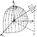
图3为直角坐标系中慢速矢量定义图;Fig. 3 is the slow vector definition diagram in the Cartesian coordinate system;
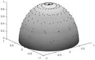
图4为仿真实验的半球形阵列螺旋分布图;Fig. 4 is the hemispherical array spiral distribution figure of simulation experiment;
图5为仿真实验的指向(0°,0°)方向的波束图;Fig. 5 is the beam pattern pointing to (0°, 0°) direction of the simulation experiment;
图6为仿真实验的波束P1、P2、P3、P4图;Fig. 6 is a diagram of beams P1 , P2 , P3 , and P4 in the simulation experiment;
图7为图6的X-Y维视图;Fig. 7 is the X-Y dimensional view of Fig. 6;
图8为图7的局部放大图;Figure 8 is a partially enlarged view of Figure 7;
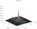
图9为仿真实验的和波束图;Fig. 9 is the sum beam diagram of the simulation experiment;
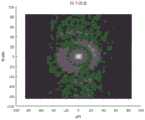
图10为仿真实验的方位向差波束图;Fig. 10 is the azimuth difference beam diagram of the simulation experiment;
图11为仿真实验的俯仰向差波束图;Figure 11 is the pitch difference beam pattern of the simulation experiment;
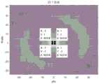
图12为仿真实验的观察窗内方位向差和比图;Fig. 12 is the azimuth difference and ratio diagram in the observation window of the simulation experiment;
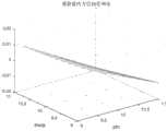
图13为仿真实验的观察窗内方位向差和比X-Z视图;Fig. 13 is the azimuth direction difference and ratio X-Z view in the observation window of the simulation experiment;
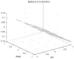
图14为仿真实验的方位向观察窗内鉴角曲线拟合结果图;Fig. 14 is the fitting result figure of the angle-discriminating curve in the azimuth direction observation window of the simulation experiment;
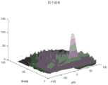
图15为仿真实验的观察窗内俯仰向差和比图;Fig. 15 is the pitch difference and ratio diagram in the observation window of the simulation experiment;
图16为仿真实验的观察窗内俯仰向差和比Y-Z维视图;Fig. 16 is the pitch difference and ratio Y-Z dimension view in the observation window of the simulation experiment;
图17为仿真实验的方位向观察窗内鉴角曲线拟合结果图;Fig. 17 is the fitting result figure of the angle detection curve in the azimuth direction observation window of the simulation experiment;
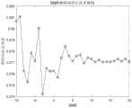
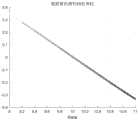
图18为仿真实验的SNR-方位向估计误差曲线图;Fig. 18 is the SNR-azimuth estimation error curve diagram of the simulation experiment;
图19为仿真实验的SNR-俯仰向估计误差曲线图;Fig. 19 is the SNR-pitch estimation error curve diagram of the simulation experiment;
图20为对比实验的常规的阵列坐标系中慢速矢量定义图;Fig. 20 is a slow vector definition diagram in the conventional array coordinate system of the comparative experiment;
图21为对比实验的常规坐标系下的四个波束图的原始视图;Figure 21 is the original view of the four beam patterns under the conventional coordinate system of the comparative experiment;
图22为图21的X-Y视图;Fig. 22 is the X-Y view of Fig. 21;
图23为对比实验的观察窗内方位向差和比的原始视图;Figure 23 is the original view of the azimuth difference and ratio in the observation window of the comparative experiment;
图24为图23的X-Z视图;Fig. 24 is the X-Z view of Fig. 23;
图25为对比实验的观察窗内俯仰向差和比的原始视图;Figure 25 is the original view of the pitch difference and ratio in the observation window of the comparative experiment;
图26为图25的Y-Z视图。Fig. 26 is a Y-Z view of Fig. 25 .
具体实施方式Detailed ways
下面将结合本发明实施例中的附图,对本发明实施例中的技术方案进行清楚、完整地描述,显然,所描述的实施例仅仅是本发明一部分实施例,而不是全部的实施例。基于本发明中的实施例,本领域普通技术人员在没有做出创造性劳动前提下所获得的所有其他实施例,都属于本发明保护的范围。The following will clearly and completely describe the technical solutions in the embodiments of the present invention with reference to the accompanying drawings in the embodiments of the present invention. Obviously, the described embodiments are only some, not all, embodiments of the present invention. Based on the embodiments of the present invention, all other embodiments obtained by persons of ordinary skill in the art without making creative efforts belong to the protection scope of the present invention.
图1所示为本发明实施例提供的一种基于螺旋分布的半球形阵列和差测角解耦合方法的流程示意图。FIG. 1 is a schematic flowchart of a hemispherical array based on a helical distribution and a decoupling method for differential angle measurement provided by an embodiment of the present invention.
如图1所示,本发明实施例提供的基于螺旋分布的半球形阵列和差测角解耦合方法,包括如下步骤:As shown in Figure 1, the hemispherical array based on the helical distribution provided by the embodiment of the present invention and the differential angle decoupling method include the following steps:
步骤1:按照螺旋分布的排列方式将N个阵元分布在一个半径为R的半球面上;Step 1: Distribute N array elements on a hemispherical surface with radius R according to the arrangement of spiral distribution;
N个阵元分布在半球形球面上,整个半球体统称为雷达阵列,即雷达阵列包含N个阵元。N array elements are distributed on a hemispherical surface, and the entire hemisphere is collectively called a radar array, that is, the radar array includes N array elements.
子步骤1a,N个阵元中,其中将第m个阵元在如图2所示坐标系中的位置记为点pm,记qm为点pm在平面XOY的投影点,其中
θm=arccos(hm),


子步骤1b,根据子步骤1a可以得到,第m个阵元在如图所示直角坐标系中的XYZ坐标为:Sub-step 1b, according to sub-step 1a, it can be obtained that the XYZ coordinates of the mth array element in the Cartesian coordinate system shown in the figure are:


zm=R sinθmzm =R sinθm
子步骤1c,根据子步骤1b得到的第m个阵元的阵元坐标,由此可以将N个阵元按照螺旋分布在一个半径为R的半球体上。In sub-step 1c, according to the array element coordinates of the mth array element obtained in sub-step 1b, N array elements can be spirally distributed on a hemisphere with a radius of R.
步骤2:重新定义某方向到来的信号方位角
子步骤2a,假设一来波信号如图3中

子步骤2b,根据慢速矢量的定义,得到慢速矢量为:Sub-step 2b, according to the definition of the slow vector, the slow vector is obtained as:

步骤3:假定目标波束期望方向为


具体包含以下子步骤:It specifically includes the following sub-steps:
子步骤3a,根据半球形阵列波束形成的定义,得到指向

其中,


根据上述定义可以得到P1、P2、P3和P4分别为:According to the above definitions, P1 , P2 , P3 and P4 can be obtained as:


步骤4:计算和波束Psum、俯仰向差波束Pele、方位向差波束Pazi、俯仰向差和比rele和方位向差和比razi;Step 4: Calculate sum beam Psum , pitch difference beam Pele , azimuth difference beam Pazi , pitch difference sum ratio rele and azimuth difference sum ratiorazi ;
具体包含如下子步骤:It specifically includes the following sub-steps:
子步骤4a,根据和波束的定义,得到和波束Psum的计算公式为:In sub-step 4a, according to the definition of the sum beam, the calculation formula of the sum beam Psum is obtained as:
Psum=P1+P2+P3+P4;Psum =P1 +P2 +P3 +P4 ;
子步骤4b,根据俯仰向差波束的定义,得到俯仰向差波束Pele的计算公式为:In sub-step 4b, according to the definition of the pitch difference beam, the calculation formula of the pitch difference beam Pele is obtained as:
Pele=P1+P2-P3-P4;Pele =P1 +P2 -P3 -P4 ;
子步骤4c,根据方位向差波束的定义,得到方位向差波束Pazi的计算公式为:In sub-step 4c, according to the definition of the azimuth difference beam, the calculation formula of the azimuth difference beam Pazi is obtained as:
Pazi=P1-P2+P3-P4;Pazi =P1 -P2 +P3 -P4 ;
子步骤4d,根据俯仰向差和比的定义,得到俯仰向差和比rele的计算公式为:In sub-step 4d, according to the definition of the pitch difference and ratio, the calculation formula of the pitch difference and ratio rele is:

子步骤4e,根据方位向差和比的定义,得到方位向差和比razi的计算公式为:In sub-step 4e, according to the definition of the azimuth difference and ratio, the formula for calculating the azimuth difference and ratio razi is:

由此得到和波束Psum、俯仰向差波束Pele、方位向差波束Pazi、俯仰向差和比rele和方位向差和比razi。Thus, the sum beam Psum , the elevation difference beam Pele , the azimuth difference beam Pazi , the elevation difference sum ratio rele , and the azimuth difference sum ratiorazi are obtained.
步骤5:设置方位向观察窗

具体的,设置1-2°的方位向观察窗


以下通过仿真实验对本发明实施例提供的上述方法的效果进行验证:The effect of the above-mentioned method provided by the embodiment of the present invention is verified by simulation experiments as follows:
1.仿真实验环境和数据:1. Simulation experiment environment and data:
实验环境:Inter(R)Core(TM)i5-6500 CPU@3.20HGz,64位Windows操作系统和MATLAB 2016b仿真软件。Experimental environment: Inter(R) Core(TM) i5-6500 CPU@3.20HGz, 64-bit Windows operating system and MATLAB 2016b simulation software.
实验参数:雷达阵列的阵元总个数N为200个,方位角


2.仿真实验结果:2. Simulation results:
由步骤1得到的半球形阵列螺旋分布如图4所示;The spiral distribution of the hemispherical array obtained in
根据步骤3可以得到指向目标方位(0°,0°)的波束如图5所示;According to step 3, the beam pointing to the target azimuth (0°, 0°) can be obtained as shown in Figure 5;
波束P1、P2、P3和P4如图6所示,图7为图6的X-Y维视图,图8为图7的局部放大图。从图8中可以看出,四个波束分别指向(-1°,-1°)、(-1°,1°)、(1°,-1°)和(1°,1°)。Beams P1 , P2 , P3 and P4 are shown in FIG. 6 , FIG. 7 is an XY-dimensional view of FIG. 6 , and FIG. 8 is a partially enlarged view of FIG. 7 . It can be seen from Figure 8 that the four beams point to (-1°, -1°), (-1°, 1°), (1°, -1°) and (1°, 1°) respectively.
从图9中可以看出,和波束指向(0°,0°)。由图10和图11可以得到,方位向差波束和俯仰向差波束在(0°,0°)点旁边分别存在一个波峰和一个波谷,所不同的是,方位向差波束(0°,0°)旁的波峰和波谷是在
从图12和图13可以得到,观察窗内方位向差和比只与方位角


从图15和图16可以得到,观察窗内俯仰向差和比只与俯仰角θ有关,与方位角
在图14和图17所示的鉴角曲线的基础上,对其进行和差测角和误差分析,可以得到误差-SNR曲线如图18和图19所示。On the basis of the angle detection curves shown in Figure 14 and Figure 17, the sum and difference angle measurement and error analysis can be performed on it, and the error-SNR curve can be obtained as shown in Figure 18 and Figure 19.
由图18和图19可知,在图14和图17所获得鉴角曲线的基础上,用半球形螺旋分布的阵列对其进行和差测角,得到的误差大概在0.07左右,误差处于一个比较小的范围,并且信噪比SNR对误差的影响不是很大,这主要是因为和波束和差波束在做比值前,信号对其进行积累导致的。It can be seen from Figure 18 and Figure 19 that, on the basis of the angle discrimination curves obtained in Figure 14 and Figure 17, the array of hemispherical spiral distribution is used to measure the sum and difference of the angle, and the error obtained is about 0.07, which is in a comparison The range is small, and the signal-to-noise ratio SNR does not have a great influence on the error, which is mainly caused by the signal accumulation before the sum beam and the difference beam are compared.
由图18和图19所示,设置的方位向和俯仰向的观察窗大小分别为2°,因为方位向和俯仰向已经解耦合,因此需要预存储的直线数据为180条直线;但是如果没有解耦合,那么需要预存储的数据量大约为上千个平面,而且每个平面假设都由几百条直线组成,那么需要存储的直线大约为105条。As shown in Figure 18 and Figure 19, the size of the observation window in the azimuth direction and the pitch direction is set to 2° respectively, because the azimuth direction and the pitch direction have been decoupled, so the straight line data that needs to be pre-stored is 180 straight lines; but if there is no Decoupling, the amount of data that needs to be pre-stored is about thousands of planes, and each plane is assumed to be composed of hundreds of straight lines, then the number of straight lines that need to be stored is about 105 .
3.对比实验结果:3. Compare the experimental results:
常规的阵列坐标系定义,如图20所示,图中p为空间一电磁波向量,q为p在XOY平面的投影,其中

假定球面半径R=10λ,中心波束的指向的角度为(10°,10°),那么分别合成指向(11°,9°)、(9°,11°)、(9°,9°)和(11°,11°)四个方向的波束,四个波束如图21和图22所示:Assuming that the radius of the sphere is R=10λ, and the pointing angle of the center beam is (10°, 10°), then the synthetic points are (11°, 9°), (9°, 11°), (9°, 9°) and (11°, 11°) beams in four directions, the four beams are shown in Figure 21 and Figure 22:
图21为常规坐标系下的四个波束图的原始视图,图22为图21的X-Y视图;可以看出:图中只有俯仰向的两个波束。这是因为波束在方位向上比较宽,但是其指向的角度却相差很小,所以方位向的两个波束重合到在一起,因此,在图中只能看到俯仰向的两个波束。综上所述,可以得出结论:在常规坐标系下,螺旋分布的四个波束图在俯仰向上完全不对称。Figure 21 is the original view of the four beam patterns in the conventional coordinate system, and Figure 22 is the X-Y view of Figure 21; it can be seen that there are only two beams in the elevation direction in the figure. This is because the beam is relatively wide in azimuth, but the difference in pointing angle is very small, so the two beams in azimuth overlap together, so only the two beams in elevation can be seen in the figure. In summary, it can be concluded that in the conventional coordinate system, the four beam patterns of the helical distribution are completely asymmetrical in the pitch direction.
假设方位向观察窗
由上述仿真实验和对比实验结果可知,本发明的方法在坐标重新定义和取近似的基础上,有效的在部分范围内解决了半球形阵列螺旋分布和差测角时存在的方位向和俯仰向耦合的问题,大大减少了和差测角需要预存储的数据量,并且使得和差测角的误差处于一个比较小的范围。It can be seen from the results of the above-mentioned simulation experiments and comparative experiments that the method of the present invention effectively solves the azimuth and pitch directions that exist in the hemispherical array helical distribution and differential angle measurement on the basis of coordinate redefinition and approximation. The problem of coupling greatly reduces the amount of data that needs to be pre-stored in the sum and difference angle measurement, and makes the error of the sum and difference angle measurement in a relatively small range.
本领域普通技术人员可以理解:实现上述方法实施例的全部或部分步骤可以通过程序指令相关的硬件来完成,前述的程序可以存储于计算机可读取存储介质中,该程序在执行时,执行包括上述方法实施例的步骤;而前述的存储介质包括:ROM、RAM、磁碟或者光盘等各种可以存储程序代码的介质。Those of ordinary skill in the art can understand that all or part of the steps to realize the above method embodiments can be completed by hardware related to program instructions, and the aforementioned programs can be stored in computer-readable storage media. When the program is executed, the execution includes The steps of the above-mentioned method embodiments; and the aforementioned storage medium includes: ROM, RAM, magnetic disk or optical disk and other various media that can store program codes.
以上所述,仅为本发明的具体实施方式,但本发明的保护范围并不局限于此,任何熟悉本技术领域的技术人员在本发明揭露的技术范围内,可轻易想到变化或替换,都应涵盖在本发明的保护范围之内。因此,本发明的保护范围应以所述权利要求的保护范围为准。The above is only a specific embodiment of the present invention, but the scope of protection of the present invention is not limited thereto. Anyone skilled in the art can easily think of changes or substitutions within the technical scope disclosed in the present invention. Should be covered within the protection scope of the present invention. Therefore, the protection scope of the present invention should be determined by the protection scope of the claims.
Claims (6)
Translated fromChinese


Priority Applications (1)
| Application Number | Priority Date | Filing Date | Title |
|---|---|---|---|
| CN201910199805.6ACN109901146B (en) | 2019-03-15 | 2019-03-15 | Hemispherical array and differential angle decoupling method based on spiral distribution |
Applications Claiming Priority (1)
| Application Number | Priority Date | Filing Date | Title |
|---|---|---|---|
| CN201910199805.6ACN109901146B (en) | 2019-03-15 | 2019-03-15 | Hemispherical array and differential angle decoupling method based on spiral distribution |
Publications (2)
| Publication Number | Publication Date |
|---|---|
| CN109901146A CN109901146A (en) | 2019-06-18 |
| CN109901146Btrue CN109901146B (en) | 2023-03-14 |
Family
ID=66952666
Family Applications (1)
| Application Number | Title | Priority Date | Filing Date |
|---|---|---|---|
| CN201910199805.6AActiveCN109901146B (en) | 2019-03-15 | 2019-03-15 | Hemispherical array and differential angle decoupling method based on spiral distribution |
Country Status (1)
| Country | Link |
|---|---|
| CN (1) | CN109901146B (en) |
Families Citing this family (1)
| Publication number | Priority date | Publication date | Assignee | Title |
|---|---|---|---|---|
| CN116295451A (en)* | 2023-03-20 | 2023-06-23 | 北京理工大学 | Optical navigation pose decoupling estimation method for deep space detector |
Citations (6)
| Publication number | Priority date | Publication date | Assignee | Title |
|---|---|---|---|---|
| GB208087A (en)* | 1923-05-28 | 1923-12-13 | Francis Joseph Stawell Jones | Improvements in and connected with internal combustion engine fuel tanks having automatically controlled feeds |
| US5130714A (en)* | 1991-05-23 | 1992-07-14 | Hughes Aircraft Company | Stretch and chirp waveform format for reduced generating and receiving hardware complexity |
| CN202091337U (en)* | 2011-04-21 | 2011-12-28 | 江苏南方轴承股份有限公司 | Decoupling appliance core shaft capable of preventing force transmission interference and decoupling appliance of same |
| WO2012099704A2 (en)* | 2011-01-17 | 2012-07-26 | Novita Therapeutics, Llc | Blockstent device and methods of use |
| CN103035994A (en)* | 2011-08-22 | 2013-04-10 | 英飞凌科技股份有限公司 | Microstrip coupler combining transmit-receive signal separation and differential to single ended conversion |
| CN103235292A (en)* | 2013-05-08 | 2013-08-07 | 西安电子科技大学 | Full-dimension and difference angle measurement method for zero setting conformal calibration of a planar phased array |
- 2019
- 2019-03-15CNCN201910199805.6Apatent/CN109901146B/enactiveActive
Patent Citations (6)
| Publication number | Priority date | Publication date | Assignee | Title |
|---|---|---|---|---|
| GB208087A (en)* | 1923-05-28 | 1923-12-13 | Francis Joseph Stawell Jones | Improvements in and connected with internal combustion engine fuel tanks having automatically controlled feeds |
| US5130714A (en)* | 1991-05-23 | 1992-07-14 | Hughes Aircraft Company | Stretch and chirp waveform format for reduced generating and receiving hardware complexity |
| WO2012099704A2 (en)* | 2011-01-17 | 2012-07-26 | Novita Therapeutics, Llc | Blockstent device and methods of use |
| CN202091337U (en)* | 2011-04-21 | 2011-12-28 | 江苏南方轴承股份有限公司 | Decoupling appliance core shaft capable of preventing force transmission interference and decoupling appliance of same |
| CN103035994A (en)* | 2011-08-22 | 2013-04-10 | 英飞凌科技股份有限公司 | Microstrip coupler combining transmit-receive signal separation and differential to single ended conversion |
| CN103235292A (en)* | 2013-05-08 | 2013-08-07 | 西安电子科技大学 | Full-dimension and difference angle measurement method for zero setting conformal calibration of a planar phased array |
Non-Patent Citations (2)
| Title |
|---|
| Measuring Leaf Angle Distribution Using Terrestrial Laser Scanning in a European Beech Forest;Jing Liu et al.;《IGARSS 2018》;20180727;第8977-8980页* |
| 矢量推进解耦球面并联机构动力学研究;张荣敏 等;《农业机械学报》;20150616;第46卷(第6期);第319-325页* |
Also Published As
| Publication number | Publication date |
|---|---|
| CN109901146A (en) | 2019-06-18 |
Similar Documents
| Publication | Publication Date | Title |
|---|---|---|
| CN106772260B (en) | Radar array and difference beam directional diagram optimization method based on convex optimized algorithm | |
| CN103383450B (en) | Conformal array radar amplitude-phase error correction fast achieving method | |
| CN105445718B (en) | A DOA Estimation Method for Distributed Multi-carrier Over-the-Horizon Radar Based on Array Reconfiguration | |
| CN103235292B (en) | Full-dimension and difference angle measurement method for zero setting conformal calibration of a planar phased array | |
| CN110161452B (en) | Direction-of-arrival estimation method based on cross-prime L-shaped electromagnetic vector sensor array | |
| CN103020363B (en) | A kind of method by improving array beams directional diagram sidelobe performance designing antenna | |
| CN113671485B (en) | ADMM-based two-dimensional DOA estimation method for meter wave area array radar | |
| CN108549059A (en) | A kind of low target elevation estimate method under MODEL OVER COMPLEX TOPOGRAPHY | |
| CN112612010A (en) | Meter-wave radar low elevation height measurement method based on lobe splitting pretreatment | |
| CN112596022B (en) | Wave arrival angle estimation method of low-orbit satellite-borne multi-beam regular hexagonal phased array antenna | |
| CN102195701A (en) | Method for suppressing side lobes of sum beams and difference beams of planar phased array only by utilizing one kind of analogue weighting | |
| CN109901146B (en) | Hemispherical array and differential angle decoupling method based on spiral distribution | |
| CN112014835B (en) | Target tracking method and device of distributed sparse array radar under grating lobe ambiguity | |
| CN113820654B (en) | S-band radar target low elevation DOA estimation method based on beam domain dimension reduction | |
| CN109901131B (en) | Multipath utilization coherent beam forming method based on oblique projection | |
| CN111323742A (en) | Phase interferometer based on curve array and direction finding method thereof | |
| CN118777975B (en) | Polarization sensitive array direction finding method based on antenna airspace polarization characteristics | |
| CN118962686A (en) | A multipath identification and target distance estimation method for deep-sea horizontal line arrays | |
| CN102121981A (en) | Method for restricting static directional pattern sidelobe based on subarray-level digital weighting | |
| CN105242264B (en) | A kind of planar array multiple target angle high-resolution implementation method | |
| CN111735996A (en) | A method and device for suppressing multipath interference for the construction of a mathematical anechoic chamber | |
| CN118376982A (en) | Anti-interference method based on sample segmented differential array | |
| CN113406620B (en) | Distributed array angle measurement method for array decomposition | |
| CN112285641B (en) | ICA-based DOA (direction of arrival) estimation method and device | |
| CN104199005B (en) | The distributed meter wave array radar optimum length of base determines method |
Legal Events
| Date | Code | Title | Description |
|---|---|---|---|
| PB01 | Publication | ||
| PB01 | Publication | ||
| SE01 | Entry into force of request for substantive examination | ||
| SE01 | Entry into force of request for substantive examination | ||
| GR01 | Patent grant | ||
| GR01 | Patent grant |