CN109891096B - liquid pump - Google Patents
liquid pumpDownload PDFInfo
- Publication number
- CN109891096B CN109891096BCN201780066330.2ACN201780066330ACN109891096BCN 109891096 BCN109891096 BCN 109891096BCN 201780066330 ACN201780066330 ACN 201780066330ACN 109891096 BCN109891096 BCN 109891096B
- Authority
- CN
- China
- Prior art keywords
- discharge
- suction
- side tank
- pump chamber
- liquid
- Prior art date
- Legal status (The legal status is an assumption and is not a legal conclusion. Google has not performed a legal analysis and makes no representation as to the accuracy of the status listed.)
- Active
Links
Images


Classifications
- F—MECHANICAL ENGINEERING; LIGHTING; HEATING; WEAPONS; BLASTING
- F04—POSITIVE - DISPLACEMENT MACHINES FOR LIQUIDS; PUMPS FOR LIQUIDS OR ELASTIC FLUIDS
- F04B—POSITIVE-DISPLACEMENT MACHINES FOR LIQUIDS; PUMPS
- F04B43/00—Machines, pumps, or pumping installations having flexible working members
- F04B43/02—Machines, pumps, or pumping installations having flexible working members having plate-like flexible members, e.g. diaphragms
- F04B43/04—Pumps having electric drive
- F04B43/043—Micropumps
- F—MECHANICAL ENGINEERING; LIGHTING; HEATING; WEAPONS; BLASTING
- F04—POSITIVE - DISPLACEMENT MACHINES FOR LIQUIDS; PUMPS FOR LIQUIDS OR ELASTIC FLUIDS
- F04B—POSITIVE-DISPLACEMENT MACHINES FOR LIQUIDS; PUMPS
- F04B43/00—Machines, pumps, or pumping installations having flexible working members
- F04B43/0009—Special features
- F—MECHANICAL ENGINEERING; LIGHTING; HEATING; WEAPONS; BLASTING
- F04—POSITIVE - DISPLACEMENT MACHINES FOR LIQUIDS; PUMPS FOR LIQUIDS OR ELASTIC FLUIDS
- F04B—POSITIVE-DISPLACEMENT MACHINES FOR LIQUIDS; PUMPS
- F04B43/00—Machines, pumps, or pumping installations having flexible working members
- F04B43/02—Machines, pumps, or pumping installations having flexible working members having plate-like flexible members, e.g. diaphragms
- F04B43/04—Pumps having electric drive
- F04B43/043—Micropumps
- F04B43/046—Micropumps with piezoelectric drive
- F—MECHANICAL ENGINEERING; LIGHTING; HEATING; WEAPONS; BLASTING
- F04—POSITIVE - DISPLACEMENT MACHINES FOR LIQUIDS; PUMPS FOR LIQUIDS OR ELASTIC FLUIDS
- F04B—POSITIVE-DISPLACEMENT MACHINES FOR LIQUIDS; PUMPS
- F04B53/00—Component parts, details or accessories not provided for in, or of interest apart from, groups F04B1/00 - F04B23/00 or F04B39/00 - F04B47/00
- F04B53/10—Valves; Arrangement of valves
- F04B53/1037—Flap valves
- F04B53/1047—Flap valves the valve being formed by one or more flexible elements
- F04B53/106—Flap valves the valve being formed by one or more flexible elements the valve being a membrane
- F04B53/1065—Flap valves the valve being formed by one or more flexible elements the valve being a membrane fixed at its centre
- F—MECHANICAL ENGINEERING; LIGHTING; HEATING; WEAPONS; BLASTING
- F04—POSITIVE - DISPLACEMENT MACHINES FOR LIQUIDS; PUMPS FOR LIQUIDS OR ELASTIC FLUIDS
- F04B—POSITIVE-DISPLACEMENT MACHINES FOR LIQUIDS; PUMPS
- F04B53/00—Component parts, details or accessories not provided for in, or of interest apart from, groups F04B1/00 - F04B23/00 or F04B39/00 - F04B47/00
- F04B53/16—Casings; Cylinders; Cylinder liners or heads; Fluid connections
- F—MECHANICAL ENGINEERING; LIGHTING; HEATING; WEAPONS; BLASTING
- F05—INDEXING SCHEMES RELATING TO ENGINES OR PUMPS IN VARIOUS SUBCLASSES OF CLASSES F01-F04
- F05B—INDEXING SCHEME RELATING TO WIND, SPRING, WEIGHT, INERTIA OR LIKE MOTORS, TO MACHINES OR ENGINES FOR LIQUIDS COVERED BY SUBCLASSES F03B, F03D AND F03G
- F05B2210/00—Working fluid
- F05B2210/10—Kind or type
- F05B2210/11—Kind or type liquid, i.e. incompressible
- F—MECHANICAL ENGINEERING; LIGHTING; HEATING; WEAPONS; BLASTING
- F05—INDEXING SCHEMES RELATING TO ENGINES OR PUMPS IN VARIOUS SUBCLASSES OF CLASSES F01-F04
- F05B—INDEXING SCHEME RELATING TO WIND, SPRING, WEIGHT, INERTIA OR LIKE MOTORS, TO MACHINES OR ENGINES FOR LIQUIDS COVERED BY SUBCLASSES F03B, F03D AND F03G
- F05B2260/00—Function
- F05B2260/60—Fluid transfer
- Y—GENERAL TAGGING OF NEW TECHNOLOGICAL DEVELOPMENTS; GENERAL TAGGING OF CROSS-SECTIONAL TECHNOLOGIES SPANNING OVER SEVERAL SECTIONS OF THE IPC; TECHNICAL SUBJECTS COVERED BY FORMER USPC CROSS-REFERENCE ART COLLECTIONS [XRACs] AND DIGESTS
- Y10—TECHNICAL SUBJECTS COVERED BY FORMER USPC
- Y10S—TECHNICAL SUBJECTS COVERED BY FORMER USPC CROSS-REFERENCE ART COLLECTIONS [XRACs] AND DIGESTS
- Y10S417/00—Pumps
Landscapes
- Engineering & Computer Science (AREA)
- Mechanical Engineering (AREA)
- General Engineering & Computer Science (AREA)
- Reciprocating Pumps (AREA)
Abstract
Description
Translated fromChinese技术领域technical field
本发明涉及一种通过使泵室的容积周期性膨胀收缩而将液体从吸引口吸引并从排出口排出的液体泵。The present invention relates to a liquid pump that sucks liquid from a suction port and discharges it from a discharge port by periodically expanding and contracting the volume of a pump chamber.
背景技术Background technique
在用于输送水、药品等液体的液体泵中,存在如下液体泵:通过使划分出泵室的壁的一部分以使泵室的容积变动的方式进行振动,从而将液体从吸引口吸引并从排出口排出。例如,在专利文献1中,公开了如下液体泵:将粘合有两片压电元件而得到的层叠型的膜状振子(双层压电振子)作为泵室的壁的一部分而配置,通过对该膜状振子施加交流电压来使该振子振动,从而使泵室的容积膨胀收缩而对液体进行输送。在该液体泵中,在吸引液体的吸引口与泵室之间、以及在排出液体的排出口与泵室之间分别配置单向阀,在泵室膨胀了时将液体从吸引口经由吸引口侧的单向阀而向泵室内吸引,在泵室收缩了时将泵室内的液体经由排出口侧的单向阀而从排出口排出。Among the liquid pumps for conveying liquids such as water and chemicals, there is a liquid pump in which a part of a wall defining a pump chamber vibrates so as to change the volume of the pump chamber, thereby sucking the liquid from a suction port and removing the liquid from the suction port. The discharge port is discharged. For example, Patent Document 1 discloses a liquid pump in which a laminated film vibrator (two-layer piezoelectric vibrator) obtained by bonding two piezoelectric elements is arranged as a part of the wall of the pump chamber, An alternating voltage is applied to the membrane vibrator to vibrate the vibrator, thereby expanding and contracting the volume of the pump chamber to transport the liquid. In this liquid pump, check valves are respectively disposed between a suction port for sucking liquid and the pump chamber, and between a discharge port for discharging liquid and the pump chamber, and when the pump chamber is inflated, the liquid is passed from the suction port through the suction port. The check valve on the side is sucked into the pump chamber, and when the pump chamber contracts, the liquid in the pump chamber is discharged from the discharge port through the check valve on the discharge port side.
在上述那样的液体泵中,在从泵室排出液体时泵室收缩而泵室内被加压,由此从泵室内朝向排出口送出液体,但在排出口侧的流体阻力较大时则无法从泵室送出足够量的液体。另外,在向泵室内吸引液体时,也发生同样的现象,在吸引口侧的流体阻力较大时无法向泵室内吸引足够量的液体。即,由于排出口以及吸引口中的流体阻力的增加而导致泵的性能降低。作为上述那样的问题的解决手段而进行有如下设置:在吸引口侧以及排出口侧设置贮存罐,并在该罐内形成空气存积部(专利文献2)。通过设置上述那样的形成有空气存积部的罐,从而在吸引液体时,吸引口侧的罐内的空气暂时膨胀,由此流体从吸引侧的罐被向泵室内吸引时的阻力变小。另外,在排出液体时,排出口侧的罐内的空气暂时收缩,从而将流体从泵室向排出侧的罐内送出时的阻力变小。由此,即便吸引口以及排出口中的流体阻力变大,也能够由此抑制泵的性能降低。In the above-described liquid pump, when the liquid is discharged from the pump chamber, the pump chamber contracts and the pump chamber is pressurized, whereby the liquid is sent from the pump chamber toward the discharge port. The pump chamber delivers a sufficient amount of liquid. In addition, the same phenomenon occurs when the liquid is sucked into the pump chamber, and when the fluid resistance on the suction port side is large, a sufficient amount of the liquid cannot be sucked into the pump chamber. That is, the performance of the pump decreases due to the increase in the fluid resistance in the discharge port and the suction port. As a solution to the above-mentioned problems, there is provided a storage tank on the suction port side and the discharge port side, and an air storage portion is formed in the tank (Patent Document 2). By providing the tank with the air reservoir as described above, the air in the tank on the suction port side expands temporarily when the liquid is sucked, thereby reducing the resistance when the fluid is sucked from the tank on the suction side into the pump chamber. In addition, when the liquid is discharged, the air in the tank on the discharge port side contracts temporarily, and the resistance when the fluid is sent out from the pump chamber into the tank on the discharge side becomes small. Thereby, even if the fluid resistance in the suction port and the discharge port increases, the performance of the pump can be suppressed from deteriorating.
在先技术文献prior art literature
专利文献Patent Literature
专利文献1:日本实开平2-94382号公报Patent Document 1: Japanese Patent Application Laid-Open No. 2-94382
专利文献2:日本特开昭62-214287号公报Patent Document 2: Japanese Patent Laid-Open No. 62-214287
发明内容SUMMARY OF THE INVENTION
发明要解决的课题The problem to be solved by the invention
上述那样的液体泵通常能够通过使振子的振动频率变化来改变液体的排出量。然而,若为了增大排出量而使振动频率变大,则尤其在排出侧的罐内,有时由于在液体中传递的振动而导致在罐内的液面附近产生包含空气存积部的空气的气泡,导致呈泡状的空气向液体内扩散并与液体一起从排出口排出。于是,产生如下问题:空气存积部逐渐变少而减轻流体阻力的影响的效果减少,其结果是,无法维持泵的排出性能。In the above-mentioned liquid pump, the discharge amount of the liquid can usually be changed by changing the vibration frequency of the vibrator. However, if the vibration frequency is increased in order to increase the discharge amount, especially in the tank on the discharge side, vibrations transmitted through the liquid may cause air including the air reservoir in the tank near the liquid level. Air bubbles, causing the air in the form of bubbles to diffuse into the liquid and be discharged from the discharge port together with the liquid. Then, there arises a problem that the air reservoir gradually decreases and the effect of reducing the influence of the fluid resistance decreases, and as a result, the discharge performance of the pump cannot be maintained.
为此,本发明的目的在于,提供一种抑制形成于排出侧罐内的空气存积部的空气被排出的液体泵。Therefore, an object of the present invention is to provide a liquid pump that suppresses discharge of the air formed in the air reservoir in the discharge-side tank.
用于解决课题的手段means of solving problems
即本发明的目的在于,提供一种液体泵,其具备:That is, the object of the present invention is to provide a liquid pump, which has:
吸引口,其吸引液体;suction port, which attracts liquid;
泵室,其与所述吸引口连通,划分出所述泵室的壁的一部分是能够振动以使得所述泵室的容积变动的振动壁部;a pump chamber, which communicates with the suction port, and a part of the wall that defines the pump chamber is a vibrating wall portion that can vibrate to change the volume of the pump chamber;
排出侧连通路径,其从所述泵室延伸;a discharge-side communication path extending from the pump chamber;
排出侧罐部,其经由所述排出侧连通路径与所述泵室连通,用于贮存从所述泵室送出的液体;a discharge-side tank portion, which communicates with the pump chamber via the discharge-side communication path, and stores the liquid sent from the pump chamber;
排出侧单向阀,其以从所述泵室朝向所述排出侧罐部的流体通过而从所述排出侧罐部朝向所述泵室的流体不通过的方式配置于所述排出侧罐部与所述泵室之间;以及A discharge-side check valve disposed in the discharge-side tank portion so that fluid from the pump chamber toward the discharge-side tank portion passes and fluid from the discharge-side tank portion toward the pump chamber does not pass through and the pump chamber; and
排出口,其排出所述排出侧罐部内的液体,a discharge port, which discharges the liquid in the tank portion on the discharge side,
所述液体泵设为,随着所述振动壁部的振动,将液体从所述吸引口吸引并从所述排出口排出,The liquid pump is configured to suck the liquid from the suction port and discharge the liquid from the discharge port in accordance with the vibration of the vibrating wall portion,
所述排出侧罐部具有在所述液体泵的设置状态下的水平方向上彼此对置的第一内侧面以及第二内侧面,在所述第一内侧面形成有所述排出口,在所述第二内侧面形成有所述排出侧连通路径的开口部,在所述排出侧罐部内的比所述排出侧连通路径的开口部以及所述排出口靠上侧的空间形成空气存积部,The discharge-side tank portion has a first inner side surface and a second inner side surface facing each other in the horizontal direction in the installation state of the liquid pump, the discharge port is formed on the first inner side surface, and the discharge port is formed on the first inner side surface. An opening of the discharge-side communication path is formed on the second inner surface, and an air storage portion is formed in a space above the opening of the discharge-side communication path and the discharge port in the discharge-side tank portion. ,
在所述排出侧罐部内,在所述排出侧连通路径的开口部的至少上侧位置还具有隔壁部,所述隔壁部以从所述空气存积部侧观察时覆盖所述开口部的方式从所述第二内侧面朝向所述第一内侧面突出。In the discharge-side tank portion, a partition wall portion is further provided at least at an upper position of the opening portion of the discharge-side communication path, and the partition wall portion covers the opening portion when viewed from the air storage portion side. It protrudes from the second inner side toward the first inner side.
在该液体泵中,在排出侧罐部内,在排出侧连通路径的开口部与空气存积部之间设有隔壁部,因此,即便在排出侧罐部内的液面附近产生了包含空气存积部的空气的气泡,该空气也难以向下方扩散。由此,能够抑制空气从排出口排出。In this liquid pump, in the discharge-side tank portion, the partition portion is provided between the opening portion of the discharge-side communication path and the air storage portion, so even if air-containing storage occurs in the vicinity of the liquid surface in the discharge-side tank portion The air bubbles in the upper part are also difficult to diffuse downward. Thereby, air can be suppressed from being discharged from the discharge port.
具体而言,可以的是,在所述隔壁部与所述第一内侧面之间隔开有间隔。Specifically, a gap may be provided between the partition wall portion and the first inner side surface.
更具体而言,可以的是,所述隔壁部是以将所述排出侧连通路径的所述开口部的周围包围的方式从所述第二内侧面突出的筒状隔壁部。More specifically, the partition part may be a cylindrical partition part protruding from the second inner surface so as to surround the periphery of the opening of the discharge-side communication path.
优选为,可以的是,所述排出侧连通路径的开口部和所述排出口配置于比所述排出侧罐部的上下方向上的中心位置靠下方的位置。Preferably, the opening of the discharge-side communication path and the discharge port may be arranged at a position lower than a center position in the vertical direction of the discharge-side tank portion.
由此,比排出侧罐部内的排出口以及排出侧连通路径靠上侧的空间变得更大,能够使空气存积部变得更大。另外,使空气存积部与排出口之间的距离变大,从而更可靠地抑制空气从排出口排出。Thereby, the space on the upper side of the discharge port and the discharge-side communication path in the discharge-side tank portion becomes larger, and the air storage portion can be made larger. In addition, by increasing the distance between the air storage portion and the discharge port, the discharge of air from the discharge port can be suppressed more reliably.
更具体而言,可以的是,More specifically, it is possible to,
所述液体泵还具备包括第一壳体部、第二壳体部以及第三壳体部的壳体,所述第一壳体部、所述第二壳体部以及所述第三壳体部分别整体上呈板状,所述壳体通过在由所述第一壳体部和所述第三壳体部夹着所述第二壳体部的状态下使所述第一壳体部、所述第二壳体部以及所述第三壳体部彼此重合而形成,The liquid pump further includes a housing including a first housing portion, a second housing portion, and a third housing portion, the first housing portion, the second housing portion, and the third housing Each of the first and third case parts is formed into a plate shape as a whole, and the first case part is formed by making the first case part and the third case part sandwich the second case part. , the second housing portion and the third housing portion are formed by overlapping each other,
所述第一壳体部具有所述吸引口和所述排出口,还具有以所述第一内侧面作为底面并朝向所述第二壳体部开口的第一排出侧罐凹部,The first case part has the suction port and the discharge port, and further has a first discharge-side tank concave part opened toward the second case part with the first inner side as a bottom surface,
所述第二壳体部具有:第二排出侧罐凹部,其以所述第二内侧面作为底面并朝向所述第一壳体部开口;以及泵室凹部,其在所述第二排出侧罐凹部的相反侧朝向所述第三壳体部开口,The second housing portion has: a second discharge-side tank recess that has the second inner side as a bottom surface and opens toward the first housing portion; and a pump chamber recess that is on the second discharge side The opposite side of the tank recess is open toward the third housing portion,
所述振动壁部是设为夹持于所述第二壳体部与所述第三壳体部之间并覆盖所述泵室凹部的开口的部分的膜状振子,The vibrating wall portion is a film-shaped vibrator that is sandwiched between the second case portion and the third case portion and covers the portion of the opening of the pump chamber concave portion,
所述排出侧罐部由所述第一排出侧罐凹部和所述第二排出侧罐凹部构成。The discharge-side tank portion is constituted by the first discharge-side tank recessed portion and the second discharge-side tank recessed portion.
优选为,可以的是,Preferably, it is possible,
所述液体泵还具备:The liquid pump also has:
吸引侧罐部,其配置于所述吸引口与所述泵室之间,用于贮存从所述吸引口吸引来的液体;a suction side tank part, which is arranged between the suction port and the pump chamber and stores the liquid sucked from the suction port;
吸引侧连通路径,其将所述吸引侧罐部与所述泵室连通;以及a suction-side communication path that communicates the suction-side tank portion with the pump chamber; and
吸引侧单向阀,其配置为从所述泵室侧覆盖所述吸引侧连通路径的所述泵室侧的开口部,并设为使得从所述吸引侧罐部朝向所述泵室的流体通过而从所述泵室朝向所述吸引侧罐部的流体不通过,A suction-side check valve, which is arranged so as to cover an opening on the pump chamber side of the suction-side communication path from the pump chamber side, and is arranged so that the fluid flowing from the suction-side tank portion is directed toward the pump chamber. The fluid passing from the pump chamber toward the suction side tank portion does not pass through,
所述吸引侧罐部具有在所述液体泵的设置状态下的水平方向上彼此对置的第一内侧面以及第二内侧面,在所述吸引侧罐的所述第一内侧面形成有所述吸引口,在所述吸引侧罐的所述第二内侧面形成有所述吸引侧连通路径的所述吸引侧罐部侧的开口部,在所述吸引侧罐部内的比所述开口部以及所述吸引口靠上侧的空间形成空气存积部,The suction-side tank portion has a first inner side surface and a second inner side surface that face each other in a horizontal direction in a state where the liquid pump is installed, and is formed on the first inner side surface of the suction-side tank. In the suction port, an opening on the suction side tank portion side of the suction side communication path is formed on the second inner surface of the suction side tank, and the opening portion in the suction side tank portion is smaller than the opening portion. And the space on the upper side of the suction port forms an air storage part,
在所述吸引侧罐部内,在所述吸引侧罐侧的所述开口部的至少上侧位置,还具有以从所述空气存积部侧观察时覆盖所述吸引侧罐侧的所述开口部的方式从所述吸引侧罐的所述第二内侧面朝向所述吸引侧罐的所述第一内侧面突出的隔壁部。The suction side tank portion further includes the opening that covers the suction side tank side when viewed from the air reservoir side at least at an upper position of the opening portion on the suction side tank side. A partition portion protruding from the second inner side surface of the suction side tank toward the first inner side surface of the suction side tank in a manner of a part.
通过设置吸引侧罐,还能够使该液体泵的吸引能力稳定。另外,通过在吸引侧罐内也设置隔壁部,从而能够防止吸引侧罐内的空气被向泵室侧吸引。By providing the suction side tank, the suction capability of the liquid pump can also be stabilized. In addition, by providing the partition part in the suction side tank as well, it is possible to prevent the air in the suction side tank from being sucked to the pump chamber side.
附图说明Description of drawings
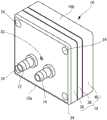
图1是本发明的一实施方式的液体泵的立体图。FIG. 1 is a perspective view of a liquid pump according to an embodiment of the present invention.
图2是图1的液体泵的主视图。FIG. 2 is a front view of the liquid pump of FIG. 1 .
图3是沿着图2的III-III线的剖视图。FIG. 3 is a cross-sectional view taken along line III-III of FIG. 2 .
图4是沿着图2的IV-IV线的剖视图。FIG. 4 is a cross-sectional view taken along line IV-IV of FIG. 2 .
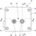
图5是图1的液体泵中的第二壳体的主视图。FIG. 5 is a front view of a second housing in the liquid pump of FIG. 1 .
具体实施方式Detailed ways
以下,基于附图对本发明的液体泵的实施方式进行说明。Hereinafter, embodiments of the liquid pump of the present invention will be described based on the drawings.
如图1以及图2所示,本发明的一实施方式的液体泵10具备壳体16,该壳体16具有:吸引嘴12,其用于安装吸引侧的管(未图示);以及排出嘴14,其用于安装排出侧的管(未图示)。如图3所示,在该壳体16内配置有具有两片压电元件的膜状振子18,通过如后述那样对压电元件施加交流电压而使膜状振子18周期性振动,从而将液体从吸引嘴12的吸引口20吸引并从排出嘴14的排出口22排出。该液体泵10通过插入形成于壳体16的4个螺钉安装孔24的螺钉(未图示)而安装于其他装置等,并以图1以及图2所示的姿势设置,在该图1以及图2所示的姿势中,将壳体16的下表面16a设为下侧并将上表面16b设为上侧。本说明书中的“设置状态”是指以上述那样的姿势设置的状态。As shown in FIGS. 1 and 2 , a
如图3所示,在壳体16内形成有与吸引口20连通的吸引侧罐部26、与排出口22连通的排出侧罐部28、以及与该吸引侧罐部26及排出侧罐部28连通的泵室30。在吸引侧罐部26与泵室30之间配置有吸引侧单向阀32,该吸引侧单向阀32使得从吸引侧罐部26朝向泵室30的流体通过而该相反方向的流体不通过。同样地,在排出侧罐部28与泵室30之间配置有排出侧单向阀34,该排出侧单向阀34使得从泵室30朝向排出侧罐部28一侧的流体通过而该相反方向的流体不通过。构成泵室30的壁的一部分由膜状振子18构成。膜状振子18通过对压电元件18a施加电压而向与该电压的极性对应的方向弯曲,并且通过施加周期性的电压从而作为在该液体泵10的设置状态下的水平方向(图3中的上下方向、图4中的左右方向)上与电压的周期对应地弯曲而振动的振动壁部来发挥功能。通过膜状振子18振动,从而泵室30的容积周期性重复膨胀和收缩。当膜状振子18向图4中观察的右方弯曲而泵室30的容积膨胀了时,泵室30内的压力降低,从而吸引侧单向阀32成为打开状态,吸引侧罐部26内的液体被吸入泵室30内。此时,排出侧单向阀34维持为关闭状态,因此液体不会从排出侧罐部28流入泵室30内。接着,当膜状振子18向图4中观察的左方弯曲而泵室30的容积收缩了时,泵室30内的压力上升,从而排出侧单向阀34成为打开状态,泵室30内的液体向排出侧罐部28内送出。此时,吸引侧单向阀32维持为关闭状态,因此液体不会从泵室30流入吸引侧罐部26内。这样,通过膜状振子18振动而泵室30的容积重复膨胀和收缩,从而液体从吸引口20被吸引并从排出口22排出。As shown in FIG. 3 , a suction
壳体16包括分别整体上呈板状的第一壳体部36、第二壳体部38以及第三壳体部40。第一壳体部36和第二壳体部38由从第一壳体部36插入的螺钉42(图1、图2)临时固定。在使第二壳体部38以夹在第一壳体部36与第三壳体部40之间的方式与第三壳体部40重合的状态下,从第三壳体部40侧插入4个螺钉(未图示)并与第一壳体部36螺合,由此将第一壳体部36、第二壳体部38以及第三壳体部40彼此连结并固定。膜状振子18以夹在第二壳体部38与第三壳体部40之间的方式被保持。The
第一壳体部36具有分别朝向第二壳体部38开口的第一吸引侧罐凹部26a以及第一排出侧罐凹部28a。另外,第二壳体部38具有分别朝向第一壳体部36开口的第二吸引侧罐凹部26b以及第二排出侧罐凹部28b。吸引侧罐部26由彼此对置的第一吸引侧罐凹部26a和第二吸引侧罐凹部26b形成,排出侧罐部28由彼此对置的第一排出侧罐凹部28a和第二排出侧罐凹部28b形成。在第二壳体部38还形成有朝向第三壳体部40开口的泵室凹部30a、将第二吸引侧罐凹部26b与泵室凹部30a连通的吸引侧连通路径44、以及将第二排出侧罐凹部28b与泵室凹部30a连通的排出侧连通路径46。上述的吸引侧单向阀32配置为将吸引侧连通路径44的泵室30侧的开口部44b覆盖而关闭,在泵室30的压力降低时,覆盖开口部44b的部分以与开口部44b分开的方式变形,从而该开口部44b成为打开了的状态。另外,排出侧单向阀34配置为将排出侧连通路径46的第二排出侧罐凹部28b侧的开口部46a覆盖而关闭,在泵室30的压力上升时,该覆盖开口部46a的部分以与开口部46a分开的方式变形,从而该开口部46a成为打开了的状态。泵室30由形成于第二壳体部38的泵室凹部30a和膜状振子18构成。The
根据图4可知,排出侧罐部28具有在该液体泵10的设置状态下的水平方向(图4中观察的左右方向)上彼此对置的第一内侧面28c和第二内侧面28d。第一内侧面28c是形成于第一壳体部36的第一排出侧罐凹部28a的底面,第二内侧面28d是形成于第二壳体部38的第二排出侧罐凹部28b的底面。在第一内侧面28c形成有排出口22,在第二内侧面28d形成有排出侧连通路径46的开口部46a。排出口22和排出侧连通路径46在比排出侧罐部28的上下方向上的中心位置靠下方的位置,配置于沿水平方向观察时彼此重叠的位置。因此,与比排出侧罐部28的排出口22以及排出侧连通路径46靠下侧的空间相比,比排出侧罐部28的排出口22以及排出侧连通路径46靠上侧的空间更宽广。另外,在开口部46a的周围设置有以包围该开口部46a的方式沿水平方向从第二内侧面28d朝向第一内侧面28c突出的圆筒状隔壁部48。圆筒状隔壁部48在排出侧罐部28内突出至到达第一内侧面28c的中途,在圆筒状隔壁部48与第一内侧面28c之间隔开有间隔。4 , the discharge-
吸引侧罐部26也具有与排出侧罐部28同样的结构。即,具有在该液体泵10的设置状态下的水平方向上彼此对置的第一内侧面26c和第二内侧面26d。第一内侧面26c是形成于第一壳体部36的第一吸引侧罐凹部26a的底面,第二内侧面26d是形成于第二壳体部38的第二吸引侧罐凹部26b的底面。在第一内侧面26c形成有吸引口20,在第二内侧面26d形成有吸引侧连通路径44的开口部44a。吸引口20和吸引侧连通路径44在比吸引侧罐部26的上下方向上的中心位置靠下方的位置,配置于沿水平方向观察时彼此重叠的位置。因此,与比吸引侧罐部26的吸引口20以及吸引侧连通路径44靠下侧的空间相比,比吸引侧罐部26的吸引口20以及吸引侧连通路径44靠上侧的空间更宽广。另外,在开口部44a的周围设置有以包围该开口部44a的方式沿水平方向从第二内侧面26d朝向第一内侧面26c突出的圆筒状隔壁部50。圆筒状隔壁部50在吸引侧罐部26内突出至到达第一内侧面26c的中途,在圆筒状隔壁部50与第一内侧面26c之间隔开有间隔。The suction
如图5所示,吸引侧罐部26和排出侧罐部28具有中央稍微凹陷的半圆状的形状,呈相对于彼此左右对称的形状。As shown in FIG. 5 , the suction-
当对膜状振子18施加交流电压而使该膜状振子18振动使,如上述那样从吸引口20吸引液体,吸引侧罐部26和排出侧罐部28逐渐填充液体。然而,当填充至某种程度时,液面不会进一步上升,在吸引侧罐部26和排出侧罐部28的各自的上部空间如图5所示那样形成空气存积部A1、A2。如图4所示,排出侧罐部28内的圆筒状隔壁部48配置为比此时形成的空气存积部A2靠下侧,从空气存积部A2一侧观察时,圆筒状隔壁部48中的位于排出侧连通路径46的开口部46a的上侧位置的部分48a覆盖开口部46a。即,该部分48a位于排出侧连通路径46的开口部46a与空气存积部A2之间。When an AC voltage is applied to the
通过使对膜状振子18施加的交流电压的电压变大而使膜状振子18的振幅变大、或者使交流电压的频率变高而使膜状振子18的振动周期变快,从而能够增加从排出口22排出的液体的流量。该液体泵10通常以从20Hz至120Hz左右的频率被驱动。在使用了上述那样的振子的液体泵中,当使振动频率变高时,尤其在排出侧罐部内产生高频的压力振动,有时由此液面与空气存积部之间的剧烈振动而形成气泡。即便在该液体泵10中以100Hz以上的频率进行驱动的情况下,也有时在液面L2产生气泡。在以往的液体泵中,这样产生的气泡在液体中扩散至排出口附近,与液体一起从排出口排出。对此,在该液体泵10中,圆筒状隔壁部48的至少一部分形成于排出侧连通路径46与空气存积部A2之间,因此抑止产生的气泡扩散至圆筒状隔壁部48的下方而从排出口22排出。因此,在该液体泵10中,即便以较高的频率进行驱动,也几乎不会排出空气存积部A2的空气,能够将空气存积部A2的大小维持为恒定。由此,能够防止由于空气存积部A2的减少而导致的排出能力降低。By increasing the voltage of the AC voltage applied to the
需要说明的是,通过圆筒状隔壁部48而获得防止空气排出的效果的理由各种各样,但认为最主要的因素是圆筒状隔壁部48作为障碍物从物理上防止产生的气泡向下方移动。另外,在没有圆筒状隔壁部48的情况下,从排出侧连通路径46向排出侧罐部28内流入的液体由于排出侧单向阀34而改变朝向至沿着排出侧罐部28的第二内侧面28d的方向,因此形成从排出侧连通路径46朝向上方的流动。该朝向上方的流动在到达液面L2时向第一内侧面28c侧改变朝向,进一步地成为沿着第一内侧面28c朝向下方的流动。于是,认为在液面L2附近产生的气泡乘着该流动而沿着第一内侧面28c向下方输送至排出口22。与此相对,在本申请发明的液体泵10中,通过设置圆筒状隔壁部48,从而防止上述那样的沿着第二内侧面28d而朝向上方的流动,液体的流动成为从排出侧连通路径46直接朝向排出口22。因此,不容易产生伴有着气泡从液面L2下降那样的流动,因此气泡向下方的扩散被抑制,从而防止空气存积部A2的空气被排出。此外,从排出侧连通路径46的开口部46a排放的液体的振动一次碰撞到圆筒状隔壁部48,因此振动不直接传递至液面L2。由此,也认为具有抑制气泡本身的产生的效果。It should be noted that the reasons for obtaining the effect of preventing air discharge by the cylindrical
本申请发明并不限定于上述实施方式,能够各种变更。例如,可以将排出侧罐部28内的圆筒状隔壁部48设为圆筒以外的例如四边形的筒形状、也可以设为在排出侧连通路径46的上侧位置沿水平方向笔直地延伸的平板状的隔壁部。隔壁部只要在排出口22与排出侧连通路径46的开口部46a的至少上侧位置配置为从空气存积部A2一侧观察时覆盖开口部46a即可,在此范围内也可以是筒形状、平板形状以外的其他形状。另外,作为构成泵室30的壁的一部分的振动壁部也可以由具有压电元件的膜状振子18以外的致动器构成。此外,在吸引侧罐部26内的液面L1处实际上不怎么产生气泡,因此不一定需要吸引侧罐部26内的圆筒状隔壁部50,在吸引性能的稳定性没有问题的情况下,吸引侧罐部26也可以设为不形成空气存积部A1的形状、或者还可以没有吸引侧罐部26本身。The present invention is not limited to the above-described embodiment, and various modifications are possible. For example, the cylindrical
附图标记说明:Description of reference numbers:
液体泵10;吸引嘴12;排出嘴14;壳体16;下表面16a;上表面16b;膜状振子18;压电元件18a;吸引口20;排出口22;螺钉安装孔24;吸引侧罐部26;第一吸引侧罐凹部26a;第二吸引侧罐凹部26b;排出侧罐部28;第一排出侧罐凹部28a;第二排出侧罐凹部28b;第一内侧面28c;第二内侧面28d;泵室30;泵室凹部30a;吸引侧单向阀32;排出侧单向阀34;第一壳体部36;第二壳体部38;第三壳体部40;螺钉42;吸引侧连通路径44;(吸引侧罐部28侧的)开口部44a;(泵室30侧的)开口部44b;排出侧连通路径46;开口部46a;圆筒状隔壁部48;位于上侧位置的部分48a;圆筒状隔壁部50;空气存积部A1、A2;液面L1、L2。
Claims (6)
Applications Claiming Priority (3)
| Application Number | Priority Date | Filing Date | Title |
|---|---|---|---|
| JP2016-210942 | 2016-10-27 | ||
| JP2016210942 | 2016-10-27 | ||
| PCT/JP2017/037688WO2018079375A1 (en) | 2016-10-27 | 2017-10-18 | Liquid pump |
Publications (2)
| Publication Number | Publication Date |
|---|---|
| CN109891096A CN109891096A (en) | 2019-06-14 |
| CN109891096Btrue CN109891096B (en) | 2020-08-18 |
Family
ID=62024959
Family Applications (1)
| Application Number | Title | Priority Date | Filing Date |
|---|---|---|---|
| CN201780066330.2AActiveCN109891096B (en) | 2016-10-27 | 2017-10-18 | liquid pump |
Country Status (8)
| Country | Link |
|---|---|
| US (1) | US11085434B2 (en) |
| EP (1) | EP3534002B1 (en) |
| JP (1) | JP6487117B2 (en) |
| KR (1) | KR102112980B1 (en) |
| CN (1) | CN109891096B (en) |
| DK (1) | DK3534002T3 (en) |
| TW (1) | TWI658211B (en) |
| WO (1) | WO2018079375A1 (en) |
Families Citing this family (4)
| Publication number | Priority date | Publication date | Assignee | Title |
|---|---|---|---|---|
| JP7178838B2 (en)* | 2018-09-11 | 2022-11-28 | 大研医器株式会社 | Connection member, pump casing and injection device provided with said connection member |
| JP7370739B2 (en)* | 2019-06-21 | 2023-10-30 | 東芝テック株式会社 | Piezoelectric pump and liquid discharge device |
| TWI771885B (en)* | 2021-01-29 | 2022-07-21 | 研能科技股份有限公司 | Thin gas transportation device |
| KR102524485B1 (en)* | 2021-08-11 | 2023-04-24 | 주식회사 이노디스 | Bellows pump |
Citations (9)
| Publication number | Priority date | Publication date | Assignee | Title |
|---|---|---|---|---|
| JPS62214287A (en)* | 1986-03-14 | 1987-09-21 | Misuzu Erii:Kk | Piezoelectric vibrator pump |
| JPS6346680U (en)* | 1986-09-12 | 1988-03-29 | ||
| JPH0255881A (en)* | 1988-08-12 | 1990-02-26 | Nippon Keiki Seisakusho:Kk | Piezoelectric pump |
| JPH0294382U (en)* | 1989-01-11 | 1990-07-26 | ||
| US5759014A (en)* | 1994-01-14 | 1998-06-02 | Westonbridge International Limited | Micropump |
| CN1397734A (en)* | 2001-07-18 | 2003-02-19 | 松下电器产业株式会社 | Small pump, cooling system and portable instrument |
| CN1573102A (en)* | 2003-06-17 | 2005-02-02 | 精工爱普生株式会社 | Pump |
| CN102602142A (en)* | 2011-01-18 | 2012-07-25 | 精工爱普生株式会社 | Liquid ejecting apparatus |
| CN103906923A (en)* | 2011-09-27 | 2014-07-02 | 株式会社菊池制作所 | Microdiaphragm pump |
Family Cites Families (35)
| Publication number | Priority date | Publication date | Assignee | Title |
|---|---|---|---|---|
| US2287841A (en)* | 1940-10-22 | 1942-06-30 | Reconstruction Finance Corp | Fluid transfer apparatus |
| US2351304A (en)* | 1940-10-22 | 1944-06-13 | Eisemann Corp | Fluid transfer apparatus |
| US2405466A (en)* | 1943-09-14 | 1946-08-06 | Eisemann Corp | Fluid transfer apparatus |
| US2834299A (en)* | 1952-10-29 | 1958-05-13 | Acf Ind Inc | Sealing means for diaphragm casings |
| US3467020A (en)* | 1967-06-27 | 1969-09-16 | Peters & Russell Inc | Pump |
| IT8222121U1 (en)* | 1982-06-08 | 1983-12-08 | Siette Spa | DIAPHRAGM PUMP, ESPECIALLY FOR SUPPLYING FUEL TO AN INTERNAL COMBUSTION ENGINE |
| JP2590829B2 (en) | 1986-08-13 | 1997-03-12 | ソニー株式会社 | Cassette tape recorder |
| JP2835519B2 (en) | 1988-09-19 | 1998-12-14 | 株式会社日本計器製作所 | Piezo pump |
| JPH0294382A (en) | 1988-09-30 | 1990-04-05 | Tanaka Kikinzoku Kogyo Kk | Iridium electrode material |
| JP2730264B2 (en) | 1990-05-11 | 1998-03-25 | 松下電器産業株式会社 | Vacuum cleaner |
| JPH0434477A (en) | 1990-05-30 | 1992-02-05 | Mita Ind Co Ltd | Toner cartridge |
| KR100210224B1 (en)* | 1996-07-03 | 1999-07-15 | 김성철 | Diaphragm pump |
| JPH10213077A (en)* | 1997-01-30 | 1998-08-11 | Kasei Optonix Co Ltd | Reed valve for pump |
| JP3784566B2 (en) | 1999-03-17 | 2006-06-14 | 日東工器株式会社 | Small pump |
| JP2000274374A (en) | 1999-03-24 | 2000-10-03 | Kasei Optonix Co Ltd | Small pump |
| JP4392634B2 (en) | 2000-03-06 | 2010-01-06 | 株式会社ニッキ | Pulsating diaphragm pump |
| JP2003003962A (en) | 2001-06-20 | 2003-01-08 | Nikki Co Ltd | Diaphragm pump |
| JP2005172206A (en)* | 2003-12-15 | 2005-06-30 | Alps Electric Co Ltd | Check valve |
| JP3949135B2 (en)* | 2004-11-17 | 2007-07-25 | シャープ株式会社 | Piezoelectric pump and Stirling refrigerator |
| JP2007046551A (en)* | 2005-08-10 | 2007-02-22 | Alps Electric Co Ltd | Piezoelectric pump |
| JP4805658B2 (en)* | 2005-11-09 | 2011-11-02 | 日東工器株式会社 | Pump using unimorph diaphragm |
| JP2007165664A (en)* | 2005-12-15 | 2007-06-28 | Alps Electric Co Ltd | Wiring structure of vibrator and piezoelectric pump |
| JP4405997B2 (en)* | 2006-10-20 | 2010-01-27 | アルプス電気株式会社 | Diaphragm pump and low-profile channel structure of diaphragm pump |
| JP2008175097A (en)* | 2007-01-17 | 2008-07-31 | Alps Electric Co Ltd | Piezoelectric pump |
| JP4976157B2 (en)* | 2007-02-16 | 2012-07-18 | アルプス電気株式会社 | Piezoelectric pump and piezoelectric vibrator |
| FR2932822B1 (en)* | 2008-06-24 | 2010-08-20 | Seb Sa | HOUSEHOLD APPLIANCE COMPRISING A PIEZOELECTRIC PUMP |
| JP2010196492A (en)* | 2009-02-23 | 2010-09-09 | Alps Electric Co Ltd | Diaphragm pump with valve, and on-off valve |
| JP4666094B2 (en)* | 2009-07-10 | 2011-04-06 | セイコーエプソン株式会社 | PULSE FLOW GENERATION DEVICE, MEDICAL DEVICE, AND METHOD OF CONTROLLING PULSE FLOW GENERATION DEVICE |
| JP5502017B2 (en)* | 2011-04-15 | 2014-05-28 | 株式会社テクノ高槻 | Electromagnetic vibration type diaphragm pump |
| JP5918970B2 (en)* | 2011-11-02 | 2016-05-18 | 株式会社テクノ高槻 | Electromagnetic vibration type diaphragm pump |
| KR20150085612A (en)* | 2014-01-16 | 2015-07-24 | 삼성전기주식회사 | Micro pump device |
| CN204436756U (en)* | 2014-12-18 | 2015-07-01 | 浙江师范大学 | A kind of mode of resonance piezoelectric pump based on inertial drive |
| EP4438899A3 (en)* | 2016-11-23 | 2024-12-04 | PSG Germany GmbH | Membrane pump |
| TWI653944B (en)* | 2017-05-31 | 2019-03-21 | 研能科技股份有限公司 | Electronic cigarette |
| US11268506B2 (en)* | 2017-12-22 | 2022-03-08 | Iradimed Corporation | Fluid pumps for use in MRI environment |
- 2017
- 2017-10-18JPJP2018517652Apatent/JP6487117B2/enactiveActive
- 2017-10-18DKDK17864146.0Tpatent/DK3534002T3/enactive
- 2017-10-18TWTW106135614Apatent/TWI658211B/enactive
- 2017-10-18EPEP17864146.0Apatent/EP3534002B1/enactiveActive
- 2017-10-18CNCN201780066330.2Apatent/CN109891096B/enactiveActive
- 2017-10-18WOPCT/JP2017/037688patent/WO2018079375A1/ennot_activeCeased
- 2017-10-18KRKR1020197013322Apatent/KR102112980B1/enactiveActive
- 2019
- 2019-04-26USUS16/395,411patent/US11085434B2/enactiveActive
Patent Citations (9)
| Publication number | Priority date | Publication date | Assignee | Title |
|---|---|---|---|---|
| JPS62214287A (en)* | 1986-03-14 | 1987-09-21 | Misuzu Erii:Kk | Piezoelectric vibrator pump |
| JPS6346680U (en)* | 1986-09-12 | 1988-03-29 | ||
| JPH0255881A (en)* | 1988-08-12 | 1990-02-26 | Nippon Keiki Seisakusho:Kk | Piezoelectric pump |
| JPH0294382U (en)* | 1989-01-11 | 1990-07-26 | ||
| US5759014A (en)* | 1994-01-14 | 1998-06-02 | Westonbridge International Limited | Micropump |
| CN1397734A (en)* | 2001-07-18 | 2003-02-19 | 松下电器产业株式会社 | Small pump, cooling system and portable instrument |
| CN1573102A (en)* | 2003-06-17 | 2005-02-02 | 精工爱普生株式会社 | Pump |
| CN102602142A (en)* | 2011-01-18 | 2012-07-25 | 精工爱普生株式会社 | Liquid ejecting apparatus |
| CN103906923A (en)* | 2011-09-27 | 2014-07-02 | 株式会社菊池制作所 | Microdiaphragm pump |
Also Published As
| Publication number | Publication date |
|---|---|
| EP3534002A4 (en) | 2020-03-25 |
| WO2018079375A1 (en) | 2018-05-03 |
| KR102112980B1 (en) | 2020-05-20 |
| TWI658211B (en) | 2019-05-01 |
| JP6487117B2 (en) | 2019-03-20 |
| CN109891096A (en) | 2019-06-14 |
| EP3534002A1 (en) | 2019-09-04 |
| DK3534002T3 (en) | 2021-04-06 |
| US11085434B2 (en) | 2021-08-10 |
| EP3534002B1 (en) | 2021-02-17 |
| KR20190059974A (en) | 2019-05-31 |
| TW201819770A (en) | 2018-06-01 |
| US20190249656A1 (en) | 2019-08-15 |
| JPWO2018079375A1 (en) | 2018-10-25 |
Similar Documents
| Publication | Publication Date | Title |
|---|---|---|
| CN109891096B (en) | liquid pump | |
| JP4873014B2 (en) | Piezoelectric micro blower | |
| EP2343456B1 (en) | Piezoelectric pump | |
| JP6720404B2 (en) | Fluid device and its buffer tank | |
| JPWO2009050990A1 (en) | Piezoelectric micro blower | |
| JP6904436B2 (en) | Pump and fluid control | |
| CN104937282B (en) | Liquid pumping device and liquid pumping method | |
| JP3784566B2 (en) | Small pump | |
| WO2012128169A1 (en) | Electromagnetic oscillation diaphragm pump | |
| JP2007198147A (en) | Diaphragm pump | |
| JP2009041501A (en) | Diaphragm pump | |
| JP2000265964A (en) | Small pump | |
| CN104937281A (en) | Pressurized liquid lifting device and liquid lifting method | |
| JP2000274374A (en) | Small pump | |
| JP6056495B2 (en) | Liquid supply apparatus and method | |
| JP5169693B2 (en) | Piezoelectric pump | |
| JP5172501B2 (en) | Micro pump | |
| JPS6270676A (en) | Piezoelectric pump | |
| JP2009287500A (en) | Micropump | |
| JPS6332946Y2 (en) | ||
| JP2009264247A (en) | Fluid transport device | |
| JP2009108967A (en) | Check valve | |
| JP2009250207A (en) | Micropump | |
| JPH04357301A (en) | Fluid-pressure source device | |
| GB2533364A (en) | In-tank pump module with labyrinth on inlet |
Legal Events
| Date | Code | Title | Description |
|---|---|---|---|
| PB01 | Publication | ||
| PB01 | Publication | ||
| SE01 | Entry into force of request for substantive examination | ||
| SE01 | Entry into force of request for substantive examination | ||
| GR01 | Patent grant | ||
| GR01 | Patent grant |