Movatterモバイル変換


[0]ホーム

URL:


CN109884902B - A fault detection method for UAV formation system based on interval observer - Google Patents

A fault detection method for UAV formation system based on interval observer
Download PDF

Info

Publication number
CN109884902B
CN109884902BCN201910274124.1ACN201910274124ACN109884902BCN 109884902 BCN109884902 BCN 109884902BCN 201910274124 ACN201910274124 ACN 201910274124ACN 109884902 BCN109884902 BCN 109884902B
Authority
CN
China
Prior art keywords
uav
matrix
formation system
observer
fault detection
Prior art date
Legal status (The legal status is an assumption and is not a legal conclusion. Google has not performed a legal analysis and makes no representation as to the accuracy of the status listed.)
Expired - Fee Related
Application number
CN201910274124.1A
Other languages
Chinese (zh)
Other versions
CN109884902A (en
Inventor
印磊
刘剑慰
杨蒲
Current Assignee (The listed assignees may be inaccurate. Google has not performed a legal analysis and makes no representation or warranty as to the accuracy of the list.)
Nanjing University of Aeronautics and Astronautics
Original Assignee
Nanjing University of Aeronautics and Astronautics
Priority date (The priority date is an assumption and is not a legal conclusion. Google has not performed a legal analysis and makes no representation as to the accuracy of the date listed.)
Filing date
Publication date
Application filed by Nanjing University of Aeronautics and AstronauticsfiledCriticalNanjing University of Aeronautics and Astronautics
Priority to CN201910274124.1ApriorityCriticalpatent/CN109884902B/en
Publication of CN109884902ApublicationCriticalpatent/CN109884902A/en
Application grantedgrantedCritical
Publication of CN109884902BpublicationCriticalpatent/CN109884902B/en
Expired - Fee Relatedlegal-statusCriticalCurrent
Anticipated expirationlegal-statusCritical

Links

Images

Landscapes

Abstract

Translated fromChinese

本发明针对无人机编队系统提出了一种区间观测器故障检测方法。属于安全可靠性技术领域。首先,当无人机编队处于无故障状态时,基于已知的有界扰动和相对输出误差来建立区间观测器。通过输出估计误差得到的残差用来检测执行器故障。与传统故障检测不同之处在于,这种基于区间观测器的故障检测方法不需要阈值生成器与残差评价函数。本发明主要解决无人机编队执行器故障检测问题,有较低的保守性与较强的适应性,能很好地满足执行器故障检测的要求。

Figure 201910274124

The invention proposes an interval observer fault detection method for the UAV formation system. It belongs to the technical field of safety and reliability. First, when the UAV formation is in a fault-free state, an interval observer is established based on the known bounded disturbance and relative output error. The residual obtained by outputting the estimated error is used to detect actuator failure. The difference from traditional fault detection is that this interval observer-based fault detection method does not require a threshold generator and a residual evaluation function. The invention mainly solves the problem of failure detection of the UAV formation actuator, has lower conservativeness and strong adaptability, and can well meet the requirements of the failure detection of the actuator.

Figure 201910274124

Description

Translated fromChinese
一种基于区间观测器无人机编队系统故障检测方法A fault detection method for UAV formation system based on interval observer

技术领域technical field

本发明涉及一种基于区间观测器无人机编队系统故障检测方法,属于多智能体系统技术领域。The invention relates to a fault detection method for an unmanned aerial vehicle formation system based on an interval observer, and belongs to the technical field of multi-agent systems.

背景技术Background technique

近年来,随着计算机和通信网络等技术的发展,尤其在资源勘探、地震救援、环境监测、战场侦察等等领域,无人机编队的应用越来越广泛。相较于单架无人机,无人机编队系统在成本、鲁棒性、冗余性以及高效性有着无可比拟的优势。In recent years, with the development of technologies such as computers and communication networks, especially in the fields of resource exploration, earthquake rescue, environmental monitoring, battlefield reconnaissance, etc., the application of UAV formations has become more and more extensive. Compared with a single UAV, the UAV formation system has unparalleled advantages in cost, robustness, redundancy and efficiency.

无人机内部结构复杂,还需考虑到外界干扰,这对无人机成功完成任务造成了极大的挑战。当一个编队中的某架无人机发生故障时,由于故障会在编队网络中传播给其他健康的飞机,这将会对整个编队系统造成性能下降,甚至出现不稳定等等严重问题。因此,无人机编队故障诊断成为当今控制领域中的热点问题。The internal structure of the UAV is complex, and external interference needs to be considered, which poses a great challenge for the UAV to successfully complete the mission. When a UAV in a formation fails, the failure will be propagated to other healthy aircraft in the formation network, which will cause serious problems such as performance degradation and even instability of the entire formation system. Therefore, UAV formation fault diagnosis has become a hot issue in the field of control today.

几十年来,基于观测器的故障诊断方法被广泛地运用在无人机编队系统上。但是,基于传统观测器的故障诊断方案具有一定的局限性。瑞典皇家理工学院的西姆斯针对二阶时不变多智能体提出了未知输入观测器故障诊断方法,通过局部测量信息分析了该方案的可行性。清华大学的周东华教授提出了针对多机编队系统传感器故障,设计出分布式观测器进行故障诊断,该方法具有降低计算与通讯负载的优势。南京航空航天大学的姜斌教授提出了为有向通信拓扑的多智能体系统设计了自适应故障估计观测器。在现有的研究成果中,需要考虑到很多假设条件,例如忽略系统建模的不确定性、非线性以及观测器匹配条件等等。因此,针对基于传统观测器的无人机编队系统故障诊断方法还需要进一步改进,具有很大的保守性。For decades, observer-based fault diagnosis methods have been widely used in UAV formation systems. However, the traditional observer-based fault diagnosis scheme has certain limitations. Sims from the Royal Institute of Technology in Sweden proposed a fault diagnosis method for unknown input observers for second-order time-invariant multi-agents, and analyzed the feasibility of the scheme through local measurement information. Professor Zhou Donghua of Tsinghua University proposed to design a distributed observer for fault diagnosis of multi-machine formation system sensor faults. This method has the advantage of reducing computing and communication load. Professor Bin Jiang from Nanjing University of Aeronautics and Astronautics proposed to design an adaptive fault estimation observer for multi-agent systems with directed communication topology. In the existing research results, many assumptions need to be considered, such as ignoring the uncertainty of system modeling, nonlinearity, and observer matching conditions. Therefore, the fault diagnosis method for the UAV formation system based on traditional observers needs to be further improved, which is very conservative.

为了突破以上列出的种种限制,区间观测器故障检测方案不受模型不确定性以及观测器匹配条件的约束,提高了对编队系统故障检测的适应性,减小了保守性,具有十分重要的理论和现实意义。In order to break through the limitations listed above, the interval observer fault detection scheme is not constrained by model uncertainty and observer matching conditions, which improves the adaptability of formation system fault detection and reduces conservatism, which is of great importance. theoretical and practical implications.

发明内容SUMMARY OF THE INVENTION

发明目的:为了解决现有技术的不足,本发明提出了一种基于区间观测器的无人机编队系统故障检测方法,克服传统故障检测方法存在的缺陷,提高无人机编队系统故障检测方法的适应性,降低了其保守性。Purpose of the invention: In order to solve the deficiencies of the prior art, the present invention proposes a fault detection method for the UAV formation system based on an interval observer, which overcomes the defects of the traditional fault detection method and improves the performance of the UAV formation system fault detection method. adaptability, reducing its conservation.

技术方案:本发明提供了一种基于区间观测器的无人机编队故障检测方法,无需残差评价函数和阈值生成器,进行故障检测,该方法包括以下步骤:Technical solution: The present invention provides a UAV formation fault detection method based on an interval observer, which does not need a residual evaluation function and a threshold generator to perform fault detection, and the method includes the following steps:

(1)对无人机编队系统进行建模(1) Modeling the UAV formation system

通过图论、状态方程以及输出方程,建立编队系统中各无人机之间的通信连接拓扑,并用无向拓扑图来表示,同时计算出相应的邻接矩阵A和度矩阵D,从而得到拉普拉斯矩阵L;Through graph theory, state equation and output equation, the communication connection topology between UAVs in the formation system is established, and represented by an undirected topology graph, and the corresponding adjacency matrix A and degree matrix D are calculated at the same time, so as to obtain Lapp Lars matrix L;

(2)针对所建立的无人机编队系统模型,建立基于相对输出估计误差的故障检测区间观测器;(2) According to the established UAV formation system model, a fault detection interval observer based on relative output estimation error is established;

(3)通过理论推导得到无人机编队系统的全局估计误差方程,对该全局估计误差方程进行稳定性验证。(3) The global estimation error equation of the UAV formation system is obtained through theoretical derivation, and the stability of the global estimation error equation is verified.

进一步的,步骤(1)中所述无向切换拓扑图采用G={V,E,A}表示无人机编队系统的通信拓扑结构;其中,节点集合V={V1,...VN}表示所有的无人机,节点Vi表示第i个无人机,i=1,2,...N;边集合E表示各无人机之间的通信连接关系,E中的元素ε=(vi,vj)代表无人机vi的信息可以传送给无人机vj,其中, i,j=1,2,...,N;Ni={vj∈V|(vi,vj)∈E|}表示vi的邻居集合,即所有能与vi交互信息的节点集合;邻接矩阵A=[aij]N×N(aij≥0),其中如果(vi,vj)∈E,则aij=1,否则aij=0;度矩阵

Figure GSB0000193169270000011
其中
Figure GSB0000193169270000012
如果(vi,vj)∈E且(vj,vi)∈E,那么G为无向图;Further, the undirected switching topology diagram in step (1) uses G={V, E, A} to represent the communication topology of the UAV formation system; wherein, the node set V={V1 ,  … VN } represents all UAVs, node Vi represents the i-th UAV, i=1, 2,...N; the edge set E represents the communication connection between the UAVs, and the elements in E ε=(vi , vj ) represents that the information of the UAV vi can be transmitted to the UAV vj , where i, j=1, 2,...,N; Ni ={vj ∈V |(vi , vj )∈E |} represents the neighbor set of vi, that is, the set of all nodes that can exchange information withvi; the adjacency matrix A=[a ij]N×N (aij ≥0), where If (vi , vj )∈E, then aij =1, otherwise aij =0; degree matrix
Figure GSB0000193169270000011
in
Figure GSB0000193169270000012
If (vi , vj )∈E and (vj , vi )∈E, then G is an undirected graph;

所述拓扑描述矩阵具体为:The topology description matrix is specifically:

定义拉普拉斯矩阵L=D-ADefining Laplacian Matrix L=D-A

进一步的,所述的编队系统的每一架无人机的动态方程如下:Further, the dynamic equation of each UAV of the formation system is as follows:

Figure GSB0000193169270000021

yi(t)=Cxi(t)yi (t)=Cxi (t)

其中,

Figure GSB0000193169270000022
代表第i架无人机的状态向量,
Figure GSB0000193169270000023
是第i架无人机的控制输入向量,
Figure GSB0000193169270000024
代表第i架无人机的输出向量,
Figure GSB0000193169270000025
代表外部扰动,
Figure GSB0000193169270000026
是第i架无人机的执行器故障,其中s≤q<n;
Figure GSB0000193169270000027
代表第i架无人机的系统矩阵,
Figure GSB0000193169270000028
代表第i架无人机的输入矩阵,
Figure GSB0000193169270000029
代表第i架无人机的输出矩阵,
Figure GSB00001931692700000210
代表第i架无人机的状态干扰矩阵,
Figure GSB00001931692700000211
代表第i架无人机的故障矩阵,其中D与E矩阵都是已知的列满秩矩阵。in,
Figure GSB0000193169270000022
represents the state vector of the i-th UAV,
Figure GSB0000193169270000023
is the control input vector of the i-th UAV,
Figure GSB0000193169270000024
represents the output vector of the i-th UAV,
Figure GSB0000193169270000025
stands for external disturbance,
Figure GSB0000193169270000026
is the actuator failure of the i-th UAV, where s≤q<n;
Figure GSB0000193169270000027
represents the system matrix of the i-th UAV,
Figure GSB0000193169270000028
represents the input matrix of the i-th UAV,
Figure GSB0000193169270000029
represents the output matrix of the i-th UAV,
Figure GSB00001931692700000210
represents the state-disturbance matrix of the i-th UAV,
Figure GSB00001931692700000211
Represents the failure matrix of the i-th UAV, where the D and E matrices are known full-rank matrices.

对于编队系统中的长机,将其记为0,其动态方程如下所示:For the leader in the formation system, it is recorded as 0, and its dynamic equation is as follows:

Figure GSB00001931692700000212

y0(t)=Cx0(t)y0 (t)=Cx0 (t)

其中,

Figure GSB00001931692700000213
代表长机的状态向量,
Figure GSB00001931692700000214
代表长机的输出向量。
Figure GSB00001931692700000215
代表长机的系统矩阵,
Figure GSB00001931692700000216
代表长机的输出矩阵。在图G中,长机能被一小部分无人机直接观测到。如果第i架无人机能直接获取到长机的信息,那么图G中存在边(v0,vi),并且控制权重gi>0,那么该无人机为图G中的被控节点。in,
Figure GSB00001931692700000213
represents the state vector of the leader,
Figure GSB00001931692700000214
Represents the output vector of the leader.
Figure GSB00001931692700000215
represents the system matrix of the lead aircraft,
Figure GSB00001931692700000216
Represents the output matrix of the leader. In Figure G, the long aircraft can be directly observed by a small number of UAVs. If the i-th UAV can directly obtain the information of the leader, then there is an edge (v0 , vi ) in graph G, and the control weight gi > 0, then the UAV is the controlled node in graph G .

进一步的,步骤(2)中所述的故障检测观测器如下:Further, the fault detection observer described in step (2) is as follows:

Figure GSB00001931692700000217

Figure GSB00001931692700000218

其中,

Figure GSB00001931692700000219
Figure GSB00001931692700000220
分别表示观测器中的状态向量的上界与下界,
Figure GSB00001931692700000221
Figure GSB00001931692700000222
分别表示外界扰动的上下界,矩阵A1是矩阵A与矩阵0的较大者,A2=A-A1,同理,D+为矩阵D与矩阵0 的较大者,D-=D-D+,K是观测器增益矩阵,
Figure GSB00001931692700000223
Figure GSB00001931692700000224
分别表示第i个无人机的相对输出估计误差的上下界,给出定义如下:in,
Figure GSB00001931692700000219
and
Figure GSB00001931692700000220
represent the upper and lower bounds of the state vector in the observer, respectively,
Figure GSB00001931692700000221
and
Figure GSB00001931692700000222
Respectively represent the upper and lower bounds of external disturbance, matrix A1 is the larger of matrix A andmatrix 0, A2 =AA1 , and similarly, D+ is the larger of matrix D andmatrix 0, D =DD+ , K is the observer gain matrix,
Figure GSB00001931692700000223
and
Figure GSB00001931692700000224
respectively represent the upper and lower bounds of the relative output estimation error of the i-th UAV, and the definitions are given as follows:

Figure GSB00001931692700000225

Figure GSB00001931692700000226

其中,

Figure GSB00001931692700000227
in,
Figure GSB00001931692700000227

针对第i架无人机,定义其误差上下界,分别为:For the i-th UAV, define the upper and lower bounds of its error, which are:

Figure GSB0000193169270000031

Figure GSB0000193169270000032
but
Figure GSB0000193169270000032

Figure GSB0000193169270000033
可以被改写成:
Figure GSB0000193169270000033
can be rewritten as:

Figure GSB0000193169270000034

Figure GSB0000193169270000035

在无故障情况下,对第i架无人机分别定义误差上下界动态方程:In the case of no fault, the upper and lower bounds of the error dynamic equations are defined for the i-th UAV:

Figure GSB0000193169270000036

Figure GSB0000193169270000037

为了便于阅读,将部分符号简化如下:For readability, some symbols are simplified as follows:

Figure GSB0000193169270000038

则得到:then get:

Figure GSB0000193169270000039

Figure GSB00001931692700000310

进一步的,步骤(3)中所述的无人机编队系统的全局估计误差方程如下:Further, the global estimation error equation of the UAV formation system described in step (3) is as follows:

Figure GSB00001931692700000311

Figure GSB00001931692700000312

其中,

Figure GSB00001931692700000313
in,
Figure GSB00001931692700000313

Figure GSB00001931692700000314

Figure GSB00001931692700000315

Figure GSB00001931692700000316

IN为N维的单位矩阵,

Figure GSB00001931692700000317
代表矩阵的克罗内克积。这样以便从全局角度来对基于长机-僚机的无人机编队系统进行故障检测研究。IN is an N-dimensional identity matrix,
Figure GSB00001931692700000317
Represents the Kronecker product of a matrix. In this way, the fault detection research of the UAV formation system based on the leader-wingman can be carried out from a global perspective.

用到了如下引理:The following theorem is used:

考虑如下连续系统:Consider the following continuous system:

Figure GSB0000193169270000041

其中,矩阵A为梅茨勒矩阵,

Figure GSB0000193169270000042
并且
Figure GSB0000193169270000043
Among them, the matrix A is the Metzler matrix,
Figure GSB0000193169270000042
and
Figure GSB0000193169270000043

如果系统初始状态x(0)≥0,那么当t≥0时,x(t)≥0恒成立。If the initial state of the system x(0)≥0, then when t≥0, x(t)≥0 is always established.

由此引出如下定理:This leads to the following theorem:

对于给定的通信拓扑,如果

Figure GSB0000193169270000044
既是梅茨勒矩阵,又是赫尔维茨矩阵,那么当无人机编队系统无故障时,为区间观测器,并且使得
Figure GSB0000193169270000045
成立。For a given communication topology, if
Figure GSB0000193169270000044
It is both a Metzler matrix and a Hurwitz matrix, then when the UAV formation system has no faults, it is an interval observer, and makes
Figure GSB0000193169270000045
established.

定理证明:考虑全局估计误差方程:Theorem Proof: Consider the global estimation error equation:

Figure GSB0000193169270000046

Figure GSB0000193169270000047

如果

Figure GSB0000193169270000048
既是梅茨勒矩阵,又是赫尔维茨矩阵,那么对于t≥0,以下不等式成立:if
Figure GSB0000193169270000048
is both a Metzler matrix and a Hurwitz matrix, then for t ≥ 0, the following inequality holds:

Figure GSB0000193169270000049

那么可以得到

Figure GSB00001931692700000410
成立。then you can get
Figure GSB00001931692700000410
established.

证明完成。Proof is complete.

当无人机编队系统没有发生执行器故障时,区间观测器的输出定义为:When there is no actuator failure in the UAV formation system, the output of the interval observer is defined as:

Figure GSB00001931692700000411

那么第i架无人机的输出yi(t)应该满足:

Figure GSB00001931692700000412
Then the output yi (t) of the i-th UAV should satisfy:
Figure GSB00001931692700000412

因此,当编队系统处于健康状态时,以下不等式应该成立:Therefore, when the formation system is in a healthy state, the following inequality should hold:

Figure GSB00001931692700000413
否则表明发生故障,应该报警发生故障。
Figure GSB00001931692700000413
Otherwise, it indicates that a failure occurs, and an alarm should be reported.

有益效果:在本领域中,本发明对每一架无人机都设计了与其对应的观测器,从而每一个观测器都能够达到对其对应的无人机进行执行器故障检测的目的。本发明设计了故障检测区间观测器的设计方案,大大降低了传统观测器设计的保守性。Beneficial effects: In the art, the present invention designs a corresponding observer for each UAV, so that each observer can achieve the purpose of performing actuator fault detection on its corresponding UAV. The invention designs the design scheme of the fault detection interval observer, which greatly reduces the conservativeness of the traditional observer design.

附图说明:Description of drawings:

图1是本发明方法的流程图;Fig. 1 is the flow chart of the inventive method;

图2是本发明实施例子的5架无人机编队系统的通讯拓扑图;Fig. 2 is the communication topology diagram of 5 unmanned aerial vehicle formation systems of the embodiment of the present invention;

图3为本发明实施例子的第一架无人机输出残差误差的上界;Fig. 3 is the upper bound of the output residual error of the first unmanned aerial vehicle according to the embodiment of the present invention;

图4为本发明实施例子的第二架无人机输出残差误差的上界。FIG. 4 is the upper bound of the output residual error of the second UAV according to the embodiment of the present invention.

具体实施方式Detailed ways

下面结合附图以及具体例子,对本发明创造做进一步的说明。The invention will be further described below with reference to the accompanying drawings and specific examples.

本发明以某种垂直起降的无人机模型为实施对象,针对无人机编队控制中发生的执行器故障,提出了一种基于区间观测器的故障检测方法,相较于传统故障检测方法,该故障检测方法不需要阈值生成器与残差评价函数,大大降低了观测器设计的保守性。The invention takes a certain vertical take-off and landing UAV model as the implementation object, and proposes a fault detection method based on interval observer for the actuator failure in the formation control of the UAV, which is compared with the traditional fault detection method. , the fault detection method does not need a threshold generator and a residual evaluation function, which greatly reduces the conservativeness of the observer design.

本发明实施例子模型参考南京航空航天大学姜斌教授的《Adaptive observer-based fast fault estimation》一文,具体如下所示:The example model of the present invention refers to the article "Adaptive observer-based fast fault estimation" by Professor Jiang Bin of Nanjing University of Aeronautics and Astronautics, which is as follows:

Figure GSB0000193169270000051

yi(t)=Cxi(t)yi (t)=Cxi (t)

其中,xi(t)=[Vh Vv q θ]T为每架无人机的状态向量,其中Vh,Vv,q,θ分别代表无人机的飞行速度沿机体轴的水平分量、垂直分量、俯仰角速度和俯仰角;ui(t)=[δc δl]T表示每架无人机的输入向量,其中,δc和δl分别表示总距变量和纵向周期性变距;yi(t)=[VhVv θ]T为每架无人机的输出向量,其中, Vh,Vv,θ分别代表无人机的飞行速度沿机体轴的水平分量、垂直分量和俯仰角;

Figure GSB0000193169270000052
代表外部扰动,
Figure GSB0000193169270000053
是每架无人机的执行器故障,其中s≤q<n。各个矩阵表示如下:Among them, xi (t)=[Vh Vv q θ]T is the state vector of each UAV, where Vh , Vv , q, θ represent the level of the flying speed of the UAV along the body axis, respectively component, vertical component, pitch rate and pitch angle; ui (t)=[δc δl ]T represents the input vector of each UAV, where δc and δl represent collective pitch variable and longitudinal periodicity, respectively Variable distance; yi (t)=[Vh Vv θ]T is the output vector of each UAV, where Vh , Vv , θ represent the horizontal component of the UAV’s flight speed along the body axis, respectively , vertical component and pitch angle;
Figure GSB0000193169270000052
stands for external disturbance,
Figure GSB0000193169270000053
is the actuator failure for each UAV, where s≤q<n. Each matrix is represented as follows:

Figure GSB0000193169270000054

Figure GSB0000193169270000055

Figure GSB0000193169270000056

D=[0.01 0.01 0.01 0.01]TD=[0.01 0.01 0.01 0.01]T .

假设该无人机编队系统发生执行器故障,执行器故障发生在输入通道,因此令故障矩阵E=B;It is assumed that the actuator failure occurs in the UAV formation system, and the actuator failure occurs in the input channel, so the failure matrix E=B;

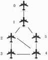
如图1所示,1-5表示该无向图具有5架无人机节点,0表示编队中的长机,无向图指的是编队系统连接图中的每条边都没有连接方向,因此相对于有向图,无向图保守性较低。从图1可以得出拉普拉斯矩阵L和自回路矩阵G分别为:As shown in Figure 1, 1-5 indicate that the undirected graph has 5 UAV nodes, 0 indicates the leader in the formation, and the undirected graph means that each edge in the connection graph of the formation system has no connection direction. Therefore, undirected graphs are less conservative than directed graphs. From Figure 1, it can be concluded that the Laplace matrix L and the self-loop matrix G are:

Figure GSB0000193169270000057

对于编队系统中的长机,将其记为0,其动态方程如下所示:For the leader in the formation system, it is recorded as 0, and its dynamic equation is as follows:

Figure GSB0000193169270000058

y0(t)=Cx0(t)y0 (t)=Cx0 (t)

其中,

Figure GSB0000193169270000061
代表长机的状态向量,
Figure GSB0000193169270000062
代表长机的输出向量。
Figure GSB0000193169270000063
代表长机的系统矩阵,
Figure GSB0000193169270000064
代表长机的输出矩阵。在图G中,长机能被一小部分无人机直接观测到。如果第i架无人机能直接获取到长机的信息,那么图G中存在边(v0,vi),并且控制权重gi>0,那么该无人机为图G中的被控节点。in,
Figure GSB0000193169270000061
represents the state vector of the leader,
Figure GSB0000193169270000062
Represents the output vector of the leader.
Figure GSB0000193169270000063
represents the system matrix of the lead aircraft,
Figure GSB0000193169270000064
Represents the output matrix of the leader. In Figure G, the long aircraft can be directly observed by a small number of UAVs. If the i-th UAV can directly obtain the information of the leader, then there is an edge (v0 , vi ) in graph G, and the control weight gi > 0, then the UAV is the controlled node in graph G .

进一步的,步骤2中所述的故障检测观测器如下:Further, the fault detection observer described instep 2 is as follows:

Figure GSB0000193169270000065

Figure GSB0000193169270000066

其中,,

Figure GSB0000193169270000067
Figure GSB0000193169270000068
分别表示观测器中的状态向量的上界与下界,
Figure GSB0000193169270000069
Figure GSB00001931692700000610
分别表示外界扰动的上下界,矩阵A1是矩阵A与矩阵0的较大者,A2=A-A1,同理,D+为矩阵D与矩阵 0的较大者,D-=D-D+,K是观测器增益矩阵,其中,in,,
Figure GSB0000193169270000067
and
Figure GSB0000193169270000068
represent the upper and lower bounds of the state vector in the observer, respectively,
Figure GSB0000193169270000069
and
Figure GSB00001931692700000610
Respectively represent the upper and lower bounds of external disturbance, matrix A1 is the larger of matrix A andmatrix 0, A2 =AA1 , and similarly, D+ is the larger of matrix D andmatrix 0, D =DD+ , K is the observer gain matrix, where,

Figure GSB00001931692700000611

Figure GSB00001931692700000612
Figure GSB00001931692700000613
分别表示第i个无人机的相对输出估计误差的上下界,给出定义如下:
Figure GSB00001931692700000612
and
Figure GSB00001931692700000613
respectively represent the upper and lower bounds of the relative output estimation error of the i-th UAV, and the definitions are given as follows:

Figure GSB00001931692700000614

Figure GSB00001931692700000615

其中,

Figure GSB00001931692700000616
in,
Figure GSB00001931692700000616

针对第i架无人机,定义其误差上下界,分别为:For the i-th UAV, define the upper and lower bounds of its error, which are:

Figure GSB00001931692700000617

Figure GSB00001931692700000618
but
Figure GSB00001931692700000618

Figure GSB00001931692700000619
可以被改写成:
Figure GSB00001931692700000619
can be rewritten as:

Figure GSB0000193169270000071

Figure GSB0000193169270000072

在无故障情况下,对第i架无人机分别定义误差上下界动态方程:In the case of no fault, the upper and lower bounds of the error dynamic equations are defined for the i-th UAV:

Figure GSB0000193169270000073

Figure GSB0000193169270000074

为了便于阅读,将部分符号简化如下:For readability, some symbols are simplified as follows:

Figure GSB0000193169270000075

则得到:then get:

Figure GSB0000193169270000076

Figure GSB0000193169270000077

进一步的,步骤3中所述的无人机编队系统的全局估计误差方程如下:Further, the global estimation error equation of the UAV formation system described instep 3 is as follows:

Figure GSB0000193169270000078

Figure GSB0000193169270000079

其中,

Figure GSB00001931692700000710
in,
Figure GSB00001931692700000710

Figure GSB00001931692700000711

Figure GSB00001931692700000712

Figure GSB00001931692700000713

IN为N维的单位矩阵,

Figure GSB00001931692700000714
代表矩阵的克罗内克积。这样以便从全局角度来对基于长机-僚机的无人机编队系统进行故障检测研究。IN is an N-dimensional identity matrix,
Figure GSB00001931692700000714
Represents the Kronecker product of a matrix. In this way, the fault detection research of the UAV formation system based on the leader-wingman can be carried out from a global perspective.

当无人机编队系统没有发生执行器故障时,区间观测器的输出定义为:When there is no actuator failure in the UAV formation system, the output of the interval observer is defined as:

Figure GSB00001931692700000715

那么第i架无人机的输出yi(t)应该满足:

Figure GSB00001931692700000716
Then the output yi (t) of the i-th UAV should satisfy:
Figure GSB00001931692700000716

因此,当编队系统处于健康状态时,以下不等式应该成立:Therefore, when the formation system is in a healthy state, the following inequality should hold:

Figure GSB00001931692700000717
否则表明发生故障,应该报警发生故障。
Figure GSB00001931692700000717
Otherwise, it indicates that a failure occurs, and an alarm should be reported.

仿真示例:Simulation example:

定义参考输入ui(t)=[0.5 0.5]T,外界扰动wi=0.1sin(t)Define the reference inputui (t)=[0.5 0.5]T , the external disturbancewi =0.1sin(t)

假设t0=0,考虑以下故障模式:Assuming t0 =0, consider the following failure modes:

无人机1:f1(t)=[f11(t) f12(t)]TDrone 1: f1 (t)=[f11 (t) f12 (t)]T

无人机2:f2(t)=[f21(t) f22(t)]TDrone 2: f2 (t)=[f21 (t) f22 (t)]T

其中,

Figure GSB0000193169270000081
in,
Figure GSB0000193169270000081

Figure GSB0000193169270000082

无人机3、无人机4和无人机5未发生故障。Drone 3,Drone 4, andDrone 5 did not malfunction.

为验证本发明故障检测方法的效果,应用Matlab中的Simulink模块进行仿真实验,假设无人机1发生的是常值执行器故障,无人机2发生的是时变执行器故障,其他无人机均保持正常飞行状态。当编队系统发生故障时,第一架无人机输出残差误差的上界曲线如图2所示,第二架无人机输出残差误差的上界曲线如图3所示。In order to verify the effect of the fault detection method of the present invention, the Simulink module in Matlab is used to carry out a simulation experiment. It is assumed that the failure of the constant value actuator occurs in thedrone 1, the failure of the time-varying actuator occurs in thedrone 2, and the others are unmanned. The aircraft remained in normal flight status. When the formation system fails, the upper bound curve of the output residual error of the first UAV is shown in Figure 2, and the upper bound curve of the output residual error of the second UAV is shown in Figure 3.

从仿真结果可以得出,当无人机编队系统中一架或者多架无人机发生执行器故障时,本发明所设计的区间观测器故障检测方案可以检测出发生故障的节点,且不需要阈值生成器与残差评价函数,很大程度上降低了保守性,有着较强的适应性。本发明对于在执行器故障情况下的无人机编队系统的故障检测具有重要的适用参考价值。From the simulation results, it can be concluded that when one or more UAVs in the UAV formation system have actuator failures, the interval observer failure detection scheme designed in the present invention can detect the failed nodes without requiring The threshold generator and residual evaluation function greatly reduce the conservatism and have strong adaptability. The invention has important applicable reference value for the failure detection of the UAV formation system in the case of actuator failure.

以上具体实施方式是对本发明提出的一种基于区间观测器的无人机编队故障检测方法技术思想的具体支持,不能以此限定本发明的保护范围,凡是按照本发明提出的技术思想,在本发明技术方案基础之上所做的任何改动,均仍属于本发明技术方案的保护范围。The above specific embodiment is a concrete support for the technical idea of a UAV formation fault detection method based on an interval observer proposed by the present invention, and cannot limit the protection scope of the present invention. Any changes made on the basis of the technical solution of the invention still belong to the protection scope of the technical solution of the invention.

Claims (1)

Translated fromChinese
1.一种基于区间观测器的无人机编队故障检测方法,其特征在于,无需残差评价函数和阈值生成器,进行故障检测,该方法包括以下步骤:1. an unmanned aerial vehicle formation fault detection method based on interval observer is characterized in that, without residual evaluation function and threshold generator, carry out fault detection, and this method may further comprise the steps:(1)对无人机编队系统进行建模(1) Modeling the UAV formation system通过图论、状态方程以及输出方程,建立编队系统中各无人机之间的通信连接拓扑,并用无向拓扑图来表示,同时计算出相应的邻接矩阵A和度矩阵D,从而得到拉普拉斯矩阵L;无向切换拓扑图采用
Figure FSB0000194060240000011
表示无人机编队系统的通信拓扑结构;其中,节点集合
Figure FSB0000194060240000012
表示所有的无人机,节点
Figure FSB0000194060240000013
表示第i个无人机,i=1,2,...N;边集合ε表示各无人机之间的通信连接关系,ε中的元素ε=(vi,vj)代表无人机vi的信息可以传送给无人机vj,其中,i,j=1,2,…,N;
Figure FSB00001940602400000127
表示vi的邻居集合,即所有能与vi交互信息的节点集合;邻接矩阵
Figure FSB0000194060240000014
其中如果(vi,vj)∈ε,则aij=1,否则aij=0;度矩阵
Figure FSB0000194060240000015
其中
Figure FSB0000194060240000016
如果(vi,vj)∈ε且(vj,vi)∈ε,那么G为无向图;所述拓扑描述矩阵具体为:Through graph theory, state equation and output equation, the communication connection topology between UAVs in the formation system is established, and represented by an undirected topology graph, and the corresponding adjacency matrix A and degree matrix D are calculated at the same time, so as to obtain Lapp Lass matrix L; the topology of undirected switching adopts
Figure FSB0000194060240000011
Represents the communication topology of the UAV formation system; among them, the set of nodes
Figure FSB0000194060240000012
Represents all drones, nodes
Figure FSB0000194060240000013
Represents the i-th UAV, i=1, 2,...N; the edge set ε represents the communication connection between the UAVs, and the element ε=(vi, v j) in ε represents unmanned The information of the aircraft vi can be transmitted to the drone vj , where i, j = 1, 2, ..., N;
Figure FSB00001940602400000127
Represents the neighbor set of vi , that is, the set of all nodes that can exchange information with vi ; the adjacency matrix
Figure FSB0000194060240000014
where if (vi , vj )∈ε, then aij =1, otherwise aij =0; degree matrix
Figure FSB0000194060240000015
in
Figure FSB0000194060240000016
If (vi , vj )∈ε and (vj , vi )∈ε, then G is an undirected graph; the topology description matrix is specifically:定义拉普拉斯矩阵
Figure FSB0000194060240000017
Define Laplacian Matrix
Figure FSB0000194060240000017
(2)针对无人机编队系统模型,建立基于相对输出估计误差的故障检测区间观测器;(2) According to the UAV formation system model, a fault detection interval observer based on relative output estimation error is established;针对如下的编队系统中的无人机的动态方程:The dynamic equation for the UAV in the formation system as follows:
Figure FSB0000194060240000018
yi(t)=Cxi(t)yi (t)=Cxi (t)其中,
Figure FSB0000194060240000019
代表第i架无人机的状态向量,
Figure FSB00001940602400000110
是第i架无人机的控制输入向量,
Figure FSB00001940602400000111
代表第i架无人机的输出向量,
Figure FSB00001940602400000112
代表外部扰动,
Figure FSB00001940602400000113
是第i架无人机的执行器故障,其中s≤q<n;
Figure FSB00001940602400000114
代表第i架无人机的系统矩阵,
Figure FSB00001940602400000115
代表第i架无人机的输入矩阵,
Figure FSB00001940602400000116
代表第i架无人机的输出矩阵,
Figure FSB00001940602400000117
代表第i架无人机的状态干扰矩阵,
Figure FSB00001940602400000118
代表第i架无人机的故障矩阵,其中D与E矩阵都是已知的列满秩矩阵;对于编队系统中的长机,将其记为0;
in,
Figure FSB0000194060240000019
represents the state vector of the i-th UAV,
Figure FSB00001940602400000110
is the control input vector of the i-th UAV,
Figure FSB00001940602400000111
represents the output vector of the i-th UAV,
Figure FSB00001940602400000112
stands for external disturbance,
Figure FSB00001940602400000113
is the actuator failure of the i-th UAV, where s≤q<n;
Figure FSB00001940602400000114
represents the system matrix of the i-th UAV,
Figure FSB00001940602400000115
represents the input matrix of the i-th UAV,
Figure FSB00001940602400000116
represents the output matrix of the i-th UAV,
Figure FSB00001940602400000117
represents the state-disturbance matrix of the i-th UAV,
Figure FSB00001940602400000118
Represents the failure matrix of the i-th UAV, where D and E matrices are known full-rank matrices; for the leader in the formation system, it is recorded as 0;
针对上述无人机动态方程,设计故障检测观测器如下:Aiming at the above dynamic equation of UAV, the fault detection observer is designed as follows:
Figure FSB00001940602400000119
Figure FSB00001940602400000120
其中,
Figure FSB00001940602400000121
Figure FSB00001940602400000122
分别表示观测器中的状态向量的上界与下界,
Figure FSB00001940602400000123
Figure FSB00001940602400000124
分别表示外界扰动的上下界,矩阵A1是矩阵A与矩阵0的较大者,A2=A-A1,同理,D+为矩阵D与矩阵0的较大者,D-=D-D+,K是观测器增益矩阵,
Figure FSB00001940602400000125
Figure FSB00001940602400000126
分别表示第i个无人机的相对输出估计误差的上下界,给出定义如下:
in,
Figure FSB00001940602400000121
and
Figure FSB00001940602400000122
represent the upper and lower bounds of the state vector in the observer, respectively,
Figure FSB00001940602400000123
and
Figure FSB00001940602400000124
Respectively represent the upper and lower bounds of external disturbance, matrix A1 is the larger of matrix A and matrix 0, A2 =AA1 , and similarly, D+ is the larger of matrix D and matrix 0, D =DD+ , K is the observer gain matrix,
Figure FSB00001940602400000125
and
Figure FSB00001940602400000126
respectively represent the upper and lower bounds of the relative output estimation error of the i-th UAV, and the definitions are given as follows:
Figure FSB0000194060240000021
Figure FSB0000194060240000022
其中,
Figure FSB0000194060240000023
如果第i架无人机能直接获取到长机的信息,那么控制权重gi>0;如果无人机i的信息可以传送给无人机j,i,j=1,2,…,N,则aij=1,否则aij=0;Ni表示第i架无人机的邻居集合,即所有能与第i架无人机交互信息的其他无人机集合;
in,
Figure FSB0000194060240000023
If the i-th UAV can directly obtain the information of the leader, then the control weight gi >0; if the information of UAV i can be transmitted to UAV j, i, j=1, 2, ..., N, Then aij = 1, otherwise aij = 0; Ni represents the neighbor set of thei -th UAV, that is, the set of all other UAVs that can exchange information with the i-th UAV;
针对第i架无人机,定义其误差上下界,分别为:For the i-th UAV, define the upper and lower bounds of its error, which are:
Figure FSB0000194060240000024
Figure FSB0000194060240000025
可以被改写成:
but
Figure FSB0000194060240000025
can be rewritten as:
Figure FSB0000194060240000026
Figure FSB0000194060240000027
在无故障情况下,对第i架无人机分别定义误差上下界动态方程:In the case of no fault, the upper and lower bounds of the error dynamic equations are defined for the i-th UAV:
Figure FSB0000194060240000028
Figure FSB0000194060240000029
为了便于阅读,将部分符号简化如下:For readability, some symbols are simplified as follows:
Figure FSB00001940602400000210
则得到:then get:
Figure FSB00001940602400000211
Figure FSB00001940602400000212
(3)通过理论推导得到无人机编队系统的全局估计误差方程,对该全局估计误差方程进行稳定性验证并且最终得到故障检测算法;(3) Obtain the global estimation error equation of the UAV formation system through theoretical derivation, verify the stability of the global estimation error equation and finally obtain the fault detection algorithm;全局估计误差方程如下:The global estimation error equation is as follows:
Figure FSB00001940602400000213
Figure FSB00001940602400000214
其中,
Figure FSB0000194060240000031
in,
Figure FSB0000194060240000031
Figure FSB0000194060240000032
Figure FSB0000194060240000033
Figure FSB0000194060240000034
IN为N维的单位矩阵,
Figure FSB0000194060240000035
代表矩阵的克罗内克积,L是拉普拉斯矩阵,G为标定矩阵;
IN is an N-dimensional identity matrix,
Figure FSB0000194060240000035
Represents the Kronecker product of the matrix, L is the Laplace matrix, and G is the calibration matrix;
考虑如下连续系统:Consider the following continuous system:
Figure FSB0000194060240000036
其中,矩阵A为梅茨勒矩阵,
Figure FSB0000194060240000037
并且
Figure FSB0000194060240000038
Among them, the matrix A is the Metzler matrix,
Figure FSB0000194060240000037
and
Figure FSB0000194060240000038
如果系统初始状态x(0)≥0,那么当t≥0时,x(t)≥0恒成立;If the initial state of the system x(0)≥0, then when t≥0, x(t)≥0 is always established;由此引出如下定理:This leads to the following theorem:对于给定的通信拓扑,如果
Figure FSB0000194060240000039
既是梅茨勒矩阵,又是赫尔维茨矩阵,那么当无人机编队系统无故障时,故障检测观测器为区间观测器,并且使得
Figure FSB00001940602400000310
成立;
For a given communication topology, if
Figure FSB0000194060240000039
It is both a Metzler matrix and a Hurwitz matrix, then when the UAV formation system has no faults, the fault detection observer is an interval observer, and makes
Figure FSB00001940602400000310
established;
当无人机编队系统没有发生执行器故障时,区间观测器的输出定义为:When there is no actuator failure in the UAV formation system, the output of the interval observer is defined as:
Figure FSB00001940602400000311
那么第i架无人机的输出yi(t)应该满足:
Figure FSB00001940602400000312
Then the output yi (t) of the i-th UAV should satisfy:
Figure FSB00001940602400000312
因此,当编队系统处于健康状态时,以下不等式应该成立:Therefore, when the formation system is in a healthy state, the following inequality should hold:
Figure FSB00001940602400000313
否则表明发生故障,应该报警发生故障。
Figure FSB00001940602400000313
Otherwise, it indicates that a failure occurs, and an alarm should be reported.
CN201910274124.1A2019-04-042019-04-04 A fault detection method for UAV formation system based on interval observerExpired - Fee RelatedCN109884902B (en)

Priority Applications (1)

Application NumberPriority DateFiling DateTitle
CN201910274124.1ACN109884902B (en)2019-04-042019-04-04 A fault detection method for UAV formation system based on interval observer

Applications Claiming Priority (1)

Application NumberPriority DateFiling DateTitle
CN201910274124.1ACN109884902B (en)2019-04-042019-04-04 A fault detection method for UAV formation system based on interval observer

Publications (2)

Publication NumberPublication Date
CN109884902A CN109884902A (en)2019-06-14
CN109884902Btrue CN109884902B (en)2021-09-07

Family

ID=66936283

Family Applications (1)

Application NumberTitlePriority DateFiling Date
CN201910274124.1AExpired - Fee RelatedCN109884902B (en)2019-04-042019-04-04 A fault detection method for UAV formation system based on interval observer

Country Status (1)

CountryLink
CN (1)CN109884902B (en)

Families Citing this family (7)

* Cited by examiner, † Cited by third party
Publication numberPriority datePublication dateAssigneeTitle
CN112291810B (en)*2020-11-022022-02-08北京邮电大学Network splitting detection method and device for unmanned aerial vehicle network
CN112947391B (en)*2021-04-052022-04-01西北工业大学 A Micro-fault Diagnosis Method for Flight Control System Actuators Based on TOMFIR Residuals
CN113467517A (en)*2021-07-302021-10-01河北科技大学Flight control method and system of unmanned aerial vehicle cluster under fault condition
CN114326715B (en)*2021-12-092023-10-03东南大学Formation control method and device for variable-dimension multi-agent system
CN115328200A (en)*2022-08-232022-11-11苏州大学 Consistent control method of aircraft swarm system based on state estimation
CN116224807B (en)*2023-05-082023-07-21西北工业大学Unmanned aerial vehicle formation fault detection method based on distributed observer
CN118897499B (en)*2024-10-092025-03-14中国人民解放军海军航空大学Distributed topology switching cooperative control method

Citations (3)

* Cited by examiner, † Cited by third party
Publication numberPriority datePublication dateAssigneeTitle
CN105242544A (en)*2015-10-302016-01-13山东科技大学Non-linear multi-unmanned-aerial-vehicle-system fault-tolerance formation control method with consideration of random disturbance
CN107329083A (en)*2017-07-282017-11-07南京航空航天大学For the method for diagnosing faults of bullet train traction electric machine nonlinear system sensor
CN109491244A (en)*2017-09-132019-03-19南京航空航天大学A kind of unmanned plane fleet system method for diagnosing faults based on sliding mode observer

Patent Citations (3)

* Cited by examiner, † Cited by third party
Publication numberPriority datePublication dateAssigneeTitle
CN105242544A (en)*2015-10-302016-01-13山东科技大学Non-linear multi-unmanned-aerial-vehicle-system fault-tolerance formation control method with consideration of random disturbance
CN107329083A (en)*2017-07-282017-11-07南京航空航天大学For the method for diagnosing faults of bullet train traction electric machine nonlinear system sensor
CN109491244A (en)*2017-09-132019-03-19南京航空航天大学A kind of unmanned plane fleet system method for diagnosing faults based on sliding mode observer

Non-Patent Citations (4)

* Cited by examiner, † Cited by third party
Title
Adaptive observer-based fast fault estimation of a leader-follower linear multi-agent system with actuator faults;Liu Guosheng等;《2015 34th Chinese Control Conference (CCC)》;IEEE;20150914;第6340-6344页*
Interval observer-based fault detection in finite frequency domain for discrete-time fuzzy systems;Zhi-HuiZhang等;《Neurocomputing》;Elsevier;20180523;第310卷;第38-45页*
具有切换拓扑结构的多智能体系统故障诊断研究;崔阳;《中国优秀硕士学位论文全文数据库 信息科技辑》;中国学术期刊(光盘版)电子杂志社;20190215(第02期);第1-69页*
分布式飞行控制系统故障诊断研究;刘国胜;《中国优秀硕士学位论文全文数据库 工程科技Ⅱ辑》;中国学术期刊(光盘版)电子杂志社;20180315(第03期);摘要、第11-12、17-20页*

Also Published As

Publication numberPublication date
CN109884902A (en)2019-06-14

Similar Documents

PublicationPublication DateTitle
CN109884902B (en) A fault detection method for UAV formation system based on interval observer
CN109557818B (en)Sliding mode fault-tolerant control method of multi-agent tracking system with multiple faults
Yu et al.Distributed finite-time fault-tolerant containment control for multiple unmanned aerial vehicles
CN105204499B (en)Helicopter collaboration formation method for diagnosing faults based on Unknown Input Observer
CN108427401B (en)Flight control system cooperative fault diagnosis method with joint connectivity topology
CN107797454B (en)Multi-agent system based on finite-time control cooperates with fault tolerant control method
CN110161847B (en) A sensor fault estimation method for UAV formation system based on distributed singular observers
CN106444701B (en)Leader-follower type multi-agent system finite time Robust Fault Diagnosis design method
CN113268084B (en)Intelligent fault-tolerant control method for unmanned aerial vehicle formation
CN110414125B (en)Event-driven spacecraft rendezvous fault diagnosis and filter design method
CN107422741B (en)Learning-based cluster flight distributed attitude tracking control method for preserving preset performance
CN110058519A (en)A kind of active formation fault tolerant control method based on quick self-adapted technology
CN108803317A (en)Adaptive multivariable quadrotor drone finite time fault tolerant control method
CN111142549B (en) A UAV attitude control system anti-jamming attack detection and self-healing controller and control method
Gai et al.Dynamic Event-Triggered Hᵢ/H∞ Optimization Approach to Fault Detection for Unmanned Aerial Vehicles
CN107315421B (en) A Distributed Speed Sensor Fault Diagnosis Method for Delayed UAV Formation
CN116692031A (en)Spacecraft cluster attitude cooperative control method under interference fault mixing condition
CN117148863B (en) A fault-tolerant collaborative control method for swarm drones under compound faults
Liu et al.Integrated adaptive fault-tolerant h infinity output feedback control with adaptive fault identification
CN105182990A (en)Robust control method of three-DOF model helicopter with output limits
CN108646712A (en)Fault tolerant control system with indeterminate system of actuator failure
CN117177208A (en) A collaborative fault-tolerant control method for clustered UAVs considering random communication delays
Yuan et al.Dynamic event-triggered fault-tolerant cooperative resilient tracking control with prescribed performance for UAVs
Cui et al.Fixed‐time disturbance observer based distributed cooperative containment control with fixed‐time anti‐saturation compensator for multi‐unmanned aerial vehicles
Guo et al.Adaptive event-triggered PIO-based anti-disturbance fault-tolerant control for MASs with process and sensor faults

Legal Events

DateCodeTitleDescription
PB01Publication
PB01Publication
SE01Entry into force of request for substantive examination
GR01Patent grant
GR01Patent grant
CF01Termination of patent right due to non-payment of annual fee

Granted publication date:20210907

CF01Termination of patent right due to non-payment of annual fee

[8]ページ先頭

©2009-2025 Movatter.jp