CN109884711B - Non-contact coal and rock electrification monitoring sensor based on induction principle - Google Patents
Non-contact coal and rock electrification monitoring sensor based on induction principleDownload PDFInfo
- Publication number
- CN109884711B CN109884711BCN201811404867.8ACN201811404867ACN109884711BCN 109884711 BCN109884711 BCN 109884711BCN 201811404867 ACN201811404867 ACN 201811404867ACN 109884711 BCN109884711 BCN 109884711B
- Authority
- CN
- China
- Prior art keywords
- circuit
- sensor
- output
- signal
- charge
- Prior art date
- Legal status (The legal status is an assumption and is not a legal conclusion. Google has not performed a legal analysis and makes no representation as to the accuracy of the status listed.)
- Active
Links
- 239000003245coalSubstances0.000titleclaimsabstractdescription20
- 239000011435rockSubstances0.000titleclaimsabstractdescription19
- 238000012544monitoring processMethods0.000titleclaimsabstractdescription18
- 230000006698inductionEffects0.000titleclaimsabstractdescription11
- 239000003990capacitorSubstances0.000claimsabstractdescription26
- 239000011810insulating materialSubstances0.000claimsabstractdescription11
- 230000010354integrationEffects0.000claimsabstractdescription11
- 239000000463materialSubstances0.000claimsdescription7
- 239000010935stainless steelSubstances0.000claimsdescription5
- 229910001220stainless steelInorganic materials0.000claimsdescription5
- 238000012545processingMethods0.000claimsdescription4
- 238000009825accumulationMethods0.000claimsdescription3
- 238000009434installationMethods0.000claimsdescription3
- 239000000956alloySubstances0.000claimsdescription2
- 238000005553drillingMethods0.000claimsdescription2
- 238000002955isolationMethods0.000claimsdescription2
- 229910001004magnetic alloyInorganic materials0.000claimsdescription2
- -1polytetrafluoroethylenePolymers0.000claimsdescription2
- 229920001343polytetrafluoroethylenePolymers0.000claimsdescription2
- 239000004810polytetrafluoroethyleneSubstances0.000claimsdescription2
- 238000007789sealingMethods0.000claimsdescription2
- 125000000391vinyl groupChemical group[H]C([*])=C([H])[H]0.000claims1
- 229920002554vinyl polymerPolymers0.000claims1
- 238000000034methodMethods0.000abstractdescription11
- 238000005065miningMethods0.000abstract1
- 230000035945sensitivityEffects0.000abstract1
- 238000010586diagramMethods0.000description4
- 238000005259measurementMethods0.000description4
- LAXBNTIAOJWAOP-UHFFFAOYSA-N2-chlorobiphenylChemical compoundClC1=CC=CC=C1C1=CC=CC=C1LAXBNTIAOJWAOP-UHFFFAOYSA-N0.000description2
- 101710149812Pyruvate carboxylase 1Proteins0.000description2
- 230000003321amplificationEffects0.000description2
- 238000013480data collectionMethods0.000description2
- 230000000694effectsEffects0.000description2
- 238000003199nucleic acid amplification methodMethods0.000description2
- 230000009286beneficial effectEffects0.000description1
- 239000002817coal dustSubstances0.000description1
- 238000011161developmentMethods0.000description1
- 238000007599dischargingMethods0.000description1
- 230000005611electricityEffects0.000description1
- 230000005672electromagnetic fieldEffects0.000description1
- 230000005670electromagnetic radiationEffects0.000description1
- 230000007613environmental effectEffects0.000description1
- 238000011900installation processMethods0.000description1
- 239000012774insulation materialSubstances0.000description1
- 230000005389magnetismEffects0.000description1
Images


Landscapes
- Investigating Or Analyzing Materials By The Use Of Electric Means (AREA)
- Emergency Alarm Devices (AREA)
- Geophysics And Detection Of Objects (AREA)
Abstract
Translated fromChinese
Description
Translated fromChinese技术领域technical field
本发明属于煤岩体带电量监测技术领域,具体涉及一种基于感应原理的非接触式煤、岩带电监测传感器。The invention belongs to the technical field of coal and rock mass charging monitoring, and in particular relates to a non-contact coal and rock charging monitoring sensor based on an induction principle.
背景技术Background technique
煤岩破裂过程伴随有声、光、热、电、磁等物理信息,基于煤岩破坏过程不同物理信息,国内外专家学者提出声发射、微震、红外温度、电磁辐射、电荷等许多方法用于煤矿冲击地压等动力灾害监测预警。受煤矿地质条件、井下潮湿、环境噪声等因素影响,一些监测方法预测预警准确率不高,未能达到现场实际应用要求,原因是一些传感器使用过程中与煤壁接触,安装过程中接触程度差异导致监测效果不佳。The coal rock fracture process is accompanied by physical information such as sound, light, heat, electricity, and magnetism. Based on the different physical information of the coal rock fracture process, experts and scholars at home and abroad have proposed many methods such as acoustic emission, microseismic, infrared temperature, electromagnetic radiation, and electric charge for coal mines. Monitoring and early warning of dynamic disasters such as rock burst. Affected by factors such as coal mine geological conditions, underground humidity, environmental noise, etc., some monitoring methods have low prediction and early warning accuracy and fail to meet the actual application requirements. The reason is that some sensors are in contact with the coal wall during use, and the degree of contact during installation is different lead to poor monitoring.
专利号为ZL200810013003.4的岩体电荷辐射仪中提供了一种岩体电荷测量仪器,然而现场应用过程中,较难适应井下环境,传感器内部电路复杂,受井下环境干扰较大,数据采集过程不稳定,难以满足现场监测需要,因此急需研发更加有效的非接触方式、适用性强的煤、岩带电监测传感器。The rock mass charge radiometer with the patent number of ZL200810013003.4 provides a rock mass charge measurement instrument. However, in the field application process, it is difficult to adapt to the underground environment, the internal circuit of the sensor is complex, and it is greatly interfered by the underground environment. The data acquisition process It is unstable and difficult to meet the needs of on-site monitoring. Therefore, it is urgent to develop more effective non-contact methods and highly applicable coal and rock live monitoring sensors.
发明内容SUMMARY OF THE INVENTION
本发明提供一种基于感应原理的非接触式煤、岩带电监测传感器,传感器外套一端安装有信号输出接口,另一端安装有敏感元件,敏感元件通过屏蔽连接线与内部的传感器电路PCB板连接;传感器电路PCB板的阻抗匹配电路与敏感元件连接,用于接收信号;积分电容放电电路、偏置补偿电路、电荷积分电路与阻抗匹配电路的信号输出端连接,用于处理信号;处理后的信号与放大电路信号输入端连接,放大后,通过信号输出接口向外输出。通过上述结构,本发明解决了现有技术中存在的安装过程繁琐、监测效果不理想等技术问题。The invention provides a non-contact coal and rock electrification monitoring sensor based on the induction principle. One end of the sensor jacket is provided with a signal output interface, and the other end is provided with a sensitive element, and the sensitive element is connected to an internal sensor circuit PCB board through a shielded connecting wire; The impedance matching circuit of the sensor circuit PCB is connected to the sensitive element for receiving signals; the integrating capacitor discharge circuit, the bias compensation circuit, and the charge integration circuit are connected to the signal output end of the impedance matching circuit for processing the signal; the processed signal It is connected with the signal input end of the amplifying circuit, and after being amplified, it is outputted through the signal output interface. Through the above structure, the present invention solves the technical problems existing in the prior art, such as complicated installation process and unsatisfactory monitoring effect.
为了实现上述目的,本发明创造采用的技术方案为:一种基于感应原理的非接触式煤、岩带电监测传感器,包括传感器外套,其特征在于:传感器外套一端安装有信号输出接口,另一端安装有敏感元件,敏感元件通过屏蔽连接线与内部的传感器电路PCB板连接;传感器电路PCB板的阻抗匹配电路与敏感元件连接,用于接收信号;积分电容放电电路、偏置补偿电路、电荷积分电路与阻抗匹配电路的信号输出端连接,用于处理信号;处理后的信号与放大电路信号输入端连接,放大后,通过信号输出接口向外输出。In order to achieve the above purpose, the technical solution adopted by the present invention is as follows: a non-contact coal and rock live monitoring sensor based on the induction principle, comprising a sensor jacket, characterized in that: one end of the sensor jacket is installed with a signal output interface, and the other end is installed with There are sensitive elements, and the sensitive elements are connected to the internal sensor circuit PCB board through shielded connecting wires; the impedance matching circuit of the sensor circuit PCB board is connected to the sensitive elements for receiving signals; the integral capacitor discharge circuit, the bias compensation circuit, and the charge integration circuit It is connected with the signal output end of the impedance matching circuit for processing the signal; the processed signal is connected with the signal input end of the amplifying circuit, and after being amplified, it is outputted through the signal output interface.
所述的传感器外套两端采用前端盖和后端盖进行密封,将传感器电路PCB板封装在内部;信号输出接口和敏感元件露在传感器外套外部。The two ends of the sensor jacket are sealed with a front end cover and a rear end cover, and the sensor circuit PCB board is encapsulated inside; the signal output interface and the sensitive element are exposed outside the sensor jacket.
所述的敏感元件与前端盖之间设有绝缘材料体,屏蔽连接线穿过绝缘材料体与内部的传感器电路PCB板连接。An insulating material body is arranged between the sensitive element and the front end cover, and the shielding connecting wire is connected to the inner sensor circuit PCB board through the insulating material body.
所述的前端盖和后端盖通过螺纹柱和螺钉固定在传感器外套的两端。The front end cover and the rear end cover are fixed on both ends of the sensor casing by threaded posts and screws.
所述的阻抗匹配电路:敏感元件感应电荷由P6输入,P6输出端连接阻抗匹配R1,阻抗匹配R1输出端与电荷积分电路连接。In the impedance matching circuit: the sensing element induced charge is input by P6, the output end of P6 is connected to the impedance matching R1, and the output end of the impedance matching R1 is connected to the charge integrating circuit.
偏置补偿电路:由运放U1A和运放U2A构成,U1A与电阻R8和R5构成电压比较器,由稳压管D3、D4将电压钳位在两个基准电压,通过电阻R4,R6分压,再由电压跟随器U2A为电荷积分器提供稳定的偏置电压。Bias compensation circuit: composed of operational amplifier U1A and operational amplifier U2A, U1A and resistors R8 and R5 constitute a voltage comparator, the voltage is clamped at two reference voltages by voltage regulator tubes D3 and D4, and the voltage is divided by resistors R4 and R6 , and then the voltage follower U2A provides a stable bias voltage for the charge integrator.
电荷积分电路:由放大器U2B和积分电容C7组成,电荷输入和偏置补偿电路的输出连接U2B的负输出端和C7的N1端,U2B的正输入端接地;偏置补偿电路在电容C7的N1端形成稳定的偏置电压,根据运放U2B虚断的原理,电荷输入通过电容C7在N2端累积出电压,电压值表征单位时间电荷的累积量。Charge integration circuit: composed of amplifier U2B and integrating capacitor C7, the charge input and the output of the offset compensation circuit are connected to the negative output terminal of U2B and the N1 terminal of C7, and the positive input terminal of U2B is grounded; the offset compensation circuit is connected to the N1 of the capacitor C7 A stable bias voltage is formed at the terminal. According to the principle of virtual disconnection of the operational amplifier U2B, the charge input accumulates a voltage at the N2 terminal through the capacitor C7, and the voltage value represents the accumulated amount of charge per unit time.
电荷积分电路的输出一方面由P8直接输出,另一方面通过放大器U1B进行输出放大,由P9输出,通过改变R10和R11阻值改变输出放大倍数。On the one hand, the output of the charge integration circuit is directly output by P8, on the other hand, the output is amplified by the amplifier U1B, output by P9, and the output magnification is changed by changing the resistance values of R10 and R11.
本发明创造的有益效果为:一种基于感应原理的非接触式煤、岩带电监测传感器,传感器外套一端安装有信号输出接口,另一端安装有敏感元件,敏感元件通过屏蔽连接线与内部的传感器电路PCB板连接;传感器电路PCB板的阻抗匹配电路与敏感元件连接,用于接收信号;积分电容放电电路、偏置补偿电路、电荷积分电路与阻抗匹配电路的信号输出端连接,用于处理信号;处理后的信号与放大电路信号输入端连接,放大后,通过信号输出接口向外输出。本发明通过上述结构,提供了一种结构简单、使用方便、感应测量效果好的非接触式煤、岩带电监测传感器。The beneficial effects created by the invention are as follows: a non-contact coal and rock electrification monitoring sensor based on the induction principle, one end of the sensor jacket is installed with a signal output interface, the other end is installed with a sensitive element, and the sensitive element is connected to the internal sensor through a shielded connecting wire The circuit PCB board is connected; the impedance matching circuit of the sensor circuit PCB board is connected with the sensitive element to receive the signal; the integral capacitor discharge circuit, the bias compensation circuit, the charge integration circuit and the signal output terminal of the impedance matching circuit are connected to process the signal ; The processed signal is connected to the signal input end of the amplifying circuit, and after being amplified, it is outputted through the signal output interface. Through the above structure, the present invention provides a non-contact coal and rock electrification monitoring sensor with simple structure, convenient use and good induction measurement effect.
附图说明Description of drawings
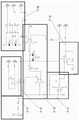
图1:本发明创造结构示意图。Figure 1: Schematic diagram of the structure of the invention.
图2:本发明创造传感器电路PCB板电路框图。Figure 2: The circuit block diagram of the sensor circuit PCB board created by the present invention.
图3:本发明创造传感器电路PCB板电路原理图。Figure 3: The circuit schematic diagram of the sensor circuit PCB board created by the present invention.
具体实施方式Detailed ways
一种基于感应原理的非接触式煤、岩带电监测传感器,包括传感器外套6,其特征在于:传感器外套6一端安装有信号输出接口10,另一端安装有敏感元件2,敏感元件2通过屏蔽连接线9与内部的传感器电路PCB板1连接;传感器电路PCB板1的阻抗匹配电路1-1与敏感元件2连接,用于接收信号;积分电容放电电路1-2、偏置补偿电路1-3、电荷积分电路1-4与阻抗匹配电路1-1的信号输出端连接,用于处理信号;处理后的信号与放大电路1-5信号输入端连接,放大后,通过信号输出接口10向外输出。A non-contact coal and rock electrification monitoring sensor based on induction principle, comprising a sensor jacket 6, characterized in that: one end of the sensor jacket 6 is provided with a
其机械结构如图1所示,由于煤矿井下工作环境复杂,具有潮湿、高应力、高瓦斯、高煤尘等特点,选择敏感、耐用的传感器敏感元件材料、密封绝缘材料以及低耗电的井下适应能力是传感器研制过程需重点考虑的问题。为此,敏感元件2材料选择电阻率小的软磁合金材料作为传感器的敏感元件材料,可加工成圆形、针形等不同结构,不同结构其敏感特性不同。选择电阻率大的聚四氟乙烯绝缘材料作为敏感元件2与传感器外套6之间的绝缘材料体3的隔离材料。Its mechanical structure is shown in Figure 1. Due to the complex underground working environment of coal mines, which has the characteristics of humidity, high stress, high gas, and high coal dust, select sensitive and durable sensor materials, sealing insulation materials and low power consumption underground. Adaptability is a key consideration in the process of sensor development. For this reason, the material of the
所述的传感器外套6两端采用前端盖4和后端盖5进行密封,将传感器电路PCB板1封装在内部;信号输出接口10和敏感元件2露在传感器外套6外部。敏感元件2与前端盖4之间设有绝缘材料体3,屏蔽连接线9穿过绝缘材料体3与内部的传感器电路PCB板1连接。前端盖4和后端盖5通过螺纹柱7和螺钉8固定在传感器外套6的两端。Both ends of the sensor casing 6 are sealed by the front cover 4 and the
其中传感器外套6采用Φ=28mm不锈钢圆管,方便现场钻孔内部安装。不锈钢圆管壁厚1.5mm,一方面保护传感器内部结构;另一方面防止外界的电磁信号干扰。前端盖4和后端盖5材料为不锈钢,通过螺钉8与传感器外套和传感器电路PCB板1的螺纹柱7连接。采用通过屏蔽线传感器外壳与大地连接,传感器的信号输出接口10采用5芯屏蔽线。Among them, the sensor jacket 6 is made of Φ=28mm stainless steel round pipe, which is convenient for internal installation of on-site drilling. The wall thickness of the stainless steel round tube is 1.5mm, which protects the internal structure of the sensor on the one hand, and prevents external electromagnetic signal interference on the other hand. The front end cover 4 and the
煤岩破裂产生电荷量极其微弱,同时受到外界电磁场等因素干扰,传感器将敏感元件的高阻抗输入变换为低阻抗输出,将输入电荷量转换为输出电压量,电压放大电路对电压量进行放大处理,最后由数据采集系统进行数据采集。因此,传感器电路PCB板1主要包括一个低噪声、高输入阻抗的阻抗匹配电路1-1和电荷积分电路1-4、提供稳定的偏置电压的偏置补偿电路1-3、可调增益的精密输出放大电路1-5;积分电容放电电路1-2和电源电路1-6。The amount of charge generated by the fracture of coal and rock is extremely weak, and at the same time, it is interfered by external electromagnetic fields and other factors. The sensor converts the high-impedance input of the sensitive element into a low-impedance output, converts the input charge into the output voltage, and the voltage amplifier circuit amplifies the voltage. , and finally the data collection system is used for data collection. Therefore, the sensor circuit PCB board 1 mainly includes an impedance matching circuit 1-1 and a charge integration circuit 1-4 with low noise and high input impedance, a bias compensation circuit 1-3 for providing a stable bias voltage, an adjustable gain Precision output amplifier circuit 1-5; integrating capacitor discharge circuit 1-2 and power supply circuit 1-6.
如图2所示,传感器电路图为交流式电荷放大系统,电荷采集器通过阻抗匹配输入至电荷积分器,利用放大器“虚地”的特性对电荷进行积分形成电压量。通过补偿电路对电荷积分器的偏置电压进行补偿,稳定输出。由于采集微量电荷输出电压很小,输出部分提供两种输出方式,一个是直接输入,一个是经放大器后输出。电源电路1-6为系统各电路提供电源。由于电荷积分器的不稳定性,为了防止测量误差累积,每次测量前需要积分电容放电器对积分电容进行放电。As shown in Figure 2, the sensor circuit diagram is an AC-type charge amplification system. The charge collector is input to the charge integrator through impedance matching, and the charge is integrated to form a voltage quantity by using the "virtual ground" characteristic of the amplifier. The offset voltage of the charge integrator is compensated by the compensation circuit to stabilize the output. Since the output voltage of the collected trace charge is very small, the output part provides two output modes, one is direct input, and the other is output after the amplifier. Power circuits 1-6 provide power for each circuit of the system. Due to the instability of the charge integrator, in order to prevent the accumulation of measurement errors, an integrating capacitor discharger is required to discharge the integrating capacitor before each measurement.
具体电路如下:The specific circuit is as follows:
所述的阻抗匹配电路1-1:敏感元件感应电荷由P6输入,P6输出端连接阻抗匹配R1,阻抗匹配R1输出端与电荷积分电路1-4连接。The impedance matching circuit 1-1: the sensing element induced charge is input by P6, the output end of P6 is connected to the impedance matching R1, and the output end of the impedance matching R1 is connected to the charge integrating circuit 1-4.
积分电容放电电路1-2:P2为电源负极,P4为电源正极,P2与P5直接相连,P4通过外接开关与P1相连,开关闭合使继电器K1吸合,电容C7形成放电回路,进行放电。电容C3为滤波电容,稳定K1的触发电平。Integral capacitor discharge circuit 1-2: P2 is the negative pole of the power supply, P4 is the positive pole of the power supply, P2 is directly connected to P5, P4 is connected to P1 through an external switch, the switch is closed to make the relay K1 pull in, and the capacitor C7 forms a discharge loop for discharging. Capacitor C3 is a filter capacitor to stabilize the trigger level of K1.
电荷积分电路1-4:由放大器U2B和积分电容C7组成,电荷输入和偏置补偿电路的输出连接U2B的负输出端和C7的N1端,U2B的正输入端接地。偏置补偿电路在电容C7的N1端形成稳定的偏置电压,根据运放U2B虚断的原理,电荷输入通过电容C7在N2端累积出电压,这个电压值可以表征单位时间电荷的累积量,由P8测得。Charge integrating circuit 1-4: It is composed of amplifier U2B and integrating capacitor C7. The charge input and the output of the offset compensation circuit are connected to the negative output terminal of U2B and the N1 terminal of C7, and the positive input terminal of U2B is grounded. The bias compensation circuit forms a stable bias voltage at the N1 terminal of the capacitor C7. According to the principle of the virtual break of the operational amplifier U2B, the charge input accumulates a voltage at the N2 terminal through the capacitor C7. This voltage value can represent the accumulation of charge per unit time. Measured by P8.
偏置补偿电路1-3:由运放U1A和运放U2A构成,U1A与电阻R8和R5构成电压比较器,由稳压管D3,D4将电压钳位在两个基准电压,通过电阻R4,R6分压,再由电压跟随器U2A为电荷积分器提供稳定的偏置电压,R7提供稳定的基准电压。Bias compensation circuit 1-3: composed of operational amplifier U1A and operational amplifier U2A, U1A and resistors R8 and R5 constitute a voltage comparator, the voltage is clamped at two reference voltages by voltage regulator tubes D3 and D4, and through resistor R4, R6 divides the voltage, and then the voltage follower U2A provides a stable bias voltage for the charge integrator, and R7 provides a stable reference voltage.
放大电路1-5:电荷积分电路1-4的输出一方面由P8直接输出,另一方面通过放大器U1B进行输出放大,由P9输出,通过改变R10和R11阻值改变输出放大倍数。Amplifying circuit 1-5: The output of the charge integration circuit 1-4 is directly output by P8 on the one hand, and the output is amplified by the amplifier U1B on the other hand, and is output by P9, and the output magnification is changed by changing the resistance values of R10 and R11.
Claims (3)
Translated fromChinesePriority Applications (1)
| Application Number | Priority Date | Filing Date | Title |
|---|---|---|---|
| CN201811404867.8ACN109884711B (en) | 2018-11-23 | 2018-11-23 | Non-contact coal and rock electrification monitoring sensor based on induction principle |
Applications Claiming Priority (1)
| Application Number | Priority Date | Filing Date | Title |
|---|---|---|---|
| CN201811404867.8ACN109884711B (en) | 2018-11-23 | 2018-11-23 | Non-contact coal and rock electrification monitoring sensor based on induction principle |
Publications (2)
| Publication Number | Publication Date |
|---|---|
| CN109884711A CN109884711A (en) | 2019-06-14 |
| CN109884711Btrue CN109884711B (en) | 2022-09-13 |
Family
ID=66924964
Family Applications (1)
| Application Number | Title | Priority Date | Filing Date |
|---|---|---|---|
| CN201811404867.8AActiveCN109884711B (en) | 2018-11-23 | 2018-11-23 | Non-contact coal and rock electrification monitoring sensor based on induction principle |
Country Status (1)
| Country | Link |
|---|---|
| CN (1) | CN109884711B (en) |
Families Citing this family (2)
| Publication number | Priority date | Publication date | Assignee | Title |
|---|---|---|---|---|
| CN116165720A (en)* | 2022-12-05 | 2023-05-26 | 辽宁大学 | A location method for predicting the main fracture source of coal and rock based on induced charge |
| CN116067251A (en)* | 2022-12-26 | 2023-05-05 | 辽宁大学 | Self-adaptive centering positioning device for coal rock drilling charge sensor and using method |
Citations (10)
| Publication number | Priority date | Publication date | Assignee | Title |
|---|---|---|---|---|
| CN201811999U (en)* | 2010-09-01 | 2011-04-27 | 辽宁工程技术大学 | Non-contact electrostatic induction sensor |
| CN202602594U (en)* | 2012-05-30 | 2012-12-12 | 四川兴达明科机电工程有限公司 | Charge amplifier |
| CN103116099A (en)* | 2013-01-25 | 2013-05-22 | 辽宁工程技术大学 | Testing device for coal-rock temperature affection on coal-rock electric charges |
| CN103577015A (en)* | 2012-08-01 | 2014-02-12 | 阿尔卑斯电气株式会社 | Electrostatic capacitance detection circuit and input device |
| CN105043563A (en)* | 2015-08-28 | 2015-11-11 | 华南师范大学 | Integral gating single-photon detector integral capacitor discharge circuit and method |
| CN105785430A (en)* | 2016-05-09 | 2016-07-20 | 辽宁工程技术大学 | Real-time monitoring system and method for mine earthquake |
| CN206038780U (en)* | 2016-08-30 | 2017-03-22 | 上海测振自动化仪器有限公司 | Prevent high -pressure electric charge sensor |
| CN107192445A (en)* | 2017-07-31 | 2017-09-22 | 江苏省电力试验研究院有限公司 | A kind of strong vibration sensor circuit and signal acquiring system for primary cut-out |
| CN107636972A (en)* | 2015-01-16 | 2018-01-26 | 离子地球物理公司 | Capacitance type sensor is directly coupled to Δ Σ converters |
| CN107688798A (en)* | 2017-09-30 | 2018-02-13 | 苏州迈瑞微电子有限公司 | A kind of charge type sensor and sensor array and the acquisition methods of integrating circuit mismatch adjusting parameter with it |
Family Cites Families (6)
| Publication number | Priority date | Publication date | Assignee | Title |
|---|---|---|---|---|
| JP2784396B2 (en)* | 1994-06-08 | 1998-08-06 | セイコープレシジョン株式会社 | Capacitive sensor |
| CN2535807Y (en)* | 2002-04-15 | 2003-02-12 | 清华大学 | Weak-signal testing circuit based on switch capacitor integrator |
| CH702300A1 (en)* | 2009-11-25 | 2011-05-31 | Kistler Holding Ag | Digital charge amplifier. |
| JP2013540259A (en)* | 2010-06-30 | 2013-10-31 | ライフ テクノロジーズ コーポレーション | Array column integrator |
| FR3025606B1 (en)* | 2014-09-10 | 2016-09-23 | Commissariat Energie Atomique | DEVICE FOR CURRENT MEASUREMENT |
| CN107589316B (en)* | 2017-08-25 | 2019-12-20 | 中国科学院近代物理研究所 | Charge measurement circuit |
- 2018
- 2018-11-23CNCN201811404867.8Apatent/CN109884711B/enactiveActive
Patent Citations (10)
| Publication number | Priority date | Publication date | Assignee | Title |
|---|---|---|---|---|
| CN201811999U (en)* | 2010-09-01 | 2011-04-27 | 辽宁工程技术大学 | Non-contact electrostatic induction sensor |
| CN202602594U (en)* | 2012-05-30 | 2012-12-12 | 四川兴达明科机电工程有限公司 | Charge amplifier |
| CN103577015A (en)* | 2012-08-01 | 2014-02-12 | 阿尔卑斯电气株式会社 | Electrostatic capacitance detection circuit and input device |
| CN103116099A (en)* | 2013-01-25 | 2013-05-22 | 辽宁工程技术大学 | Testing device for coal-rock temperature affection on coal-rock electric charges |
| CN107636972A (en)* | 2015-01-16 | 2018-01-26 | 离子地球物理公司 | Capacitance type sensor is directly coupled to Δ Σ converters |
| CN105043563A (en)* | 2015-08-28 | 2015-11-11 | 华南师范大学 | Integral gating single-photon detector integral capacitor discharge circuit and method |
| CN105785430A (en)* | 2016-05-09 | 2016-07-20 | 辽宁工程技术大学 | Real-time monitoring system and method for mine earthquake |
| CN206038780U (en)* | 2016-08-30 | 2017-03-22 | 上海测振自动化仪器有限公司 | Prevent high -pressure electric charge sensor |
| CN107192445A (en)* | 2017-07-31 | 2017-09-22 | 江苏省电力试验研究院有限公司 | A kind of strong vibration sensor circuit and signal acquiring system for primary cut-out |
| CN107688798A (en)* | 2017-09-30 | 2018-02-13 | 苏州迈瑞微电子有限公司 | A kind of charge type sensor and sensor array and the acquisition methods of integrating circuit mismatch adjusting parameter with it |
Non-Patent Citations (1)
| Title |
|---|
| 煤岩变形破裂电荷感应规律的研究;赵扬锋;《中国博士学位论文全文数据库 工程科技I辑》;20110515(第05(2011)期);第25-30页第3节* |
Also Published As
| Publication number | Publication date |
|---|---|
| CN109884711A (en) | 2019-06-14 |
Similar Documents
| Publication | Publication Date | Title |
|---|---|---|
| CN201488977U (en) | A fast air radon concentration measurement device based on air pulse ionization chamber | |
| CN109884711B (en) | Non-contact coal and rock electrification monitoring sensor based on induction principle | |
| CN106643929A (en) | Electrostatic sensor measuring circuit based on charge amplifier | |
| CN209728184U (en) | Radon measuring devices | |
| CN105738937A (en) | Static alpha-cup multifunctional emanometer | |
| CN103091567A (en) | Instrument and method for space electric charge density measurement | |
| CN101393461A (en) | Radio frequency admittance admittance level controller | |
| CN206601446U (en) | Portable power-frequency electric field strength measuring instrument | |
| CN101236254B (en) | 238U fission ionization chamber for measuring neutron fluence rate in 20MeV energy region | |
| CN212321861U (en) | Radioactive aerosol detection device | |
| CN108562641A (en) | A kind of cable core material quality detecting device based on current vortex sensor | |
| CN109211743A (en) | Aerosol electrostatic meter and gasoloid method | |
| CN111458378A (en) | Air ion detector signal amplifier calibration device and calibration method | |
| CN201413298Y (en) | Based on the principle of diffusion accumulation α energy spectrum air radon detector | |
| CN203084086U (en) | Space charge density measurement apparatus | |
| CN214407619U (en) | Conductivity measuring system of electromagnetic flowmeter | |
| CN112946718B (en) | Radon exhalation rate reference determination method and portable radon exhalation rate reference determination device | |
| CN102854202A (en) | Test system of energy of static state substance | |
| CN100371737C (en) | Method of Measuring Radon and Its Progeny α Energy Spectrum Using Atmospheric Air Pulse Ionization Chamber | |
| CN108444556A (en) | A kind of design method of high-accuracy electromagnetic flowmeter | |
| CN114577270A (en) | Multi-parameter high-precision transmitter capable of resisting strong magnetic interference | |
| CN205594171U (en) | Static alpha cup multipurpose emanometer | |
| CN207066658U (en) | Type vibration wire anchor dynamometer | |
| CN206818746U (en) | A static noise measurement device for MHD angular velocity sensor | |
| CN201097218Y (en) | RF pilot sonar object position controller |
Legal Events
| Date | Code | Title | Description |
|---|---|---|---|
| PB01 | Publication | ||
| PB01 | Publication | ||
| SE01 | Entry into force of request for substantive examination | ||
| SE01 | Entry into force of request for substantive examination | ||
| GR01 | Patent grant | ||
| GR01 | Patent grant | ||
| TR01 | Transfer of patent right | ||
| TR01 | Transfer of patent right | Effective date of registration:20240627 Address after:Building 1802, Building 4, Jigaogao Data Industry Center, No. 879 Shunhua Road, High tech Zone, Jinan City, Shandong Province, 250000 Patentee after:Shandong KeYue Technology Co.,Ltd. Country or region after:China Address before:110000 58 Shenbei New Area Road South, Shenyang, Liaoning. Patentee before:LIAONING University Country or region before:China |