CN109873432B - System for power factor and harmonic correction in an electrical grid - Google Patents
System for power factor and harmonic correction in an electrical gridDownload PDFInfo
- Publication number
- CN109873432B CN109873432BCN201810182873.7ACN201810182873ACN109873432BCN 109873432 BCN109873432 BCN 109873432BCN 201810182873 ACN201810182873 ACN 201810182873ACN 109873432 BCN109873432 BCN 109873432B
- Authority
- CN
- China
- Prior art keywords
- aflc
- signal
- pfc
- impedance
- pfc capacitor
- Prior art date
- Legal status (The legal status is an assumption and is not a legal conclusion. Google has not performed a legal analysis and makes no representation as to the accuracy of the status listed.)
- Active
Links
- 238000012937correctionMethods0.000titleclaimsabstractdescription26
- 239000003990capacitorSubstances0.000claimsabstractdescription227
- 238000001514detection methodMethods0.000claimsdescription25
- 238000003491arrayMethods0.000claimsdescription14
- 230000004044responseEffects0.000claimsdescription8
- 238000005259measurementMethods0.000claimsdescription2
- 238000001914filtrationMethods0.000claims2
- 238000005070samplingMethods0.000claims1
- 230000001131transforming effectEffects0.000claims1
- 238000012545processingMethods0.000abstractdescription15
- 238000000034methodMethods0.000description24
- 239000004065semiconductorSubstances0.000description12
- 238000010586diagramMethods0.000description10
- 230000001939inductive effectEffects0.000description9
- 230000000903blocking effectEffects0.000description8
- 230000005540biological transmissionEffects0.000description7
- 230000017525heat dissipationEffects0.000description6
- 238000013459approachMethods0.000description5
- 230000010363phase shiftEffects0.000description5
- 230000006870functionEffects0.000description4
- 238000009434installationMethods0.000description3
- 238000012986modificationMethods0.000description3
- 230000004048modificationEffects0.000description3
- 230000011664signalingEffects0.000description3
- 238000007792additionMethods0.000description2
- 230000000712assemblyEffects0.000description2
- 238000000429assemblyMethods0.000description2
- 230000007423decreaseEffects0.000description2
- 230000000593degrading effectEffects0.000description2
- 238000013461designMethods0.000description2
- 230000005611electricityEffects0.000description2
- 238000004519manufacturing processMethods0.000description2
- 230000007935neutral effectEffects0.000description2
- 230000008569processEffects0.000description2
- 230000009467reductionEffects0.000description2
- XUIMIQQOPSSXEZ-UHFFFAOYSA-NSiliconChemical compound[Si]XUIMIQQOPSSXEZ-UHFFFAOYSA-N0.000description1
- 230000009286beneficial effectEffects0.000description1
- 230000008901benefitEffects0.000description1
- 238000004364calculation methodMethods0.000description1
- 230000015556catabolic processEffects0.000description1
- 230000008859changeEffects0.000description1
- 238000006243chemical reactionMethods0.000description1
- 238000001816coolingMethods0.000description1
- 238000006731degradation reactionMethods0.000description1
- 230000001066destructive effectEffects0.000description1
- 230000005669field effectEffects0.000description1
- 238000010438heat treatmentMethods0.000description1
- 230000006872improvementEffects0.000description1
- 230000000977initiatory effectEffects0.000description1
- 229910044991metal oxideInorganic materials0.000description1
- 150000004706metal oxidesChemical class0.000description1
- 230000000737periodic effectEffects0.000description1
- 230000035945sensitivityEffects0.000description1
- 229910052710siliconInorganic materials0.000description1
- 239000010703siliconSubstances0.000description1
- 238000006467substitution reactionMethods0.000description1
- 230000029305taxisEffects0.000description1
- XLYOFNOQVPJJNP-UHFFFAOYSA-NwaterSubstancesOXLYOFNOQVPJJNP-UHFFFAOYSA-N0.000description1
Images


Classifications
- H—ELECTRICITY
- H02—GENERATION; CONVERSION OR DISTRIBUTION OF ELECTRIC POWER
- H02J—CIRCUIT ARRANGEMENTS OR SYSTEMS FOR SUPPLYING OR DISTRIBUTING ELECTRIC POWER; SYSTEMS FOR STORING ELECTRIC ENERGY
- H02J3/00—Circuit arrangements for AC mains or AC distribution networks
- H02J3/01—Arrangements for reducing harmonics or ripples
- H—ELECTRICITY
- H02—GENERATION; CONVERSION OR DISTRIBUTION OF ELECTRIC POWER
- H02J—CIRCUIT ARRANGEMENTS OR SYSTEMS FOR SUPPLYING OR DISTRIBUTING ELECTRIC POWER; SYSTEMS FOR STORING ELECTRIC ENERGY
- H02J3/00—Circuit arrangements for AC mains or AC distribution networks
- H02J3/18—Arrangements for adjusting, eliminating or compensating reactive power in networks
- H02J3/1821—Arrangements for adjusting, eliminating or compensating reactive power in networks using shunt compensators
- H02J3/1835—Arrangements for adjusting, eliminating or compensating reactive power in networks using shunt compensators with stepless control
- H02J3/1864—Arrangements for adjusting, eliminating or compensating reactive power in networks using shunt compensators with stepless control wherein the stepless control of reactive power is obtained by at least one reactive element connected in series with a semiconductor switch
- H—ELECTRICITY
- H02—GENERATION; CONVERSION OR DISTRIBUTION OF ELECTRIC POWER
- H02M—APPARATUS FOR CONVERSION BETWEEN AC AND AC, BETWEEN AC AND DC, OR BETWEEN DC AND DC, AND FOR USE WITH MAINS OR SIMILAR POWER SUPPLY SYSTEMS; CONVERSION OF DC OR AC INPUT POWER INTO SURGE OUTPUT POWER; CONTROL OR REGULATION THEREOF
- H02M1/00—Details of apparatus for conversion
- H02M1/12—Arrangements for reducing harmonics from AC input or output
- H—ELECTRICITY
- H02—GENERATION; CONVERSION OR DISTRIBUTION OF ELECTRIC POWER
- H02M—APPARATUS FOR CONVERSION BETWEEN AC AND AC, BETWEEN AC AND DC, OR BETWEEN DC AND DC, AND FOR USE WITH MAINS OR SIMILAR POWER SUPPLY SYSTEMS; CONVERSION OF DC OR AC INPUT POWER INTO SURGE OUTPUT POWER; CONTROL OR REGULATION THEREOF
- H02M1/00—Details of apparatus for conversion
- H02M1/42—Circuits or arrangements for compensating for or adjusting power factor in converters or inverters
- H02M1/4208—Arrangements for improving power factor of AC input
- Y—GENERAL TAGGING OF NEW TECHNOLOGICAL DEVELOPMENTS; GENERAL TAGGING OF CROSS-SECTIONAL TECHNOLOGIES SPANNING OVER SEVERAL SECTIONS OF THE IPC; TECHNICAL SUBJECTS COVERED BY FORMER USPC CROSS-REFERENCE ART COLLECTIONS [XRACs] AND DIGESTS
- Y02—TECHNOLOGIES OR APPLICATIONS FOR MITIGATION OR ADAPTATION AGAINST CLIMATE CHANGE
- Y02B—CLIMATE CHANGE MITIGATION TECHNOLOGIES RELATED TO BUILDINGS, e.g. HOUSING, HOUSE APPLIANCES OR RELATED END-USER APPLICATIONS
- Y02B70/00—Technologies for an efficient end-user side electric power management and consumption
- Y02B70/10—Technologies improving the efficiency by using switched-mode power supplies [SMPS], i.e. efficient power electronics conversion e.g. power factor correction or reduction of losses in power supplies or efficient standby modes
- Y—GENERAL TAGGING OF NEW TECHNOLOGICAL DEVELOPMENTS; GENERAL TAGGING OF CROSS-SECTIONAL TECHNOLOGIES SPANNING OVER SEVERAL SECTIONS OF THE IPC; TECHNICAL SUBJECTS COVERED BY FORMER USPC CROSS-REFERENCE ART COLLECTIONS [XRACs] AND DIGESTS
- Y02—TECHNOLOGIES OR APPLICATIONS FOR MITIGATION OR ADAPTATION AGAINST CLIMATE CHANGE
- Y02E—REDUCTION OF GREENHOUSE GAS [GHG] EMISSIONS, RELATED TO ENERGY GENERATION, TRANSMISSION OR DISTRIBUTION
- Y02E40/00—Technologies for an efficient electrical power generation, transmission or distribution
- Y02E40/10—Flexible AC transmission systems [FACTS]
- Y—GENERAL TAGGING OF NEW TECHNOLOGICAL DEVELOPMENTS; GENERAL TAGGING OF CROSS-SECTIONAL TECHNOLOGIES SPANNING OVER SEVERAL SECTIONS OF THE IPC; TECHNICAL SUBJECTS COVERED BY FORMER USPC CROSS-REFERENCE ART COLLECTIONS [XRACs] AND DIGESTS
- Y02—TECHNOLOGIES OR APPLICATIONS FOR MITIGATION OR ADAPTATION AGAINST CLIMATE CHANGE
- Y02E—REDUCTION OF GREENHOUSE GAS [GHG] EMISSIONS, RELATED TO ENERGY GENERATION, TRANSMISSION OR DISTRIBUTION
- Y02E40/00—Technologies for an efficient electrical power generation, transmission or distribution
- Y02E40/20—Active power filtering [APF]
- Y—GENERAL TAGGING OF NEW TECHNOLOGICAL DEVELOPMENTS; GENERAL TAGGING OF CROSS-SECTIONAL TECHNOLOGIES SPANNING OVER SEVERAL SECTIONS OF THE IPC; TECHNICAL SUBJECTS COVERED BY FORMER USPC CROSS-REFERENCE ART COLLECTIONS [XRACs] AND DIGESTS
- Y02—TECHNOLOGIES OR APPLICATIONS FOR MITIGATION OR ADAPTATION AGAINST CLIMATE CHANGE
- Y02E—REDUCTION OF GREENHOUSE GAS [GHG] EMISSIONS, RELATED TO ENERGY GENERATION, TRANSMISSION OR DISTRIBUTION
- Y02E40/00—Technologies for an efficient electrical power generation, transmission or distribution
- Y02E40/40—Arrangements for reducing harmonics
Landscapes
- Engineering & Computer Science (AREA)
- Power Engineering (AREA)
- Rectifiers (AREA)
- Supply And Distribution Of Alternating Current (AREA)
- Control Of Electrical Variables (AREA)
Abstract
Translated fromChinese
Description
Translated fromChinese相关专利和专利申请的交叉引用:Cross-references to related patents and patent applications:
本申请要求2017年12月4日提交的美国专利申请No.15/831,383的优先权;其全部内容以引用方式并入本文。本申请涉及2017年7月18日授权的美国专利No.9,712,048,其全部内容以引用方式并入本文。This application claims priority to U.S. Patent Application No. 15/831,383, filed December 4, 2017; the entire contents of which are incorporated herein by reference. This application is related to US Patent No. 9,712,048, issued July 18, 2017, the entire contents of which are incorporated herein by reference.
技术领域technical field
本发明一般地涉及发电和配电。具体地,本发明涉及用于电能质量补偿和在无需传统无源滤波器来旁路或阻断音频负载控制(AFLC)信号的情况下获得AFLC负载平衡的方法和系统。The present invention relates generally to the generation and distribution of electricity. In particular, the present invention relates to methods and systems for power quality compensation and achieving AFLC load balancing without the need for conventional passive filters to bypass or block audio load control (AFLC) signals.
背景技术Background technique
在增加了许多不同类型的现代电器和电子设备的电力配电系统的输电干线中,电能质量,特别是本申请的主题,以及功率因数(PF)和谐波,是日益增加的问题。在交流(AC)输电干线中,在50Hz或60Hz(根据不同的国家)的基频上存在交替的正负电压正弦波。在交流系统中,交流电流也是正弦波,但其可以相对于基频处的电压正弦波移位一相位角。基频处的这种相移被作为功率因数(PF)或无功功率KVAR而测量,并且这种相移是电能质量退化的主要原因。除了降低电能质量之外,电压或电流也可能偏离所需的电压和电流正弦波,从而产生更高阶的电压和电流频率,其为基频(例如50或60Hz)的谐波倍数。由于电压和电流正弦波失真,这些分别称为电压谐波和电流谐波的更高阶的频率在工业中是众所周知的,已经引起与电力配电网络连接的电气设备(例如电机和变压器加热元件)的严重电能质量问题,并且会缩短这种具有破坏性的电子设备的寿命。近年来,为了优化交流(AC)电力在使用,传输和传递方面的最大能效的运行条件,网络运营商已经在电力配电网络中安装了开关电容功率因数校正(PFC)设备。PFC设备基本上包括与电网并联且在诸如为50Hz和60Hz的电源频率下工作的PFC电容器。Power quality, in particular the subject of this application, as well as power factor (PF) and harmonics, are increasing problems in the transmission mains of power distribution systems with the addition of many different types of modern electrical and electronic equipment. In alternating current (AC) transmission mains there are alternating positive and negative voltage sine waves at a fundamental frequency of 50 Hz or 60 Hz (depending on the country). In an AC system, the AC current is also a sine wave, but it can be shifted by a phase angle relative to the voltage sine wave at the fundamental frequency. This phase shift at the fundamental frequency is measured as power factor (PF) or reactive power KVAR and is the main cause of power quality degradation. In addition to degrading power quality, the voltage or current may also deviate from the desired voltage and current sinusoidal waves, resulting in higher order voltage and current frequencies that are harmonic multiples of the fundamental frequency (
通常,AFLC系统用于在高压配电网络设备处注入频率为固定声频的电信号,例如,典型的1042Hz或1050Hz信号,这些电信号继而分配到低电压网络,然后再分配到装配有响应于AFLC信号的AFLC频率敏感继电器(AFLC继电器)的负载点。AFLC继电器被调整以响应特定的AFLC载波或用数字数据信号调制的“纹波”频率。数字数据信号携带用于AFLC继电器的指令以打开和关闭电源子电路,因为这样的负载消除了诸如热水器,烤箱,空调等重负载。这使得网络运营商能够通过控制较重的电源负载以平衡电力的生产和使用。Typically, AFLC systems are used to inject electrical signals of a fixed frequency at the high voltage distribution network equipment, for example, typically 1042Hz or 1050Hz signals, which are then distributed to the low voltage network and then distributed to equipment equipped with a response to the AFLC Signal the point of load of the AFLC frequency sensitive relay (AFLC relay). AFLC relays are tuned to respond to a specific AFLC carrier or "ripple" frequency modulated with a digital data signal. The digital data signal carries the instructions for the AFLC relay to turn on and off the power subcircuit as such loads eliminate heavy loads such as water heaters, ovens, air conditioners, etc. This enables network operators to balance power production and usage by controlling heavier power loads.
然而,PFC电容器的存在对较高的AFLC频率呈现非常低的阻抗,例如,在1042Hz和1050Hz的情况下,因素的阻抗衰减超过20。这继而将高频AFLC信号旁路到中性和/或使AFLC信号短路,从而降低AFLC信号的幅度,足以导致AFLC继电器的不可靠运行,并导致AFLC网络负载平衡方案的故障。为了减轻这个问题,一个成熟的传统解决方案是在PFC装置安装大型和重型被动旁路或阻塞滤波器。然而,该解决方案增加了PFC装置的尺寸、重量和成本。However, the presence of the PFC capacitor presents a very low impedance to the higher AFLC frequencies, for example, at 1042Hz and 1050Hz, the impedance decays by a factor of more than 20. This in turn bypassed the high frequency AFLC signal to neutral and/or shorted the AFLC signal, thereby reducing the amplitude of the AFLC signal enough to cause unreliable operation of the AFLC relays and failure of the AFLC network load balancing scheme. To mitigate this problem, a well-established traditional solution is to install large and heavy passive bypass or blocking filters in the PFC unit. However, this solution increases the size, weight and cost of the PFC device.
发明内容Contents of the invention
本发明的目的是提供一种用于校正PF或KVAR而不过度补偿的方法和系统。本发明的另一个目的是提供这样的方法和系统,其与现有可比较的方法和系统相比,功率损耗更低,热耗散更低,成本更低,并且效率更高。本发明的又一个目的是提供这样的方法和系统,其能够适应在电网中并列使用电网音频或AFLC信令。另一目的还在于解决在PFC装置中安装大型和重型被动旁路或阻塞滤波器的传统解决方案的上述缺陷以减轻由配电网络中的PFC设备的存在引起的对AFLC网络负载平衡的干扰,本发明为此提供了AFLC信号处理电路,其用于检测AFLC“纹波”信号并且在几毫秒内快速地切换PFC电容器,从而允许AFLC信号不受阻碍地传递,或者引入阻抗,例如与PFC电容器串联的合适的电阻器,以实现AFLC系统的无阻碍操作。在适当的时间段之后,一旦AFLC信号通过,该电子设备还可以允许PFC装置恢复正常操作。这不需要传统的大而重的被动AFLC旁路或阻塞滤波器。It is an object of the present invention to provide a method and system for correcting PF or KVAR without overcompensating. Another object of the present invention is to provide such a method and system which has lower power loss, lower heat dissipation, lower cost and higher efficiency than existing comparable methods and systems. Yet another object of the present invention is to provide such a method and system that can accommodate the parallel use of grid audio or AFLC signaling in the grid. Another object is also to solve the above-mentioned drawbacks of conventional solutions of installing large and heavy passive bypass or blocking filters in PFC installations to mitigate disturbances to AFLC network load balancing caused by the presence of PFC devices in distribution networks, The present invention provides for this purpose an AFLC signal processing circuit that detects the AFLC "ripple" signal and switches the PFC capacitor rapidly within a few milliseconds, allowing the AFLC signal to pass unimpeded, or introducing impedance, such as with a PFC capacitor Appropriate resistors in series for unhindered operation of the AFLC system. The electronics may also allow the PFC device to resume normal operation once the AFLC signal passes after an appropriate period of time. This eliminates the need for traditional large and heavy passive AFLC bypass or blocking filters.
根据本发明的一个实施方式,提供了一种用于在电网中进行功率因数(PF)和谐波校正的系统,包括:控制器,其配置为:接收包括功率因数、线路电压、线路频率、无功功率和无功功率极性符号的电网实时测量数据;确定校正PF所需的补偿电容;以及根据所确定的所需补偿电容,产生一个或多个驱动信号,用于接通及断开一或多个PFC电容器;PFC电容器子系统,用于校正PF和谐波,其中PFC电容器子系统与控制器电连接,用于接收一个或多个驱动信号并产生所需的补偿电容。所述系统还包括数字PFC电容器阵列,所述数字PFC电容器阵列包括两个或更多个无源PFC电容器并且配置为接收用于接通和断开其无源PFC电容器中的任何一个的驱动信号,以在PF校正中提供细步距增量;其中所述数字PFC电容阵列的无源PFC电容器具有不同的电容值,并且按照最大到最小或者从最小到最大的顺序排列。所述系统还包括一或多个线性PFC电容器阵列,每个阵列包括一或多个无源PFC电容器,并配置为接收用于接通和断开其无源PFC电容器的驱动信号,以在PF校正中提供粗步距增量;其中每个所述线性PFC电容器阵列具有与所述数字PFC电容器阵列的无源PFC电容器的最大的电容相同或更大的电容。该系统可以实现为可扩展的PFC电容器子系统,其中数字PFC电容器阵列和线性PFC电容器阵列中的每一个在PFC电容器子系统中是可安装和可移除的模块。According to one embodiment of the present invention, there is provided a system for power factor (PF) and harmonic correction in a power grid, comprising: a controller configured to: receive information including power factor, line voltage, line frequency, Grid real-time measurement data of reactive power and reactive power polarity sign; determination of compensation capacitors required to correct PF; and generation of one or more drive signals for switching on and off based on the determined required compensation capacitors One or more PFC capacitors; a PFC capacitor subsystem for correcting PF and harmonics, wherein the PFC capacitor subsystem is electrically connected to the controller for receiving one or more driving signals and generating required compensation capacitance. The system also includes a digital PFC capacitor array comprising two or more passive PFC capacitors and configured to receive a drive signal for turning on and off any one of its passive PFC capacitors , to provide fine step increments in PF correction; wherein the passive PFC capacitors of the digital PFC capacitor array have different capacitance values, and are arranged in order from largest to smallest or from smallest to largest. The system also includes one or more linear PFC capacitor arrays, each array including one or more passive PFC capacitors and configured to receive a drive signal for switching on and off its passive PFC Coarse step increments are provided in the calibration; wherein each of said linear PFC capacitor arrays has a capacitance equal to or greater than the largest capacitance of the passive PFC capacitors of said digital PFC capacitor array. The system can be implemented as a scalable PFC capacitor subsystem, where each of the digital PFC capacitor array and the linear PFC capacitor array is an installable and removable module in the PFC capacitor subsystem.
根据本发明的另一实施方式,用于进行PF和谐波校正的系统还包括有源滤波器(APF)。APF是配置为仅针对并消除或最小化电网中的更高频谐波的低功耗APF;其中,数字PFC电容器阵列和线性PFC电容器阵列配置为校正基频PF。According to another embodiment of the present invention, the system for PF and harmonic correction further includes an active filter (APF). The APF is a low power APF configured to target only and eliminate or minimize higher frequency harmonics in the grid; where the digital PFC capacitor array and the linear PFC capacitor array are configured to correct the fundamental frequency PF.
根据本发明的另一方面,提供了一种基于开关元件两端的零电压检测定时接通和断开PFC电容器的方法。当PF电容器快速切换进出电网的高AC电压线路时,这种方法保护开关元件免受非常高的破坏性浪涌电流影响。在一个替代实施方式中,PF电容器的快速切换中采用电压分压器以保护开关元件免受非常高的破坏性浪涌电流影响。According to another aspect of the present invention, there is provided a method of timing turning on and off a PFC capacitor based on zero voltage detection across a switching element. This method protects the switching elements from very high damaging surge currents when PF capacitors are rapidly switched into and out of the grid's high AC voltage lines. In an alternate embodiment, a voltage divider is employed in the fast switching of the PF capacitors to protect the switching elements from very high damaging surge currents.
根据本发明的另一方面,提供了一种接通和断开PFC电容器的方法,以允许电网中有音频或音频负载控制(AFLC)信令。根据本发明的又一个方面,用于进行PF和谐波校正的系统中的APF是可配置的,以允许在指定频率的音频或AFLC电压信号绕过APF,而不会当作不希望的谐波而被消除或最小化。According to another aspect of the present invention, there is provided a method of switching on and off a PFC capacitor to allow audio or audio load control (AFLC) signaling in the grid. According to yet another aspect of the present invention, the APF in the system for PF and harmonic correction is configurable to allow audio or AFLC voltage signals at specified frequencies to bypass the APF without being considered as unwanted harmonics. waves are eliminated or minimized.
根据本发明的另一方面提供一种方法,使得在AFLC信号存在时,在几毫秒内快速引入与PFC电容器串联的简单合适的阻抗,而不是切换所有或大部分的PFC电容器。这样可以最大限度地减少串联阻抗切换期间的电源电压和电流干扰。According to another aspect of the present invention there is provided a method to quickly introduce a simple suitable impedance in series with the PFC capacitor within a few milliseconds instead of switching all or most of the PFC capacitor when the AFLC signal is present. This minimizes supply voltage and current disturbances during series impedance switching.
附图说明Description of drawings
以下参考附图更详细地描述本发明的实施方式,其中:Embodiments of the present invention are described in more detail below with reference to the accompanying drawings, in which:
图1示出了具有KVAR和为固定常数范围的KW的PF函数中功率因数(PF)与KVAR之间的非线性关系图;Fig. 1 shows the non-linear relation diagram between power factor (PF) and KVAR in the PF function with KVAR and the KW that is fixed constant range;
图2示出了根据本发明的各个实施方式的功率因数校正(PFC)电容器子系统;Figure 2 illustrates a power factor correction (PFC) capacitor subsystem in accordance with various embodiments of the present invention;
图3A示出了根据本发明一个实施方式的快速半导体PFC电容器切换的优选方法的框图;Figure 3A shows a block diagram of a preferred method of fast semiconductor PFC capacitor switching according to one embodiment of the present invention;
图3B示出了图3A所示切换方法的时序图;FIG. 3B shows a timing diagram of the handover method shown in FIG. 3A;
图3C示出了根据本发明一个实施方式的快速半导体PFC电容器切换的另一方法的框图;3C shows a block diagram of another method of fast semiconductor PFC capacitor switching according to one embodiment of the present invention;
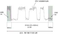
图4A示出了高音频(例如1,042Hz或1,050Hz)AFLC载波或“纹波”信号施加在50Hz或60Hz电源AC电压上;Figure 4A shows a high-frequency (eg, 1,042Hz or 1,050Hz) AFLC carrier or "ripple" signal applied to a 50Hz or 60Hz mains AC voltage;
图4B示出了传统的用标准的十进制数字字段编码的十进制AFLC载波或“纹波”信号的数字编码的细节;Figure 4B shows details of the digital encoding of a conventional decimal AFLC carrier or "ripple" signal encoded with a standard decimal number field;
图5描绘了安装在需要功率因数校正的典型设施的标准传统开关电容器PFC系统的简化电路图;Figure 5 depicts a simplified circuit diagram of a standard conventional switched capacitor PFC system installed in a typical facility requiring power factor correction;
图6A描绘了根据本发明的实施例的具有电网音频或AFLC信号处理电路的PFC电容器子系统的简化电路图;6A depicts a simplified circuit diagram of a PFC capacitor subsystem with grid audio or AFLC signal processing circuitry in accordance with an embodiment of the present invention;
图6B描绘了PFC控制器的简化电路图,其中添加了图6A所示的PFC电容器子系统的AFLC信号处理电路;Figure 6B depicts a simplified circuit diagram of a PFC controller with the AFLC signal processing circuitry of the PFC capacitor subsystem shown in Figure 6A added;
图6C示出了根据本发明另一实施例的在带有AFLC信号处理电路的PFC电容器子系统中的AFLC信号检测电路;6C shows an AFLC signal detection circuit in a PFC capacitor subsystem with an AFLC signal processing circuit according to another embodiment of the present invention;
图7示出了根据本发明的实施例的用标准十进制数字字段编码的传统的十进制AFLC载波或“纹波”信号的数字编码的细节以及引入AFLC阻抗的时序细节;Figure 7 shows details of the digital encoding of a conventional decimal AFLC carrier or "ripple" signal encoded with a standard decimal number field and the timing details of the introduction of the AFLC impedance, according to an embodiment of the present invention;
图8A示出了传统的不仅校正电网基频处的PF而且校正更高频谐波的应用中的传统有源滤波器(APF)的框图;Figure 8A shows a block diagram of a conventional active filter (APF) in a conventional application to correct not only the PF at the grid fundamental frequency but also higher frequency harmonics;
图8B示出了根据本发明一个实施方式的用于校正在输电干线基频和更高频谐波处的PF的系统的框图,其中是通过使用低功率损耗、低热耗散及高效的无源PFC电容器与低功耗的APF来实现该校正;以及Figure 8B shows a block diagram of a system for correcting PF at the fundamental frequency and higher frequency harmonics of a power mains, according to one embodiment of the invention, by using low power loss, low heat dissipation, and efficient passive PFC capacitors and low-power APF to achieve this correction; and
图8C示出了图8B所示的系统中基频和更高频谐波的电流幅度与频率的关系图。Figure 8C shows a graph of current amplitude versus frequency for the fundamental frequency and higher frequency harmonics in the system shown in Figure 8B.
具体实施方式Detailed ways
下面的描述将阐述用于在AC电网中校正功率因数(PF)和谐波以及在存在PFC设备的情况下允许AFLC网络负载平衡工作等等的方法、系统和设备的优选示例。对于本领域技术人员而言,显而易见的是,在不脱离本申请的范围和精神的情况下,可以作出修改,包括添加和/或替换。虽然为了避免模糊本申请,可以省略具体细节,但是,本申请记载了为允许本领域技术人员在不需要过度实验的情况下实施本文中的教导。The following description will set forth preferred examples of methods, systems and devices for correcting power factor (PF) and harmonics in an AC grid, allowing AFLC network load balancing operation in the presence of PFC devices, and the like. It will be apparent to those skilled in the art that modifications, including additions and/or substitutions, can be made without departing from the scope and spirit of the application. Although specific details may be omitted in order to avoid obscuring the application, this disclosure is presented to allow one skilled in the art to practice the teachings herein without undue experimentation.
众所周知,当电感负载连接到AC电网时,由于电感负载的电抗,电流波形开始滞后于电压波形。另一方面,当电容负载连接到电网时,由于电容负载的电抗,电流波形开始超前电压波形。对于电感负载和电容负载二者而言,电压和电流之间的相位差与PF有关,并且该相位差是由滞后或超前的无功功率KVAR来估量。当电压和电流在相位上校正对齐时,电网的PF等于1(PF=1.0),且KVAR=0。随着电感负载的增加,由于电流波形开始滞后于电压波形,PF降到1.0以下,且滞后的KVAR增加;而当电容负载增加时,类似地,由于电流波形开始超前电压波形,PF降到1.0以下,且超前的KVAR增加。PF的减少、或者滞后或超前的KVAR的增加,会导致在电力成本和违约金方面的严重后果,可能会被征税。而且,由于补偿性的无功功率,无论滞后或超前,是一定会产生、传输并提供给负载,因此,KVAR增加了发电成本和配电成本。例如,低于阈值的功率因数和/或高于阈值的无功功率KVAR将按照供电商和/或配电网运营商的判断而结算给用户。在一些情况下,甚至在PF<0.9时,最终消费者承担了重税和额外的费用。It is well known that when an inductive load is connected to the AC grid, the current waveform starts to lag the voltage waveform due to the reactance of the inductive load. On the other hand, when a capacitive load is connected to the grid, the current waveform starts to lead the voltage waveform due to the reactance of the capacitive load. For both inductive and capacitive loads, the phase difference between voltage and current is related to PF, and this phase difference is estimated by lagging or leading reactive power KVAR. When the voltage and current are aligned in phase, the PF of the grid is equal to 1 (PF=1.0), and KVAR=0. As the inductive load increases, PF drops below 1.0 as the current waveform begins to lag the voltage waveform, and the lagging KVAR increases; while as the capacitive load increases, PF similarly drops to 1.0 as the current waveform begins to lead the voltage waveform Below, and ahead of, KVAR increases. A reduction in PF, or an increase in lagging or leading KVAR, can have serious consequences in terms of electricity costs and liquidated damages, which may be taxed. Moreover, since compensating reactive power, whether lagging or leading, must be generated, transmitted, and supplied to the load, KVAR increases generation and distribution costs. For example, the power factor below the threshold and/or the reactive power KVAR above the threshold will be settled to the user according to the judgment of the power supplier and/or distribution network operator. In some cases, even when PF < 0.9, the final consumer bears heavy taxes and additional costs.
一般而言,配电网中的大多数类型的负载是电感负载,其会导致滞后的PF或滞后的无功功率KVAR。因此,常见的做法是:增加无源电能质量补偿设备,将PF校正回到接近1.0,消除或最小化滞后的无功功率KVAR,以及恢复电能质量;其中无源电能质量补偿设备依靠于接通或启动(switch ON)整个电网相位中的各种值的线性PFC电容器块,以补偿电感负载。然而,这些传统的线性无源电能质量补偿设备的问题在于它们容易过度补偿。Generally speaking, most types of loads in the distribution network are inductive loads, which cause a lagging PF or a lagging reactive power KVAR. Therefore, the common practice is to: add passive power quality compensation equipment, correct PF back to close to 1.0, eliminate or minimize the lagging reactive power KVAR, and restore power quality; where passive power quality compensation equipment relies on switching on Or switch ON blocks of linear PFC capacitors of various values throughout the grid phases to compensate inductive loads. However, the problem with these traditional linear passive power quality compensation devices is that they are prone to overcompensation.
这些传统的线性无源电能质量补偿设备的操作通常如下:首先,测量PF或所需量的超前无功功率KVAR;其次,通过各种方式,例如通过从具有待选择的电容的最小值和最大值的查找表导出的方式,计算最小化或消除滞后无功功率KVAR所需的电容量;最后通过包括继电器、接触器、半导体开关器件及其组合在内的一或多种装置,将计算所得的量的电容接通或启动。此外,电容器块的常规使用是以线性阵列而布置。例如,对于100KVAR PFC子系统,通常有八个12.5KVAR或四个25KVAR的电容器块,并且PFC控制器以线性步距的方式,例如按12.5KVAR或25KVAR的步距,接通或启动一些这样的电容器块。PFC控制器通常选择足够的电容器来驱动PF至最接近1.0,而不管它是否过度补偿,并且是否会将超前的KVAR置于电网。The operation of these traditional linear passive power quality compensation devices is usually as follows: firstly, measure PF or the required amount of leading reactive power KVAR; Calculate the capacitance required to minimize or eliminate the lagging reactive power KVAR by deriving the look-up table of the value; finally, use the calculated capacitance through one or more devices including relays, contactors, semiconductor switching devices and their combinations The amount of capacitance to turn on or start. Furthermore, conventional use of capacitor blocks is arranged in a linear array. For example, for a 100KVAR PFC subsystem, there are typically eight 12.5KVAR or four 25KVAR capacitor blocks, and the PFC controller switches on or starts up some of these blocks in linear steps, such as 12.5KVAR or 25KVAR capacitor block. A PFC controller typically chooses enough capacitors to drive the PF to the nearest 1.0, regardless of whether it overcompensates and puts leading KVAR on the grid.
以往,由于配电网通常因连接到其的变压器、电动机、荧光镇流器等等而滞后或感应,所以电力行业并不关心超前KVAR的过度补偿,没有因此而处罚使用者。然而,随着现在日益复杂的电子负载被添加到电网中,就像关注滞后KVAR那样,人们越来越关注超前KVAR的过度补偿问题,供电商和配电网运营商开始惩罚造成低PF的使用者,无论是超前(电容负载)或是滞后(电感负载)。In the past, the utility industry was not concerned with overcompensating leading KVARs and did not penalize users for this because the distribution grid was often lagging or inductive due to the transformers, motors, fluorescent ballasts, etc. connected to it. However, with now increasingly complex electronic loads being added to the grid, there is growing concern about overcompensation of leading KVAR as much as lagging KVAR, and suppliers and distribution network operators are beginning to penalize the use of low PF Or, whether it is leading (capacitive loads) or lagging (inductive loads).
过去不仅认为使用无源线路PFC电容器对消除滞后无功功率KVAR是有效的,而且可以容忍电网中存在尽量小量的超前无功功率KVAR或过度补偿。而如今,在越来越多的管辖区域中,增加任何程度超前无功功率或过度补偿的增加也将受到惩罚,因为它仍然降低PF,并且不可避免地产生、传输及提供额外的无功功率KVAR给KVAR负载。In the past, it was considered that the use of passive line PFC capacitors was not only effective in eliminating lagging reactive power KVAR, but also tolerated a small amount of leading reactive power KVAR or overcompensation in the grid. Today, however, in a growing number of jurisdictions, any increase in lead reactive power or overcompensation is also penalized as it still reduces PF and inevitably generates, transmits and supplies additional reactive power Kvar gives Kvar load.
传统上,线性PFC电容器块与用于计算所需超前KVAR以补偿滞后KVAR负载的补偿算法一起使用,以实现接近1.0的PF。线性PFC电容器块根据计算而接通或启动,但通常只能达到尽可能接近1.0的PF。这是在没有考虑过度补偿的情况下完成的。由于立法开始改变政策,并且开始禁止过度补偿超前KVAR,于是,由于传统上使用线性PFC电容器块以达到接近1.0的PF以及实现零过度补偿超前KVAR是非常困难的(即使并非不可能),因此会出现问题。Traditionally, linear PFC capacitor blocks are used with compensation algorithms to calculate the required leading KVAR to compensate for lagging KVAR loads to achieve a PF close to 1.0. Linear PFC capacitor blocks are switched on or turned on based on calculations, but typically only achieve a PF as close to 1.0 as possible. This is done without taking into account overcompensation. As legislation began to change policy and began to prohibit overcompensation leading KVAR, then, since it is very difficult (if not impossible) to achieve a PF close to 1.0 and achieve zero overcompensation leading KVAR traditionally using linear PFC capacitor blocks, it will problem appear.
美国专利No.9,712,048公开了一种使用数字PFC电容器阵列的无源功率因数补偿的方法。参考图1。如图1清楚地示出那样,由于“Y轴”的PF相对于“X轴”的KVAR是趋于渐近的,所以通过使用以可寻址数字阵列方式布置的线性PFC电容器,可以执行PF校正,其中,较高值的PFC电容器能在PF校正中实现“粗步距”(“coarse steps”)增量,而较低值的PFC电容器能在PF校正中实现“细步距”(“fine steps”)。'048专利还公开了PFC电容器按相关值渐减的方式布置;因此,“细步距”或小的KVAR增量能够推动PF并使其保持在接近1.0而不过度补偿。换句话说,在不降低电能质量的情况下,可以在电网中正确且最优地实现最小或零无功功率KVAR。US Patent No. 9,712,048 discloses a method of passive power factor compensation using a digital PFC capacitor array. Refer to Figure 1. As Figure 1 clearly shows, since the PF of the "Y-axis" tends to be asymptotic with respect to the KVAR of the "X-axis", by using linear PFC capacitors arranged in an addressable digital array, it is possible to perform PF correction, where higher value PFC capacitors enable “coarse steps” increments in PF correction and lower value PFC capacitors enable “fine steps” (“coarse steps”) in PF correction fine steps"). The '048 patent also discloses that the PFC capacitors are arranged in such a way that the relative value decreases; thus, "fine steps" or small KVAR increments can push the PF and keep it close to 1.0 without overcompensating. In other words, minimum or zero reactive power KVAR can be correctly and optimally achieved in the grid without degrading the power quality.
本领域普通技术人员可以理解,使用从大到小布置的不同范围电容值的PFC电容器,其不一定与'048专利中公开的数字阵列结构完全相同,仍然可以实现类似上述数字阵列的功能。较大的PFC电容器随“粗步距”而接通或启动,较小的PFC电容器随“细步距”而接通或启动。因此,通过将PFC电容器的步距从“粗步距”切换到(或激活为)“细步距”电容器,可以实现类似的PF补偿性能,此时PF接近1.0而没有过度补偿。Those of ordinary skill in the art can understand that using PFC capacitors with different ranges of capacitance arranged from large to small, which may not be exactly the same as the digital array structure disclosed in the '048 patent, can still achieve functions similar to the above digital array. Larger PFC capacitors are turned on or started with "coarse steps" and smaller PFC capacitors are turned on or started with "fine steps". Thus, similar PF compensation performance can be achieved by switching the step size of the PFC capacitor from "coarse step" to (or activated as) a "fine step" capacitor, where the PF is close to 1.0 without overcompensation.
参考图2。根据本发明的一个实施方式,本实施方式对'048专利中公开的数字PFC电容器阵列中传统线性PFC电容器块的使用作出了重大改进。本实施方式提供了一种PFC电容器子系统,其包括数字PFC电容器阵列、一或多个线性电容器阵列以及PFC控制器;其中,数字PFC电容器阵列为例如'048专利的一个实施方式中公开的数字PFC电容器阵列;每一个线性电容器阵列包括一或多个线性PFC电容器。数字PFC电容器阵列和一或多个线性电容器阵列由PFC控制器控制,并以模块方式布置在PFC电容器子系统中。Refer to Figure 2. According to one embodiment of the present invention, this embodiment provides a significant improvement over the use of conventional linear PFC capacitor banks in the digital PFC capacitor array disclosed in the '048 patent. This embodiment provides a PFC capacitor subsystem, which includes a digital PFC capacitor array, one or more linear capacitor arrays, and a PFC controller; PFC capacitor arrays; each linear capacitor array includes one or more linear PFC capacitors. The digital PFC capacitor array and one or more linear capacitor arrays are controlled by the PFC controller and arranged in a modular manner in the PFC capacitor subsystem.
图2示出了PFC电容器子系统的示例性实施例。模块1是数字PFC电容器阵列,模块2、……、n是线性电容器阵列,PFC控制器提供模块间的切换控制。由于模块1依赖于其内部的PFC电容器的高速半导体开关,因此,与其他线性电容器阵列模块相比,其产生并耗散更多的热。数字PFC电容器阵列的制作成本也比一个线性电容器阵列要昂贵。然而,由于PFC电容器子系统包括更多的线性电容器阵列模块,PFC电容器子系统的整体热分布和成本可以接近于具有相当容量的纯粹的线性PFC电容器结构的整体热分布和成本。图2所示的PFC电容器子系统,通过使用相对较大的线性PFC电容器阵列模块,能够实现“粗步距”调整(或大的KVAR增量);以及通过使用数字PFC电容器阵列模块,能够实现“细步距”调整(或小的KVAR增量),以促使PF尽可能地接近1.0,而不会过度补偿以及不会添加到电网的超前KVAR。Figure 2 illustrates an exemplary embodiment of a PFC capacitor subsystem.
根据本发明的PFC电容器子系统,其容许总的KVAR校正,甚至还能降低峰值需求降低,并且子系统内损失尽可能少。根据另一实施方式,通过包含有源滤波器(APF),PFC电容器子系统对负载的变化提供三级响应。如果负载变化,微秒级响应的APF作出响应,此为第一级KVAR补偿。该APF的微秒级响应确保了瞬变或快速上升时间KVAR的补偿。将APF作为第一级响应,还降低了电压波动性,允许更稳定电流流入电网。一旦第二级的毫秒级响应的数字PFC电容器阵列模块开启,APF将补偿后的KVAR传输到更高效的数字PFC电容器阵列,最后传输到线性PFC电容器阵列模块。因此,PFC电容器子系统模块包括较慢但更高效的线性PFC电容器阵列、数字PFC电容器阵列、以及较快但效率较低的APF的组合。对于具有高灵敏度峰值需求及低电压波动需求的电网而言,这种高效且快速响应的方法特别有利。According to the PFC capacitor subsystem of the present invention, it allows a total KVAR correction and even lower peak demand reduction with as few losses as possible within the subsystem. According to another embodiment, the PFC capacitor subsystem provides a tertiary response to load changes by including an active filter (APF). If the load changes, the microsecond response APF responds, which is the first level of KVAR compensation. The microsecond response of this APF ensures compensation of transients or fast rise time KVARs. Using the APF as the first level of response also reduces voltage volatility, allowing more stable current flow into the grid. Once the second-stage digital PFC capacitor array module with millisecond response is turned on, the APF transmits the compensated KVAR to the more efficient digital PFC capacitor array, and finally to the linear PFC capacitor array module. Thus, the PFC capacitor subsystem module includes a combination of a slower but more efficient linear PFC capacitor array, a digital PFC capacitor array, and a faster but less efficient APF. This efficient and fast-response approach is particularly beneficial for grids with high sensitivity to peak demand and low voltage fluctuations.
而且,本领域普通技术人员应该很好地理解到,以数字阵列方式布置的PFC电容器和以一或多个线性阵列方式布置的另外的PFC电容器可以组合起来运作,不需要以分离的模块布置,如图2所示的示例性实施例所示。控制器和PFC电容器可以有各种不同的机械结构或组装,包括集成的单个或多个单独的组装。然而,PFC设备的这些不同呈现方式不以任何方式否定如下原理的创造性或偏离如下原理的精神,即:采用以数字阵列方式布置的PFC电容器与以一或多个线性阵列方式布置的另外PFC电容器,将它们组合起来运作,且它们都受控于PFC控制器。Moreover, it should be well understood by those of ordinary skill in the art that PFC capacitors arranged in a digital array and additional PFC capacitors arranged in one or more linear arrays can be combined to operate without having to be arranged in separate modules, This is shown in the exemplary embodiment shown in FIG. 2 . The controller and PFC capacitors can have various mechanical configurations or assemblies, including an integrated single or multiple individual assemblies. However, these different presentations of PFC devices do not in any way negate the inventiveness of or depart from the spirit of the principle of employing PFC capacitors arranged in a digital array with additional PFC capacitors arranged in one or more linear arrays , to operate them in combination, and they are all controlled by the PFC controller.
而且,为了实现非常快(在毫秒内)的KVAR校正,电容器阵列中的每个PFC电容器的快速切换由一或多种切换算法控制,这些算法由PFC控制器中的一或多个微控制器和/或处理器执行。根据一个实施方式,PFC控制器封装为一个模块,并与PFC电容器子系统集成。在另一个实施方式中,PFC控制器是与PFC电容器子系统分离的独立组件。根据一个实施方式,当使用快速开关时,使用线路连接高压AC开关半导体来进行PFC电容器的快速切换,线路连接高压AC开关半导体包括但不限于三端双向交流开关、背对背可控硅晶闸管(SCR’s)、整流桥配置中的可控硅晶闸管、可关断晶闸管(GTO’s)、背对背金属氧化半导体场效应晶体管(MOS FET’s)、绝缘栅双极性晶体管(IGBT’s)、双极结晶体管(BJT’s)。在将PF电容器快速切换进出电网的高AC电压线路时,这些电容器开关半导体完全不受高的破坏性浪涌电流的影响,这是至关重要的。Also, in order to achieve very fast (within milliseconds) KVAR correction, the fast switching of each PFC capacitor in the capacitor array is controlled by one or more switching algorithms, which are controlled by one or more microcontrollers in the PFC controller and/or processor execution. According to one embodiment, the PFC controller is packaged as a module and integrated with the PFC capacitor subsystem. In another embodiment, the PFC controller is a separate component from the PFC capacitor subsystem. According to one embodiment, when fast switching is used, fast switching of the PFC capacitor is performed using line connected high voltage AC switching semiconductors including but not limited to triacs, back-to-back silicon controlled thyristors (SCR's) , SCR thyristors, turn-off thyristors (GTO's), back-to-back metal oxide semiconductor field effect transistors (MOS FET's), insulated gate bipolar transistors (IGBT's), bipolar junction transistors (BJT's) in rectifier bridge configuration. It is critical that these capacitor switching semiconductors are completely immune to high damaging inrush currents when rapidly switching PF capacitors into and out of the grid's high AC voltage lines.
参考图3A。根据一个优选实施方式,提供了一种PFC电容器半导体切换方法,其依赖于对快速开关元件两端的电压的检测。在该方法中,使用零电压检测电路来持续地追踪开关两端的电压。零电压检测的信息被传送到微控制器或处理器,然后微控制器或处理器可以产生必要的驱动信号来开启开关元件。例如,在50Hz的交流电网中,每10毫秒进行一次零电压检测,并且开关元件可以在零电压检测那些时间期间进行切换,从而得到近乎实时的切换。微控制器或处理器还可以配置为通过学习零电压检测的出现率来学习零电压检测的模式,从而,藉由预测下一次零电压检测,并且在接近绝对零电压的可接受电压电平处提前或定时驱动信号来接通开关元件,可以补偿电路中的任何延迟。Refer to Figure 3A. According to a preferred embodiment, there is provided a PFC capacitor semiconductor switching method which relies on sensing the voltage across a fast switching element. In this method, a zero voltage detection circuit is used to continuously track the voltage across the switch. The information of the zero voltage detection is communicated to the microcontroller or processor, which can then generate the necessary drive signals to turn on the switching elements. For example, in a 50 Hz AC grid, zero voltage detection occurs every 10 milliseconds, and switching elements can switch during those times of zero voltage detection, resulting in near real-time switching. The microcontroller or processor can also be configured to learn the pattern of zero voltage detection by learning the frequency of occurrence of zero voltage detection, thereby, by predicting the next zero voltage detection, and at an acceptable voltage level close to absolute zero voltage Driving the signal in advance or timing it to turn on the switching element compensates for any delay in the circuit.
此外,在这种零电压切换方法中,当PFC电容器在零电压处接通时,在其放电状态期间,PFC电容器不会产生浪涌电流,因此PFC电容器两端不会产生差分电压。切换电流将导致类似电阻的负载,从而减小图3B所示的开关元件中的电流浪涌应力。参考图3B。PFC控制器读取零电压信号(底部的波形),并且,在PFC控制器要求PFC电容在图形的第四象限内接通时,PFC控制器等待零电压检测并驱动开关元件在零电压处切换,从而不产生浪涌电流,就像电流信号(中间的波形)给出的那样。In addition, in this zero-voltage switching method, when the PFC capacitor is switched on at zero voltage, during its discharge state, the PFC capacitor does not generate inrush current, so no differential voltage is generated across the PFC capacitor. Switching the current will result in a resistive like load, reducing the current surge stress in the switching element shown in Figure 3B. Refer to Figure 3B. The PFC controller reads the zero voltage signal (bottom waveform) and, when the PFC controller asks the PFC capacitor to turn on in the fourth quadrant of the graph, the PFC controller waits for zero voltage detection and drives the switching element to switch at zero voltage , so that there is no inrush current, as given by the current signal (waveform in the middle).
参考图3C示出的PFC电容器半导体切换方法的替换实施方式,其是一种利用电压分压器的PFC电容器的切换方法。在这种方法中,在零电压切换时,PFC电容器会因其两端的任何电压而放电。对于串联电路,每个元件两端的电压降总和为零,当PFC电容器因任何保持电压而放电时,开关元件两端的电压与输入端电压相同。然后可以将零电压检测电路置于输电干线的输入。零电压检测信号在之后将由PFC控制器处理。一旦分压电路将PFC电容器两端的所有电压放电,在从零电压检测电路接收到零电压检测信号时,PFC控制器就可以驱动开关元件转为接通状态。Referring to FIG. 3C , an alternative embodiment of the PFC capacitor semiconductor switching method is shown, which is a PFC capacitor switching method using a voltage divider. In this method, at zero voltage switching, the PFC capacitor is discharged by any voltage across it. For a series circuit, the voltage drops across each element sum to zero, and when the PFC capacitor is discharged from any holding voltage, the voltage across the switching elements is the same as the voltage at the input. A zero voltage detection circuit can then be placed at the input of the mains. The zero voltage detection signal will be processed later by the PFC controller. Once the voltage divider circuit discharges all the voltage across the PFC capacitor, the PFC controller can drive the switching element to turn on when receiving a zero voltage detection signal from the zero voltage detection circuit.
根据各种实施方式,PFC电容器子系统可通过添加任意数量的模块来扩展,以设计出大的KVAR可校正产品。这样的PFC电容器子系统可以具有一或多个(但通常为一个)数字PFC电容器阵列模块,以及多个较低成本的线性PFC电容器阵列模块。在200KVAR校正的PFC电容器子系统的一个示例性实施例中,PFC电容器子系统包括四个50KVAR校正模块,其中一个模块是如'048专利中公开的数字PFC电容器阵列,其余的为较低成本的线性PFC电容器阵列。作为非限制性示例,三个线性PFC电容器阵列中的每一个可以包括两个25KVAR电容器块。为实现相同的零过度补偿或低的过度补偿性能,通过将数字PFC电容器阵列与三个较低成本线性PFC电容器阵列相结合,PFC电容器子系统的整体成本比类似的全部使用数字PFC电容器阵列的KVAR校正产品要低。另外,线性PFC电容器阵列的较少发热与数字PFC电容器阵列的较高热耗散相抵后,PFC电容器子系统的热分布曲线比类似的全部使用数字PFC电容器的KVAR校正产品的热分布曲线要低。这样反过来降低了组件冷却要求,并且提高了PFC电容器子系统的可靠性以及延长了其使用寿命。According to various embodiments, the PFC capacitor subsystem can be expanded by adding any number of modules to design large KVAR correctable products. Such a PFC capacitor subsystem may have one or more (but typically one) digital PFC capacitor array blocks, as well as multiple lower cost linear PFC capacitor array blocks. In one exemplary embodiment of a 200KVAR corrected PFC capacitor subsystem, the PFC capacitor subsystem includes four 50KVAR corrected modules, one of which is a digital PFC capacitor array as disclosed in the '048 patent, and the rest are lower cost Linear PFC capacitor array. As a non-limiting example, each of the three linear PFC capacitor arrays may include two 25KVAR capacitor banks. To achieve the same zero or low overcompensation performance, by combining a digital PFC capacitor array with three lower cost linear PFC capacitor arrays, the overall cost of the PFC capacitor subsystem is similar to that of using all digital PFC capacitor arrays The KVAR corrected product should be lower. In addition, the less heat generated by the linear PFC capacitor array is offset by the higher heat dissipation of the digital PFC capacitor array, the thermal profile of the PFC capacitor subsystem is lower than that of a similar KVAR corrected product using all digital PFC capacitors. This in turn reduces component cooling requirements and increases the reliability and lifetime of the PFC capacitor subsystem.
图4A示出了高音频(例如1,042Hz或1,050Hz)AFLC载波或“纹波”信号施加在50Hz或60Hz电源交流电压上。例如,在澳大利亚,提供的标准交流电源电压为230VAC和50Hz。在AFLC继电器上的AFLC信号为该电压的大约2-3%。在AFLC继电器上的典型的AFLC信号的幅值需要在大约5-6伏的水平,然后可将该AFLC信号解调和解码用于控制它们的降低负载操作的指令数据。Figure 4A shows a high frequency (eg 1,042Hz or 1,050Hz) AFLC carrier or "ripple" signal applied to a 50Hz or 60Hz mains AC voltage. For example, in Australia, the standard AC mains voltage provided is 230VAC and 50Hz. The AFLC signal on the AFLC relay is about 2-3% of this voltage. A typical AFLC signal on an AFLC relay needs to be at a level of about 5-6 volts in magnitude, which can then be demodulated and decoded to command data for controlling their load-reduced operation.
图4B示出了用标准的十进制数字字编码的传统的十进制AFLC载波或“纹波”信号的数字编码的细节。通过数字字指示响应于AFLC载波或“纹波”信号的AFLC继电器连接或断开安装有AFLC继电器的设备中的特定电气负载。将本发明应用于其它AFLC频率和系统对本领域普通技术人员应当是显而易见的。Figure 4B shows details of the digital encoding of a conventional decimal AFLC carrier or "ripple" signal encoded with standard decimal digital words. The AFLC relay responding to the AFLC carrier or "ripple" signal is indicated by a digital word to connect or disconnect a specific electrical load in the equipment in which the AFLC relay is installed. It should be apparent to one of ordinary skill in the art that the present invention is applicable to other AFLC frequencies and systems.
图5描绘了安装在需要功率因数校正的典型设施中的标准传统开关电容器PFC电容器子系统200的简化电路图。功率因数校正通过PFC控制器202经由电流转换器(CT)201来测量电源负载电流波形,并且通过各种方式来测量电源负载电压波形。PFC控制器202然后测量电源负载电压和电流之间的相移,并且基于测量的相移,确定并控制PFC电容器开关203的开关顺序以获得最接近的PFC电容值以校正相移。FIG. 5 depicts a simplified circuit diagram of a standard conventional switched capacitor
跨接在电源上的大型PFC电容器204使AFLC系统出现问题。PFC电容器204的存在对于例如1,042Hz和1,050Hz的较高AFLC频率呈现非常低的阻抗。这反过来又将高频AFLC信号旁路到中性和/或短路AFLC信号,从而降低AFLC信号的幅度,足以使得AFLC继电器的运行变得不可靠,并导致AFLC网络负载平衡的故障。A
仍然参考图5。为了减轻这个问题,一个解决方案是将AFLC阻塞无源滤波器205安装在PFC电容器子系统200的外部或内部。AFLC阻塞无源滤波器205通常安装为调谐到特定配电网络电源中使用的特定AFLC频率的并联电路。AFLC阻塞无源滤波器205在电源频率(例如50Hz或60Hz)处呈现低阻抗,但在AFLC频率(例如1,042Hz或1,050Hz)处呈现高阻抗。一般来说,AFLC阻塞无源滤波器是体积较大,重量较重,并且可以在电气系统中产生谐波共振。此外,AFLC阻塞无源滤波器通常比图5所示的那些复杂得多,并具有额外的过滤元件,为PFC设备和/或装置增加了显著的尺寸,重量和成本。Still referring to FIG. 5 . To alleviate this problem, one solution is to install the AFLC blocking
参考图6A。根据各种实施方式,前述PFC电容器子系统可以包含AFLC检测和阻抗控制电路。AFLC电流信号取自电网线路上的电流互感器。根据一个实施方式,AFLC检测和阻抗控制电路读取并处理来自电流互感器的AFLC电流信号以及线路上的AFLC电压信号,并切换阻抗电阻器的接通与断开。在优选实施方式中,可以用低热耗散的电容器、电感器或其组合来替代高热耗散的阻抗电阻器。Refer to Figure 6A. According to various implementations, the aforementioned PFC capacitor subsystem may include AFLC detection and impedance control circuitry. The AFLC current signal is taken from the current transformer on the grid line. According to one embodiment, the AFLC detection and impedance control circuit reads and processes the AFLC current signal from the current transformer and the AFLC voltage signal on the line, and switches the impedance resistor on and off. In a preferred embodiment, the high heat dissipation impedance resistors may be replaced with low heat dissipation capacitors, inductors or combinations thereof.
在另一个实施方式中,完全去除了包括电阻器、电容器、电感器或其任何组合的阻抗元件。由以下方式替代阻抗元件的功能:当通过电流互感器首先检测到音频或AFLC电流信号的那一刻,快速断开(或分离)PFC电容器,并且在音频或AFLC电压存在的整个期间,PFC电容器保持为断开状态。In another embodiment, impedance elements including resistors, capacitors, inductors, or any combination thereof are completely removed. The function of the impedance element is replaced by rapidly disconnecting (or detaching) the PFC capacitor at the moment the audio or AFLC current signal is first detected through the current transformer, and the PFC capacitor remains is disconnected.
在又一个实施方式中,当通过电流互感器首先检测到音频或AFLC电流信号时,以迅速的步距(例如,以毫秒的间隔)将当前为接通或接合的PFC电容器的电容器逐个断开,直至正被测量的音频或AFLC电压上升到恰好或刚好超过电网中的最小电平,但仍足够处于音频或AFLC规格内。例如,对于标准的传统AFLC系统,典型的AFLC频率计所能接受的最低电压电平为1伏RMS,因此允许接通最大数量的PFC电容器,从而音频或AFLC电压电平为至少1.5伏RMS,这是适当的。在又一个替代实施方式中,当通过电流互感器首先检测到音频或AFLC电流信号时,将当前为接通或接合的PFC电容器的电容器完全断开,之后以迅速的步距(例如,以毫秒的间隔)逐个接通,直至正被测量的音频或AFLC电压恰好或刚好低于电网中的最小电平,但仍足够处于音频或AFLC规格内。In yet another embodiment, when an audio or AFLC current signal is first detected by a current transformer, the capacitors that are currently on or engaged PFC capacitors are individually disconnected in rapid steps (e.g., at millisecond intervals) , until the audio or AFLC voltage being measured rises to just or just above the minimum level in the grid, but still sufficiently within audio or AFLC specifications. For example, for a standard legacy AFLC system, the lowest voltage level acceptable to a typical AFLC frequency meter is 1 volt RMS, thus allowing a maximum number of PFC capacitors to be switched on, resulting in an audio or AFLC voltage level of at least 1.5 volts RMS, This is appropriate. In yet another alternative embodiment, when an audio or AFLC current signal is first detected by a current transformer, the capacitor that is currently an on or engaged PFC capacitor is completely disconnected, and thereafter in rapid steps (e.g., in milliseconds) intervals) until the audio or AFLC voltage being measured is at or just below the minimum level in the grid, but still sufficiently within audio or AFLC specifications.
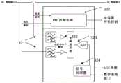
仍然参考图6A。在本发明的一实施例中,AFLC信号处理电子电路包括添加到已经在PFC电容器子系统300中使用的电子电路中的电子元件。AFLC信号处理电子电路可以利用现有的CT 301或用于测量电源负载电流波形的单独的CT。调谐到AFLC频率的第一组额外的电子电路被添加到PFC控制器302,以检测AFLC载波或“纹波”信号,并且测量电源负载电压和电流之间的相移。第二组附加电子电路被添加到PFC控制器302以驱动AFLC阻抗开关306。还添加了与所述PFC电容器304串联的AFLC阻抗305。Still referring to FIG. 6A . In an embodiment of the invention, the AFLC signal processing electronics include electronic components added to the electronics already used in the
在该实施例中,AFLC阻抗开关306是机电继电器或接触器;并且AFLC阻抗305是一个简单的电阻(R),其具有足够的阻值,以提供允许AFLC信号旁路PFC电容器子系统且与PFC电容串联的显著阻抗。当在配电网络中出现AFLC信号时,附加的AFLC信号处理电子电路检测AFLC载波或“纹波”信号,并快速将AFLC阻抗305接入,解除PFC电容器304一段时间,以允许完整的AFLC信号通过。根据本实施例的PFC电容器子系统300的AFLC信号处理,相对于将电源中的所有或大部分PFC电容器切出和接入到电路的情况,对电源电压造成最低的干扰。In this embodiment, the
可以使用各种检测和定时装置以便使得完整的AFLC信号完全传输到AFLC继电器。例如,一旦首先检测到AFLC信号的存在,则在一固定的时间段内保持AFLC阻抗305的接入和不间断的检测。要注意的是,AFLC信号处理电子电路必须快速运行。如图4B所示,标准AFLC信号的数字分量具有600毫秒宽的起始脉冲。AFLC继电器必须接收600毫秒的起始脉冲的大部分才能可靠地运行。Various detection and timing arrangements may be used in order to allow complete transmission of the complete AFLC signal to the AFLC relay. For example, once the presence of the AFLC signal is first detected, the AFLC impedance 305 remains switched on and continuously detected for a fixed period of time. It is to be noted that the AFLC signal processing electronics must operate fast. As shown in Figure 4B, the digital component of the standard AFLC signal has a 600 millisecond wide start pulse. The AFLC relay must receive most of the 600 ms initial pulse to operate reliably.
图6B更详细地示出了PFC控制器302。CT 301输出端的电源负载电流波形由PFC控制电路和PFC控制器302中的AFLC信号处理电路并行地接收。高频AFLC载波或“纹波”信号分量首先被放大器311放大。放大的信号被传送到被调谐到特定AFLC固定载波或“纹波”信号频率的调谐滤波器312。然后将调谐滤波器312的输出传递到调谐锁相环(PLL)313以抑制信号噪声。PLL 313的输出指示AFLC信号的存在(或不存在),并且由AFLC阻抗开关控制电子电路314用于在存在AFLC信号的情况下快速打开AFLC阻抗开关306,从而引入AFLC阻抗305与PFC电容器304串联连接,阻塞来自PFC电容器子系统的AFLC信号。Figure 6B shows the
一旦AFLC信号通过,在没有AFLC信号的情况下,AFLC阻抗开关控制电子电路314将默认关闭AFLC阻抗开关306,从而旁路AFLC阻抗305。Once the AFLC signal is passed, in the absence of an AFLC signal, the AFLC impedance
图6C示出了根据本发明另一实施例的具有AFLC信号处理电路的PFC电容器子系统300中的AFLC信号检测电路。在该实施例中,模拟电网电压和电网电流信号分别被馈送到PFC控制器302中的PFC控制电路和AFLC信号处理电路。电压和电流信号被两个高通滤波器321滤波。这些高通滤波器是为了在数字处理之前衰减基本电源线路的频率分量以提高高频AFLC信号的动态范围。高通滤波器还提供DC电平移位和增益设置,使得可能的信号幅度的最大值在AFLC信号检测电路的模拟动态范围能力内。经过滤波的电压和电流信号随后由多路复用器322选择。所选择的电压和电流信号由模数(A/D)转换器323转换成数字值。数字信号处理器324以周期性的方式处理随时间变化的电压和电流波形,其中电压和电流波形被采样并变换到频域中以识别AFLC信号的特定频率分量。在实际应用中,复用器,A/D转换器和信号处理器可以是集成在微处理器中的功能块。FIG. 6C shows an AFLC signal detection circuit in a
尽管在此仅描述了单相电系统,但是本发明的原理可以应用于其他AC频率和多相AC系统,例如常见的三相电系统。Although only a single-phase electrical system is described here, the principles of the invention can be applied to other AC frequency and multi-phase AC systems, such as the common three-phase electrical system.
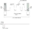
图7示出了根据本发明的实施例的用标准十进制数字字编码的传统的十进制AFLC载波或“纹波”信号的数字编码的细节以及引入AFLC阻抗的时序细节。可以看出,实现为电阻(R)的AFLC阻抗可以在检测到十进制数字字的起始脉冲的不到50毫秒内接入电路。因此,完整的AFLC信号可以旁路PFC电容器子系统,近92%的600毫秒宽的AFLC信号起始脉冲保持完好,以保证正常的AFLC继电器的可靠运行。Figure 7 shows details of the digital encoding of a conventional decimal AFLC carrier or "ripple" signal encoded with standard decimal digital words and the timing details of the introduction of the AFLC impedance, according to an embodiment of the invention. It can be seen that the AFLC impedance implemented as a resistor (R) can be switched into the circuit in less than 50 milliseconds of detection of the start pulse of the decimal digital word. Therefore, the intact AFLC signal can bypass the PFC capacitor subsystem, and nearly 92% of the 600 ms wide AFLC signal initiation pulse remains intact to guarantee the reliable operation of the normal AFLC relay.
本发明的另一个优点在于,在PF或无功功率KVAR校正中有效地使用了无源线路PFC电容器,因为无源PFC电容器消耗非常少的有功功率KW;当PFC电容器接合以在感性负载上增加超前的无功功率KVAR时,消耗的有功功率KW很少。校正PF或无功功率KVAR的另一种方法是采用有源的方式,这在业界已经很成熟,通常称为利用有源滤波器(APF)。美国专利No.5,321,598中公开了一种这样的APF。图8A中也示出了典型的APF拓扑结构。Another advantage of the present invention is that passive line PFC capacitors are effectively used in PF or reactive power KVAR correction because passive PFC capacitors consume very little active power KW; when PFC capacitors are engaged to increase on inductive load When the reactive power KVAR is advanced, the active power KW consumed is very small. Another way to correct PF or reactive power KVAR is to use an active approach, which is well established in the industry and is often referred to as utilizing an active filter (APF). One such APF is disclosed in US Patent No. 5,321,598. A typical APF topology is also shown in Figure 8A.
一般而言,PF或无功功率KVAR校正中的有源方式使用有源功率半导体开关器件而非无源电容器。另外,采用由各种方法的算法编程的高速微处理器或数字信号处理器,来计算需要注入电网的电流。为了恢复交流电流,使之与电压基波同相,将输电干线基频(例如50或60Hz)中的电流有源地注入电网线路中,以使电流波形与电压波形对齐,从而校正基频PF或最小化基波无功功率KVAR。通过再次有源地注入与电压或者电流谐波(其为输电干线基频的倍数)相反或相抵消的电流,也可以去除或最小化作为输电干线电源基频的倍数的谐波。In general, the active approach in PF or reactive power KVAR correction uses active power semiconductor switching devices instead of passive capacitors. In addition, high-speed microprocessors or digital signal processors programmed with algorithms of various methods are used to calculate the current that needs to be injected into the grid. To restore the AC current to be in phase with the voltage fundamental, a current at the transmission mains fundamental frequency (e.g. 50 or 60 Hz) is actively injected into the grid lines to align the current waveform with the voltage waveform, thereby correcting the fundamental frequency PF or Minimize fundamental reactive power KVAR. Harmonics that are multiples of the mains fundamental frequency can also be removed or minimized by again actively injecting currents that oppose or cancel voltage or current harmonics that are multiples of the mains fundamental frequency.
基于APF使用的有源方式的主要缺点是,在将相反电流注入电网线路以校正基频PF和一系列谐波中,能量损失非常明显,这很大程度上是由于功率半导体开关器件的操作、双倍功率转换拓扑结构、以及消耗大量功率的控制和功率电子器件。通常,APF的整体损耗可以是3-5%或更多,这取决于APF的设计以及电网中的负载。这些损失以热形式耗散。The main disadvantage of the active approach based on the use of APF is that in injecting the opposite current into the grid line to correct the fundamental frequency PF and a series of harmonics, the energy loss is very significant, largely due to the operation of the power semiconductor switching devices, Double power conversion topologies, and control and power electronics that consume large amounts of power. Typically, the overall loss of an APF can be 3-5% or more, depending on the design of the APF and the load in the grid. These losses are dissipated as heat.
另一方面,根据本发明的一个实施方式,通过使用低损耗、低热耗散和高效的无源线路PFC电容器来校正基频PF或KVAR,以及使用具有专门设计或配置的微控制器、微处理器、数字信号处理器和/或能够处理AC电流和电压信号并产生用于生成相反电流的定时电子驱动信号的其他数字或模拟装置的较低功率APF,整个电能质量功能的效率得以提升。这种较低功率的APF仅用于通过有源功率半导体装置来针对和消除或最小化作为输电干线基频的倍数的较高频谐波。On the other hand, according to one embodiment of the present invention, the fundamental frequency PF or KVAR is corrected by using low loss, low heat dissipation and high efficiency passive line PFC capacitors, and using a specially designed or configured microcontroller, microprocessor The efficiency of the overall power quality function is improved by using lower power APFs with converters, digital signal processors, and/or other digital or analog devices capable of processing AC current and voltage signals and generating timed electronic drive signals for generating opposing currents. This lower power APF is only used to target and cancel or minimize higher frequency harmonics which are multiples of the mains fundamental frequency by active power semiconductor devices.
图8A示出了用于具有产生纯正弦输入电流的AC电源(或输入)的电网的典型APF或谐波校正器。APF或谐波校正器包括电网线路上的电流感测(例如电流互感器),用于感测输入电流并在负载上产生必要的电流成分数据的。所感测的输入电流随后由涉及纯正弦信号的控制回路处理,从而确定并导致由功率因数和谐波补偿器引起和吸收的瞬时电流量的增加或减少。Figure 8A shows a typical APF or harmonic corrector for a grid with an AC source (or input) producing a pure sinusoidal input current. An APF or Harmonic Corrector includes current sensing (eg current transformers) on the grid line to sense the incoming current and generate the necessary current component data at the load. The sensed input current is then processed by a control loop involving a purely sinusoidal signal to determine and cause an increase or decrease in the amount of instantaneous current induced and absorbed by the power factor and harmonic compensator.
图8B示出了本发明的一个实施方式,其包括较低功率APF以及一个或多个高效无源PFC电容器,较低功率APF仅用于只消除或最小化幅值比基频(例如50Hz或60Hz)分量小的谐波含量,高效无源PFC电容器仅用于校正基频(例如50或60Hz)KVAR或PF。对于输电干线基频为50Hz的交流配电网,要消除或最小化的较高频谐波含量可以是i*50Hz,其中i={2,3,…,n};对于输电干线基频为60Hz的交流配电网,要消除或最小化的较高频谐波含量可以是i*60Hz,其中i={2,3,…,n}。Fig. 8B shows an embodiment of the present invention which includes a lower power APF and one or more high efficiency passive PFC capacitors, the lower power APF is only used to eliminate or minimize only the magnitude ratio 60Hz) components with small harmonic content, high-efficiency passive PFC capacitors are only used to correct the fundamental frequency (
本领域普通技术人员将认识到,本领域众所周知的任何APF拓扑结构都可以适用于仅针对高阶谐波而不偏离本发明的精神和范围,后者包括使用仅针对并消除或最小化幅值比基频分量小的谐波含量的较低功率的APF,以及使用一个或多个仅用于校正基频KVAR或PF的高效无源PFC电容器。Those of ordinary skill in the art will recognize that any APF topology known in the art may be adapted to target only higher order harmonics without departing from the spirit and scope of the invention, which includes using only A lower power APF with less harmonic content than the fundamental frequency component, and the use of one or more high-efficiency passive PFC capacitors that only correct the fundamental frequency KVAR or PF.
在电网使用电网音频信令或AFLC的情况下,根据本发明实施方式的APF配置为识别已选择的特定音频或AFLC频率。根据一个优选实施方式,APF提供具有可选菜单和/或电子或机电频率拨号器或用于手动编程的滑块的用户界面,该可选菜单示出了一些音频或AFLC频率,其可以预先定义在保存于非瞬态存储器的查找表中。APF随后被编程以允许在已选择的特定音频或AFLC频率处的音频或AFLC电压信号完全绕过APF,而不作为不希望的谐波被以任何方式消除或最小化。Where the grid uses grid audio signalling, or AFLC, the APF according to an embodiment of the invention is configured to recognize that a specific audio or AFLC frequency has been selected. According to a preferred embodiment, the APF provides a user interface with a selectable menu showing a number of audio or AFLC frequencies, which can be pre-defined, and/or electronic or electromechanical frequency dialers or sliders for manual programming In a look-up table held in non-transitory memory. The APF is then programmed to allow audio or AFLC voltage signals at specific audio or AFLC frequencies that have been selected to bypass the APF completely without being canceled or minimized in any way as unwanted harmonics.
本文公开的实施方式可以使用通用或专用计算设备、计算机处理器、微控制器或电子电路来实现,包括但不限于数字信号处理器(DSP)、专用集成电路(ASIC)、现场可编程门阵列(FPGA)以及根据本申请的教导而配置或编程的其他可编程逻辑器件。基于本申请的教导,软件或电子领域的普通技术人员可以容易地实现在通用或专用计算设备、计算机处理器或可编程逻辑设备中运行的计算机指令或软件代码。Embodiments disclosed herein can be implemented using general or special purpose computing devices, computer processors, microcontrollers, or electronic circuits, including but not limited to digital signal processors (DSPs), application specific integrated circuits (ASICs), field programmable gate arrays (FPGA) and other programmable logic devices configured or programmed according to the teachings of this application. Based on the teachings of the present application, computer instructions or software codes running in general or special purpose computing devices, computer processors or programmable logic devices can be readily implemented by one of ordinary skill in the field of software or electronics.
本发明的上述描述是仅用于说明和描述的目的,并不意在穷举或将本发明限制为所公开的精确形式。许多修改和变化对于本领域技术人员而言,将是显而易见的。The foregoing description of the present invention has been presented for purposes of illustration and description only, and is not intended to be exhaustive or to limit the invention to the precise forms disclosed. Many modifications and changes will be apparent to those skilled in the art.
实施方式的选择和描述是为了最好地解释本发明的原理及其实际应用,从而使本领域的其他技术人员能够理解本发明的各种实施例,以及适于预期的特定用途的各种修改。意图在于,本发明的范围由所附权利要求及其等效项限定。The embodiment was chosen and described in order to best explain the principles of the invention and its practical application, thereby enabling others skilled in the art to understand the invention for various embodiments, with various modifications as are suited to the particular use contemplated . It is intended that the scope of the invention be defined by the claims appended hereto and their equivalents.
Claims (13)
Applications Claiming Priority (2)
| Application Number | Priority Date | Filing Date | Title |
|---|---|---|---|
| US15/831,383US10027120B1 (en) | 2017-09-01 | 2017-12-04 | System and method for high efficiency power quality correction |
| US15/831383 | 2017-12-04 |
Publications (2)
| Publication Number | Publication Date |
|---|---|
| CN109873432A CN109873432A (en) | 2019-06-11 |
| CN109873432Btrue CN109873432B (en) | 2023-04-28 |
Family
ID=64721118
Family Applications (3)
| Application Number | Title | Priority Date | Filing Date |
|---|---|---|---|
| CN201820307036.8UActiveCN208316303U (en) | 2017-12-04 | 2018-03-06 | System for power factor and harmonic correction in grids |
| CN201810182873.7AActiveCN109873432B (en) | 2017-12-04 | 2018-03-06 | System for power factor and harmonic correction in an electrical grid |
| CN201880078152.XAActiveCN111466062B (en) | 2017-12-04 | 2018-11-20 | System and method for power factor PF and harmonic correction without overcompensation in a power grid |
Family Applications Before (1)
| Application Number | Title | Priority Date | Filing Date |
|---|---|---|---|
| CN201820307036.8UActiveCN208316303U (en) | 2017-12-04 | 2018-03-06 | System for power factor and harmonic correction in grids |
Family Applications After (1)
| Application Number | Title | Priority Date | Filing Date |
|---|---|---|---|
| CN201880078152.XAActiveCN111466062B (en) | 2017-12-04 | 2018-11-20 | System and method for power factor PF and harmonic correction without overcompensation in a power grid |
Country Status (5)
| Country | Link |
|---|---|
| EP (1) | EP3721522B1 (en) |
| CN (3) | CN208316303U (en) |
| AU (1) | AU2018379834B2 (en) |
| ES (1) | ES2982893T3 (en) |
| WO (1) | WO2019111080A1 (en) |
Families Citing this family (4)
| Publication number | Priority date | Publication date | Assignee | Title |
|---|---|---|---|---|
| CN208316303U (en)* | 2017-12-04 | 2019-01-01 | 逸节电子有限公司 | System for power factor and harmonic correction in grids |
| CN113904611B (en)* | 2021-10-15 | 2025-05-13 | 珠海格力节能环保制冷技术研究中心有限公司 | Voltage drive circuits, systems and home appliances |
| CN114006528B (en)* | 2022-01-04 | 2022-04-26 | 浙江大学杭州国际科创中心 | Current correction method suitable for broadband input PFC circuit |
| CN120236875A (en)* | 2025-05-28 | 2025-07-01 | 四川省渝源电器有限公司 | A new type of high-power inductor that can adapt to different working conditions |
Citations (1)
| Publication number | Priority date | Publication date | Assignee | Title |
|---|---|---|---|---|
| CN208316303U (en)* | 2017-12-04 | 2019-01-01 | 逸节电子有限公司 | System for power factor and harmonic correction in grids |
Family Cites Families (15)
| Publication number | Priority date | Publication date | Assignee | Title |
|---|---|---|---|---|
| CA2050068A1 (en)* | 1990-09-27 | 1992-03-28 | Richard Wayne Glaser | Power factor improving arrangement |
| US5321598A (en) | 1992-09-18 | 1994-06-14 | Westinghouse Electric Corp. | Three-phase active filter utilizing rotating axis transformation |
| US5387821A (en)* | 1992-11-12 | 1995-02-07 | Allegro Microsystems, Inc. | Power distribution circuit with power factor correction and independent harmonic current filter |
| US7804280B2 (en)* | 2006-11-02 | 2010-09-28 | Current Technologies, Llc | Method and system for providing power factor correction in a power distribution system |
| CN201260080Y (en)* | 2008-08-29 | 2009-06-17 | 东莞市友美电源设备有限公司 | Device for reactive compensation and harmonic suppression of intelligent power system |
| JP2011055477A (en)* | 2009-08-07 | 2011-03-17 | Rohm Co Ltd | Oscillator circuit with sweeping function and motor driving device using the same |
| WO2011091444A1 (en)* | 2010-01-25 | 2011-07-28 | Geneva Cleantech Inc. | Automatic detection of appliances |
| CN201893558U (en)* | 2010-12-07 | 2011-07-06 | 吉林省电力有限公司四平供电公司 | Active power filter and dynamic reactive power comprehensive compensation control device |
| CN102170135A (en)* | 2011-04-16 | 2011-08-31 | 湖南大学 | 35KV large capacity reactive compensation and harmonic suppression integrated system and control method thereof |
| CN102437728A (en)* | 2012-01-11 | 2012-05-02 | 西南交通大学 | Power factor correcting and converting method and device for eliminating power frequency ripple waves by peak load shifting |
| CN102664517B (en)* | 2012-05-08 | 2014-09-17 | 英飞特电子(杭州)股份有限公司 | Power factor correction circuit |
| CN105409084B (en)* | 2013-03-30 | 2018-12-04 | 逸节电子有限公司 | Algorithm for passive power factor compensation method with differential compensation variation and reduced line transient noise |
| US9882507B2 (en)* | 2013-04-16 | 2018-01-30 | Solarcity Corporation | Power factor adjustment in multi-phase power system |
| US11258371B2 (en)* | 2016-02-16 | 2022-02-22 | Psemi Corporation | Switched capacitors for AC-DC applications |
| US10027120B1 (en)* | 2017-09-01 | 2018-07-17 | Edge Electrons Limited | System and method for high efficiency power quality correction |
- 2018
- 2018-03-06CNCN201820307036.8Upatent/CN208316303U/enactiveActive
- 2018-03-06CNCN201810182873.7Apatent/CN109873432B/enactiveActive
- 2018-11-20AUAU2018379834Apatent/AU2018379834B2/enactiveActive
- 2018-11-20WOPCT/IB2018/059115patent/WO2019111080A1/ennot_activeCeased
- 2018-11-20ESES18884934Tpatent/ES2982893T3/enactiveActive
- 2018-11-20EPEP18884934.3Apatent/EP3721522B1/enactiveActive
- 2018-11-20CNCN201880078152.XApatent/CN111466062B/enactiveActive
Patent Citations (1)
| Publication number | Priority date | Publication date | Assignee | Title |
|---|---|---|---|---|
| CN208316303U (en)* | 2017-12-04 | 2019-01-01 | 逸节电子有限公司 | System for power factor and harmonic correction in grids |
Also Published As
| Publication number | Publication date |
|---|---|
| CN111466062B (en) | 2023-07-28 |
| CN208316303U (en) | 2019-01-01 |
| EP3721522C0 (en) | 2024-05-08 |
| AU2018379834B2 (en) | 2021-11-11 |
| EP3721522A4 (en) | 2021-05-05 |
| AU2018379834A1 (en) | 2020-06-18 |
| CN109873432A (en) | 2019-06-11 |
| CN111466062A (en) | 2020-07-28 |
| EP3721522A1 (en) | 2020-10-14 |
| EP3721522B1 (en) | 2024-05-08 |
| ES2982893T3 (en) | 2024-10-18 |
| WO2019111080A1 (en) | 2019-06-13 |
Similar Documents
| Publication | Publication Date | Title |
|---|---|---|
| US10027120B1 (en) | System and method for high efficiency power quality correction | |
| CN109873432B (en) | System for power factor and harmonic correction in an electrical grid | |
| US10848053B2 (en) | Robust inverter topology | |
| US20230187926A1 (en) | Ground fault minimization | |
| KR102262515B1 (en) | Hybrid power quality compensation device | |
| EP2783446A1 (en) | Active filter for resonance reduction | |
| GB2494770A (en) | Reactive power compensation system having capacitors with parallel connected discharge resistors | |
| KR101617857B1 (en) | Power saving of device | |
| EP3266111B1 (en) | Method and apparatus to solve pfc capacitor reduction of line aflc ripple without passive filters | |
| JP6037382B2 (en) | Harmonic suppression device | |
| AU2021469672B2 (en) | Stabilizing electrical power in an electrical grid | |
| JP4741875B2 (en) | Operation method of power supply device and power supply device | |
| WO2010105658A1 (en) | Method for preventing overvoltages, reactive power compensator, control system and computer program products | |
| Lin et al. | Implementation of a shunt-series compensator for nonlinear and voltage sensitive load | |
| Koolaiyan et al. | A voltage sag compensation utilizing autotransformer switched by hysteresis voltage control | |
| JP2020048314A (en) | Reactive power compensator | |
| TWI891772B (en) | Actively-controlled power transformer and method for controlling | |
| Jacobina et al. | Three-phase series active power filter without dc voltage source | |
| Kiran et al. | Voltage Sag Mitigation Using Pulse Width Modulation Switched Autotransformer through Matlab Simulation | |
| Ohnishi et al. | AC line voltage harmonics compensator with excessive current control | |
| Liebenberg et al. | Power Factor Correction for Thyristor Equipment in Glass Industry | |
| CN114026775A (en) | Electric arc furnace power supply with resonant circuit | |
| JP2006081292A (en) | Voltage regulator | |
| Tarnini | Simplified series active power filters |
Legal Events
| Date | Code | Title | Description |
|---|---|---|---|
| PB01 | Publication | ||
| PB01 | Publication | ||
| SE01 | Entry into force of request for substantive examination | ||
| SE01 | Entry into force of request for substantive examination | ||
| GR01 | Patent grant | ||
| GR01 | Patent grant |