CN109869812B - Air conditioner - Google Patents
Air conditionerDownload PDFInfo
- Publication number
- CN109869812B CN109869812BCN201910284511.3ACN201910284511ACN109869812BCN 109869812 BCN109869812 BCN 109869812BCN 201910284511 ACN201910284511 ACN 201910284511ACN 109869812 BCN109869812 BCN 109869812B
- Authority
- CN
- China
- Prior art keywords
- air
- airflow
- air conditioner
- fan
- unit
- Prior art date
- Legal status (The legal status is an assumption and is not a legal conclusion. Google has not performed a legal analysis and makes no representation as to the accuracy of the status listed.)
- Active
Links
Images


Classifications
- F—MECHANICAL ENGINEERING; LIGHTING; HEATING; WEAPONS; BLASTING
- F24—HEATING; RANGES; VENTILATING
- F24F—AIR-CONDITIONING; AIR-HUMIDIFICATION; VENTILATION; USE OF AIR CURRENTS FOR SCREENING
- F24F11/00—Control or safety arrangements
- F24F11/30—Control or safety arrangements for purposes related to the operation of the system, e.g. for safety or monitoring
- F—MECHANICAL ENGINEERING; LIGHTING; HEATING; WEAPONS; BLASTING
- F24—HEATING; RANGES; VENTILATING
- F24F—AIR-CONDITIONING; AIR-HUMIDIFICATION; VENTILATION; USE OF AIR CURRENTS FOR SCREENING
- F24F1/00—Room units for air-conditioning, e.g. separate or self-contained units or units receiving primary air from a central station
- F24F1/0003—Room units for air-conditioning, e.g. separate or self-contained units or units receiving primary air from a central station characterised by a split arrangement, wherein parts of the air-conditioning system, e.g. evaporator and condenser, are in separately located units
- F—MECHANICAL ENGINEERING; LIGHTING; HEATING; WEAPONS; BLASTING
- F24—HEATING; RANGES; VENTILATING
- F24F—AIR-CONDITIONING; AIR-HUMIDIFICATION; VENTILATION; USE OF AIR CURRENTS FOR SCREENING
- F24F1/00—Room units for air-conditioning, e.g. separate or self-contained units or units receiving primary air from a central station
- F24F1/0007—Indoor units, e.g. fan coil units
- F24F1/0011—Indoor units, e.g. fan coil units characterised by air outlets
- F—MECHANICAL ENGINEERING; LIGHTING; HEATING; WEAPONS; BLASTING
- F24—HEATING; RANGES; VENTILATING
- F24F—AIR-CONDITIONING; AIR-HUMIDIFICATION; VENTILATION; USE OF AIR CURRENTS FOR SCREENING
- F24F1/00—Room units for air-conditioning, e.g. separate or self-contained units or units receiving primary air from a central station
- F24F1/0007—Indoor units, e.g. fan coil units
- F24F1/0018—Indoor units, e.g. fan coil units characterised by fans
- F24F1/0022—Centrifugal or radial fans
- F—MECHANICAL ENGINEERING; LIGHTING; HEATING; WEAPONS; BLASTING
- F24—HEATING; RANGES; VENTILATING
- F24F—AIR-CONDITIONING; AIR-HUMIDIFICATION; VENTILATION; USE OF AIR CURRENTS FOR SCREENING
- F24F1/00—Room units for air-conditioning, e.g. separate or self-contained units or units receiving primary air from a central station
- F24F1/0007—Indoor units, e.g. fan coil units
- F24F1/0018—Indoor units, e.g. fan coil units characterised by fans
- F24F1/0033—Indoor units, e.g. fan coil units characterised by fans having two or more fans
- F—MECHANICAL ENGINEERING; LIGHTING; HEATING; WEAPONS; BLASTING
- F24—HEATING; RANGES; VENTILATING
- F24F—AIR-CONDITIONING; AIR-HUMIDIFICATION; VENTILATION; USE OF AIR CURRENTS FOR SCREENING
- F24F1/00—Room units for air-conditioning, e.g. separate or self-contained units or units receiving primary air from a central station
- F24F1/0007—Indoor units, e.g. fan coil units
- F24F1/0043—Indoor units, e.g. fan coil units characterised by mounting arrangements
- F24F1/0047—Indoor units, e.g. fan coil units characterised by mounting arrangements mounted in the ceiling or at the ceiling
- F—MECHANICAL ENGINEERING; LIGHTING; HEATING; WEAPONS; BLASTING
- F24—HEATING; RANGES; VENTILATING
- F24F—AIR-CONDITIONING; AIR-HUMIDIFICATION; VENTILATION; USE OF AIR CURRENTS FOR SCREENING
- F24F1/00—Room units for air-conditioning, e.g. separate or self-contained units or units receiving primary air from a central station
- F24F1/0007—Indoor units, e.g. fan coil units
- F24F1/0043—Indoor units, e.g. fan coil units characterised by mounting arrangements
- F24F1/0057—Indoor units, e.g. fan coil units characterised by mounting arrangements mounted in or on a wall
- F—MECHANICAL ENGINEERING; LIGHTING; HEATING; WEAPONS; BLASTING
- F24—HEATING; RANGES; VENTILATING
- F24F—AIR-CONDITIONING; AIR-HUMIDIFICATION; VENTILATION; USE OF AIR CURRENTS FOR SCREENING
- F24F1/00—Room units for air-conditioning, e.g. separate or self-contained units or units receiving primary air from a central station
- F24F1/0007—Indoor units, e.g. fan coil units
- F24F1/0071—Indoor units, e.g. fan coil units with means for purifying supplied air
- F24F1/0073—Indoor units, e.g. fan coil units with means for purifying supplied air characterised by the mounting or arrangement of filters
- F—MECHANICAL ENGINEERING; LIGHTING; HEATING; WEAPONS; BLASTING
- F24—HEATING; RANGES; VENTILATING
- F24F—AIR-CONDITIONING; AIR-HUMIDIFICATION; VENTILATION; USE OF AIR CURRENTS FOR SCREENING
- F24F11/00—Control or safety arrangements
- F—MECHANICAL ENGINEERING; LIGHTING; HEATING; WEAPONS; BLASTING
- F24—HEATING; RANGES; VENTILATING
- F24F—AIR-CONDITIONING; AIR-HUMIDIFICATION; VENTILATION; USE OF AIR CURRENTS FOR SCREENING
- F24F11/00—Control or safety arrangements
- F24F11/30—Control or safety arrangements for purposes related to the operation of the system, e.g. for safety or monitoring
- F24F11/41—Defrosting; Preventing freezing
- F24F11/42—Defrosting; Preventing freezing of outdoor units
- F—MECHANICAL ENGINEERING; LIGHTING; HEATING; WEAPONS; BLASTING
- F24—HEATING; RANGES; VENTILATING
- F24F—AIR-CONDITIONING; AIR-HUMIDIFICATION; VENTILATION; USE OF AIR CURRENTS FOR SCREENING
- F24F11/00—Control or safety arrangements
- F24F11/50—Control or safety arrangements characterised by user interfaces or communication
- F24F11/52—Indication arrangements, e.g. displays
- F—MECHANICAL ENGINEERING; LIGHTING; HEATING; WEAPONS; BLASTING
- F24—HEATING; RANGES; VENTILATING
- F24F—AIR-CONDITIONING; AIR-HUMIDIFICATION; VENTILATION; USE OF AIR CURRENTS FOR SCREENING
- F24F11/00—Control or safety arrangements
- F24F11/62—Control or safety arrangements characterised by the type of control or by internal processing, e.g. using fuzzy logic, adaptive control or estimation of values
- F24F11/63—Electronic processing
- F24F11/65—Electronic processing for selecting an operating mode
- F—MECHANICAL ENGINEERING; LIGHTING; HEATING; WEAPONS; BLASTING
- F24—HEATING; RANGES; VENTILATING
- F24F—AIR-CONDITIONING; AIR-HUMIDIFICATION; VENTILATION; USE OF AIR CURRENTS FOR SCREENING
- F24F11/00—Control or safety arrangements
- F24F11/70—Control systems characterised by their outputs; Constructional details thereof
- F24F11/72—Control systems characterised by their outputs; Constructional details thereof for controlling the supply of treated air, e.g. its pressure
- F24F11/74—Control systems characterised by their outputs; Constructional details thereof for controlling the supply of treated air, e.g. its pressure for controlling air flow rate or air velocity
- F24F11/77—Control systems characterised by their outputs; Constructional details thereof for controlling the supply of treated air, e.g. its pressure for controlling air flow rate or air velocity by controlling the speed of ventilators
- F—MECHANICAL ENGINEERING; LIGHTING; HEATING; WEAPONS; BLASTING
- F24—HEATING; RANGES; VENTILATING
- F24F—AIR-CONDITIONING; AIR-HUMIDIFICATION; VENTILATION; USE OF AIR CURRENTS FOR SCREENING
- F24F11/00—Control or safety arrangements
- F24F11/70—Control systems characterised by their outputs; Constructional details thereof
- F24F11/72—Control systems characterised by their outputs; Constructional details thereof for controlling the supply of treated air, e.g. its pressure
- F24F11/79—Control systems characterised by their outputs; Constructional details thereof for controlling the supply of treated air, e.g. its pressure for controlling the direction of the supplied air
- F—MECHANICAL ENGINEERING; LIGHTING; HEATING; WEAPONS; BLASTING
- F24—HEATING; RANGES; VENTILATING
- F24F—AIR-CONDITIONING; AIR-HUMIDIFICATION; VENTILATION; USE OF AIR CURRENTS FOR SCREENING
- F24F11/00—Control or safety arrangements
- F24F11/89—Arrangement or mounting of control or safety devices
- F—MECHANICAL ENGINEERING; LIGHTING; HEATING; WEAPONS; BLASTING
- F24—HEATING; RANGES; VENTILATING
- F24F—AIR-CONDITIONING; AIR-HUMIDIFICATION; VENTILATION; USE OF AIR CURRENTS FOR SCREENING
- F24F13/00—Details common to, or for air-conditioning, air-humidification, ventilation or use of air currents for screening
- F24F13/08—Air-flow control members, e.g. louvres, grilles, flaps or guide plates
- F24F13/082—Grilles, registers or guards
- F—MECHANICAL ENGINEERING; LIGHTING; HEATING; WEAPONS; BLASTING
- F24—HEATING; RANGES; VENTILATING
- F24F—AIR-CONDITIONING; AIR-HUMIDIFICATION; VENTILATION; USE OF AIR CURRENTS FOR SCREENING
- F24F13/00—Details common to, or for air-conditioning, air-humidification, ventilation or use of air currents for screening
- F24F13/20—Casings or covers
- F—MECHANICAL ENGINEERING; LIGHTING; HEATING; WEAPONS; BLASTING
- F24—HEATING; RANGES; VENTILATING
- F24F—AIR-CONDITIONING; AIR-HUMIDIFICATION; VENTILATION; USE OF AIR CURRENTS FOR SCREENING
- F24F13/00—Details common to, or for air-conditioning, air-humidification, ventilation or use of air currents for screening
- F24F13/24—Means for preventing or suppressing noise
- F—MECHANICAL ENGINEERING; LIGHTING; HEATING; WEAPONS; BLASTING
- F24—HEATING; RANGES; VENTILATING
- F24F—AIR-CONDITIONING; AIR-HUMIDIFICATION; VENTILATION; USE OF AIR CURRENTS FOR SCREENING
- F24F13/00—Details common to, or for air-conditioning, air-humidification, ventilation or use of air currents for screening
- F24F13/28—Arrangement or mounting of filters
- F—MECHANICAL ENGINEERING; LIGHTING; HEATING; WEAPONS; BLASTING
- F24—HEATING; RANGES; VENTILATING
- F24F—AIR-CONDITIONING; AIR-HUMIDIFICATION; VENTILATION; USE OF AIR CURRENTS FOR SCREENING
- F24F11/00—Control or safety arrangements
- F24F11/30—Control or safety arrangements for purposes related to the operation of the system, e.g. for safety or monitoring
- F24F11/41—Defrosting; Preventing freezing
- F—MECHANICAL ENGINEERING; LIGHTING; HEATING; WEAPONS; BLASTING
- F24—HEATING; RANGES; VENTILATING
- F24F—AIR-CONDITIONING; AIR-HUMIDIFICATION; VENTILATION; USE OF AIR CURRENTS FOR SCREENING
- F24F13/00—Details common to, or for air-conditioning, air-humidification, ventilation or use of air currents for screening
- F24F13/02—Ducting arrangements
- F24F13/06—Outlets for directing or distributing air into rooms or spaces, e.g. ceiling air diffuser
- F24F2013/0616—Outlets that have intake openings
- F—MECHANICAL ENGINEERING; LIGHTING; HEATING; WEAPONS; BLASTING
- F24—HEATING; RANGES; VENTILATING
- F24F—AIR-CONDITIONING; AIR-HUMIDIFICATION; VENTILATION; USE OF AIR CURRENTS FOR SCREENING
- F24F13/00—Details common to, or for air-conditioning, air-humidification, ventilation or use of air currents for screening
- F24F13/20—Casings or covers
- F24F2013/205—Mounting a ventilator fan therein
- F—MECHANICAL ENGINEERING; LIGHTING; HEATING; WEAPONS; BLASTING
- F24—HEATING; RANGES; VENTILATING
- F24F—AIR-CONDITIONING; AIR-HUMIDIFICATION; VENTILATION; USE OF AIR CURRENTS FOR SCREENING
- F24F2110/00—Control inputs relating to air properties
- F—MECHANICAL ENGINEERING; LIGHTING; HEATING; WEAPONS; BLASTING
- F24—HEATING; RANGES; VENTILATING
- F24F—AIR-CONDITIONING; AIR-HUMIDIFICATION; VENTILATION; USE OF AIR CURRENTS FOR SCREENING
- F24F2110/00—Control inputs relating to air properties
- F24F2110/10—Temperature
- F—MECHANICAL ENGINEERING; LIGHTING; HEATING; WEAPONS; BLASTING
- F24—HEATING; RANGES; VENTILATING
- F24F—AIR-CONDITIONING; AIR-HUMIDIFICATION; VENTILATION; USE OF AIR CURRENTS FOR SCREENING
- F24F2120/00—Control inputs relating to users or occupants
- F24F2120/10—Occupancy
- F24F2120/12—Position of occupants
- F—MECHANICAL ENGINEERING; LIGHTING; HEATING; WEAPONS; BLASTING
- F24—HEATING; RANGES; VENTILATING
- F24F—AIR-CONDITIONING; AIR-HUMIDIFICATION; VENTILATION; USE OF AIR CURRENTS FOR SCREENING
- F24F2221/00—Details or features not otherwise provided for
- F24F2221/28—Details or features not otherwise provided for using the Coanda effect
- Y—GENERAL TAGGING OF NEW TECHNOLOGICAL DEVELOPMENTS; GENERAL TAGGING OF CROSS-SECTIONAL TECHNOLOGIES SPANNING OVER SEVERAL SECTIONS OF THE IPC; TECHNICAL SUBJECTS COVERED BY FORMER USPC CROSS-REFERENCE ART COLLECTIONS [XRACs] AND DIGESTS
- Y02—TECHNOLOGIES OR APPLICATIONS FOR MITIGATION OR ADAPTATION AGAINST CLIMATE CHANGE
- Y02B—CLIMATE CHANGE MITIGATION TECHNOLOGIES RELATED TO BUILDINGS, e.g. HOUSING, HOUSE APPLIANCES OR RELATED END-USER APPLICATIONS
- Y02B30/00—Energy efficient heating, ventilation or air conditioning [HVAC]
- Y02B30/70—Efficient control or regulation technologies, e.g. for control of refrigerant flow, motor or heating
Landscapes
- Engineering & Computer Science (AREA)
- Combustion & Propulsion (AREA)
- Mechanical Engineering (AREA)
- General Engineering & Computer Science (AREA)
- Chemical & Material Sciences (AREA)
- Physics & Mathematics (AREA)
- Signal Processing (AREA)
- Human Computer Interaction (AREA)
- Fluid Mechanics (AREA)
- Mathematical Physics (AREA)
- Fuzzy Systems (AREA)
- Air Conditioning Control Device (AREA)
- Thermal Sciences (AREA)
- Air-Conditioning Room Units, And Self-Contained Units In General (AREA)
Abstract
Translated fromChinese
Description
Translated fromChinese本申请是申请日为2016年05月19日、申请号为201610334967.2的发明专利申请“空调及其控制方法”的分案申请。This application is a divisional application of the invention patent application "Air conditioner and its control method" with an application date of May 19, 2016 and an application number of 201610334967.2.
技术领域technical field
以下描述涉及空调及其控制方法,用于控制每个操作模式的排放气流。The following description relates to an air conditioner and a control method thereof for controlling the exhaust airflow for each operating mode.
背景技术Background technique
通常,空调是使用在使制冷剂蒸发和冷凝的过程中产生的热的传递来冷却、加热或净化被吸入的空气并排放空气从而调节室内空间的空气的设备。In general, an air conditioner is a device that cools, heats, or purifies drawn air and discharges air to condition air in an indoor space using transfer of heat generated in the process of evaporating and condensing refrigerant.
空调在夏天执行将室内的热向外部排放的冷却操作且在冬天执行使制冷剂按照与冷却循环的方式相反的方式循环以向室内供热的热泵的加热操作。The air conditioner performs a cooling operation of discharging indoor heat to the outside in summer and a heating operation of a heat pump that circulates refrigerant in a manner opposite to that of the cooling cycle to supply heat to the room in winter.
当执行冷却操作或加热操作时,空调使设置在室内热交换器附近的风扇旋转以吸入室内空气,在室内热交换器中与吸入的空气进行热交换,且在操作在排放部处设置的扇叶以调整被排放气流的方向的状态下将热交换后的空气排放到室内空间,从而调节室内空间的空气。When performing a cooling operation or a heating operation, the air conditioner rotates a fan provided near the indoor heat exchanger to suck indoor air, performs heat exchange with the sucked air in the indoor heat exchanger, and operates the fan provided at the discharge portion The blade discharges the heat-exchanged air to the indoor space while adjusting the direction of the air flow to be discharged, thereby adjusting the air in the indoor space.
发明内容SUMMARY OF THE INVENTION
将在随后的描述中部分地阐明其他方面和/或优点,且其他方面和/或优点将部分地通过该描述显而易见,或可通过本公开的实践而得知。Other aspects and/or advantages will be set forth in part in the description that follows, and in part will be apparent from the description, or may be learned by practice of the present disclosure.
本公开的一方面在于提供一种空调及其控制方法,其中,基于气流速度信息和气流方向信息控制多个风扇中的每个风扇的每分钟转数(RPM)。An aspect of the present disclosure is to provide an air conditioner and a method for controlling the same, in which the revolutions per minute (RPM) of each of a plurality of fans is controlled based on airflow speed information and airflow direction information.
本公开的一方面在于提供一种空调及其控制方法,其中,基于正常模式、高速模式或除霜模式控制多个风扇中的每个风扇的RPM。An aspect of the present disclosure is to provide an air conditioner and a control method thereof, wherein the RPM of each of a plurality of fans is controlled based on a normal mode, a high-speed mode, or a defrost mode.
本公开的一方面在于提供一种空调及其控制方法,其用于基于在吸入侧是否检测到灰尘或者是否检测到人而控制风扇的RPM。An aspect of the present disclosure is to provide an air conditioner and a control method thereof for controlling an RPM of a fan based on whether dust is detected on a suction side or whether a person is detected.
本公开的一方面在于提供一种空调及其控制方法,其中,打开和关闭流动通道被控制用于重复被排放的空气的热交换或排放。An aspect of the present disclosure is to provide an air conditioner and a control method thereof, in which opening and closing of a flow passage is controlled for repeating heat exchange or discharge of discharged air.
本公开的一方面在于按照不同方式控制从空调的室内单元向空气被调节空间排放的气流。An aspect of the present disclosure is to control the airflow discharged from the indoor unit of the air conditioner to the air-conditioned space in different ways.
本公开的一方面在于控制从室内单元排放的气流循环,以使即使在没有使室内单元旋转的情况下也可实现使室内单元旋转的效果。An aspect of the present disclosure is to control the circulation of airflow discharged from the indoor unit so that the effect of rotating the indoor unit can be achieved even without rotating the indoor unit.
本公开的一方面在于提供一种能够将显示单元牢固地固定到壳体的空调。An aspect of the present disclosure is to provide an air conditioner capable of securely fixing a display unit to a case.
本公开的一方面在于提供一种能够使用最少可能数量的独立固定构件将显示单元牢固地固定到壳体的空调。An aspect of the present disclosure is to provide an air conditioner capable of securely fixing a display unit to a housing using the least possible number of independent fixing members.
本公开的一方面在于提供一种通过使显示单元从壳体容易拆卸而能够便于显示单元的维护和修理的空调。An aspect of the present disclosure is to provide an air conditioner capable of facilitating maintenance and repair of a display unit by easily detaching the display unit from a housing.
本公开的一方面在于提供一种能够在没有扇叶的情况下控制气流方向的空调。An aspect of the present disclosure is to provide an air conditioner capable of controlling an airflow direction without a fan blade.
本公开的一方面在于提供一种在没有扇叶的情况下能够可视地表示气流方向的空调的控制方法。An aspect of the present disclosure is to provide a control method of an air conditioner that can visually indicate an airflow direction without a fan blade.
本公开的一方面在于提供一种空调及其控制方法,其中,可根据用户的操作检查可视地表示的气流方向。An aspect of the present disclosure is to provide an air conditioner and a control method thereof, in which a visually represented airflow direction can be checked according to a user's operation.
本公开的一方面在于提供一种空调及其控制方法,其能够不仅可视地表示气流的方向,还能够表示气流的强度和操作状态等。An aspect of the present disclosure is to provide an air conditioner and a control method thereof, which can visually represent not only the direction of the airflow, but also the intensity, operation state, and the like of the airflow.
根据一方面,空调包括室外单元和室内单元,其中,室内单元包括:壳体,其具有吸入部和排放部;热交换器,其设置在壳体中且被构造成与周围的空气进行热交换;主风扇,其通过吸入部抽吸室内空间的空气且通过排放部排放在热交换器中热交换后的空气;辅助风扇,其抽吸通过排放部排放的空气中的一部分空气;流动通道部,其引导被辅助风扇抽吸的空气的流动;控制单元,其基于主风扇的RPM控制辅助风扇的每分钟转数(RPM),以使调整通过排放部排放的气流的方向。According to one aspect, an air conditioner includes an outdoor unit and an indoor unit, wherein the indoor unit includes: a casing having a suction portion and a discharge portion; and a heat exchanger disposed in the casing and configured to exchange heat with ambient air ; the main fan, which sucks the air in the indoor space through the suction part and discharges the air after heat exchange in the heat exchanger through the discharge part; the auxiliary fan, which suctions a part of the air in the air discharged through the discharge part; the flow channel part , which directs the flow of air drawn by the auxiliary fan; and a control unit, which controls the revolutions per minute (RPM) of the auxiliary fan based on the RPM of the main fan, so as to adjust the direction of the air flow discharged through the discharge part.
根据本方面,空调还可包括用以容纳辅助风扇的箱体,流动通道部可包括:入口部,空气通过辅助风扇经该入口部被引入;出口部,被引入的空气通过该出口部向外部排放;流动通道,其连接到箱体且被构造成将经入口部被引入的空气引导到出口部。According to this aspect, the air conditioner may further include a case for accommodating the auxiliary fan, and the flow passage portion may include an inlet portion through which air is introduced by the auxiliary fan, and an outlet portion through which the introduced air is directed to the outside. A discharge; a flow passage connected to the tank and configured to direct air introduced through the inlet portion to the outlet portion.
根据本方面,空调还可包括输入单元,以接收关于气流速度的信息和关于气流方向的信息中的至少一者,控制单元可基于关于气流速度的信息而控制主风扇的RPM以及基于主风扇的RPM和关于气流方向的信息而控制辅助风扇的RPM。According to this aspect, the air conditioner may further include an input unit to receive at least one of the information on the airflow speed and the information on the airflow direction, and the control unit may control the RPM of the main fan based on the information on the airflow speed and the RPM of the main fan based on the information on the airflow speed. RPM and information about the direction of airflow to control the RPM of the auxiliary fan.
根据本方面,当接收高速模式时,空调的控制单元可将主风扇的RPM控制为预设的RPM并将辅助风扇的RPM控制为循环地改变。According to this aspect, when the high-speed mode is received, the control unit of the air conditioner may control the RPM of the main fan to be a preset RPM and control the RPM of the auxiliary fan to change cyclically.
根据本方面,空调还可包括用以检测室内空间的温度的室内温度检测单元,控制单元可包括当室内空间的温度为目标温度时将辅助风扇的RPM控制为预设的RPM。According to this aspect, the air conditioner may further include an indoor temperature detection unit to detect the temperature of the indoor space, and the control unit may include controlling the RPM of the auxiliary fan to a preset RPM when the temperature of the indoor space is the target temperature.
根据本方面,空调还可包括用以检测人体的检测单元,当接收高速模式时,控制单元可将主风扇的RPM控制为预设的RPM、基于检测到的关于人体的信息而检查人体的位置以及基于检查到的位置和主风扇的RPM而控制辅助风扇的RPM。According to this aspect, the air conditioner may further include a detection unit for detecting a human body, and when the high-speed mode is received, the control unit may control the RPM of the main fan to a preset RPM, check the position of the human body based on the detected information on the human body And control the RPM of the auxiliary fan based on the checked position and the RPM of the main fan.
根据本方面,当操作模式为加热操作时,空调的控制单元可确定除霜操作的开始点、当达到除霜操作的开始点时将主风扇控制为停止以及将辅助风扇的RPM控制为预设的RPM。According to this aspect, when the operation mode is the heating operation, the control unit of the air conditioner may determine the start point of the defrosting operation, control the main fan to stop when the start point of the defrosting operation is reached, and control the RPM of the auxiliary fan to be preset RPM.
根据本方面,当操作模式为加热操作时,空调的控制单元可确定除霜操作的开始点、当达到除霜操作的开始点时将主风扇控制为停止以及基于在加热操作期间的主风扇的RPM而控制辅助风扇的RPM。According to the present aspect, when the operation mode is the heating operation, the control unit of the air conditioner may determine the start point of the defrosting operation, control the main fan to stop when the start point of the defrosting operation is reached, and control the main fan to stop based on the operation of the main fan during the heating operation RPM and control the RPM of the auxiliary fan.
根据本方面,空调还可包括设置在吸入部处的过滤部和检测在过滤部中的灰尘量的灰尘检测单元,控制单元可基于在过滤部中的灰尘量而将辅助风扇的RPM控制为被补偿。According to this aspect, the air conditioner may further include a filter portion provided at the suction portion and a dust detection unit that detects the amount of dust in the filter portion, and the control unit may control the RPM of the auxiliary fan to be controlled based on the amount of dust in the filter portion compensate.
根据本方面,空调还可包括用以将驱动力施加到主风扇的第一马达和用以检测第一马达的电流的电流检测单元,控制单元可基于检测到的电流而将辅助风扇的RPM控制为使其被补偿。According to this aspect, the air conditioner may further include a first motor to apply a driving force to the main fan and a current detection unit to detect a current of the first motor, and the control unit may control the RPM of the auxiliary fan based on the detected current to be compensated.
根据本方面,空调还可包括用以将驱动力施加到主风扇的第一马达,控制单元可在操作期间基于使第一马达按照最大RPM旋转的第一占空比和使第一马达按照最大RPM旋转的第二占空比而将辅助风扇的RPM控制为被补偿。According to the present aspect, the air conditioner may further include a first motor to apply a driving force to the main fan, and the control unit may rotate the first motor at a maximum RPM based on a first duty ratio and rotate the first motor at a maximum RPM during operation. The second duty cycle of RPM rotation controls the RPM of the auxiliary fan to be compensated.
根据本方面,空调可包括用以容纳辅助风扇的箱体,流动通道部可包括:入口部,空气通过辅助风扇经该入口部被引入;第一出口部,其设置在排放部侧且被构造成将引入的空气向外部排放;第二出口部,其设置在热交换器侧且被构造成将引入的空气向热交换器排放;流动通道,其连接到箱且被构造成将通过入口部被引入的空气引导到第一出口部或第二出口部;第一开闭构件,其设置在流动通道中以打开和关闭第一出口部;第二开闭构件,其设置在流动通道中以打开和关闭第二出口部。According to this aspect, the air conditioner may include a case to accommodate the auxiliary fan, and the flow passage portion may include: an inlet portion through which air is introduced by the auxiliary fan, and a first outlet portion provided on the discharge portion side and configured to discharge the introduced air to the outside; a second outlet portion provided on the heat exchanger side and configured to discharge the introduced air to the heat exchanger; a flow passage connected to the tank and configured to pass through the inlet portion The introduced air is guided to the first outlet portion or the second outlet portion; a first opening and closing member provided in the flow passage to open and close the first outlet portion; and a second opening and closing member provided in the flow passage to Open and close the second outlet.
根据本方面,空调的控制单元可当工作模式为正常模式时控制第一开闭构件打开且控制第二开闭构件关闭以及当工作模式为高速模式时控制第一开闭构件关闭且控制第二开闭构件打开。According to the present aspect, the control unit of the air conditioner may control the first opening and closing member to open and control the second opening and closing member to close when the operation mode is the normal mode and control the first opening and closing member to close and control the second opening and closing member when the operation mode is the high speed mode The opening and closing member is opened.
根据本方面,空调的控制单元可当工作模式为高速模式时将辅助风扇的RPM控制为补偿。According to the present aspect, the control unit of the air conditioner may control the RPM of the auxiliary fan to compensate when the operation mode is the high speed mode.
根据本公开的一方面,一种空调包括室外单元和室内单元,其中,室内单元包括:壳体,其具有吸入部和排放部;热交换器,其设置在壳体中且被构造成与周围的空气进行热交换;主风扇,其通过吸入部抽吸室内空间的空气且通过排放部将在热交换器中热交换后的空气排放;辅助风扇,其抽吸通过排放部排放的空气中的一部分空气;流动通道部,其具有与排放部相邻设置的入口部、与热交换器相邻设置的第一出口部以及与排放部相邻设置的第二出口部,该流动通道部被构造成将通过入口部被引入的空气引导到第一出口部或第二出口部;控制单元,其基于主风扇的RPM控制辅助风扇RPM以调整通过排放部排放的气流的方向且基于工作模式控制第一出口部和第二出口部打开和关闭。According to an aspect of the present disclosure, an air conditioner includes an outdoor unit and an indoor unit, wherein the indoor unit includes: a case having a suction part and a discharge part; and a heat exchanger provided in the case and configured to communicate with surroundings The main fan, which sucks the air in the indoor space through the suction part and discharges the air after heat exchange in the heat exchanger through the discharge part; the auxiliary fan, which suctions the air in the air discharged through the discharge part a portion of air; a flow channel portion having an inlet portion positioned adjacent to the discharge portion, a first outlet portion positioned adjacent to the heat exchanger, and a second outlet portion positioned adjacent to the discharge portion, the flow channel portion being configured In order to guide the air introduced through the inlet part to the first outlet part or the second outlet part; a control unit which controls the auxiliary fan RPM based on the RPM of the main fan to adjust the direction of the air flow discharged through the discharge part and controls the first outlet part based on the operating mode An outlet portion and a second outlet portion are opened and closed.
根据本方面,空调的流动通道部可包括:流动通道,其连接到入口部、第一出口部和第二出口部;第一开闭构件,其设置在流动通道中以打开和关闭第一出口部;以及第二开闭构件,其设置在流动通道中以打开和关闭第二出口部。According to the present aspect, the flow passage part of the air conditioner may include: a flow passage connected to the inlet part, the first outlet part, and the second outlet part; and a first opening and closing member provided in the flow passage to open and close the first outlet part; and a second opening and closing member provided in the flow channel to open and close the second outlet part.
根据本方面,空调的控制单元可当工作模式为正常模式时控制第一开闭构件打开且控制第二开闭构件关闭以及当工作模式为高速模式时控制第一开闭构件关闭且控制第二开闭构件打开。According to the present aspect, the control unit of the air conditioner may control the first opening and closing member to open and control the second opening and closing member to close when the operation mode is the normal mode and control the first opening and closing member to close and control the second opening and closing member when the operation mode is the high speed mode The opening and closing member is opened.
根据一方面,一种空调包括室外单元和室内单元,其中,室内单元包括:壳体,其具有吸入部和排放部;热交换器,其设置在壳体中且被构造成与周围的空气进行热交换;主风扇,其通过吸入部抽吸室内空间的空气且通过排放部将在热交换器中进行热交换后的空气排放;辅助风扇,其抽吸通过排放部排放的空气中的一部分空气;流动通道部,其引导通过辅助风扇被抽吸的空气;室内温度检测单元,其检测室内空间的温度;控制单元,其在工作模式为高速模式时将主风扇的RPM控制为预设的RPM且将辅助风扇的RPM控制为循环地改变并且当室内空间的温度为目标温度时将辅助风扇的RPM控制为维持在预设的RPM。According to one aspect, an air conditioner includes an outdoor unit and an indoor unit, wherein the indoor unit includes: a housing having a suction portion and a discharging portion; and a heat exchanger provided in the housing and configured to communicate with ambient air heat exchange; a main fan that sucks air in the indoor space through a suction part and discharges the air after heat exchange in the heat exchanger through a discharge part; an auxiliary fan that suctions a part of the air discharged through the discharge part a flow channel portion that guides the air sucked by the auxiliary fan; an indoor temperature detection unit that detects the temperature of the indoor space; a control unit that controls the RPM of the main fan to a preset RPM when the operating mode is the high-speed mode And the RPM of the auxiliary fan is controlled to change cyclically and is controlled to be maintained at a preset RPM when the temperature of the indoor space is the target temperature.
根据本方面,当将将辅助风扇的RPM控制为循环地改变时,空调的控制单元可将辅助风扇控制为循环地启动和关闭。According to the present aspect, when the RPM of the auxiliary fan is controlled to be changed cyclically, the control unit of the air conditioner may control the auxiliary fan to be turned on and off cyclically.
根据一方面,一种控制具有室外单元和室内单元的空调的方法包括:当输入操作命令时操作设置在室外单元中的压缩机、使设置在室内单元中的主风扇旋转以及基于主风扇的RPM而操作在室内单元中设置的辅助风扇,其中,辅助风扇的操作可包括吸入被排放空气中的一部分,以调整通过室内单元的排放部排放的空气的方向。According to an aspect, a method of controlling an air conditioner having an outdoor unit and an indoor unit includes operating a compressor provided in the outdoor unit, rotating a main fan provided in the indoor unit, and an RPM based on the main fan when an operation command is input While operating the auxiliary fan provided in the indoor unit, the operation of the auxiliary fan may include sucking a part of the discharged air to adjust the direction of the air discharged through the discharge portion of the indoor unit.
根据本方面,控制空调的方法还可包括:当输入关于气流速度的信息和关于气流方向的信息中的至少一者时基于关于气流速度的信息而控制主风扇的RPM并基于主风扇的RPM和关于气流方向的信息而控制辅助风扇的RPM。According to the present aspect, the method of controlling the air conditioner may further include: controlling the RPM of the main fan based on the information on the airflow speed and based on the RPM of the main fan and the Information on the direction of airflow controls the RPM of the auxiliary fan.
根据本方面,控制空调的方法还可包括当工作模式为高速模式时将主风扇的RPM控制为预设的RPM且将辅助风扇的RPM控制为循环地改变并且当室内空间的温度为目标温度时将辅助风扇的RPM控制为维持在预设的RPM。According to the present aspect, the method of controlling the air conditioner may further include controlling the RPM of the main fan to a preset RPM and the RPM of the auxiliary fan to cyclically change when the operation mode is the high speed mode and when the temperature of the indoor space is the target temperature The RPM of the auxiliary fan is controlled to be maintained at the preset RPM.
根据本方面,空调的控制方法还可包括当工作模式为高速模式时将主风扇的RPM控制为预设的RPM、检测在室内空间中的人体以及基于检查到的人体的位置以及主风扇的RPM而控制辅助风扇的RPM。According to this aspect, the control method of the air conditioner may further include controlling the RPM of the main fan to a preset RPM when the operation mode is the high speed mode, detecting a human body in the indoor space, and the RPM of the main fan based on the position of the detected human body and the main fan And control the RPM of the auxiliary fan.
根据本方面,空调的控制方法还可包括当操作模式为加热操作时确定除霜操作的开始点、在当前时间点为除霜操作的开始点时控制主风扇停止以及将辅助风扇的RPM控制为预设的RPM。确定除霜操作的开始点可包括基于设置在室外单元中的室外热交换器的温度和室外温度而确定除霜操作的开始点。According to this aspect, the control method of the air conditioner may further include determining a start point of the defrosting operation when the operation mode is the heating operation, controlling the main fan to stop when the current time point is the start point of the defrosting operation, and controlling the RPM of the auxiliary fan to be Default RPM. Determining the start point of the defrosting operation may include determining the start point of the defrosting operation based on the temperature of the outdoor heat exchanger provided in the outdoor unit and the outdoor temperature.
根据本方面,空调的控制方法还可包括在除霜操作期间确定除霜操作的结束点以及在当前时间点为除霜操作的结束点时控制主风扇和辅助风扇停止。确定除霜操作的结束点可包括基于设置在室外单元中的室外热交换器的温度和室外温度而确定除霜操作的结束点。确定除霜操作的结束点可包括基于除霜操作的持续时间而确定除霜操作的结束点。According to this aspect, the control method of the air conditioner may further include determining an end point of the defrosting operation during the defrosting operation and controlling the main fan and the auxiliary fan to stop when the current time point is the end point of the defrosting operation. Determining the end point of the defrosting operation may include determining the end point of the defrosting operation based on the temperature of the outdoor heat exchanger provided in the outdoor unit and the outdoor temperature. Determining the end point of the defrost operation may include determining the end point of the defrost operation based on a duration of the defrost operation.
根据本方面,空调的控制方法还可包括检测设置在室内单元的吸入部处的过滤部中的灰尘量以及基于过滤部中的灰尘量而将辅助风扇的RPM控制为被补偿。According to this aspect, the control method of the air conditioner may further include detecting an amount of dust in a filter portion provided at the suction portion of the indoor unit and controlling the RPM of the auxiliary fan to be compensated based on the amount of dust in the filter portion.
根据本方面,空调的控制方法还可包括检查将驱动力施加到主风扇的第一马达的输出以及基于检查的第一马达的输出而将辅助风扇的RPM控制为被补偿。According to the present aspect, the control method of the air conditioner may further include checking the output of the first motor applying the driving force to the main fan and controlling the RPM of the auxiliary fan to be compensated based on the checked output of the first motor.
根据本方面,空调的控制方法还可包括检查将驱动力施加到主风扇的第一马达的电流以及基于检查的第一马达的电流而将辅助风扇的RPM控制为被补偿。According to the present aspect, the control method of the air conditioner may further include checking the current of the first motor applying the driving force to the main fan and controlling the RPM of the auxiliary fan to be compensated based on the checked current of the first motor.
根据本方面,空调的控制方法可包括当工作模式为正常模式时将由辅助风扇抽吸的空气朝向室内单元的排放部引导以及当工作模式为高速模式时将由辅助风扇抽吸的空气朝向室内单元的热交换器引导。According to the present aspect, the control method of the air conditioner may include directing air drawn by the auxiliary fan toward the discharge portion of the indoor unit when the operation mode is the normal mode and directing the air drawn by the auxiliary fan toward the discharge portion of the indoor unit when the operation mode is the high-speed mode Heat exchanger guide.
根据本方面,空调的控制方法可包括当工作模式为高速模式时基于主风扇的转数而将辅助风扇的RPM控制为补偿。According to the present aspect, the control method of the air conditioner may include controlling the RPM of the auxiliary fan to compensate based on the rotation number of the main fan when the operation mode is the high speed mode.
根据一方面,一种空调包括:壳体,其具有吸入部和多个排放部;气流产生单元,其通过将通过吸入部被抽吸的空气通过多个排放部排放而产生被排放气流;多个气流切换单元,其设置成改变被排放气流的状态;控制单元,其将从多个排放部中的至少一个排放部产生的被排放气流的状态控制为与从剩余排放部产生的被排放气流的状态区分开,同时控制多个气流切换单元,以使排放部的产生区分的被排放气流的位置在多个排放部中循环。According to one aspect, an air conditioner includes: a casing having a suction part and a plurality of discharge parts; an air flow generating unit generating a discharged air flow by discharging air sucked through the suction part through the plurality of discharge parts; an air flow switching unit configured to change the state of the discharged air flow; a control unit for controlling the state of the discharged air flow generated from at least one of the plurality of discharge parts to be the same as the discharged air flow generated from the remaining discharge parts The state of the discharge part is divided, and the plurality of air flow switching units are controlled at the same time, so that the position of the discharge part that generates the divided discharged air flow is circulated in the plurality of discharge parts.
根据本方面,在空调中,多个气流切换单元可形成有多个风扇,其抽吸被排放气流的空气中的一些空气以改变被排放气流的方向。According to the present aspect, in the air conditioner, the plurality of air flow switching units may be formed with a plurality of fans that suck some of the air of the discharged air flow to change the direction of the discharged air flow.
根据本方面,在空调中,控制多个气流切换单元可以是将多个风扇中的至少一个风扇的启动/关闭状态控制为与剩余风扇中的每一者的启动/关闭状态区分开。According to the present aspect, in the air conditioner, controlling the plurality of airflow switching units may be to control the on/off state of at least one of the plurality of fans to be distinguished from the on/off state of each of the remaining fans.
根据本方面,在空调中,控制多个气流切换单元可以是将多个风扇中的至少一个风扇的RPM控制为与剩余风扇中的每一者的RPM区分开。According to the present aspect, in the air conditioner, controlling the plurality of airflow switching units may be to control the RPM of at least one of the plurality of fans to be differentiated from the RPM of each of the remaining fans.
根据本方面,在空调中,控制多个气流切换单元是将多个风扇中的至少一个风扇的启动/关闭状态和RPM控制为与剩余风扇的启动/关闭状态和RPM区分开。According to the present aspect, in the air conditioner, controlling the plurality of airflow switching units is to control the on/off state and RPM of at least one of the plurality of fans to be distinguished from the on/off states and RPMs of the remaining fans.
根据本方面,在空调中,多个气流切换单元可以是多个扇叶,其分别安装在多个排放部上,以使其角度在打开状态和关闭状态之间的预定范围内调整,从而根据调整后的角度切换被排放气流的方向。According to the present aspect, in the air conditioner, the plurality of air flow switching units may be a plurality of fan blades, which are respectively installed on the plurality of discharge portions so that the angles thereof are adjusted within a predetermined range between an open state and a closed state, thereby The adjusted angle switches the direction of the discharged airflow.
根据本方面,在空调中,控制多个气流切换单元可以是将多个扇叶中的至少一个扇叶的启动/关闭状态控制为与剩余扇叶中的每一者的启动/关闭状态区分开。According to the present aspect, in the air conditioner, controlling the plurality of airflow switching units may be to control the on/off state of at least one of the plurality of fan blades to be distinguished from the on/off state of each of the remaining fan blades .
根据本方面,在空调中,控制多个气流切换单元可以是将多个扇叶中的至少一个扇叶的固定/摆动状态控制为与剩余扇叶中的每一者的固定/摆动状态区分开。According to the present aspect, in the air conditioner, controlling the plurality of airflow switching units may be to control the fixed/swing state of at least one of the plurality of fan blades to be distinguished from the fixed/swing state of each of the remaining fan blades .
根据本方面,在空调中,控制多个气流切换单元可以是将多个扇叶中的至少一个扇叶的启动/关闭状态和固定/摆动状态控制为与剩余扇叶中的每一者的启动/关闭状态和固定/摆动状态区分开。According to the present aspect, in the air conditioner, controlling the plurality of airflow switching units may be controlling the on/off state and the fixed/swing state of at least one of the plurality of fan blades to be the same as the activation of each of the remaining fan blades The /closed state is distinguished from the fixed/swing state.
根据本方面,空调还可包括:热交换器,其设置在壳体中以与通过吸入部被抽吸空气交换热;气流产生单元,其被设置成通过多个排放部排放通过热交换器进行热交换后的空气。According to the present aspect, the air conditioner may further include: a heat exchanger provided in the casing to exchange heat with the air drawn through the suction part; and an airflow generating unit provided to discharge through the heat exchanger through the plurality of discharge parts Air after heat exchange.
根据一方面,一种空调的控制方法包括:使用气流产生单元,通过多个排放部排放经吸入部被抽吸的空气而产生被排放气流;使用多个气流切换单元改变被排放气流的状态;以及将从多个排放部中的至少一个排放部产生的被排放气流的状态控制为与从剩余排放部中的每一个排放部产生的被排放气流的状态区分,同时控制多个气流切换单元,以使排放部的产生区分的被排放气流的位置在多个排放部中循环。According to one aspect, a control method of an air conditioner includes: using an airflow generating unit to discharge air sucked through a suction part through a plurality of discharge parts to generate a discharged airflow; using a plurality of airflow switching units to change the state of the discharged airflow; and controlling the state of the discharged air flow generated from at least one of the plurality of discharge portions to be differentiated from the state of the discharged air flow generated from each of the remaining discharge portions, while controlling the plurality of air flow switching units, The discharge parts are circulated in a plurality of discharge parts so that the position of the discharged air flow differentiated by the discharge parts is generated.
根据本方面,在空调的控制方法中,多个气流切换单元可形成有多个风扇,其通过吸入被排放气流的空气中的一些空气而改变被排放气流的方向。According to the present aspect, in the control method of the air conditioner, the plurality of air flow switching units may be formed with a plurality of fans that change the direction of the discharged air flow by sucking some of the air of the discharged air flow.
根据本方面,在空调的控制方法中,控制多个气流切换单元可以是将多个风扇中的至少一个风扇的启动/关闭状态控制为与剩余风扇中的每一者的启动/关闭状态区分开。According to the present aspect, in the control method of the air conditioner, controlling the plurality of airflow switching units may be to control the on/off state of at least one of the plurality of fans to be distinguished from the on/off state of each of the remaining fans .
根据本方面,在空调的控制方法中,控制多个气流切换单元可以是将多个风扇中的至少一个风扇的RPM控制为与剩余风扇中的每一者的RPM区分开。According to the present aspect, in the control method of the air conditioner, controlling the plurality of airflow switching units may be to control the RPM of at least one of the plurality of fans to be differentiated from the RPM of each of the remaining fans.
根据本方面,在空调的控制方法中,控制多个气流切换单元可以是将多个风扇中的至少一个风扇的启动/关闭状态和RPM控制为与剩余风扇中的每一者的启动/关闭状态和RPM区分开。According to the present aspect, in the control method of the air conditioner, controlling the plurality of airflow switching units may be controlling the on/off state and RPM of at least one fan of the plurality of fans to the on/off state of each of the remaining fans Separate from RPM.
根据本方面,在空调的控制方法中,多个气流切换单元可以是多个扇叶,其分别安装在多个排放部上以使其角度在打开状态和关闭状态之间的预定范围内调整,从而根据调整后的角度切换被排放气流的方向。According to the present aspect, in the control method of the air conditioner, the plurality of airflow switching units may be a plurality of fan blades, which are respectively installed on the plurality of discharge portions so that their angles are adjusted within a predetermined range between an open state and a closed state, Thus, the direction of the discharged airflow is switched according to the adjusted angle.
根据本方面,在空调的控制方法中,控制多个气流切换单元可是将多个扇叶中的至少一个扇叶的启动/关闭状态控制为与剩余扇叶中的每一者的启动/关闭状态区分开。According to the present aspect, in the control method of the air conditioner, controlling the plurality of airflow switching units may control the on/off state of at least one of the plurality of fan blades to be the same as the on/off state of each of the remaining fan blades differentiate.
根据本方面,在空调的控制方法中,控制多个气流切换单元可以是将多个扇叶中的至少一个扇叶的固定/摆动状态控制为与剩余扇叶中的每一者的固定/摆动状态区分开。According to this aspect, in the control method of an air conditioner, controlling the plurality of airflow switching units may be to control the fixed/swing state of at least one of the plurality of blades to be fixed/swing with each of the remaining blades Status is differentiated.
根据本方面,在空调的控制方法中,控制多个气流切换单元可以是将多个扇叶中的至少一个扇叶的启动/关闭状态和固定/摆动状态控制为与剩余扇叶中的每一者的启动/关闭状态和固定/摆动状态区分开。According to this aspect, in the control method of an air conditioner, controlling the plurality of airflow switching units may be to control the on/off state and the fixed/swing state of at least one of the plurality of fan blades to be the same as each of the remaining fan blades The on/off state and the fixed/swing state of the user are distinguished.
根据本方面,空调的控制方法还可包括通过热交换器与通过吸入部被抽吸的空气进行热交换,气流产生单元可被设置成通过多个排放部排放通过热交换器进行热交换后的空气。According to the present aspect, the control method of the air conditioner may further include exchanging heat with the air sucked through the suction part through a heat exchanger, and the airflow generating unit may be configured to discharge the heat-exchanged air through the heat exchanger through the plurality of discharge parts. Air.
根据一方面,一种空调包括:壳体,其具有吸入部和多个排放部;主风扇,其通过将通过吸入部被抽吸的空气通过多个排放部排放而产生被排放气流;多个辅助风扇,其设置成利用吸入通过多个排放部排放的空气中的一些空气而改变通过多个排放部排放的被排放气流的方向;控制单元,其将从多个排放部中的至少一个排放部产生的被排放气流的方向控制为与从剩余排放部产生的被排放气流的方向区分开,同时控制多个辅助风扇,以使排放部的产生区分的被排放气流的位置在多个排放部中循环。According to one aspect, an air conditioner includes: a casing having a suction part and a plurality of discharge parts; a main fan that generates a discharged air flow by discharging air drawn through the suction part through the plurality of discharge parts; a plurality of discharge parts; an auxiliary fan arranged to change the direction of the discharged air flow discharged through the plurality of discharge parts by taking in some of the air discharged through the plurality of discharge parts; a control unit which will discharge from at least one of the plurality of discharge parts The direction of the discharged air flow generated by the discharge portion is controlled to be differentiated from the direction of the discharged air flow generated from the remaining discharge portion, and a plurality of auxiliary fans are controlled simultaneously, so that the position of the discharged air flow differentiated by the discharge portion is in the plurality of discharge portions. medium cycle.
根据一方面,一种空调包括:壳体,其具有吸入部和多个排放部;主风扇,其通过将通过吸入部被抽吸的空气通过多个排放部排放而产生被排放气流;多个扇叶,其设置成利用吸入通过多个排放部排放的空气中的一些空气而改变通过多个排放部排放的被排放气流的方向;控制单元,其将从多个排放部中的至少一个排放部产生的被排放气流的方向控制为与从剩余排放部产生的被排放气流的方向区分开,同时控制多个扇叶,以使排放部的产生区分的被排放气流的位置在多个排放部中循环。According to one aspect, an air conditioner includes: a casing having a suction part and a plurality of discharge parts; a main fan that generates a discharged air flow by discharging air drawn through the suction part through the plurality of discharge parts; a plurality of discharge parts; a fan blade configured to change the direction of the discharged airflow discharged through the plurality of discharge parts by sucking some of the air discharged through the plurality of discharge parts; a control unit to discharge from at least one of the plurality of discharge parts The direction of the discharged air flow generated by the discharge part is controlled to be differentiated from the direction of the discharged air flow generated from the remaining discharge parts, and the plurality of fan blades are controlled at the same time, so that the position of the discharged air flow generated by the discharge part is differentiated in the plurality of discharge parts medium cycle.
根据一方面,一种空调的控制方法包括:使用气流产生单元,利用通过多个排放部排放通过吸入部被抽吸的空气而产生被排放气流;使用多个气流切换单元改变被排放气流的状态;当在第一模式时将多个气流切换单元中的每一者和气流产生单元控制处于一个预设的状态;当在第二模式中时,将从多个排放部中的至少一个排放部产生的被排放气流的状态控制为与从剩余排放部产生的被排放气流的状态区分开,同时控制多个气流切换单元,以使排放部的产生区分的被排放气流的位置在多个排放部中循环。According to one aspect, a control method of an air conditioner includes: using an air flow generating unit to generate a discharged air flow by discharging air drawn through a suction part through a plurality of discharge parts; and using a plurality of air flow switching units to change the state of the discharged air flow ; when in the first mode, control each of the plurality of air flow switching units and the air flow generation unit to be in a preset state; when in the second mode, control each of the plurality of discharge parts from at least one discharge part The state of the generated discharged air flow is controlled to be differentiated from the state of the discharged air flow generated from the remaining discharge parts, and the plurality of air flow switching units are controlled simultaneously so that the positions of the discharged air currents that are differentiated by the generation of the discharge parts are in the plurality of discharge parts medium cycle.
根据本方面,在空调的控制方法中,多个气流切换单元可形成有多个风扇,其通过吸入被排放气流的空气中的一些空气而改变被排放气流的方向。According to the present aspect, in the control method of the air conditioner, the plurality of air flow switching units may be formed with a plurality of fans that change the direction of the discharged air flow by sucking some of the air of the discharged air flow.
根据本方面,在空调的控制方法中,控制多个气流切换单元可以是将多个风扇中的至少一个风扇的启动/关闭状态控制为与剩余风扇中的每一者的启动/关闭状态区分开。According to the present aspect, in the control method of the air conditioner, controlling the plurality of airflow switching units may be to control the on/off state of at least one of the plurality of fans to be distinguished from the on/off state of each of the remaining fans .
根据本方面,在空调的控制方法中,控制多个气流切换单元可以是将多个风扇中的至少一个风扇的RPM控制为与剩余风扇中的每一者的RPM区分开。According to the present aspect, in the control method of the air conditioner, controlling the plurality of airflow switching units may be to control the RPM of at least one of the plurality of fans to be differentiated from the RPM of each of the remaining fans.
根据本方面,在空调的控制方法中,控制多个气流切换单元可以是将多个风扇中的至少一个风扇的启动/关闭状态和RPM控制为与剩余风扇中的每一者的启动/关闭状态和RPM区分开。According to the present aspect, in the control method of the air conditioner, controlling the plurality of airflow switching units may be controlling the on/off state and RPM of at least one fan of the plurality of fans to the on/off state of each of the remaining fans Separate from RPM.
根据本方面,在空调的控制方法中,多个气流切换单元可以是多个扇叶,其分别安装在多个排放部上以使其角度在打开状态和关闭状态之间的预定范围内调整,从而根据调整后的角度切换被排放气流的方向。According to the present aspect, in the control method of the air conditioner, the plurality of airflow switching units may be a plurality of fan blades, which are respectively installed on the plurality of discharge portions so that their angles are adjusted within a predetermined range between an open state and a closed state, Thus, the direction of the discharged airflow is switched according to the adjusted angle.
根据本方面,在空调的控制方法中,控制多个气流切换单元可是将多个扇叶中的至少一个扇叶的启动/关闭状态控制为与剩余扇叶中的每一者的启动/关闭状态区分开。According to the present aspect, in the control method of the air conditioner, controlling the plurality of airflow switching units may control the on/off state of at least one of the plurality of fan blades to be the same as the on/off state of each of the remaining fan blades differentiate.
根据本方面,在空调的控制方法中,控制多个气流切换单元可以是将多个扇叶中的至少一个扇叶的固定/摆动状态控制为与剩余扇叶中的每一者的固定/摆动状态区分开。According to this aspect, in the control method of an air conditioner, controlling the plurality of airflow switching units may be to control the fixed/swing state of at least one of the plurality of blades to be fixed/swing with each of the remaining blades Status is differentiated.
根据本方面,在空调的控制方法中,控制多个气流切换单元可以是将多个扇叶中的至少一个扇叶的启动/关闭状态和固定/摆动状态控制为与剩余扇叶中的每一者的启动/关闭状态和固定/摆动状态区分开。According to this aspect, in the control method of an air conditioner, controlling the plurality of airflow switching units may be to control the on/off state and the fixed/swing state of at least one of the plurality of fan blades to be the same as each of the remaining fan blades The on/off state and the fixed/swing state of the user are distinguished.
根据本方面,在空调的控制方法中,空调的控制方法还可包括通过热交换器与通过吸入部被抽吸的空气进行热交换,气流产生单元可被设置成通过多个排放部排放通过热交换器进行热交换后的空气。According to the present aspect, in the control method of the air conditioner, the control method of the air conditioner may further include exchanging heat with the air drawn through the suction part through the heat exchanger, and the airflow generating unit may be provided to discharge the passing heat through the plurality of discharge parts The heat exchanger performs the heat exchange of the air.
根据一方面,一种空调包括:壳体,其具有吸入部和多个排放部;气流产生单元,其通过将通过吸入部被抽吸的空气通过多个排放部排放而产生被排放气流;多个气流切换单元,其设置成改变被排放气流的方向;控制单元,其控制多个气流切换单元中的每一者和气流产生单元,其中,当在第一模式中时控制单元将多个气流切换单元中的每一者和气流产生单元控制为处于一个预设的状态,当在第二状态中时控制单元将从多个排放部中的至少一个排放部产生的被排放气流的状态控制为与从剩余排放部产生的被排放气流的状态区分,同时控制多个气流切换单元,以使排放部的产生区分的被排放气流的位置在多个排放部中循环。According to one aspect, an air conditioner includes: a casing having a suction part and a plurality of discharge parts; an air flow generating unit generating a discharged air flow by discharging air sucked through the suction part through the plurality of discharge parts; an airflow switching unit configured to change the direction of the discharged airflow; a control unit controlling each of the multiple airflow switching units and the airflow generating unit, wherein the control unit switches the multiple airflows when in the first mode Each of the switching units and the airflow generating unit is controlled to be in a preset state, and the control unit controls the state of the exhausted airflow generated from at least one of the plurality of discharge parts when in the second state to be A plurality of air flow switching units are simultaneously controlled so that the position of the discharge portion generating the differentiated discharged air flow is circulated among the plurality of discharge portions, in contrast to the state discrimination of the discharged air flow generated from the remaining discharge portions.
根据一方面,一种空调包括:壳体,其从天花板被支撑;排放盖,其设置在壳体的下部处且被构造成形成吸入口和与吸入口相邻设置的圆形排放口;热交换器,其设置在壳体中;主风扇,其设置成通过吸入口抽吸空气、使空气流经热交换器对空气进行热交换并将进行热交换后的空气通过排放口排放;显示单元,其设置在排放口上且被构造成使其设置在排放盖的上部处的一部分被排放盖支撑。According to one aspect, an air conditioner includes: a case supported from a ceiling; a discharge cover provided at a lower portion of the case and configured to form a suction port and a circular discharge port disposed adjacent to the suction port; a heat a heat exchanger, which is arranged in the housing; a main fan, which is arranged to suck air through a suction port, make the air flow through the heat exchanger to heat-exchange the air, and discharge the heat-exchanged air through a discharge port; a display unit , which is provided on the discharge opening and is configured such that a portion thereof provided at the upper portion of the discharge cover is supported by the discharge cover.
根据本方面,空调的壳体还可包括桥,其与排放口相邻地设置且被构造成沿着排放口的周向延伸,显示单元可设置在桥的下部上。According to the present aspect, the housing of the air conditioner may further include a bridge disposed adjacent to the discharge opening and configured to extend along a circumferential direction of the discharge opening, and the display unit may be disposed on a lower portion of the bridge.
根据本方面,空调的显示单元可包括:显示器,其设置在桥的下部上且被构造成显示信息;显示器盖,其设置在显示器的下部上以包围显示器的下部且被构造成使其设置在排放盖的上部的一部分被排放盖支撑。According to this aspect, the display unit of the air conditioner may include: a display provided on the lower portion of the bridge and configured to display information; and a display cover provided on the lower portion of the display to surround the lower portion of the display and configured to be provided on the lower portion of the display A portion of the upper portion of the discharge cover is supported by the discharge cover.
根据本方面,空调的显示器盖的一部分可形成为与排放盖的外周面的形状对应的形状。According to this aspect, a part of the display cover of the air conditioner may be formed in a shape corresponding to the shape of the outer peripheral surface of the discharge cover.
根据本方面,排放盖的支撑空调的显示器盖的一部分可形成为朝向排放口的径向外部弯曲。According to the present aspect, a portion of the discharge cover supporting the display cover of the air conditioner may be formed to be bent toward the radially outer portion of the discharge port.
根据本方面,空调的显示器盖安放有显示器的一部分可包括固定槽,其中,显示器安放且固定在固定槽中。According to the present aspect, a portion of the display cover of the air conditioner in which the display is seated may include a fixing groove, wherein the display is seated and fixed in the fixing groove.
根据本方面,与空调的显示单元的一部分所在侧相对的一侧的另一部分可通过固定构件被固定到壳体。According to the present aspect, another portion on the side opposite to the side where a portion of the display unit of the air conditioner is located may be fixed to the casing by the fixing member.
根据本方面,空调的显示单元的所述另一部分可通过螺纹结合被固定到壳体。According to the present aspect, the other part of the display unit of the air conditioner may be fixed to the housing by screw coupling.
根据本方面,空调的显示单元的所述另一部分可通过卡扣配合被固定到壳体。According to the present aspect, the other part of the display unit of the air conditioner may be fixed to the housing by snap-fitting.
根据本方面,空调的排放盖可固定到壳体。According to this aspect, the discharge cover of the air conditioner may be fixed to the case.
根据本方面,空调还可包括气流控制单元,其抽吸在空调的排放口周围的空气以控制通过排放口排放的空气的气流,气流控制单元可包括用以抽吸排放口周围的空气的入口和用以排放通过入口被抽吸空气的出口,显示单元的所述另一部分可通过卡扣配合被插入到入口的一部分中。According to the present aspect, the air conditioner may further include an air flow control unit that draws air around the discharge port of the air conditioner to control the air flow of the air discharged through the discharge port, and the air flow control unit may include an inlet to draw air around the discharge port And the outlet to discharge the air sucked through the inlet, the other part of the display unit can be inserted into a part of the inlet by a snap fit.
根据本方面,空调的壳体包括:上壳体;中间壳体,其设置在上壳体的下部;下壳体,其设置在中间壳体的下部,显示单元的所述另一部分可通过螺纹结合被结合到下壳体和中间壳体。According to the present aspect, the casing of the air conditioner includes: an upper casing; a middle casing provided at a lower portion of the upper casing; a lower casing provided at a lower portion of the middle casing, and the other part of the display unit can be threaded The bond is bonded to the lower case and the middle case.
根据本方面,空调的显示单元可包括曲面引导表面部,其引导通过排放口排放的空气以沿着排放口的周向传播。According to the present aspect, the display unit of the air conditioner may include a curved guide surface portion that guides air discharged through the discharge port to spread along a circumferential direction of the discharge port.
根据本方面,空调的显示单元还可包括通信单元,其能够向外部装置发送信息和从外部装置接收信息。According to this aspect, the display unit of the air conditioner may further include a communication unit capable of transmitting and receiving information to and from an external device.
根据本方面,空调的显示单元还可包括输入单元,用户可通过该输入单元输入命令。According to this aspect, the display unit of the air conditioner may further include an input unit through which a user can input a command.
根据一方面,一种空调可包括:上壳体,其从天花板被支撑;下壳体,其设置在上壳体的下部;排放盖,其设置在下壳体的下部以与下壳体一起形成吸入口和与吸入口相邻设置的圆形排放口;热交换器,其设置在上壳体中;主风扇,其设置成通过吸入口抽吸空气、使空气流经热交换器以对空气进行热交换以及将进行热交换后的空气通过排放口排放;显示器,其设置在排放口上且被构造成显示信息,其中,沿排放口的径向延伸以围绕显示器的下部的一部分的显示器盖可与排放盖形成为一体。According to one aspect, an air conditioner may include: an upper case supported from a ceiling; a lower case provided at a lower portion of the upper case; and a discharge cover provided at a lower portion of the lower case to be formed together with the lower case a suction port and a circular discharge port provided adjacent to the suction port; a heat exchanger, which is provided in the upper casing; a main fan, which is provided to draw air through the suction port, pass the air through the heat exchanger to cool the air Exchanging heat and discharging the heat-exchanged air through the discharge opening; a display disposed on the discharge opening and configured to display information, wherein a display cover extending radially of the discharge opening to surround a portion of the lower portion of the display can be Integrate with the discharge cover.
根据本方面,空调的显示器盖的排放口的径向外部可通过螺纹结合被固定到下壳体。According to the present aspect, the radially outer portion of the discharge port of the display cover of the air conditioner may be fixed to the lower case by screw coupling.
根据本方面,空调的显示器盖的排放口的径向外部可通过卡扣配合被固定到下壳体。According to the present aspect, the radially outer portion of the discharge port of the display cover of the air conditioner may be fixed to the lower case by snap-fitting.
根据一方面,一种空调可包括:壳体,其从天花板被支撑;排放盖,其设置在壳体的下部并被构造成与壳体一起形成吸入口和与吸入口相邻设置的圆形排放口;热交换器,其设置在壳体中;主风扇,其设置成通过吸入口抽吸空气、使空气流经热交换器以对空气进行热交换以及将进行热交换后的空气通过排放口排放;显示单元,其设置在排放口上且被构造成显示信息,其中,显示单元的一部分可形成为与排放盖的外周面的形状对应的形状,以被排放盖支撑,显示单元的另一部分可通过螺纹结合被固定到壳体的下部。According to one aspect, an air conditioner may include: a case supported from a ceiling; a discharge cover provided at a lower portion of the case and configured to form a suction port together with the case and a circular shape disposed adjacent to the suction port a discharge port; a heat exchanger provided in the housing; a main fan provided to draw air through the suction port, pass the air through the heat exchanger to heat-exchange the air and pass the heat-exchanged air through the discharge port A port discharge; a display unit provided on the discharge port and configured to display information, wherein a part of the display unit may be formed in a shape corresponding to the shape of the outer peripheral surface of the discharge cover to be supported by the discharge cover, another part of the display unit It can be fixed to the lower part of the housing by screwing.
根据本方面,空调的排放盖的外周面的一部分可形成为弯曲以支撑显示单元。According to the present aspect, a portion of the outer peripheral surface of the discharge cover of the air conditioner may be formed to be curved to support the display unit.
根据一方面,一种空调包括:壳体,其被构造成形成室内单元的外部(exterior)且具有吸入口和排放口;热交换器,其设置在壳体中;主风扇,其设置成通过吸入口抽吸空气、在热交换器中对被抽吸空气进行热交换以及将进行热交换后的空气通过排放口排放;辅助风扇,其抽吸在排放口周围的空气以控制被排放气流的方向;控制单元,其通过显示部显示被排放气流的方向。According to one aspect, an air conditioner includes: a casing configured to form an exterior of an indoor unit and having a suction port and a discharge port; a heat exchanger disposed in the casing; and a main fan disposed to pass through The suction port draws air, heat-exchanges the suctioned air in the heat exchanger, and discharges the heat-exchanged air through the discharge port; an auxiliary fan that draws air around the discharge port to control the flow of the discharged air. Direction; a control unit that displays the direction of the discharged airflow through the display portion.
根据本方面,空调的控制单元还可控制辅助风扇的驱动速度以控制被排放气流的方向且在显示部上显示被排放气流的控制方向。According to this aspect, the control unit of the air conditioner may also control the driving speed of the auxiliary fan to control the direction of the discharged airflow and display the control direction of the discharged airflow on the display portion.
根据本方面,空调的显示部可使用多个光学图案显示被排放气流的方向,控制单元可选择性地启动多个光学图案以显示被排放气流的方向被控制为竖直、水平或在中间的状态。According to the present aspect, the display part of the air conditioner may display the direction of the discharged air flow using a plurality of optical patterns, and the control unit may selectively activate the plurality of optical patterns to display that the direction of the discharged air flow is controlled to be vertical, horizontal or in the middle state.
根据本方面,空调的光学图案可包括形成为圆带状的多个发光单元,多个发光单元可包括:第一发光单元,其显示被排放气流的方向被控制为竖直的状态;第二发光单元,其显示被排放气流的方向被控制为水平的状态;以及第三发光单元,其显示被排放气流的方向被控制在中间的状态,该中间为竖直气流和水平气流之间的中间。According to the present aspect, the optical pattern of the air conditioner may include a plurality of light emitting units formed in a circular strip shape, and the plurality of light emitting units may include: a first light emitting unit showing a state in which the direction of the discharged airflow is controlled to be vertical; a second a light emitting unit showing a state in which the direction of the discharged air flow is controlled to be horizontal; and a third light emitting unit showing a state in which the direction of the discharged air flow is controlled in the middle, which is the middle between the vertical air flow and the horizontal air flow .
根据本方面,空调的光学图案可包括形成为杆状带状的多个发光单元,多个发光单元可包括:第一发光单元,其显示被排放气流的方向被控制为竖直的状态;第二发光单元,其显示被排放气流的方向被控制为水平的状态;第三发光单元,其显示被排放气流的方向被控制在中间的状态,该中间为竖直气流和水平气流之间的中间。According to the present aspect, the optical pattern of the air conditioner may include a plurality of light emitting units formed in a rod-like belt shape, and the plurality of light emitting units may include: a first light emitting unit showing a state in which the direction of the discharged airflow is controlled to be vertical; The second light-emitting unit, which displays the state in which the direction of the discharged air flow is controlled to be horizontal; the third light-emitting unit, which displays the state in which the direction of the discharged air flow is controlled in the middle, which is the middle between the vertical air flow and the horizontal air flow .
根据本方面,空调的控制单元可按顺序启动第一发光单元至第三发光单元,以显示被排放气流的方向被控制为自动的状态。According to the present aspect, the control unit of the air conditioner may sequentially activate the first to third light emitting units to display a state in which the direction of the discharged airflow is controlled to be automatic.
根据本方面,优选地,空调包括多个排放口,显示部设置在多个排放口中的至少一个排放口上。According to this aspect, preferably, the air conditioner includes a plurality of discharge ports, and the display portion is provided on at least one of the plurality of discharge ports.
根据本方面,空调的显示部可设置在排放口的一部分上且可使用多个光学图案显示被排放气流的方向。According to this aspect, the display part of the air conditioner may be provided on a part of the discharge opening and may display the direction of the discharged airflow using a plurality of optical patterns.
根据本方面,空调还可包括输入装置,以输入用于设定空调的操作的用户命令,控制单元可根据设定操作而控制辅助风扇的驱动速度,从而控制被排放气流的方向。According to this aspect, the air conditioner may further include an input device to input a user command for setting the operation of the air conditioner, and the control unit may control the driving speed of the auxiliary fan according to the setting operation, thereby controlling the direction of the discharged airflow.
根据本方面,空调还可包括输入装置,以输入用于设定空调的操作的用户命令,控制单元可根据设定操作而改变在显示部上显示的被排放气流的方向。According to this aspect, the air conditioner may further include an input device to input a user command for setting an operation of the air conditioner, and the control unit may change the direction of the discharged airflow displayed on the display portion according to the setting operation.
根据本方面,空调还可包括输入装置,以输入用于设定空调的操作的用户命令,显示部可根据设定操作而显示被排放气流的方向。According to this aspect, the air conditioner may further include an input device to input a user command for setting an operation of the air conditioner, and the display portion may display the direction of the discharged airflow according to the setting operation.
根据本方面,空调的控制单元还可包括控制主风扇的驱动速度以控制被排放气流的强度以及在显示部上显示被排放气流的被控制的强度。According to this aspect, the control unit of the air conditioner may further include controlling the driving speed of the main fan to control the intensity of the discharged airflow and displaying the controlled intensity of the discharged airflow on the display portion.
根据本方面,空调的显示部可使用多个光源显示被排放气流的强度,控制单元可选择性地启动多个光源以显示被排放气流的强度被控制为强、中等或弱的状态。According to this aspect, the display part of the air conditioner may display the intensity of the exhausted airflow using a plurality of light sources, and the control unit may selectively activate the multiple light sources to display a state in which the intensity of the exhausted airflow is controlled to be strong, medium or weak.
根据本方面,空调的多个光源可形成圆弧形光学图案。According to this aspect, the plurality of light sources of the air conditioner may form an arc-shaped optical pattern.
根据本方面,空调的多个光源可形成呈杆状带状的光学图案。According to the present aspect, the plurality of light sources of the air conditioner may form an optical pattern in the shape of a rod-shaped belt.
根据本方面,空调还可包括输入装置,以输入用于设定空调的操作的用户命令,控制单元可根据设定操作而控制主风扇的驱动速度,从而控制被排放气流的强度。According to this aspect, the air conditioner may further include an input device to input a user command for setting the operation of the air conditioner, and the control unit may control the driving speed of the main fan according to the setting operation, thereby controlling the intensity of the discharged airflow.
根据本方面,空调还可包括输入装置,以输入用于设定空调的操作的用户命令,控制单元可根据设定操作而改变在显示部上显示的被排放气流的强度。According to this aspect, the air conditioner may further include an input device to input a user command for setting the operation of the air conditioner, and the control unit may change the intensity of the discharged airflow displayed on the display portion according to the setting operation.
根据本方面,空调还可包括输入装置,以输入用于设定空调的操作的用户命令,显示部可根据设定操作而显示被排放气流的强度。According to the present aspect, the air conditioner may further include an input device to input a user command for setting an operation of the air conditioner, and the display portion may display the intensity of the discharged airflow according to the setting operation.
根据一方面,一种如下空调的控制方法,空调包括:壳体,其具有吸入口和排放口;热交换器,其设置在壳体中;主风扇,其设置成通过吸入口抽吸空气、在热交换器中对被抽吸空气进行热交换以及将进行热交换后的空气通过排放口排放;辅助风扇,其抽吸在排放口周围的空气以控制被排放气流的方向,所述控制方法包括接收用于设定被排放气流的方向的操作命令、根据输入的操作命令控制辅助风扇的驱动速度以控制被排放气流的方向以及通过显示部显示被排放气流的被控制方向。According to one aspect, a control method of an air conditioner, the air conditioner includes: a casing having a suction port and a discharge port; a heat exchanger disposed in the casing; a main fan disposed to suck air through the suction port, Perform heat exchange on the sucked air in a heat exchanger and discharge the heat-exchanged air through a discharge port; an auxiliary fan that draws air around the discharge port to control the direction of the discharged air flow, the control method It includes receiving an operation command for setting the direction of the discharged air flow, controlling the driving speed of the auxiliary fan according to the inputted operation command to control the direction of the discharged air flow, and displaying the controlled direction of the discharged air flow through the display part.
根据本方面,该方法还可包括接收用于改变被排放气流的方向的操作命令以及根据输入的操作命令而改变在显示部上显示的被排放气流的方向。According to the present aspect, the method may further include receiving an operation command for changing the direction of the discharged airflow and changing the direction of the discharged airflow displayed on the display part according to the inputted operation command.
根据本方面,该方法的显示被排放气流的方向可选择性地启动设置在排放口上的多个光学图案以显示被排放气流的方向被控制为竖直、水平或在中间的状态。According to this aspect, the method of displaying the direction of the exhausted airflow can selectively activate a plurality of optical patterns disposed on the exhaust port to display a state where the direction of the exhausted airflow is controlled to be vertical, horizontal or in-between.
根据本方面,该方法还可包括接收用于设定被排放气流的强度的操作命令、根据输入的操作命令控制主风扇的驱动速度以控制被排放气流的强度以及在显示部上显示被排放气流的被控制强度。According to the present aspect, the method may further include receiving an operation command for setting the intensity of the exhausted airflow, controlling the driving speed of the main fan according to the inputted operation command to control the intensity of the exhausted airflow, and displaying the exhausted airflow on the display portion controlled strength.
根据本方面,该方法还可包括接收用于改变被排放气流的强度的操作命令以及根据输入的操作命令而改变在显示部上显示的被排放气流的强度。According to the present aspect, the method may further include receiving an operation command for changing the intensity of the discharged airflow and changing the intensity of the discharged airflow displayed on the display part according to the inputted operation command.
根据本方面,该方法的显示被排放气流的强度可选择性地启动设置在排放口上的多个光学图案以显示被排放气流的强度被控制为强、中等或弱的状态。According to this aspect, the method of displaying the intensity of the exhausted airflow can selectively activate a plurality of optical patterns disposed on the exhaust port to display a state where the intensity of the exhausted airflow is controlled to be strong, medium, or weak.
附图说明Description of drawings
通过下面结合附图对实施例的描述,本公开的这些和/或其他方面将变得显而易见且更容易被理解,在附图中:These and/or other aspects of the present disclosure will become apparent and more readily understood from the following description of embodiments in conjunction with the accompanying drawings, in which:
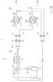
图1是执行冷却操作和加热操作的空调的制冷循环的框图;1 is a block diagram of a refrigeration cycle of an air conditioner that performs a cooling operation and a heating operation;
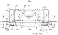
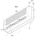
图2是根据实施例的空调的室内单元的示例性示图;FIG. 2 is an exemplary diagram of an indoor unit of an air conditioner according to an embodiment;
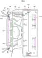
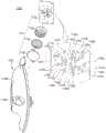
图3是图2中所示的室内单元的侧截面图;Fig. 3 is a side sectional view of the indoor unit shown in Fig. 2;
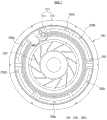
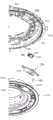
图4是沿着图3中I-I线截取的平面截面图;Fig. 4 is a plan sectional view taken along line I-I in Fig. 3;
图5是沿着图3中II-II线截取的平面截面图;Fig. 5 is a plan sectional view taken along line II-II in Fig. 3;
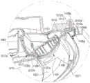
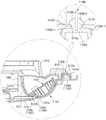
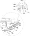
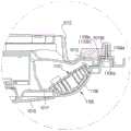
图6是图3的虚线圆形部分的放大图;FIG. 6 is an enlarged view of the dotted circular portion of FIG. 3;
图7是根据实施例的气流控制单元的示例性示图;7 is an exemplary diagram of an airflow control unit according to an embodiment;
图8是根据实施例的气流控制单元的示例性示图;8 is an exemplary diagram of an airflow control unit according to an embodiment;
图9是根据实施例的空调的控制框图;9 is a control block diagram of an air conditioner according to an embodiment;
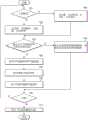
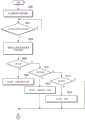
图10根据实施例的空调的控制方法的示例;10 is an example of a control method of an air conditioner according to an embodiment;
图11是按照根据实施例的空调的气流速度信息和气流方向信息而设定辅助风扇的RPM的示例性示图;11 is an exemplary diagram of setting an RPM of an auxiliary fan according to airflow speed information and airflow direction information of the air conditioner according to the embodiment;
图12、图13、图14A、图14B和图15是根据实施例的空调的控制高速模式中的气流的示例性示图;12, 13, 14A, 14B, and 15 are exemplary diagrams of controlling airflow in a high-speed mode of an air conditioner according to an embodiment;
图16是根据实施例的空调的控制方法的示例;16 is an example of a control method of an air conditioner according to an embodiment;
图17A和图17B是通过可变地控制在空调的室内单元中设置的多个辅助风扇的RPM而形成不同气流图案的实施例的示图;17A and 17B are diagrams of an embodiment of forming different airflow patterns by variably controlling the RPMs of a plurality of auxiliary fans provided in an indoor unit of an air conditioner;
图18A和图18B是通过可变地启动或关闭在空调的室内单元中设置的多个辅助风扇而形成不同气流图案的实施例的示图;18A and 18B are diagrams of an embodiment of forming different airflow patterns by variably activating or deactivating a plurality of auxiliary fans provided in an indoor unit of an air conditioner;
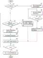
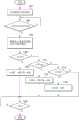
图19是根据实施例的空调的除霜操作的控制流程图;19 is a control flowchart of a defrosting operation of the air conditioner according to the embodiment;
图20是根据实施例的空调调整在除霜操作期间的气流示例性示图;20 is an exemplary diagram of an air conditioner adjusting airflow during a defrost operation, according to an embodiment;
图21是根据实施例的空调的控制流程图;21 is a control flowchart of an air conditioner according to an embodiment;
图22是根据实施例的空调的控制流程图;22 is a control flow diagram of an air conditioner according to an embodiment;
图23是在根据实施例的空调中设置的气流控制单元的示例性示图;23 is an exemplary diagram of an air flow control unit provided in the air conditioner according to the embodiment;
图24是根据实施例的空调的控制框图;24 is a control block diagram of an air conditioner according to an embodiment;
图25是根据实施例的空调控制流程图;25 is an air conditioning control flow diagram according to an embodiment;
图26和图27是在根据实施例的空调中设置的室内单元中的气流的示例性示图;26 and 27 are exemplary diagrams of air flow in an indoor unit provided in the air conditioner according to the embodiment;
图28和图29是根据实施例的空调的室内单元的示例性示图;28 and 29 are exemplary views of an indoor unit of an air conditioner according to an embodiment;
图30和图31是根据实施例的空调的室内单元的示例性示图;30 and 31 are exemplary views of an indoor unit of an air conditioner according to an embodiment;
图32和图33是根据实施例的空调的室内单元的示例性示图;32 and 33 are exemplary views of an indoor unit of an air conditioner according to an embodiment;
图34和图35是根据实施例的空调的室内单元的示例性示图;34 and 35 are exemplary views of an indoor unit of an air conditioner according to an embodiment;
图36是示出根据实施例的空调的扇叶的状态以及被排放气流根据扇叶的状态的形式的示图;36 is a diagram illustrating a state of a fan blade of an air conditioner according to an embodiment and a form of a discharged airflow according to the state of the fan blade;
图37A和图37B是示出通过可变地控制在空调的室内单元中设置的多个扇叶的摆动/固定而形成可变气流图案的实施例的示图;37A and 37B are diagrams illustrating an embodiment in which a variable airflow pattern is formed by variably controlling swing/fixation of a plurality of blades provided in an indoor unit of an air conditioner;
图38A和图38B是示出通过可变地控制在空调的室内单元中设置的多个扇叶的打开/关闭而形成可变气流图案的实施例的示图;38A and 38B are diagrams illustrating an example of forming a variable airflow pattern by variably controlling the opening/closing of a plurality of blades provided in an indoor unit of an air conditioner;
图39A和图39B是示出根据实施例的空调的气流循环模式的效果的示图;39A and 39B are diagrams illustrating effects of an air circulation mode of an air conditioner according to an embodiment;
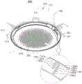
图40是根据实施例的空调的透视图;40 is a perspective view of an air conditioner according to an embodiment;
图41是从底部观察的根据实施例的空调的平面图;41 is a plan view of the air conditioner according to the embodiment viewed from the bottom;
图42是根据实施例的空调的室内单元的下壳体被移除的状态的平面图;42 is a plan view of a state in which the lower case of the indoor unit of the air conditioner according to the embodiment is removed;
图43是根据实施例的空调的分解透视图;43 is an exploded perspective view of an air conditioner according to an embodiment;
图44是沿着图41中标记的II-II线截取的侧截面图;Figure 44 is a side sectional view taken along line II-II marked in Figure 41;
图45是在图44中标记的“O”部分的放大图;Figure 45 is an enlarged view of the portion marked "O" in Figure 44;
图46是根据实施例的空调的显示单元的分解透视图;46 is an exploded perspective view of a display unit of an air conditioner according to an embodiment;
图47是根据实施例的空调的显示单元的放大图;47 is an enlarged view of a display unit of an air conditioner according to an embodiment;
图48是沿着图40中标记的I-I线截取的截面图的示例;Figure 48 is an example of a cross-sectional view taken along line I-I marked in Figure 40;
图49是根据实施例的空调的一部分的分解图;49 is an exploded view of a portion of an air conditioner according to an embodiment;
图50是沿着图40中标记的I-I线截取的截面图的示例;Figure 50 is an example of a cross-sectional view taken along line I-I marked in Figure 40;
图51是沿着图40中标记的I-I线截取的截面图的示例;Figure 51 is an example of a cross-sectional view taken along line I-I marked in Figure 40;
图52是沿着图40中标记的I-I线截取的截面图的示例;Figure 52 is an example of a cross-sectional view taken along line I-I marked in Figure 40;
图53是示出图40中所示的空调的实施例的示图;FIG. 53 is a diagram showing an embodiment of the air conditioner shown in FIG. 40;
图54是根据实施例的空调的室内单元的控制框图;54 is a control block diagram of an indoor unit of an air conditioner according to an embodiment;
图55是示出用于可视地表示根据实施例的空调中的被排放气流的方向的控制算法的操作流程图;55 is an operational flowchart illustrating a control algorithm for visually representing the direction of the discharged airflow in the air conditioner according to the embodiment;
图56A、图56B和图56C示出通过根据实施例的空调可视地表示被排放气流的方向的示例;56A, 56B, and 56C illustrate an example of visually representing the direction of the discharged airflow by the air conditioner according to the embodiment;
图57A、图57B和图57C示出通过根据实施例的空调可视地表示被排放气流的方向的示例;57A, 57B, and 57C illustrate an example in which the direction of the discharged airflow is visually represented by the air conditioner according to the embodiment;
图58是示出根据实施例的空调的室内单元的透视图;58 is a perspective view illustrating an indoor unit of an air conditioner according to an embodiment;
图59示出用于可视地表示根据实施例的空调中的被排放气流的强度的控制算法的操作流程图;59 shows an operational flow chart of a control algorithm for visually representing the intensity of the discharged airflow in the air conditioner according to the embodiment;
图60A和图60B是示出根据实施例的用于可视地表示空调中的被排放气流的方向和强度的第一控制算法的操作流程图;Figures 60A and 60B are operational flow diagrams illustrating a first control algorithm for visually representing the direction and intensity of exhaust air flow in an air conditioner, according to an embodiment;
图61A和图61B是示出表示根据实施例的用于可视地空调中的被排放气流的方向和强度的第二控制算法的操作流程图;61A and 61B are operational flow diagrams illustrating a second control algorithm representing the direction and intensity of exhaust air flow in visually air conditioning according to an embodiment;
图62A和图62B是示出根据另一实施例的用于可视地表示空调中的被排放气流的方向和强度的第三控制算法的操作流程图;Figures 62A and 62B are operational flow charts illustrating a third control algorithm for visually representing the direction and intensity of exhaust air flow in an air conditioner, according to another embodiment;
图63是示出根据实施例的空调的室内单元的透视图;63 is a perspective view illustrating an indoor unit of an air conditioner according to an embodiment;
图64是示出根据实施例的空调的室内单元的透视图;64 is a perspective view illustrating an indoor unit of an air conditioner according to an embodiment;
图65是示出根据实施例的空调的室内单元的透视图;以及65 is a perspective view illustrating an indoor unit of an air conditioner according to an embodiment; and
图66是示出根据实施例的空调的室内单元的透视图。FIG. 66 is a perspective view illustrating an indoor unit of an air conditioner according to an embodiment.
具体实施方式Detailed ways
现在,将详细介绍在附图中示出其示例的实施例,其中,遍及说明书,相同的附图标号指相同的元件。以下通过参照示图描述实施例以解释本公开。Reference will now be made in detail to embodiments, examples of which are illustrated in the accompanying drawings, wherein like reference numerals refer to like elements throughout the specification. The embodiments are described below to explain the present disclosure by referring to the figures.
在以下进行具体实施方式之前,提出遍及该专利文献所使用的特定词汇和短语的定义可能是有利的:术语“包括”和“包含”以及其衍生词指“包括”,但不限制;术语“或”是包括的,指“和/或”;短语“与…关联”和“关联于”以及其衍生可指包括、被包括“在…内”、“与…互相连接”、“含有”、“被含有在…内”、“连接到…”或“与…连接”、“结合到…”或“与…结合”、“与…可连通”、“与…协作”、“交织”、“并置”、“接近…”、“接合到…”或“与…结合”、“具有…”、“具有…的特性”等;术语“控制器”指控制至少一种操作的装置、系统或其部件,该装置可在硬件、固件或软件或者它们的至少两者的某些组合中实施。应当注意的是,与任意具体控制器相关联的功能可被局部地或较远地集中或分配。遍及该专利文献,可提供对于特定词汇和短语的定义,本领域的普通技术人员应当理解:在许多,如果不是大多数示例中,该定义应用于该被定义的词汇和短语之前以及将来的使用。Before proceeding to the detailed description below, it may be beneficial to provide definitions of certain words and phrases used throughout this patent document: the terms "including" and "comprising" and their derivatives mean "including," but not limiting; or" is inclusive and means "and/or"; the phrases "associated with" and "associated with" and derivatives thereof may mean including, being included in, "interconnected with", "containing", "contained within", "connected to" or "connected with", "coupled to" or "combined with", "communicable with", "cooperating with", "interwoven", " "juxtaposed", "proximate to", "engaged to" or "combined with", "having", "having the characteristics of", etc.; the term "controller" refers to a device, system or components thereof, the apparatus may be implemented in hardware, firmware or software, or some combination of at least two of them. It should be noted that the functions associated with any particular controller may be centralized or distributed locally or remotely. Throughout this patent document, definitions for certain words and phrases may be provided, those of ordinary skill in the art should understand that in many, if not most instances, such definitions apply to prior and future uses of the defined words and phrases .
在该专利文献中以下论述的图1至图66以及用于描述本公开的原理的各种实施例仅借助于图示且不应当解释为按照任意方式限制本公开的范围。本领域的普通技术人员将理解:本公开的原理可按照任意适当配置的洗衣机技术实施。以下,将详细参照附图描述本公开的实施例。1 through 66, discussed below in this patent document, and the various embodiments used to describe the principles of the present disclosure are by way of illustration only and should not be construed to limit the scope of the disclosure in any way. Those of ordinary skill in the art will understand that the principles of the present disclosure may be implemented in any suitably configured washing machine technology. Hereinafter, embodiments of the present disclosure will be described in detail with reference to the accompanying drawings.
图1是执行冷却操作和加热操作的空调的制冷循环的框图。FIG. 1 is a block diagram of a refrigeration cycle of an air conditioner that performs a cooling operation and a heating operation.
如图1所示,空调1是能够执行用于冷却多个空气被调节空间的冷却操作以及用于加热多个空气被调节空间的加热操作两者的设备。空调1包括至少一个室外单元100和多个室内单元200a和200b。As shown in FIG. 1 , the
室外单元100包括压缩机110、室外热交换器120、膨胀阀130、室外风扇140、第一检测单元150、四通阀160、储液器(accumulator)170以及油分离器180。多个室内单元200a和200b分别包括室内热交换器210、主风扇220、辅助风扇230以及第二检测单元240。制冷剂管将室外单元100连接到室内单元200a和200b,制冷剂循环通过制冷剂管。The
压缩机110压缩制冷剂且将处于高温、高压气体状态的被压缩的制冷剂排放。例如,在冷却操作期间,压缩机110将处于高温、高压气体状态的制冷剂排放到室外热交换器120。The
室外热交换器120执行在制冷剂和室外空气之间的热交换。例如,在冷却操作期间,室外热交换器120通过散发热来冷凝从压缩机110引入的制冷剂。这里,制冷剂处于高温、高压气体状态的相态被转换成制冷剂处于高温、高压液体状态。The
膨胀阀130包括第一膨胀阀131和第二膨胀阀132。The
第一膨胀阀131和第二膨胀阀132分配从室外热交换器120通过第一分配管供给的制冷剂,以分别将被分配的制冷剂供给到第一室内单元200a和第二室内单元200b。这里,第一膨胀阀131和第二膨胀阀132还可用作可控制开口以用于控制制冷剂被供给到第一室内单元200a和第二室内单元200b的流量的流量控制阀。第一膨胀阀131可将室外热交换器120连接到第一室内单元200a的室内热交换器210,以控制供给到第一室内单元200a的制冷剂的流量,第二膨胀阀132可将室外热交换器120连接到第二室内单元200b的室内热交换器210,以控制供给到第二室内单元200b的制冷剂的流量。The
在冷却操作期间,膨胀阀130使从室外热交换器120引入的制冷剂的压力和温度降低。换句话说,已通过膨胀阀130的制冷剂从高温、高压液体状态改变为低温、低压液体状态。膨胀阀130的膨胀动作允许制冷剂在多个室内单元200a和200b的室内热交换器210中容易蒸发。此外,其压力和温度降低了的制冷剂被转移到室内热交换器210。这里,膨胀阀130还可使用细长管(capillary tube)来实现。During the cooling operation, the
室外风扇140设置在室外热交换器120的一部分处且通过风扇马达旋转以辅助热交换,从而强制地吹在室外热交换器120周围的空气。The
第一检测单元150包括:第一温度检测单元151,检测室外热交换器120的温度;第二温度检测单元152,检测室外单元100周围的室外温度。这里,第一温度检测单元151可设置在室外热交换器120的输出侧,还可设置在室外热交换器120的输入侧,并且还可设置在室外热交换器120之间的中间处。The
室外单元100还包括第二分配管以收集从第一室内单元200a和第二室内单元200b供给的制冷剂并将制冷剂供给到压缩机110。这里,还可使用具有阀的分配器,代替第一分配管和第二分配管。The
四通阀160是根据操作(冷却或加热)来切换制冷剂流动方向的流动切换阀。在加热操作期间,四通阀160可将从压缩机110排放的高温、高压制冷剂引导到第一室内单元200a和第二室内单元200b且将室外热交换器120的低温、低压制冷剂引导到储液器170。这里,室外热交换器120用作蒸发器,第一室内单元200的第一室内热交换器210和第二室内单元200b的第二室内热交换器210用作冷凝器。The four-
另外,在冷却操作期间,四通阀160可将从压缩机110排放的高温、高压制冷剂引导到室外热交换器120且将第一室内单元200a和第二室内单元200b的低温、低压制冷剂引导到储液器170。这里,室外热交换器120用作冷凝器,第一室内单元200a和第二室内单元200b用作蒸发器。In addition, during the cooling operation, the four-
储液器170设置在压缩机110的吸入侧,以将来自被引入到压缩机110的制冷剂中的处于液体状态的未气化的制冷剂分离,从而防止处于液体状态的制冷剂被排放到压缩机110。通过此,可防止压缩机110损坏。The
油分离器180将与从压缩机110排放的制冷剂的蒸气混合的油分离并将油返回到压缩机110。通过这种方式,在室外热交换器120和室内热交换器210的表面上形成油膜,由此防止热传递效果劣化且防止润滑作用由于压缩机110中缺少润滑油而劣化。The
空调1还包括连接阀V1、V2、V3和V4,以将室外单元100的制冷剂管连接到第一室内单元200a和第二室内单元200b的制冷剂管。The
第一室内单元200a和第二室内单元200b为相同的装置,且第一室内单元200a和第二室内单元200b分别包括室内热交换器210、主风扇220、辅助风扇230和第二检测单元240。The first
第一室内单元200a和第二室内单元200b的室内热交换器210分别设置在空气被调节空间中。在冷却操作期间,室内热交换器210通过由从第一膨胀阀131和第二膨胀阀132引入的制冷剂的蒸发所导致的热吸收而与空气被调节空间的空气进行热交换。这里,制冷剂处于低温、低压液体状态的相态被转换成制冷剂处于低温、低压气体状态。The
主风扇220设置在室内热交换器210中。主风扇220通过第一马达旋转,以从空气被调节空间抽吸空气且强制地使在室内热交换器210中热交换后的空气被吹至该空气被调节空间。The
辅助风扇230设置在室内热交换器210中。辅助风扇230通过第二马达旋转,以抽吸被排放到空气被调节空间的一些空气,由此调节被排放到空气被调节空间的空气的流动方向。The
第二检测单元240包括:第三温度检测单元241,检测连接到室内热交换器210的制冷剂管中的连接到室内热交换器210的入口的制冷剂管的温度;第四温度检测单元242,检测连接到室内热交换器210的制冷剂管中的连接到室内热交换器210的出口的制冷剂管的温度;第五温度检测单元243,设置在室内单元200中,以检测空气被调节空间的温度。这里,在对于过加热(overheating)或过冷却(overcooling)的控制中,可使用分别通过第三温度检测单元241和第四温度检测单元242检测室内热交换器210的入口和出口的温度。The
在加热操作期间,空调1切换四通阀160的流动通道,以将从压缩机110排放的高温、高压制冷剂引导到室内热交换器210且将室内单元200a和200b的低温、低压制冷剂引导到储液器170。这里,室外热交换器120用作蒸发器,且室内热交换器210用作冷凝器。During the heating operation, the
在加热操作期间,在空调中发生冷凝物(condensate)形成在室外热交换器的表面上的现象,为此,执行用于去除室外热交换器上的霜的除霜模式。这里,除霜模式是通过由于在冷却操作的循环中使室外热交换器用作冷凝器的操作所导致的从室外热交换器散发的热而去除室外热交换器上的霜的模式。During the heating operation, a phenomenon in which condensate is formed on the surface of the outdoor heat exchanger occurs in the air conditioner, and for this reason, a defrosting mode for removing frost on the outdoor heat exchanger is performed. Here, the defrosting mode is a mode in which frost on the outdoor heat exchanger is removed by heat radiated from the outdoor heat exchanger due to the operation of using the outdoor heat exchanger as a condenser in a cycle of cooling operation.
空调还可包括基于冷却操作、加热操作和操作模式而控制室内单元和室外单元的驱动模块。以下将描述驱动模块的构造。The air conditioner may further include a driving module that controls the indoor unit and the outdoor unit based on the cooling operation, the heating operation, and the operation mode. The configuration of the drive module will be described below.
另外,空调还可包括设置在室内单元200或遥控器(未示出)中的用户界面,以接收来自用户的命令和输出操作信息。这里,遥控器可设置为有线型或无线型。In addition, the air conditioner may further include a user interface provided in the
在以上描述中,已描述了能够冷却和加热的多联式空调(multi-type airconditioner)。然而,能够冷却和加热的多联式空调仅为空调的示例,并不排除仅能够冷却的单型空调(single-type air conditioner)或能够冷却和加热的单型空调。In the above description, a multi-type air conditioner capable of cooling and heating has been described. However, the multi-type air conditioner capable of cooling and heating is only an example of an air conditioner, and a single-type air conditioner capable of cooling only or a single-type air conditioner capable of cooling and heating is not excluded.
图2是根据实施例的空调的室内单元200-1的示例性示图且是形成为圆形且安装在天花板上的吸顶式室内单元(ceiling-mounted indoor unit)的示例性示图。FIG. 2 is an exemplary diagram of an indoor unit 200-1 of an air conditioner according to an embodiment and is an exemplary diagram of a ceiling-mounted indoor unit formed in a circular shape and mounted on a ceiling.
如图2所示,室内单元200-1可在其至少一部分埋设到天花板C中的同时被固定和安装。As shown in FIG. 2, the indoor unit 200-1 may be fixed and installed while at least a part thereof is buried in the ceiling C. As shown in FIG.
室内单元200-1包括具有吸入部250a和排放部250b的壳体250。这里,当沿竖直方向观察天花板的表面时,壳体250具有近似圆形。此外,壳体250包括设置在天花板C中的第一壳体251、结合到第一壳体251的下部的第二壳体252和结合到第二壳体252的下部的第三壳体253。The indoor unit 200-1 includes a
包括多个吸入孔的吸入部250a可设置在第三壳体253的中央部分处,以抽吸空气。用于滤除被抽吸到吸入部250a中的空气内的灰尘的过滤部254可设置在吸入部250a上。包括排放空气所通过的多个排放孔的排放部250b可设置在吸入部250a的外侧部分。当沿竖直方向朝向天花板的表面观察时,排放部250b可具有近似圆形。A
图3是图2中所示的室内单元的侧截面图。FIG. 3 is a side sectional view of the indoor unit shown in FIG. 2 .
如图3所示,用于滤除被抽吸到吸入部250a中的空气内的灰尘的过滤部254可设置在第三壳体253的底表面上。As shown in FIG. 3 , a
另外,第三壳体253可具有康达曲面部(Coanda curved surface portion)253a,以引导通过排放部250b排放的空气。通过排放部250b排放的空气通过康达效应沿着康达曲面部253a的表面流动,归因于此,通过康达曲面部253a的表面的形式来确定气流方向。换句话说,当康达曲面部253a的坡度平缓时,被排放气流的角度也平缓。相反地,当康达曲面部253a的坡度陡峭时,被排放气流的角度也变大。In addition, the
在以上结构中的室内单元200-1从下部吸入空间被调节空间的空气、对该空气进行热交换且将空气再次排放到下部。这里,室内单元200-1可抽吸灰尘被过滤部254滤除的空气。此外,室内单元200-1可引导通过排放部250b排放的空气在与康达曲面部253a紧密接触的同时流动。The indoor unit 200-1 in the above structure sucks the air of the space-conditioned space from the lower part, exchanges heat with the air, and discharges the air to the lower part again. Here, the indoor unit 200 - 1 may suck the air whose dust is filtered by the
室内单元200-1包括设置在壳体250中的室内热交换器210、使空气流动的主风扇220和辅助风扇230以及流动通道部260。The indoor unit 200 - 1 includes an
室内热交换器210可放置在设置于壳体250中的托盘225上。托盘255储存在室内热交换器210中产生的冷凝物。当沿竖直方向朝向天花板的表面观察时,室内热交换器210可具有近似圆形。The
图4是沿着图3的I-I线截取的平面截面图。如图4所示,室内热交换器210包括:管212,制冷剂流动通过管212;集管(header)211,该集管211连接到外部制冷剂管以将制冷剂供给到管212或从管212回收制冷剂。热交换翅片可设置在管212中,以扩大散热面积。管212可具有圆形。FIG. 4 is a plan cross-sectional view taken along line I-I of FIG. 3 . As shown in FIG. 4 , the
主风扇220可设置在室内热交换器210的径向内部中。主风扇220可以是沿旋转轴向吸入空气以沿径向排放空气的离心风扇。室内单元200-1可包括第一马达(图3中的221)以将驱动力传递到主风扇220。The
室内单元200-1还包括用于控制气流方向的气流控制单元(AP,指图3的230和260)。气流控制单元AP中的至少一个可设置在壳体中,或其中的多个气流控制单元AP可按照预定间隔设置。该实施例是三个气流控制单元AP按照120°的间隔设置的情况。The indoor unit 200-1 further includes an airflow control unit (AP, refer to 230 and 260 in FIG. 3 ) for controlling the airflow direction. At least one of the airflow control units AP may be provided in the housing, or a plurality of airflow control units AP therein may be provided at predetermined intervals. This embodiment is a case where three airflow control units AP are arranged at intervals of 120°.
气流控制单元AP可抽吸排放部250b周围的空气。当吸入排放部250b周围的空气时,气流控制单元AP可从与被排放气流的方向偏离的一个方向抽吸空气。气流控制单元AP可包括至少一个辅助风扇230、流动通道部260和第二马达231,以将驱动力提供到至少一个辅助风扇230。The airflow control unit AP may suck air around the
图5是沿着图3的II-II线截取的平面截面图。如图5所示,辅助风扇230产生用于吸入排放部250b周围的空气的吸入力。此外,通过吸入力抽吸周围的空气,且空气的压力改变。此外,辅助风扇230改变通过排放部250b排放的气流图案,以形成各种形式的气流图案。FIG. 5 is a plan cross-sectional view taken along line II-II of FIG. 3 . As shown in FIG. 5 , the
流动通道部260形成被抽吸的空气流动所通过的流动通道。也就是说,流动通道部260引导被抽吸的空气的流动。The
多个辅助风扇230具有相同的结构,因此将仅描述一个辅助风扇230。尽管在本实施例中离心风扇用作辅助风扇230,但是辅助风扇230不限于此,根据设计规格,包括轴流式风扇、横流式风扇、混合流式风扇等的各种风扇可用作辅助风扇230。The plurality of
图6是图3的虚线圆形部分0的放大图。如图6所示,辅助风扇230设置在箱体232中,根据从第二马达231传递的驱动力调整辅助风扇230的旋转速度(例如,按照每分钟转数(RPM)测量)。辅助风扇230可通过旋转控制在排放部250b周围被抽吸的空气的量。此外,辅助风扇230可通过控制在排放部250b周围被抽吸的空气的量而控制被排放气流的方向。这里,控制被排放气流的方向包括控制被排放气流的角度。FIG. 6 is an enlarged view of the dotted circular portion 0 of FIG. 3 . As shown in FIG. 6 , the
流动通道部260包括流动通道,该流动通道将入口部260a连接到出口部260b,该入口部260a包括入口以抽吸排放部250b周围的空气,该出口部260b包括出口以排放被抽吸的空气。这里,入口部260a可形成在第三壳体253的康达曲面部253a上,出口部260b可在与入口部260a的相对侧处设置在排放部250b周围。具体地,出口部260b可形成在箱体232上。The
流动通道部260可包括:沿周向形成在壳体250的外部以与入口部260连通的第一流动通道261、被构造成从第一流动通道261朝向径向内部延伸的第二流动通道262和形成在箱体232中的第三流动通道263。因此,被抽吸通过入口部260a的空气可流经第一流动通道261、第二流动通道262和第三流动通道263且通过出口部260b排放。The
气流控制单元AP可沿被排放空气流动的方向A1的相反方向排放被抽吸的空气,可扩大被排放气流的角度,且还可便于控制气流。也就是说,如图6所示,假定在气流控制单元AP的多个辅助风扇230未工作时被排放气流的方向为方向A1,则气流控制单元AP的多个辅助风扇230可操作为从与方向A1偏离的一个方向抽吸空气,由此将被排放气流的方向切换到方向A2。The air flow control unit AP may discharge the sucked air in the opposite direction of the flow direction A1 of the discharged air, may enlarge the angle of the discharged air flow, and may also facilitate the control of the air flow. That is, as shown in FIG. 6 , assuming that the direction of the discharged air flow is the direction A1 when the plurality of
另外,根据由辅助风扇230抽吸的空气的量,可调整被排放气流的角度的切换。也就是说,当由辅助风扇230抽吸的空气的量大时,被排放气流的角度可被切换成小角度,当由辅助风扇230抽吸的空气的量小时,被排放气流的角度可被切换成大角度。这里,被排放气流的角度是相对于天花板的表面而言。也就是说,被排放气流的角度在与天花板的表面平行的水平方向上为0°且在与天花板的表面垂直的方向(即,法线方向)上为90°。In addition, according to the amount of air sucked by the
气流控制单元AP可沿被排放气体流动的方向A1的相反方向排放被抽吸的空气。通过此,被排放气流的角度可扩大,可进一步便于控制气流。气流控制单元AP的辅助风扇230从排放部250b的径向外部吸入空气,以使被排放气流从排放部250b的径向中央部分向径向外部宽广地传播。The airflow control unit AP may discharge the suctioned air in a direction opposite to the direction A1 of the flow of the discharged gas. Through this, the angle of the discharged airflow can be enlarged, and the airflow control can be further facilitated. The
根据实施例的空调的室内单元200-1即使在没有排放部的扇叶结构的情况下也可控制被排放气流。也就是说,尽管在传统空调的室内单元中扇叶设置在排放部中且通过扇叶的旋转控制被排放气流,但是根据实施例的空调即使在没有设置在室内单元的排放部上的扇叶的情况下也可控制被排放气流的形式。这里,被排放气流的形式可包括被排放气流的方向和被排放气流的图案。因此,因为扇叶没有干涉被排放空气,因此被排放空气的量可增加且使空气流动的噪声可减小。The indoor unit 200-1 of the air conditioner according to the embodiment can control the air flow to be discharged even without the fan blade structure of the discharge portion. That is, although in the indoor unit of the conventional air conditioner, the fan blade is provided in the discharge portion and the air flow to be discharged is controlled by the rotation of the fan blade, the air conditioner according to the embodiment even has no fan blade provided on the discharge portion of the indoor unit. The form of the air flow to be discharged can also be controlled. Here, the form of the discharged airflow may include a direction of the discharged airflow and a pattern of the discharged airflow. Therefore, since the fan blades do not interfere with the exhausted air, the amount of exhausted air can be increased and the noise that makes the air flow can be reduced.
另外,尽管传统空调的室内单元的排放部可能为了使扇叶旋转仅具有直线形状,但是根据实施例的空调的室内单元可形成为圆形。因此,壳体、热交换器等也可形成为圆形,由此不仅通过差异设计改善了美感,而且还在考虑到主风扇通常具有圆形状时确保自然气流和减少压力损失,因而结果改善了空调的冷却或加热性能。In addition, although the discharge portion of the indoor unit of the conventional air conditioner may only have a linear shape for rotating the fan blades, the indoor unit of the air conditioner according to the embodiment may be formed in a circular shape. Therefore, the casing, heat exchanger, etc. can also be formed in a circular shape, whereby not only the aesthetics is improved by the differential design, but also the result is improved considering that the main fan usually has a circular shape to ensure natural airflow and reduce pressure loss The cooling or heating performance of an air conditioner.
实施例中的流动通道部260的结构仅仅为示例,流动通道部260可为任意结构、形状和布置,只要流动通道部260将入口部260a连接到出口部260b即可。The structure of the
与上述情况相关的,将参照图7和图8描述气流控制单元AP的变型实施例。In relation to the above-mentioned situation, a modified embodiment of the airflow control unit AP will be described with reference to FIGS. 7 and 8 .
图7是根据实施例的气流控制单元AP1的示例性示图。此外,相同的附图标号将赋予来自上述图2的相同元件,且将省略对其的描述。FIG. 7 is an exemplary diagram of the airflow control unit AP1 according to the embodiment. In addition, the same reference numerals will be assigned to the same elements from the above-described FIG. 2 , and descriptions thereof will be omitted.
如图7所示,空调的室内单元200-1的气流控制单元AP1可将在排放部250b周围被抽吸的空气排放到壳体250中,而不是将空气朝向排放部250b排放。气流控制单元AP1根据气流方向将在排放部250b周围被抽吸的空气朝向室内热交换器210的上游排放。按照这种方式排放的空气通过流经室内热交换器210被再次热交换,随后最终通过排放部250b排放到室内空间。As shown in FIG. 7 , the airflow control unit AP1 of the indoor unit 200-1 of the air conditioner may discharge air drawn around the
辅助风扇230设置在箱体232中,根据从第二马达231传递的驱动力来调整辅助风扇230的RPM。辅助风扇230可通过旋转控制在排放部250b周围被抽吸的空气的量。辅助风扇230可通过控制在排放部250b周围被抽吸的空气的量而控制被排放气流的方向。这里,控制被排放气流的方向包括控制被排放气流的角度。The
流动通道部260包括:入口部260a,该入口部260a形成在第三壳体253中且被构造成抽吸在排放部250b周围的空气,以将在排放部250b周围被抽吸的空气排放到壳体250的内部;出口部260b,该出口部260b形成在壳体250中且被构造成排放被抽吸的空气。The
流动通道部260包括:第一流动通道261,该第一流动通道261沿周向形成且被构造成与入口部260a连通;第二流动通道262,该第二流动通道262被构造成从第一流动通道261向径向内部延伸;第三流动通道263,该第三流动通道263形成在箱体232中;第四流动通道264,该第四流动通道264被构成从第三流动通道263向壳体250的内部延伸且与出口部260b连通。因此,被抽吸通过入口部260a的空气可流经第一流动通道261、第二流动通道262、第三流动通道263以及第四流动通道264且通过出口部260b被排放。The
图8是根据实施例的气流控制单元AP2的示例性示图。此外,相同的附图标号将赋予来自上述图2的相同元件,且将省略对其的描述。FIG. 8 is an exemplary diagram of an airflow control unit AP2 according to an embodiment. In addition, the same reference numerals will be assigned to the same elements from the above-described FIG. 2 , and descriptions thereof will be omitted.
如图8所示,气流控制单元AP2可被设置成从排放部250b的径向内部抽吸空气,而不是从排放部250b的径向外部吸入空气。As shown in FIG. 8 , the air flow control unit AP2 may be configured to draw air from the radially inner portion of the
辅助风扇230可设置在箱体232中,根据从第二马达231传递的驱动力来调整辅助风扇230的RPM。辅助风扇230可通过旋转控制在排放部250b周围被抽吸的空气的量。也就是说,辅助风扇230可通过吸入在排放部250b周围的空气而控制被排放气流的方向。这里,控制被排放气流的方向包括控制被排放气流的角度。The
流动通道部260包括:入口部260a,该入口部260a设置在排放部250b的径向内部处,即,设置在第三壳体的安装有过滤部254的表面253b上,以抽吸在排放部250b周围的空气;出口部260b,该出口部260b将通过入口部260a被抽吸的空气朝向室内热交换器210传送。此外,流动通道部260可包括与入口部260a连通的第一流动通道和同时向径向内部延伸且与出口部260b连通的第二流动通道。The
如在上述情况中,气流控制单元AP2从排放部250b的径向内部抽吸空气,以使被排放气流可从排放部250b的径向外部朝向排放部250b的径向中央部集中。As in the above case, the airflow control unit AP2 draws air from the radially inner portion of the
图9是根据实施例的空调的控制框图。FIG. 9 is a control block diagram of the air conditioner according to the embodiment.
图9中所示的空调可以是单型加热空调、单型冷却空调。单型冷却加热空调、多型加热空调、多型冷却空调和多型冷却加热空调中的任一种。此外,室内单元可以是圆形吸顶式室内单元、四边形吸顶式室内单元或壁挂式室内单元和立式室内单元中的任意一种。The air conditioner shown in FIG. 9 may be a single type heating air conditioner, a single type cooling air conditioner. Any of single type cooling heating air conditioner, multi type heating air conditioner, multi type cooling air conditioner and multi type cooling heating air conditioner. In addition, the indoor unit may be any one of a circular ceiling-type indoor unit, a quadrangular ceiling-type indoor unit, or a wall-mounted indoor unit and a vertical indoor unit.
空调包括室外单元100和室内单元200,空调的室外单元100和室内单元200彼此连通。换句话说,室外单元100和室内单元200发送和接收彼此的信息,即,室外单元100的信息和室内单元200的信息。The air conditioner includes an
空调的室外单元100包括用于控制诸如第一检测单元150、压缩机和膨胀阀等的各种负载的第一驱动模块190。此外,室内单元200包括用于控制诸如第二检测单元240、输入单元270、显示单元280、主风扇220以及辅助风扇230等的各种负载的第二驱动模块290。The
为了区分室外单元的元件与室内单元的元件,“第一”将被赋予室外单元的元件,“第二”相对于具有相同名称的元件将被赋予室内单元的元件。In order to distinguish the elements of the outdoor unit from the elements of the indoor unit, "first" will be assigned to the element of the outdoor unit, and "second" will be assigned to the element of the indoor unit with respect to the element having the same name.
首先,将描述室外单元100的元件。First, the elements of the
第一检测单元150包括用以检测在室外热交换器120中流动的制冷剂的温度的第一温度检测单元151和用于检测室外温度的第二温度检测单元152。通过第一温度检测单元151和第二温度检测单元152检测到的温度信息可用作确定除霜模式的开始和结束的信息。The
第一驱动模块190基于从室内单元200发送的室内负载信息、操作模式和工作模式以及通过室外单元100检测到的室外检测信息而驱动多个室外载荷110、130、140和160,且第一驱动模块190包括第一控制单元191、第一存储单元192、第一通信单元193和第一驱动单元194。The
第一控制单元191当接收来自室内单元200的操作命令时而控制压缩机110的启动或关闭、压缩机110的RPM、膨胀阀130的开口、室外风扇140的RPM等。这里,操作命令包括操作模式、工作模式、室内负载信息。The
操作模式包括冷却模式和加热模式,工作模式包括正常模式、高速模式和气流循环模式。室内负载信息包括目标室内温度以及检测到的室内温度。此外,当冷却操作和加热操作两者均可运行时,第一控制单元191还可检查操作模式是加热操作还是冷却操作,以控制四通阀160的流动通道的开口(opening)。The operation modes include cooling mode and heating mode, and the working modes include normal mode, high speed mode and airflow circulation mode. The indoor load information includes the target indoor temperature and the detected indoor temperature. In addition, when both the cooling operation and the heating operation are operable, the
当输入冷却操作时,第一控制单元191调整四通阀160的流动通道的开口且控制压缩机110、膨胀阀130和室外风扇140,以使制冷剂循环,由此冷却空气被调节空间。当输入加热模式时,第一控制单元191控制四通阀160的流动切换且控制压缩机110、膨胀阀130和室外风扇140,以切换制冷剂的流动,由此加热室内空间。When a cooling operation is input, the
另外,在加热操作期间,第一控制单元191可基于通过第一检测单元检测到的温度信息、压缩机操作时间信息中的至少一者而确定除霜操作的开始,且当确定了除霜模式的开始时控制除霜操作。这里,除霜操作可包括控制四通阀160的将被切换的流动通道以使制冷剂循环至除霜循环(与制冷循环相同)或操作与室外热交换器相邻安装的加热单元。In addition, during the heating operation, the
第一存储单元192存储与操作命令对应的压缩机110的RPM、膨胀阀130的开口、室外风扇140的RPM等。此外,第一存储单元192存储关于用于确定除霜操作的开始的室外热交换器在各室外温度下的温度信息和压缩机操作时间信息、存储关于在除霜操作期间辅助风扇的RPM的信息,且存储关于用于确定除霜操作的结束的除霜操作时间信息或室外热交换器在各室外温度下的温度的信息。这里,辅助风扇在除霜操作期间的RPM可被存储为与主风扇在除霜操作之前的加热操作期间的各RPM相匹配。The
第一通信单元193执行与至少一个室内单元的通信。第一通信单元193接收从至少一个室内单元200发送的操作命令和室内负载信息,且将室内负载信息和操作模式传输到第一控制单元191,将除霜模式信息传输到室内单元200。The
第一驱动单元194包括基于第一控制单元191的命令而驱动压缩机的压缩机驱动单元194a和基于第一控制单元191的命令而驱动各种阀的阀驱动单元194b。压缩机驱动单元194a可以是使设置在压缩机中的马达旋转的逆变器(inverter)驱动单元。这里,各种阀可包括膨胀阀和四通阀的至少一种。The
接下来,将描述室内单元200的构造。Next, the configuration of the
第二检测单元240包括用以检测室内空间的温度的第五温度检测单元243。The
第三检测单元244检测用户是否在室内空间和检测用户的位置。第三检测单元244包括人体传感器,该人体传感器可包括能够检测人体的任意传感器,包括近红外线传感器、红外线传感器、图像传感器等。The
第四检测单元245包括用于检测在设置在壳体的吸入部处的过滤部中的灰尘的量的传感器。The
传感器可以是间接检测灰尘量的第一马达221的电流检测单元。也就是说,电流检测单元检测在主风扇220的第一马达221中流动的电流。将驱动力施加到主风扇220的第一马达221的负载可根据被抽吸到室内单元200中空气量而变化,这里,电流检测单元检测在第一马达221中流动的电流,从而检测第一马达221的负载。The sensor may be a current detection unit of the
另外,传感器可以是直接检测灰尘量的空气压力检测单元或光学检测单元。空气压力检测单元检测被抽吸到主风扇220中的空气的压力。也就是说,空气压力检测单元检测被抽吸的空气的压力,因为被抽吸到主风扇220中的空气的压力可根据过滤部中的灰尘的量而变化。In addition, the sensor may be an air pressure detection unit or an optical detection unit that directly detects the amount of dust. The air pressure detection unit detects the pressure of the air drawn into the
随着来自用户的输入和信息的输入块(input piece)被传输到第二控制单元291,输入单元270接收包括冷却操作和加热操作的操作模式、包括正常模式、高速模式和气流循环模式的工作模式、目标室内温度以及关于气流方向和气流速度的信息。With the input from the user and the input piece of information being transmitted to the
显示单元280显示关于操作模式、工作模式、气流方向、气流速度、目标室内温度、目前检测的室内温度等的信息。The
第二驱动模块290基于通过第二检测单元240/第三检测单元244/第四检测单元245检测到的信息和被输入到输入单元270的信息来控制主风扇220和辅助风扇230的旋转,且第二驱动模块290包括第二控制单元291、第二存储单元292、第二通信单元293和第二驱动单元294。The
第二控制单元291基于通过第二通信单元293接收的信息和被输入到输入单元270的信息而控制主风扇220、辅助风扇230等的操作。The
当选择正常模式时,第二控制单元291控制主风扇220和辅助风扇230,以使具有基准气流速度和基准气流方向的气流被排放。在正常模式下,当输入气流速度信息和气流方向信息时,第二控制单元291检查与输入的气流速度信息对应的主风扇220的RPM、检查与气流方向信息对应的气流角度并基于检查到的主风扇220的RPM和气流角度来控制辅助风扇230的RPM。When the normal mode is selected, the
通过此,第二控制单元291可调节排放部250b周围被抽吸的空气的量并调整被排放气流的方向。这里,获得的辅助风扇230的RPM的值可以是基于主风扇220的RPM和气流角度的函数所得获得的值或可以是根据通过获得空气在主风扇220的每个RPM下流动所处的角度的实验中预获得且被存储的被储存值。Through this, the
当选择了高速模式或气流循环模式时,第二控制单元291通过预设的RPM控制主风扇220且在第一阶段中启动或关闭辅助风扇230或重复且变化地控制辅助风扇230的RPM,直到室内温度达到目标温度为止。此外,在室内温度已达到目标温度的第二阶段中,第二控制单元291将辅助风扇230的RPM控制为预设的RPM。也就是说,第二控制单元291将辅助风扇230在第一阶段中的RPM循环且重复地控制为第一RPM或比第一RPM高的第二RPM。When the high-speed mode or the airflow circulation mode is selected, the
另外,第二控制单元291还可在第一阶段中将辅助风扇230的RPM循环且重复地控制为第一RPM、比第一RPM高的第二RPM以及比第二RPM高的第三RPM。此外,第二控制单元291还可重复地控制辅助风扇230在第一阶段中被启动或关闭的操作。In addition, the
另外,第二控制单元291通过预设的RPM控制主风扇220且控制辅助风扇230的RPM,以使通过排放部排放的被排放气流到达用户。具体地,第二控制单元291基于由第三检测单元244检测到的信息检查用户是否在室内空间中以及用户在室内空间中的位置、检查与用户在室内空间中的位置对应的气流角度、检查与主风扇220的RPM和气流角度对应的辅助风扇230的RPM并将辅助风扇230的RPM控制为检查的RPM。In addition, the
当接收除霜操作信号时,第二控制单元291将主风扇220的操作控制为停止且控制辅助风扇230按照预设的RPM旋转。在除霜操作期间,第二控制单元291还可检查主风扇220在除霜操作之前的加热操作期间的RPM且基于检查到的主风扇220的RPM而控制辅助风扇230的RPM。When receiving the defrosting operation signal, the
另外,在除霜操作期间,第二控制单元291还可将主风扇220的操作控制为停止、基于由第三检测单元244检测到的信息检查用户是否在室内空间中且基于用户是否存在而控制辅助风扇230的操作。例如,在除霜操作期间,第二控制单元291在确定在室内空间中不存在用户时可将辅助风扇230控制为停止,且在确定在室内空间中存在用户时可操作辅助风扇230。通过此,可减少在除霜操作期间由于辅助风扇230的操作而消耗的电力。In addition, during the defrosting operation, the
另外,当输入操作命令时,第二控制单元291确定其是否为初始操作命令、当确定已输入初始操作命令时基于由第四检测单元245检测的信息而检查在过滤部中的灰尘量以及控制作为在过滤部中的检查到的初始灰尘量的第一灰尘量的存储。此外,当输入的操作命令不是初始操作命令时,第二控制单元291在执行操作的同时检查在预定循环中在过滤部中的第二灰尘量且基于检查到的第一灰尘量和第二灰尘量而将辅助风扇230的RPM控制为被补偿。In addition, when the operation command is input, the
当输入操作命令时,第二控制单元291确定操作命令是否为初始操作命令、检测当输入的操作命令被确定为是初始操作命令时检测在第一马达221中流动的电流以及控制被检测的第一电流的存储。此外,当输入的操作命令不是初始操作命令时,第二控制单元291在执行操作的同时周期性地检查第一马达221在每个预定循环中的电流且基于检查到的第一电流和第二电流而将辅助风扇230的RPM控制为被补偿。When an operation command is input, the
当确定已输入初始操作命令时,第二控制单元291检查对于通过最大RPM使第一马达221旋转的脉宽调制(PWM)的占空比(duty ratio)且控制被检查到的第一占空比的存储。此外,当输入的操作命令不是初始操作命令时,第二控制单元291周期性地检查在每个预定循环中对于通过最大RPM使第一马达221旋转的脉宽调制(PWM)的占空比且基于检查到的第二占空比和第一占空比而将辅助风扇230的RPM控制为被补偿。也就是说,主风扇220的第一马达221的最大RPM可根据过滤部中的灰尘量而变化,相应地,被施加到第一马达221的PWM信号的占空比可不同。When it is determined that the initial operation command has been input, the
第二控制单元291控制第二通信单元293以经由第二通信单元293将被输入到输入单元270的信息和由第二检测单元240检查的信息传输到室外单元。第二控制单元291可从室外单元100接收温度信息,即,关于室外温度和室外热交换器的温度的信息,并基于接收到的室外温度和室外热交换器的温度而确定除霜操作的开始且还可从室外单元100接收压缩机操作时间,以确定除霜操作的开始。The
第二存储单元292存储关于相对于在正常模式中的基准气流速度和基准气流方向的主风扇220的基准RPM和辅助风扇230的基准RPM的信息。这里,主风扇220的基准RPM和辅助风扇230的基准RPM对于各操作模式可以不同或可以相同。The
另外,在正常模式中,第二存储单元292存储关于主风扇220对于各气流速度的RPM的信息且存储关于对于各气流方向的气流角度的信息。此外,第二存储单元292还可基于主风扇220的RPM和气流角度存储关于辅助风扇230的RPM的信息。In addition, in the normal mode, the
在高度模式或气流循环模式中,第二存储单元292存储在预设的第一阶段中的主风扇220的控制信息和辅助风扇230的控制信息且存储在预设的第二阶段中的主风扇220的控制信息和辅助风扇230的控制信息。这里,控制信息可包括关于控制RPM的信息和关于控制主风扇220或辅助风扇230启动和关闭的信息。In the altitude mode or the airflow circulation mode, the
此外,主风扇220在第一阶段中的RPM和主风扇220在第二阶段中的RPM可彼此相同或彼此不同。此外,辅助风扇230在第一阶段中的RPM可以是循环重复增大和减小的RPM。辅助风扇230在第一阶段中的RPM可包括第一RPM和比第一RPM大的第二RPM,辅助风扇230在第二阶段中的RPM可与第二RPM相同。辅助风扇230在第一阶段中的RPM还可包括第一RPM、比第一RPM大的第二RPM和比第二RPM大的第三RPM。Furthermore, the RPM of the
在除霜操作期间,第二存储单元292存储关于辅助风扇的预设的RPM的信息。此外,第二存储单元292可存储关于对于主风扇220在除霜操作开始之前的加热操作期间的各RPM而言的辅助风扇230的RPM的信息。During the defrosting operation, the
在正常模式中,第二存储单元292存储关于主风扇在各气流速度下的RPM的信息且存储关于在各气流方向下的气流角度的信息。此外,第二存储单元292存储在初始操作期间的第一占空比、第一电流或第一灰尘量。这里,第一灰尘量可包括关于光量的信息、关于空气压力的信息或关于电流的信息。In the normal mode, the
第二存储单元292还可储存与第一灰尘量和第二灰尘量对应的对于辅助风扇230的RPM的补偿值。此外,第二存储单元292还可存储与第一占空比和第二占空比对应的对于辅助风扇230的RPM的补偿值。此外,第二存储单元292还可存储与第一电流和第二电流对应的对于辅助风扇230的RPM的补偿值。The
第二通信单元293可与至少一个室内单元通信。第二通信单元293将关于从室外单元100传输的除霜操作的信息传输到第二控制单元291。第二通信单元293接收室内负载信息和操作命令,以将室内负载信息和操作命令传输到室外单元的第一控制单元191。The
第二驱动单元294基于第二控制单元291的命令而驱动设置在室内单元中的各种负载。第二驱动单元294包括用以驱动主风扇220的第一马达221的主风扇驱动单元294a和用以驱动辅助风扇230的第二马达231的辅助风扇驱动单元294b。The
室外单元100的第一控制单元191和室内单元200的第二控制单元291可以是处理器、中央处理器(CPU)、微程序控制器(MCU)等等。The
室外单元100的第一存储单元192和室内单元200的第二存储单元292不仅可包括诸如随机存取存储器(RAM)、静态RAM(S-RAM)、动态RAM(D-RAM)等的易失性存储器,还可包括诸如闪速存储器、只读存储器(ROM)、可擦除可编程只读存储器(EPROM)、电EPROM(EEPROM)等的非易失性存储器。The
图10是根据实施例的控制空调的方法的示例。将参照图10描述在冷却操作期间的正常模式和高速模式的控制。FIG. 10 is an example of a method of controlling an air conditioner according to an embodiment. Control of the normal mode and the high-speed mode during the cooling operation will be described with reference to FIG. 10 .
空调检查当经由输入单元270或遥控器(未示出)输入开机(power-on)信号时的操作模式。如果操作模式为冷却操作,则驱动压缩机110且打开膨胀阀130以使被压缩机110压缩的制冷剂经由室外热交换器120和膨胀阀130向室内热交换器210移动。按照这种方式,空调使将在制冷循环中循环的制冷剂执行冷却操作。此外,当设置了四通阀160时,空调控制四通阀160的流动通道以执行冷却操作。The air conditioner checks an operation mode when a power-on signal is input via the
空调可按照各种工作模式执行冷却操作。The air conditioner can perform cooling operation according to various working modes.
在用户选择工作模式之前,空调可执行在空调被启动之前所执行的工作模式或执行默认工作模式(即,正常模式)。这里,工作模式可包括正常模式和高速模式。Before the user selects the operation mode, the air conditioner may perform the operation mode performed before the air conditioner is activated or perform the default operation mode (ie, the normal mode). Here, the operation modes may include a normal mode and a high-speed mode.
当经由室内单元的输入单元270或遥控器(未示出)输入工作模式时,空调检查输入的工作模式是正常模式还是高速模式(操作S301)。When the operation mode is input via the
如果检查到的工作模式为正常模式(S301为“是”),则空调检查是否输入了气流速度信息和气流方向信息(操作S302)。If the checked operation mode is the normal mode ("YES" in S301), the air conditioner checks whether the air flow speed information and the air flow direction information are input (operation S302).
如果没有输入气流速度信息和气流方向信息(S302为“否”),则空调的室内单元200使主风扇220和辅助风扇230两者按照预定基准转数旋转(操作S303)。If the airflow speed information and airflow direction information are not input (NO in S302), the
具体地,空调使主风扇220按照预定基准RPM旋转以抽吸空气被调节空间的空气、对被抽吸的空气进行热交换且通过排放部250b按照基准气流速度排放被热交换后的空气。Specifically, the air conditioner rotates the
另外,空调的室内单元200可使辅助风扇230按照预定的基准RPM旋转,以将吸入力施加到通过排放部250b排放的气流,从而将气流方向调整为基准方向。这里,通过辅助风扇230的旋转而被抽吸的空气通过流动通道部260被再次排放到室内单元200的外部。In addition, the
按照这种方式,空调的室内单元200可在正常模式期间使主风扇220按照基准RPM旋转且还可使辅助风扇230按照基准RPM旋转,以将被排放到空气被调节空间的气流的速度和方向调整为基准气流速度和基准气流方向。在操作S303之后,进行下面将要描述的操作S311。In this way, the
与上述情况不同,当检查出在选择正常模式时输入了关于气流速度和气流方向的信息时(S302为“是”),空调的室内单元200检查与输入的气流速度信息对应的主风扇220的目标RPM且检查与气流方向信息对应的目标气流角度(操作S304)。此外,基于检查到的主风扇220的目标RPM和目标气流角度而检查辅助风扇230的目标RPM(操作S305)。Unlike the above case, when it is checked that the information on the airflow speed and the airflow direction is input when the normal mode is selected (YES in S302), the
随后,空调使主风扇220依照检查到的主风扇220的目标RPM旋转,且使辅助风扇230依照检查到的辅助风扇230的目标RPM旋转(操作S306)。Subsequently, the air conditioner rotates the
将参照图11更详细地描述在正常模式中的主风扇220和辅助风扇230的控制。The control of the
图11是按照根据实施例的空调的气流速度信息和气流方向信息设定辅助风扇的RPM的示例性示图。FIG. 11 is an exemplary diagram of setting an RPM of an auxiliary fan according to airflow speed information and airflow direction information of an air conditioner according to an embodiment.
例如,气流速度信息按照强度包括强、中和弱且包括关于主风扇220的用于形成在每个强度下的气流速度的RPM的信息。此外,气流方向信息按照方向包括向下、中间和向上且包括关于用于形成各气流方向的气流角度的信息。也就是说,气流速度信息可包括强(X)、中(Y)和弱(Z),气流方向信息可包括向下(A:20°)、中间(B:45°)和向上(C:60°)。For example, the airflow speed information includes strong, medium, and weak by intensity and includes information about the RPM of the
这里,辅助风扇230的目标RPM可通过结合气流速度信息和气流方向信息而获得。例如,辅助风扇230的RPM在输入“气流速度强”和“气流方向向上”时可通过f1(X,A)获得,辅助风扇230的RPM在输入“气流速度弱”和“气流方向中间”时可通过f8(Z,B)获得。此外,当未输入气流速度信息时基准气流速度可被施加为气流速度,当未输入气流方向时基准气流方向可被施加为气流方向。Here, the target RPM of the
返回图10,空调检查是否输入了关机命令(操作S311)。Returning to FIG. 10, the air conditioner checks whether a shutdown command is input (operation S311).
当检查到已输入了关机命令时(S311为“是”),空调停止主风扇220和辅助风扇230两者。这里,空调还可停止压缩机和室外风扇的操作。When it is checked that the shutdown command has been input (YES in S311 ), the air conditioner stops both the
与上述情况不同,当未输入关机命令时(S311为“否”),空调继续至操作S302,以执行上述正常模式且持续正常模式的操作。Different from the above case, when the shutdown command is not input (“No” in S311 ), the air conditioner proceeds to operation S302 to perform the above-mentioned normal mode and continue the operation of the normal mode.
在操作S301中,当工作模式为高速模式而不是正常模式时(S301为“否”),则空调使主风扇220和辅助风扇230按照高速模式的预定形式旋转(操作S307)。In operation S301, when the operation mode is the high-speed mode instead of the normal mode ("No" in S301), the air conditioner rotates the
具体地,当执行高速模式时,空调使主风扇220按照预设的RPM旋转以抽吸空气被调节空间的空气、对被抽吸的空气进行热交换且通过排放部250b排放热交换后的空气。这里,主风扇220还可按照最大RPM旋转。Specifically, when the high-speed mode is executed, the air conditioner rotates the
另外,空调在循环改变辅助风扇230的RPM的同时使辅助风扇230旋转(操作S308)。In addition, the air conditioner rotates the
空调的室内单元通过交替地且重复地使辅助风扇230在预定循环中按照第一RPM、第二RPM和第三RPM旋转而使辅助风扇230旋转。这里,第二RPM可大于第一RPM,第三RPM可大于第二RPM。The indoor unit of the air conditioner rotates the
这将参照图12、图13、图14A、图14B和图15来描述。This will be described with reference to FIGS. 12 , 13 , 14A, 14B and 15 .
图12、图13、图14A、图14B和图15是根据实施例的空调的在高速模式中控制气流的示例性示图。12, 13, 14A, 14B, and 15 are exemplary diagrams of controlling airflow in a high-speed mode of an air conditioner according to an embodiment.
如图12所示,空调的室内单元200使辅助风扇230按照第一RPM旋转,从而将气流方向调整为D1,在预定量的时间之后使辅助风扇230按照第二RPM旋转,从而将气流方向调整为D2,在预定量的时间之后使辅助风扇230按照第三RPM旋转,从而将气流方向调整为D3,并且在预定量的时间之后使辅助风扇230按照第一RPM旋转,从而将气流方向调整为D1。此外,空调还可将气流方向调整为D3且使辅助风扇230以第二RPM旋转以将气流方向调整为D2。As shown in FIG. 12, the
辅助风扇230的RPM可被循环地改变,以使气流摆动,从而沿室内空间的多个方向排放冷空气。结果,空调可迅速地使室内空间凉爽且产生直接与用户接触的冷空气的直接气流。The RPM of the
另外,室内单元200还可循环地启动或关闭辅助风扇230的操作,从而将吸入力施加到被排放气流或从被排放气流去除吸入力,由此调整被排放气流的方向。In addition, the
返回图10,在执行高速模式的同时,空调检查实际室内温度和目标温度,并确定实际室内温度是否已达到目标温度(操作S309)。Returning to FIG. 10 , while executing the high-speed mode, the air conditioner checks the actual indoor temperature and the target temperature, and determines whether the actual indoor temperature has reached the target temperature (operation S309 ).
另外,当实际室内温度被确定为已达到目标温度时,辅助风扇230按照预设的RPM旋转(操作S310)。In addition, when the actual indoor temperature is determined to have reached the target temperature, the
如图13所示,室内单元200使辅助风扇230按照预设的RPM旋转,从而将气流方向调整为D3,以使气流方向指向天花板的表面。通过此,室内单元防止冷空气与用户直接接触。也就是说,室内单元200产生间接气流。As shown in FIG. 13 , the
另外,当辅助风扇230为仅能够被启动或关闭的风扇时,室内单元200可启动辅助风扇230以形成最小气流角度。In addition, when the
如图14A和图14B所示,室内单元200竖直地调整气流方向,从而将冷空气排放到宽的区域,且在室内温度已达到目标温度时将室内空间的温度维持在目标温度,同时将气流方向调整为向上,从而防止冷空气与用户直接接触。按照这种方式,用户感到愉悦。As shown in FIGS. 14A and 14B , the
如图15所示,为了使是室内空间的温度迅速下降,室内单元200在第一阶段T1期间控制气流摆动,直到室内温度达到目标温度,在室内温度达到目标温度之后,室内单元200在第二阶段T2期间将辅助风扇230的RPM控制为预设的RPM以将室内空间的温度维持在目标温度。As shown in FIG. 15 , in order to make the temperature of the indoor space drop rapidly, the
返回图10,空调确定是否已输入关机命令(操作S311)。Returning to FIG. 10, the air conditioner determines whether a shutdown command has been input (operation S311).
当确定已输入了关机命令时(S311为“是”),空调停止主风扇和辅助风扇两者(操作S312)。另外,空调还停止压缩机和室外风扇的操作。When it is determined that the shutdown command has been input ("YES" in S311), the air conditioner stops both the main fan and the auxiliary fan (operation S312). In addition, the air conditioner also stops the operation of the compressor and the outdoor fan.
图16是根据实施例的控制空调的方法的示例。FIG. 16 is an example of a method of controlling an air conditioner according to an embodiment.
当经由室内单元的输入单元270或遥控器(未示出)输入工作模式时,空调检查输入的工作模式是正常模式还是气流循环模式(操作S401)。When the operation mode is input via the
当检查到的工作模式为正常模式时(S401为“是”),空调执行图16所示的操作S402、S403、S404、S405、S406、S411以及S412。这里,因为操作S402、S403、S404、S405、S406、S411以及S412与以上参照图10所述的操作S302、S303、S304、S305、S306、S311以及S312相同,因此将省略对其的描述。When the checked operation mode is the normal mode (YES in S401 ), the air conditioner performs operations S402 , S403 , S404 , S405 , S406 , S411 and S412 shown in FIG. 16 . Here, since operations S402 , S403 , S404 , S405 , S406 , S411 and S412 are the same as operations S302 , S303 , S304 , S305 , S306 , S311 and S312 described above with reference to FIG. 10 , descriptions thereof will be omitted.
当工作模式为气流循环模式而不是正常模式时(S401为“否”),空气按照用于气流循环模式的预定形式使主风扇220和辅助风扇230旋转(操作S407)。When the operation mode is the air circulation mode instead of the normal mode ("No" in S401), the air rotates the
具体地,当执行气流循环模式时,空调使主风扇220按照预设的RPM旋转,以抽吸空气被调节空间的空气、对被抽吸的空气进行热交换且通过排放部250b排放热交换后的空气。这里,主风扇220还可按照最大RPM旋转。Specifically, when the air circulation mode is executed, the air conditioner rotates the
然后,空调可变地控制辅助风扇230的旋转状态(操作S408)。Then, the air conditioner variably controls the rotation state of the auxiliary fan 230 (operation S408).
具体地,空调的室内单元200的辅助风扇230可按照第一RPM、第二RPM和第三RPM旋转。这里,第二RPM可大于第一RPM,第三RPM可大于第二RPM。这里,当辅助风扇230按照第一RPM旋转时从室内单元200排放的气流与上述图12的D1相同,当辅助风扇230按照第二RPM旋转时从室内单元200排放的气流与上述图12的D2相同,当辅助风扇230按照第三RPM旋转时从室内单元200排放的气流与上述图12的D3相同。Specifically, the
因为多个辅助风扇230设置在空调的室内单元200中,因此当多个辅助风扇230中的每一个的RPM被独立可变地控制时,可形成图12的D1、D2和D3的气流图案组合的各种新气流。这将参照图17A和图17B描述。Since the plurality of
图17A和图17B是示出通过可变地控制设置在空调的室内单元中的多个辅助风扇的RPM而形成各种气流图案的实施例的示图。图17A是示出可变地控制辅助风扇230的RPM的形式的表格。在图17B中,分别示出了通过可变地控制在图17A的表格中所示的操作#1、#2和#3中的每一者的RPM而形成的气流。多个辅助风扇230分别被区分为辅助风扇A、辅助风扇B和辅助风扇C。17A and 17B are diagrams illustrating an embodiment in which various airflow patterns are formed by variably controlling the RPMs of a plurality of auxiliary fans provided in an indoor unit of an air conditioner. FIG. 17A is a table showing a form in which the RPM of the
在初始操作中,所有多个辅助风扇230从关闭状态开始。In initial operation, all of the plurality of
在用于实现可变气流图案的第一操作#1中,辅助风扇A、辅助风扇B和辅助风扇C分别按照第一RPM、第二RPM和第三RPM旋转。随后,在第二操作#2中,辅助风扇A、辅助风扇B和辅助风扇C分别按照第三RPM、第一RPM和第二RPM旋转。随后,在第三操作#3中,辅助风扇A、辅助风扇B和辅助风扇C分别按照第二RPM、第三RPM和第一RPM旋转。第一至第三操作#1、#2和#3被连续地重复。In the
如在上述情况中,辅助风扇A、辅助风扇B和辅助风扇C没有按照相同的RPM旋转,而是辅助风扇A、辅助风扇B和辅助风扇C按照不同的RPM旋转,同时辅助风扇A、辅助风扇B和辅助风扇C中的每一者的RPM不被固定且可每预定间隔改变旋转方式。As in the above case, the auxiliary fan A, the auxiliary fan B and the auxiliary fan C do not rotate at the same RPM, but the auxiliary fan A, the auxiliary fan B and the auxiliary fan C rotate at different RPMs, while the auxiliary fan A, the auxiliary fan The RPM of each of B and auxiliary fan C is not fixed and the rotation pattern may be changed every predetermined interval.
结果,通过室内单元200的排放部250b排放的气流的图案可按照各种方式改变。如图17B所示,从室内单元200的排放部250b排放的气流的组合在每次操作中改变。也就是说,可识别出:被排放气流在操作#1中形成D1-D2-D3组合,被排放气流在操作#2中形成D3-D1-D2组合,且被排放气流在操作#3中形成D2-D3-D1组合。As a result, the pattern of the airflow discharged through the
按照这种方式,空调可将从多个排放部250b中的至少一个排放部产生的被排放气流的状态控制为与从剩余排放部产生的被排放气流的状态区分开,同时控制多个辅助风扇230,使得在多个排放部250b中产生的区分开的被排放气流的位置循环。通过此,可得到在使室内单元200旋转的同时排放气流的效果。In this way, the air conditioner can control the state of the discharged air flow generated from at least one of the plurality of
对于第一至第三操作#1、#2和#3中的每一者的持续时间取决于预定时间量。为了增加可变气流图案改变的速度,对于操作#1、#2和#3中的每一者的持续时间可被缩短(例如,三秒)。相反地,为了相对减慢可变气流图案改变的速度,对于操作#1、#2和#3中的每一者的持续时间可相对延长(例如,七秒)。The duration for each of the first to
如在上述情况中,辅助风扇230的RPM可循环地改变以形成各种形式的被排放气流,以使冷空气可沿室内空间的多个方向排放,由此迅速冷却室内空间且产生与用户直接接触的冷空气的直接气流。As in the above case, the RPM of the
此外,室内单元200还可启动或关闭辅助风扇230的操作,从而将吸入力施加到被排放气流或从被排放气流去除吸入力,以调整被排放气流的方向。这将参照图18A和图18B描述。In addition, the
图18A和图18B是示出通过可变地控制启动或关闭设置在空调的室内单元中的多个辅助风扇而形成各种气流图案的实施例的示图。图18A是示出可变地控制启动或关闭辅助风扇230的形式的表格。在图18B中,分别示出了在图18A的表格中所示的操作#1、#2和#3中的每一者中排放的气流的形式。多个辅助风扇230分别被区分为辅助风扇A、辅助风扇B和辅助风扇C。18A and 18B are diagrams illustrating an embodiment in which various air flow patterns are formed by variably controlling activation or deactivation of a plurality of auxiliary fans provided in an indoor unit of an air conditioner. FIG. 18A is a table showing a form in which the
在初始操作中,所有多个辅助风扇230从关闭状态开始。In initial operation, all of the plurality of
在用于实现可变气流图案的第一操作#1中,仅辅助风扇A被启动,剩余的辅助风扇B和辅助风扇C被关闭。随后,在第二操作#2中,仅辅助风扇B被启动,剩余的辅助风扇A和辅助风扇C被关闭。随后,在第三操作#3中,仅辅助风扇C被启动,剩余的辅助风扇B和辅助风扇A被关闭。第一至第三操作#1、#2和#3被连续地重复。In the
图18B中所示的气流Dn指根据如以上参照图17A和图17B所述的辅助风扇230的RPM而形成的气流D1、D2和D3中的任一者(n=1、2、3)。也就是说,由在多个辅助风扇230中被启动的辅助风扇230形成的气流Dn可以是根据辅助风扇230的RPM形成的气流D1、D2和D3中的任一者。图18B中所示的其他气流A1指当辅助风扇230未操作时的被排放气流A1。也就是说,在启动辅助风扇230时形成与图18B中所示的Dn相同的气流,在关闭辅助风扇230时形成与图18B中的A1相同的气流。The airflow Dn shown in FIG. 18B refers to any of the airflows D1 , D2 and D3 (n=1, 2, 3) formed according to the RPM of the
如在上述情况中,辅助风扇A、辅助风扇B和辅助风扇C未被控制为立刻一致地启动或关闭,而是辅助风扇A、辅助风扇B和辅助风扇C中的至少一者被控制为启动或关闭,同时辅助风扇A、辅助风扇B和辅助风扇C中的每一者的启动/关闭状态不被固定且可每预定间隔切换旋转方式。As in the above case, the auxiliary fan A, the auxiliary fan B and the auxiliary fan C are not controlled to be turned on or off in unison at once, but at least one of the auxiliary fan A, the auxiliary fan B and the auxiliary fan C is controlled to be turned on or off, while the on/off state of each of the auxiliary fan A, the auxiliary fan B, and the auxiliary fan C is not fixed and the rotation mode may be switched every predetermined interval.
结果,通过室内单元200的排放部250b排放的气流的图案按照各种方式改变。如图18B所示,从室内单元200的排放部250b排放的气流的组合在每次操作中改变。也就是说,可识别出:被排放气流在操作#1中形成Dn-A1-A1组合,被排放气流在操作#2中形成A1-Dn-A1组合,被排放气流在操作#3中形成A1-A1-Dn组合。As a result, the pattern of the airflow discharged through the
按照这种方式,空调可将从多个排放部250b中的至少一个排放部产生的被排放气流的状态控制为与从剩余排放部产生的被排放气流的状态区分开,同时控制多个辅助风扇230,使得在多个排放部250b中产生的区分开的被排放气流的位置循环。通过此,可得到在使室内单元200旋转的同时排放气流的效果。In this way, the air conditioner can control the state of the discharged air flow generated from at least one of the plurality of
对于第一至第三操作#1、#2和#3中的每一者的持续时间取决于预定时间量。为了增加可变气流图案改变的速度,对于操作#1、#2和#3中的每一者的持续时间可被缩短(例如,三秒)。相反地,为了相对减慢可变气流图案改变的速度,对于操作#1、#2和#3中的每一者的持续时间可相对延长(例如,七秒)。The duration for each of the first to
返回图16,空调检查在执行气流循环模式时工作模式是否从气流循环模式切换到正常模式(操作S409)。Returning to FIG. 16, the air conditioner checks whether the operation mode is switched from the airflow circulation mode to the normal mode when the airflow circulation mode is performed (operation S409).
当工作模式从气流循环模式切换到正常模式时(S409为“是”),空调继续至操作S402以执行正常模式。When the operation mode is switched from the airflow circulation mode to the normal mode ("YES" in S409), the air conditioner proceeds to operation S402 to perform the normal mode.
与上述情况不同,当工作模式被持续地维持为气流循环模式时(S409为“否”),空调继续至可变地控制辅助风扇230的旋转状态的操作S408。Unlike the above case, when the operation mode is continuously maintained as the airflow circulation mode (NO in S409 ), the air conditioner proceeds to operation S408 of variably controlling the rotation state of the
在图17A和图17B中示出了通过控制辅助风扇230的RPM而形成的可变气流图案,在图18A和图18B中示出了通过控制辅助风扇230的启动/关闭状态而形成的可变气流图案。A variable airflow pattern formed by controlling the RPM of the
根据本公开的实施例的空调不限于执行控制辅助风扇230的RPM和控制辅助风扇230的启动/关闭状态中的任一者且可通过组合控制辅助风扇230的RPM和控制辅助风扇230的启动/关闭状态来形成其他形式的可变气流。例如,辅助风扇A、辅助风扇B和辅助风扇C中的一些辅助风扇的启动/关闭状态可被控制,剩余风扇的RPM可被控制。在另一示例中,辅助风扇A、辅助风扇B和辅助风扇C中的一些辅助风扇的启动/关闭状态可被控制,剩余风扇的RPM可被控制,并且在经过预定量的时间之后,角色可彼此交换,辅助风扇A、辅助风扇B和辅助风扇C中的一些辅助风扇的RPM可被控制,剩余的辅助风扇的启动/关闭状态可被控制。The air conditioner according to the embodiment of the present disclosure is not limited to performing any one of controlling the RPM of the
此外,尽管在图16中未示出,但在当执行气流循环模式时产生关机命令的情况下,主风扇220和辅助风扇230的旋转可如在上述操作S412中停止。这里,空调还可停止压缩机和室外风扇的操作。Also, although not shown in FIG. 16 , in a case where a shutdown command is generated when the airflow circulation mode is performed, the rotation of the
图19是根据实施例的空调的除霜操作的控制流程图,图20是根据实施例的在空调的除霜操作期间调整气流的示例性示图。FIG. 19 is a control flowchart of a defrosting operation of the air conditioner according to an embodiment, and FIG. 20 is an exemplary diagram of adjusting air flow during the defrosting operation of the air conditioner according to an embodiment.
将参照图19和图20描述控制除霜操作的顺序。The sequence of controlling the defrosting operation will be described with reference to FIGS. 19 and 20 .
空调执行加热操作(操作S801)。The air conditioner performs a heating operation (operation S801).
当经由室内单元的输入单元270或遥控器(未示出)输入开机信号时,空调检查操作模式且当操作模式为加热操作时控制四通阀160的流动通道。此外,空调驱动压缩机110且调节膨胀阀130的开口以使被压缩机110压缩的制冷剂经由四通阀160向室内热交换器210移动。When a power-on signal is input via the
这里,室内热交换器210的制冷剂经由膨胀阀130被传送至室外热交换器120。按照这种方式,空调可使制冷剂在加热循环中循环,以执行加热操作。这里,室外单元的室外热交换器120用作蒸发器。随着执行加热操作的时间增加,在室外热交换器120的表面上形成了水珠且产生了霜。Here, the refrigerant of the
空调在正常模式或高速模式中执行加热操作。空调可在基于选择的工作模式控制室内单元200的主风扇220的RPM且基于主风扇220的RPM控制辅助风扇230的RPM的同时调整通过排放部排放的气流的方向。The air conditioner performs heating operation in normal mode or high-speed mode. The air conditioner may adjust the direction of airflow discharged through the discharge portion while controlling the RPM of the
如在上述情况中,空调确定在执行加热操作时用于去除室外热交换器120上的霜的除霜操作的开始(操作S802)。As in the above case, the air conditioner determines the start of a defrosting operation for removing frost on the
确定除霜操作的开始包括检查与检测的室外温度对应的除霜温度且将检查到的除霜温度与检测到的室外热交换器的温度进行比较,以当室外热交换的温度等于或低于除霜温度时确定除霜操作的开始。Determining the start of the defrosting operation includes checking a defrost temperature corresponding to the detected outdoor temperature and comparing the checked defrost temperature with the detected temperature of the outdoor heat exchanger, so that when the temperature of the outdoor heat exchange is equal to or lower than The defrost temperature determines the start of the defrost operation.
检查除霜操作要考虑室外热交换器的温度可根据室外温度变化以及是否形成霜,并检查当在各室外温度下形成霜时的室外热交换器的温度,从而准确地识别是否形成了霜。Checking the defrosting operation considers that the temperature of the outdoor heat exchanger can vary according to the outdoor temperature and whether frost is formed, and checks the temperature of the outdoor heat exchanger when frost is formed at each outdoor temperature, thereby accurately identifying whether frost is formed.
另外,确定除霜操作的开始还可包括在执行加热操作时记时(counting)压缩机的操作时间,且当压缩机的持续操作时间等于或长于预设的时间量时确定为除霜操作的开始。In addition, determining the start of the defrosting operation may further include counting the operating time of the compressor when the heating operation is performed, and determining the defrosting operation when the continuous operating time of the compressor is equal to or longer than a preset amount of time. start.
当确定了除霜操作的开始时(S802为“是”),空调切换四通阀160的流动通道,以执行冷却循环,从而执行除霜操作(操作S803)。When the start of the defrosting operation is determined ("YES" in S802), the air conditioner switches the flow passage of the four-
这里,室外单元的室外热交换器用作冷凝器,室内单元的室内热交换器用作蒸发器。Here, the outdoor heat exchanger of the outdoor unit serves as a condenser, and the indoor heat exchanger of the indoor unit serves as an evaporator.
随后,空调停止主风扇220的旋转(操作S804)且使辅助风扇230旋转(操作S805)。结果,流向室内空间的空气被再次抽吸。Subsequently, the air conditioner stops the rotation of the main fan 220 (operation S804) and rotates the auxiliary fan 230 (operation S805). As a result, the air flowing to the indoor space is sucked again.
如图20所示,因为室内单元的主风扇220停止了,因此不发生室内空间的空气被强制抽吸且在室内热交换器中的热交换后的空气被强制排放的过程,然而,在除霜操作期间发生如下状态:在用作蒸发器的室内热交换器210中被自然热交换后的空气被排放到室内空间。As shown in FIG. 20, since the
因此,室内单元200使辅助风扇230旋转,从而将通过排放部排放的气流的方向调整为向上。通过此,可防止在室内热交换器210中被自然热交换后的空气移动到室内空间。Therefore, the
辅助风扇230的旋转包括在除霜操作之前的加热操作期间检查主风扇220的RPM且基于检查到的主风扇220的RPM而控制辅助风扇230的RPM。The rotation of the
空调在执行除霜操作时确定除霜操作的结束(操作S806)。The air conditioner determines the end of the defrosting operation when performing the defrosting operation (operation S806).
这里,确定除霜操作的结束包括在执行除霜操作时检测室外热交换器的温度、确定检测到的室外热交换器的温度是否等于或高于预设的温度以及当检测到的室外热交换器的温度被确定为等于或高于预设的温度时确定为除霜操作的结束。Here, determining the end of the defrosting operation includes detecting the temperature of the outdoor heat exchanger when the defrosting operation is performed, determining whether the detected temperature of the outdoor heat exchanger is equal to or higher than a preset temperature, and when the detected outdoor heat exchange The end of the defrosting operation is determined when the temperature of the refrigerator is determined to be equal to or higher than the preset temperature.
另外,确定除霜操作的结束还可包括在正执行除霜操作时计时除霜的操作时间,且确定计时的除霜的操作时间是否已超过预设的时间量。In addition, determining the end of the defrosting operation may further include counting the operation time of the defrosting while the defrosting operation is being performed, and determining whether the counted operation time of the defrosting has exceeded a preset amount of time.
当被确定为已达到除霜操作的结束时(S806为“是”),空调停止辅助风扇230(操作S807)。When it is determined that the end of the defrosting operation has been reached ("YES" in S806), the air conditioner stops the auxiliary fan 230 (operation S807).
另外,空调切换四通阀160的流动通道且使主风扇220再次旋转以执行加热操作。In addition, the air conditioner switches the flow passage of the four-
空调可执行在除霜操作之前执行的工作模式中的加热操作。然而,工作模式由用户改变,主风扇220和辅助风扇230基于改变后的工作模式而旋转。The air conditioner may perform the heating operation in the operation mode performed before the defrosting operation. However, the operation mode is changed by the user, and the
图21是根据实施例的空调的控制流程图。FIG. 21 is a control flowchart of the air conditioner according to the embodiment.
当经由室内单元200的输入单元270或遥控器(未示出)输入开机信号时,空调检查操作模式且当操作模式为冷却操作时驱动压缩机110且打开膨胀阀130,以使被压缩机110压缩的制冷剂经由室外热交换器120和膨胀阀130向室内热交换器210移动。按照这种方式,空调使制冷剂在冷却循环中循环,以执行冷却操作。此外,当设置了四通阀时,空调控制四通阀160的流动通道以执行冷却操作。When a power-on signal is input via the
空调可按照各种工作模式执行冷却操作。这里,工作模式可包括正常模式和高速模式。The air conditioner can perform cooling operation according to various working modes. Here, the operation modes may include a normal mode and a high-speed mode.
当经由室内单元200的输入单元270或遥控器(未示出)输入工作模式时,空调确定输入的工作模式是正常模式还是高速模式(操作501)。When the operation mode is input via the
当检查到的工作模式为正常模式时(S501为“是”),空调执行操作S502、S503、S504、S505、S506、S512和S513。因为操作S502、S503、S504、S505、S506、S512和S513与以上参照图10描述的操作S302、S303、S304、S305、S306、S311和S312,因此将省略对其的描述。When the checked operation mode is the normal mode (YES in S501 ), the air conditioner performs operations S502 , S503 , S504 , S505 , S506 , S512 and S513 . Since operations S502 , S503 , S504 , S505 , S506 , S512 and S513 are the same as operations S302 , S303 , S304 , S305 , S306 , S311 and S312 described above with reference to FIG. 10 , descriptions thereof will be omitted.
当输入高速模式时(S501为“否”),空调激活第三检测单元244的操作以检测在室内空间中的人体(操作S507)。When the high-speed mode is input (“NO” in S501 ), the air conditioner activates the operation of the
当检测到人体时,空调检查人体的位置(操作S508)且检查与检查到的位置对应的气流角度。When the human body is detected, the air conditioner checks the position of the human body (operation S508 ) and checks the airflow angle corresponding to the detected position.
另外,空调使主风扇220按照预设的RPM旋转(操作S509)、检查与主风扇220的RPM和气流角度对应的辅助风扇230的RPM(操作S510)且使辅助风扇230按照检查到的RPM旋转(操作S511)。In addition, the air conditioner rotates the
如在上述情况中,当执行高速模式时,空调使主风扇220按照预设的RPM旋转以抽吸室内空间的空气、对被抽吸的空气进行热交换且通过排放部排放热交换后的空气。这里,主风扇220还可按照最大RPM旋转。As in the above-mentioned case, when the high-speed mode is performed, the air conditioner rotates the
随后,空调控制辅助风扇230的RPM以将从室内单元200排放的气流的方向指向用户的位置,由此产生与用户直接接触的冷空气的直接气流。Then, the air conditioner controls the RPM of the
随后,空调确定是否已输入关机命令(操作S512),当确定已输入关机命令时(S512为“是”)使主风扇220和辅助风扇230停止。另外,空调还停止压缩机和室外风扇的操作。Subsequently, the air conditioner determines whether a shutdown command has been input (operation S512 ), and when it is determined that the shutdown command has been input (YES in S512 ), the
图22是根据实施例的空调的控制流程图。FIG. 22 is a control flowchart of the air conditioner according to the embodiment.
当经由室内单元的输入单元270或遥控器(未示出)输入开机信号时,空调将操作电力供应给室内单元和室外单元的各种负载。When a power-on signal is input via the
当接收操作命令时(S601为“是”),空调确定接收到的操作命令是否为初始操作命令(操作S602)。When the operation command is received ("YES" in S601), the air conditioner determines whether the received operation command is an initial operation command (operation S602).
当接收到的操作命令被确定为是初始操作命令时(S602为“是”),空调基于由第四检测单元245检测到的信息来检查过滤部中的灰尘量且将检查到的灰尘量存储为第一灰尘量(操作S603)。When the received operation command is determined to be the initial operation command (YES in S602), the air conditioner checks the amount of dust in the filter section based on the information detected by the
空调驱动室内单元和室外单元中的各种负载,以执行操作模式,即,加热操作或冷却操作(操作S604)。The air conditioner drives various loads in the indoor unit and the outdoor unit to perform an operation mode, that is, a heating operation or a cooling operation (operation S604).
空调可按照各种工作模式执行冷却操作。这里,工作模式可包括正常模式和高速模式,因为用以控制正常模式和高速模式的操作与之前实施例中的相同,因此将省略对其的描述。The air conditioner can perform cooling operation according to various working modes. Here, the operation modes may include a normal mode and a high-speed mode, and since operations to control the normal mode and the high-speed mode are the same as those in the previous embodiments, descriptions thereof will be omitted.
在执行操作模式时,空调基于工作模式、气流方向信息和气流速度信息来检查主风扇220和辅助风扇230的RPM且使主风扇220和辅助风扇230中的每一者按照检查到的RPM旋转(操作S605)。When performing the operation mode, the air conditioner checks the RPMs of the
空调在操作期间检查在预定循环中的过滤部中的第二灰尘量(操作S606)。The air conditioner checks the second dust amount in the filter part in a predetermined cycle during operation (operation S606).
这里,检查过滤部中的灰尘量可包括使用光学传感器检测光量且检查与检测到的光量对应的灰尘量、可包括使用空气压力传感器检测空气压力且检查与检测到的空气压力对应的灰尘量或可包括检测第一马达的电流且检查与检测到的电流对应的灰尘量。Here, checking the amount of dust in the filter section may include detecting the amount of light using an optical sensor and checking the amount of dust corresponding to the detected amount of light, may include detecting the air pressure using an air pressure sensor and checking the amount of dust corresponding to the detected air pressure, or It may include detecting the current of the first motor and checking the amount of dust corresponding to the detected current.
另外,检查过滤部中的灰尘量可包括检查用于使第一马达221按照最大RPM旋转的PWM的占空比。In addition, checking the amount of dust in the filter portion may include checking the duty cycle of the PWM for rotating the
空调检查用于补偿与第一灰尘量和第二灰尘量对应的辅助风扇230的RPM的值,以补偿辅助风扇230的RPM(操作S607)。The air conditioner checks the value for compensating the RPM of the
当主风扇220的RPM由于过滤部中的灰尘而降低进而导致气流速度降低时,空调可降低辅助风扇230的RPM,以维持气流方向。When the RPM of the
另外,当检查到的灰尘量等于或大于灰尘的基准量时,空调输出用于执行清洁的清洁信息。In addition, when the detected amount of dust is equal to or greater than the reference amount of dust, the air conditioner outputs cleaning information for performing cleaning.
当清洁信息被输入到输入单元(操作S608为“是”)时,空调使辅助风扇230的补偿值初始化(操作S609)。When the cleaning information is input to the input unit ("Yes" in operation S608), the air conditioner initializes the compensation value of the auxiliary fan 230 (operation S609).
空调确定是否已输入了关机命令(操作S610),以及当确定已输入关机命令时(S610为“是”)停止主风扇和辅助风扇。另外,空调还停止压缩机和室外单元的操作。The air conditioner determines whether a shutdown command has been input (operation S610 ), and when it is determined that the shutdown command has been input (YES in S610 ), the main fan and the auxiliary fan are stopped. In addition, the air conditioner also stops the operation of the compressor and the outdoor unit.
图23是根据实施例的设置在空调中的气流控制单元AP3的示例性示图。此外,相同的附图标号将被赋予与上述图2中的元件相同的元件,并将省略对其的描述。FIG. 23 is an exemplary diagram of the airflow control unit AP3 provided in the air conditioner according to the embodiment. In addition, the same reference numerals will be assigned to the same elements as those in FIG. 2 described above, and descriptions thereof will be omitted.
气流控制单元AP3可包括:至少一个辅助风扇230,其产生用于吸入在排放部250b周围的空气的吸入力;第二马达231,其将驱动力施加到各辅助风扇230;流动通道部260,其形成用于引导由各辅助风扇230抽吸的空气的流动通道。The airflow control unit AP3 may include: at least one
流动通道部260包括:入口部260a,其抽吸排放部250b周围的空气;第一出口部260b,其朝向排放部排放被抽吸的空气;第二出口部260c,其朝向室内热交换器排放被抽吸的空气。The
另外,流动通道部260还可包括:第一流动通道261,其沿周向形成在壳体250的外部以与入口部260a连通;第二流动通道262,其被构造成从第一流动通道261朝向径向内部延伸;第三流动通道263,其形成在箱体232中。结果,被抽吸通过入口部260a的空气可流经第一流动通道261、第二流动通道262和第三流动通道263且通过第一出口部260b或第二出口部260c排放。In addition, the
此外,流动通道部260还可包括:第一开闭构件265,其设置在第三流动通道263中以打开和关闭第一出口部260b;第二开闭构件266,其设置在第二流动通道262中以打开和关闭第二出口部260c。这里,第一开闭构件265和第二开闭构件266可以是减震器(damper)。In addition, the
气流控制单元AP3可沿被排放空气流动的方向A1的相反方向排放被抽吸的空气、可扩大被排放气流的角度以及还可便于控制气流。也就是说,当气流控制单元AP3的多个辅助风扇230未运行,被排放气流的方向为方向A1时,气流控制单元AP3的多个辅助风扇230可操作为从与方向A1偏离的一个方向抽吸空气,由此将被排放气流的方向切换为方向A2。The air flow control unit AP3 may discharge the sucked air in the opposite direction of the flow direction A1 of the discharged air, may enlarge the angle of the discharged air flow, and may also facilitate the control of the air flow. That is, when the plurality of
这里,可根据由辅助风扇230抽吸的空气量而调整被排放气流的角度的切换。也就是说,当由辅助风扇230抽吸的空气量大时,被排放气流的角度可被切换为小角度,当由辅助风扇230抽吸的空气量小时,被排放气流的角度可被切换为大角度。这里,被排放气流的角度是基于天花板的表面而言。也就是说,被排放气流的角度在与天花板的表面对应的水平方向上为0°且在与天花板的表面垂直的方向上为90°。Here, the switching of the angle of the discharged airflow may be adjusted according to the amount of air sucked by the
实施例中的流动通道部260的结构仅仅为示例,流动通道部260可具有任意结构、形状和布置,只要流动通道部260连接入口部260a、第一出口部260b和第二出口部260c即可。The structure of the
图24是根据实施例的空调的控制框图。FIG. 24 is a control block diagram of the air conditioner according to the embodiment.
根据实施例的空调包括室外单元100和室内单元200,室外单元100和室内单元200彼此连通。也就是说,室外单元100和室内单元200发送和接收彼此的信息,即,室外单元100的信息和室内单元200的信息。The air conditioner according to the embodiment includes an
空调的室外单元100包括用于控制诸如第一检测单元150、压缩机和膨胀阀等的各种负载的第一驱动模块190。因为第一检测单元150和第一驱动模块190与被包括在图9中所示的实施例中的室外单元100中的第一检测单元150和第一驱动模块190相同,所以将省略对其的描述。The
空调的室内单元200包括第二检测单元240、输入单元270、显示单元280以及第二驱动显示模块290。因为第二检测单元240、输入单元270以及显示单元280与被包括在图9中所示的实施例中的室内单元200中的第二检测单元240、输入单元270以及显示单元280相同,所以将省略对其的描述。The
第二驱动显示模块290基于由第二检测单元240检测到的信息和被输入到输入单元270的信息而控制主风扇220和辅助风扇230的旋转,且第二驱动模块290包括第二控制单元291、第二存储单元292、第二通信单元293、第二驱动单元294以及第三驱动单元294c。因为第二存储单元292、第二通信单元293和第二驱动单元294与被包括在图9中所示的实施例中的室内单元200中的第二存储单元292、第二通信单元293和第二驱动单元294相同,所以将省略对其的描述。The second
第二控制单元291基于由第二通信单元293接收到的信息和被输入到输入单元270的信息而控制主风扇220和辅助风扇230的操作。The
当选择正常模式时,第二控制单元291控制第一开闭构件265打开,以打开第一出口部260b并控制第二开闭构件266关闭,以关闭第二出口部260c。通过此,第二控制单元291使由辅助风扇230引入的空气被排放至排放部。When the normal mode is selected, the
另外,当选择正常模式时,第二控制单元291控制主风扇220和辅助风扇230,以使具有基准气流速度和基准气流方向的气流被排放。在正常模式下,当输入关于气流速度和气流方向的信息时,第二控制单元291检查与输入的气流速度信息对应的主风扇220的RPM、检查与气流方向信息对应的气流角度且基于检查到的主风扇220的RPM和气流角度而控制辅助风扇230的RPM。In addition, when the normal mode is selected, the
当选择高速模式时,第二控制单元291按照预设的RPM控制主风扇220以及基于主风扇220的RPM控制辅助风扇230的RPM。When the high-speed mode is selected, the
图25是根据实施例的空调的控制流程图,图26和图27是根据实施例设置在空调中的室内单元的气流的示例性示图。25 is a control flowchart of the air conditioner according to the embodiment, and FIGS. 26 and 27 are exemplary diagrams of airflow of an indoor unit provided in the air conditioner according to the embodiment.
当经由室内单元的输入单元270或遥控器(未示出)输入开机信号时,空调检查操作模式且执行检查到的操作模式。When a power-on signal is input via the
空调可按照各种工作模式执行加热操作或冷却操作。这里,工作模式可包括正常模式和高速模式。The air conditioner can perform heating operation or cooling operation according to various working modes. Here, the operation modes may include a normal mode and a high-speed mode.
当经由室内单元的输入单元270或遥控器(未示出)输入工作模式时,空调确定输入的工作模式是正常模式还是高速模式(操作S701)。When the operation mode is input via the
当检查到的工作模式为正常模式时(S701为“是”),空调打开第一开闭构件265且关闭第二开闭构件266(操作S702)。When the checked operation mode is the normal mode (YES in S701 ), the air conditioner opens the first opening and closing
当检查到的工作模式为正常模式时,如图26所示,空调将第一开闭构件265控制为打开以打开第一出口部260b且将第二开闭构件266控制为关闭以关闭第二出口部260c。通过此,由辅助风扇230引入的空气可被排放至排放部。When the checked operation mode is the normal mode, as shown in FIG. 26, the air conditioner controls the first opening and closing
另外,空调确定在正常模式中是否输入关于气流速度和气流方向的信息(操作S703),当确定没有输入关于气流速度和气流方向的信息时(S703为“否”)使主风扇220和辅助风扇230按照基准RPM旋转(操作S704)。In addition, the air conditioner determines whether the information on the airflow speed and the airflow direction is input in the normal mode (operation S703 ), and when it is determined that the information on the airflow speed and the airflow direction is not input (NO in S703 ), the
具体地,空调使主风扇220按照基准RPM旋转以抽吸室内空间的空气、对被抽吸的空气进行热交换且通过排放部250b按照基准气流速度排放被热交换后的空气。此外,空调的室内单元可使辅助风扇230按照基准RPM旋转,以将吸入力施加到通过排放部250b排放的气流,从而将气流方向调整为基准方向。这里,通过辅助风扇230的旋转抽吸的空气通过流动通道部260被再次排放到室内单元的外部。Specifically, the air conditioner rotates the
按照这种方式,空调的室内单元200在正常模式期间可使主风扇220按照基准RPM旋转且可使辅助风扇230按照基准RPM旋转,以将被排放到室内空间的气流的速度和方向调整为基准气流速度和基准气流方向。In this way, the
当确定在选择正常模式的情况下已输入气流速度信息和气流方向信息(S703为“是”),空调检查与气流速度信息对应的主风扇220的RPM以及与气流方向信息对应的气流角度(操作S705),并基于检查到的主风扇220的RPM和气流角度而检查辅助风扇230的RPM(操作S706)。When it is determined that the air flow speed information and the air flow direction information have been input in the case where the normal mode is selected (YES in S703), the air conditioner checks the RPM of the
随后,空调使主风扇220和辅助风扇230按照检查到的RPM旋转(操作S707)。此外,当未输入气流速度信息时,基准气流速度被施加为气流速度信息,当未输入气流方向信息时,基准气流方向被施加为气流方向信息。Subsequently, the air conditioner rotates the
当输入高速模式时(S701为“否”),空调关闭第一开闭构件265且打开第二开闭构件266(操作S708)。When the high-speed mode is input (NO in S701 ), the air conditioner closes the first opening and closing
如图27所示,室内单元200将第一开闭构件265控制为关闭以关闭第二出口部260b且将第二开闭构件266控制为打开以打开第二出口部260c。按照这种方式,由辅助风扇230引入的空气可排放到室内热交换器。按照这种方式,室内单元200再次吸入被排放的空气,由此在冷却和加热操作的初始阶段补偿被排放空气的温度,改善由用户感受的冷却和加热温度。As shown in FIG. 27 , the
另外,空调使主风扇220按照预设的RPM旋转、检查与主风扇的RPM和气流角度对应的辅助风扇230的RPM并使辅助风扇230按照检查到的RPM旋转。这里,空调还可使主风扇220按照最大RPM旋转。In addition, the air conditioner rotates the
此外,即使在高速模式中空调也可确定是否已输入气流方向信息和气流速度信息,当已输入气流方向信息和气流速度信息时,空调可基于气流方向信息和气流速度信息而控制主风扇220和辅助风扇230的RPM。In addition, the air conditioner may determine whether the airflow direction information and the airflow speed information have been input even in the high-speed mode, and when the airflow direction information and the airflow speed information have been input, the air conditioner may control the
空调确定是否已输入关机命令(操作S709),当确定已输入关机命令时停止主风扇和辅助风扇(操作S710)。The air conditioner determines whether a shutdown command has been input (operation S709), and stops the main fan and the auxiliary fan when it is determined that the shutdown command has been input (operation S710).
在上述情况中,已描述了基于圆形吸顶式室内单元控制气流方向的操作。然而,室内单元的结构不限于形成为圆形且安装在天花板上。In the above case, the operation of controlling the airflow direction based on the circular ceiling-type indoor unit has been described. However, the structure of the indoor unit is not limited to being formed in a circular shape and mounted on the ceiling.
换句话说,室内单元可具有任意形状,只要室内单元包括产生气流的主风扇和改变气流方向的辅助风扇即可,室内单元的形状可按照各种方式改变。例如,室内单元可以是四边形吸顶式室内单元或壁挂式室内单元和立式室内单元。In other words, the indoor unit may have any shape as long as the indoor unit includes a main fan that generates an air flow and an auxiliary fan that changes the direction of the air flow, and the shape of the indoor unit may be changed in various ways. For example, the indoor unit may be a quadrilateral ceiling-mounted indoor unit or a wall-mounted indoor unit and a vertical indoor unit.
以下,将描述各种结构的室内单元中的另一示例。Hereinafter, another example of indoor units of various structures will be described.
图28和图29是根据实施例的空调的室内单元的示意性示图。相同的附图标号将被赋予与上述实施例中的元件重叠的相同的元件,并将省略对其的描述。28 and 29 are schematic views of an indoor unit of an air conditioner according to an embodiment. The same reference numerals will be assigned to the same elements overlapping those in the above-described embodiments, and descriptions thereof will be omitted.
如图28所示,空调的室内单元200-2包括壳体250,当沿竖直方向观察时,该壳体250具有近似四边形。As shown in FIG. 28, the indoor unit 200-2 of the air conditioner includes a
空气被抽吸所通过的吸入部250a可形成在壳体250的底表面的中央部分,空气被排放所通过的排放部250b可形成在吸入部的底表面的径向外部。The
当沿竖直方向观察时,排放部250b可具有近似四边形且其角部形成为圆角。When viewed in the vertical direction, the
尽管传统空调的室内单元的排放部为了使扇叶选旋转可能仅具有直线形状,但是根据实施例的排放部250b不具有扇叶结构,因此可具有圆角部。Although the discharge part of the indoor unit of the conventional air conditioner may only have a linear shape in order to rotate the fan blades, the
另外,排放部250b可具有各自多边形形状,包括除了四边形以外的三角形、五边形、六边形等。In addition, the
在壳体250中,可设置室内热交换器210以及在室内热交换器210的径向内部中设置的主风扇220、辅助风扇230和流动通道部260,以使空气循环。In the
室内热交换器210包括集管211和管212,集管211连接到外部制冷剂管以将制冷剂供给到管212或从管212回收制冷剂,制冷剂流过管212。The
这里,可通过主风扇220产生被热交换后的空气的气流,可通过辅助风扇230改变气流的方向。Here, the airflow of the heat-exchanged air can be generated by the
另外,与图28所示的室内单元不同,空调的室内单元200-2可具有如图29所示的各边按照曲线形状形成的排放部250b。也就是说,当沿竖直方向观察时,排放部250b整体具有近似四边形,同时其各边形成为曲线形状而不是直线形状。In addition, unlike the indoor unit shown in FIG. 28 , the indoor unit 200 - 2 of the air conditioner may have a
图30和图31是根据实施例的空调的室内单元的示意性示图。具体地,图30和图31示出壁挂式室内单元200-3,图30是壁挂式室内单元200-3的透视图,以及图31是壁挂式室内单元200-3的侧截面图。相同的附图标号将被赋予与上述实施例中的元件重叠的相同元件,并将省略对其的描述。30 and 31 are schematic views of an indoor unit of an air conditioner according to an embodiment. Specifically, FIGS. 30 and 31 illustrate a wall-mounted indoor unit 200-3, FIG. 30 is a perspective view of the wall-mounted indoor unit 200-3, and FIG. 31 is a side sectional view of the wall-mounted indoor unit 200-3. The same reference numerals will be assigned to the same elements overlapping those in the above-described embodiments, and descriptions thereof will be omitted.
如图30所示,室内单元200-3可安装在壁W上。As shown in FIG. 30, the indoor unit 200-3 may be mounted on the wall W.
空调的室内单元200-3包括具有吸入部250a和排放部250b的壳体250。The indoor unit 200-3 of the air conditioner includes a
壳体250包括被结合到壁W的后壳体256且结合到后壳体256的前部的前壳体257。The
空气被抽吸所通过的吸入部250a可形成在前壳体257前表面和上表面上,空气被排放所通过的排放部250b可形成在前壳体257的下部。A
如在上述实施例中,排放部250b可具有包括圆形、多边形、弯曲形状等的各种形状。结果,空调的室内单元200-3可从前部和上部抽吸空气、对该空气进行热交换且将热交换后的空气通过下部排放。壳体250可具有康达曲面部257a,以引导通过排放部250b排放的空气。壳体250可引导通过排放部250b排放的气流在与康达曲面部257a紧密接触的同时流动。As in the above-described embodiments, the
室内单元200-3包括设置在壳体250中的室内热交换器210和主风扇220以使空气循环。这里,主风扇220可以是横流式风扇。The indoor unit 200-3 includes an
空调的室内单元200-3还包括气流控制单元AP,以抽吸排放部250b周围的空气从而改变压力,进而控制被排放气流的方向。The indoor unit 200-3 of the air conditioner further includes an air flow control unit AP to suck the air around the
气流控制单元AP可包括:至少一个辅助风扇230,其产生用于吸入排放部250b周围的空气的吸入力;第二马达231,其将驱动力施加到辅助风扇230中的每个;流动通道部260,其形成用于引导由各辅助风扇230抽吸的空气的流动通道。The airflow control unit AP may include: at least one
流动通道部260可包括:入口部260a,其抽吸排放部250b周围的空气;出口部260b,其排放被抽吸的空气;流动通道,其将入口部260a连接到出口部260b。此外,入口部260a可形成在壳体250的康达曲面部257a处。The
这里,通过主风扇220产生被热交换后的空气的气流,并且可通过辅助风扇230将气流的方向从A1改变至A2或从A2改变至A1。Here, the airflow of the heat-exchanged air is generated by the
图32和图33是根据实施例的空调的室内单元的示例性示图。图32和图33示出立式室内单元200-4,图32是立式室内单元200-4的透视图,以及图33是立式室内单元200-4的侧截面图。相同的附图标号将被赋予与上述实施例中的元件重叠的相同元件,并且将省略对其的描述。32 and 33 are exemplary views of an indoor unit of an air conditioner according to an embodiment. 32 and 33 illustrate the vertical indoor unit 200-4, FIG. 32 is a perspective view of the vertical indoor unit 200-4, and FIG. 33 is a side sectional view of the vertical indoor unit 200-4. The same reference numerals will be given to the same elements overlapping those in the above-described embodiments, and descriptions thereof will be omitted.
如图32所示,空调的室内单元200-4可设置成立设在地板表面F上。As shown in FIG. 32, the indoor unit 200-4 of the air conditioner may be set up on the floor surface F.
空调的室内单元200-4包括具有吸入部250a和排放部250b的壳体250。壳体250包括:后壳体256,该后壳体256具有在其上部和左右侧表面上设置的吸入部250a;前壳体257,该前壳体257结合到后壳体256且设置有排放部250b。因此,空调的室内单元200-4可从前部和侧部抽吸空气、对该空气进行热交换且将热交换后的空气通过前部排放。如在上述实施例中,排放部250b可具有包括圆形、多边形和弯曲形状等的各种形状。The indoor unit 200-4 of the air conditioner includes a
壳体250可具有康达曲面部257a,以引导通过排放部250b排放的空气。壳体250可引导通过排放部250b排放的气流在与康达曲面部257a紧密接触的同时流动。The
室内单元200-4包括设置在壳体250中的室内热交换器210、使空气循环的多个主风扇220以及将驱动力施加到多个主风扇220的第一马达221。这里,多个主风扇220可以是混合流式风扇或轴流式风扇。The indoor unit 200-4 includes an
空调的室内单元200-4还包括气流控制单元AP,以抽吸排放部250b周围的空气从而改变压力,进而控制被排放气流的方向。这里,气流控制单元AP可绕着多个主风扇220中的每一者设置。此外,多个气流控制单元AP可绕着一个主风扇220设置。The indoor unit 200-4 of the air conditioner further includes an air flow control unit AP to suck the air around the
气流控制单元AP可包括:辅助风扇230,其产生用于吸入排放部250b周围的空气的吸入力;第二马达231,其驱动辅助风扇230;流动通道部260,其引导由辅助风扇230抽吸的空气。The airflow control unit AP may include: an
流动通道部260可包括:入口部260a,其抽吸排放部250b周围的空气;出口部260b,其排放被抽吸的空气;流动通道261,其将入口部260a连接到出口部260b。此外,入口部260a可形成在壳体250的康达曲面部257a处。The
这里,通过主风扇220产生被热交换后的空气的气流,并且可通过辅助风扇230将气流的方向从A1改变至A2或从A2改变至A1。Here, the airflow of the heat-exchanged air is generated by the
此外,在具有多个主风扇220的室内单元的情况下,一个主风扇220可用作主风扇且抽吸室内空间的空气、对被抽吸的空气进行热交换且排放热交换后的空气,与主风扇相邻设置的风扇可用作辅助风扇且调整通过排放部排放的气流的方向。In addition, in the case of an indoor unit having a plurality of
在上述情况中,已描述了基于未包括扇叶的室内单元控制气流的方向的操作。然而,室内单元不限于不包括扇叶。In the above case, the operation of controlling the direction of the airflow based on the indoor unit not including the fan blade has been described. However, the indoor unit is not limited to not including the fan blades.
换句话说,室内单元可包括扇叶。In other words, the indoor unit may include fan blades.
以下,将描述包括扇叶的室内单元的示例。Hereinafter, an example of an indoor unit including a fan blade will be described.
图34和图35是根据实施例的空调的室内单元的示例性示图。具体地,图34是示出空调的构造的截面图,以及图35是示出空调的天花板面板被拆开的状态的透视图。34 and 35 are exemplary views of an indoor unit of an air conditioner according to an embodiment. Specifically, FIG. 34 is a cross-sectional view showing the configuration of the air conditioner, and FIG. 35 is a perspective view showing a state in which a ceiling panel of the air conditioner is disassembled.
如图34和图35所示,吸顶式空调包括:箱状外壳910,插入到天花板901中,具有设置在其内部的鼓风装置920和热交换器930,并具有:敞开的下部;排水构件940,其被构造为收集热交换器930的冷凝物并将该冷凝物排放到外部且结合到外壳910的下部;天花板面板970,其结合到排水构件940且被构造成覆盖天花板901的开口901a。As shown in FIGS. 34 and 35 , the ceiling-mounted air conditioner includes: a box-shaped
外壳910形成为近似中空封装件(hollow enclosure)的形状,从而将鼓风装置920和热交换器930安装在其中,由发泡聚苯乙烯(foamed polystyrene)形成的绝热构件911附着到外壳910的内表面用于绝热。可在附着绝缘构件911中使用粘合剂。The
在外壳910中,设置了:鼓风装置920,其设置在中央部以提供强制鼓吹力;热交换器930,其设置在鼓风装置920的径向外部,以使由鼓风装置920引入到外壳910中的空气进行热交换。In the
鼓风装置920包括:鼓风风扇921,其从底部抽吸空气且沿径向排放空气;驱动马达922,其驱动鼓风风扇912,且驱动马达922固定到外壳910的内上表面。The
热交换器930按照包围鼓风风扇921的方式绕着鼓风风扇921设置,以与从鼓风风扇921排放的空气进行热交换。The
排水构件940包括:排水托盘950,其设置在热交换器930的下部以收集和排放在热交换过程中产生的冷凝物;冷空气流动通道951,其形成在排水托盘950的外部,以将热交换后的冷空气引导到排放部972;分隔单元960,其形成在排水托盘950的内部,以将外壳910的内部空间划分成鼓风装置区域和外部区域。The
排水托盘950支撑热交换器930的下部且形成为槽的形状以使在热交换器930的外表面上产生的冷凝物向下流动且被收集在排水托盘950中。The
分隔单元960形成为具有开口961平板状。分隔单元960的开口961的直径形成为大于鼓风风扇921的外径,以使鼓风风扇921穿过。这是为了当试图拆卸鼓风风扇921以进行驱动马达922的维护和修理等时能够使鼓风风扇921通过开口961被拆卸。也就是说,即使在没有拆卸分隔单元960的情况下也可拆卸鼓风风扇921。这里,分隔单元960可与排水托盘950形成为一体,或者分隔单元960和排水托盘950还设置为独立的构件,以使分隔单元960的边缘可结合到排水构件940的内周侧。The
冷空气流动通道951形成在与排放部972对应的位置处,以与将在下面描述的在排水托盘950外部的天花板面板970的排放部972连通。因此,冷空气流动通道951在沿宽度方向W上的间隙对应地形成为等于或小于排放部972在沿宽度方向W上的间隙。The cool
然而,冷空气流动通道951在沿长度方向L上的间隙形成为小于天花板面板970的排放部972在沿长度方向L上的间隙。这是为了使安装在排放部972的内部处的排水构件940覆盖安装在天花板面板970的内部处的制冷剂管和其他部件,从而防止外壳910的内部部件通过排放部972暴露于外部。也就是说,因为根据本本公开的另一实施例的空调具有形成为相同形状的四个排放部972以提供美观的外部,因此内部部件可不可避免地设置在排放部972中的至少一个排放部972中。因此,安装在排放部972的内部处的冷空气流动通道951形成为小,以防止内部部件通过排放部972暴露于外部。However, the gap in the length direction L of the cool
另外,斗口构件(bell mouth member)962设置在分隔单元960的下部。斗口构件962包括:中央开口962a,被抽吸的空气流经中央开口962a;空气引导面962b,其按照弯曲形式形成在开口962a处。斗口构件962的外周部可拆卸地结合到分隔单元960的开口961。斗口构件962朝向鼓风风扇921的吸入侧引导通过天花板面板970的吸入口971引入的空气。In addition, a
嵌设了用于控制空调的操作的多个电子部件的控制箱963安装在分隔单元960的下表面的一部分处。控制箱963固定到分隔单元960的接近排水托盘950的下表面。A
通过天花板面板970的上表面支撑排水构件940的下表面。在如在上述情况中斗口构件962和控制箱963结合到排水构件940时,天花板面板970结合到排水构件940。The lower surface of the
用于吸入室内空气的吸入口971形成在天花板面板970的中央部处,多个排放部972形成在吸入口971的外侧部分。多个排放部972形成在与排水构件940的冷空气流动通道951对应的位置处。A
另外,过滤通过吸入口971引入的空气的过滤器971a安装在天花板面板970的吸入口971处。此外,在沿着预定部分旋转的同时引导被排放空气的扇叶973安装在被排放部972的每一者处。扇叶973通过沿向前方向和相反方向旋转的马达(未示出)而操作。In addition, a
排放部972按照相同的形状形成在天花板面板970的四个侧边附近的四个位置中的每个位置处。排放部972形成为沿长度方向L、宽度方向W和厚度方向H延伸的通道形状,以具有矩形截面且使已沿厚度方向H流经冷空气流动通道的热交换后的冷空气被排放到室内空间。The
图36是示出根据实施例的空调的扇叶的状态以及被排放气流根据扇叶的状态的形式的示图。36 is a diagram illustrating a state of a fan blade of an air conditioner according to an embodiment and a form of a discharged airflow according to the state of the fan blade.
如图36所示,扇叶973的操作可包括被打开、被关闭、被打开预定角度以及摆动预定角度。图36的(A)中所示的扇叶973的开口为扇叶973打开最大角度的状态。图36的(B)中所示的扇叶973的关闭为扇叶973被完全关闭的状态。图36的(C)中所示的扇叶973被打开预定角度的开口是扇叶973在被维持在被打开和被关闭之间的任意角度的同时排放气流的状态。图36的(D)中所示的扇叶973的摆动是扇叶973在被打开和被关闭之间的任意角度范围内往复摆动的状态。As shown in FIG. 36 , the operation of the
图37A和图37B是示出通过可变地控制设置在空调的室内单元中的多个扇叶的摆动/固定而形成可变气流图案的实施例的示图。图37A是示出可变地控制扇叶973的摆动/固定的形式的表格。在图37B中,分别示出了通过可变地控制在图37A的表格中所示的操作#1、#2、#3和#4中的每一者的扇叶而形成的气流。多个扇叶973分别被区分为扇叶A、扇叶B、扇叶C和扇叶D。37A and 37B are diagrams illustrating an embodiment in which a variable airflow pattern is formed by variably controlling swing/fixation of a plurality of blades provided in an indoor unit of an air conditioner. FIG. 37A is a table showing a form in which the swing/fixation of the
在初始操作中,所有多个扇叶973从关闭状态开始。In initial operation, all of the plurality of
在用于实现可变气流图案的第一操作#1中,扇叶A在预定角度范围内摆动,剩余的扇叶B、扇叶C和扇叶D固定。这里,“固定”是指在被打开预定角度的同时被固定而不摆动。随后,在第二操作#2中,扇叶B在预定角度范围内摆动,剩余扇叶A、扇叶C和扇叶D固定。随后,在第三操作#3中,扇叶C在预定角度范围内摆动,剩余扇叶A、扇叶B和扇叶D固定。随后,在第四操作#4中,扇叶D在预定角度范围内摆动,剩余扇叶A、扇叶B和扇叶C固定。第一至第四操作#1、#2、#3和#4被连续地重复。In the
如在上述情况中,扇叶A、扇叶B、扇叶C和扇叶D没有按照相同的固定状态操作,而是扇叶A、扇叶B、扇叶C和扇叶D中的任一者可摆动且剩余扇叶可按照预定角度固定,同时扇叶A、扇叶B、扇叶C和扇叶D中的每一者的摆动顺序可按照每预定间隔的旋转方式顺序地改变。As in the above case, fan blade A, fan blade B, fan blade C and fan blade D do not operate in the same fixed state, but any one of fan blade A, fan blade B, fan blade C and fan blade D One may swing and the remaining blades may be fixed at a predetermined angle, while the swing order of each of blade A, blade B, blade C, and blade D may be sequentially changed in a rotation manner per predetermined interval.
结果,通过排放部972排放的气流的图案可按照各种方式改变。如可从图37B识别出的,从室内单元的排放部972被排放的气流的组合在每次操作中改变。也就是说,可识别出:被排放气流在操作#1中形成摆动-固定-固定-固定组合,被排放气流在操作#2中形成固定-摆动-固定-固定组合,被排放气流在操作#3中形成固定-固定-摆动-固定组合,被摆放气流在操作#4中形成固定-固定-固定-摆动组合。As a result, the pattern of the airflow discharged through the
按照这种方式,空调可将从多个排放部972中的至少一个排放部972产生的被排放气流的状态控制为与从剩余排放部产生的被排放气流的状态区分开,同时控制多个扇叶973,以使在多个排放部972中产生的区分的被排放气流的位置循环。通过此,可获得在使室内单元旋转的同时排放气流的效果。In this way, the air conditioner can control the state of the discharged air flow generated from at least one
第一至第四操作#1、#2、#3和#4中的每一者的持续时间取决于预定时间量。为了增加可变气流图案改变的速度,操作#1、#2、#3和#4中的每一者的持续时间可被缩短(例如,三秒)。相反地,为了相对减慢可变气流图案改变的速度,操作#1、#2、#3和#4中的每一者的持续时间可相对延长(例如,七秒)。The duration of each of the first to
如在上述情况中,扇叶973的状态可循环地改变以形成各种形式的被排放气流,以使冷空气可排放到室内空间的多个方向,由此迅速冷却室内空间且产生与用户直接接触的冷空气的直接气流。As in the above case, the state of the
此外,室内单元还可打开或关闭扇叶973以控制气流从多个排放部972中的每一者排放或不排放。这将参照图38A和图38B进行描述。In addition, the indoor unit may also open or close the
图38A和图38B是示出通过可变地控制设置在空调的室内单元中的多个扇叶973的打开/关闭而形成可变气流图案的实施例的示图。图38A是示出可变地控制多个扇叶973的打开/关闭的形式的表格。在图38B中,分别示出了在图38A的表格中所示的操作#1、#2、#3和#4中的每一者中所排放的气流的形式。多个扇叶973分别被区分为扇叶A、扇叶B、扇叶C和扇叶D。38A and 38B are diagrams illustrating an embodiment in which a variable airflow pattern is formed by variably controlling the opening/closing of a plurality of
在初始操作中,所有多个扇叶973从关闭状态开始。In initial operation, all of the plurality of
在用于实现可变气流图案的第一操作#1中,仅扇叶A被打开,剩余扇叶B、扇叶C和扇叶D的被关闭。随后,在第二操作#2中,仅扇叶B被打开,剩余扇叶A、扇叶C和扇叶D被关闭。随后,在第三操作#3中,仅扇叶C在被打开,剩余扇叶A、扇叶B和扇叶D被关闭。随后,在第四操作#4中,仅扇叶D被打开,剩余扇叶A、扇叶B和扇叶C被关闭。第一至第四操作#1、#2、#3和#4被连续地重复。In the
如在上述情况中,扇叶A、扇叶B、扇叶C和扇叶D未被控制为立刻一致地打开/关闭,而是扇叶A、扇叶B、扇叶C和扇叶D中的至少一者可被控制为被关闭或被打开,同时扇叶A、扇叶B、扇叶C和扇叶D的打开/关闭状态可切换至每预定间隔的旋转方式,而不是被固定。As in the above case, fan blade A, fan blade B, fan blade C and fan blade D are not controlled to open/close in unison at once, but fan blade A, fan blade B, fan blade C and fan blade D At least one of the fan blades may be controlled to be closed or opened, while the open/closed states of fan blade A, fan blade B, fan blade C, and fan blade D may be switched to a rotating manner every predetermined interval instead of being fixed.
结果,通过室内单元的排放部972排放的气流的图案可按照各种方式改变。如可从图38B识别出的,从室内单元的排放部972被排放的气流的组合在每次操作中改变。也就是说,可识别出:被排放气流在操作#1中形成打开-关闭-关闭-关闭组合,被排放气流在操作#2中形成关闭-打开-关闭-关闭组合,被排放气流在操作#3中形成关闭-关闭-打开-关闭组合,被摆放气流在操作#4中形成关闭-关闭-关闭-打开组合。As a result, the pattern of the airflow discharged through the
按照这种方式,空调可将从多个排放部972中的至少一个排放部972产生的被排放气流的状态控制为与从剩余排放部产生的被排放气流的状态区分开,同时控制多个扇叶973,以使在多个排放部972中产生的区分的被排放气流的位置切换。通过此,可获得在使室内单元旋转的同时排放气流的效果。In this way, the air conditioner can control the state of the discharged air flow generated from at least one
第一至第四操作#1、#2、#3和#4中的每一者的持续时间取决于预定时间量。为了增加可变气流图案改变的速度,操作#1、#2、#3和#4中的每一者的持续时间可被缩短(例如,三秒)。相反地,为了相对减慢可变气流图案改变的速度,操作#1、#2、#3和#4中的每一者的持续时间可相对延长(例如,七秒)。The duration of each of the first to
通过控制扇叶973的摆动/固定状态而形成可变气流图案在图37A和图37B中示出,通过控制扇叶973的打开/关闭状态而形成可变气流图案在图38A和图38B中示出。空调不限于执行控制扇叶973的摆动/固定状态和控制扇叶973的打开/关闭状态中的任一者,且可通过将控制扇叶973的摆动/固定状态和控制扇叶973的打开/关闭状态组合而形成另一形式的可变气流。此外,更多不同形式的可变气流可通过摆动范围的组合或固定扇叶角度的组合形成。The variable airflow pattern formed by controlling the swing/fixed state of the
图39A和图39B是示出根据实施例的空调的气流循环模式的效果的示图。图39A示出不包括扇叶的圆形室内单元的情况,图39B示出包括扇叶的四边形室内单元的情况。在各情况下,假设在空气被调节空间中观察吸顶式空调。39A and 39B are diagrams illustrating effects of an air circulation mode of an air conditioner according to an embodiment. FIG. 39A shows a case of a circular indoor unit not including a fan blade, and FIG. 39B shows a case of a quadrangular indoor unit including a fan blade. In each case, it is assumed that a ceiling-mounted air conditioner is observed in an air-conditioned space.
在图39A和图39B中,粗箭头表示通过诸如辅助风扇230或扇叶973的气流切换部排放的被排放气流方向,细箭头表示气流图案在各排放部中循环的方向。此外,在粗箭头中的阴影箭头表示在多个排放部中的至少一个排放部中产生的区分的被排放气流。In FIGS. 39A and 39B , the thick arrows indicate the direction of the discharged airflow discharged through the airflow switching portion such as the
如图39A所示,在不包括扇叶的圆形室内单元中,可将从多个排放部250b中的至少一个排放部250b产生的被排放气流的状态控制为与从剩余排放部产生的被排放气流的状态区分开,同时控制多个辅助风扇230,以使在多个排放部250b中产生区分的被排放气流的位置切换。通过此,可获得在使室内单元旋转的同时排放气流的效果。As shown in FIG. 39A , in a circular indoor unit not including a fan blade, the state of the discharged air flow generated from at least one
另外,如图39B所示,在包括扇叶的四边形室内单元中,可将从多个排放部972中的至少一个排放部972产生的被排放气流的状态控制为与从剩余排放部产生的被排放气流的状态区分开,同时控制多个扇叶973,以使在多个排放部972中产生区分的被排放气流的位置切换。通过此,可获得在使室内单元旋转的同时排放气流的效果。In addition, as shown in FIG. 39B , in the quadrangular indoor unit including the fan blades, the state of the discharged air flow generated from at least one
另外,除了控制气流按照如图39A和图39B所示的沿向前方向和相反方向中的任一个方向循环以外,气流可被控制为沿向前方向和相反方向交替地循环。此外,气流还可被控制为不对称地循环,例如,沿向前方向循环两次随后沿相反方向循环一次,反之亦然。Additionally, instead of controlling the airflow to circulate in either of the forward and reverse directions as shown in FIGS. 39A and 39B , the airflow may be controlled to alternately circulate in the forward and reverse directions. In addition, the airflow may be controlled to circulate asymmetrically, eg, twice in the forward direction and once in the opposite direction, and vice versa.
在空调不包括扇叶的情况下,用户难以检查被排放气流的方向。为了解决此问题,可在空调中设置使用灯或发光二极管(LED)等以可视地显示气流的方向的显示器。In the case where the air conditioner does not include the fan blades, it is difficult for the user to check the direction of the discharged airflow. In order to solve this problem, a display using a lamp or a light emitting diode (LED) or the like to visually display the direction of the airflow may be provided in the air conditioner.
图40是根据实施例的空调的透视图,以及图41是从底部观察的根据实施例的空调的平面图。此外,图42是移除了根据实施例的空调的室内单元的下壳体的状态的平面图,以及图43是根据实施例的空调的分解透视图。此外,图44是沿着图41中标记的II-II线截取的侧截面图,以及图45是图44中标记的‘O’部分的放大图。40 is a perspective view of the air conditioner according to the embodiment, and FIG. 41 is a plan view of the air conditioner according to the embodiment viewed from the bottom. In addition, FIG. 42 is a plan view of a state in which the lower case of the indoor unit of the air conditioner according to the embodiment is removed, and FIG. 43 is an exploded perspective view of the air conditioner according to the embodiment. In addition, FIG. 44 is a side sectional view taken along line II-II marked in FIG. 41, and FIG. 45 is an enlarged view of the portion marked 'O' in FIG. 44.
参照图40至图45,将描述根据实施例的空调的室内单元1000。40 to 45 , an
室内单元1000可安装在天花板C上。空调的室内单元1000的至少一部分可埋设到天花板C中。The
室内单元1000可包括具有吸入口1020和排放口1021的壳体1010、设置在壳体1010中的热交换器1030以及使空气循环的主风扇1040。The
当沿竖直方向观察天花板的表面时,壳体1010可具有近似圆形。壳体1010可包括安装在天花板C中的上壳体1011、结合到上壳体1011的下部的中间壳体1012、结合到中间壳体1012的下部的下壳体1013以及结合到下壳体1013的内下部的排放盖1017。The
从外部贯穿至主风扇1040以使外部空气被抽吸的吸入口1020可形成在下壳体1013的中央部分处,空气排放所通过的排放口1021可形成在吸入口1020的径向外部。当沿竖直方向观察天花板C的表面时,排放口1021可具有近似圆形。A
通过以上结构,室内单元1000可从底部抽吸空气、冷却或加热空气以及将空气排放回至底部。Through the above structure, the
下壳体1013可具有康达曲面部1014以引导通过排放口1021排放的空气。康达曲面部1014可引导通过排放口1021排放的空气按照与康达曲面部1014紧密接触的方式流动。The
与下壳体1013一起形成吸入口1020和排放口1021的排放盖1017可结合到下壳体1013的内下部。此外,格栅1015可结合到下壳体1013的底表面以过滤来自通过吸入口1020抽吸的空气的灰尘,过滤诸如包含在通过吸入口1020抽吸的空气中的灰尘的异物的过滤器(未示出)可设置在格栅1015的内部。A
热交换器1030设置在壳体中且可设置在将吸入口1020连接到排放口1021的空气流动通道上。热交换器1030可被构造有:管(未示出),制冷剂流过该管;集管(未示出),其连接到外部制冷剂管以将制冷剂供给到管或从管回收制冷剂。热交换器翅片(未示出)可设置在管中,以扩大散热面积。The
当沿竖直方向观察时,热交换器1030可具有近似圆形。热交换器1030可置于排水托盘1016上,以使在热交换器1030中产生的冷凝物可收集在排水托盘1016中。The
主风扇1040可设置在热交换器1030的径向内部处。主风扇1040可以是沿轴向吸入空气并沿径向排放空气的离心风扇。用于驱动主风扇1040的鼓风机马达1041可设置在室内单元1000中。此外,室内单元1000可包括斗口以引导通过吸入口1020被抽吸的空气,从而使空气被引入到主风扇1040中。The
通过上述构造,室内单元1000可抽吸室内空气、冷却空气以及将空气排放至室内空间,或可抽吸室内空气、加热空气以及将空气排放到室内空间。Through the above-described configuration, the
室内单元1000还可包括:热交换器管1085,其被连接到热交换器1030以使制冷剂流过该热交换器管1085;排水泵1086,其将收集在排水托盘1016中的冷凝物向外部排放。热交换器管1085和排水泵1086可设置在下面将要描述的桥1080处,从而不覆盖吸入口。The
室内单元1000还可包括桥1080,其与排放口1021相邻地设置且沿排放口1021的周向延伸预定长度。三个桥1080可设置为沿着周向彼此分开预设的间隔。The
当排放口1021形成为圆形状且空气从所有方向排放时,绕着排放口1021形成相对高的压力,绕着吸入口1020形成相对低的压力。此外,因为空气从排放口1021的所有方向排放且形成了空气帘(air curtain),所以应当被抽吸通过吸入口1020的空气不能被供应到吸入口1020。在这种状态下,从排放口1021排放的空气通过吸入口1020被再次抽吸,再次被抽吸的空气导致水珠形成在壳体1010中,损失被排放的空气,由此可使由用户感测到的性能劣化。When the
桥1080设置在排放口1021上以阻挡排放口1021预设的长度。因此,排放口1021被划分为空气排放所通过的第一部分S1以及被桥1080阻挡且几乎没有空气通过其排放的第二部分S2。也就是说,桥1080可形成第二部分S2,通过吸入口1020被抽吸的空气从第二部分S2被供给。此外,桥1080可降低吸入口1020周围的低压和排放口1021周围的高压之间的压力差。The
桥1080可包括一对排放引导面1081,其朝向空气被排放所沿的方向逐渐靠近,以使由桥1080形成的第二部分S2最小化。通过排放引导面1081从排放口1021排放的空气可在从排放口1021被更宽广地传播的同时被排放。The
尽管示出三个桥1080按照相同的间隔(即,120°)设置在室内单元1000中,但是实施例不限于此。可设置仅一个桥1080,可按照180°的间隔设置两个桥1080或可按照90°的间隔设置四个桥1080。还可沿着排放口1021的周向按照不同间隔设置多个桥1080。此外,还可设置五个或更多个桥。也就是说,桥的数量不限于此。Although it is shown that the three
然而,为了形成第二部分S2且便于供给通过吸入口1020被抽吸的空气,桥1080的长度的总和可以是排放口的总周向长度的5%或更大且40%或更小。也就是说,第二部分S2相对于第一部分S1和第二部分S2的总和的比可以是5%或更大且40%或更小。However, in order to form the second portion S2 and facilitate supply of air drawn through the
室内单元1000还可包括气流控制单元1050以控制被排放气流。The
气流控制单元1050可抽吸排放口1021周围的空气且改变压力,从而控制被排放气流的方向。此外,气流控制单元1050可控制在排放口1021周围被抽吸的空气的量。也就是说,气流控制单元1050可控制在排放口1021周围被抽吸的空气的量以控制被排放气流的方向。The
这里,控制被排放气流的方向包括控制被排放气流的角度。Here, controlling the direction of the discharged airflow includes controlling the angle of the discharged airflow.
当吸入排放口1021周围的空气时,气流控制单元1050可从与被排放气流的方向偏离的一个方向抽吸空气。也就是说,如图45所示,假设当未操作气流控制单元1050的多个辅助风扇1060时被排放气流的方向为方向A1,则气流控制单元1050可操作为从与方向A1偏离的一个方向抽吸空气,由此将被排放气流的方向切换为方向A2。When sucking air around the
这里,根据由辅助风扇1060抽吸的空气的量,可调整被排放气流的角度的切换。也就是说,当由辅助风扇1060抽吸的空气的量小时,被排放气流的角度可被切换至大角度,当由辅助风扇230抽吸的空气的量大时被排放气流的角度可被切换至小角度。Here, according to the amount of air sucked by the
这里,被排放气流的角度基于天花板C的表面而言。也就是说,被排放气流的角度在与天花板C的表面对应的水平方向上为0°且在与天花板C的表面垂直的方向上为90°。因此,当被排放气流的角度为0°时,被排放气流的方向被控制为水平,当被排放气流的角度为90°时,被排放气流的方向被控制为竖直,当被排放气流的角度为大约45°时,被排放气流的方向被控制为朝向中间,该中间为在水平气流和竖直气流之间的中间。Here, the angle of the discharged airflow is based on the surface of the ceiling C. FIG. That is, the angle of the discharged airflow is 0° in the horizontal direction corresponding to the surface of the ceiling C and 90° in the direction perpendicular to the surface of the ceiling C. FIG. Therefore, when the angle of the exhausted airflow is 0°, the direction of the exhausted airflow is controlled to be horizontal, and when the angle of the exhausted airflow is 90°, the direction of the exhausted airflow is controlled to be vertical. At an angle of about 45°, the direction of the discharged airflow is controlled towards the middle, which is the middle between the horizontal airflow and the vertical airflow.
气流控制单元1050可沿被排放气流流动的方向A1的相反方向排放被抽吸的空气。通过此,被排放气流的角度可被扩大,且还可便于控制气流。The
气流控制单元1050可从排放口1021的径向外部抽吸空气。因为气流控制单元1050从排放口1021的径向外部吸入空气,所以被排放气流可从排放口1021的径向中央部向径向外部宽广地传播。The
气流控制单元1050可包括:辅助风扇1060,其产生用于吸入在排放口1021周围的空气的吸入力;气流控制马达1061,其用于驱动辅助风扇1060;引导流动通道1070,其引导由辅助风扇1060抽吸的空气。The
辅助风扇1060可设置在下壳体1013的内表面处。例如,辅助风扇1060可容纳在风扇箱1062中,该风扇箱1062设置在与桥1080的与吸入口1020相邻的一端部处。三个辅助风扇1060可与桥1080的数量对应地设置,但是实施例不限于此,辅助风扇1060的数量和布置还可根据桥1080的数量和布置而按照各种方式设计。The
尽管离心风扇被示出为辅助风扇1060,但是实施例不限于此,根据设计规格,包括轴流式风扇、横流式风扇、混合流式风扇等的各种风扇可用作辅助风扇1060。Although the centrifugal fan is shown as the
引导流动通道1070将抽吸在排放口1021周围的空气的入口1071连接到排放被抽吸的空气的出口1072。引导流动通道1070的一部分可形成在桥1080处。The
入口1071可形成在下壳体1013的康达曲面部1014上。因此,通过辅助风扇1060的吸入力而朝向下壳体1013的入口1071弯曲的被排放气流可沿着康达曲面部1014的表面流动。The
出口1072可绕着排放口1021设置在入口1071的相对侧。具体地,出口1072可形成在风扇箱1062中。出口1072可形成在排放盖1017处。The
通过以上构造,如上所述,气流控制单元1050可沿与被排放气流的方向A1的相反方向抽吸空气,扩大被排放气流的角度,且还便于控制气流。With the above configuration, as described above, the air
引导流动通道1070可包括:第一流动通道1070a,其沿周向形成在壳体1010的外侧部分且被构造成与入口1071连通;第二流动通道1070b,其被构造成从第一流动通道1070a朝向径向内部延伸;第三流动通道1070c,其形成在风扇箱1062中。The
因此,通过入口1071被抽吸的空气可流经第一流动通道1070a、第二流动通道1070b和第三流动通道1070c且通过出口1072排放。Therefore, the air sucked through the
然而,引导流动通道1070的上述结构仅仅为示例,引导流动通道1070可具有任意结构、形状和布置,只要引导流动通道1070将入口部1071连接到出口1072即可。However, the above structure of the
另外,当将要在下面描述的显示单元1100设置在桥1080的下部时,出口1072变得不能朝向桥1080的下表面1083排放空气。结果,绝热材料(未示出)可设置在显示单元1100和桥1080之间以防止会在显示单元1100上发生的结露问题。In addition, when the
通过以上构造,与扇叶设置在排放口中且通过扇叶的旋转控制被排放气流的传统结构相比,根据实施例的空调的室内单元1000即使在没有扇叶结构的情况下也可控制被排放气流。因此,因为被排放气流不受扇叶干涉,因此可增加被排放空气的量且可减少流动空气的噪音。With the above configuration, the
尽管传统空调的室内单元的排放口为了使扇叶选旋转可仅具有直线形状,但是根据本公开的实施例的空调的室内单元1000的排放口可形成为圆形。因此,壳体1010、热交换器1030等也可形成为圆形,由此不仅通过差异设计改善了美感,而且还在考虑到主风扇1040通常具有圆形状时确保自然气流和减少压力损失,因而结果改善了空调的冷却或加热性能。Although the discharge port of the indoor unit of the conventional air conditioner may only have a linear shape for selective rotation of the blades, the discharge port of the
如在上述情况中,根据本公开的实施例的空调的室内单元1000即使在没有扇叶结构的情况下也可按照各种方式控制被排放气流。As in the above-mentioned case, the
然而,在空调不包括扇叶的情况下,用户难以检查被排放气流的方向。为了解决此问题,在空调的室内单元1000中安装使用灯或LED等能够可视地表示气流的方向的显示器1100。However, in the case where the air conditioner does not include the fan blades, it is difficult for the user to check the direction of the discharged airflow. In order to solve this problem, the
以下,将详细描述显示单元1100的构造。Hereinafter, the configuration of the
图46是根据实施例的空调的显示单元的分解透视图,以及图47是根据实施例的空调的显示单元的放大图。此外,图48是沿着图40中标记的I-I线截取的截面图的示例,以及图49是根据实施例的空调的一部分的分解图。46 is an exploded perspective view of the display unit of the air conditioner according to the embodiment, and FIG. 47 is an enlarged view of the display unit of the air conditioner according to the embodiment. In addition, FIG. 48 is an example of a cross-sectional view taken along the line I-I marked in FIG. 40 , and FIG. 49 is an exploded view of a part of the air conditioner according to the embodiment.
显示单元1100可向用户显示空调的操作状态以及关于空调的信息。具体地,显示单元1100可显示空调是否在运行、显示被排放气流的方向以及显示空调当前是按照冷却模式操作还是按照加热模式操作,但是实施例不限于此,与空调相关的各种信息可被显示在显示单元1100上。The
显示单元1100还可包括能够将信息发送到外部装置和从外部装置接收信息的通信单元(未示出)和/或能够接收由用户输入的命令的输入单元(未示出)。The
显示单元1100可设置在桥1080的下部且当沿竖直方向观察天花板C的表面时可大体上设置在下壳体1013的外周面上。The
尽管在实施例中显示单元1100设置在三个桥1080中的至少一个桥上,但是实施例不限于此。例如,显示单元1100可设置在三个桥1080中的每一个桥上。按照这种方式,显示单元1100的数量和布置可按照不同方式设计。Although the
显示单元1100可包括用以向用户显示信息的显示器1101和围绕显示器1101且保护显示器1101的显示器盖1106。The
显示器盖1106可设置在显示器1101的下部,从而围绕显示器1101且保护显示器1101,使显示器1101向外部暴露的孔1106a可设置在显示器盖1106的中央部分。A
以下将更详细地描述显示器盖1106的构造。The construction of the
显示器1101向用户显示信息且可利用包括液晶显示器(LCD)、LED显示器、平板显示器、曲面显示器和柔性显示器等的各种显示器来实现。然而,为了帮助理解本公开,以下将在假设显示器1101包括多个LED的情况下描述显示器1101。The
显示器1101可插入到形成在显示器盖1106处的孔1106a中。The
显示器1101为具有形成为圆带状的多个发光部的半球照明装置且可包括半球发光盖1105、安装有多个光源(LED)的印刷板组件(PBA)基板1102、用以通过按照圆带状形成的间隙(gap)传输从多个光源(LED)照射的光的发光基部1103以及将已通过发光基部1103的光按照形成为圆带状的光学图案朝向发光盖1105的前表面反射的反射器1104。The
通过以上结构,显示器1101可显示被控制为按照各种方向的被排放气流的方向。也就是说,显示器1101包括:第一发光单元1110,其显示被排放气流的方向被控制为竖直(集中)的状态;第二发光单元1120,其显示被排放气流的方向被控制为水平(宽)的状态;第三发光单元1130,其显示被排放气流的方向被控制为朝向中间(中间)的状态,该中间为在水平气流和竖直气流之间的中间。With the above structure, the
为了显示被排放气流的方向被控制为竖直的状态,第一发光单元1110可包括多个(大约六个)光源1110a、1110b、1110c、1110d、1110e和1110f,以可视地表示在显示器1101的内侧部分设置的呈圆带状的光学图案。例如,第一发光单元1110可包括第一光源A(1110a)、第一光源B(1110b)、第一光源C(1110c)、第一光源D(1110d)、第一光源E(1110e)和第一光源F(1110f)。In order to display a state in which the direction of the discharged airflow is controlled to be vertical, the first
为了显示被排放气流的方向被控制为水平的状态,第二发光单元1120可包括多个(大约九个)光源1120a、1120b、1120c、1120d、1120e、1120f、1120g、1120h和1120i,以可视地表示在显示器1101的边缘部分设置的呈圆带状的光学图案。例如,第二发光单元1120可包括第二光源A(1120a)、第二光源B(1120b)、第二光源C(1120c)、第二光源D(1120d)、第二光源E(1120e)、第二光源F(1120f)、第二光源G(1120g)、第二光源H(1120h)和第二光源I(1120i)。In order to display a state in which the direction of the discharged airflow is controlled to be horizontal, the second
为了显示被排放气流的方向被控制为位于作为水平气流和竖直气流之间的中间的中间的状态,第三发光单元1130可包括多个(大约六个)光源1130a、1130b、1130c、1130d、1130e和1130f,以可视地表示在第一发光单元1110和第二发光单元1120之间中间处设置的呈圆带状的光学图案。例如,第三发光单元1130可包括第三光源A(1130a)、第三光源B(1130b)、第三光源C(1130c)、第三光源D(1130d)、第三光源E(1130e)和第三光源F(1130f)。In order to display a state in which the direction of the discharged airflow is controlled to be located in the middle as the middle between the horizontal airflow and the vertical airflow, the third
这里,当然,可以按照不同方式设计设置在第一发光单元1110至第三发光单元1130中的每一者上的光源1110a、1110b、1110c、1110d、1110e和1110f以及1120a、1120b、1120c、1120d、1120e、1120f、1120g、1120h和1120i以及1130a、1130b、1130c、1130d、1130e和1130f的数量和布置。Here, of course, the
通过以上结构,第一发光单元1110、第二发光单元1120和第三发光单元1130可启动或关闭设置在第一发光单元1110、第二发光单元1120和第三发光单元1130中的每一者上的光源1110a、1110b、1110c、1110d、1110e和1110f以及1120a、1120b、1120c、1120d、1120e、1120f、1120g、1120h和1120i以及1130a、1130b、1130c、1130d、1130e和1130f,以显示从室内单元1000排放的气流的方向是否为竖直、水平或中间。Through the above structure, the first
另外,显示器1101还可从内侧部分向外侧部分或从外侧部分向内侧部分顺序地启动第一发光单元1110、第二发光单元1120和第三发光单元1130,以显示气流的方向被控制为自动的状态。In addition, the
此外,显示器1101还可包括显示空调的操作状态或错误状态的第四发光单元1140。第四发光单元1140可包括设置在显示单元1100的中央处的圆光源1140a并使用不同颜色的LED显示空调的室内单元1000的开机/关机状态或操作错误状态。In addition, the
如上所述,显示器盖1106设置在显示器1101的下部以围绕显示器1101且保护显示器1101。As described above, the
显示器盖1106可包括一对引导曲面部1106b,以引导从排放口1021排放的空气在沿着排放口1021的周向传播的同时被排放。该对引导曲面部1106b可设置成具有沿空气被排放的方向逐渐变窄的宽度。通过该对引导曲面部1106b,从与显示单元1100相邻的排放口1021排放的空气可沿着引导曲面部1106b与显示器盖1106的外表面接触、冷却从显示单元1100产生的热并被排放。The
显示器盖1106的与吸入口1020相邻的一端部1106c可被设置成与排放盖1107的上部重叠,以使该一端部1106c在没有单独固定构件的情况下被排放盖1017支撑。显示器盖1106的一端部1106c可按照与排放盖1017的外周面1017a的形状对应的形状形成,以通过与排放盖1017的外周面1017a接触而被支撑。One
排放盖1017的外周面1017a的一部分1017b可形成为朝向排放口1021的径向外部弯曲,从而支撑显示器盖1106抵抗重力。排放盖1017的外周面1017a的一部分1017b可从排放盖1017的外周面1017a起弯曲以沿近似水平方向延伸。因此,排放盖1017的外周面1017a的一部分1017b可支撑显示器盖1106抵抗重力。A
显示器盖1106的一端部1106c可形成为与排放盖1017的外周面1017a的形状和外周面1017a的一部分1017b的形状对应,从而与排放盖1017的外周面1017a的上部和外周面1017a的一部分1017b的上部重叠。因此,可通过排放盖1017的外周面1017a和外周面1017a的一部分1017b支撑显示器盖1106的一端部1106c。One
显示器盖1106可包括安放和固定显示器1101的凹入槽1106f。槽1106f可形成为与显示器1101的一个角部1101a对应。显示器1101的一个角部1101a可安放在显示器盖1106的槽1106f上,以使显示器1101的位置可被固定在显示器盖1106内。
与显示器盖1106的一端部1106c相对的另一端部1106d可设置成抵接在下壳体1013的外端部处设置的显示器盖结合部1013c。显示器盖1106的另一端部1106d可在被设置成与显示器盖结合部1013c重叠的同时通过固定构件1109a固定。形成为与固定构件1109a对应从而被结合到固定构件1109a的固定构件容纳部1106e和1013d可分别设置在显示器盖1106的另一端部1106d和下壳体1013的显示器盖结合部1013c上。The
固定构件1109a可以是在其外周面上形成有螺纹(screw thread)的外螺纹部(male screw),在这种情况下,显示器盖1106的固定构件容纳部1106e和显示器盖结合部1013c的固定构件容纳部1013d可以是内螺纹部(female screw)。The fixing
为了牢固的支撑,固定构件1109a可不仅固定显示器盖1106和下壳体1013,而且还将中间壳体1012固定在一起。在这种情况下,还可在中间壳体1012中设置固定构件容纳部1012d。此外,中间壳体1012的固定构件容纳部1012d可以是内螺纹部。For firm support, the fixing
在本公开中,利用上述结构,可通过将显示单元1100结合到壳体1010并固定显示单元1100而将显示单元1100牢固地结合到壳体1010。此外,显示单元1100可使用最少可能数量的单独固定构件1109a固定到壳体1010,由此减少空调的单位成本。此外,因为显示单元1100由于上述结构而可从壳体1010容易拆卸,因此室内单元1000可容易地维护和修理。In the present disclosure, with the above-described structure, the
参照图49,将描述显示单元1100的结合过程。49, the combining process of the
在显示器1101被安放在显示器盖1106的上部的情况下,用户将显示单元1100置于下壳体1013的排放口。当显示单元1100设置在下壳体1013的下部时,用户将排放盖1017结合到下壳体1013。通过该过程,显示器盖1106的一端部1106c可首先固定到排放盖1017。With the
这里,显示器盖1106的另一端部1106d设置在显示器盖结合部1013c的下部,以与下壳体1013的显示器盖结合部1013c重叠。也就是说,显示器盖1106的另一端部1106d与显示器盖结合部1013c抵接。在这种状态下,用户使用固定构件1109a以将显示器盖1106固定到下壳体1013。具体地,当固定构件1109a为外螺纹部时,用户可将外螺纹部结合到分别形成在显示器盖1106和下壳体1013上的固定构件容纳部1106e和1013d,以将显示器盖1106结合和固定到下壳体1013。Here, the
如上所述,固定构件1109a还可结合到设置在中间壳体1012中的固定构件容纳部1012d,以同时结合和固定显示器盖1106、下壳体1013和中间壳体1012。As described above, the fixing
尽管已描述了通过利用螺钉实现的固定构件1109a将显示单元1100结合到壳体1010,但用于实现固定构件1109a的方式不限于螺钉。Although it has been described that the
以下,将描述用于实现固定构件1109a的各种方式。Hereinafter, various ways for realizing the fixing
图50是沿着图40中标记的I-I线截取的截面图的示例。FIG. 50 is an example of a cross-sectional view taken along the line I-I marked in FIG. 40 .
将参照图50描述显示器盖的示例。然而,相同的附图标号可被赋予与图48中所示的实施例的相同的元件,且将省略对其的描述。An example of the display cover will be described with reference to FIG. 50 . However, the same reference numerals may be assigned to the same elements as those of the embodiment shown in FIG. 48 , and descriptions thereof will be omitted.
显示器盖1106的与吸入口1020相邻的一端部1106c可被设置成与排放盖1017的上部重叠,从而使该一端部1106c在没有单独固定构件的情况下被排放盖1017支撑。可通过排放盖1017的外周面1017a的一部分1017b支撑显示器盖1106的一端部1106c抵抗重力。One
与显示器盖1106的一端部1106c相对的另一端部1106d可设置成抵接在下壳体1013的外端部设置的显示器盖结合部1013c。显示器盖1106的另一端部1106d可在被设置成与显示器盖结合部1013c重叠的同时通过从显示器盖1106的另一端部1106d突出的固定构件1109b固定。形成为与固定构件1109b对应从而被结合到固定构件1109b的固定构件容纳部1013d可设置在下壳体1013的显示器盖结合部1013c上。固定构件1109b和固定构件容纳部1013d可通过卡扣配合(snap-fitting)而结合。The
具体地,固定构件1109b可包括两个延伸部1109b-1和设置在延伸部1109b-1中的每个延伸部的锁定部1109b-2。Specifically, the fixing
延伸部1109b-1从显示器盖1106的另一端部1106d朝向下壳体1013延伸预定长度。为了在显示器盖1106结合到下壳体1013时使显示器盖1106和下壳体1013彼此抵接而不是分开预定间隔,延伸部1109b-1的长度可形成为与通过固定构件容纳部1013d设置的通孔1013e的深度对应。The
延伸部1109b-1可利用弹性材料形成从而当将在下面描述的锁定部1109b-2穿过设置在固定构件容纳部1013d处的通孔1013e时可弯曲。因此,延伸部1109b-1可沿彼此靠近的方向弯曲,从而使从延伸部1109b-1的端部突出为具有比通孔1013e宽的宽度的锁定部1109b-2穿过通孔1013e。在锁定部1109b-2穿过通孔1013e之后,延伸部1109b-1由于弹性力而恢复到分开原始间隔,因此,锁定部1109b-2被固定到在下壳体1013的固定构件容纳部1013d处设置的锁定槽1013f。The extending
锁定部1109b-2从延伸部1109b-1的端部突出。锁定部1109b-2设置成具有比设置在固定构件容纳部1013d中的通孔1013e大的宽度。锁定部1109b-2可通过延伸部1109b-1的弹性力而穿过通孔1013e。在锁定部1109b-2穿过通孔1013e之后,锁定部1109b-2可固定到在下壳体1013的固定构件容纳部1013d处设置的锁定槽1013f。The locking
显示器1101的一个角部1101a可固定到显示器盖1106的槽1106f。One
在图50所示的室内单元1000中,设置在显示器盖1106的另一端部1106d处的固定构件1109b可仅通过被插入到设置在下壳体1013处的固定构件容纳部1013d中而被首先固定。In the
图51是沿着在图40中标记的I-I线截取的截面图的示例。FIG. 51 is an example of a cross-sectional view taken along line I-I marked in FIG. 40 .
将参照图51描述显示器盖的示例。然而,相同的附图标号可被赋予来自图48中所示的实施例的相同的元件,且将省略对其的描述。An example of the display cover will be described with reference to FIG. 51 . However, the same reference numerals may be assigned to the same elements from the embodiment shown in FIG. 48 , and descriptions thereof will be omitted.
显示器盖1106的另一端部1106d可结合且固定到设置在下壳体1013处的出口1072。The
具体地,如在图50中所示的显示器盖1106的另一端部1106d那样,显示器盖1106的另一端部1106d包括朝向下壳体1013延伸的固定构件1109c。固定构件1109c可包括延伸部1109c-1和锁定部1109c-2。Specifically, as the
延伸部1109c-1可具有与设置在下壳体1013处的出口1072的深度对应的长度。锁定部1109c-2穿过出口1072以被固定到下壳体1013的锁定槽1013f。The
可通过排放盖1017的外周面1017a的一部分1017b支撑显示器盖1106的一端部1106c抵抗重力。One
显示器1101的一个角部1101a可固定到显示器盖1106的槽1106f。One
在如图51所示的室内单元1000的情况下,因为显示单元1100可在不需要单独固定构件容纳部的情况下结合到存在的出口1072,所以可减少空调的单位成本。In the case of the
图52是沿着图40中标记的I-I线截取的截面图的示例。FIG. 52 is an example of a cross-sectional view taken along line I-I marked in FIG. 40 .
将参照图52描述显示器盖的示例。然而,相同的附图标号可被赋予与图48中所示的实施例的相同的元件,且将省略对其的描述。An example of the display cover will be described with reference to FIG. 52 . However, the same reference numerals may be assigned to the same elements as those of the embodiment shown in FIG. 48 , and descriptions thereof will be omitted.
显示器盖1106可与排放盖1017形成为一体。The
排放盖1017可包括显示器盖1106,显示器盖1106从显示器1101所设置的部分处沿着排放口1021的径向方向延伸。显示器盖1106设置成从底部围绕显示器1101。The
用以容纳固定构件1109d的固定构件容纳部1106e可设置在显示器盖1106的与排放盖1017远离的外端部1106d处。用以与固定构件容纳部1106e一起容纳固定构件1109d的固定构件容纳部1013d可设置在下壳体1013处。固定构件1109d可以是插入到显示器盖1106的固定构件容纳部1106e和下壳体1013的固定构件容纳部1013d中的外螺纹部,以将排放盖1017结合和固定到下壳体1013。在这种情况下,固定构件容纳部1106e和固定构件容纳部1013d可以是内螺纹部。A fixing
在如图52所示的室内单元1000的情况下,排放盖1017和显示器盖1106形成为一体,以使在没有单独固定构件的情况下可将显示器1101结合和固定到壳体1010。In the case of the
图53是示出图41中所示的空调的实施例的示图。FIG. 53 is a diagram showing an embodiment of the air conditioner shown in FIG. 41 .
尽管上述显示单元1100被示出为应用到如图40所示的包括气流控制单元1050的室内单元1000,但是上述显示单元1100当然还可应用到如图53所示的简单包括仅圆形排放口1021而没有气流控制单元1050的室内单元1000。Although the above-described
如上所述,在根据本公开的室内单元1000中,显示单元1100可使用最少数量的单独固定构件而被牢固地固定到壳体1010,因此显示单元1100可从壳体1010容易地拆卸,从而可便于室内单元1000的维护和修理。As described above, in the
在上述情况中,已描述了包括显示单元1100的空调的构造。In the above case, the configuration of the air conditioner including the
以下,将描述包括显示单元1100的空调的操作。Hereinafter, the operation of the air conditioner including the
图54是根据实施例的空调的室内单元的控制框图。54 is a control block diagram of an indoor unit of an air conditioner according to an embodiment.
在图54中,空调的室内单元1000还包括输入装置1090、检测单元1092、控制单元1094、存储器1096、驱动单元1098和显示单元1100。In FIG. 54 , the
输入装置1090用于通过用户的操作输入诸如空调的室内单元1000的操作模式(例如,冷却操作或加热操作)、目标室内温度、气流方向和气流强度的用于设定操作信息的命令。输入装置1090可被构造有按键、按钮、开关、触摸板等,且输入装置1090可以是通过诸如按压、触摸、旋转等操作而产生预定输入数据的任意装置。The
例如,输入装置1090是遥控器以无线地传输用于设定空调的室内单元1000的操作或用于控制气流方向的控制命令,输入装置1090可包括蜂窝电话(cellphone)、个人通信服务(PCS)手机、智能电话、个人数字助理(PDA)终端、便携式多媒体播放器(PMP)、膝上型计算机、数字广播终端、笔记本、平板电脑、导航等。For example, the
除了上述以外,输入装置1090包括诸如具有能够使用不同应用程序实现各种功能的有线/无线通信功能的数字相机和摄像机的所有装置。In addition to the above, the
另外,输入装置1090可以是具有简单形式的普通遥控器。遥控器通常利用红外数据协会(IrDA)向空调的室内单元1000发送信号和从空调的室内单元1000接收信号。In addition, the
另外,输入装置1090可使用诸如射频(RF)、无线保真(Wi-Fi)、蓝牙、紫蜂(Zigbee)、近场通信(NFC)、超宽带(UWB)通信等各种手段向空调的室内单元1000发送无线通信信号和从空调的室内单元1000接收无线通信信号,输入装置1090可使用任意手段,只要输入装置1090和室内单元1000能够向彼此发送无线通信信号和从彼此接收无线通信信号即可。In addition, the
输入装置1090可包括用以控制室内单元1000的电力开启或关闭的电源按钮、用以选择室内单元1000的操作模式的操作选择按钮、用以控制气流的方向的气流方向按钮、用以控制气流的强度的气流量按钮、用以控制温度的温度按钮等。The
检测单元1092检测室内空气的温度且将检查到的温度传输到控制单元1094。The
控制单元1094是控制空调的室内单元1000的整体操作的微处理器。控制单元1094从输入装置1090和检测单元1092接收各种操作模式和温度信息,且基于接收到的各种操作模式和温度信息而将控制命令传输到驱动单元1098和显示单元1100。The
在存储器1096中,可存储:用于控制空调的室内单元1000的操作的控制数据、在控制空调的室内单元1000的操作的同时使用的基准数据、在室内单元1000执行预定操作的同时产生的操作数据、诸如由室内单元1000的输入装置1090输入以执行预定操作的设定数据的设定信息、是否安排了保留操作以及包括当室内单元1000故障时的故障起因和已发生故障的位置的故障信息。In the
另外,存储器1096可存储由显示单元1100显示的光学图案信息。例如,多个光源(LED)按照沿着设定的气流方向的三圆带形状发光的光学图案信息可存储在存储器1096中,且当由控制单元1094请求时,存储的光学图案信息可被传输到控制单元1094。In addition, the
另外,存储器1096可利用诸如ROM、PROM、EPROM以及闪速存储器的非易失性存储装置、诸如RAM的易失性存储器、或者诸如硬盘、卡片式存储器(例如,安全数字(SD)或极限数字(XD)存储器等)以及光盘的存储介质来实现。然而,存储器1096不限于此,设计者可考虑的各种存储介质可被用作存储器1096。Additionally,
驱动单元1098根据控制单元1094的驱动控制信号而驱动与空调的室内单元1000的操作相关的主风扇1040、辅助风扇1060等。The
也就是说,驱动单元1098可根据控制单元1094的驱动控制信号而控制气流控制马达1061的驱动和速度。结果,可控制在吸入口1021周围被抽吸的空气量,且可控制被排放气流的方向。That is, the
另外,驱动单元1098可根据控制单元1094的驱动控制信号而控制鼓风机马达1041的驱动和速度。结果,可控制从排放口1021排放的气流的强度。In addition, the
显示单元1100用于根据控制单元1094的显示的控制信号而显示空调的室内单元1000的操作状态和用户输入信息。显示单元1100可以根据从输入装置1090接收的各种操作信息而使用第一发光单元1110、第二发光单元1120、第三发光单元1130和第四发光单元1140来显示被排放气流的方向。The
也就是说,显示单元1100可显示通过用户经由输入装置1090选择的气流是否为竖直、水平、中间或自动。That is, the
根据本公开的是实施例的空调还可包括声音输出单元,其通过声音(例如,嘟嘟的声音)输出室内单元1000的操作状态和用户的操作状态。The air conditioner according to the embodiment of the present disclosure may further include a sound output unit that outputs the operation state of the
以下,将描述没有扇叶的空调、该空调的控制方法以及该空调的效果。Hereinafter, an air conditioner without a fan blade, a control method of the air conditioner, and effects of the air conditioner will be described.
图55是示出用于可视地表示根据实施例的空调的被排放气流的方向的控制算法的操作流程图。图56A、图56B和图56C示出通过根据实施例的空调可视地表示的被排放气流的方向的示例。55 is an operational flowchart illustrating a control algorithm for visually representing the direction of the discharged airflow of the air conditioner according to the embodiment. 56A , 56B, and 56C illustrate examples of directions of the discharged airflow visually represented by the air conditioner according to the embodiment.
在图55中,用户操作输入装置1090以设定包括空调的室内单元1000的操作模式(例如,冷却或加热操作)、目标室内温度、被排放气流的方向等的操作信息(操作S1200)。通过用户经由输入装置1090设定的操作信息被传输到控制单元1094。In FIG. 55 , the user operates the
结果,控制单元1094从输入装置1090接收各种类型的操作信息且确定室内单元1000的电力是否开启,从而基于接收到的信息而控制室内单元1000的整体操作(操作S1202)。As a result, the
作为操作S1202的结果,当室内单元1000的电力被确定为开启时,控制单元1094将驱动控制信号传输到驱动单元1098,从而根据设定的方向控制被排放气流的方向。As a result of operation S1202, when the power of the
驱动单元1098可根据来自控制单元1094的驱动控制信号而控制气流控制马达1061的驱动和速度,从而控制在排放口1021周围被抽吸的空气的量且控制被排放气流的方向(操作S1204)。The
控制单元1094确定气流的方向是否为竖直,从而可视地显示被排放气流的方向(操作S1206)。The
作为操作S1206的结果,当气流的方向被确定为竖直时,控制单元1094开启第一发光单元1110的光源1110a、1110b、1110c、1110d、1110e和1110f以显示在显示单元1100的内侧部分设置的呈圆带状的光学图案(操作S1208)。例如,通过开启第一发光单元1110的光源1110a、1110b、1110c、1110d、1110e和1110f,如图56A所示,可在显示单元1100的中央部分上显示第一圆形图像1111。As a result of operation S1206, when the direction of the airflow is determined to be vertical, the
结果,用户可直观地识别出被排放气流的方向正被控制为竖直。As a result, the user can intuitively recognize that the direction of the discharged airflow is being controlled to be vertical.
另一方面,作为操作S1206的结果,当气流的方向没有被确定为竖直时,控制单元1094确定气流的方向是否为水平(操作S1210)。On the other hand, as a result of operation S1206, when the direction of the airflow is not determined to be vertical, the
作为操作S1210的结果,当气流的方向被确定为水平时,控制单元1094开启第二发光单元1120的光源1120a、1120b、1120c、1120d、1120e、1120f、1120g、1120h和1120i以显示在显示单元1100的边缘部分上设置的呈圆带状的光学图案(操作S1212)。例如,通过开启第二发光单元1120的光源1120a、1120b、1120c、1120d、1120e、1120f、1120g、1120h和1120i,如图56B所示,可在显示单元1100的边缘部分上显示第二圆形图像1121。As a result of operation S1210, when the direction of the airflow is determined to be horizontal, the
结果,用户可直观地识别出被排放气流的方向正被控制为水平。As a result, the user can intuitively recognize that the direction of the discharged airflow is being controlled to be horizontal.
另一方面,作为操作S1210的结果,当气流的方向没有被确定为水平时,控制单元1094确定气流的方向是否为中间(操作S1214)。On the other hand, as a result of operation S1210, when the direction of the airflow is not determined to be horizontal, the
作为操作S1214的结果,当气流的方向被确定为在中间时,控制单元1094开启第三发光单元1130的光源1130a、1130b、1130c、1130d、1130e和1130f以显示在显示单元1100的中间部分设置的呈圆带状的光学图案(操作S1216)。例如,通过开启第三发光单元1130的光源1130a、1130b、1130c、1130d、1130e和1130f,如图56C所示,可在显示单元1100上,在第一圆形图像1111和第二圆形图像1121之间显示第三圆形图像1131。As a result of operation S1214, when the direction of the airflow is determined to be in the middle, the
结果,用户可直观地识别出被排放气流的方向正被控制为在中间。As a result, the user can intuitively recognize that the direction of the discharged airflow is being controlled to be in the middle.
另一方面,作为操作S1214的结果,当气流的方向未被确定为在中间时,控制单元1094确定气流的方向是否为自动(操作S1218)。On the other hand, as a result of operation S1214, when the direction of the airflow is not determined to be in the middle, the
作为操作S1218的结果,当气流的方向被确定为自动时,控制单元1094从内侧部分向外侧部分或从外侧部分向内侧部分顺序地开启第一发光单元1110的光源1110a、1110b、1110c、1110d、1110e和1110f、第二发光单元1120的光源1120a、1120b、1120c、1120d、1120e、1120f、1120g、1120h和1120i以及第三发光单元1130的光源1130a、1130b、1130c、1130d、1130e和1130f,从而推动呈圆带状的光学图案从显示单元1100的内侧部分朝向在显示单元1100的边缘部分上的呈圆带状的光学图案的行进(操作S1220)。As a result of operation S1218, when the direction of the airflow is determined to be automatic, the
结果,用户可直观地识别出被排放气流的方向正被控制为自动。As a result, the user can intuitively recognize that the direction of the discharged airflow is being controlled to be automatic.
按照这种方式,显示单元1100根据气流的方向使被排放气流的方向形像化,从而使用户即使在空调的室内单元1000不具有扇叶的情况下也直观地识别被排放气流的方向。In this way, the
随后,控制单元1094确定电力是否被关闭(操作S1222),当电力未关闭时,控制辅助风扇1060从而根据设定方向控制被排放气流的方向且控制显示单元1100可视地显示被排放气流的方向。Subsequently, the
作为操作S1222的结果,当电源被确定为关闭时,控制单元1094通过停止空调的室内单元1000的所有负载的操作而结束操作。As a result of operation S1222, when the power source is determined to be off, the
同时,尽管在本公开的实施例中已描述了气流的方向被实现为竖直气流、水平气流、中间气流或自动气流,但是本公开不限于此,且更多的发光单元可设置在显示单元1100上以当进一步细分气流方向时可视地表示气流方向。设置在显示单元1100上的发光单元的数量和布置可按照不同方式设计。Meanwhile, although it has been described in the embodiments of the present disclosure that the direction of the airflow is implemented as vertical airflow, horizontal airflow, intermediate airflow, or automatic airflow, the present disclosure is not limited thereto, and more light emitting units may be provided in the
另外,显示单元1100可使上述气流循环模式形像化。例如,当多个辅助风扇1060包括辅助风扇A、辅助风扇B以及辅助风扇C时,显示单元1100可基于辅助风扇A、辅助风扇B以及辅助风扇C中的每一者而显示气流方向。In addition, the
图57A、图57B和图57C示出通过根据实施例的空调可视地表示的被排放气流的方向的示例。FIGS. 57A , 57B, and 57C illustrate examples of directions of the discharged airflow visually represented by the air conditioner according to the embodiment.
如在图57A、图57B和图57C中所示,为了使气流循环模式形像化,显示在显示单元1100上的第一圆形图像1111、第二圆形图像1121和第三圆形图像1131可被分为多个圆弧形图像1111a、1111b、1111c、1121a、1121b、1121c、1131a、1131b和1131c。As shown in FIGS. 57A , 57B and 57C , in order to visualize the airflow circulation pattern, the first
第一圆形图像1111可被划分为第一圆弧形图像A(1111a)、第一圆弧形图像B(1111b)和第一圆弧形图像C(1111c),第二圆形图像1121可被划分为第二圆弧形图像A(1121a)、第二圆弧形图像B(1121b)和第二圆弧形图像C(1121c)。此外,第三圆形图像1131可被划分为第三圆弧形图像A(1131a)、第三圆弧形图像B(1131b)和第三圆弧形图像C(1131c)。The first
这里,第一圆弧形图像A(1111a)、第一圆弧形图像B(1111b)和第一圆弧形图像C(1111c)可表示竖直气流、第二圆弧形图像A(1121a)、第二圆弧形图像B(1121b)和第二圆弧形图像C(1121c)可表示水平气流,第三圆弧形图像A(1131a)、第三圆弧形图像B(1131b)和第三圆弧形图像C(1131c)可表示中间气流。Here, the first circular arc image A (1111a), the first circular arc image B (1111b), and the first circular arc image C (1111c) may represent vertical airflow, the second circular arc image A (1121a) , the second circular arc image B (1121b) and the second circular arc image C (1121c) may represent the horizontal airflow, the third circular arc image A (1131a), the third circular arc image B (1131b) and the The three circular arc-shaped image C (1131c) may represent the intermediate airflow.
另外,第一圆弧形图像A(1111a)、第二圆弧形图像A(1121a)和第三圆弧形图像A(1131a)可使由于辅助风扇A引起的气流方向形像化,第一圆弧形图像B(1111b)、第二圆弧形图像B(1121b)和第三圆弧形图像B(1131b)可使由于辅助风扇B引起的气流方向形像化。第一圆弧形图像C(1111c)、第二圆弧形图像C(1121c)和第三圆弧形图像C(1131c)可使由于辅助风扇C引起的气流方向形像化。In addition, the first arc-shaped image A (1111a), the second arc-shaped image A (1121a), and the third arc-shaped image A (1131a) can visualize the airflow direction due to the auxiliary fan A, the first The arc-shaped image B ( 1111b ), the second arc-shaped image B ( 1121 b ), and the third arc-shaped image B ( 1131 b ) can visualize the direction of airflow due to the auxiliary fan B. FIG. The first circular arc image C ( 1111 c ), the second circular arc image C ( 1121 c ), and the third circular arc image C ( 1131 c ) can visualize the direction of airflow due to the auxiliary fan C. FIG.
当通过辅助风扇A产生竖直气流、通过辅助风扇B产生水平气流且通过辅助风扇C产生中间气流时,如图57A所示,表示由于风扇A引起的竖直气流的第一圆弧形图像A(1111a)、表示由于辅助风扇B引起的水平气流的第二圆弧形图像B(1121b)和表示由于辅助风扇C引起的中间气流的第三圆弧形图像C(1131c)可在显示单元1100上显示。另外,图46中所示的第一发光单元1110的第一光源A(1110a)和第一光源B(1110b)可被开启以显示第一圆弧形图像A(1111a),第二发光单元1120的第二光源C(1120c)和第二光源D(1120d)可被开启以显示第二圆弧形图像B(1121b),第三发光单元1130的第三光源E(1130e)和第三光源F(1130f)可被开启以显示第三圆弧形图像C(1131c)。When the vertical airflow is generated by the auxiliary fan A, the horizontal airflow is generated by the auxiliary fan B, and the intermediate airflow is generated by the auxiliary fan C, as shown in FIG. 57A , the first circular arc image A representing the vertical airflow due to the fan A (1111a), a second circular arc-shaped image B (1121b) representing the horizontal airflow due to the auxiliary fan B, and a third circular arc-shaped image C (1131c) representing the intermediate airflow due to the auxiliary fan C can be displayed on the
当通过辅助风扇A产生中间气流、通过辅助风扇B产生竖直气流以及通过辅助风扇C产生水平气流时,如图57B所示,表示由于辅助风扇A引起的中间气流的第三圆弧形图像A(1131a)、表示由于辅助风扇B引起的竖直气流的第一圆弧形图像B(1111b)以及表示由于辅助风扇C引起的水平气流的第二圆弧形图像C(1121c)可在显示单元1100上显示。另外,图46中所示的第三发光单元1130的第三光源A(1130a)和第三光源B(1130b)可被开启以显示第三圆弧形图像A(1131a),第一发光单元1110的第一光源C(1110c)和第一光源D(1110d)可被开启以显示第一圆弧形图像B(1111b),第二发光单元1120的第二光源E(1120e)和第二光源F(1120f)可被开启以显示第二圆弧形图像C(1121c)。When the intermediate airflow is generated by the auxiliary fan A, the vertical airflow is generated by the auxiliary fan B, and the horizontal airflow is generated by the auxiliary fan C, as shown in FIG. 57B , the third circular arc image A representing the intermediate airflow due to the auxiliary fan A is shown in FIG. 57B . (1131a), a first circular arc-shaped image B (1111b) representing the vertical airflow due to the auxiliary fan B, and a second circular arc-shaped image C (1121c) representing the horizontal airflow due to the auxiliary fan C can be displayed on the
当通过辅助风扇A产生水平气流、通过辅助风扇B产生中间气流以及通过辅助风扇C产生竖直气流时,如图57C所示,表示由于辅助风扇A引起的水平气流的第二圆弧形图像A(1121a)、表示由于辅助风扇B引起的中间气流的第三圆弧形图像B(1131b)以及表示由于辅助风扇C引起的竖直气流的第一圆弧形图像C(1111c)可在显示单元1100上显示。另外,图46中所示的第二发光单元1120的第二光源A(1120a)和第二光源B(1120b)可被开启以显示第二圆弧形图像A(1121a),第三发光单元1130的第三光源C(1130c)和第三光源D(1130d)可被开启以显示第三圆弧形图像B(1131b),第一发光单元1110的第一光源E(1110e)和第一光源F(1110f)可被开启以显示第一圆弧形图像C(1111c)。When the horizontal airflow is generated by the auxiliary fan A, the intermediate airflow is generated by the auxiliary fan B, and the vertical airflow is generated by the auxiliary fan C, as shown in FIG. 57C , the second circular arc image A representing the horizontal airflow due to the auxiliary fan A is shown in FIG. 57C . (1121a), a third circular arc-shaped image B (1131b) representing the intermediate airflow due to the auxiliary fan B, and a first circular arc-shaped image C (1111c) representing the vertical airflow due to the auxiliary fan C can be displayed on the
如上所述,在气流循环模式中,显示单元1100可根据由于辅助风扇A、B和C引起的气流方向而显示第一圆弧形图像A、B和C(1111a、1111b和1111c)、第二圆弧形图像A、B和C(1121a、1121b和1121c)以及第三圆弧形图像A、B和C(1131a、1131b和1131c)。As described above, in the airflow circulation mode, the
然而,气流循环模式的形像化不限于上述方法。例如,为了使气流循环模式本身形像化而不是使由于辅助风扇A、B和C引起的气流方向形像化,可首先显示第一、第二和第三圆弧形图像A(1111a、1121a和1131a),接着可显示第一、第二和第三圆弧形图像B(1111b、1121b和1131b),随后可显示第一、第二和第三圆弧形图像C(1111c、1121c和1131c)。结果,显示单元1100可显示旋转风扇状图像。However, visualization of the airflow circulation pattern is not limited to the above method. For example, in order to visualize the airflow circulation pattern itself rather than the airflow direction due to the auxiliary fans A, B and C, the first, second and third circular arc images A (1111a, 1121a) may be displayed first and 1131a), then the first, second and third circular arc images B (1111b, 1121b and 1131b) may be displayed, and then the first, second and third circular arc images C (1111c, 1121c and 1131c) may be displayed ). As a result, the
接下来,将描述可视地表示被排放气流的强度的方法。Next, a method of visually representing the intensity of the discharged airflow will be described.
图58是示出根据实施例的空调的室内单元的透视图,以及图59是示出用于可视地表示根据实施例的空调的室内单元中的被排放气流的强度的控制算法的操作流程图。相同的附图标号将被用于与图40中的部件相同的部件,以省略对其重复的描述。58 is a perspective view showing the indoor unit of the air conditioner according to the embodiment, and FIG. 59 is an operation flow showing a control algorithm for visually representing the intensity of the discharged airflow in the indoor unit of the air conditioner according to the embodiment picture. The same reference numerals will be used for the same components as those in FIG. 40 to omit repeated descriptions thereof.
在图58中,显示单元1100还可包括辅助显示器1150,其能够使用LED等可视地表示被排放气流的强度。In FIG. 58, the
辅助显示器1150可包括在显示单元1100的外侧表面上按照圆弧形设置的第一光源1150a、第二光源1150b、第三光源1150c、第四光源1150d和第五光源1150e且使用第一光源1150a、第二光源1150b、第三光源1150c、第四光源1150d和第五光源1150e来可视地表示被排放气流的强度。The
例如,当气流的强度强时,辅助显示器1150的第一光源1150a、第二光源1150b、第三光源1150c、第四光源1150d和第五光源1150e中的所有光源可被开启以显示出被排放气流的强度正被控制为强。For example, when the intensity of the airflow is strong, all of the
另外,当气流的强度为中等时,辅助显示器1150的第一光源1150a、第二光源1150b、第三光源1150c、第四光源1150d和第五光源1150e中的第一光源1150a、第二光源1150b和第三光源1150c可被开启以显示出被排放气流的强度正被控制为中等。In addition, when the intensity of the airflow is medium, the
另外,当气流的强度弱时,辅助显示器1150的第一光源1150a、第二光源1150b、第三光源1150c、第四光源1150d和第五光源1150e中的仅第一光源1150a可被开启以显示出被排放气流的强度正被控制为弱。In addition, when the intensity of the airflow is weak, only the
同时,尽管作为实施例中的示例已描述了通过控制从辅助显示器1150的第一光源1150a直至第五光源1150e中被开启的光源的数量而可视地表示被排放气流的强度,但是实施例不限于此,还可通过控制从辅助显示器1150的第三光源1150c至第一光源1150a或第五光源1150e中被开启的光源1150a、1150b、1150c、1150d和1150e的数量而可视地表示被排放气流的强度。Meanwhile, although it has been described as an example in the embodiment to visually represent the intensity of the exhausted airflow by controlling the number of light sources that are turned on from the
如下可对其进行更详细地描述。This can be described in more detail as follows.
首先,当气流的强度强时,辅助显示器1150的第一光源1150a、第二光源1150b、第三光源1150c、第四光源1150d和第五光源1150e中的所有光源可被开启以显示出被排放气流的强度正被控制为强。First, when the intensity of the airflow is strong, all of the
另外,当气流的强度为中等时,辅助显示器1150的第一光源1150a、第二光源1150b、第三光源1150c、第四光源1150d和第五光源1150e中的第二光源1150b、第三光源1150c、第四光源1150d可被开启以显示出被排放气流的强度正被控制为中等。In addition, when the intensity of the airflow is medium, the second
另外,当气流的强度弱时,辅助显示器1150的第一光源1150a、第二光源1150b、第三光源1150c、第四光源1150d和第五光源1150e中的仅第三光源1150c可被开启以显示出被排放气流的强度正被控制为弱。In addition, when the intensity of the airflow is weak, only the third
在图59中,用户操作输入装置1090以设定包括空调的室内单元1000的操作模式(例如,冷却或加热操作)、目标室内温度、被排放气流的强度等的操作信息(操作S1300)。通过用户经由输入装置1090设定的操作信息被传输到控制单元1094。In FIG. 59 , the user operates the
结果,控制单元1094从输入装置1090接收各种类型的操作信息且确定室内单元1000的电力是否启动,从而基于接收到的信息而控制室内单元1000的整体操作(操作S1302)。As a result, the
作为操作S1302的结果,当室内单元1000的电力被确定为开启时,控制单元1094将驱动控制信号传输到驱动单元1098,从而根据设定强度控制被排放气流的强度。As a result of operation S1302, when the power of the
驱动单元1098可根据来自控制单元1094的驱动控制信号而控制鼓风机马达1041的驱动和速度,从而控制在排放口1021周围被抽吸的空气的量且控制被排放气流的强度(操作S1304)。The
控制单元1094确定气流的强度是否为强,从而可视地显示被排放气流的强度(操作S1306)。The
作为操作S1306的结果,当气流的强度被确定为强时,控制单元1094开启辅助显示器1150的第一光源1150a、第二光源1150b、第三光源1150c、第四光源1150d和第五光源1150e中的所有光源,以显示出被排放气流的强度正被控制为强(操作S1308)。As a result of operation S1306, when the intensity of the airflow is determined to be strong, the
结果,用户可直观地识别出被排放气流的方向正被控制为强。As a result, the user can intuitively recognize that the direction of the discharged airflow is being controlled to be strong.
另一方面,作为操作S1306的结果,当气流的强度没有被确定为强时,控制单元1094确定气流的强度是否为中等(操作S1310)。On the other hand, as a result of operation S1306, when the intensity of the airflow is not determined to be strong, the
作为操作S1310的结果,当气流的强度被确定为中等时,控制单元1094开启辅助显示器1150的第一光源1150a、第二光源1150b和第三光源1150c,以显示出被排放气流的强度正被控制为中等(操作S1312)。As a result of operation S1310, when the intensity of the airflow is determined to be medium, the
结果,用户可直观地识别出被排放气流的强度正被控制为中等。As a result, the user can intuitively recognize that the intensity of the discharged airflow is being controlled to be medium.
另一方面,当作为操作S1310的结果,气流的强度没有被确定为中等时,控制单元1094确定气流的强度是否为弱(操作S1314)。On the other hand, when the strength of the airflow is not determined to be medium as a result of operation S1310, the
作为操作S1314的结果,当气流的强度被确定为弱时,控制单元1094仅开启辅助显示器1150的第一光源1150a,以显示出被排放气流的强度正被控制为弱(操作S1316)。As a result of operation S1314, when the intensity of the airflow is determined to be weak, the
结果,用户可直观地识别出被排放气流的强度正被控制为弱。As a result, the user can intuitively recognize that the intensity of the discharged airflow is being controlled to be weak.
按照这种方式,辅助显示器1150根据气流的强度使被排放气流的强度形像化,从而使用户即使在空调的室内单元1000不具有扇叶的情况下也直观地识别被排放气流的强度。In this way, the
随后,控制单元1094确定电力是否被关闭(操作S1322),当电力未关闭时,控制主风扇1040,从而根据设定强度控制被排放气流的强度且控制辅助显示器1150,以可视地显示被排放气流的强度。Subsequently, the
作为操作S1322的结果,当电力被确定为关闭时,控制单元1094在停止空调的室内单元1000的所有负载的操作的同时而结束操作。As a result of operation S1322, when the power is determined to be off, the
同时,尽管在本公开的实施例中已描述了气流的强度被实现为强气流、中等气流或弱间气流,但是本公开不限于此,且更多的光源(LED)可设置在辅助显示器1150上以当进一步细分气流强度时可视地表示气流强度。设置在辅助显示器1150上的光源(LED)的数量和布置可按照不同方式设计。Meanwhile, although it has been described in the embodiments of the present disclosure that the intensity of the airflow is implemented as strong airflow, medium airflow, or weak airflow, the present disclosure is not limited thereto, and more light sources (LEDs) may be provided on the
接下来,将描述不仅可视地表示被排放气流的方向还可视地表示被排放气流的强度的方法。Next, a method of visually representing not only the direction of the discharged airflow but also the intensity of the discharged airflow will be described.
图60A和图60B是示出用于可视地表示根据实施例的空调的被排放气流的方向和强度的第一控制算法的操作流程图。60A and 60B are operational flowcharts illustrating a first control algorithm for visually representing the direction and intensity of the discharged airflow of the air conditioner according to the embodiment.
在图60A和图60B中,用户操作输入装置1090以设定包括空调的室内单元1000的操作模式(例如,冷却或加热操作)、目标室内温度、被排放气流的方向和强度等的操作信息(操作S1400)。通过用户经由输入装置1090设定的操作信息被传输到控制单元1094。In FIGS. 60A and 60B , the user operates the
结果,控制单元1094从输入装置1090接收各种类型的操作信息并确定室内单元1000的电力是否开启,从而基于接收到的信息而控制室内单元1000的整体操作(操作S1402)。As a result, the
作为操作S1402的结果,当室内单元1000的电力被确定为开启时,控制单元1094将驱动控制信号传输到驱动单元1098,从而根据设定方向和强度控制被排放气流的方向和强度。As a result of operation S1402, when the power of the
驱动单元1098可根据来自控制单元1094的驱动控制信号而控制鼓风机马达1041和气流控制马达1061的驱动和速度,从而控制在排放口1021周围被抽吸的空气的量且控制被排放气流的方向和强度(操作S1404)。The
首先,控制单元1094确定气流的方向是否为竖直,从而可视地显示被排放气流的方向(操作S1406)。First, the
作为操作S1406的结果,当气流的方向被确定为竖直时,控制单元1094开启第一发光单元1110的光源1110a、1110b、1110c、1110d、1110e和1110f,以显示在显示单元1100的内侧部分设置的呈圆带状的光学图案(操作S1408)。As a result of operation S1406, when the direction of the airflow is determined to be vertical, the
另一方面,作为操作S1406的结果,当气流的方向没有被确定为竖直时,控制单元1094确定气流的方向是否为水平(操作S1410)。On the other hand, as a result of operation S1406, when the direction of the airflow is not determined to be vertical, the
作为操作S1410的结果,当气流的方向被确定为水平时,控制单元1094开启第二发光单元1120的光源1120a、1120b、1120c、1120d、1120e、1120f、1120g、1120h和1120i,以显示在显示单元1100的边缘部分设置的呈圆带状的光学图案(操作S1412)。As a result of operation S1410, when the direction of the airflow is determined to be horizontal, the
另一方面,作为操作S1410的结果,当气流的方向没有被确定为水平时,控制单元1094确定气流的方向是否为中间(操作S1414)。On the other hand, as a result of operation S1410, when the direction of the airflow is not determined to be horizontal, the
作为操作S1414的结果,当气流的方向被确定为在中间时,控制单元1094开启第三发光单元1130的光源1130a、1130b、1130c、1130d、1130e和1130f,以显示在显示单元1100的中间部分设置的呈圆带状的光学图案(操作S1416)。As a result of operation S1414, when the direction of the air flow is determined to be in the middle, the
另一方面,作为操作S1414的结果,当气流的方向未被确定为在中间时,控制单元1094确定气流的方向是否为自动(操作S1418)。On the other hand, as a result of operation S1414, when the direction of the airflow is not determined to be in the middle, the
作为操作S1418的结果,当气流的方向被确定为自动时,控制单元1094从内侧部分向外侧部分或从外侧部分向内侧部分按顺序地开启第一发光单元1110的光源1110a、1110b、1110c、1110d、1110e和1110f、第二发光单元1120的光源1120a、1120b、1120c、1120d、1120e、1120f、1120g、1120h和1120i以及第三发光单元1130的光源1130a、1130b、1130c、1130d、1130e和1130f,从而推动呈圆带状的光学图案从显示单元1100的内侧部分朝向在显示单元1100的边缘部分上呈圆带状的光学图案的行进(操作S1410)。As a result of operation S1418, when the direction of the airflow is determined to be automatic, the
按照这种方式,显示单元1100根据气流的方向使被排放气流的方向形像化,从而使用户即使在空调的室内单元1000不具有扇叶的情况下也直观地识别被排放气流的方向。In this way, the
随后,控制单元1094确定气流的强度是否为强,从而可视地显示被排放气流的强度(操作S1422)。Subsequently, the
作为操作S1422的结果,当气流的强度被确定为强时,控制单元1094开启辅助显示器1150的第一光源1150a、第二光源1150b、第三光源1150c、第四光源1150d和第五光源1150e中的所有光源,以显示出被排放气流的强度正被控制为强(操作S1424)。As a result of operation S1422, when the intensity of the airflow is determined to be strong, the
另一方面,作为操作S1422的结果,当气流的强度没有被确定为强时,控制单元1094确定气流的强度是否为中等(操作S1426)。On the other hand, as a result of operation S1422, when the intensity of the airflow is not determined to be strong, the
作为操作S1426的结果,当气流的强度被确定为中等时,控制单元1094开启辅助显示器1150的第一光源1150a、第二光源1150b和第三光源1150c,以显示出被排放气流的强度正被控制为中等(操作S1428)。As a result of operation S1426, when the intensity of the air flow is determined to be medium, the
另一方面,作为操作S1426的结果,当气流的强度没有被确定为中等时,控制单元1094确定气流的强度是否为弱(操作S1430)。On the other hand, as a result of operation S1426, when the intensity of the airflow is not determined to be medium, the
作为操作S1430的结果,当气流的强度被确定为弱时,控制单元1094仅开启辅助显示器1150的第一光源1150a,以显示出被排放气流的强度正被控制为弱(操作S1432)。As a result of operation S1430, when the intensity of the airflow is determined to be weak, the
按照这种方式,辅助显示器1150根据气流的强度使被排放气流的强度形像化,从而使用户即使在空调的室内单元1000不具有扇叶的情况下也直观地识别被排放气流的强度。In this way, the
随后,控制单元1094确定电力是否被关闭(操作S1434),当电力未关闭时,控制主风扇1040和辅助风扇1060,从而根据设定方向和强度控制被排放气流的方向和强度且控制显示单元1100和辅助显示器1150,以可视地显示被排放气流的方向和强度。Subsequently, the
作为操作S1434的结果,当电力被确定为关闭时,控制单元1094在停止空调的室内单元1000的所有负载的操作的同时而结束操作。As a result of operation S1434, when the power is determined to be off, the
接下来,将描述不仅可视地表示被排放气流的方向还可视地表示被排放气流的强度的另一方法。Next, another method of visually representing not only the direction of the discharged airflow but also the intensity of the discharged airflow will be described.
图61A和图61B是示出用于可视地表示根据实施例的空调的被排放气流的方向和强度的第二控制算法的操作流程图。61A and 61B are operational flowcharts illustrating a second control algorithm for visually representing the direction and intensity of the discharged airflow of the air conditioner according to the embodiment.
在图61A和图61B中,用户操作输入装置1090以设定包括空调的室内单元1000的操作模式(例如,冷却或加热操作)、目标室内温度、被排放气流的方向等的操作信息(操作S1500)。通过用户经由输入装置1090设定的操作信息被传输到控制单元1094。In FIGS. 61A and 61B , the user operates the
结果,控制单元1094从输入装置1090接收各种类型的操作信息且确定室内单元1000的电力是否开启,从而基于接收到的信息而控制室内单元1000的整体操作(操作S1502)。As a result, the
作为操作S1502的结果,当室内单元1000的电力被确定为开启时,控制单元1094将驱动控制信号传输到驱动单元1098,从而根据设定方向控制被排放气流的方向。As a result of operation S1502, when the power of the
驱动单元1098可根据来自控制单元1094的驱动控制信号而控制气流控制马达1061的驱动和速度,从而控制在排放口1021周围被抽吸的空气的量且控制被排放气流的方向(操作S1504)。The
此外,控制单元1094确定气流的方向是否为竖直,以可视地显示被排放气流的方向(操作S1506)。Also, the
作为操作S1506的结果,当气流的方向被确定为竖直时,控制单元1094开启第一发光单元1110的光源1110a、1110b、1110c、1110d、1110e和1110f,以显示在显示单元1100的内侧部分设置的呈圆带状的光学图案(操作S1508)。As a result of operation S1506, when the direction of the airflow is determined to be vertical, the
另一方面,作为操作S1506的结果,当气流的方向没有被确定为竖直时,控制单元1094确定气流的方向是否为水平(操作S1510)。On the other hand, as a result of operation S1506, when the direction of the airflow is not determined to be vertical, the
作为操作S1510的结果,当气流的方向被确定为水平时,控制单元1094开启第二发光单元1120的光源1120a、1120b、1120c、1120d、1120e、1120f、1120g、1120h和1120i,以显示在显示单元1100的边缘部分设置的呈圆带状的光学图案(操作S1512)。As a result of operation S1510, when the direction of the airflow is determined to be horizontal, the
另一方面,作为操作S1510的结果,当气流的方向没有被确定为水平时,控制单元1094确定气流的方向是否为中间(操作S1514)。On the other hand, as a result of operation S1510, when the direction of the airflow is not determined to be horizontal, the
作为操作S1514的结果,当气流的方向被确定为在中间时,控制单元1094开启第三发光单元1130的光源1130a、1130b、1130c、1130d、1130e和1130f,以显示在显示单元1100的中间部分设置的呈圆带状的光学图案(操作S1516)。As a result of operation S1514, when the direction of the air flow is determined to be in the middle, the
另一方面,作为操作S1514的结果,当气流的方向未被确定为在中间时,控制单元1094确定气流的方向是否为自动(操作S1518)。On the other hand, as a result of operation S1514, when the direction of the airflow is not determined to be in the middle, the
作为操作S1518的结果,当气流的方向被确定为自动时,控制单元1094从内侧部分向外侧部分或从外侧部分向内侧部分按顺序地开启第一发光单元1110的光源1110a、1110b、1110c、1110d、1110e和1110f、第二发光单元1120的光源1120a、1120b、1120c、1120d、1120e、1120f、1120g、1120h和1120i以及第三发光单元1130的光源1130a、1130b、1130c、1130d、1130e和1130f,从而推动呈圆带状的光学图案从显示单元1100的内侧部分朝向在显示单元1100的边缘部分上的呈圆带状的光学图案的行进(操作S1520)。As a result of operation S1518, when the direction of the airflow is determined to be automatic, the
按照这种方式,当用户在经由显示单元1100可视地检查被排放气流的方向的同时操作输入装置1090以设定被排放气流的强度时(操作S1522),控制单元1094将驱动控制信号传输到驱动单元1098,从而根据设定强度控制被排放气流的强度。In this way, when the user operates the
驱动单元1098可根据来自控制单元1094的驱动控制信号而控制鼓风机马达1041的驱动和速度,从而控制在排放口1021周围被抽吸的空气的量且控制被排放气流的强度(操作S1524)。The
随后,控制单元1094确定气流的强度是否为强,以可视地显示被排放气流的强度(操作S1526)。Subsequently, the
作为操作S1526的结果,当气流的强度被确定为强时,控制单元1094开启辅助显示器1150的第一光源1150a、第二光源1150b、第三光源1150c、第四光源1150d和第五光源1150e中的所有光源,以显示出被排放气流的强度正被控制为强(操作S1528)。As a result of operation S1526, when the intensity of the airflow is determined to be strong, the
另一方面,作为操作S1526的结果,当气流的强度没有被确定为强时,控制单元1094确定气流的强度是否为中等(操作S1530)。On the other hand, as a result of operation S1526, when the intensity of the airflow is not determined to be strong, the
作为操作S1530的结果,当气流的强度被确定为中等时,控制单元1094开启辅助显示器1150的第一光源1150a、第二光源1150b和第三光源1150c,以显示出被排放气流的强度正被控制为中等(操作S1532)。As a result of operation S1530, when the intensity of the airflow is determined to be medium, the
另一方面,作为操作S1530的结果,当气流的强度没有被确定为中等时,控制单元1094确定气流的强度是否为弱(操作S1534)。On the other hand, as a result of operation S1530, when the intensity of the airflow is not determined to be medium, the
作为操作S1534的结果,当气流的强度被确定为弱时,控制单元1094仅开启辅助显示器1150的第一光源1150a,以显示出被排放气流的强度正被控制为弱(操作S1536)。As a result of operation S1534, when the intensity of the airflow is determined to be weak, the
按照这种方式,当用户在经由显示单元1100可视地检查被排放气流的方向的同时操作输入装置1090来设定气流的强度时,用户也可通过辅助显示器1150可视地检查被排放气流的强度。In this way, when the user operates the
随后,控制单元1094确定电力是否被关闭(操作S1538),当电力未关闭时,控制主风扇1040和辅助风扇1060,从而根据设定方向和强度来控制被排放气流的方向和强度且控制显示单元1100和辅助显示器1150以可视地显示被排放气流的方向和强度。Subsequently, the
作为操作S1538的结果,当电力被确定为关闭时,控制单元1094在停止空调的室内单元1000的所有负载的操作的同时而结束操作。As a result of operation S1538, when the power is determined to be off, the
接下来,将描述不仅可视地表示被排放气流的方向还可视地表示被排放气流的强度的又一方法。Next, still another method of visually representing not only the direction of the discharged airflow but also the intensity of the discharged airflow will be described.
图62A和图62B是示出用于可视地表示根据实施例的空调的被排放气流的方向和强度的第三控制算法的操作流程图。62A and 62B are operational flowcharts illustrating a third control algorithm for visually representing the direction and intensity of the discharged airflow of the air conditioner according to the embodiment.
在图62A和图62B中,用户操作输入装置1090以设定包括空调的室内单元1000的操作模式(例如,冷却或加热操作)、目标室内温度、被排放气流的强度等的操作信息(操作S1600)。通过用户经由输入装置1090设定的操作信息被传输到控制单元1094。In FIGS. 62A and 62B , the user operates the
结果,控制单元1094从输入装置1090接收各种类型的操作信息且确定室内单元1000的电力是否开启,从而基于接收到的信息而控制室内单元1000的整体操作(操作S1602)。As a result, the
作为操作S1602的结果,当室内单元1000的电力被确定为开启时,控制单元1094将驱动控制信号传输到驱动单元1098,从而根据设定强度控制被排放气流的强度。As a result of operation S1602, when the power of the
驱动单元1098可根据来自控制单元1094的驱动控制信号而控制鼓风机马达1041的驱动和速度,从而控制在排放口1021周围被抽吸的空气的量且控制被排放气流的强度(操作S1604)。The
控制单元1094确定气流的强度是否为强,以可视地显示被排放气流的强度(操作S1606)。The
作为操作S1606的结果,当气流的强度被确定为强时,控制单元1094开启辅助显示器1150的第一光源1150a、第二光源1150b、第三光源1150c、第四光源1150d和第五光源1150e中的所有光源,以显示出被排放气流的强度正被控制为强(操作S1608)。As a result of operation S1606, when the intensity of the airflow is determined to be strong, the
另一方面,作为操作S1606的结果,当气流的强度没有被确定为强时,控制单元1094确定气流的强度是否为中等(操作S1610)。On the other hand, as a result of operation S1606, when the intensity of the airflow is not determined to be strong, the
作为操作S1610的结果,当气流的强度被确定为中等时,控制单元1094开启辅助显示器1150的第一光源1150a、第二光源1150b和第三光源1150c,以显示出被排放气流的强度正被控制为中等(操作S1612)。As a result of operation S1610, when the intensity of the airflow is determined to be medium, the
另一方面,作为操作S1610的结果,当气流的强度没有被确定为中等时,控制单元1094确定气流的强度是否为弱(操作S1614)。On the other hand, as a result of operation S1610, when the strength of the airflow is not determined to be medium, the
作为操作S1614的结果,当气流的强度被确定为弱时,控制单元1094仅开启辅助显示器1150的第一光源1150a,以显示出被排放气流的强度正被控制为弱(操作S1616)。As a result of operation S1614, when the intensity of the airflow is determined to be weak, the
按照这种方式,当用户在经由辅助显示器1150可视地检查被排放气流的强度的同时操作输入装置1090以设定被排放气流的方向时(操作S1618),控制单元1094将驱动控制信号传输到驱动单元1098,从而根据设定方向控制被排放气流的方向。In this way, when the user operates the
驱动单元1098可根据来自控制单元1094的驱动控制信号而控制气流控制马达1061的驱动和速度,从而控制在排放口1021周围被抽吸的空气的量且控制被排放气流的方向(操作S1620)。The
另外,控制单元1094确定气流的方向是否为竖直,以可视地显示被排放气流的方向(操作S1622)。In addition, the
作为操作S1622的结果,当气流的方向被确定为竖直时,控制单元1094开启第一发光单元1110的光源1110a、1110b、1110c、1110d、1110e和1110f,以显示在显示单元1100的内侧部分设置的呈圆带状的光学图案(操作S1624)。As a result of operation S1622, when the direction of the air flow is determined to be vertical, the
另一方面,作为操作S1622的结果,当气流的方向没有被确定为竖直时,控制单元1094确定气流的方向是否为水平(操作S1626)。On the other hand, as a result of operation S1622, when the direction of the airflow is not determined to be vertical, the
作为操作S1626的结果,当气流的方向被确定为水平时,控制单元1094开启第二发光单元1120的光源1120a、1120b、1120c、1120d、1120e、1120f、1120g、1120h和1120i,以显示在显示单元1100的边缘部分设置的呈圆带状的光学图案(操作S1628)。As a result of operation S1626, when the direction of the airflow is determined to be horizontal, the
另一方面,作为操作S1626的结果,当气流的方向没有被确定为水平时,控制单元1094确定气流的方向是否为中间(操作S1630)。On the other hand, as a result of operation S1626, when the direction of the airflow is not determined to be horizontal, the
作为操作S1630的结果,当气流的方向被确定为在中间时,控制单元1094开启第三发光单元1130的光源1130a、1130b、1130c、1130d、1130e和1130f,以显示在显示单元1100的中间部分设置的呈圆带状的光学图案(操作S1632)。As a result of operation S1630, when the direction of the air flow is determined to be in the middle, the
另一方面,作为操作S1630的结果,当气流的方向未被确定为在中间时,控制单元1094确定气流的方向是否为自动(操作S1634)。On the other hand, as a result of operation S1630, when the direction of the airflow is not determined to be in the middle, the
作为操作S1634的结果,当气流的方向被确定为自动时,控制单元1094从内侧部分向外侧部分或从外侧部分向内侧部分顺序地开启第一发光单元1110的光源1110a、1110b、1110c、1110d、1110e和1110f、第二发光单元1120的光源1120a、1120b、1120c、1120d、1120e、1120f、1120g、1120h和1120i以及第三发光单元1130的光源1130a、1130b、1130c、1130d、1130e和1130f,从而推动呈圆带状的光学图案从显示单元1100的内侧部分朝向在显示单元1100的边缘部分的呈圆带状的光学图案的行进(操作S1636)。As a result of operation S1634, when the direction of the airflow is determined to be automatic, the
按照这种方式,当用户在经由辅助显示器1150可视地检查被排放气流的强度的同时操作输入装置1090以设定被排放气流的方向时,用户还可经由显示单元1100可视地检查被排放气流的方向。In this way, when the user operates the
随后,控制单元1094确定电力是否被关闭(操作S1638),当电力未关闭时,控制主风扇1040和辅助风扇1060,从而根据设定方向和强度控制被排放气流的方向和强度且控制显示单元1100和辅助显示器1150,以可视地显示被排放气流的方向和强度。Subsequently, the
作为操作S1638的结果,当电力被确定为关闭时,控制单元1094在停止空调的室内单元1000的所有负载的操作的同时而结束操作。As a result of operation S1638, when the power is determined to be off, the
尽管以上已作为示例描述了利用按照呈圆带状的光学图案实现可视地显示被排放气流的方向的显示单元1100,但是实施例不限于此,被排放气流的方向可被示出为呈杆状带状的光学形状。Although the above has described as an example the
以下,将描述可视地示出被排放气流的方向的各种显示单元。Hereinafter, various display units that visually show the direction of the discharged airflow will be described.
图63是示出根据实施例的空调的室内单元的透视图。相同的附图标号和相同的名称将被用于与图40中的部件相同的部件以省略对其重复的描述。FIG. 63 is a perspective view illustrating an indoor unit of an air conditioner according to an embodiment. The same reference numerals and the same names will be used for the same components as those in FIG. 40 to omit repeated descriptions thereof.
在图63中,显示单元1160是具有按照杆状带状形成的多个发光单元的照明装置且可显示被排放气流的按照各种方向控制的方向。In FIG. 63 , the
显示单元1160包括:第一发光单元1161,其显示被排放气流的方向被控制为竖直的状态;第二发光单元1162,其显示被排放气流的方向被控制为水平的状态:第三发光单元1163,其显示被排放气流的方向被控制为在中间(该中间为在水平气流和竖直气流之间的中间)的状态。The
为了显示被排放气流的方向被控制为竖直的状态,第一发光单元1161可包括多个(大约三个)光源1161a、1161b和1161c,以可视地表示在显示单元1160的内侧部分设置的呈杆状带状的光学图案。In order to display a state in which the direction of the discharged air flow is controlled to be vertical, the first
为了显示被排放气流的方向被控制为水平的状态,第二发光单元1162可包括多个(大约三个)光源1162a、1162b和1162c,以可视地显示在显示单元1160的边缘部分设置的呈杆状带状的光学图案。In order to display a state in which the direction of the discharged airflow is controlled to be horizontal, the second
为了显示被排放气流的方向被控制为在中间(该中间为在水平气流和竖直气流之间的中间)的状态,第三发光单元1163可包括多个(大约三个)光源1163a、1163b和1163c,以可视地显示在第一发光单元1161和第二发光单元1162之间的中间处设置的呈杆状带状的光学图案。In order to display a state in which the direction of the discharged airflow is controlled to be in the middle (the middle being the middle between the horizontal airflow and the vertical airflow), the third
这里,当然,设置在第一发光单元1161至第三发光单元1163中的每一者的光源1161a、1161b和1161c以及1162a、11162b和1162c以及1163a、1163b和1163c的数量和布置可按照不同方式设计。Here, of course, the number and arrangement of the
通过以上结构,第一发光单元1161至第三发光单元1163可开启或关闭设置在第一发光单元1161至第三发光单元1163中的每一者的光源1161a、1161b和1161c以及1162a、11162b和1162c以及1163a、1163b和1163c中的多个光源,以显示从空调的室内单元1000排放的气流的方向是否为竖直、水平或中间。Through the above structure, the first to third
另外,显示单元1160还可从内侧部分向外侧部分或从外侧部分向内侧部分按顺序开启第一发光单元1161至第三发光单元1163,以显示气流的方向被控制为自动的状态。In addition, the
图64是示出根据实施例的空调的室内单元的透视图。相同的附图标号和相同的名称将被用于与图40中的部件相同的部件以省略对其重复的描述。FIG. 64 is a perspective view illustrating an indoor unit of an air conditioner according to an embodiment. The same reference numerals and the same names will be used for the same components as those in FIG. 40 to omit repeated descriptions thereof.
在图64中,显示单元1170是具有按照圆带状形成的多个发光单元的半球照明装置且可显示被排放气流的按照各种方向控制的方向。In FIG. 64 , the
也就是说,显示单元1170包括:第一发光单元1171和第二发光单元1172,其显示被排放气流的方向被控制为竖直的状态;第三发光单元1173,其显示被排放气流的方向被控制为在中间的状态;第四发光单元1174和第五发光单元1175,其显示被排放气流的方向被控制为水平的状态。That is, the
为了显示被排放气流的方向被控制为竖直的状态,第一发光单元1171和第二发光单元1172可以可视地表示在显示单元1170的内侧部分设置的呈圆带状的两个光学图案。第一发光单元1171和第二发光单元1172可包括多个光源(LED)。In order to display a state in which the direction of the discharged air flow is controlled to be vertical, the first
为了显示被排放气流的方向被控制为在中间的状态,第三发光单元1173可以可视地表示在显示单元1170的中间部分处设置的呈圆带状的一个光学图案。第三发光单元1173可包括多个光源(LED)。In order to display a state in which the direction of the exhausted air flow is controlled to be in the middle, the third
为了显示被排放气流的方向被控制为水平的状态,第四发光单元1174和第五发光单元1175可以可视地表示在显示单元1170的外侧部分设置的呈圆带状的两个光学图案。第四发光单元1174和第五发光单元1175可包括多个光源(LED)。In order to display a state in which the direction of the discharged airflow is controlled to be horizontal, the fourth
这里,当然,设置在第一发光单元1171至第五发光单元1175中的每一者的光源(LED)的数量和布置可按照各种方式设计。Here, of course, the number and arrangement of light sources (LEDs) provided in each of the first to fifth
通过以上结构,第一发光单元1171至第五发光单元1175可开启或关闭设置在其中的多个光源(LED),以显示从空调的室内单元1000排放的气流的方向是否为竖直、水平或中间。With the above structure, the first to fifth
另外,显示单元1170还可从内侧部分向外侧部分或从外侧部分向内侧部分按顺序开启第一发光单元1171至第五发光单元1175,以显示气流的方向被控制为自动的状态。In addition, the
另外,显示单元1170还可包括第六发光单元1176,其显示空调的操作状态或错误状态。In addition, the
第六发光单元1176是设置在显示单元1170的中央处的圆形光源且可使用各种颜色的LED显示空调的室内单元1000的开机/关机状态或操作错误状态。The sixth
图65是示出根据实施例的空调的室内单元的透视图。相同的附图标号和相同的名称将被用于与图40中的部件相同的部件以省略对其重复的描述。FIG. 65 is a perspective view illustrating an indoor unit of an air conditioner according to an embodiment. The same reference numerals and the same names will be used for the same components as those in FIG. 40 to omit repeated descriptions thereof.
在图65中,显示单元1180是具有按照杆状带状形成的多个发光单元的照明装置且可显示被排放气流的按照各种方向控制的方向。In FIG. 65 , the
显示单元1180包括:第三发光单元1183,其显示被排放气流的方向被控制为竖直的状态;第一发光单元1181和第五发光单元1185,其显示被排放气流的方向被控制为水平的状态:以及第二发光单元1182和第四发光单元1184,其显示被排放气流的方向被控制为在中间的状态。The
为了显示被排放气流的方向被控制为竖直的状态,第三发光单元1183可包括多个(大约三个)光源1183a、1183b和1183c,以可视地表示在显示单元1180的内侧部分设置的呈杆状带状的一个光学图案。In order to display a state in which the direction of the discharged airflow is controlled to be vertical, the third
为了显示被排放气流的方向被控制为水平的状态,第一发光单元1181和第五发光单元1185可分别包括多个光源1181a、1181b和1181c以及1185a、1185b和1185c,以可视地表示在显示单元1180的外侧部分设置的呈杆状带状的两个光学图案。In order to display a state in which the direction of the discharged airflow is controlled to be horizontal, the first
为了显示被排放气流的方向被控制为在中间的状态,第二发光单元1182和第四发光单元1184可分别包括多个光源1182a、1182b和1182c以及1184a、1184b以及1184c,以可视地表示在显示单元1180的中间部分处设置的呈杆状带状的两个光学图案。In order to show a state in which the direction of the discharged airflow is controlled to be in the middle, the second
这里,当然,设置在第一发光单元1181至第五发光单元1185中的每一者的光源1181a、1181b和1181c以及1182a、1182b和1182c以及1183a、1183b和1183c以及1184a、1184b和1184c以及1185a、1185b和1185c的数量和布置可按照各种方式设计。Here, of course, the
通过以上结构,第一发光单元1181至第五发光单元1185可开启或关闭设置在第一发光单元1181至第五发光单元1185中的每一者的1181a、1181b和1181c以及1182a、1182b和1182c以及1183a、1183b和1183c以及1184a、1184b和1184c以及1185a、1185b和1185c中的多个光源,以显示从空调的室内单元1000排放的气流的方向是否为竖直、水平或中间。Through the above structure, the first to fifth
另外,显示单元1180还可从内侧部分向外侧部分或从外侧部分向内侧部分按照顺序开启第一发光单元1181至第五发光单元1185,以显示气流的方向被控制为自动的状态。In addition, the
图66是示出根据实施例的空调的室内单元的透视图。相同的附图标号和相同的名称将被用于与图40中的部件相同的部件以省略对其重复的描述。FIG. 66 is a perspective view illustrating an indoor unit of an air conditioner according to an embodiment. The same reference numerals and the same names will be used for the same components as those in FIG. 40 to omit repeated descriptions thereof.
在图66中,第一显示单元1191是具有按照杆状带状形成的多个发光单元的照明装置且可显示被排放气流的按照不同方向控制的方向。In FIG. 66 , the first display unit 1191 is a lighting device having a plurality of light emitting units formed in a rod-like strip shape and can display the directions of the discharged airflow that are controlled in different directions.
第一显示单元1191包括:第一发光单元1191a,其显示被排放气流的方向被控制为竖直的状态;第二发光单元1191b,其显示被排放气流的方向被控制为水平的状态;以及第三发光单元1191c,其显示被排放气流的方向被控制为在中间的状态。The first display unit 1191 includes: a first light emitting unit 1191a that displays a state in which the direction of the discharged airflow is controlled to be vertical; a second
为了显示被排放气流的方向被控制为竖直的状态,第一发光单元1191a可包括一个光源(LED),以可视地表示在显示单元1191的内部设置的光学图案。In order to display a state in which the direction of the discharged airflow is controlled to be vertical, the first light emitting unit 1191a may include a light source (LED) to visually represent an optical pattern provided inside the display unit 1191.
为了显示被排放气流的方向被控制为水平的状态,第二发光单元1191b可包括一个光源(LED),以可视地表示在显示单元1191的外部设置的光学图案。In order to display a state in which the direction of the discharged airflow is controlled to be horizontal, the second
为了显示被排放气流的方向被控制为在中间的状态,第三发光单元1191c可包括一个光源(LED),其可视地表示在显示单元1191的中间部分设置的光学图案。In order to display a state in which the direction of the discharged air flow is controlled to be in the middle, the third
第二显示单元1192可包括在第一显示单元1191的一部分处呈杆状带状设置的第一光源至第五光源1192a、1192b、1192c、1192d和1192e,且使用第一光源至第五光源1192a、1192b、1192c、1192d和1192e可视地表示被排放气流的强度。The
例如,当被排放气流的强度为强时,第二显示单元1192的第一光源至第五光源1192a、1192b、1192c、1192d和1192e中的所有光源可被开启,以显示被排放气流的强度正被控制为强。For example, when the intensity of the exhausted airflow is strong, all of the first to fifth
另外,当气流的强度为中等时,第二显示单元1192的第一光源至第五光源1192a、1192b、1192c、1192d和1192e中的第一光源至第三光源1192a、1192b和1192c可被开启以显示被排放气流的强度正被控制为中等。In addition, when the intensity of the airflow is medium, the first to third
另外,当气流的强度为弱时,第二显示单元1192的第一光源至第五光源1192a、1192b、1192c、1192d和1192e中的仅第一光源1192a可被开启以显示被排放气流的强度正被控制为弱。In addition, when the intensity of the airflow is weak, only the
同时,尽管已在本实施例中作为示例描述了控制基于第二显示单元1192的第一光源1192a至第五光源1192e中的光源1192a、1192b、1192c、1192d和1192e被开启的数量而可视地表示被排放气流的强度,但是本公开不限于此,还可通过从第二显示单元1192的第三光源1192c控制至第一光源1192a或第五光源1192e中的光源1192a、1192b、1192c、1192d和1192e被开启的数量而可视地表示被排放气流的强度。Meanwhile, although control has been described as an example in the present embodiment to visually control the number of
如下可对此进行更详细地描述。This can be described in more detail below.
首先,当气流的强度为强时,第二显示单元1192的第一光源至第五光源1192a、1192b、1192c、1192d和1192e中的所有光源可被开启,以显示被排放气流的强度正被控制为强。First, when the intensity of the airflow is strong, all of the first to fifth
另外,当气流的强度为中等时,第二显示单元1192的第一光源至第五光源1192a、1192b、1192c、1192d和1192e中的第二光源至第四光源1192b、1192c和1192d可被开启,以显示被排放气流的强度正被控制为中等。In addition, when the intensity of the airflow is medium, the second to fourth
另外,当气流的强度为弱时,第二显示单元1192的第一光源至第五光源1192a、1192b、1192c、1192d和1192e中的仅第三光源1192c可被开启,以显示被排放气流的强度正被控制为弱。In addition, when the intensity of the airflow is weak, only the third
根据本公开的一方面,可通过基于气流速度信息和气流方向信息而控制主风扇和辅助风扇的RPM将气流调整为用户请求的方向。由此,可改善用户的满意度。According to an aspect of the present disclosure, the airflow may be adjusted to a user-requested direction by controlling the RPMs of the main fan and the auxiliary fan based on the airflow speed information and the airflow direction information. Thereby, user satisfaction can be improved.
根据本公开的一方面,通过控制主风扇的RPM和基于在吸入侧的灰尘量控制辅助风扇的RPM,即使在被抽吸的空气的量由于灰尘聚集在吸入侧而减少时,也可维持气流方向。因此,还可保持空气调节性能。According to an aspect of the present disclosure, by controlling the RPM of the main fan and the RPM of the auxiliary fan based on the amount of dust on the suction side, the airflow can be maintained even when the amount of air to be sucked is reduced due to the accumulation of dust on the suction side direction. Therefore, the air conditioning performance can also be maintained.
根据本公开的一方面,在冷却操作期间,可通过在达到目标温度之前按照高速模式操作以及在达到目标温度时按照正常模式操作,而在不感测气流的情况下维持目标温度。According to an aspect of the present disclosure, during a cooling operation, the target temperature may be maintained without sensing airflow by operating in a high speed mode until the target temperature is reached and in a normal mode when the target temperature is reached.
根据本公开的一方面,可通过吸入在冷却和加热操作期间的一些被排放的空气且将空气引导至热交换器而改善冷却和加热效率。According to an aspect of the present disclosure, cooling and heating efficiency may be improved by drawing in some of the exhausted air during cooling and heating operations and directing the air to a heat exchanger.
根据本公开的一方面,在冷却和加热操作期间,可通过基于关于用户位置的信息控制辅助风扇的RPM而使被排放气流指向用户。According to an aspect of the present disclosure, during cooling and heating operations, the exhaust air flow may be directed toward the user by controlling the RPM of the auxiliary fan based on information about the user's location.
根据本公开的一方面,通过在除霜操作期间使用辅助风扇吸入被排放的冷空气以防止冷空气到达室内空间的用户,来实现舒适度。According to an aspect of the present disclosure, comfort is achieved by using an auxiliary fan to draw discharged cool air to prevent the cool air from reaching a user of an indoor space during a defrosting operation.
根据本公开的一方面,与扇叶设置在排放部中且通过扇叶的旋转控制被排放气流的传统结构相比,空调的室内单元即使在没有扇叶结构的情况下也可控制被排放气流。因此,因为被排放气流没有被扇叶干涉,所以可增加被排放气流的量且可减少流动空气的噪声。According to an aspect of the present disclosure, the indoor unit of the air conditioner can control the discharged air flow even without the fan blade structure, compared to the conventional structure in which the fan blades are provided in the discharge part and the discharged air flow is controlled by the rotation of the fan blades . Therefore, since the discharged air flow is not interfered by the fan blades, the amount of the discharged air flow can be increased and the noise of the flowing air can be reduced.
根据本公开的一方面,尽管传统空调的室内单元的排放部为了使扇叶旋转可能仅具有直线形状,但是根据本公开的一方面,空调的室内单元的排放部可形成为圆形。因此,壳体、热交换器等也可形成为圆形,由此不仅通过差异设计改善了美感,而且还在考虑到主风扇通常具有圆形状时确保自然气流和减少压力损失,因而结果改善了空调的冷却或加热性能。According to an aspect of the present disclosure, although the discharge portion of the indoor unit of the conventional air conditioner may only have a linear shape for rotating the fan blades, according to an aspect of the present disclosure, the discharge portion of the indoor unit of the air conditioner may be formed in a circular shape. Therefore, the casing, heat exchanger, etc. can also be formed in a circular shape, whereby not only the aesthetics is improved by the differential design, but also the result is improved considering that the main fan usually has a circular shape to ensure natural airflow and reduce pressure loss The cooling or heating performance of an air conditioner.
根据本公开的一方面,从空调的室内单元向空气被调节空间排放的气流可按照不同形式控制。According to an aspect of the present disclosure, the airflow discharged from the indoor unit of the air conditioner to the air-conditioned space may be controlled in various forms.
根据本公开的一方面,通过控制从室内单元排放的气流循环,以在即使没有使室内单元旋转的情况下也可实现使室内单元旋转的效果。According to an aspect of the present disclosure, the effect of rotating the indoor unit can be achieved even without rotating the indoor unit by controlling the circulation of the airflow discharged from the indoor unit.
根据本公开的一方面,空调可将显示单元牢固地固定到壳体。According to an aspect of the present disclosure, the air conditioner may securely fix the display unit to the case.
根据本公开的一方面,空调可使用最少可能数量的独立固定构件将显示单元固定到壳体。According to an aspect of the present disclosure, the air conditioner can fix the display unit to the housing using the minimum possible number of independent fixing members.
根据本公开的一方面,由于空调的简单结构,显示单元可从壳体容易地拆卸,由此便于显示单元的维护和修理。According to an aspect of the present disclosure, due to the simple structure of the air conditioner, the display unit can be easily detached from the housing, thereby facilitating maintenance and repair of the display unit.
根据本公开的一方面,可在没有扇叶的情况下控制被排放气流的方向,因此被排放气流不会被扇叶干涉,从而增加了被排放空气的量,由此改善空调的性能且减少因湍流引起的流动空气的噪声。According to an aspect of the present disclosure, the direction of the discharged air flow can be controlled without the fan blades, so the discharged air flow is not interfered by the fan blades, thereby increasing the amount of the discharged air, thereby improving the performance of the air conditioner and reducing the The noise of flowing air caused by turbulence.
根据本公开的一方面,根据用户的操作,使用灯或发光二极管(LED)等可视地表示被排放气流的方向,因此使用户能够直观地识别气流方向且使用户容易地检查可视地表示的气流方向。According to an aspect of the present disclosure, according to a user's operation, the direction of the discharged airflow is visually represented using a lamp or a light emitting diode (LED) or the like, thus enabling the user to intuitively recognize the airflow direction and easily check the visual representation airflow direction.
根据本公开的一方面,不仅被排放气流的方向而且气流的强度和操作状态等可被可视地表示,由此改善用户对于空调的满意度。According to an aspect of the present disclosure, not only the direction of the exhausted airflow but also the intensity and operation state of the airflow, etc. can be visually represented, thereby improving the user's satisfaction with the air conditioner.
在以上中,尽管已示出和描述了本公开的一些实施例,但是本公开不限于上述具体实施例。在不脱离所附权利要求的主旨的情况下,本公开所属领域的普通技术人员可进行各种变型,并且不能与本公开独立地解释变型的实施例。In the above, although some embodiments of the present disclosure have been shown and described, the present disclosure is not limited to the specific embodiments described above. Various modifications may be made by one of ordinary skill in the art to which this disclosure pertains without departing from the gist of the appended claims, and modified embodiments cannot be explained independently of this disclosure.
Claims (10)
Applications Claiming Priority (11)
| Application Number | Priority Date | Filing Date | Title |
|---|---|---|---|
| KR10-2015-0138017 | 2015-09-30 | ||
| KR20150138017 | 2015-09-30 | ||
| KR10-2015-0147677 | 2015-10-23 | ||
| KR20150147677 | 2015-10-23 | ||
| KR20150147732 | 2015-10-23 | ||
| KR20150147676 | 2015-10-23 | ||
| KR10-2015-0147732 | 2015-10-23 | ||
| KR10-2015-0147676 | 2015-10-23 | ||
| KR10-2016-0036177 | 2016-03-25 | ||
| KR1020160036177AKR101707617B1 (en) | 2015-09-30 | 2016-03-25 | Air conditioner and method of controlling the same |
| CN201610334967.2ACN106560659B (en) | 2015-09-30 | 2016-05-19 | Air conditioner and control method thereof |
Related Parent Applications (1)
| Application Number | Title | Priority Date | Filing Date |
|---|---|---|---|
| CN201610334967.2ADivisionCN106560659B (en) | 2015-09-30 | 2016-05-19 | Air conditioner and control method thereof |
Publications (2)
| Publication Number | Publication Date |
|---|---|
| CN109869812A CN109869812A (en) | 2019-06-11 |
| CN109869812Btrue CN109869812B (en) | 2020-07-21 |
Family
ID=58313849
Family Applications (3)
| Application Number | Title | Priority Date | Filing Date |
|---|---|---|---|
| CN201910284511.3AActiveCN109869812B (en) | 2015-09-30 | 2016-05-19 | Air conditioner |
| CN201910285011.1AActiveCN110030621B (en) | 2015-09-30 | 2016-05-19 | air conditioner |
| CN201610334967.2AActiveCN106560659B (en) | 2015-09-30 | 2016-05-19 | Air conditioner and control method thereof |
Family Applications After (2)
| Application Number | Title | Priority Date | Filing Date |
|---|---|---|---|
| CN201910285011.1AActiveCN110030621B (en) | 2015-09-30 | 2016-05-19 | air conditioner |
| CN201610334967.2AActiveCN106560659B (en) | 2015-09-30 | 2016-05-19 | Air conditioner and control method thereof |
Country Status (9)
| Country | Link |
|---|---|
| US (3) | US10352580B2 (en) |
| EP (1) | EP4001781B1 (en) |
| KR (4) | KR101707617B1 (en) |
| CN (3) | CN109869812B (en) |
| AU (1) | AU2016329913B2 (en) |
| BR (1) | BR112018000342B1 (en) |
| ES (1) | ES2791998T3 (en) |
| RU (1) | RU2678880C1 (en) |
| WO (1) | WO2017057817A1 (en) |
Families Citing this family (43)
| Publication number | Priority date | Publication date | Assignee | Title |
|---|---|---|---|---|
| JP6213539B2 (en)* | 2015-09-29 | 2017-10-18 | ダイキン工業株式会社 | Indoor unit of air conditioner |
| KR101707617B1 (en)* | 2015-09-30 | 2017-02-21 | 삼성전자주식회사 | Air conditioner and method of controlling the same |
| KR101881907B1 (en)* | 2015-10-23 | 2018-07-27 | 삼성전자주식회사 | Air conditioner and cotrolling method thereof |
| KR101828905B1 (en) | 2016-07-20 | 2018-03-29 | 엘지전자 주식회사 | Blower |
| KR102278985B1 (en)* | 2017-03-09 | 2021-07-20 | 엘지전자 주식회사 | Ceiling type air conditioner |
| AU2017403949B2 (en)* | 2017-03-17 | 2019-11-14 | ZHANG, Yiyan | An air conditioning unit |
| KR102282436B1 (en)* | 2017-03-24 | 2021-07-28 | 엘지전자 주식회사 | Ceiling type air conditioner |
| KR102279011B1 (en)* | 2017-04-07 | 2021-07-20 | 엘지전자 주식회사 | Ceiling type air conditioner |
| KR102282408B1 (en)* | 2017-04-07 | 2021-07-28 | 엘지전자 주식회사 | Ceiling type air conditioner |
| CN107238173B (en)* | 2017-05-19 | 2018-12-07 | 珠海格力电器股份有限公司 | Air conditioner, control method and device thereof, storage medium and processor |
| CN107084517B (en)* | 2017-06-14 | 2023-12-22 | 珠海格力电器股份有限公司 | Defrosting method of patio type air conditioner and patio type air conditioner |
| EP3677790B1 (en)* | 2017-09-01 | 2022-11-09 | LG Electronics Inc. | Flow generating device |
| KR102249321B1 (en)* | 2017-09-05 | 2021-05-07 | 삼성전자주식회사 | Air conditioner |
| CN111433462B (en)* | 2017-12-13 | 2021-10-01 | 三菱电机株式会社 | Air blower and air conditioner equipped with blower |
| ES2959400T3 (en)* | 2017-12-13 | 2024-02-26 | Mitsubishi Electric Corp | Heat exchange unit and air conditioning device having the same mounted on it |
| DE102018203076A1 (en)* | 2018-03-01 | 2019-09-05 | Volkswagen Aktiengesellschaft | Ventilation device and motor vehicle |
| KR102016255B1 (en)* | 2018-03-23 | 2019-08-29 | 엘지전자 주식회사 | Portable air caring apparatus |
| WO2019230988A1 (en)* | 2018-06-01 | 2019-12-05 | ダイキン工業株式会社 | Blowing device |
| CN109028320A (en)* | 2018-06-11 | 2018-12-18 | 太仓双赢电子电气成套设备有限公司 | Air purifier |
| US11162229B1 (en) | 2018-11-07 | 2021-11-02 | Berry Outdoor, LLC | Paver system |
| KR102609095B1 (en) | 2018-11-23 | 2023-12-04 | 삼성전자주식회사 | Air conditioner and control method thereof |
| CN111219790B (en)* | 2018-11-27 | 2021-06-04 | 宁波奥克斯电气股份有限公司 | Ceiling machine air exhaust control method and ceiling machine |
| JP2020098061A (en)* | 2018-12-18 | 2020-06-25 | 三菱電機株式会社 | Air conditioner and display control method |
| BR112021013446B1 (en)* | 2019-01-08 | 2022-06-14 | Watergen Ltd | ATMOSPHERIC WATER GENERATOR |
| EE05856B1 (en)* | 2019-01-18 | 2023-06-15 | Silen Oü | A mobile cabin with a ventilation system and a method for ventilating the same |
| WO2020157920A1 (en)* | 2019-01-31 | 2020-08-06 | 三菱電機株式会社 | Multi-unit air conditioning system |
| MY200063A (en)* | 2019-04-02 | 2023-12-06 | Daikin Res & Development Malaysia Sdn Bhd | A fluid discharge conduit assembly |
| CN110160151B (en)* | 2019-06-25 | 2024-06-11 | 宁波奥克斯电气股份有限公司 | Air conditioner |
| CN110345625B (en)* | 2019-08-09 | 2023-06-16 | 广东美的制冷设备有限公司 | Air conditioner, control method of air conditioner and storage medium |
| CN110617560A (en)* | 2019-09-10 | 2019-12-27 | 成都仙德科技有限公司 | Portable sound energy air conditioner waste heat recycling method |
| CN112665116B (en)* | 2019-10-16 | 2022-04-12 | 广东美的制冷设备有限公司 | Multi-online defrosting method and device, multi-online air conditioning system and readable storage medium |
| WO2021103386A1 (en)* | 2019-11-29 | 2021-06-03 | 广东美的制冷设备有限公司 | Dehumidifier |
| KR102501586B1 (en)* | 2020-07-10 | 2023-02-17 | 엘지전자 주식회사 | Air Cleaner |
| KR20220029186A (en)* | 2020-09-01 | 2022-03-08 | 삼성전자주식회사 | Air conditioner |
| CN112032837A (en)* | 2020-09-03 | 2020-12-04 | 青岛海信日立空调系统有限公司 | Air conditioner and air outlet control method thereof |
| CN112556137B (en)* | 2020-11-13 | 2022-10-11 | 广东美的白色家电技术创新中心有限公司 | Air supply mechanism and air conditioner |
| CN112393409A (en)* | 2020-12-01 | 2021-02-23 | 珠海格力电器股份有限公司 | Air outlet mechanism and air conditioner |
| CN112797577B (en)* | 2020-12-28 | 2022-01-28 | 珠海格力电器股份有限公司 | Air conditioner condensation prevention control method |
| KR20230096487A (en)* | 2021-12-23 | 2023-06-30 | 삼성전자주식회사 | Ceiling type air conditioner |
| TWI845887B (en)* | 2022-01-24 | 2024-06-21 | 研能科技股份有限公司 | Air conditioner for air pollution prevention |
| CN115077059A (en)* | 2022-05-07 | 2022-09-20 | 重庆海尔空调器有限公司 | Air conditioner control method and device, air conditioner and electronic equipment |
| CN115978718B (en)* | 2022-12-06 | 2024-08-09 | 珠海格力电器股份有限公司 | Defrosting control method and device, electronic equipment and storage medium |
| CN118482426B (en)* | 2024-07-12 | 2024-11-15 | 中铁建工集团第四建设有限公司 | Circulation type air conditioning device |
Family Cites Families (66)
| Publication number | Priority date | Publication date | Assignee | Title |
|---|---|---|---|---|
| US2431726A (en)* | 1945-09-12 | 1947-12-02 | Pneumafil Corp | Pneumatic collection and air conditioning for textile spinning frames |
| US4570532A (en)* | 1984-06-28 | 1986-02-18 | Labelle Raymond R | Ventilating unit for animal buildings |
| JPH06185835A (en)* | 1992-12-18 | 1994-07-08 | Toshiba Corp | Inverter device and air conditioner controlled by the same |
| KR960001661A (en)* | 1994-06-27 | 1996-01-25 | 김광호 | Operation controller and method of air conditioner |
| JP3913334B2 (en) | 1996-11-20 | 2007-05-09 | 三菱電機株式会社 | Ventilation blower and ventilation blower system |
| KR100273353B1 (en) | 1997-08-18 | 2001-04-02 | 구자홍 | Air conditioner indoor unit |
| JPH11201494A (en)* | 1998-01-20 | 1999-07-30 | Fujitsu General Ltd | Ceiling-mounted air conditioner |
| US6606866B2 (en)* | 1998-05-12 | 2003-08-19 | Amerigon Inc. | Thermoelectric heat exchanger |
| US6119463A (en)* | 1998-05-12 | 2000-09-19 | Amerigon | Thermoelectric heat exchanger |
| US6598413B2 (en)* | 1999-01-25 | 2003-07-29 | Mitsubishi Denki Kabushiki Kaisha | Ceiling embedded-type air conditioner |
| KR20000055145A (en)* | 1999-02-03 | 2000-09-05 | 구자홍 | Method and apparatus for controlling air flow of the air conditioner |
| KR20040092952A (en) | 2003-04-30 | 2004-11-04 | 학교법인 대전기독학원 한남대학교 | Extracts of Rhodiola rosea and grape seed as antioxidant and DNA damage inhibitor |
| JP4311212B2 (en) | 2004-01-26 | 2009-08-12 | ダイキン工業株式会社 | Ceiling-embedded air conditioner and control method thereof |
| KR20050117666A (en)* | 2004-06-11 | 2005-12-15 | 엘지전자 주식회사 | Indoor unit for air conditioner |
| JP2006029702A (en)* | 2004-07-16 | 2006-02-02 | Daikin Ind Ltd | Air conditioner |
| US7062932B2 (en)* | 2004-08-24 | 2006-06-20 | Hussmann Corporation | Refrigerated merchandiser with fan-powered rear discharge |
| US7836877B2 (en)* | 2005-05-02 | 2010-11-23 | Western Industries, Inc. | Adjustable downdraft ventilator |
| KR100702323B1 (en)* | 2005-10-05 | 2007-03-30 | 엘지전자 주식회사 | Ceiling air conditioner |
| KR100755139B1 (en) | 2005-10-05 | 2007-09-04 | 엘지전자 주식회사 | Air conditioner |
| KR100750233B1 (en) | 2005-11-29 | 2007-08-17 | 위니아만도 주식회사 | Fastening structure of printed circuit board for display of package air conditioner |
| JP4039453B1 (en)* | 2005-12-12 | 2008-01-30 | ダイキン工業株式会社 | Air conditioner |
| KR100782197B1 (en) | 2006-08-03 | 2007-12-04 | 엘지전자 주식회사 | Air conditioner |
| JP4985656B2 (en)* | 2007-02-09 | 2012-07-25 | ダイキン工業株式会社 | Indoor unit of air conditioner |
| US20080242214A1 (en)* | 2007-03-27 | 2008-10-02 | Elaine Cao Yee Sung | Vent system |
| WO2008142863A1 (en)* | 2007-05-17 | 2008-11-27 | Daikin Industries, Ltd. | Indoor unit of air conditioner |
| AU2008315266B2 (en)* | 2007-10-25 | 2011-06-23 | Daikin Industries, Ltd. | Indoor unit of air conditioner |
| JP4433083B2 (en)* | 2007-12-11 | 2010-03-17 | ダイキン工業株式会社 | Indoor unit of air conditioner |
| JP4325722B2 (en)* | 2007-12-17 | 2009-09-02 | ダイキン工業株式会社 | Indoor unit of air conditioner |
| JP4433056B2 (en)* | 2008-01-09 | 2010-03-17 | ダイキン工業株式会社 | Indoor unit of air conditioner |
| WO2009090887A1 (en)* | 2008-01-16 | 2009-07-23 | Daikin Industries, Ltd. | Indoor unit for air conditioner |
| KR20090081915A (en) | 2008-01-25 | 2009-07-29 | 엘지전자 주식회사 | Air conditioner |
| JP5203768B2 (en)* | 2008-03-28 | 2013-06-05 | アズビル株式会社 | Ventilation system and method for controlling ventilation system |
| JP5113639B2 (en)* | 2008-06-17 | 2013-01-09 | 三菱電機ビルテクノサービス株式会社 | Gas flow adjusting mechanism and air conditioner |
| JP2010043783A (en)* | 2008-08-12 | 2010-02-25 | Sanyo Electric Co Ltd | Ceiling-recessed air conditioning device |
| US8219249B2 (en)* | 2008-09-15 | 2012-07-10 | Johnson Controls Technology Company | Indoor air quality controllers and user interfaces |
| JP4666061B2 (en)* | 2008-11-17 | 2011-04-06 | ダイキン工業株式会社 | Air conditioner |
| JP5359458B2 (en)* | 2009-03-27 | 2013-12-04 | ダイキン工業株式会社 | Air conditioner, casing, and decorative panel |
| US20110039491A1 (en)* | 2009-08-17 | 2011-02-17 | Syracuse University | Low Mixing Ventilation Jet |
| US8752399B2 (en)* | 2009-11-24 | 2014-06-17 | Friedrich Air Conditioning Co., Ltd. | Room air conditioner and/or heater |
| US8011114B2 (en)* | 2009-12-04 | 2011-09-06 | Superior Investments, Inc. | Vehicle dryer with butterfly inlet valve |
| US8747775B2 (en)* | 2009-12-11 | 2014-06-10 | Food Technologies International, LLC | Food safety indicator |
| JP5220068B2 (en)* | 2010-08-04 | 2013-06-26 | 三菱電機株式会社 | Air conditioner indoor unit and air conditioner |
| KR101749658B1 (en) | 2010-09-01 | 2017-06-21 | 삼성전자주식회사 | Air conditioner |
| JP5247784B2 (en)* | 2010-10-04 | 2013-07-24 | 三菱電機株式会社 | Air conditioner |
| TWI493115B (en)* | 2010-11-09 | 2015-07-21 | 泰達電子公司 | Case structure and fan frame fixing module thereof |
| KR20120083114A (en)* | 2011-01-17 | 2012-07-25 | 삼성전자주식회사 | Ceiling embedded type air conditioner |
| WO2012116322A1 (en)* | 2011-02-25 | 2012-08-30 | Ioannis Kymissis | Wireless automatic temperature control of radiator heating |
| WO2012173844A1 (en)* | 2011-06-14 | 2012-12-20 | Greenheck Fan Corporation | Variable-volume exhaust system |
| JP5585556B2 (en)* | 2011-08-30 | 2014-09-10 | 三菱電機株式会社 | Air conditioner |
| US10061330B2 (en)* | 2011-12-21 | 2018-08-28 | Lennox Industries Inc. | HVAC system having a diagnostics controller associated therewith |
| NZ627031A (en)* | 2012-03-01 | 2015-07-31 | Mitsubishi Electric Corp | Floor-positioned air-conditioning apparatus |
| JP6128305B2 (en)* | 2012-04-27 | 2017-05-17 | 株式会社富士通ゼネラル | Air conditioner |
| KR20140019106A (en)* | 2012-08-03 | 2014-02-14 | 삼성전자주식회사 | Indoor unit of air conditioner |
| JP5664644B2 (en) | 2012-12-28 | 2015-02-04 | 株式会社富士通ゼネラル | Air conditioner and control circuit |
| JP5678953B2 (en)* | 2012-12-28 | 2015-03-04 | 株式会社富士通ゼネラル | Air conditioner and control circuit |
| JP6075088B2 (en)* | 2013-01-30 | 2017-02-08 | 株式会社富士通ゼネラル | Air conditioner |
| KR102034300B1 (en)* | 2013-02-05 | 2019-10-18 | 엘지전자 주식회사 | An air-conditioner and a controlling method thereof |
| KR102155556B1 (en) | 2013-07-16 | 2020-09-14 | 엘지전자 주식회사 | Air conditioner |
| KR102134611B1 (en) | 2013-07-16 | 2020-07-16 | 엘지전자 주식회사 | Air conditioner |
| KR20150043573A (en)* | 2013-10-11 | 2015-04-23 | 엘지전자 주식회사 | Indoor unit for cassette type air conditoiner |
| CN203571921U (en) | 2013-11-08 | 2014-04-30 | 南京东创系统工程有限公司 | Ventilating air conditioning unit |
| KR102203935B1 (en) | 2014-01-08 | 2021-01-18 | 삼성전자주식회사 | Discharge port opening and closing apparatus and air conditioner having the same |
| JP6223950B2 (en)* | 2014-10-30 | 2017-11-01 | 象印マホービン株式会社 | Dehumidifier |
| CN104896591B (en)* | 2015-05-29 | 2018-10-12 | 青岛海尔空调器有限总公司 | wall-hanging air conditioner |
| CN104896590B (en) | 2015-05-29 | 2018-10-12 | 青岛海尔空调器有限总公司 | Wall-hanging indoor unit of air conditioner |
| KR101707617B1 (en)* | 2015-09-30 | 2017-02-21 | 삼성전자주식회사 | Air conditioner and method of controlling the same |
- 2016
- 2016-03-25KRKR1020160036177Apatent/KR101707617B1/enactiveActive
- 2016-05-03USUS15/145,218patent/US10352580B2/enactiveActive
- 2016-05-04ESES16168419Tpatent/ES2791998T3/enactiveActive
- 2016-05-04WOPCT/KR2016/004725patent/WO2017057817A1/ennot_activeCeased
- 2016-05-04AUAU2016329913Apatent/AU2016329913B2/ennot_activeCeased
- 2016-05-04RURU2018111223Apatent/RU2678880C1/enactive
- 2016-05-04BRBR112018000342-5Apatent/BR112018000342B1/enactiveIP Right Grant
- 2016-05-04EPEP22150805.4Apatent/EP4001781B1/enactiveActive
- 2016-05-19CNCN201910284511.3Apatent/CN109869812B/enactiveActive
- 2016-05-19CNCN201910285011.1Apatent/CN110030621B/enactiveActive
- 2016-05-19CNCN201610334967.2Apatent/CN106560659B/enactiveActive
- 2017
- 2017-02-06KRKR1020170015916Apatent/KR101916127B1/enactiveActive
- 2018
- 2018-05-30USUS15/992,699patent/US11035583B2/enactiveActive
- 2018-10-31KRKR1020180132501Apatent/KR102583744B1/enactiveActive
- 2021
- 2021-05-04USUS17/307,522patent/US11885514B2/enactiveActive
- 2023
- 2023-09-22KRKR1020230127020Apatent/KR102648235B1/enactiveActive
Also Published As
| Publication number | Publication date |
|---|---|
| CN106560659A (en) | 2017-04-12 |
| EP4001781A1 (en) | 2022-05-25 |
| ES2791998T3 (en) | 2020-11-06 |
| US20180347839A1 (en) | 2018-12-06 |
| US11035583B2 (en) | 2021-06-15 |
| AU2016329913A1 (en) | 2017-12-07 |
| CN110030621B (en) | 2020-07-21 |
| EP4001781C0 (en) | 2024-04-10 |
| BR112018000342A2 (en) | 2018-09-11 |
| RU2678880C1 (en) | 2019-02-04 |
| KR20230144983A (en) | 2023-10-17 |
| US10352580B2 (en) | 2019-07-16 |
| US20170089605A1 (en) | 2017-03-30 |
| CN110030621A (en) | 2019-07-19 |
| CN106560659B (en) | 2019-10-11 |
| KR101916127B1 (en) | 2018-11-12 |
| KR102583744B1 (en) | 2023-10-06 |
| KR101707617B1 (en) | 2017-02-21 |
| KR20180121463A (en) | 2018-11-07 |
| WO2017057817A1 (en) | 2017-04-06 |
| AU2016329913B2 (en) | 2018-11-15 |
| BR112018000342A8 (en) | 2022-11-08 |
| EP4001781B1 (en) | 2024-04-10 |
| CN109869812A (en) | 2019-06-11 |
| US20210254846A1 (en) | 2021-08-19 |
| KR102648235B1 (en) | 2024-03-18 |
| KR20170039104A (en) | 2017-04-10 |
| US11885514B2 (en) | 2024-01-30 |
| BR112018000342B1 (en) | 2023-03-28 |
Similar Documents
| Publication | Publication Date | Title |
|---|---|---|
| CN109869812B (en) | Air conditioner | |
| EP3150927B1 (en) | Air conditioner | |
| US11047584B2 (en) | Air conditioner | |
| KR20090038555A (en) | Air Conditioner with Discharge Wind Direction Control | |
| KR101980175B1 (en) | Cooling and warmth device | |
| KR20160131841A (en) | Indoor unit of air conditioner | |
| KR200443817Y1 (en) | Air conditioner with multiple discharge device | |
| KR20050104674A (en) | Air conditioner with air curtain function | |
| US12352457B2 (en) | Air conditioner | |
| KR20010010617A (en) | package type air-conditioner with ventilating structure | |
| JP2000234788A (en) | Air conditioner | |
| KR100741209B1 (en) | Flow generator and air conditioner with same | |
| JP2000230742A (en) | Air-conditioner | |
| KR200198156Y1 (en) | adjusting device of delivery air of air conditioner | |
| JP2000230741A (en) | Air-conditioner | |
| JP2000234789A (en) | Air conditioner | |
| KR20000021353U (en) | A window type air conditoner with humidifier |
Legal Events
| Date | Code | Title | Description |
|---|---|---|---|
| PB01 | Publication | ||
| PB01 | Publication | ||
| SE01 | Entry into force of request for substantive examination | ||
| SE01 | Entry into force of request for substantive examination | ||
| GR01 | Patent grant | ||
| GR01 | Patent grant |