CN109856597B - New system over-the-horizon short wave positioning system and positioning method - Google Patents
New system over-the-horizon short wave positioning system and positioning methodDownload PDFInfo
- Publication number
- CN109856597B CN109856597BCN201910146132.8ACN201910146132ACN109856597BCN 109856597 BCN109856597 BCN 109856597BCN 201910146132 ACN201910146132 ACN 201910146132ACN 109856597 BCN109856597 BCN 109856597B
- Authority
- CN
- China
- Prior art keywords
- positioning
- short
- wave
- receiving station
- station
- Prior art date
- Legal status (The legal status is an assumption and is not a legal conclusion. Google has not performed a legal analysis and makes no representation as to the accuracy of the status listed.)
- Expired - Fee Related
Links
- 238000000034methodMethods0.000titleclaimsabstractdescription38
- 238000012937correctionMethods0.000claimsabstractdescription13
- 239000005433ionosphereSubstances0.000claimsabstractdescription10
- 238000004422calculation algorithmMethods0.000claimsdescription17
- 238000005457optimizationMethods0.000claimsdescription8
- 239000013598vectorSubstances0.000description18
- 238000010586diagramMethods0.000description14
- 238000001228spectrumMethods0.000description6
- 230000005540biological transmissionEffects0.000description5
- 230000008569processEffects0.000description5
- 230000000295complement effectEffects0.000description4
- 238000005259measurementMethods0.000description4
- 238000012545processingMethods0.000description4
- 238000005516engineering processMethods0.000description3
- 230000001902propagating effectEffects0.000description3
- 230000000007visual effectEffects0.000description3
- 238000004364calculation methodMethods0.000description2
- 230000008859changeEffects0.000description2
- 238000005305interferometryMethods0.000description2
- 230000007246mechanismEffects0.000description2
- 230000006855networkingEffects0.000description2
- 108010076504Protein Sorting SignalsProteins0.000description1
- 230000009286beneficial effectEffects0.000description1
- 230000006835compressionEffects0.000description1
- 238000007906compressionMethods0.000description1
- 230000006378damageEffects0.000description1
- 238000009795derivationMethods0.000description1
- 238000001514detection methodMethods0.000description1
- 238000011161developmentMethods0.000description1
- 238000002955isolationMethods0.000description1
- 238000012423maintenanceMethods0.000description1
- 238000012986modificationMethods0.000description1
- 230000004048modificationEffects0.000description1
- 230000000644propagated effectEffects0.000description1
- 238000010223real-time analysisMethods0.000description1
- 238000011160researchMethods0.000description1
- 239000000126substanceSubstances0.000description1
Images


Landscapes
- Position Fixing By Use Of Radio Waves (AREA)
Abstract
Translated fromChinese
Description
Translated fromChinese技术领域technical field
本发明属于雷达技术领域,尤其涉及一种新体制超视距短波定位系统及定位方法。The invention belongs to the technical field of radar, and in particular relates to a new-system over-the-horizon short-wave positioning system and a positioning method.
背景技术Background technique
现有的定位系统多依赖于GNSS信号和甚低频导航信号。GNSS定位导航系统需进行卫星组网,系统复杂,实现困难,成本高昂,维护不易。而甚低频导航台站这类系统成本高昂且信号频率长期固定,站点位置不易变更,容易受到干扰和摧毁。因此,现有导航系统存在依赖GNSS信号和甚低频导航信号、系统成本高昂、易受干扰和摧毁等问题。相较而言,短波信号可以通过电离层反射传播,具有较大的覆盖范围,对于超视距定位具有极高的应用潜力。而且,随着针对电离层的科学研究的不断进步以及阵列天线测向技术的不断发展,高精度的超视距短波定位系统的可实现性也大大增强。采用这种方式进行超视距定位具有高度的灵活性与低廉的成本,维护方便,系统简单。Existing positioning systems mostly rely on GNSS signals and very low frequency navigation signals. The GNSS positioning and navigation system requires satellite networking, which is complex, difficult to implement, high in cost, and difficult to maintain. However, systems such as very low frequency navigation stations are expensive and the signal frequency is fixed for a long time. The location of the station is not easy to change, and it is easy to be interfered and destroyed. Therefore, existing navigation systems have problems such as relying on GNSS signals and very low frequency navigation signals, high system costs, and being susceptible to interference and destruction. In comparison, short-wave signals can propagate through ionospheric reflection, have a larger coverage area, and have extremely high application potential for over-the-horizon positioning. Moreover, with the continuous advancement of scientific research on the ionosphere and the continuous development of array antenna direction finding technology, the feasibility of high-precision over-the-horizon short-wave positioning systems has also been greatly enhanced. Using this method for over-the-horizon positioning has high flexibility, low cost, convenient maintenance, and a simple system.
发明内容Contents of the invention
本发明的目的之一是提供一种利用天波超视距传播机理和测向交汇定位技术实现的不依赖于卫星等导航信号的超视距短波定位系统。One of the objects of the present invention is to provide an over-the-horizon short-wave positioning system that does not rely on navigation signals such as satellites and is realized by using the sky-wave over-the-horizon propagation mechanism and direction-finding intersection positioning technology.
本发明的第二个目的是提供一种新体制超视距短波定位方法。The second object of the present invention is to provide a short-wave positioning method beyond the visual range of a new system.
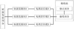
为实现上述目的,本发明采用的技术方案是:一种新体制超视距短波定位系统,包括短波发射部分和接收站;短波发射部分包含至少三个短波发射站,用于发射具有相互正交特性的短波信号,通过电离层传播;接收站包括接收部分与修正部分;接收部分采用多通道接收机与阵列天线,用于对天波信号进行DOA估计,并结合已知的短波发射站地理坐标实现自定位;修正部分用于依据电离层模型对DOA估计结果进行修正。In order to achieve the above-mentioned purpose, the technical solution adopted by the present invention is: a new system beyond visual range short-wave positioning system, including a short-wave transmitting part and a receiving station; the short-wave transmitting part includes at least three short-wave transmitting stations, used for transmitting The characteristic short-wave signal propagates through the ionosphere; the receiving station includes a receiving part and a correction part; the receiving part uses a multi-channel receiver and an array antenna to estimate the DOA of the sky-wave signal, and realize it in combination with the known geographical coordinates of the short-wave transmitting station Self-positioning; the correction part is used to correct the DOA estimation result according to the ionospheric model.
在上述的新体制超视距短波定位系统中,短波发射部分采用三角形、Y形或星形进行长基线布站,形成高频斜向发射台链;用于发射具有相互正交特性的调制信号。In the above-mentioned new system over-the-horizon short-wave positioning system, the short-wave transmitting part adopts triangle, Y-shape or star-shaped long-base station layout to form a chain of high-frequency oblique transmitters; it is used to transmit modulated signals with mutual orthogonal characteristics .
在上述的新体制超视距短波定位系统中,短波发射部分采用宽带发射系统,用于根据电离层变化规律,发射对应频段的短波信号,实现300-3000公里的距离覆盖,其工作频段采用5-30MHz。In the above-mentioned new system over-the-horizon short-wave positioning system, the short-wave transmission part adopts a broadband transmission system, which is used to transmit short-wave signals in the corresponding frequency band according to the ionospheric change rule, to achieve distance coverage of 300-3000 kilometers, and its working frequency band adopts 5 -30MHz.
在上述的新体制超视距短波定位系统中,接收部分采用宽带短基线天线阵列,用于接收短波发射站信号,并依据各发射站编码序列区分信号来源,对按码制进行相关处理后的信号进行到达角估计。In the above-mentioned new system over-the-horizon short-wave positioning system, the receiving part adopts a wide-band short-baseline antenna array to receive signals from short-wave transmitting stations, and distinguishes the source of signals according to the code sequence of each transmitting station, and performs related processing according to the code system. signal for angle of arrival estimation.
一种新体制超视距短波定位方法,根据接收站所测得的各短波发射站信号的来波到达角与已知的短波发射站地理坐标进行交汇式自定位;包括以下步骤:A new system over-the-horizon short-wave positioning method, according to the incoming wave arrival angle of each short-wave transmitting station signal measured by the receiving station and the known geographical coordinates of the short-wave transmitting station to carry out intersection self-positioning; including the following steps:
步骤1、各短波发射站发射具有相互正交特性的短波信号,并通过电离层反射;
步骤2、接收部分接收来波信号,并根据短波发射站的信号模式,采用对应码制解调来波信号,并进行DOA估计;
步骤3、进行接收站的粗定位和精定位;Step 3, carry out coarse positioning and fine positioning of the receiving station;
步骤3.1、通过直接测量所得各发射站的来波到达角与已知的发射站地理坐标,利用大圆定位算法,采用交汇定位的方式对接收站进行粗定位;Step 3.1, by directly measuring the incoming angle of arrival of each transmitting station and the known geographic coordinates of the transmitting station, using the great circle positioning algorithm, and adopting the intersection positioning method to roughly locate the receiving station;
步骤3.2、根据粗定位结果通过优化算法对来波到达角进行校正,利用校正后的来波到达角再次采用交汇定位的方式对接收站进行精定位;获得接收站的经纬度。Step 3.2: Correct the incoming wave arrival angle through the optimization algorithm according to the rough positioning result, and use the corrected incoming wave arrival angle to fine-position the receiving station again by means of intersection positioning; obtain the longitude and latitude of the receiving station.
在上述的新体制超视距短波定位系统的定位方法中,步骤2所述接收部分进行DOA估计采用空间干涉法或者是超分辨率谱估计方法。In the positioning method of the above-mentioned new system over-the-horizon short-wave positioning system, the receiving part in
在上述的新体制超视距短波定位系统的定位方法中,步骤3.1所述大圆定位算法包括:求得接收部分所收到的各短波发射站信号传播射线所在大圆平面的法向量;接收站位于各传播射线所在大圆的交点,通过求得任意两条传播射线所在大圆平面的法向量的公共垂直向量并结合接收站必须在地球表面的条件计算出接收站坐标。In the positioning method of the above-mentioned new system over-the-horizon short-wave positioning system, the great-circle positioning algorithm described in step 3.1 includes: obtaining the normal vector of the great-circle plane where the signals of each short-wave transmitting station received by the receiving part propagate ray; the receiving station is located at For the intersection point of the great circle where each propagating ray is located, the coordinates of the receiving station are calculated by obtaining the common vertical vector of the normal vectors of the great circle plane where any two propagating rays are located and combining the condition that the receiving station must be on the surface of the earth.
在上述的新体制超视距短波定位系统的定位方法中,步骤3.2所述优化算法包括:获得粗定位结果之后,假定该定位点为准确点的前提下,计算出各个发射站相对于该定位点的方位角,将该方位角与由接收站测得方位角进行求差值的绝对值和;以此作为一个衡量定位点与准确点之间误差的判据,在小范围内对到达角进行搜索,并计算新的接收站位置,然后依靠接收站、发射站的位置反过来考察到达角的准确性,寻找匹配的到达角与接收站坐标对对粗定位结果进行修正,实现精确定位。In the positioning method of the above-mentioned new system over-the-horizon short-wave positioning system, the optimization algorithm described in step 3.2 includes: after obtaining the rough positioning result, assuming that the positioning point is an accurate point, calculate the position of each transmitting station relative to the positioning point. The azimuth of the point, the absolute value sum of the difference between the azimuth and the azimuth measured by the receiving station; as a criterion for measuring the error between the positioning point and the exact point, the angle of arrival is calculated in a small range Search and calculate the new location of the receiving station, and then rely on the location of the receiving station and the transmitting station to check the accuracy of the angle of arrival, find the matching angle of arrival and the coordinates of the receiving station to correct the rough positioning results, and achieve precise positioning.
本发明的有益效果:1、本发明结合天波超视距传播机理和测向交汇定位技术,不依赖于卫等复杂昂贵的信号即可实现定位导航,成本低廉。Beneficial effects of the present invention: 1. The present invention combines sky-wave over-the-horizon propagation mechanism and direction-finding intersection positioning technology, and can realize positioning and navigation without relying on complex and expensive signals such as satellites, and the cost is low.
2、采用具有相互正交特性的编码短波信号,不同发射台站即使工作于同频状态也不会相互影响,具有较高的信噪比、抗干扰性与测角精度。2. Using coded short-wave signals with mutually orthogonal characteristics, different transmitting stations will not affect each other even if they work in the same frequency state, and have high signal-to-noise ratio, anti-interference and angle measurement accuracy.
3、其站点布置要求不严格,仅需明确发射站精确地理坐标即可,灵活性大。3. Its site layout requirements are not strict, only the precise geographical coordinates of the transmitting station need to be specified, and the flexibility is large.
4、设备简单,短波发射站与接收站均便于移动,具有极强的机动性。4. The equipment is simple, and the short-wave transmitting station and receiving station are both easy to move and have strong mobility.
5、组网方便,接收站不发射信号,隐蔽性强。5. The networking is convenient, the receiving station does not transmit signals, and the concealment is strong.
6、采用短波超视距定位的方法,远距离的接收终端也可以很方便的接受服务。6. Using the short-wave over-the-horizon positioning method, long-distance receiving terminals can also receive services very conveniently.
7、对发射站数目无上限要求,扩展方便,且发射站数目越多定位准确性越强。7. There is no upper limit requirement for the number of transmitting stations, which is convenient for expansion, and the more the number of transmitting stations, the stronger the positioning accuracy.
实现了不依赖于卫星、VLF等导航信号的短波超视距定位,具有成本低廉、灵活性大、隐蔽与机动性强、扩展性好优点。It realizes short-wave over-the-horizon positioning that does not depend on navigation signals such as satellites and VLFs, and has the advantages of low cost, high flexibility, strong concealment and maneuverability, and good scalability.
附图说明Description of drawings
图1为本发明一个实施例新体制超视距短波定位系统结构示意图;Fig. 1 is a schematic structural diagram of a new system over-the-horizon short-wave positioning system of an embodiment of the present invention;
图2为本发明一个实施例定位方法工作流程图;Fig. 2 is a flow chart of the positioning method of an embodiment of the present invention;
图3为本发明一个实施例陆基远程无线电定位工作示例图;Fig. 3 is an example diagram of land-based remote radio positioning work according to an embodiment of the present invention;
图4为本发明一个实施例大圆算法的信号传播示意图;Fig. 4 is a schematic diagram of signal propagation of a great circle algorithm according to an embodiment of the present invention;
图5为本发明一个实施例大圆算法的局部示意图;Fig. 5 is a partial schematic diagram of a great circle algorithm according to an embodiment of the present invention;
图6为本发明一个实施例射线大圆相交示意图;Fig. 6 is a schematic diagram of ray great circle intersection in an embodiment of the present invention;
图7为本发明一个实施例局部搜索定位示意图;Fig. 7 is a schematic diagram of local search and positioning according to an embodiment of the present invention;
图8为本发明一个实施例互补码自相关特性图;Fig. 8 is an autocorrelation characteristic diagram of a complementary code according to an embodiment of the present invention;
图9为本发明一个实施例完互补码互相关特性示意图Fig. 9 is a schematic diagram of cross-correlation characteristics of complementary codes according to an embodiment of the present invention
图10为本发明一个实施例有源测向方式信号频谱图;Fig. 10 is a signal spectrum diagram of an active direction finding mode according to an embodiment of the present invention;
图11为本发明一个实施例无源接收方式信号频谱图。Fig. 11 is a spectrum diagram of a signal in a passive receiving mode according to an embodiment of the present invention.
具体实施方式detailed description
下面结合附图对本发明的实施方式进行详细描述。Embodiments of the present invention will be described in detail below in conjunction with the accompanying drawings.
本实施例提供一种能够实现不依赖于卫星、VLF等导航信号的短波超视距定位,具有成本低廉、灵活性大、隐蔽与机动性强、扩展性好优点的新体制短波超视距定位系统及定位方法。This embodiment provides a new short-wave over-the-horizon positioning system that can realize short-wave over-the-horizon positioning that does not depend on navigation signals such as satellites and VLFs, and has the advantages of low cost, high flexibility, strong concealment and maneuverability, and good scalability. system and positioning method.
本实施例通过以下技术方案来实现,一种新体制超视距短波定位系统,包括短波发射分部分、接收部分、修正部分。短波发射部分依靠电离层反射实现短波信号的大范围覆盖。修正部分与接收部分在接收站实现。接收部分采用多通道接收机与阵列天线对天波信号进行DOA估计,并结合已知的发射站地理坐标实现自定位。修正部分则根据电离层模型对DOA估计结果进行修正,提高定位精度。This embodiment is realized through the following technical solutions, a new system over-the-horizon short-wave positioning system, including a short-wave transmitting subsection, a receiving section, and a correction section. The short-wave transmission part relies on ionospheric reflection to achieve wide-area coverage of short-wave signals. The correction part and the receiving part are implemented in the receiving station. The receiving part uses a multi-channel receiver and an array antenna to estimate the DOA of the sky-wave signal, and combines the known geographical coordinates of the transmitting station to realize self-positioning. The correction part corrects the DOA estimation result according to the ionospheric model to improve the positioning accuracy.
而且,短波发射部分需至少包含三个短波发射站,进行长基线布站(例如三角形、Y形或星形),拥有精确的地理坐标,组成高频斜向发射台链,发射具有相互正交特性的编码短波信号。Moreover, the short-wave transmitting part needs to include at least three short-wave transmitting stations for long-baseline layout (such as triangle, Y-shape or star), with precise geographical coordinates, to form a chain of high-frequency oblique transmitting stations, and to transmit with mutual orthogonality. Characteristics of coded shortwave signals.
并且,短波发射部分采用宽带的发射系统。为了根据电离层变化规律,发射合适频段的短波信号,实现300-3000公里的距离覆盖,工作频段采用5-30MHz。其电波发射频率选择依据多样,即可依靠全球的固定电离层模型选择,也可根据传播路径上的电离层探测台站的实时分析结果进行选频。Moreover, the short-wave transmission part adopts a broadband transmission system. In order to transmit short-wave signals in the appropriate frequency band according to the changing law of the ionosphere to achieve a distance coverage of 300-3000 kilometers, the working frequency band is 5-30MHz. Its radio wave emission frequency is selected based on various basis, which can be selected by relying on the global fixed ionospheric model, or can be selected according to the real-time analysis results of the ionospheric detection stations on the propagation path.
而且,接收部分利用短基线宽带接收天线阵列接收所有短波发射台站信号,并依据各发射站编码序列的不同区分信号来源,然后对按码制进行相关处理后的信号进行到达角估计,以提高信噪比、抗干扰性与测角精度。Moreover, the receiving part uses the short-baseline broadband receiving antenna array to receive all the short-wave transmitting station signals, and distinguishes the source of the signal according to the code sequence of each transmitting station, and then estimates the angle of arrival of the signal after the correlation processing according to the code system, so as to improve Signal-to-noise ratio, anti-interference and angle measurement accuracy.
一种新体制超视距短波定位的方法,包括短波发射分部分、接收部分、修正部分。其中短波发射部分依靠三台或三台以上的短波发射站,多个短波发射站进行长基线布置,发射具有相互正交特性的短波信号,经电离层反射传播到远方。而接收部分利用阵列天线接收各短波发射站的短波信号,依靠已知的编码方式区分多个信号来源,通过测量多个天波信号到达角的方位角信息,并结合已知的短波发射站地理坐标实现接收站的自定位。修正部分根据粗定位结果进行小范围局部优化搜索修正定位结果。A short-wave positioning method beyond visual distance in a new system, including a short-wave transmitting part, a receiving part, and a correcting part. Among them, the short-wave transmitting part relies on three or more short-wave transmitting stations. Multiple short-wave transmitting stations are arranged with long baselines to transmit short-wave signals with mutual orthogonal characteristics, which are reflected and propagated to distant places through the ionosphere. The receiving part uses the array antenna to receive the short-wave signals of each short-wave transmitting station, relies on known coding methods to distinguish multiple signal sources, and measures the azimuth angle information of the arrival angle of multiple sky-wave signals, combined with the known geographic coordinates of the short-wave transmitting stations Realize the self-positioning of the receiving station. The correction part performs a small-scale local optimization search and corrects the positioning results according to the rough positioning results.
根据接收站所测得的各短波发射站信号的来波到达角与已知的短波发射站地理经纬度坐标进行交汇式自定位。接收站的自定位过程分为粗定位与精定位两步进行。According to the incoming wave arrival angle of each short-wave transmitting station signal measured by the receiving station and the known geographical longitude and latitude coordinates of the short-wave transmitting station, the intersection self-positioning is performed. The self-positioning process of the receiving station is divided into two steps: rough positioning and fine positioning.
粗定位采用接收站测量的来波到达角进行定位,获得大致位置;精定位在粗定位之后进行,接收站的自定位过程分为粗定位与精定位两步进行计算,粗定位计算采用大圆定位算法,精定位计算采用优化算法。Coarse positioning uses the incoming wave arrival angle measured by the receiving station to perform positioning to obtain an approximate position; fine positioning is performed after rough positioning, and the self-positioning process of the receiving station is divided into two steps: coarse positioning and fine positioning. The rough positioning calculation uses great circle positioning Algorithm, fine positioning calculation adopts optimization algorithm.
大圆定位算法的原理为:首先求得接收站所收到的各短波发射站信号传播射线所在大圆平面的法向量;接收站位置应在各传播射线所在大圆的交点上,因此可通过求得任意两条传播射线所在大圆平面的法向量的公共垂直向量并结合接收站必须在地球表面的条件计算出接收站坐标。The principle of the great circle positioning algorithm is as follows: firstly, obtain the normal vector of the great circle plane where the propagation rays of the shortwave transmitting station signals received by the receiving station are obtained; The coordinates of the receiving station are calculated from the common vertical vector of the normal vectors of the great circle plane where the two propagating rays are located and in combination with the condition that the receiving station must be on the earth's surface.
精确定位在粗定位之后进行,依据粗定位的结果与已知的短波发射站地理坐标,在小范围内对到达角进行搜索,并计算新的接收站位置,然后依靠接收发射站的位置反过来考察到达角的准确性,寻找匹配的到达角与接收站坐标对,作为本方法的修正部分对来波到达角进行修正,实现精定位。Accurate positioning is carried out after rough positioning. Based on the results of rough positioning and the known geographical coordinates of the short-wave transmitting station, the angle of arrival is searched in a small area, and the new receiving station position is calculated, and then the position of the receiving and transmitting station is reversed. Investigate the accuracy of the angle of arrival, find the matching angle of arrival and the coordinate pair of the receiving station, as the correction part of this method, correct the angle of arrival of incoming waves to achieve precise positioning.
接收站交汇定位的结果仅依赖于已知的发射站地理坐标与接收站DOA估计的方位角信息,较低精度的仰角测量结果不会对定位结果造成影响。The result of intersection positioning of the receiving station only depends on the known geographic coordinates of the transmitting station and the azimuth information estimated by the DOA of the receiving station, and the lower-precision elevation angle measurement results will not affect the positioning results.
具体实施时,如图1所示,一种新体制短波超视距定位系统,包括短波发射部分、接收部分、修正部分。短波发射台发射具有相互正交特性的短波信号,并通过电离层传播实现大范围覆盖。修正部分与接收部分共同组成接收站。接收站通过对天波信号根据已知的编码序列进行相关处理,确定信号来源并进行DOA估计,再结合已知的各短波发射站地理坐标以交汇定位的方式实现自定位。修正方法则以一种局部搜索最优化的方式对粗定位结果进行修正,提高定位精度。When implementing it, as shown in Figure 1, a new short-wave over-the-horizon positioning system includes a short-wave transmitting part, a receiving part, and a correcting part. The short-wave transmitting station transmits short-wave signals with mutually orthogonal characteristics, and achieves large-scale coverage through ionospheric propagation. The correction part and the receiving part together form a receiving station. The receiving station performs correlation processing on the sky-wave signal according to the known code sequence, determines the source of the signal and performs DOA estimation, and then combines the known geographical coordinates of each short-wave transmitting station to achieve self-positioning in the way of intersection positioning. The correction method uses a local search optimization method to correct the rough positioning results and improve the positioning accuracy.
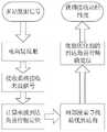
如图2所示,一种新体制短波超视距定位方法的工作流程为:首先短波信号采用具有相互正交特性的编码方式由分布于多地的短波发射站发射,经电离层的反射作用,短波信号被远方的接收部分所接收;接收部分通过接收天线阵所获得的多通道信号进行DOA估计,并依靠公开已知的发射站地理坐标采用交汇定位的方式对接收站本身进行粗略的大致定位;然后根据粗定位结果依据电离层模型对已测得的各短波发射站来波到达角进行修正;最后再使用修正过的来波到达角,根据短波发射站地理坐标对接收站自身进行精定位并输出接收站自身的经纬度。As shown in Figure 2, the working process of a new short-wave over-the-horizon positioning method is as follows: first, short-wave signals are transmitted by short-wave transmitting stations distributed in many places in a coded manner with mutual orthogonal characteristics, and reflected by the ionosphere , the shortwave signal is received by the remote receiving part; the receiving part performs DOA estimation through the multi-channel signal obtained by the receiving antenna array, and relies on the publicly known geographical coordinates of the transmitting station to make a rough rough estimate of the receiving station itself Positioning; then according to the rough positioning results and the ionospheric model, the measured arrival angles of the short-wave transmitting stations are corrected; finally, the corrected incoming wave arrival angles are used to fine-tune the receiving station itself according to the geographical coordinates of the short-wave transmitting stations. Locate and output the longitude and latitude of the receiving station itself.
短波发射部分由至少三个短波发射站组成,进行长基线布站(例如三角形、Y形或星形),各短波发射站拥有精确的地理坐标,并为所有接收站所知,组成高频斜向发射台链。The short-wave transmitting part is composed of at least three short-wave transmitting stations, and the long-baseline layout (such as triangle, Y or star) is carried out. Each short-wave transmitting station has precise geographic coordinates and is known to all receiving stations to form a high-frequency oblique chain to the launch pad.
短波发射部分为宽带系统,按电离层变化规律,发射合适频段的高频电磁波,实现300-3000公里的距离覆盖,工作频段为5-30MHz。The short-wave transmitting part is a broadband system. According to the changing law of the ionosphere, it transmits high-frequency electromagnetic waves in a suitable frequency band to achieve a distance coverage of 300-3000 kilometers, and the working frequency band is 5-30MHz.
为区别各短波发射台站的信号,各短波发射站的短波信号可以采用具有正交特性的调制信号,使接收站可以实现来波到达角与发射站地理坐标的配对。In order to distinguish the signals of each short-wave transmitting station, the short-wave signal of each short-wave transmitting station can adopt a modulation signal with orthogonal characteristics, so that the receiving station can realize the pairing of the incoming wave arrival angle and the geographical coordinates of the transmitting station.
相对应的,接收站的接收部分采用宽带短基线的天线阵列,根据短波发射站的信号模式,在接收部分依次采用对应码制解调到达信号,并进行DOA估计。Correspondingly, the receiving part of the receiving station uses a broadband short-baseline antenna array. According to the signal mode of the short-wave transmitting station, the receiving part sequentially uses the corresponding code system to demodulate the arriving signal and perform DOA estimation.
接收部分对于来波信号的DOA估计采用空间干涉法或者是超分辨率谱估计方法,特别是对于采用对应码序列相关处理后的信号来说,测向所用信号序列具有较高的信噪比与抗干扰性,具有较好的估计精度。The receiving part adopts spatial interferometry or super-resolution spectrum estimation method for the DOA estimation of the incoming wave signal, especially for the signal after correlation processing with the corresponding code sequence, the signal sequence used for direction finding has a higher signal-to-noise ratio and Anti-interference, with better estimation accuracy.
接收站的自定位过程分为粗定位与精确定位两步进行:The self-positioning process of the receiving station is divided into two steps: rough positioning and precise positioning:
A.首先依靠直接测量的来自各短波发射站的天波信号到达角与已知的短波发射站地理坐标,利用创新的大圆算法,采用交汇定位的方式计算接收站的大致位置。其大圆算法流程为:首先求得接收站所收到的各短波发射站信号传播射线所在大圆平面的法向量;接收站位置应在各传播射线所在大圆的交点上,因此可通过求得任意两条传播射线所在大圆平面的法向量的公共垂直向量并结合接收站必须在地球表面的条件计算出接收站坐标。A. First rely on the direct measurement of the angle of arrival of sky-wave signals from each short-wave transmitting station and the known geographical coordinates of the short-wave transmitting station, and use the innovative great circle algorithm to calculate the approximate position of the receiving station by means of intersection positioning. The great circle algorithm process is as follows: Firstly, obtain the normal vector of the great circle plane where the signal propagation rays of the short-wave transmitting stations received by the receiving station are located; The coordinates of the receiving station are calculated by combining the common vertical vector of the normal vector of the great circle plane where the propagation rays are located and combining the condition that the receiving station must be on the earth's surface.
B.然后根据粗定位结果通过优化算法对来波到达角进行适当校正,利用校正后的来波到达角再次采用交汇定位的方法实现对接收站的精定位。其中优化算法的方法为:获得定位点粗略结果之后,在假定该定位点为准确点的前提下,可以计算出各个发射站相对于该定位点的方位角,此时,就可以将该方位角与原来由接收站测得方位角进行求差值的绝对值和,并以此作为一个衡量定位点与准确点之间误差的判据,在小范围内对到达角进行搜索,并计算新的接收站位置,然后依靠接收发射站的位置反过来考察到达角的准确性,寻找匹配的到达角与接收站坐标对对粗定位结果进行修正,实现精确定位。B. Then, according to the rough positioning results, the angle of arrival of the incoming wave is properly corrected through the optimization algorithm, and the fine positioning of the receiving station is realized by using the method of intersection positioning again by using the corrected angle of arrival of the incoming wave. The method of optimizing the algorithm is: after obtaining the rough result of the positioning point, assuming that the positioning point is an accurate point, the azimuth angle of each transmitting station relative to the positioning point can be calculated. At this time, the azimuth angle can be Calculate the absolute value of the difference with the azimuth angle originally measured by the receiving station, and use this as a criterion to measure the error between the positioning point and the exact point, search for the angle of arrival in a small range, and calculate the new The position of the receiving station, and then rely on the position of the receiving and transmitting station to examine the accuracy of the angle of arrival in turn, and find the matching angle of arrival and coordinates of the receiving station to correct the rough positioning results and achieve precise positioning.
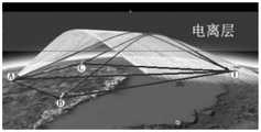
图3所示为本实施例陆基远程无线电定位工作示例图,三台(或多台)短波发射站(图中A,B,C所示)分别设于不同的位置,其地理经纬度坐标已知即可。根据电离层变化规律,采用一组相互正交的完全互补码,发射合适频段的短波信号,其电波覆盖距离可达300-3000公里。接收站(图中T所示)位于信号覆盖区域,同步接收来自三个短波发射站的高频信号,并精确测量每个波的到达角。Fig. 3 is shown as the example diagram of land-based remote radio positioning work of the present embodiment, three (or more) short-wave transmitting stations (shown in A, B, C in the figure) are arranged in different positions respectively, and its geographic latitude and longitude coordinates have been Just know. According to the changing law of the ionosphere, a set of mutually orthogonal complete complementary codes is used to transmit short-wave signals in suitable frequency bands, and the radio wave coverage distance can reach 300-3000 kilometers. The receiving station (shown as T in the figure) is located in the signal coverage area, synchronously receives the high-frequency signals from the three shortwave transmitting stations, and accurately measures the angle of arrival of each wave.
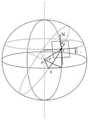
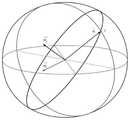
如图4所示为一个信号的球面传播模型,可作为大圆算法的信号传播示意图;设已知点A经度为θ,纬度为


其中面OAC⊥面OBC,做B点处切平面BDE,DE为该面与面OAC交线;再做A点处切平面AFG,FG为该面与面OBC交线。其中OA、OB和OC为地球半径r。β和分别为γ,∠COB与∠EBD。由几何关系做如下推导:Among them, surface OAC⊥surface OBC, make the tangent plane BDE at point B, DE is the intersection line between this surface and surface OAC; then make the tangent plane AFG at point A, and FG is the intersection line between this surface and surface OBC. Where OA, OB and OC are the radius r of the earth. β and γ, ∠COB and ∠EBD respectively. From the geometric relationship, the following derivation is made:


BD=r·tanβBD=r·tanβ

然后可有求得的β和γ来表示出大圆面法向量。设大圆面法向量


对于任意两个发射站,求得两射线所在的两大圆面交线与球面的两交点,也就是两条射线可能在地球表面上相交的点坐标即为接收站位置。如图6所示第一短波发射站和第二短波发射站射线路径分别对应两个大圆。两大圆路径的交点,即定位点向量,由于同时在两大圆面上,满足与两法向量垂直关系。由此问题演变为求两个法向量的公共垂直向量。设已知向量


其中r为地球半径,方程组有两组解,按照实际应用情况,选取距离两发射站较近的解作为定位点,获得粗定位结果。Where r is the radius of the earth, and the equations have two sets of solutions. According to the actual application situation, the solution closer to the two transmitting stations is selected as the positioning point to obtain the rough positioning result.
然后根据粗定位定位结果与到达角按前面所述的方法进行修正,图7直观的展示了这一方法。Then, according to the rough positioning positioning results and the angle of arrival, corrections are made according to the method described above. Figure 7 shows this method intuitively.
如图8与图9所示,当采用具有相互正交特性的编码信号时(在此例中采用完全互补码序列),各发射站具有较好的自相关特性,这便于脉冲压缩与信号的增强,而相互之间良好的互相关特性也有力地保证了多个发射站之间的信号隔离,更便利于信号来源的区分与信道间的抗干扰性。As shown in Figure 8 and Figure 9, when using coded signals with mutual orthogonal characteristics (in this case, using a complete complementary code sequence), each transmitting station has better autocorrelation characteristics, which is convenient for pulse compression and signal Enhanced, and the good cross-correlation characteristics between them also effectively guarantee the signal isolation between multiple transmitting stations, which is more convenient for the distinction of signal sources and the anti-interference between channels.
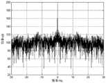
如图10所示,为采用有源测向的方式信号频谱图,相较于如图11所示的采用无源接收方式信号频谱图可以获得更好的信杂比,对于杂波信号有很好的抗干扰性,更有利于提高测向精度。As shown in Figure 10, it is the signal spectrum diagram of the active direction finding method. Compared with the signal spectrum diagram of the passive reception method shown in Figure 11, a better signal-to-clutter ratio can be obtained, and it is very good for clutter signals. Good anti-interference is more conducive to improving the accuracy of direction finding.
应当理解的是,本说明书未详细阐述的部分均属于现有技术。It should be understood that the parts not described in detail in this specification belong to the prior art.
虽然以上结合附图描述了本发明的具体实施方式,但是本领域普通技术人员应当理解,这些仅是举例说明,可以对这些实施方式做出多种变形或修改,而不背离本发明的原理和实质。本发明的范围仅由所附权利要求书限定。Although the specific embodiments of the present invention have been described above in conjunction with the accompanying drawings, those of ordinary skill in the art should understand that these are only examples, and various variations or modifications can be made to these embodiments without departing from the principles and principles of the present invention. substance. The scope of the invention is limited only by the appended claims.
Claims (1)
Priority Applications (1)
| Application Number | Priority Date | Filing Date | Title |
|---|---|---|---|
| CN201910146132.8ACN109856597B (en) | 2019-02-27 | 2019-02-27 | New system over-the-horizon short wave positioning system and positioning method |
Applications Claiming Priority (1)
| Application Number | Priority Date | Filing Date | Title |
|---|---|---|---|
| CN201910146132.8ACN109856597B (en) | 2019-02-27 | 2019-02-27 | New system over-the-horizon short wave positioning system and positioning method |
Publications (2)
| Publication Number | Publication Date |
|---|---|
| CN109856597A CN109856597A (en) | 2019-06-07 |
| CN109856597Btrue CN109856597B (en) | 2022-12-16 |
Family
ID=66899125
Family Applications (1)
| Application Number | Title | Priority Date | Filing Date |
|---|---|---|---|
| CN201910146132.8AExpired - Fee RelatedCN109856597B (en) | 2019-02-27 | 2019-02-27 | New system over-the-horizon short wave positioning system and positioning method |
Country Status (1)
| Country | Link |
|---|---|
| CN (1) | CN109856597B (en) |
Families Citing this family (2)
| Publication number | Priority date | Publication date | Assignee | Title |
|---|---|---|---|---|
| CN111007490B (en)* | 2019-12-05 | 2022-03-15 | 武汉大学 | Sky wave over-the-horizon radar coordinate registration method based on buoy geographic information |
| CN119959859B (en)* | 2025-01-15 | 2025-09-30 | 武汉大学 | Method and system for direction finding of foundation multichannel very low frequency signal |
Citations (7)
| Publication number | Priority date | Publication date | Assignee | Title |
|---|---|---|---|---|
| EP2428810A1 (en)* | 2010-09-08 | 2012-03-14 | Thales | Multi-transmitter geo-positioning method by space-time processing. |
| CN103698743A (en)* | 2013-12-13 | 2014-04-02 | 国家无线电监测中心 | Ionospheric-reflection-based time difference of arrival positioning method for shortwave radiation source |
| CN103698753A (en)* | 2013-12-19 | 2014-04-02 | 武汉大学 | Passive passage correcting method of small-size array |
| CN103869293A (en)* | 2014-03-31 | 2014-06-18 | 武汉大学 | Method for simultaneously receiving sky wave and ground wave BVR radar signals |
| CN106291540A (en)* | 2016-09-14 | 2017-01-04 | 河北省电力勘测设计研究院 | A kind of multiple-input and multiple-output GPR backwards projection target imaging method estimated based on DOA |
| CN108089147A (en)* | 2017-12-07 | 2018-05-29 | 西南电子技术研究所(中国电子科技集团公司第十研究所) | Improved shortwave unit localization method |
| CN109031197A (en)* | 2018-06-19 | 2018-12-18 | 哈尔滨工业大学 | A kind of direct localization method of radiation source based on over-the-horizon propagation model |
- 2019
- 2019-02-27CNCN201910146132.8Apatent/CN109856597B/ennot_activeExpired - Fee Related
Patent Citations (7)
| Publication number | Priority date | Publication date | Assignee | Title |
|---|---|---|---|---|
| EP2428810A1 (en)* | 2010-09-08 | 2012-03-14 | Thales | Multi-transmitter geo-positioning method by space-time processing. |
| CN103698743A (en)* | 2013-12-13 | 2014-04-02 | 国家无线电监测中心 | Ionospheric-reflection-based time difference of arrival positioning method for shortwave radiation source |
| CN103698753A (en)* | 2013-12-19 | 2014-04-02 | 武汉大学 | Passive passage correcting method of small-size array |
| CN103869293A (en)* | 2014-03-31 | 2014-06-18 | 武汉大学 | Method for simultaneously receiving sky wave and ground wave BVR radar signals |
| CN106291540A (en)* | 2016-09-14 | 2017-01-04 | 河北省电力勘测设计研究院 | A kind of multiple-input and multiple-output GPR backwards projection target imaging method estimated based on DOA |
| CN108089147A (en)* | 2017-12-07 | 2018-05-29 | 西南电子技术研究所(中国电子科技集团公司第十研究所) | Improved shortwave unit localization method |
| CN109031197A (en)* | 2018-06-19 | 2018-12-18 | 哈尔滨工业大学 | A kind of direct localization method of radiation source based on over-the-horizon propagation model |
Non-Patent Citations (2)
| Title |
|---|
| 多基高频天波超视距定位模型;宋君等;《系统工程与电子技术》;20110215(第02期);第273-275页* |
| 短波单站定位技术研究与应用;朱鹏;《中国博士学位论文全文数据库信息科技辑》;20170815(第8期);正文第36-104页* |
Also Published As
| Publication number | Publication date |
|---|---|
| CN109856597A (en) | 2019-06-07 |
Similar Documents
| Publication | Publication Date | Title |
|---|---|---|
| CN102981144B (en) | Method for three-dimensional passive positioning of targets by air moving platform | |
| TWI438465B (en) | Method system and mobile unit for locating a geogprahical position using broadcast frequency modulation signals | |
| US8200244B2 (en) | Method and system for mobile station location | |
| Kloeden et al. | Vehicle localization using cooperative RF-based landmarks | |
| US20020196186A1 (en) | Method and system for calibrating wireless location systems | |
| CN109557562B (en) | GNSS interference source positioning method based on radio wave propagation model | |
| US20050073459A1 (en) | Method and system for time difference of arrival (TDOA) location services | |
| CN103576138B (en) | A Spaceborne Passive Radar Positioning Method Based on GNSS-R Signal Geometric Relationship | |
| CN204166130U (en) | Radio frequency locating device and system | |
| KR20120107128A (en) | Indoor positioning system based on gps signals and pseudolites with outdoor directional antennas | |
| CN108693545A (en) | Abnormal target positioning method based on satellite-borne ADS-B | |
| US7403155B2 (en) | Method for the accelerated acquisition of satellite signals | |
| US7272495B2 (en) | System and method for inverse multilateration | |
| CN103097906A (en) | Method and apparatus for determining the position and orientation of a mobile transmitter | |
| RU2275649C2 (en) | Method and passive radar for determination of location of radio-frequency radiation sources | |
| WO2019001415A1 (en) | Large-area and high-precision positioning method capable of replacing conventional radio navigation system | |
| CN102300311A (en) | Positioning method for revising ground mobile communication network by using map elevation | |
| CN113347572A (en) | Method and system for realizing terminal positioning by using aerial base station | |
| CN109856597B (en) | New system over-the-horizon short wave positioning system and positioning method | |
| CN105487094A (en) | Data link and satellite navigation collaborative positioning method and positioning system | |
| JP2020159705A (en) | Position estimation device and position estimation method | |
| CN109490828B (en) | Localization method based on homologous baseline array | |
| US20040085242A1 (en) | Synthetic Doppler system and method for locating cooperative transceivers | |
| Yang et al. | A novel land-based high-frequency geolocation system | |
| US3553691A (en) | Long range position determination system |
Legal Events
| Date | Code | Title | Description |
|---|---|---|---|
| PB01 | Publication | ||
| PB01 | Publication | ||
| SE01 | Entry into force of request for substantive examination | ||
| SE01 | Entry into force of request for substantive examination | ||
| GR01 | Patent grant | ||
| GR01 | Patent grant | ||
| CF01 | Termination of patent right due to non-payment of annual fee | ||
| CF01 | Termination of patent right due to non-payment of annual fee | Granted publication date:20221216 |