CN109847315B - Badminton sports training equipment - Google Patents
Badminton sports training equipmentDownload PDFInfo
- Publication number
- CN109847315B CN109847315BCN201910059305.2ACN201910059305ACN109847315BCN 109847315 BCN109847315 BCN 109847315BCN 201910059305 ACN201910059305 ACN 201910059305ACN 109847315 BCN109847315 BCN 109847315B
- Authority
- CN
- China
- Prior art keywords
- fixedly connected
- electric push
- long
- badminton
- push rod
- Prior art date
- Legal status (The legal status is an assumption and is not a legal conclusion. Google has not performed a legal analysis and makes no representation as to the accuracy of the status listed.)
- Expired - Fee Related
Links
- XEEYBQQBJWHFJM-UHFFFAOYSA-NIronChemical compound[Fe]XEEYBQQBJWHFJM-UHFFFAOYSA-N0.000claimsdescription6
- 239000000463materialSubstances0.000claimsdescription5
- 229910052742ironInorganic materials0.000claimsdescription3
- 235000017166Bambusa arundinaceaNutrition0.000claims2
- 235000017491Bambusa tuldaNutrition0.000claims2
- 241001330002BambuseaeSpecies0.000claims2
- 235000015334Phyllostachys viridisNutrition0.000claims2
- 239000011425bambooSubstances0.000claims2
- 238000009434installationMethods0.000claims1
- 238000012544monitoring processMethods0.000claims1
- 230000000149penetrating effectEffects0.000claims1
- 238000010304firingMethods0.000abstractdescription4
- 230000000694effectsEffects0.000abstractdescription3
- 230000002093peripheral effectEffects0.000abstractdescription3
- 238000000034methodMethods0.000description5
- 230000009286beneficial effectEffects0.000description3
- 210000003746featherAnatomy0.000description3
- 238000010586diagramMethods0.000description2
- 230000036651moodEffects0.000description2
- 230000008602contractionEffects0.000description1
- 230000007547defectEffects0.000description1
- 238000005516engineering processMethods0.000description1
- 238000012986modificationMethods0.000description1
- 230000004048modificationEffects0.000description1
- 230000000737periodic effectEffects0.000description1
- 230000035900sweatingEffects0.000description1
Images


Landscapes
- Rehabilitation Tools (AREA)
- Toys (AREA)
Abstract
Translated fromChinese
Description
Translated fromChinese技术领域technical field
本发明属于体育设备技术领域,具体地说是一种羽毛球体育训练器材。The invention belongs to the technical field of sports equipment, in particular to a badminton sports training equipment.
背景技术Background technique
羽毛球运动适合于男女老幼,运动量可根据个人年龄、体质、运动水平和场地环境的特点而定。在进行正规的羽毛球训练时,较为原始的方式是由陪练者向练习者方向击球,目前也有用于羽毛球的发球装置,但现有技术中的发球装置要么过于复杂昂贵,要么无法无法适应全场地灵活发球的要求,且目前此类装置中大多为单次发球,再由人们装填羽毛球,不利于练习者进行连续性的击球训练。Badminton is suitable for men and women of all ages, and the amount of exercise can be determined according to individual age, physique, exercise level and the characteristics of the venue environment. In formal badminton training, the more primitive way is to hit the ball in the direction of the practitioner by the sparring player. At present, there are also serving devices for badminton, but the serving devices in the existing technology are either too complicated and expensive, or they cannot adapt to the whole world. The requirements for flexible serving on the field, and most of the current devices are single serving, and then people fill the badminton, which is not conducive to the continuous hitting training of the practitioners.
发明内容SUMMARY OF THE INVENTION
本发明提供一种羽毛球体育训练器材,用以解决现有技术中的缺陷。The present invention provides a badminton sports training equipment for solving the defects in the prior art.
本发明通过以下技术方案予以实现:The present invention is achieved through the following technical solutions:
一种羽毛球体育训练器材,包括长筒,长筒的两端开口,长筒的顶部一侧开设条形槽,条形槽分别同时与长筒内部、外界相通,长筒的顶部另一侧开设第一弧形槽,第一弧形槽与长筒内部相通,长筒的底部一侧固定安装短筒,短筒的一端开口,短筒与长筒的中心线相互平行,短筒的外周顶部开设第二弧形槽,第二弧形槽与短筒内部相通,短筒的内端固定连接数个第一电推杆的一端,短筒内设有锥形管,锥形管与第一电推杆的活动端固定连接,锥形管的内端固定连接折叠管的一端,折叠管的另一端固定连接储气罐的一端,折叠管的另一端内固定安装电动阀门,储气罐从短筒内穿过,长筒的底部固定安装气泵,气泵的出气口与储气罐的另一端固定连接,长筒的顶部固定连接竖板的底面,竖板的一侧固定连接第二电推杆的一端,第二电推杆的另一端固定连接第三电推杆的外周上部,第三电推杆的活动端朝下且固定连接盖板的顶部,盖板的内壁固定安装夹持装置,长筒的顶部固定安装顶料构件,长筒的底部另一侧固定安装矩形块,矩形块的前面开设通透的圆形槽,圆形槽的内壁内侧固定安装触点开关,触点开关与电动阀门电路连接,圆形槽的顶面内侧通过扭簧安装扳机,矩形块的底面固定安装把手,把手与矩形块为一体结构。A badminton sports training equipment, comprising a long barrel, two ends of the long barrel are open, a strip groove is formed on one side of the top of the long barrel, the strip groove is communicated with the inside and the outside of the long barrel respectively, and the other side of the top of the long barrel is opened The first arc-shaped groove, the first arc-shaped groove communicates with the inside of the long barrel, the short barrel is fixedly installed on one side of the bottom of the long barrel, one end of the short barrel is open, the center lines of the short barrel and the long barrel are parallel to each other, and the outer peripheral top of the short barrel is A second arc-shaped groove is opened, the second arc-shaped groove communicates with the interior of the short cylinder, the inner end of the short cylinder is fixedly connected to one end of several first electric push rods, and a conical tube is arranged in the short cylinder, and the conical tube is connected with the first electric push rod. The movable end of the electric push rod is fixedly connected, the inner end of the tapered tube is fixedly connected to one end of the folding tube, the other end of the folding tube is fixedly connected to one end of the gas storage tank, and the other end of the folding tube is fixedly installed with an electric valve, and the gas storage tank is fixed from the Pass through the short tube, the bottom of the long tube is fixedly installed with an air pump, the air outlet of the air pump is fixedly connected to the other end of the air storage tank, the top of the long tube is fixedly connected to the bottom surface of the vertical plate, and one side of the vertical plate is fixedly connected to the second electric pusher One end of the rod, the other end of the second electric push rod is fixedly connected to the upper part of the outer circumference of the third electric push rod, the movable end of the third electric push rod is facing down and is fixedly connected to the top of the cover plate, and the inner wall of the cover plate is fixedly installed with a clamping device , the top of the long cylinder is fixedly installed with the top material member, the other side of the bottom of the long cylinder is fixedly installed with a rectangular block, the front of the rectangular block is provided with a transparent circular groove, and the inner wall of the circular groove is fixedly installed with a contact switch. It is connected with the electric valve circuit, the trigger is installed on the inner side of the top surface of the circular groove through the torsion spring, the bottom surface of the rectangular block is fixedly installed with the handle, and the handle and the rectangular block are integrated.
如上所述的一种羽毛球体育训练器材,所述的夹持装置为两个套筒,套筒分别固定安装在盖板的内壁,且两个套筒的中心线共线,套筒内分别设有活动杆,活动杆均为铁质材料,套筒内分别固定安装电磁线圈,活动杆分别从电磁线圈内穿过,活动杆的外端分别固定安装夹板,夹板均为弧形结构,且夹板的弧面相对,套筒的内端分别固定连接弹簧的一端,弹簧的另一端均与对应的夹板固定连接,活动杆分别从对应的弹簧内穿过。A kind of badminton sports training equipment as mentioned above, the described clamping device is two sleeves, the sleeves are respectively fixed and installed on the inner wall of the cover plate, and the center lines of the two sleeves are collinear, and the sleeves are respectively set. There are movable rods, all of which are made of iron material. Electromagnetic coils are fixed and installed in the sleeves respectively. The movable rods pass through the electromagnetic coils respectively. The outer ends of the movable rods are respectively fixed and installed with splints. The splints are arc-shaped structures, and the splints The arc surfaces of the sleeves are opposite to each other, the inner ends of the sleeves are respectively fixed and connected to one end of the springs, the other ends of the springs are fixedly connected to the corresponding splints, and the movable rods respectively pass through the corresponding springs.
如上所述的一种羽毛球体育训练器材,所述的顶料构件包括数个链轮,链轮之间通过链板连接,长筒内设有与之中心线共线的圆板,圆板的内侧固定连接顶杆的一端,顶杆的另一端与最外侧的羽毛球的球托接触,圆板的顶部固定连接竖杆的下端,竖杆从条形槽内穿过,竖杆的一侧开设通孔,链板的外周固定连接L型杆的一端,L型杆从通孔内穿过。A kind of badminton sports training equipment as described above, the top material member includes several sprockets, the sprockets are connected by chain plates, and the long barrel is provided with a circular plate collinear with its center line, and the The inner side is fixedly connected to one end of the top rod, the other end of the top rod is in contact with the ball holder of the outermost badminton, the top of the circular plate is fixedly connected to the lower end of the vertical rod, the vertical rod passes through the strip groove, and one side of the vertical rod is opened. In the through hole, the outer periphery of the chain plate is fixedly connected to one end of the L-shaped rod, and the L-shaped rod passes through the through hole.
如上所述的一种羽毛球体育训练器材,所述的圆板的外周固定连接数个支杆的一端,支杆的另一端分别固定安装滚轮,滚轮的外周均与长筒的内壁接触。In the above-mentioned badminton sports training equipment, the outer circumference of the circular plate is fixedly connected to one end of several struts, and the other ends of the struts are respectively fixed to install rollers, and the outer circumferences of the rollers are all in contact with the inner wall of the long cylinder.
如上所述的一种羽毛球体育训练器材,所述的长筒的前后两面分别固定连接转轴的一端,长筒的下方设有U型座,U型座的开口朝上,转轴的另一端分别通过轴承连接U型座的内壁,U型座的底面通过轴承连接支撑杆的上端,支撑杆的下端固定连接底座的顶面。A kind of badminton sports training equipment as described above, the front and rear sides of the long barrel are respectively fixedly connected to one end of the rotating shaft, the bottom of the long barrel is provided with a U-shaped seat, the opening of the U-shaped seat is upward, and the other end of the rotating shaft passes through respectively. The bearing is connected to the inner wall of the U-shaped seat, the bottom surface of the U-shaped seat is connected to the upper end of the support rod through the bearing, and the lower end of the support rod is fixedly connected to the top surface of the base.
如上所述的一种羽毛球体育训练器材,所述的把手的外周开设防滑纹。In the above-mentioned badminton sports training equipment, the outer periphery of the handle is provided with anti-skid patterns.
如上所述的一种羽毛球体育训练器材,所述的长筒的前面固定安装瞄具。In the above-mentioned badminton sports training equipment, sights are fixedly installed on the front of the long barrel.
本发明的优点是:本发明由陪练者操控使用,手动控制短筒的朝向,即控制羽毛球的飞行方向,趣味性更强,克服传统结构中单次发射的弊端,能够实现羽毛球的连续发射,使练习者能够持续击球,提高训练效果,且本发明还能够进行趣味性的射击游戏,发射物为羽毛球,不会对人造成伤害,练习者躲避羽毛球,能够用来训练练习者的步伐。本发明用户先取下顶料构件,然后将数个羽毛球插接后塞入长筒内,再将顶料构件装回,控制第一电推杆收缩,第一电推杆带动锥形管移动,以使锥形管从第二弧形槽内脱离,夹持装置夹持最右侧的羽毛球并将之放入短筒内,盖板位于第二弧形槽内,能够使短筒处于较为封闭的状态,以减少漏气量,启动气泵,气泵向储气罐内充气,储气罐位于短筒外的外周固定安装气压计,气压计用以监测储气罐内的气压,当储气罐内的气压达到限定值后关闭气泵,然后控制第一电推杆伸展,使锥形管插入羽毛球内,用户握住把手,食指放入圆形槽内并扣动扳机,扳机打开触电开关,触电开关控制折叠管内的电动阀门打开,储气罐内的气体通过折叠管、锥形管高速喷出,从而能够使羽毛球沿短筒的方向飞出。长筒的长度为50-60CM,能够储存23-30个羽毛球,储球量多,长筒与短筒的内径均略小于羽毛球的最大直径,以免羽毛球滑出长筒、短筒,通过夹持装置能够实现羽毛球的装填,且不会折断羽毛球的羽毛,有利于延长羽毛球的使用寿命,从而降低训练成本;储气罐能够进一步提高空气冲击的动能,从而有利于提高羽毛器的射速,有利于练习者适应高速球打法;陪练者一手握持把手,另一只手托住短筒即可,调整短筒的朝向即调整羽毛球的射击方向,且陪练者能够前后移动,实际操作时的灵活性更强,更不便于练习者把握设备的出球方向,从而避免造成练习者定式移动击球,不会使练习者出现死板应对的情况;本发明采用枪械射击式的发球方式,陪练者在发球过程中不会机械式操作,不利于陪练者产生枯燥情绪。The advantages of the present invention are: the present invention is controlled and used by the sparring player, and the direction of the short cylinder is manually controlled, that is, the flight direction of the shuttlecock is controlled, which is more interesting, overcomes the drawbacks of single firing in the traditional structure, and can realize the continuous firing of the shuttlecock. Practitioners can continue to hit the ball, improve training effect, and the present invention can also play interesting shooting games. In the present invention, the user first removes the ejector member, then inserts several shuttlecocks into the long cylinder, then puts the ejector member back, controls the first electric push rod to shrink, and the first electric push rod drives the conical tube to move, In order to disengage the conical tube from the second arc-shaped groove, the clamping device clamps the rightmost shuttlecock and puts it into the short cylinder, and the cover plate is located in the second arc-shaped groove, so that the short cylinder can be more closed. In order to reduce the air leakage, start the air pump, and the air pump will inflate the air storage tank. After the air pressure inside reaches the limit value, turn off the air pump, and then control the first electric push rod to extend, so that the conical tube is inserted into the shuttlecock, the user holds the handle, puts the index finger into the circular groove and pulls the trigger, the trigger turns on the electric shock switch, and the electric shock The switch controls the electric valve in the folded tube to open, and the gas in the gas tank is ejected at high speed through the folded tube and the conical tube, so that the shuttlecock can fly out in the direction of the short tube. The length of the long barrel is 50-60CM, which can store 23-30 badmintons, and the storage capacity is large. The inner diameter of the long barrel and the short barrel are slightly smaller than the maximum diameter of the shuttlecock, so as to prevent the shuttlecock from slipping out of the long barrel and the short barrel. The device can realize the loading of the shuttlecock without breaking the feathers of the shuttlecock, which is beneficial to prolong the service life of the shuttlecock, thereby reducing the training cost; the air storage tank can further improve the kinetic energy of the air impact, thereby helping to improve the rate of fire of the feather device. It is helpful for the practitioner to adapt to the high-speed ball play; the sparring player can hold the handle in one hand and hold the short barrel with the other hand, adjust the direction of the short barrel to adjust the shooting direction of the badminton, and the sparring player can move back and forth. The flexibility is stronger, and it is more inconvenient for the practitioner to grasp the direction of the ball, so as to avoid causing the practitioner to move and hit the ball in a fixed manner, and it will not cause the practitioner to respond rigidly; There is no mechanical operation during the serving process, which is not conducive to the dull mood of the sparring player.
附图说明Description of drawings
为了更清楚地说明本发明实施例或现有技术中的技术方案,下面将对实施例或现有技术描述中所需要使用的附图作一简单地介绍,显而易见地,下面描述中的附图是本发明的一些实施例,对于本领域普通技术人员来讲,在不付出创造性劳动性的前提下,还可以根据这些附图获得其他的附图。In order to more clearly illustrate the embodiments of the present invention or the technical solutions in the prior art, the following briefly introduces the accompanying drawings that need to be used in the description of the embodiments or the prior art. Obviously, the accompanying drawings in the following description These are some embodiments of the present invention, and for those of ordinary skill in the art, other drawings can also be obtained from these drawings without any creative effort.
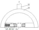
图1是本发明的结构示意图;图2是图1的A向视图的放大图;图3是图1的B向视图的放大图;图4是本发明的一种实施例的结构示意图。1 is a schematic structural diagram of the present invention; FIG. 2 is an enlarged view of the view in the direction A of FIG. 1 ; FIG. 3 is an enlarged view of the view in the direction B of FIG. 1 ; FIG. 4 is a schematic structural diagram of an embodiment of the present invention.
具体实施方式Detailed ways
为使本发明实施例的目的、技术方案和优点更加清楚,下面将结合本发明实施例中的附图,对本发明实施例中的技术方案进行清楚、完整地描述,显然,所描述的实施例是本发明一部分实施例,而不是全部的实施例。基于本发明中的实施例,本领域普通技术人员在没有作出创造性劳动前提下所获得的所有其他实施例,都属于本发明保护的范围。In order to make the purposes, technical solutions and advantages of the embodiments of the present invention clearer, the technical solutions in the embodiments of the present invention will be clearly and completely described below with reference to the accompanying drawings in the embodiments of the present invention. Obviously, the described embodiments These are some embodiments of the present invention, but not all embodiments. Based on the embodiments of the present invention, all other embodiments obtained by those of ordinary skill in the art without creative efforts shall fall within the protection scope of the present invention.
一种羽毛球体育训练器材,如图所示,包括长筒1,长筒1的两端开口,长筒1的顶部一侧开设条形槽2,条形槽2分别同时与长筒1内部、外界相通,长筒1的顶部另一侧开设第一弧形槽3,第一弧形槽3与长筒1内部相通,长筒1的底部一侧固定安装短筒4,短筒4的一端开口,短筒4与长筒1的中心线相互平行,短筒4的外周顶部开设第二弧形槽5,第二弧形槽5与短筒4内部相通,短筒4的内端固定连接数个第一电推杆6的一端,短筒4内设有锥形管7,锥形管7与短筒4的中心线共线且锥形管7的尖端朝向短筒4的开口端,锥形管7与第一电推杆6的活动端固定连接,锥形管7的内端固定连接折叠管8的一端,折叠管8能够伸缩。折叠管8与锥形管7内部相通,折叠管8的另一端固定连接储气罐9的一端,折叠管8的另一端内固定安装电动阀门,储气罐9从短筒4内穿过,储气罐9与短筒4固定连接,长筒1的底部固定安装气泵10,气泵10的出气口与储气罐9的另一端固定连接,储气罐9分别同时与折叠管8、气泵10内部相通,长筒1的顶部固定连接竖板11的底面,竖板11的一侧固定连接第二电推杆12的一端,第二电推杆12的另一端固定连接第三电推杆13的外周上部,第三电推杆13的活动端朝下且固定连接盖板14的顶部,盖板14为弧形结构且其凹面朝下。盖板14能够扣合在第二弧形槽5上,盖板14的内壁固定安装夹持装置,该结构能够夹取长筒1内的羽毛球并通过第二弧形槽5放入短筒4内,长筒1的顶部固定安装顶料构件,顶料构件从条形槽2内穿过,顶料构件每次工作均能够使长筒1内所有的羽毛球向夹持装置移动一工位,工位长度为羽毛球球托的长度,长筒1的底部另一侧固定安装矩形块15,矩形块15的前面开设通透的圆形槽16,圆形槽16的内壁内侧固定安装触点开关,触点开关与电动阀门电路连接,圆形槽16的顶面内侧通过扭簧安装扳机17,扳机17能够朝向触点开关运动且触碰触点开关,矩形块15的底面固定安装把手18,把手18与矩形块15为一体结构。本发明由陪练者操控使用,手动控制短筒4的朝向,即控制羽毛球的飞行方向,趣味性更强,克服传统结构中单次发射的弊端,能够实现羽毛球的连续发射,使练习者能够持续击球,提高训练效果,且本发明还能够进行趣味性的射击游戏,发射物为羽毛球,不会对人造成伤害,练习者躲避羽毛球,能够用来训练练习者的步伐。本发明用户先取下顶料构件,然后将数个羽毛球插接后塞入长筒1内,再将顶料构件装回,控制第一电推杆6收缩,第一电推杆6带动锥形管7移动,以使锥形管7从第二弧形槽5内脱离,夹持装置夹持最右侧的羽毛球并将之放入短筒4内,盖板14位于第二弧形槽5内,能够使短筒4处于较为封闭的状态,以减少漏气量,启动气泵10,气泵10向储气罐9内充气,储气罐9位于短筒4外的外周固定安装气压计,气压计用以监测储气罐9内的气压,当储气罐9内的气压达到限定值后关闭气泵10,然后控制第一电推杆6伸展,使锥形管7插入羽毛球内,用户握住把手,食指放入圆形槽16内并扣动扳机17,扳机17打开触电开关,触电开关控制折叠管8内的电动阀门打开,储气罐9内的气体通过折叠管8、锥形管7高速喷出,从而能够使羽毛球沿短筒4的方向飞出。长筒1的长度为50-60CM,能够储存23-30个羽毛球,储球量多,长筒1与短筒4的内径均略小于羽毛球的最大直径,以免羽毛球滑出长筒1、短筒4,通过夹持装置能够实现羽毛球的装填,且不会折断羽毛球的羽毛,有利于延长羽毛球的使用寿命,从而降低训练成本;储气罐9能够进一步提高空气冲击的动能,从而有利于提高羽毛器的射速,有利于练习者适应高速球打法;陪练者一手握持把手18,另一只手托住短筒4即可,调整短筒4的朝向即调整羽毛球的射击方向,且陪练者能够前后移动,实际操作时的灵活性更强,更不便于练习者把握设备的出球方向,从而避免造成练习者定式移动击球,不会使练习者出现死板应对的情况;本发明采用枪械射击式的发球方式,陪练者在发球过程中不会机械式操作,不利于陪练者产生枯燥情绪。A badminton sports training equipment, as shown in the figure, comprises a
具体而言,如图2所示,本实施例所述的夹持装置为两个套筒19,套筒19分别固定安装在盖板14的内壁,且两个套筒19的中心线共线,套筒19内分别设有活动杆20,活动杆20能够分别沿对应的套筒19纵向移动,活动杆20均为铁质材料,套筒19内分别固定安装电磁线圈,活动杆20分别从电磁线圈内穿过,活动杆20的外端分别固定安装夹板21,夹板21均为弧形结构,且夹板21的弧面相对,套筒19的内端分别固定连接弹簧22的一端,弹簧22的另一端均与对应的夹板21固定连接,活动杆20分别从对应的弹簧22内穿过。第二电推杆12和第三电推杆13收缩过程中使电磁线圈通电,电磁线圈通电产生磁场,能够吸附活动杆21向套筒19内移动,从而使得两个夹板21分离,当第二电推杆12、第三电推杆13完全收缩后,电磁线圈断电,弹簧22使夹板21相互靠拢从而夹紧羽毛球的球托。盖板14内固定安装ARM微处理器,ARM微处理器分别与第二电推杆12、第三电推杆13、电磁线圈电路连接,夹板21内固定安装感应器,用以感应球托是否进入夹板21范围,盖板14内固定安装传感器,传感器用以监测羽毛球是否从短筒4内飞出,传感器、感应器均与ARM微处理器电路连接,ARM微处理器首先控制电磁线圈通电,当感应器感应到球托位于夹板21之间后,ARM微处理器控制电磁线圈断电,然后ARM微处理器控制第二电推杆12完全伸展再控制第三电推杆13完全伸展,从而使盖板14扣合在第二弧形槽5内,当传感器检测到羽毛球经过后,ARM微处理器控制第三电推杆13收缩,然后再控制第二电推杆12收缩同时控制电磁线圈通电,重复上述操作。该结构使得羽毛球的装填具有周期性,从而循环将羽毛球从长筒1内取出后装入短筒4内,实现羽毛球的自动装填,无需人们手动装填,实际使用时更为方便快捷,客户体验度高。Specifically, as shown in FIG. 2 , the clamping device described in this embodiment is two
具体的,如图1或3所示,本实施例所述的顶料构件包括数个链轮23,其中一个链轮23带有动力装置,动力装置为步进电机,链轮23之间通过链板24连接,长筒1内设有与之中心线共线的圆板25,圆板25的内侧固定连接顶杆26的一端,顶杆26与圆板25的中心线共线,顶杆26的另一端与最外侧的羽毛球的球托接触,圆板25的顶部固定连接竖杆27的下端,竖杆27从条形槽2内穿过,竖杆27的一侧开设通孔28,链板24的外周固定连接L型杆29的一端,L型杆29从通孔28内穿过。L型杆29的水平杆外周与通孔28的内壁接触,链板24自上而下看顺时针转动,L型杆29的纵向杆外周与竖杆27的外周接触,从而能够带动竖杆27向竖板11方向移动,竖杆27通过圆板25带动顶杆26移动,从而使得羽毛球移动。电机电路连接时控开关,触点开关与时控开关电路连接,扳机17触动触点开关时,电机开始工作且一段时间后停止工作,能够使电机每次的工作时长相同,从而使链轮23每次的转动角度、链板24和L型杆29以及竖杆27的移动距离相同,即可使羽毛球队列精准前移,更有利于夹持装置捕捉羽毛球,且该结构能够手动控制回移并将之移出长筒1外,实际操作时非常方便。Specifically, as shown in FIG. 1 or 3, the ejector member described in this embodiment includes
进一步的,如图3所示,本实施例所述的圆板25的外周固定连接数个支杆30的一端,支杆30的另一端分别固定安装滚轮31,滚轮31的外周均与长筒1的内壁接触。该结构能够进一步提高圆板25移动过程的稳定性,数个支杆30和滚轮31相互配合,能够使圆板25的中心线始终与长筒1的中心线共线。Further, as shown in FIG. 3 , the outer circumference of the
更进一步的,如图4所示,本实施例所述的长筒1的前后两面分别固定连接转轴32的一端,长筒1的下方设有U型座33,U型座33的开口朝上,转轴32的另一端分别通过轴承连接U型座33的内壁,U型座33的底面通过轴承连接支撑杆34的上端,支撑杆34的下端固定连接底座35的顶面。底座35放置在地面上,用户握住把手18能够带动长筒1移动,长筒1能够以转轴32为中心转动,同时能够以支撑杆34为中心转动,通过底座35、支撑杆34、U型座33和转轴32对本装置进行支撑,用户操作时更为省力,能够进一步降低陪练者的劳动强度。Further, as shown in FIG. 4 , the front and rear surfaces of the
更进一步的,为了防止用户手心出汗导致打滑,本实施例所述的把手18的外周开设防滑纹。该结构能够增加把手18与人手之间的摩擦力,从而降低打滑发生的几率。Furthermore, in order to prevent slippage caused by sweating of the palm of the user's palm, the outer periphery of the
更进一步的,为了提升本装置的精准度,本实施例所述的长筒1的前面固定安装瞄具。该结构能够提升本装置发射羽毛球的精准度,用本装置进行趣味射击游戏时,打击精准度也会有所提高。Furthermore, in order to improve the accuracy of the device, sights are fixedly installed on the front of the
最后应说明的是:以上实施例仅用以说明本发明的技术方案,而非对其限制;尽管参照前述实施例对本发明进行了详细的说明,本领域的普通技术人员应当理解:其依然可以对前述各实施例所记载的技术方案进行修改,或者对其中部分技术特征进行等同替换;而这些修改或者替换,并不使相应技术方案的本质脱离本发明各实施例技术方案的精神和范围。Finally, it should be noted that the above embodiments are only used to illustrate the technical solutions of the present invention, but not to limit them; although the present invention has been described in detail with reference to the foregoing embodiments, those of ordinary skill in the art should understand that it can still be The technical solutions described in the foregoing embodiments are modified, or some technical features thereof are equivalently replaced; and these modifications or replacements do not make the essence of the corresponding technical solutions deviate from the spirit and scope of the technical solutions of the embodiments of the present invention.
Claims (7)
Priority Applications (1)
| Application Number | Priority Date | Filing Date | Title |
|---|---|---|---|
| CN201910059305.2ACN109847315B (en) | 2019-01-22 | 2019-01-22 | Badminton sports training equipment |
Applications Claiming Priority (1)
| Application Number | Priority Date | Filing Date | Title |
|---|---|---|---|
| CN201910059305.2ACN109847315B (en) | 2019-01-22 | 2019-01-22 | Badminton sports training equipment |
Publications (2)
| Publication Number | Publication Date |
|---|---|
| CN109847315A CN109847315A (en) | 2019-06-07 |
| CN109847315Btrue CN109847315B (en) | 2020-09-25 |
Family
ID=66895636
Family Applications (1)
| Application Number | Title | Priority Date | Filing Date |
|---|---|---|---|
| CN201910059305.2AExpired - Fee RelatedCN109847315B (en) | 2019-01-22 | 2019-01-22 | Badminton sports training equipment |
Country Status (1)
| Country | Link |
|---|---|
| CN (1) | CN109847315B (en) |
Families Citing this family (2)
| Publication number | Priority date | Publication date | Assignee | Title |
|---|---|---|---|---|
| CN112774165B (en)* | 2021-01-21 | 2022-01-28 | 湖南第一师范学院 | Free angle service device for badminton training |
| CN116678777B (en)* | 2023-08-03 | 2023-10-03 | 常州富安切削技术有限公司 | Wear resistance testing device and method for PVD (physical vapor deposition) cutter coating |
Citations (13)
| Publication number | Priority date | Publication date | Assignee | Title |
|---|---|---|---|---|
| US5507271A (en)* | 1993-06-16 | 1996-04-16 | Actor; James M. | Air-actuated ball-throwing device and method therefor |
| US6419589B1 (en)* | 1999-06-21 | 2002-07-16 | Ronald Carter | Automatic golf ball placement device |
| CN202105398U (en)* | 2011-05-11 | 2012-01-11 | 万厚全 | Ball supply system of badminton machine |
| CN104383670A (en)* | 2014-07-15 | 2015-03-04 | 广州大学 | Intelligent robot capable of automatically launching table tennis balls |
| US9010309B2 (en)* | 2011-11-02 | 2015-04-21 | Toca, Llc | Ball throwing machine and method |
| CN205886152U (en)* | 2016-07-28 | 2017-01-18 | 冯艾凝 | Link crossbow table tennis transmitter |
| CN107875615A (en)* | 2017-11-17 | 2018-04-06 | 电子科技大学 | A kind of intelligent badminton service robot |
| CN108325181A (en)* | 2018-01-18 | 2018-07-27 | 深圳市普尚健康技术有限公司 | A kind of shuttlecock training equipment |
| CN108404391A (en)* | 2018-04-03 | 2018-08-17 | 湖南文理学院 | A kind of athletic training vollyball catapult-launching gear |
| CN108525266A (en)* | 2018-05-20 | 2018-09-14 | 邵阳学院 | A kind of football training pass work device and method |
| CN208049341U (en)* | 2018-04-18 | 2018-11-06 | 齐鲁师范学院 | A kind of shuttlecock training multi-angle badminton launcher |
| CN108815822A (en)* | 2018-08-29 | 2018-11-16 | 山东科技大学 | A kind of tennis service machine people issuing banana kick |
| CN109011501A (en)* | 2018-09-19 | 2018-12-18 | 温州大学苍南研究院 | A kind of badminton service robot device people |
Family Cites Families (2)
| Publication number | Priority date | Publication date | Assignee | Title |
|---|---|---|---|---|
| US20050188977A1 (en)* | 2004-02-27 | 2005-09-01 | Wygant Steven J. | Pneumatic shooting device |
| US10247511B2 (en)* | 2017-02-01 | 2019-04-02 | X Products Llc | Projectile launcher |
- 2019
- 2019-01-22CNCN201910059305.2Apatent/CN109847315B/ennot_activeExpired - Fee Related
Patent Citations (13)
| Publication number | Priority date | Publication date | Assignee | Title |
|---|---|---|---|---|
| US5507271A (en)* | 1993-06-16 | 1996-04-16 | Actor; James M. | Air-actuated ball-throwing device and method therefor |
| US6419589B1 (en)* | 1999-06-21 | 2002-07-16 | Ronald Carter | Automatic golf ball placement device |
| CN202105398U (en)* | 2011-05-11 | 2012-01-11 | 万厚全 | Ball supply system of badminton machine |
| US9010309B2 (en)* | 2011-11-02 | 2015-04-21 | Toca, Llc | Ball throwing machine and method |
| CN104383670A (en)* | 2014-07-15 | 2015-03-04 | 广州大学 | Intelligent robot capable of automatically launching table tennis balls |
| CN205886152U (en)* | 2016-07-28 | 2017-01-18 | 冯艾凝 | Link crossbow table tennis transmitter |
| CN107875615A (en)* | 2017-11-17 | 2018-04-06 | 电子科技大学 | A kind of intelligent badminton service robot |
| CN108325181A (en)* | 2018-01-18 | 2018-07-27 | 深圳市普尚健康技术有限公司 | A kind of shuttlecock training equipment |
| CN108404391A (en)* | 2018-04-03 | 2018-08-17 | 湖南文理学院 | A kind of athletic training vollyball catapult-launching gear |
| CN208049341U (en)* | 2018-04-18 | 2018-11-06 | 齐鲁师范学院 | A kind of shuttlecock training multi-angle badminton launcher |
| CN108525266A (en)* | 2018-05-20 | 2018-09-14 | 邵阳学院 | A kind of football training pass work device and method |
| CN108815822A (en)* | 2018-08-29 | 2018-11-16 | 山东科技大学 | A kind of tennis service machine people issuing banana kick |
| CN109011501A (en)* | 2018-09-19 | 2018-12-18 | 温州大学苍南研究院 | A kind of badminton service robot device people |
Also Published As
| Publication number | Publication date |
|---|---|
| CN109847315A (en) | 2019-06-07 |
Similar Documents
| Publication | Publication Date | Title |
|---|---|---|
| KR101434251B1 (en) | Shuttlecock automatic collecting and carrying apparatus for badminton exercising | |
| CN109847315B (en) | Badminton sports training equipment | |
| KR101915052B1 (en) | Badminton exercise device | |
| KR100915299B1 (en) | Badminton practice system | |
| KR101134187B1 (en) | Badminton Lesson Devices | |
| JP2013099517A (en) | Mechanical baseball tee | |
| CN110302517A (en) | A tennis ball serving device for sports training | |
| CN206081556U (en) | Jet tennis service robot | |
| CN109966722A (en) | A kind of auxiliary device for shooting training | |
| US20190176008A1 (en) | Squash ball launching machine | |
| CA2068760A1 (en) | Pneumatically operated golf ball tee | |
| CN111298416A (en) | Automatic basketball serving device | |
| KR101647118B1 (en) | Volleyball Practice equipment | |
| CN111330242A (en) | Professional shooting training device | |
| CN110279997B (en) | A basketball fixed-point shooting scoring training device | |
| CN203389313U (en) | Shooting automatic ball giving machine | |
| CN103801066A (en) | Ball throwing device for tennis service practices | |
| KR200306604Y1 (en) | A badminton training device | |
| CN211986976U (en) | University student's basketball fixed point training device of shooting | |
| US20070072703A1 (en) | Baseball retreival apparatus | |
| CN210963809U (en) | Basketball collection device based on training | |
| CN110772777A (en) | Automatic service robot for badminton training | |
| US20160144261A1 (en) | System and Method for Playing a Golf Game | |
| CN207970431U (en) | A kind of stable type badminton net with automatically picking up balls function | |
| CN201399216Y (en) | Baseball and softball training aids |
Legal Events
| Date | Code | Title | Description |
|---|---|---|---|
| PB01 | Publication | ||
| PB01 | Publication | ||
| SE01 | Entry into force of request for substantive examination | ||
| SE01 | Entry into force of request for substantive examination | ||
| GR01 | Patent grant | ||
| GR01 | Patent grant | ||
| CF01 | Termination of patent right due to non-payment of annual fee | Granted publication date:20200925 | |
| CF01 | Termination of patent right due to non-payment of annual fee |