CN109843154B - Measuring device and apparatus for measuring changes in chromophore concentration - Google Patents
Measuring device and apparatus for measuring changes in chromophore concentrationDownload PDFInfo
- Publication number
- CN109843154B CN109843154BCN201780064317.3ACN201780064317ACN109843154BCN 109843154 BCN109843154 BCN 109843154BCN 201780064317 ACN201780064317 ACN 201780064317ACN 109843154 BCN109843154 BCN 109843154B
- Authority
- CN
- China
- Prior art keywords
- light
- devices
- light source
- measurement apparatus
- measurement
- Prior art date
- Legal status (The legal status is an assumption and is not a legal conclusion. Google has not performed a legal analysis and makes no representation as to the accuracy of the status listed.)
- Active
Links
Images


Classifications
- A—HUMAN NECESSITIES
- A61—MEDICAL OR VETERINARY SCIENCE; HYGIENE
- A61B—DIAGNOSIS; SURGERY; IDENTIFICATION
- A61B5/00—Measuring for diagnostic purposes; Identification of persons
- A61B5/103—Measuring devices for testing the shape, pattern, colour, size or movement of the body or parts thereof, for diagnostic purposes
- A61B5/1032—Determining colour of tissue for diagnostic purposes
- A—HUMAN NECESSITIES
- A61—MEDICAL OR VETERINARY SCIENCE; HYGIENE
- A61B—DIAGNOSIS; SURGERY; IDENTIFICATION
- A61B5/00—Measuring for diagnostic purposes; Identification of persons
- A61B5/0059—Measuring for diagnostic purposes; Identification of persons using light, e.g. diagnosis by transillumination, diascopy, fluorescence
- A61B5/0075—Measuring for diagnostic purposes; Identification of persons using light, e.g. diagnosis by transillumination, diascopy, fluorescence by spectroscopy, i.e. measuring spectra, e.g. Raman spectroscopy, infrared absorption spectroscopy
- A—HUMAN NECESSITIES
- A61—MEDICAL OR VETERINARY SCIENCE; HYGIENE
- A61B—DIAGNOSIS; SURGERY; IDENTIFICATION
- A61B5/00—Measuring for diagnostic purposes; Identification of persons
- A61B5/0002—Remote monitoring of patients using telemetry, e.g. transmission of vital signals via a communication network
- A—HUMAN NECESSITIES
- A61—MEDICAL OR VETERINARY SCIENCE; HYGIENE
- A61B—DIAGNOSIS; SURGERY; IDENTIFICATION
- A61B5/00—Measuring for diagnostic purposes; Identification of persons
- A61B5/145—Measuring characteristics of blood in vivo, e.g. gas concentration or pH-value ; Measuring characteristics of body fluids or tissues, e.g. interstitial fluid or cerebral tissue
- A61B5/1455—Measuring characteristics of blood in vivo, e.g. gas concentration or pH-value ; Measuring characteristics of body fluids or tissues, e.g. interstitial fluid or cerebral tissue using optical sensors, e.g. spectral photometrical oximeters
- A61B5/14551—Measuring characteristics of blood in vivo, e.g. gas concentration or pH-value ; Measuring characteristics of body fluids or tissues, e.g. interstitial fluid or cerebral tissue using optical sensors, e.g. spectral photometrical oximeters for measuring blood gases
- A61B5/14552—Details of sensors specially adapted therefor
- A—HUMAN NECESSITIES
- A61—MEDICAL OR VETERINARY SCIENCE; HYGIENE
- A61B—DIAGNOSIS; SURGERY; IDENTIFICATION
- A61B5/00—Measuring for diagnostic purposes; Identification of persons
- A61B5/145—Measuring characteristics of blood in vivo, e.g. gas concentration or pH-value ; Measuring characteristics of body fluids or tissues, e.g. interstitial fluid or cerebral tissue
- A61B5/1455—Measuring characteristics of blood in vivo, e.g. gas concentration or pH-value ; Measuring characteristics of body fluids or tissues, e.g. interstitial fluid or cerebral tissue using optical sensors, e.g. spectral photometrical oximeters
- A61B5/14551—Measuring characteristics of blood in vivo, e.g. gas concentration or pH-value ; Measuring characteristics of body fluids or tissues, e.g. interstitial fluid or cerebral tissue using optical sensors, e.g. spectral photometrical oximeters for measuring blood gases
- A61B5/14553—Measuring characteristics of blood in vivo, e.g. gas concentration or pH-value ; Measuring characteristics of body fluids or tissues, e.g. interstitial fluid or cerebral tissue using optical sensors, e.g. spectral photometrical oximeters for measuring blood gases specially adapted for cerebral tissue
- A—HUMAN NECESSITIES
- A61—MEDICAL OR VETERINARY SCIENCE; HYGIENE
- A61B—DIAGNOSIS; SURGERY; IDENTIFICATION
- A61B5/00—Measuring for diagnostic purposes; Identification of persons
- A61B5/24—Detecting, measuring or recording bioelectric or biomagnetic signals of the body or parts thereof
- A61B5/316—Modalities, i.e. specific diagnostic methods
- A61B5/369—Electroencephalography [EEG]
- A—HUMAN NECESSITIES
- A61—MEDICAL OR VETERINARY SCIENCE; HYGIENE
- A61B—DIAGNOSIS; SURGERY; IDENTIFICATION
- A61B5/00—Measuring for diagnostic purposes; Identification of persons
- A61B5/68—Arrangements of detecting, measuring or recording means, e.g. sensors, in relation to patient
- A61B5/6801—Arrangements of detecting, measuring or recording means, e.g. sensors, in relation to patient specially adapted to be attached to or worn on the body surface
- A61B5/6802—Sensor mounted on worn items
- A61B5/6803—Head-worn items, e.g. helmets, masks, headphones or goggles
- A—HUMAN NECESSITIES
- A61—MEDICAL OR VETERINARY SCIENCE; HYGIENE
- A61B—DIAGNOSIS; SURGERY; IDENTIFICATION
- A61B2560/00—Constructional details of operational features of apparatus; Accessories for medical measuring apparatus
- A61B2560/04—Constructional details of apparatus
- A61B2560/0443—Modular apparatus
- A—HUMAN NECESSITIES
- A61—MEDICAL OR VETERINARY SCIENCE; HYGIENE
- A61B—DIAGNOSIS; SURGERY; IDENTIFICATION
- A61B2560/00—Constructional details of operational features of apparatus; Accessories for medical measuring apparatus
- A61B2560/04—Constructional details of apparatus
- A61B2560/0456—Apparatus provided with a docking unit
- A—HUMAN NECESSITIES
- A61—MEDICAL OR VETERINARY SCIENCE; HYGIENE
- A61B—DIAGNOSIS; SURGERY; IDENTIFICATION
- A61B2562/00—Details of sensors; Constructional details of sensor housings or probes; Accessories for sensors
- A61B2562/02—Details of sensors specially adapted for in-vivo measurements
- A61B2562/0233—Special features of optical sensors or probes classified in A61B5/00
- A—HUMAN NECESSITIES
- A61—MEDICAL OR VETERINARY SCIENCE; HYGIENE
- A61B—DIAGNOSIS; SURGERY; IDENTIFICATION
- A61B2562/00—Details of sensors; Constructional details of sensor housings or probes; Accessories for sensors
- A61B2562/18—Shielding or protection of sensors from environmental influences, e.g. protection from mechanical damage
- A61B2562/182—Electrical shielding, e.g. using a Faraday cage
- A—HUMAN NECESSITIES
- A61—MEDICAL OR VETERINARY SCIENCE; HYGIENE
- A61B—DIAGNOSIS; SURGERY; IDENTIFICATION
- A61B2562/00—Details of sensors; Constructional details of sensor housings or probes; Accessories for sensors
- A61B2562/18—Shielding or protection of sensors from environmental influences, e.g. protection from mechanical damage
- A61B2562/185—Optical shielding, e.g. baffles
- A—HUMAN NECESSITIES
- A61—MEDICAL OR VETERINARY SCIENCE; HYGIENE
- A61B—DIAGNOSIS; SURGERY; IDENTIFICATION
- A61B5/00—Measuring for diagnostic purposes; Identification of persons
- A61B5/0033—Features or image-related aspects of imaging apparatus, e.g. for MRI, optical tomography or impedance tomography apparatus; Arrangements of imaging apparatus in a room
- A61B5/004—Features or image-related aspects of imaging apparatus, e.g. for MRI, optical tomography or impedance tomography apparatus; Arrangements of imaging apparatus in a room adapted for image acquisition of a particular organ or body part
- A61B5/0042—Features or image-related aspects of imaging apparatus, e.g. for MRI, optical tomography or impedance tomography apparatus; Arrangements of imaging apparatus in a room adapted for image acquisition of a particular organ or body part for the brain
- A—HUMAN NECESSITIES
- A61—MEDICAL OR VETERINARY SCIENCE; HYGIENE
- A61B—DIAGNOSIS; SURGERY; IDENTIFICATION
- A61B5/00—Measuring for diagnostic purposes; Identification of persons
- A61B5/02—Detecting, measuring or recording for evaluating the cardiovascular system, e.g. pulse, heart rate, blood pressure or blood flow
- A61B5/026—Measuring blood flow
- A61B5/0261—Measuring blood flow using optical means, e.g. infrared light
- A—HUMAN NECESSITIES
- A61—MEDICAL OR VETERINARY SCIENCE; HYGIENE
- A61B—DIAGNOSIS; SURGERY; IDENTIFICATION
- A61B5/00—Measuring for diagnostic purposes; Identification of persons
- A61B5/24—Detecting, measuring or recording bioelectric or biomagnetic signals of the body or parts thereof
- A61B5/25—Bioelectric electrodes therefor
- A61B5/279—Bioelectric electrodes therefor specially adapted for particular uses
- A61B5/291—Bioelectric electrodes therefor specially adapted for particular uses for electroencephalography [EEG]
- A—HUMAN NECESSITIES
- A61—MEDICAL OR VETERINARY SCIENCE; HYGIENE
- A61B—DIAGNOSIS; SURGERY; IDENTIFICATION
- A61B5/00—Measuring for diagnostic purposes; Identification of persons
- A61B5/40—Detecting, measuring or recording for evaluating the nervous system
- A61B5/4058—Detecting, measuring or recording for evaluating the nervous system for evaluating the central nervous system
- A61B5/4064—Evaluating the brain
Landscapes
- Health & Medical Sciences (AREA)
- Life Sciences & Earth Sciences (AREA)
- Physics & Mathematics (AREA)
- Engineering & Computer Science (AREA)
- Public Health (AREA)
- Pathology (AREA)
- Biophysics (AREA)
- Biomedical Technology (AREA)
- Heart & Thoracic Surgery (AREA)
- Medical Informatics (AREA)
- Molecular Biology (AREA)
- Surgery (AREA)
- Animal Behavior & Ethology (AREA)
- General Health & Medical Sciences (AREA)
- Veterinary Medicine (AREA)
- Spectroscopy & Molecular Physics (AREA)
- Neurology (AREA)
- Optics & Photonics (AREA)
- Computer Networks & Wireless Communication (AREA)
- Dentistry (AREA)
- Oral & Maxillofacial Surgery (AREA)
- Psychology (AREA)
- Nuclear Medicine, Radiotherapy & Molecular Imaging (AREA)
- Radiology & Medical Imaging (AREA)
- Psychiatry (AREA)
- Neurosurgery (AREA)
- Physiology (AREA)
- Measurement Of The Respiration, Hearing Ability, Form, And Blood Characteristics Of Living Organisms (AREA)
- Investigating Or Analysing Materials By Optical Means (AREA)
Abstract
Description
Translated fromChinese技术领域technical field
本公开涉及用于测量生物介质中发色团(chromophore)浓度的改变的装置和设备。The present disclosure relates to devices and apparatus for measuring changes in chromophore concentrations in biological media.
背景技术Background technique
存在许多其中能够测量生物介质中发色团浓度的改变是有用的应用。已知的装置对于受验者来说往往体积大且不舒服。已知的装置还经受低水平的信噪比,特别是因为信号强度常常非常低,而噪声水平可能非常高,这会掩盖要获得的信号。使用已知的设备和装置对生物介质中发色团的浓度成像也是困难或费力的。There are many applications in which it is useful to be able to measure changes in chromophore concentration in biological media. Known devices tend to be bulky and uncomfortable for the subject. Known devices also suffer from a low level of signal-to-noise ratio, especially since the signal strength is often very low, while the noise level can be very high, which can obscure the signal to be obtained. Imaging the concentration of chromophores in biological media is also difficult or laborious using known equipment and devices.
发明内容Contents of the invention
根据本文公开的第一方面,提供了一种用于装配到动物身体的测量装置,用于测量该动物身体内发色团浓度的改变,该测量装置包括:According to a first aspect disclosed herein, there is provided a measuring device for fitting to the body of an animal for measuring changes in the concentration of chromophores in the body of the animal, the measuring device comprising:
多个设备,每个设备具有用于向在使用中被装配了测量装置的动物身体发射光的光源、用于检测从所述动物身体返回的光的光检测器,以及用于从主控制器接收信号和向主控制器发送信号的设备控制器;以及,A plurality of devices, each having a light source for emitting light towards the body of an animal to which the measuring device is fitted in use, a light detector for detecting light returning from said animal body, and a device controller that receives signals and sends signals to the master controller; and,
连接布置,所述多个设备的设备控制器被分别连接到该连接布置。A connection arrangement to which device controllers of the plurality of devices are respectively connected.
该装置对于使用该装置的技术人员和在使用中被装配了该装置的受验者都是方便的。该装置的示例使得能够从动物身体快速收集数据并促进对所研究区域的成像。使设备控制器被提供在所述设备上促进了装置的模块化,如在一些示例中,所述设备可以更容易地被连接到装置的不同位置和从装置的不同位置移除,并因此可以在需要时或在有用时重新定位。The device is convenient for both the technician using the device and the subject to whom the device is fitted in use. Examples of this device enable rapid data collection from the animal body and facilitate imaging of the area of interest. Having a device controller provided on the device facilitates modularization of the device, as in some examples, the device can be more easily connected to and removed from different locations on the device and thus can Reposition when needed or when useful.
从所述动物身体出射的光可以是例如反射光或透射光等,所述光在每种情况下最终得自由光源发射在动物身体处或发射到动物身体内的光。一般而言,该“光”可以是可见光或不可见光。The light emerging from the animal's body can be, for example, reflected light or transmitted light etc., which ultimately results in each case from light emitted by the light source at or into the animal's body. In general, this "light" can be visible light or invisible light.
在示例中,设备的光源被布置成发射近红外光。这可以在例如600nm至1000nm的范围内。In an example, the light source of the device is arranged to emit near infrared light. This may be in the range of eg 600nm to 1000nm.
在示例中,每个设备包括至少两个光源,其中第一光源布置成发射第一波长的光并且第二光源布置成发射不同于所述第一波长的第二波长的光。在一些示例中,使用多个波长使得能够更容易地区分来自不同发色团的信号。通过具体应用中的具体示例,使用多个波长使得由于较不主要发色团导致的信号能够更容易地与由于血红蛋白(其是哺乳动物组织中最主要的发色团)导致的信号区分开,并且因此例如提供有关组织氧合、血液动力学和新陈代谢的更完整和准确的信息。In an example, each device comprises at least two light sources, wherein a first light source is arranged to emit light at a first wavelength and a second light source is arranged to emit light at a second wavelength different from said first wavelength. In some examples, the use of multiple wavelengths allows for easier differentiation of signals from different chromophores. By way of specific example in a specific application, the use of multiple wavelengths enables signals due to less dominant chromophores to be more easily distinguished from signals due to hemoglobin (which is the most dominant chromophore in mammalian tissue), And thus for example provide more complete and accurate information on tissue oxygenation, hemodynamics and metabolism.
在示例中,至少两个光源之间的距离不大于所述至少两个光源中的每一个光源与光检测器之间的距离的15%。所述光源可以作为光源单元的部件被提供。期望光源尽可能紧密地被同一定位,特别是在光源发射不同波长的情况下,因为可以以高准确度假设或至少近似所述测量对相同体积的组织进行采样。In an example, the distance between the at least two light sources is no greater than 15% of the distance between each of the at least two light sources and the light detector. The light source may be provided as part of a light source unit. It is desirable that the light sources be co-located as closely as possible, especially if the light sources emit different wavelengths, since it can be assumed with high accuracy, or at least approximated, that the measurements sample the same volume of tissue.
在示例中,连接布置至少部分地由具有多个连接器端口的共享总线提供,所述设备的至少一些设备的设备控制器被分别连接到所述多个连接器端口。共享总线可以是例如共享串行通信总线。在示例中,所述设备的至少一个设备具有用于将该设备可移除地连接到共享总线的连接器。In an example, the connection arrangement is at least partly provided by a shared bus having a plurality of connector ports to which device controllers of at least some of the devices are respectively connected. The shared bus may be, for example, a shared serial communication bus. In an example, at least one of the devices has a connector for removably connecting the device to the shared bus.
在示例中,所述设备的至少一个设备包括将该设备连接到共享总线的柔性导体。In an example, at least one of said devices comprises a flexible conductor connecting the device to a shared bus.
在示例中,连接布置至少部分地由布线方案提供,其中多个设备按顺序被连接。In an example, the connection arrangement is provided at least in part by a wiring scheme in which multiple devices are connected in sequence.
在示例中,连接布置至少部分地由所述设备的至少一些设备之间的无线连接提供。In an example, the connection arrangement is at least partly provided by a wireless connection between at least some of said devices.
在示例中,该装置包括多个坞(dock),每个坞用于可移除地接纳相应的设备。所述坞的至少一些坞可以包括电连接器,用于在连接布置和在坞中接纳的设备的设备控制器之间建立连接。In an example, the apparatus includes a plurality of docks, each dock for removably receiving a respective device. At least some of the docks may comprise electrical connectors for establishing a connection between the connection arrangement and a device controller of a device received in the dock.
在示例中,所述设备包括法拉第笼,它至少封住该设备的光检测器。在为光检测器提供放大器的情况下,所述设备的法拉第笼还可以封住放大器。In an example, the device includes a Faraday cage enclosing at least a light detector of the device. Where an amplifier is provided for the photodetector, the Faraday cage of the device may also enclose the amplifier.
在示例中,每个所述设备包括:In an example, each of said devices includes:
用于光检测器的电荷-数字转换器,该电荷-数字转换器具有多个放大器及模数转换器,其中:A charge-to-digital converter for a photodetector, the charge-to-digital converter having multiple amplifiers and an analog-to-digital converter, wherein:
多个放大器被布置为产生电压输出;以及,a plurality of amplifiers arranged to generate a voltage output; and,
模数转换器被布置为读取由所述放大器之一输出的电压,而所述放大器的另一个正在累积或转换来自光检测器的电荷。这使得所述设备能够连续操作。所述放大器可以是例如电荷积分放大器。An analog-to-digital converter is arranged to read the voltage output by one of the amplifiers while the other of the amplifiers is accumulating or converting charge from the photodetector. This enables continuous operation of the device. The amplifier may be, for example, a charge integrating amplifier.
在示例中,每个所述设备包括:In an example, each of said devices includes:
用于光检测器的电流-数字转换器,该电流-数字转换器具有跨阻抗放大器和模数转换器,其中:A current-to-digital converter for a photodetector, the current-to-digital converter having a transimpedance amplifier and an analog-to-digital converter, wherein:
所述跨阻抗放大器被布置为产生电压输出;以及,the transimpedance amplifier is arranged to generate a voltage output; and,
所述模数转换器被布置为读取由所述放大器输出的电压。The analog-to-digital converter is arranged to read the voltage output by the amplifier.
在示例中,每个所述设备包括衬底,光源、光检测器和设备控制器被布置在衬底中。该衬底可以对由光源发射的光是透明的。In an example, each of said devices comprises a substrate in which a light source, a light detector and a device controller are arranged. The substrate may be transparent to light emitted by the light source.
在示例中,每个所述设备包括多个光导,其中:In an example, each said device comprises a plurality of light guides, wherein:
第一光导被布置为将来自光源的光引导到所述动物身体;以及,A first light guide is arranged to direct light from a light source to the body of the animal; and,
第二光导被布置为将来自所述动物身体的光引导到光检测器。A second light guide is arranged to direct light from the animal's body to a light detector.
在示例中,第一光导一般是圆柱形的并且被围绕光源布置。In an example, the first light guide is generally cylindrical and is arranged around the light source.
在示例中,第二光导一般是圆柱形的并且被围绕光检测器布置。In an example, the second light guide is generally cylindrical and is arranged around the light detector.
第一和第二光导可以作为分开的部件的一部分提供,该部分可以可移除地放置在光源和光检测器上。这使得光导能够容易地被移除以便清洁或更换(例如,在对不同的受验者或生物介质使用之前)。The first and second light guides may be provided as part of a separate component which may be removably placed over the light source and light detector. This enables the light guide to be easily removed for cleaning or replacement (eg, prior to use on a different subject or biological medium).
在示例中,每个设备的设备控制器是微控制器,并且每个设备包括用于存储从主控制器和光检测器中的至少一个接收的数据的本地存储器。该本地存储器可以是微控制器的一部分和/或与微控制器分开提供。In an example, the device controller of each device is a microcontroller, and each device includes local memory for storing data received from at least one of the main controller and the light detector. The local memory may be part of the microcontroller and/or provided separately from the microcontroller.
在示例中,设备控制器被布置为根据从主控制器接收的信号将信号发送到光源,并且被布置为根据从光检测器接收的信号将信号发送到主控制器。In an example, the device controller is arranged to send a signal to the light source based on a signal received from the main controller, and is arranged to send a signal to the main controller based on a signal received from the light detector.
在示例中,所述信号包括光源强度指令、时钟信号和数据信号中的至少一个。In an example, the signal includes at least one of a light source intensity command, a clock signal, and a data signal.
在示例中,至少一个设备包括电极,该电极被布置为测量在介质中产生的电信号,以便非侵入性地监视在该介质中的电活动。该设备可以被用于获得例如同时脑电图(EEG)测量。In an example, at least one device comprises electrodes arranged to measure electrical signals generated in the medium for non-invasively monitoring electrical activity in the medium. The device can be used to obtain, for example, simultaneous electroencephalography (EEG) measurements.
在示例中,该装置包括:In an example, the device includes:
主控制器,用于向所述设备发送信号和从所述设备接收信号;以及,a master controller for sending signals to and receiving signals from said device; and,
被布置在主控制器和所述设备的至少一个设备之间的连接,该连接被布置为在主控制器和所述设备之间中继信号,该信号包括光源强度指令、时钟信号和数据信号中的至少一个;a connection arranged between the master controller and at least one of said devices, the connection being arranged to relay signals between the master controller and said devices, the signals comprising light source intensity commands, clock signals and data signals at least one of;
主控制器被布置为生成系统时钟并发起与所述设备的通信。The master controller is arranged to generate a system clock and initiate communication with the device.
根据本文公开的第二方面,提供了一种用于与如上所述的测量装置一起使用的用于测量生物介质中发色团浓度的改变的设备,该设备包括:According to a second aspect disclosed herein, there is provided an apparatus for measuring changes in chromophore concentration in a biological medium for use with a measuring device as described above, the apparatus comprising:
用于朝着生物介质发射光的光源;a light source for emitting light towards the biological medium;
用于检测从所述生物介质出射的光的光检测器;以及,a photodetector for detecting light emitted from said biological medium; and,
用于从主控制器接收信号和向主控制器发送信号的设备控制器。A device controller for receiving signals from and sending signals to the master controller.
这种设备实际上至少在很大程度上是自足单元(self-contained unit)。使设备控制器被提供在设备上促进了装置的模块化,在实践中以此可以使用多个这样的设备。Such devices are in practice at least largely self-contained units. Having the device controller provided on the device facilitates modularity of the apparatus whereby in practice a plurality of such devices can be used.
在示例中,光源被布置为发射近红外光。这可以在例如600nm至1000nm的范围内。In an example, the light source is arranged to emit near infrared light. This may be in the range of eg 600nm to 1000nm.
在示例中,该设备包括至少两个光源,其中第一光源被布置为发射第一波长的光并且第二光源被布置为发射不同于所述第一波长的第二波长的光。In an example, the device comprises at least two light sources, wherein a first light source is arranged to emit light at a first wavelength and a second light source is arranged to emit light at a second wavelength different from said first wavelength.
在示例中,该设备具有用于将设备可移除地连接到总线的连接器。该总线可以是例如串行通信总线。In an example, the device has a connector for removably connecting the device to the bus. The bus may be, for example, a serial communication bus.
在示例中,该设备具有无线收发器,用于将该设备无线地连接到另一个设备,如上所述。在其示例中,该设备可以具有其自己的电源,诸如电池,该电池可以是可再充电电池或不可再充电电池,实际上使得该设备成为自足的测量设备。In an example, the device has a wireless transceiver for wirelessly connecting the device to another device, as described above. In its example, the device may have its own power source, such as a battery, which may be rechargeable or non-rechargeable, effectively making the device a self-contained measurement device.
附图说明Description of drawings
为了帮助理解本公开并示出如何可以实施实施例,通过示例的方式参考附图,其中:To facilitate an understanding of the present disclosure and to illustrate how embodiments may be practiced, reference is made, by way of example, to the accompanying drawings, in which:
图1示出了用于测量生物介质中发色团的浓度的改变的系统的示例的示意性视图;Figure 1 shows a schematic view of an example of a system for measuring changes in the concentration of a chromophore in a biological medium;
图2示出了与用于测量生物介质中发色团的浓度的改变的装置一起使用的设备的示例的示意性透视图;Figure 2 shows a schematic perspective view of an example of a device used with a device for measuring changes in the concentration of a chromophore in a biological medium;
图3示出了图2的设备的面的示意性视图;Figure 3 shows a schematic view of a face of the device of Figure 2;
图4示出了与用于测量生物介质中发色团的浓度的改变的装置一起使用的光导的示例的示意性横截面视图;Figure 4 shows a schematic cross-sectional view of an example of a light guide used with a device for measuring changes in the concentration of a chromophore in a biological medium;
图5示出了用于测量生物介质中发色团的浓度的改变的装置的示例的另一个示意性视图;Figure 5 shows another schematic view of an example of a device for measuring changes in the concentration of a chromophore in a biological medium;
图6示出了与用于测量生物介质中发色团的浓度的改变的装置一起使用的设备的另一个示例的侧视图,该设备与坞和光导布置组装在一起;Figure 6 shows a side view of another example of an apparatus for use with a device for measuring changes in the concentration of a chromophore in a biological medium, assembled with a dock and light guide arrangement;
图7示出了图6的组件的VII-VII的截面视图;Figure 7 shows a cross-sectional view VII-VII of the assembly of Figure 6;
图8A至8C示出了以拆卸形式的图6的设备、坞和光导布置的透视图;Figures 8A to 8C show perspective views of the device, dock and light guide arrangement of Figure 6 in disassembled form;
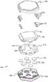
图9示出了图8A的设备的分解视图;Figure 9 shows an exploded view of the device of Figure 8A;
图10A和10B分别示出了从图8A的设备的组装电路板的上方和下方看的透视图;Figures 10A and 10B show perspective views, respectively, from above and below the assembled circuit board of the device of Figure 8A;
图11示出了图8B的坞的分解视图;以及Figure 11 shows an exploded view of the dock of Figure 8B; and
图12示出了具有图8B的坞的帽子或头饰的示例,该坞用于接纳图8A的设备和图8B的光导。Figure 12 shows an example of a hat or headgear with the dock of Figure 8B for receiving the device of Figure 8A and the light guide of Figure 8B.
具体实施方式Detailed ways
如上面所提到的,存在许多其中能够测量生物介质中发色团浓度的改变是有用的应用。例如,测量动物身体尤其是包括人体内发色团浓度的改变会是有用的,其中例如可以在流过大脑或心脏或骨骼肌等等的血液等等中发现发色团。As mentioned above, there are many applications where it is useful to be able to measure changes in chromophore concentration in biological media. For example, it would be useful to measure changes in the concentration of chromophores in the body of animals, especially humans, where chromophores may be found, for example, in blood flowing through the brain or heart or skeletal muscle and the like.
作为一个特定示例,用于执行旨在测量区域大脑活动的功能性神经成像的装置是已知的。功能性近红外光谱(fNIRS)是一种已知的非侵入性技术,用于提供关于大脑活动的血管和代谢反应的信息。发色团可以是或包括例如氧合血红蛋白、脱氧血红蛋白和氧化细胞色素c氧化酶。氧合血红蛋白和脱氧血红蛋白在血液中被找到。氧化细胞色素c氧化酶可以在组织中被找到。测量这些发色团浓度的改变可以提供对例如大脑活动区域的了解。As a specific example, devices are known for performing functional neuroimaging aimed at measuring regional brain activity. Functional near-infrared spectroscopy (fNIRS) is a known non-invasive technique used to provide information on vascular and metabolic responses to brain activity. The chromophore can be or include, for example, oxyhemoglobin, deoxyhemoglobin, and oxidized cytochrome c oxidase. Oxyhemoglobin and deoxyhemoglobin are found in blood. Oxidative Cytochrome c oxidase can be found in tissues. Measuring changes in the concentration of these chromophores can provide insight into, for example, active regions of the brain.
已知的fNIRS系统通常涉及将大的光纤阵列或纤维束耦合到头皮。在整个头皮上成像通常需要大约30个离散的源位置和相似数量的检测器位置,这通常导致笨重且严重限制移动的阵列。最近,已经开发了便携式系统,其采用与头皮直接接触的源和检测器,模拟信号经由长电缆被传送到控制器模块。这种方案的一个问题是长模拟电缆会把噪声引入测量中。利用已知的fNIRS系统对发色团的浓度进行成像也是困难或费力的。遭受此类研究的患者或其他人或动物不可避免地常常不愿遭受长时段的研究,或者甚至不能被进行长时段研究。Known fNIRS systems typically involve coupling a large array or bundle of fibers to the scalp. Imaging across the entire scalp typically requires around 30 discrete source locations and a similar number of detector locations, often resulting in bulky and severely limited movement of the array. More recently, portable systems have been developed that employ sources and detectors in direct contact with the scalp, with the analog signal being transmitted to a controller module via a long cable. One problem with this approach is that long analog cables introduce noise into the measurement. Imaging the concentration of chromophores is also difficult or laborious using known fNIRS systems. Inevitably, patients or other humans or animals subjected to such studies are often unwilling to be subjected to prolonged studies, or cannot even be subjected to prolonged studies.
本文描述的装置100的示例可以被用于测量生物介质中发色团浓度的改变。这又可以使得能够随时间监视生物介质中发色团浓度的改变。此外,本文描述的装置100的示例可以被用于使得能够产生并且实时产生在生物介质中的发色团的浓度的图像,这对于从业者具有重要价值。Examples of
参考图1,示出了用于测量身体内发色团浓度的改变的装置100的示例的示意视图。该示例中的装置100具有至少一个设备120和总线150,装置100在使用中与基础单元160通信,基础单元160又与诸如计算机170之类的数据记录器通信。基础单元160可以用作装置100的“集线器”或主机或主控制器。Referring to FIG. 1 , a schematic view of an example of an
在典型的实现中,装置100具有多个设备120,它们完全相同或至少具有基本相同的功能,并且总线150是所有设备120所连接到的共享总线150。在该图中,仅示出了装置100的一部分和四个设备120。在实践中,通常会有比如说大约20到30个或更多这样的设备120。设备120通过共享总线150彼此连接,共享总线150还连接到基础单元160。在所示的示例中,基础单元160通过无线链路180连接到计算机170。基础单元160可以具有其自己的电源,诸如电池,电池可以是可再充电电池或不可再充电电池。基础单元160的电源可以为基础单元160的部件供电,并且可选地还为设备120供电(虽然在一些示例中设备120可以具有其自己的电源,诸如可再充电电池或不可再充电电池)。基础单元160和计算机170之间的无线链路180,以及为基础单元160和设备120提供它们自己的一个(或多个)电源更方便,因为这意味着设备120和基础单元160(其本身可以相对小且重量轻)的组合可以被有效地解开(untethered),并且因此实现可穿戴和便携两者。这对于使用该系统的技术人员和所研究的人或其他受验者来说都是方便的,如果期望,那么他们能够相对自由地走来走去。不过,在其它实现中,可以代替地使用到计算机170的有线连接和/或提供用于为基础单元160和/或设备120供电的某个外部电源。设备120可以是块或“瓦片(tile)”的形式,这促进装置100的模块化,因为可以根据期望或需要添加或移除单独设备120。In a typical implementation, the
另外参考图2和3,示出了设备120的示例的示意视图。在这个示例中,设备120一般而言是长方体,具有矩形或正方形的截面形状。设备120具有至少一个光源单元122和至少一个光检测器单元124。在这些图中所示的具体示例中,设备120具有两个光源单元122和四个光检测器单元124。每个光源单元122具有或包含用于发射光的至少一个光源123。在示例中,光源单元122具有多个光源123。在具体示例中,每个光源单元122具有两个光源123。每个光源123可以发射具有在例如大约600nm至1000nm范围内的波长的光。光源123可以发射具有不同波长的光。在示例中,每个光源单元122具有可以发射第一波长的光的第一光源123和可以发射第二波长的光的第二光源123。光源123可以是例如发光二极管(LED)。光检测器单元124被布置为检测具有由光源123发射的波长的光。在所示的示例中,光源单元122和光检测器单元124被安装在衬底130中或由衬底130支撑,衬底130提供设备120的主体的大部分。衬底130可以是例如黑色着色的硅酮。Referring additionally to Figures 2 and 3, schematic views of examples of
在使用中,光源123朝向其中存在发色团的介质发射光。在具体示例中,该介质可以是人的头部,但也可以是人或其它动物的其它身体部位。如上面所提到的,光源123可以以若干不同的离散波长发射。在fNIRS的具体示例中,已经发现使用波长大约为780nm和850nm的光分别监视氧合血红蛋白浓度和脱氧血红蛋白浓度的改变是有用的,但是可以使用不同的波长。更一般而言并且作为进一步的示例,较短的波长可以在大约650nm至780nm的范围内,并且较长的波长可以在大约820nm至900nm的范围内。In use, the
为了用装置100准确地解释数据,期望假设测量对相同体积的组织进行采样。因此,优选的是,离散波长的源尽可能紧密地同一定位。因此,与光源单元122和光检测器单元124之间的距离相比,在光源单元122中的光源123之间的间隔优选地是小的或甚至可忽略不计。在示例中,光源单元122的光源123之间的距离不大于光源单元122和一个(或多个)光检测器单元124之间的距离的15%。在一个示例中,光源单元122的光源123之间的距离不大于光源单元122和一个(或多个)光检测器单元124之间的距离的10%。在另一个示例中,光源单元122的光源123之间的距离不大于光源单元122和一个(或多个)光检测器单元124之间的距离的5%。在示例中,在光源单元122中的光源123之间的距离可以小于几毫米,而光源单元122和一个(或多个)光检测器单元124之间的距离可以高达几厘米。在具体示例中,在设备120的光源单元122中的光源123之间的距离可以在大约0mm到1mm之间,诸如大约0.3mm,而设备120的光源单元122和光检测器单元124之间的距离可以是大约8.5mm,或者至少可以是大约8.5mm的最小值。(在存在多个设备120的情况下,设备120的光源单元122与相邻设备120的光检测器单元124之间的最小距离可以是例如大约10mm至25mm。)In order to accurately interpret the data with the
对于一些应用,可以选择光源单元122和光检测器单元124的布置,使得光源单元122和光检测器单元124之间的(最短)距离是小的,诸如几毫米,诸如大约3mm或更小。光源单元122和光检测器单元124可以被紧密地定位,并且在一些情况下可以实际上被同一定位。For some applications, the arrangement of the
在光源单元122中的光源123可以由例如多路复用的压控电流源(VCCS)驱动。这使得能够准确控制流过光源123的电流,这与光源123的光强度密切相关。使用模拟多路复用器代替分立晶体管以在光源123之间切换。多路复用VCCS方案比传统的电阻器/运算放大器组合更紧凑和灵活。The
每个光检测器单元124具有用于检测光的至少一个光检测器125,其可以是例如光电二极管。在所示的示例中,每个光检测器单元124具有单个光检测器125。在具体示例中,设备120的光检测器单元124的四个光电二极管检测器125被耦合到四通道电荷-数字转换器的相应通道,四通道电荷-数字转换器包括每个通道两个电荷积分器和至少一个模数转换器(ADC)并且可以被提供在设备120上。在具体示例中,设备120具有两个ADC。电荷积分器(也称为电荷放大器或电荷积分放大器)对由入射光生成的光电二极管电流进行积分以输出电压。每个通道两个并联电荷积分器的使用使得一个电荷积分器能够积分所生成的光电二极管电流,同时另一个电荷积分器的输出被ADC数字化。这促进设备120的连续操作而没有任何停滞时间。而且,因为模拟信号在信号路径中被早期数字化(即,有效地作为由光检测器单元124输出模拟信号时的第一步),所以改善了信噪比。Each
在具体示例中,电荷积分器被提供作为模数转换器的一部分,该模数转换器可以是例如Texas Instruments DDC系列的DDC114。在另一个示例中,电荷积分器是TexasInstruments DDC系列的DDC118的一部分。光检测器125被直接连接到DDC114/DDC118的高阻抗模拟输入端。与使用分立元件相比,在一个集成电路内提供成对的电荷积分器及其相关联的ADC导致优良的信噪比。In a specific example, the charge integrator is provided as part of an analog-to-digital converter, which may be, for example, a DDC 114 from the Texas Instruments DDC series. In another example, the charge integrator is part of the DDC118 of the Texas Instruments DDC family.
作为电荷积分器的使用的替代或补充,电流-电压转换器可以以跨阻抗放大器的形式用于光电二极管信号放大。在具体示例中,可以使用Texas Instruments OPA380。在具体示例中,跨阻抗放大器然后可以被连接到其自己的ADC。在另一个示例中,可以将多于一个跨阻抗放大器多路复用到具有多个输入通道的单个ADC。As an alternative or in addition to the use of a charge integrator, a current-voltage converter can be used for photodiode signal amplification in the form of a transimpedance amplifier. In a specific example, a Texas Instruments OPA380 can be used. In a specific example, the transimpedance amplifier can then be connected to its own ADC. In another example, more than one transimpedance amplifier can be multiplexed to a single ADC with multiple input channels.
设备120具有设备控制器126。示例中的设备控制器126是微控制器。设备控制器126被布置为经由总线150将源自光检测器单元124的信号发送到基础单元160。设备控制器126被布置为经由总线150从基础单元160接收信号。如所提到的,基础单元160与计算机170通信。以这种方式,计算机170可以与设备120通信。基础单元160可以向设备120发送信号,该信号包括光源强度指令、时钟信号和数据信号中的至少一个。在光源123是LED的情况下,光源强度指令可以是例如LED状态命令,其控制LED的接通和断开以及控制其照明的强度。时钟信号使得基础单元160能够使装置100的一个或多个部件同步。
在具体示例中,设备120具有用于设备控制器126的本地存储器存储装置。本地存储器存储装置可以是设备控制器126的一部分,特别是在设备控制器126是微控制器的情况下。附加地或可替代地,本地存储器存储装置可以作为分开的存储器被提供。在其中本地存储器存储装置作为分开的存储器被提供的具体示例中,设备控制器1 26与本地存储器存储装置通信。无论哪种方式,设备控制器126都可以在本地存储器中存储从光检测器单元124接收或获得的信息。设备控制器126可以附加地或可替代地将用于光源单元122的指令存储在存储器存储装置中。信息和指令可以被本地存储到设备120。In a particular example,
现在具体地参考图2和3,在这个示例中,所示的设备120具有连接器132,用于将设备120可移除地连接到总线150。在这个示例中的连接器132在设备120的衬底130中的边缘134内部被提供。连接器132可以接纳共享总线150的一部分,以将设备120连接到总线150。在所示的示例中,连接器132位于设备120的与光源单元122和光检测器单元124相对着的面上。这有助于防止共享总线150物理地干扰光源单元122和光检测器单元124的操作。Referring now specifically to FIGS. 2 and 3 , in this example,
设备120可以具有柔性或所谓的“刚挠”印刷电路板。刚挠电路是层叠在一起以形成单个结构的刚性和柔性衬底上的电路的混合结构。在这个示例中,刚挠印刷电路板具有柔性导体,其可以将设备120连接到例如基础单元160。在这个示例中,设备120因此不需要上述类型的连接器132。刚挠印刷电路板的柔性导体可以可替代地或附加地用于将一个设备120连接到另一个设备120。在示例中,设备120的整个印刷电路板被封在法拉第笼内,这减少或消除了设备120对外部电磁噪声的敏感性。下面将进一步讨论用于法拉第笼的布置的具体示例。
在示例中,设备120的一个(或多个)光源单元122和一个(或多个)光检测器单元124各自被封装在保护性聚合物诸如例如光学透明的硅酮或UV固化的环氧树脂中。在示例中,保护性聚合物对于由光源123发射的光是透明的。In an example, the light source unit(s) 122 and photodetector unit(s) 124 of
在示例中,光源单元122内的一个或多个光源123诸如LED可以被封装在保护性聚合物诸如光学透明的硅酮或UV固化的环氧树脂中。这可以被如下执行。可以制造硅酮橡胶掩模以形成用于分配液体环氧树脂的腔体。由于硅酮橡胶固有地是疏水性的,因此防止了与环氧树脂的化学键合,并且当环氧树脂完全固化时可以容易地除去掩模。掩模可以使用由0.5mm厚的激光切割丙烯腈-丁二烯-苯乙烯(ABS)制成的开放铸模来生产。在浇注铂固化硅酮高聚物之前,可以用脱模剂轻轻喷涂模具。然后可以将用于每个光源单元122的一个或多个光源123诸如LED管芯定位在硅酮中,然后硅酮被固化。可替代地,可以使用Perspex(TM)掩模来形成硅酮掩模。在具体示例中,Perspex掩模是约1.5mm厚。硅酮掩模被固化,然后被推向LED。然后可以用UV固化环氧树脂填充硅酮掩模内的窗口。In an example, one or more
LED可以是例如近红外AlGaAs pn结半导体。LED管芯使LED的n侧(阴极)朝上,而它们的相对着的p侧(阳极)被金属化以粘合到衬底。所有管芯都被附接到尺寸为2mm×2mm的方形镀金衬底上。这个区域被用作公共阳极,并且每个管芯可以通过使电流通过其阴极来单独寻址。最初,衬底涂有薄层的可热固化的导电浆料。浆料为管芯的后表面(阳极)形成电连接,并且一旦固化就提供机械固定。The LED can be, for example, a near-infrared AlGaAs pn junction semiconductor. The LED dies have the n-side (cathode) of the LEDs facing up, while their opposite p-side (anode) is metallized for adhesion to the substrate. All dies were attached to square gold-plated substrates measuring 2mm x 2mm. This area is used as a common anode, and each die can be individually addressed by passing current through its cathode. Initially, the substrate is coated with a thin layer of thermally curable conductive paste. The paste forms an electrical connection to the back surface (anode) of the die and provides a mechanical fixation once cured.
如图3中所示,光导140围绕光源单元122和光检测器单元124中的至少一些并且优选地每一个布置。光导140在光源单元122和光检测器单元124与其中正在被监视发色团浓度的改变的身体之间产生光学界面。更具体而言,光导140提供介质,光可以通过该介质在设备120和身体之间行进。光导140可以绕过例如头皮或胸部上的毛发,使得发射的光不会穿过毛发,否则会降低所获取信号的信噪比。光导140可以由半柔性材料形成,当其与受验者接触时,该半柔性材料是舒适的。在示例中,光导一般是圆柱形的。光导的截面形状可以是例如圆形或椭圆形或多边形,诸如正方形或者其它规则或不规则形状。As shown in FIG. 3 ,
现在参考图4,示出了光导140的具体示例。光导140具有内芯和至少一个涂层。在所示的示例中,光导140具有内芯142、内涂层144和外涂层146。Referring now to FIG. 4 , a specific example of a
在示例中,内芯142是光透射介质并且对由光源123发射的光是透明的。内芯142可以由例如光学透明的硅酮高聚物制成。内芯142可以通过例如用液体硅酮填充预定直径的丙烯酸(聚(甲基丙烯酸甲酯)或PMMA)管来制成。将填充的管置于烤箱或类似的固化环境中,以使硅酮固化。一旦固化,丙烯酸管就被打破并除去硅酮芯。在示例中,光导140可以由玻璃例如硼硅酸盐玻璃形成。In an example,
内涂层144是光反射介质,其具有反射表面以在光导140内导引(channel)光线。内涂层144可以由透明硅酮与白色或基本白色的颜料混合形成,以产生漫反射表面。白色颜料可以是来自金属氧化物诸如例如二氧化钛的白色粉末。硅酮和颜料对光高度散射,并在其表面漫反射光。内涂层144确保光从光源123到其中被测量发色团浓度的改变的介质以及从该介质到光检测器单元124的有效传输。The
外涂层146是不透明介质,以防止光从光导140外部进入光导140。外涂层146还防止光从光导140内透射到光导140的外部。外涂层146可以由透明硅酮与黑色或基本上深色的颜料混合形成,以提供不透明表面。黑色颜料可以是例如木炭粉末。The
光导140在生产期间不需要被抛光,因为光导140可以用锋利的工具诸如剃刀刀片切割。光导140可以由这样的材料制成,使得光导140在使用中不容易被刮擦、断裂或碎裂,这对于光导140的预期应用是重要的。光导140的内芯142、内涂层144和外涂层146中的硅酮可以由相同的硅酮形成,以便使粘合强度最大化。这促进光导140的三个部分之间的强粘结。The
在光导140由可抛光物质例如玻璃或PMMA(聚(甲基丙烯酸甲酯))等制成的情况下,可以抛光光导140的一端以获得平坦表面,用于改善光学透射。这将增加发射光进入其中被监视发色团浓度的改变的介质的透射。光导140的另一端可以使用光学级UV固化粘合剂耦合到光源单元122或光检测器单元124。In case the
现在参考图5,示出了装置100的示意图,以示出到总线150的连接。在所示的示例中,总线150是共享总线150。在又另一个示例中,总线是串行通信总线150。总线150向基础单元160和从基础单元160不同地携带电力、光源强度指令、时钟信号和数据信号中的一个或多个,在这个示例中,基础单元160包括电源单元162(其可以是例如电池,电池可以是可再充电的或不可再充电的)和主控制器164。在具体示例中,总线150是集成电路I2C间的共享串行总线。可以利用双向可寻址通信来使用标准的I2C总线。可以代替地使用使用不同协议来寻址单独设备120的总线。Referring now to FIG. 5 , a schematic diagram of
在示例中,总线150是以线性方式将每个设备120连接到每个其它设备120的单个“高速公路”,从基础单元160开始,穿过每个设备120并终止于距离基础单元160最远的设备120。在另一个示例中,总线150是“二维”网格的形式。网格配置可以在设备120之间具有更均匀的电力分布。高速公路和网格配置都没有关于可以连接到总线150的设备120的数量的上限。可以连接大量设备120,并且可以容易地处理来自每个设备120的信息,使得能够覆盖和监视大区域。这又使得能够更容易地调查例如具有大表面积的动物的身体部位并且能够更快速地收集数据,这又促进在生物介质中的发色团的成像。In an example, the
在另一个示例中,总线150不是布置在设备120之间的物理有线总线150,反而是设备120之间的无线连接。这种无线连接可以例如经由蓝牙(BluetoothTM)连接或另一种合适的无线网络连接。在其示例中,设备120中的每一个可以具有其自己的电源,诸如电池,电池可以是可再充电电池或不可再充电电池。这实际上使得每个设备120成为自足的测量设备。In another example,
在示例中,装置100中的设备120可以至少部分地通过其中设备120被顺序或以环形连接的布线方案被连接。在具体示例中,可以通过将设备120“菊花链”彼此连接来连接设备120。在这个示例中,数据线是串联连接而不是并联连接(诸如在I2C中)。数据从一个设备120传递到另一个设备120,并且因此取决于设备120是在发送还是在接收,数据包在尺寸上增大或减小。这种布置的优点是,与其它布线方案相比,数据速率高。如果存在大量被连接的设备120,那么这是特别有利的。用于菊花链的实现的具体示例包括菊花链JTAG(联合测试行动组)IEEE(电气和电子工程师协会)标准1149.1和Shenzhen Worldsemi TechnologyCo.Ltd.(深圳市半球科技有限公司)的WS28XX系列RGB LED。In an example,
现在跟着系统操作的示例的描述。由基础单元160生成方形电波形,并且脉冲的上升沿和下降沿为每个检测器通道确定电荷积分的开始和结束时间。这个方波脉冲是系统的主时钟。每个设备120和基础单元160使用公共时钟。公共时钟的频率为每个设备120的控制器126确定积分时间的长度。这个积分时间可以是所有设备120的全局参数。在具体示例中,基础单元160和设备控制器126每个使用或者是Cypress PSoC(可编程片上系统)微控制器。这使得能够使用专用逻辑进行时钟生成和管理,这是用传统微控制器不可能实现的。A description of an example of system operation now follows. A square electrical waveform is generated by the
方形波形是优选的,但一般而言波形可以不是方波,并且不需要是对称的。例如,可以使用具有小占空比(例如10%左右)的不对称脉冲。这使得有连续的短和长积分时间。组合来自短和长积分这两者的结果增加了测量系统的动态范围,同时仅对系统的整体采样率造成小的损失。A square waveform is preferred, but in general the waveform may not be square and need not be symmetrical. For example, asymmetric pulses with a small duty cycle (eg around 10%) can be used. This enables consecutive short and long integration times. Combining the results from both short and long integrations increases the dynamic range of the measurement system with only a small penalty to the overall sampling rate of the system.
在积分时间已经过去之后,设备控制器126从模数转换器(例如,上面提到的DDC114)接收数据信号并将它们存储在本地存储器中。然后,设备120等待从基础单元160寻址到具体设备120的I2C命令包。来自基础单元160的命令包包括设备操作参数,诸如在下一个积分时段期间要使用的LED的光源强度指令。LED强度指令或控制信号确定在下一个积分周期期间设备120上的LED是应该接通还是断开。一旦由设备120接收到命令,基础单元160就发送寻址到同一设备120的I2C命令,以便检索存储在本地存储器中的数据信号。这些包可以包括来自设备120上可用的光检测器单元124的光电二极管的信息。此外,来自外围部件(例如,温度和运动传感器)的数据可以被包括在数据信号中。一旦由基础单元160接收到特定数据信号,地址就将递增并且下一个设备120将成为目标。重复这个过程,直到所有设备120都已被寻址。在示例中,总线150是使用I2C标准总线硬件的电共享总线150。总线150也可以是单根电缆(即,携带时钟和数据信号以及电力的一束电线)并且可以在所有设备120之间共享,而没有它们被附接到总线150的次序的任何物理优先。这使得系统灵活且模块化。After the integration time has elapsed, the
总线150的使用和装置100的模块化作为整体使得能够同时获取所有设备120内和跨所有设备120的数据,而不管它们的物理布局如何。设备内测量涉及通过驻留在一个设备120上的光检测器125测量来自光源123的光。设备间测量涉及通过另一个设备120上的光检测器125测量来自一个设备120上的光源123的光。虽然装置100的示例一般将由许多设备120组成,但是从整个系统的角度来看,所有光源123和光检测器125可以同时访问,而不管它们驻留在哪个设备120上。原则上并且一般而言,每个光检测器125可以进行由每个光源123发射的光的测量。由于所有的光检测都是同时执行的,因此当光检测器125的数量增加时,没有明显的扫描速率损失;只需要提高在总线150本身上的数据吞吐率。因此,该系统提供了超过用于数据收集和检索两者的已知系统的在速度和效率上的显著提高。利用这个系统可以获得的(非常)大量的光源-检测器对提供了数据质量上的大大改进。这在成像应用中尤其关系重大。The use of
许多现有系统仅具有光源123和光检测器125的稀疏布置,并且光检测器125仅与它们的最近邻光源123通信,从而提供有限范围的光源-检测器间距。利用本系统的示例,可以收集具有宽范围间距和具有大量重叠信道的数据。本系统的模块性甚至进一步增加了这个功能,使得能够在设备120之间移动,以改变光源-检测器间距的分布。Many existing systems have only a sparse arrangement of
与已知的可穿戴系统相比,这些优点导致更好质量和更高分辨率的图像。使用装置100产生的图像可以示出被监视的介质中发色团浓度的改变。These advantages lead to better quality and higher resolution images compared to known wearable systems. Images produced using
此外,在一些示例中,与通常具有用于每个光检测器的分开的电缆的已知系统相比,单个电缆总线150的使用导致所需布缆总量的显著减少。这导致系统的重量显著小于已知系统。这又增加了装置100的可穿戴性(wearability)和用户的舒适度,并降低了布缆成本。Furthermore, in some examples, the use of a
在系统的一些示例的使用期间,对于积分时间的时段,在示例中为LED的光源123被点亮。但是,随着用于LED光源123的独立时钟的引入,它们的接通时间可以被显著减小,例如达到微秒级。这使得能够在模数积分器上积累更少的电荷,这避免了在透射光的衰减低的情况下的饱和。During use of some examples of the system, the
而且,这种实现可以同时使用电荷积分器和数字定时器-计数器的组合来测量光强度。如果衰减高,那么电荷积分器将不会饱和并且将获得如上所述的读出。如果衰减低(例如,由于源-检测器分开小),那么电荷积分器可以饱和。但是,在那种情况下,定时器-计数器可以被布置为一旦观察到饱和就停止。于是,达到饱和的时间与接收到的光的强度成比例。以这种方式,可以大大增加测量系统的动态范围。Furthermore, this implementation can measure light intensity using both a charge integrator and a digital timer-counter combination. If the attenuation is high, the charge integrator will not saturate and the readout as described above will be obtained. If the attenuation is low (eg, due to small source-detector separation), then the charge integrator can saturate. However, in that case the timer-counter could be arranged to stop as soon as saturation is observed. The time to saturation is then proportional to the intensity of the received light. In this way, the dynamic range of the measurement system can be greatly increased.
在一些示例中,除了用于设备120的地址代码以外,设备120可以全部具有相同的硬件和相同的软件和/或固件。每个设备120具有唯一的地址,因此它可以由基础单元160单独寻址,这凭借各自具有它们自己的控制器126的设备120而有可能实现。因此,可以容易地将设备120添加到总线150或从总线150移除设备120,并且这甚至可以在装置100使用时完成。如果基础单元160寻址未被连接到总线150的设备120,那么命令将失败并且没有信号被返回。然后,基础单元160将寻址下一个设备120。因此,设备120被连接到总线150的物理次序是无关紧要的,这对于在实践中使用该系统的技术人员来说是方便的。在示例中,每个设备120具有2插针编程特征。(编程插针位于设备120上,并且不是共享总线150的一部分或被连接到共享总线150。)每个设备120上的2插针编程特征促进每个设备控制器126的编程。In some examples,
设备120中的至少一些还可以具有脑电图(EEG)电极128,其可以被用于非侵入性地测量由潜在的神经元活动引起的头皮上的电位。脑电图被称为对fNIRS的免费赠送(complimentary)技术。EEG电极128可以由设备控制器126控制。在与光源和用于监视发色团浓度的改变的检测器相同的设备120上提供EEG电极128使得能够同时获得EEG测量,这可以提供进一步有用的信息。At least some of the
本文描述的示例应当被理解为本发明的实施例的说明性示例。进一步的实施例和示例被设想到。The examples described herein are to be understood as illustrative examples of embodiments of the invention. Further embodiments and examples are contemplated.
例如,代替使用使设备120能够被单独寻址的协议,可以使用时分多址方案,其中依次顺序地访问每个设备120。这可以使得能够实现更高的数据传送速度,这又允许使用更大数量的设备120。作为另一个替代方案,使用串行移位寄存器的(如上所述的)菊花链总线可以被使用。在这个示例中,物理介质不被共享,但被依次连接到每个设备120。因此,在每个设备120处存在数据输入连接和数据输出连接。虽然在这个示例中,在系统正在运行时不能移除设备120,但是串行移位寄存器确保了高数据速率,并且因此可以支持更大数量的设备120。For example, instead of using a protocol that enables
作为另一个示例,可以使用同一检测器单元124内小光电二极管检测器125和大光电二极管检测器125的组合来改善装置100的动态范围。增加的动态范围与大光电二极管检测器125的检测面积与小光电二极管检测器125的检测面积之比成比例。As another example, a combination of
将参考图6至11描述与用于测量生物介质中发色团浓度的改变的装置一起使用的设备以及与该设备一起使用的坞和光导布置的另一个示例。以上讨论的第一示例的各种特征和选项的描述的大部分适用于第二示例,并且因此这里不再详细重复。同样,下面讨论的第二示例的许多各种特征和选项适用于第一示例并且可以结合在其中。Another example of an apparatus for use with a device for measuring changes in chromophore concentration in a biological medium and a dock and light guide arrangement for use with the apparatus will be described with reference to FIGS. 6 to 11 . Much of the description of the various features and options of the first example discussed above applies to the second example, and therefore will not be repeated here in detail. Likewise, many of the various features and options of the second example discussed below are applicable to and can be incorporated in the first example.
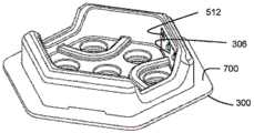
图6示出了设备220的第二示例的组件的侧视图,该设备220与用于测量生物介质中发色团浓度的改变的装置一起使用,设备220与坞300和光导布置400组装在一起。图7示出了图6的组件的VII-VII上的截面视图。如下面将进一步讨论的,在示例中,设备220可移除地被接纳在坞300中并且可连接到坞300。坞300本身可以是若干坞300中的一个,每个坞用于接纳相应的设备220并且可以被承载在某个载体上或被固定到某个载体。将参考图12讨论帽子或头饰形式的这个设备的具体示例。6 shows a side view of the components of a second example of an
这个示例中的设备220的形状/覆盖区为六边形。相应地,设备220被装配到其中的坞300形状上也是六边形的。光导布置400形状上一般也是六边形的。六边形形状是有利的,因为它使得更容易覆盖要被进行研究的特定面积或区域。在示例中,设备220的每个六边形的边是14mm。较小的尺寸是优选的,因为它使得更多的设备220能够被用于覆盖特定面积或区域,这使得成像的分辨率更大。The shape/footprint of the
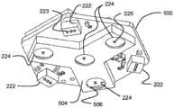
如图10B中最清楚地示出的,设备220具有至少一个光源单元222和至少一个光检测器单元224。在所示的具体示例中,设备220具有三个光源单元222和四个光检测器单元224。三个光源单元222对称地布置在设备220上,在这个示例中,朝着六边形的交错角落被定位。四个光检测器单元224同样对称地被布置在设备220上,在这个示例中,三个光检测器单元朝着六边形的其它交错角落被定位,而第四个光检测器单元被定位于六边形的中心。As shown most clearly in FIG. 10B ,
每个光源单元222具有或包含用于发射光的至少一个光源223。在示例中,光源单元222具有多个光源223。在所示的具体示例中,每个光源单元222具有三个光源223。每个光源223可以发射具有波长在例如大约600nm至1000nm范围内的光。光源223可以发射具有不同波长的光。即,在示例中,每个光源单元222具有可以发射第一波长的光的第一光源223、可以发射第二波长的光的第二光源223、以及可以发射第三波长的光的第三光源223,每个波长都不同。在示例中,该三个波长可以是735纳米、810纳米和850纳米。光源223可以是例如发光二极管(LED)。在示例中使用时,每个光源223被依次供电,使得至少在特定光源单元222内,一次只有一个光源223正在发射光。Each
每个光检测器单元224具有用于检测光的至少一个光检测器225,其可以是例如光电二极管。在所示的示例中,每个光检测器单元224具有单个光检测器225。光检测器225被布置为检测具有由光源223发射的波长的光。在示例中使用时,每个光检测器225连续地能够检测光。Each
在所示的示例中,光源单元222和光检测器单元224,且具体而言是包含在其中的光源223和光检测器225,被直接安装在印刷电路板(PCB)500上。直接在PCB 500上安装光源单元222和光检测器单元224,且具体而言是包含在其中的光源223和光检测器225,的优点是它避免了从PCB到光源223和光检测器225的(相对)长的连接电线,这因此降低了噪声和干扰。光检测器单元224靠近它们各自的放大器电路布置在PCB上,这再次有助于抑制在设备220中产生的噪声。(以上关于第一示例讨论了用于放大器电路的布置的示例。)In the example shown, the
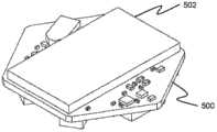
法拉第笼封住光检测器单元224及其放大器电路(因此,在这个示例的附图中,放大器电路不可见)。法拉第笼由两个主要部分组成,在PCB 500顶部的第一部分502和在PCB500底部的第二部分504。在示例中,法拉第笼可以由涂有薄锡层的铜制成。检测器单元224和它们各自的放大器电路一起与法拉第笼502、504的紧密接近提供了低噪声检测系统,其最大化了设备220的信噪比。如上面所提到的,信号强度常常非常低,而噪声水平可能非常高,而因此增加设备220的信噪比是非常重要的。A Faraday cage encloses the
在示例中,PCB 500下侧上的法拉第笼部分504具有孔506,其可以在制造期间被切入部分502中,以允许光到达检测器单元224。在一个示例中,这些孔506的入口被覆盖有一层材料,该材料对于所使用的光是透明的并且是导电的,以维持法拉第笼502、504的完整性,同时仍允许光到达检测器单元224。合适材料的示例是氧化铟锡。In an example,
在示例中,PCB 500具有若干导电垫(未示出),其使得能够连接到若干“弹簧高跷(pogo)目标”510,“弹簧高跷目标”510又使得能够连接到被安装在合适的坞系统(dockingsystem)(诸如下面进一步讨论的坞300)上的若干“弹簧高跷插针”512。(如已知的,“弹簧高跷插针”是在电子仪器中用于在两个印刷电路板、设备等之间建立(通常是临时的)连接的设备。弹簧高跷插针通常是细长圆柱形式,包含两个尖锐的、弹簧加载的插针。)为每个弹簧高跷目标510提供了弹簧连接器516。这个示例中的弹簧连接器516在其下侧焊接到PCB 500上的导电垫,上弹簧部分提供与弹簧高跷目标510的电连接。这种坞系统为PCB 500提供机械和电气连接两者。在所示的示例中,在坞300上有六个弹簧高跷插针512,其与设备220上的六个弹簧高跷目标510对应,每个弹簧高跷目标510分别在坞300和设备220的相对侧上被布置成两组,每组三个。在示例中,一组三个弹簧高跷插针512和弹簧高跷目标516分别提供电源、时钟和ID(标识)连接。ID连接可以连接到下面讨论的坞300的(柔性)PCB 310上的集成电路或芯片,ID连接为每个坞300提供用于寻址目的的其自己的唯一ID。在示例中,另一组三个弹簧高跷插针512和弹簧目标516分别为地和为形成差分总线的总线1和总线2提供,如例如在RS 485总线中所使用的。In an example, the
现在特别参考图9中的设备220的分解视图,在示例中,遮光层(black-out layer)518被附接到PCB 500的底表面。遮光层518具有用于法拉第笼的第二部分504的中央切口(cut-out)520和用于光源单元222的三个外围切口522。遮光层518防止光直接从光源单元222行进到设备220内的检测器单元224。在示例中,遮光层518由硅酮制成。Referring now specifically to the exploded view of
PCB 500和遮光层518被封在设备220的两部分壳体528、530中。壳体部分528、530可以例如由ABS制成。两个壳体部分528、530可以例如是推入配合或可以被夹在一起。顶部壳体部分528包含弹簧高跷目标机构,包括弹簧高跷目标510和弹簧连接器516。The
在示例中,底部壳体部分530包含带通干涉滤光器532,每个光检测器单元224一个带通干涉滤光器532并位于相应的光检测器单元224下方,其允许在由光源单元222发射的范围内的光通过。在具体示例中,用于光检测器单元224的带通干涉滤光器532使700至900纳米范围内的近红外光通过。在示例中,用于光检测器单元224的带通干涉滤光器532由玻璃制成。例如薄普通玻璃层的透明盖子534位于每个光源单元222下方。底部壳体部分530具有用于每个光源单元222和每个光检测器单元224的孔536,以允许光离开和进入壳体。带通干涉滤光器532和盖子534具有与它们覆盖和/或填充的底部壳体部分530中的孔536类似的尺寸和形状。In an example, the
现在参考图11,这个图示出了上面简要讨论的坞300的示例的分解视图。坞300可移除地接纳设备220并且充当设备220的机械支撑和保持器。坞300和设备220可以是摩擦配合或搭扣配合、具有脊和凹部,等等。这个示例中的坞300还为设备220提供电力和数据连接。Referring now to FIG. 11 , this figure shows an exploded view of the
坞300一般是具有直立壁302的开口容器或接受器的形式,并且设备220可以进入该容器或接受器。坞300的两个相对侧304是敞开的,这允许用户在需要时抓住设备220以从坞300移除设备220。
在这个示例中,经由设备220的弹簧高跷目标510提供与设备220的数据和电力连接的坞300的弹簧高跷插针512由两个弹簧高跷插针板306携带,每个弹簧高跷插针板携带三个弹簧高跷插针512。弹簧高跷插针板306部分地被接纳在面向内的凹部308中并由其保持,凹部308在坞300的相对着的壁302中提供。弹簧高跷插针512面向内,以便在设备220被插入坞300时与设备220的弹簧高跷目标510接合。在示例中,(柔性)PCB 310被附接到坞300的下侧。PCB310在主串行总线和连接到设备220的六个弹簧高跷插针512之间提供电连接。如上面所提到的,它还经由被安装在具有存储在其板载存储器中的唯一ID的PCB 310上的合适的集成电路或芯片提供单独识别每个坞300。主串行总线可以连接到图11中所示的PCB310的前和后凸出部。In this example, pogo pins 512 of
在示例中,坞300的基础壁312的内表面具有直立的脊314,其有助于防止光在被接纳在坞300中的设备220的光源单元222和光检测器单元224之间直接行进。在所示的示例中,存在三个脊314,当设备220被接纳在坞300中时,围绕光源单元222所在的每个区域一个脊。基础壁312还具有七个通孔316,设备220的每个光源单元222和光检测器单元224一个通孔,并且允许光导布置400被卡入到位。In an example, the inner surface of
特别参考图8C,光导布置400包括七个短长度的光导402,其形式为光纤402,设备220的每个光源单元222和光检测器单元224一个光导,在一般为平面片材404中被支撑并通过平面片材404。平面片材404可以由例如压缩模塑硅酮制成。这些光导402将来自光源单元222的光导引到被调查的组织并从该组织返回到光检测器单元224。With particular reference to FIG. 8C , the
类似于上面参考图4描述的示例,这个示例中的每个光导402具有内芯和至少一个涂层或包层。在具体示例中,光导402具有例如(聚(甲基丙烯酸甲酯)或PMMA)的内芯。内芯具有较低折射率的包层,由聚四氟乙烯(PTFE)制成。这有助于在内芯中包含光。外涂层是不透明介质,以防止光从光导402外部进入光导。外涂层还防止光从光导402内部透射到光导402的外部。外涂层可以由例如与黑色或基本上深色的颜料混合的透明硅酮形成,以提供不透明表面。黑色颜料可以是例如木炭粉末。在另一个示例中,外涂层可以由诸如PC/ABS之类的材料形成,其是聚碳酸酯和丙烯腈-丁二烯-苯乙烯的混合物。外涂层可以可替代地由诸如聚丙烯或氟化高聚物之类的材料形成。Similar to the example described above with reference to Figure 4, each
图11还示出了保持构件或片材700的一部分,其可以是柔性片材,诸如织物。保持片材700具有与光源单元222和光检测器单元224对应的若干孔702。图11还示出了用于将在下面进一步讨论的坞300的背板800。Figure 11 also shows a portion of a retaining member or
在示例中,设备220被推入配合到坞300中。坞300上的弹簧高跷插针512与设备200上的弹簧高跷目标510和弹簧连接器516之间的连接可以被用于为坞300中的设备220提供安全的连接。光导布置400从保持片材700的下侧被推入配合到坞300的主体中。一些或所有光导402的最上部分406可以向外张开或者是截头锥形等,以便与坞300的基础壁312的通孔316周围的相应形状的部分接合,从而保持光导布置400与坞300紧密接合。In an example,
图12示出了用于装配到动物身体上以测量动物身体内发色团浓度的改变的测量布置900的一部分的示例。这个示例是要被戴在受验者的头上的帽子或头饰的形式。其它构造和布置是可能的。例如,测量布置900可以是套管的形式,用于装配在肢体上,或者是更简单的片材,用于放置或包裹在某个其它身体部位周围。Figure 12 shows an example of a portion of a
测量布置900具有片状部分700。(其一部分与上面参考图11讨论的保持构件或片材700对应。)片状部分700可以方便地是柔性的、可拉伸的织物。示例是氯丁橡胶。The measuring
用于接纳设备200的若干坞300被布置在片状构件700上。坞300位于与一个(或多个)待研究区域对应的位置。在该示例中,坞300被布置为覆盖(人)受验者的整个皮质。在这个示例中,每个坞300通过首先将背板800保持在片状构件700的内部上而被固定到片状构件700。如图11中最清楚地所示,背板800具有若干直立突起或插针802,其穿过片状构件700。对应的孔704可以在片状构件700中被提供,以接纳插针802。此外,与光导402对应的孔706也可以在片状构件700中被提供。然后将坞300从片状构件700的外部向上推靠相应的背板800。背板800的插针802被接纳并且以例如卡扣连接锁定在坞300中提供的凹部中。然后,用于每个设备220的光导布置400从片状构件700的下侧被推入配合到坞300的主体中,光导402自身穿过背板800中的对应孔804。
在所示的示例中,充当总线的多导体电缆910依次将每个坞300连接到下一个坞300。这允许在使用中被接纳在坞300中的所有设备220从单个电气总线或电缆910被控制。这意味着成像阵列中所需的电气布线量被大大减少,从而再次提高了信噪比。不过,如上面所讨论的,用于到设备220和在设备220之间的数据和电力连接的其它布置是可能的。电缆910可以例如位于片状构件700的材料的顶部上或夹在片状构件700的两层之间。In the example shown, a
可以注意到的是,并非所有的坞300都必须填充有设备220。而且,填充有设备220的坞300的构造可以在调查期间可选地在运行中变化,以改变可以获得的图像和图像的性质。It may be noted that not all
因此,这种布置提供了灵活且对于任何研究的受验者(合理地)舒适的测量布置900。可以使用大量设备220,这一般而言改善了可以获得的测量和图像的深度和质量。可以容易且快速地改变设备220的布置。用于每个设备220的光导布置400可以容易地被移除,例如用于或者在特定受验者身上使用期间或者在用于不同受验者之前进行清洁,和/或更换。Thus, this arrangement provides a
在示例中,电串行总线多导体电缆910端接在“干(stem)”模块中,该“干”模块位于测量布置900的后部。这种干模块可以包含将用于设备220的总线(其可以是例如RS 485总线)转换成USB总线的电路,这使得能够将由测量布置900提供的成像阵列简单地连接到合适的膝上型PC,该膝上型PC为整个成像阵列提供电力、控制和数据收集。In an example, the electrical serial
在另一个示例中,到测量布置900的连接模块被称为“集线器”并且提供比“干”模块更多的功能。(上面关于图1中概述的示例讨论了类似的基础单元或集线器160。)这种集线器可以包含电池以向测量布置900提供电力。在一个示例中,集线器再次在(RS 485)总线900和合适的无线链路(图1中的180)之间提供总线转换,该无线链路又连接到膝上型PC等(图1中的170)。在示例中,集线器还可以包含用于成像数据的本地存储的SD卡。集线器可以具有用户界面,其由例如按钮和LED组成,以实现用户控制和基本功能的监视。在示例中,集线器还可以具有USB端口以允许系线操作(tethered operation),以及电源插座允许连续操作而不依靠电池电力。In another example, the connection modules to the
还可以提供一种光导,与用于使用至少一个光源和至少一个光检测器测量生物介质中发色团浓度的改变的装置一起使用,该光导包括:There may also be provided a light guide for use with an apparatus for measuring changes in chromophore concentration in a biological medium using at least one light source and at least one light detector, the light guide comprising:
内芯;Inner core;
内涂层,包围内芯;以及an inner coating surrounding the inner core; and
外涂层,包围内涂层;其中:An outer coating, surrounding an inner coating; of which:
内芯是对由装置的光源发射的光透明的聚合物,The inner core is a polymer transparent to the light emitted by the device's light source,
内涂层对于由装置的光源发射的光透射的光是反射的,以及the inner coating is reflective to light transmitted by light emitted by the light source of the device, and
外涂层对于从光导的内芯和内涂层射出的光是不透明的。在示例中,内芯是光学透明的硅酮。The outer coating is opaque to light exiting the inner core and inner coating of the light guide. In an example, the inner core is optically clear silicone.
应该理解的是,关于任何一个实施例描述的任何特征可以单独使用,或者与所描述的其它特征组合使用,并且还可以与任何其它实施例的一个或多个特征或者任何其它实施例的任何组合组合使用。此外,在不脱离由所附权利要求限定的本发明的范围的情况下,也可以采用上面未描述的等同物和修改。It should be understood that any feature described in relation to any one embodiment may be used alone or in combination with other features described and also in any combination with one or more features of any other embodiment or any other embodiment Use in combination. Furthermore, equivalents and modifications not described above may also be employed without departing from the scope of the present invention, which is defined by the appended claims.
Claims (24)
Priority Applications (1)
| Application Number | Priority Date | Filing Date | Title |
|---|---|---|---|
| CN202310104787.5ACN116098616A (en) | 2016-08-19 | 2017-08-18 | Measuring device and apparatus for measuring changes in chromophore concentration |
Applications Claiming Priority (3)
| Application Number | Priority Date | Filing Date | Title |
|---|---|---|---|
| GBGB1614188.9AGB201614188D0 (en) | 2016-08-19 | 2016-08-19 | Devices and apparatus for measuring changes in chromophore concetration and light guide for use therewith |
| GB1614188.9 | 2016-08-19 | ||
| PCT/GB2017/052451WO2018033751A1 (en) | 2016-08-19 | 2017-08-18 | Measuring apparatus and device for measuring changes in chromophore concentration |
Related Child Applications (1)
| Application Number | Title | Priority Date | Filing Date |
|---|---|---|---|
| CN202310104787.5ADivisionCN116098616A (en) | 2016-08-19 | 2017-08-18 | Measuring device and apparatus for measuring changes in chromophore concentration |
Publications (2)
| Publication Number | Publication Date |
|---|---|
| CN109843154A CN109843154A (en) | 2019-06-04 |
| CN109843154Btrue CN109843154B (en) | 2023-03-24 |
Family
ID=57045644
Family Applications (2)
| Application Number | Title | Priority Date | Filing Date |
|---|---|---|---|
| CN201780064317.3AActiveCN109843154B (en) | 2016-08-19 | 2017-08-18 | Measuring device and apparatus for measuring changes in chromophore concentration |
| CN202310104787.5APendingCN116098616A (en) | 2016-08-19 | 2017-08-18 | Measuring device and apparatus for measuring changes in chromophore concentration |
Family Applications After (1)
| Application Number | Title | Priority Date | Filing Date |
|---|---|---|---|
| CN202310104787.5APendingCN116098616A (en) | 2016-08-19 | 2017-08-18 | Measuring device and apparatus for measuring changes in chromophore concentration |
Country Status (6)
| Country | Link |
|---|---|
| US (3) | US20190175068A1 (en) |
| EP (2) | EP3493730B1 (en) |
| CN (2) | CN109843154B (en) |
| ES (1) | ES3035751T3 (en) |
| GB (1) | GB201614188D0 (en) |
| WO (1) | WO2018033751A1 (en) |
Cited By (1)
| Publication number | Priority date | Publication date | Assignee | Title |
|---|---|---|---|---|
| RU222921U1 (en)* | 2023-09-29 | 2024-01-23 | Общество С Ограниченной Ответственностью "Нейри" | EEG ANALYSIS MODULE BUILT INTO STEREO HEADSET |
Families Citing this family (48)
| Publication number | Priority date | Publication date | Assignee | Title |
|---|---|---|---|---|
| KR102446172B1 (en)* | 2017-10-27 | 2022-09-23 | 삼성전자주식회사 | Method for performing communication through input/output interface and apparatus therefor |
| US10158038B1 (en)* | 2018-05-17 | 2018-12-18 | Hi Llc | Fast-gated photodetector architectures comprising dual voltage sources with a switch configuration |
| WO2019221784A1 (en) | 2018-05-17 | 2019-11-21 | Hi Llc | Non-invasive wearable brain interface systems |
| US10340408B1 (en) | 2018-05-17 | 2019-07-02 | Hi Llc | Non-invasive wearable brain interface systems including a headgear and a plurality of self-contained photodetector units configured to removably attach to the headgear |
| US10420498B1 (en) | 2018-06-20 | 2019-09-24 | Hi Llc | Spatial and temporal-based diffusive correlation spectroscopy systems and methods |
| US11213206B2 (en) | 2018-07-17 | 2022-01-04 | Hi Llc | Non-invasive measurement systems with single-photon counting camera |
| WO2020131148A1 (en) | 2018-12-21 | 2020-06-25 | Hi Llc | Biofeedback for awareness and modulation of mental state using a non-invasive brain interface system and method |
| JP7539926B2 (en) | 2019-05-06 | 2024-08-26 | エイチアイ エルエルシー | Photodetector architecture for time-correlated single-photon counting |
| WO2020236371A1 (en) | 2019-05-21 | 2020-11-26 | Hi Llc | Photodetector architectures for efficient fast-gating |
| US10868207B1 (en) | 2019-06-06 | 2020-12-15 | Hi Llc | Photodetector systems with low-power time-to-digital converter architectures to determine an arrival time of photon at a photodetector based on event detection time window |
| US12144653B2 (en) | 2020-02-21 | 2024-11-19 | Hi Llc | Systems, circuits, and methods for reducing common-mode noise in biopotential recordings |
| US11630310B2 (en) | 2020-02-21 | 2023-04-18 | Hi Llc | Wearable devices and wearable assemblies with adjustable positioning for use in an optical measurement system |
| US11969259B2 (en) | 2020-02-21 | 2024-04-30 | Hi Llc | Detector assemblies for a wearable module of an optical measurement system and including spring-loaded light-receiving members |
| US11950879B2 (en) | 2020-02-21 | 2024-04-09 | Hi Llc | Estimation of source-detector separation in an optical measurement system |
| US11771362B2 (en) | 2020-02-21 | 2023-10-03 | Hi Llc | Integrated detector assemblies for a wearable module of an optical measurement system |
| US12029558B2 (en) | 2020-02-21 | 2024-07-09 | Hi Llc | Time domain-based optical measurement systems and methods configured to measure absolute properties of tissue |
| WO2021167890A1 (en)* | 2020-02-21 | 2021-08-26 | Hi Llc | Wearable module assemblies for an optical measurement system |
| US11883181B2 (en) | 2020-02-21 | 2024-01-30 | Hi Llc | Multimodal wearable measurement systems and methods |
| WO2021167876A1 (en) | 2020-02-21 | 2021-08-26 | Hi Llc | Methods and systems for initiating and conducting a customized computer-enabled brain research study |
| US12085789B2 (en) | 2020-03-20 | 2024-09-10 | Hi Llc | Bias voltage generation in an optical measurement system |
| US11245404B2 (en) | 2020-03-20 | 2022-02-08 | Hi Llc | Phase lock loop circuit based signal generation in an optical measurement system |
| US11864867B2 (en) | 2020-03-20 | 2024-01-09 | Hi Llc | Control circuit for a light source in an optical measurement system by applying voltage with a first polarity to start an emission of a light pulse and applying voltage with a second polarity to stop the emission of the light pulse |
| US11877825B2 (en) | 2020-03-20 | 2024-01-23 | Hi Llc | Device enumeration in an optical measurement system |
| WO2021188496A1 (en) | 2020-03-20 | 2021-09-23 | Hi Llc | Photodetector calibration of an optical measurement system |
| US11857348B2 (en) | 2020-03-20 | 2024-01-02 | Hi Llc | Techniques for determining a timing uncertainty of a component of an optical measurement system |
| WO2021188489A1 (en) | 2020-03-20 | 2021-09-23 | Hi Llc | High density optical measurement systems with minimal number of light sources |
| WO2021188487A1 (en) | 2020-03-20 | 2021-09-23 | Hi Llc | Temporal resolution control for temporal point spread function generation in an optical measurement system |
| US11819311B2 (en) | 2020-03-20 | 2023-11-21 | Hi Llc | Maintaining consistent photodetector sensitivity in an optical measurement system |
| US12059262B2 (en) | 2020-03-20 | 2024-08-13 | Hi Llc | Maintaining consistent photodetector sensitivity in an optical measurement system |
| US12138068B2 (en) | 2020-03-20 | 2024-11-12 | Hi Llc | Techniques for characterizing a nonlinearity of a time-to-digital converter in an optical measurement system |
| US11645483B2 (en) | 2020-03-20 | 2023-05-09 | Hi Llc | Phase lock loop circuit based adjustment of a measurement time window in an optical measurement system |
| US20210290066A1 (en)* | 2020-03-20 | 2021-09-23 | Hi Llc | Dynamic Range Optimization in an Optical Measurement System |
| US12059270B2 (en) | 2020-04-24 | 2024-08-13 | Hi Llc | Systems and methods for noise removal in an optical measurement system |
| US11941857B2 (en) | 2020-05-26 | 2024-03-26 | Hi Llc | Systems and methods for data representation in an optical measurement system |
| WO2022035626A1 (en) | 2020-08-11 | 2022-02-17 | Hi Llc | Maintaining consistent photodetector sensitivity in an optical measurement system |
| US11789533B2 (en) | 2020-09-22 | 2023-10-17 | Hi Llc | Synchronization between brain interface system and extended reality system |
| WO2022150155A1 (en) | 2021-01-06 | 2022-07-14 | Hi Llc | Devices, systems, and methods using wearable time domain-based activity tracker |
| US12433517B2 (en) | 2021-02-19 | 2025-10-07 | Hi Llc | Devices, systems, and methods for calibrating an optical measurement device |
| US20220277852A1 (en)* | 2021-02-26 | 2022-09-01 | Hi Llc | Optimizing autonomous self using non-invasive measurement systems and methods |
| US20230195228A1 (en)* | 2021-02-26 | 2023-06-22 | Hi Llc | Modular Optical-based Brain Interface System |
| US11612808B2 (en) | 2021-02-26 | 2023-03-28 | Hi Llc | Brain activity tracking during electronic gaming |
| US11543885B2 (en) | 2021-05-26 | 2023-01-03 | Hi Llc | Graphical emotion symbol determination based on brain measurement data for use during an electronic messaging session |
| US12235154B2 (en) | 2021-06-15 | 2025-02-25 | Hi Llc | Maintaining consistent photodetector sensitivity in an optical measurement system |
| US12078531B2 (en) | 2021-07-28 | 2024-09-03 | Hi Llc | Devices, systems, and methods for calibrating an optical measurement device |
| GB202204719D0 (en)* | 2022-03-31 | 2022-05-18 | Gowerlabs Ltd | Light guide module and apparatus for measuring changes in chromophore concentration |
| CN120392054A (en)* | 2022-06-21 | 2025-08-01 | 荣耀终端股份有限公司 | PPG module, PPG signal measurement method and electronic equipment |
| WO2024011174A2 (en)* | 2022-07-06 | 2024-01-11 | The General Hospital Corporation | Systems for electroencephalography and methods for use and manufacture of the same |
| EP4491102A1 (en)* | 2023-07-14 | 2025-01-15 | Universität Zürich | Monitoring device for monitoring oxygenation of cerebral tissue |
Citations (2)
| Publication number | Priority date | Publication date | Assignee | Title |
|---|---|---|---|---|
| CN101484065A (en)* | 2006-04-11 | 2009-07-15 | 诺丁汉大学 | Photoplethysmography |
| WO2011070357A1 (en)* | 2009-12-08 | 2011-06-16 | Moor Instruments Ltd | Apparatus for measuring blood parameters |
Family Cites Families (20)
| Publication number | Priority date | Publication date | Assignee | Title |
|---|---|---|---|---|
| US6163715A (en)* | 1996-07-17 | 2000-12-19 | Criticare Systems, Inc. | Direct to digital oximeter and method for calculating oxygenation levels |
| US6748254B2 (en)* | 2001-10-12 | 2004-06-08 | Nellcor Puritan Bennett Incorporated | Stacked adhesive optical sensor |
| US8328420B2 (en)* | 2003-04-22 | 2012-12-11 | Marcio Marc Abreu | Apparatus and method for measuring biologic parameters |
| FR2858758B1 (en)* | 2003-08-14 | 2006-04-07 | Tam Telesante Sarl | MEDICAL MONITORING SYSTEM USING A CLOTHING |
| WO2006109072A2 (en)* | 2005-04-14 | 2006-10-19 | Hidalgo Limited | Apparatus and system for monitoring |
| JP4991468B2 (en)* | 2007-09-28 | 2012-08-01 | 株式会社日立製作所 | Probe device |
| WO2009112281A1 (en)* | 2008-03-14 | 2009-09-17 | Eth Zurich | Garment integrated apparatus for online posture and body movement detection, analysis and feedback |
| US9549585B2 (en)* | 2008-06-13 | 2017-01-24 | Nike, Inc. | Footwear having sensor system |
| WO2010039864A2 (en)* | 2008-09-30 | 2010-04-08 | Drexel University | Functional near-infrared spectroscopy as a monitor for depth of anesthesia |
| US20100217100A1 (en)* | 2009-02-25 | 2010-08-26 | Leboeuf Steven Francis | Methods and Apparatus for Measuring Physiological Conditions |
| US8583565B2 (en)* | 2009-08-03 | 2013-11-12 | Colorado Seminary, Which Owns And Operates The University Of Denver | Brain imaging system and methods for direct prosthesis control |
| US8578082B2 (en)* | 2010-07-29 | 2013-11-05 | Covidien LLP | Configurable patient monitoring system |
| US20120035426A1 (en)* | 2010-08-03 | 2012-02-09 | Mielcarz Craig D | Extended range physiological monitoring system |
| US20120089369A1 (en)* | 2010-10-07 | 2012-04-12 | Patrick Abuzeni | Medical sensor data manager |
| US20140276014A1 (en)* | 2013-03-13 | 2014-09-18 | Cephalogics, LLC | Supports for optical sensors and related apparatus and methods |
| US20140275888A1 (en)* | 2013-03-15 | 2014-09-18 | Venture Gain LLC | Wearable Wireless Multisensor Health Monitor with Head Photoplethysmograph |
| US9615794B2 (en)* | 2013-12-03 | 2017-04-11 | Qualcomm Incorporated | Method, devices and systems for sensor with removable nodes |
| US20150327777A1 (en)* | 2014-05-14 | 2015-11-19 | Stryker Corporation | Tissue monitoring apparatus and system |
| JP6220065B2 (en)* | 2014-06-23 | 2017-10-25 | 株式会社日立製作所 | Biological light measurement device and method |
| CN204181624U (en)* | 2014-09-18 | 2015-03-04 | 中国科学院自动化研究所 | The helmet of photoelectric synchronous cerebral function imaging instrument and use thereof |
- 2016
- 2016-08-19GBGBGB1614188.9Apatent/GB201614188D0/ennot_activeCeased
- 2017
- 2017-08-18EPEP17758259.0Apatent/EP3493730B1/enactiveActive
- 2017-08-18CNCN201780064317.3Apatent/CN109843154B/enactiveActive
- 2017-08-18WOPCT/GB2017/052451patent/WO2018033751A1/ennot_activeCeased
- 2017-08-18CNCN202310104787.5Apatent/CN116098616A/enactivePending
- 2017-08-18USUS16/325,563patent/US20190175068A1/ennot_activeAbandoned
- 2017-08-18EPEP22162249.1Apatent/EP4039178B1/enactiveActive
- 2017-08-18ESES22162249Tpatent/ES3035751T3/enactiveActive
- 2021
- 2021-07-26USUS17/385,247patent/US20210345909A1/ennot_activeAbandoned
- 2023
- 2023-12-11USUS18/535,456patent/US20240108244A1/enactivePending
Patent Citations (2)
| Publication number | Priority date | Publication date | Assignee | Title |
|---|---|---|---|---|
| CN101484065A (en)* | 2006-04-11 | 2009-07-15 | 诺丁汉大学 | Photoplethysmography |
| WO2011070357A1 (en)* | 2009-12-08 | 2011-06-16 | Moor Instruments Ltd | Apparatus for measuring blood parameters |
Cited By (1)
| Publication number | Priority date | Publication date | Assignee | Title |
|---|---|---|---|---|
| RU222921U1 (en)* | 2023-09-29 | 2024-01-23 | Общество С Ограниченной Ответственностью "Нейри" | EEG ANALYSIS MODULE BUILT INTO STEREO HEADSET |
Also Published As
| Publication number | Publication date |
|---|---|
| GB201614188D0 (en) | 2016-10-05 |
| ES3035751T3 (en) | 2025-09-08 |
| CN116098616A (en) | 2023-05-12 |
| US20240108244A1 (en) | 2024-04-04 |
| EP4039178C0 (en) | 2025-04-09 |
| CN109843154A (en) | 2019-06-04 |
| EP4039178B1 (en) | 2025-04-09 |
| EP3493730A1 (en) | 2019-06-12 |
| EP3493730B1 (en) | 2022-03-16 |
| EP4039178A1 (en) | 2022-08-10 |
| WO2018033751A1 (en) | 2018-02-22 |
| US20190175068A1 (en) | 2019-06-13 |
| US20210345909A1 (en) | 2021-11-11 |
Similar Documents
| Publication | Publication Date | Title |
|---|---|---|
| CN109843154B (en) | Measuring device and apparatus for measuring changes in chromophore concentration | |
| Zhao et al. | Review of recent progress toward a fiberless, whole-scalp diffuse optical tomography system | |
| US12035996B2 (en) | High spatiotemporal resolution brain imaging | |
| US12144653B2 (en) | Systems, circuits, and methods for reducing common-mode noise in biopotential recordings | |
| Sawan et al. | Wireless recording systems: from noninvasive EEG-NIRS to invasive EEG devices | |
| US10595741B2 (en) | Method and system for brain activity detection | |
| CN109069051A (en) | The method that bio signal obtains equipment and system, acquisition bio signal | |
| Yaqub et al. | Compact, portable, high-density functional near-infrared spectroscopy system for brain imaging | |
| JP2013541990A (en) | Depth of consciousness monitor including oximeter | |
| WO2010082748A2 (en) | Form of a sensor module for measuring a photoplethysmogram for removing a motion artifact and method | |
| CN103619239A (en) | Diagnostic measuring device with built-in spectrometer | |
| CN103445774A (en) | Photoelectric electrode capable of synchronously collecting EEG signals and blood oxygen signals | |
| WO2020036246A1 (en) | Bio-signal analysis apparatus using machine learning and method therefor | |
| Mohamed et al. | Development of an integrated EEG/fNIRS brain function monitoring system | |
| CN111743515B (en) | Eight-channel diffusion correlation spectrum system for human brain function measurement | |
| JP5633464B2 (en) | Optical brain function measuring device | |
| Zimmermann et al. | Development of a wearable fNIRS system using modular electronic optodes for scalability | |
| Gagnon-Turcotte et al. | Wireless brain computer interfaces enabling synchronized optogenetics and electrophysiology | |
| Lareau et al. | Near infrared spectrometer combined with multichannel eeg for functional brain imaging | |
| CN207024055U (en) | A kind of finger cot type blood oxygen measuring device and oxygen saturation monitor system | |
| Chiarelli et al. | Wearable, fiber-less, multi-channel system for continuous wave functional near infrared spectroscopy based on silicon photomultipliers detectors and lock-in amplification | |
| Bisht et al. | TinyIOMS: a wireless miniaturised system for monitoring hemodynamics from surface brain regions | |
| CN218943319U (en) | Near infrared brain imaging device | |
| US12078531B2 (en) | Devices, systems, and methods for calibrating an optical measurement device | |
| US20240164646A1 (en) | Instrument Response Function Monitor on an Optical Measurement Device |
Legal Events
| Date | Code | Title | Description |
|---|---|---|---|
| PB01 | Publication | ||
| PB01 | Publication | ||
| SE01 | Entry into force of request for substantive examination | ||
| SE01 | Entry into force of request for substantive examination | ||
| GR01 | Patent grant | ||
| GR01 | Patent grant |