Movatterモバイル変換


[0]ホーム

URL:


CN109828689B - Touch display panel and touch display device - Google Patents

Touch display panel and touch display device
Download PDF

Info

Publication number
CN109828689B
CN109828689BCN201910100139.6ACN201910100139ACN109828689BCN 109828689 BCN109828689 BCN 109828689BCN 201910100139 ACN201910100139 ACN 201910100139ACN 109828689 BCN109828689 BCN 109828689B
Authority
CN
China
Prior art keywords
touch
area
electrodes
display panel
traces
Prior art date
Legal status (The legal status is an assumption and is not a legal conclusion. Google has not performed a legal analysis and makes no representation as to the accuracy of the status listed.)
Active
Application number
CN201910100139.6A
Other languages
Chinese (zh)
Other versions
CN109828689A (en
Inventor
杨佳瑶
黄凯泓
刘昕昭
程琳
王笑宇
王清霞
陈敏
张鹏
高转
王昊深
张启安
许孜
古赐谊
Current Assignee (The listed assignees may be inaccurate. Google has not performed a legal analysis and makes no representation or warranty as to the accuracy of the list.)
Wuhan Tianma Microelectronics Co Ltd
Original Assignee
Wuhan Tianma Microelectronics Co Ltd
Priority date (The priority date is an assumption and is not a legal conclusion. Google has not performed a legal analysis and makes no representation as to the accuracy of the date listed.)
Filing date
Publication date
Application filed by Wuhan Tianma Microelectronics Co LtdfiledCriticalWuhan Tianma Microelectronics Co Ltd
Priority to CN201910100139.6ApriorityCriticalpatent/CN109828689B/en
Publication of CN109828689ApublicationCriticalpatent/CN109828689A/en
Application grantedgrantedCritical
Publication of CN109828689BpublicationCriticalpatent/CN109828689B/en
Activelegal-statusCriticalCurrent
Anticipated expirationlegal-statusCritical

Links

Images

Landscapes

Abstract

The invention provides a touch display panel and a touch display device. A touch display panel comprises a first touch area and a bendable second touch area, wherein the first touch area comprises a first side and a second side which are opposite, and the second touch area is adjacent to the first side and/or the second side; the first touch area also comprises a plurality of first touch electrodes and a plurality of second touch electrodes which are arranged in a matrix manner; at least one first touch electrode extends to the second touch area; the second touch area further comprises a third touch electrode; in the second touch area, the first touch electrode and the third touch electrode are used for mutual capacitance touch, the first touch electrode is a touch sensing electrode and the third touch electrode is a touch driving electrode, or the first touch electrode is a touch driving electrode and the third touch electrode is a touch sensing electrode. The second touch area is arranged on the side of the touch display device, replaces a side entity key in the prior art, and is used for controlling a power supply or adjusting volume in a touch mode.

Description

Translated fromChinese
触控显示面板以及触控显示装置Touch display panel and touch display device

【技术领域】【Technical field】

本发明涉及显示技术领域,尤其涉及一种触控显示面板以及触控显示装置。The present invention relates to the field of display technology, and in particular, to a touch display panel and a touch display device.

【背景技术】【Background technique】

在现有技术中,触控显示装置采用侧边实体按键,控制电源或者调节音量。In the prior art, the touch display device uses side physical buttons to control the power supply or adjust the volume.

【发明内容】[Content of the invention]

为了解决上述技术问题,本发明提供一种触控显示面板以及触控显示装置。In order to solve the above technical problems, the present invention provides a touch display panel and a touch display device.

一方面,本发明提供一种触控显示面板,所述触控显示面板包括第一触控区、可弯折的第二触控区,所述第一触控区包括相对的第一侧、第二侧,所述第二触控区紧邻所述第一侧和/或所述第二侧;In one aspect, the present invention provides a touch display panel, the touch display panel includes a first touch area and a bendable second touch area, the first touch area includes opposite first sides, the second side, the second touch area is adjacent to the first side and/or the second side;

所述第一触控区还包括呈现矩阵排列的多个第一触控电极、多个第二触控电极;The first touch area further includes a plurality of first touch electrodes and a plurality of second touch electrodes arranged in a matrix;

其中,至少一个所述第一触控电极延伸至所述第二触控区;wherein, at least one of the first touch electrodes extends to the second touch area;

所述第二触控区还包括第三触控电极;the second touch area further includes a third touch electrode;

在所述第二触控区,所述第一触控电极与所述第三触控电极用于互容式触控,所述第一触控电极为触控感应电极并且所述第三触控电极为触控驱动电极,或者,所述第一触控电极为触控驱动电极并且所述第三触控电极为触控感应电极。In the second touch area, the first touch electrodes and the third touch electrodes are used for mutual capacitive touch, the first touch electrodes are touch sensing electrodes, and the third touch electrodes are used for mutual capacitive touch. The control electrodes are touch driving electrodes, or the first touch electrodes are touch driving electrodes and the third touch electrodes are touch sensing electrodes.

可选地,在所述第一触控区,所述第一触控电极与所述第二触控电极用于互容式触控,所述第一触控电极为触控感应电极并且所述第二触控电极为触控驱动电极,或者,所述第一触控电极为触控驱动电极并且所述第二触控电极为触控感应电极;Optionally, in the first touch area, the first touch electrodes and the second touch electrodes are used for mutual capacitive touch, and the first touch electrodes are touch sensing electrodes and all The second touch electrodes are touch drive electrodes, or the first touch electrodes are touch drive electrodes and the second touch electrodes are touch sensing electrodes;

所述第一触控区包括用于显示图像的显示层。The first touch area includes a display layer for displaying images.

可选地,所述触控显示面板还包括围绕所述第一触控区、所述第二触控区的走线区;Optionally, the touch display panel further includes a wiring area surrounding the first touch area and the second touch area;

所述走线区包括第一触控走线、第二触控走线以及第三触控走线;the wiring area includes a first touch wiring, a second touch wiring and a third touch wiring;

所述第一触控走线电连接所述第一触控电极,向其提供触控信号;the first touch traces are electrically connected to the first touch electrodes to provide touch signals to them;

所述第二触控走线电连接所述第二触控电极,向其提供触控信号;the second touch traces are electrically connected to the second touch electrodes to provide touch signals to them;

所述第三触控走线电连接所述第三触控电极,向其提供触控信号。The third touch traces are electrically connected to the third touch electrodes to provide touch signals to them.

可选地,所述触控显示面板包括至少两个紧邻所述第一侧的所述第二触控区、至少两个所述第三触控电极;Optionally, the touch display panel includes at least two second touch areas adjacent to the first side and at least two third touch electrodes;

第一个所述第二触控区与第二个所述第二触控区分离;The first second touch area is separated from the second second touch area;

第一个所述第三触控电极在第一个所述第二触控区延伸,第二个所述第三触控电极在第二个所述第二触控区延伸。The first of the third touch electrodes extends in the first of the second touch areas, and the second of the third touch electrodes extends in the second of the second touch areas.

可选地,所述触控显示面板还包括在所述走线区延伸的第一根所述第三触控走线;Optionally, the touch display panel further includes the first and third touch traces extending in the trace area;

第一根所述第三触控走线沿着所述第一侧;The first and third touch traces are along the first side;

第一根所述第三触控走线电连接第一个所述第三触控电极并且电连接第二个所述第三触控电极。The first of the third touch traces is electrically connected to the first of the third touch electrodes and is electrically connected to the second of the third touch electrodes.

可选地,所述触控显示面板还包括第三个所述第二触控区、第三个所述第三触控电极;Optionally, the touch display panel further includes the third second touch area and the third third touch electrode;

第三个所述第二触控区紧邻所述第二侧,第三个所述第三触控电极在第三个所述第二触控区延伸。The third second touch area is adjacent to the second side, and the third third touch electrode extends in the third second touch area.

可选地,所述触控显示面板还包括在所述走线区延伸的第二根所述第三触控走线;Optionally, the touch display panel further includes the second and third touch traces extending in the trace area;

第二根所述第三触控走线沿着所述第二侧;The second and third touch traces are along the second side;

第二根所述第三触控走线电连接第三个所述第三触控电极。The second third touch wire is electrically connected to the third third touch electrode.

可选地,所述第一触控区还包括第三侧,所述第三侧紧邻所述第一侧、所述第二侧;Optionally, the first touch area further includes a third side, and the third side is adjacent to the first side and the second side;

所述触控显示面板还包括在所述走线区延伸的第三根所述第三触控走线;The touch display panel further includes a third third touch trace extending in the trace area;

第三根所述第三触控走线沿着所述第一侧、所述第二侧、所述第三侧;The third third touch trace is along the first side, the second side, and the third side;

第三根所述第三触控走线电连接第一个所述第三触控电极,并且电连接第三个所述第三触控电极。The third third touch trace is electrically connected to the first third touch electrode, and is electrically connected to the third third touch electrode.

可选地,所述第一触控走线和/或所述第二触控走线与所述第一触控电极位于不同膜层,所述第一触控走线和/或第二触控走线与延伸至所述第二触控区的所述第一触控电极存在交叠。Optionally, the first touch traces and/or the second touch traces and the first touch electrodes are located in different layers, and the first touch traces and/or the second touch traces The control wirings overlap with the first touch electrodes extending to the second touch area.

可选地,所述第一触控走线和/或所述第二触控走线与所述第一触控电极位于同一膜层,所述第一触控走线和/或所述第二触控走线与延伸至所述第二触控区的所述第一触控电极不存在交叠,所述第一触控走线和/或所述第二触控走线在围绕所述第二触控区的所述走线区内延伸。Optionally, the first touch traces and/or the second touch traces and the first touch electrodes are located in the same film layer, and the first touch traces and/or the first touch traces The two touch traces do not overlap with the first touch electrodes extending to the second touch area, and the first touch traces and/or the second touch traces surround the The wiring area of the second touch area extends.

可选地,所述触控显示面板还包括偏光片,所述偏光片覆盖所述第一触控区、所述第二触控区、所述走线区。Optionally, the touch display panel further includes a polarizer, and the polarizer covers the first touch area, the second touch area, and the wiring area.

可选地,所述第二触控区包括柔性显示层,所述柔性显示层用于显示虚拟按键图像。Optionally, the second touch area includes a flexible display layer, and the flexible display layer is used to display virtual key images.

可选地,所述第二触控区为非显示区。Optionally, the second touch area is a non-display area.

可选地,所述第二触控区弯折至所述触控显示面板的侧面。Optionally, the second touch area is bent to the side of the touch display panel.

另一方面,本发明提供一种触控显示装置,所述触控显示装置包括所述触控显示面板。In another aspect, the present invention provides a touch display device including the touch display panel.

在本发明实施例中,第一触控区位于触控显示面板的正面,用于显示图像、触摸控制;其中,呈现矩阵排列的多个第一触控电极、多个第二触控电极为触控驱动电极或者触控感应电极,用于互容式触控;第二触控区紧邻第一触控区的第一侧和/或第二侧,弯折至触控显示面板的侧面,用于触摸控制,或者用于触摸控制、显示图像;其中,第一触控电极与第三触控电极为触控驱动电极或者触控感应电极,用于互容式触控。触控显示面板设置于触控显示装置中,第一触控区设置于触控显示装置的正面,第二触控区设置于触控显示装置的侧边,替代现有技术中的侧边实体按键,用于触控控制电源或者调节音量;第二触控区的触摸控制与侧边实体按键的按压控制相比,灵敏度较高。第一触控区、第二触控区都有第一触控电极,第一触控区、第二触控区中同行的第一触控电极电连接并且共同传输触控信号,避免第一触控区、第二触控区中同行的第一触控电极采用其他触控走线电连接,节省其他触控走线的空间,避免第一触控区、第二触控区中同行的第一触控电极分别传输触控信号,简化第一触控电极传输触控信号的过程。In the embodiment of the present invention, the first touch area is located on the front of the touch display panel, and is used for displaying images and touch control; wherein the plurality of first touch electrodes and the plurality of second touch electrodes arranged in a matrix are The touch driving electrodes or the touch sensing electrodes are used for mutual capacitive touch; the second touch area is adjacent to the first side and/or the second side of the first touch area, and is bent to the side of the touch display panel, It is used for touch control, or for touch control and display of images; wherein, the first touch electrodes and the third touch electrodes are touch drive electrodes or touch sensing electrodes, which are used for mutual capacitive touch. The touch display panel is arranged in the touch display device, the first touch area is arranged on the front of the touch display device, and the second touch area is arranged on the side of the touch display device, instead of the side entity in the prior art The button is used to touch the power supply or adjust the volume; the touch control of the second touch area is more sensitive than the pressing control of the side physical buttons. The first touch area and the second touch area have first touch electrodes, and the first touch electrodes in the first touch area and the second touch area are electrically connected and transmit touch signals together to avoid the first touch The first touch electrodes in the same line in the touch area and the second touch area are electrically connected by other touch traces, which saves the space of other touch traces and avoids the parallel connection in the first touch area and the second touch area. The first touch electrodes transmit touch signals respectively, which simplifies the process of transmitting the touch signals by the first touch electrodes.

【附图说明】【Description of drawings】

为了更清楚地说明本发明实施例的技术方案,下面将对实施例中所需要使用的附图作简单地介绍,显而易见地,下面描述中的附图仅仅是本发明的一些实施例,对于本领域普通技术人员来讲,在不付出创造性劳动的前提下,还可以根据这些附图获得其它的附图。In order to illustrate the technical solutions of the embodiments of the present invention more clearly, the following briefly introduces the accompanying drawings used in the embodiments. Obviously, the drawings in the following description are only some embodiments of the present invention. For those of ordinary skill in the art, other drawings can also be obtained from these drawings without any creative effort.

图1是现有技术中触控显示装置100的正视图;FIG. 1 is a front view of atouch display device 100 in the prior art;

图2是现有技术中触控显示装置100的侧视图;FIG. 2 is a side view of thetouch display device 100 in the prior art;

图3是本发明实施例中一种触控显示面板200的正视图;FIG. 3 is a front view of atouch display panel 200 according to an embodiment of the present invention;

图4是本发明实施例中另一种触控显示面板200的正视图;FIG. 4 is a front view of anothertouch display panel 200 according to an embodiment of the present invention;

图5是本发明实施例中另一种触控显示面板200的正视图;FIG. 5 is a front view of anothertouch display panel 200 according to an embodiment of the present invention;

图6是本发明实施例中另一种触控显示面板200的侧视图;FIG. 6 is a side view of anothertouch display panel 200 according to an embodiment of the present invention;

图7是本发明实施例中另一种触控显示面板200的剖视图;FIG. 7 is a cross-sectional view of anothertouch display panel 200 according to an embodiment of the present invention;

图8是本发明实施例中另一种触控显示面板200在第二触控区210B的剖视图;8 is a cross-sectional view of anothertouch display panel 200 in thesecond touch area 210B according to an embodiment of the present invention;

图9是本发明实施例中另一种触控显示面板200的正视图;FIG. 9 is a front view of anothertouch display panel 200 according to an embodiment of the present invention;

图10是本发明实施例中另一种触控显示面板200在第二触控区210B的剖视图;10 is a cross-sectional view of anothertouch display panel 200 in thesecond touch area 210B according to an embodiment of the present invention;

图11是本发明实施例中一种触控显示装置300的正视图;FIG. 11 is a front view of atouch display device 300 according to an embodiment of the present invention;

图12是本发明实施例中一种触控显示装置300的侧视图。FIG. 12 is a side view of atouch display device 300 according to an embodiment of the present invention.

【具体实施方式】【Detailed ways】

为了更好的理解本发明的技术方案,下面结合附图对本发明实施例进行详细描述。In order to better understand the technical solutions of the present invention, the embodiments of the present invention are described in detail below with reference to the accompanying drawings.

应当明确,所描述的实施例仅仅是本发明一部分实施例,而不是全部的实施例。基于本发明中的实施例,本领域普通技术人员在没有作出创造性劳动前提下所获得的所有其它实施例,都属于本发明保护的范围。It should be understood that the described embodiments are only some, but not all, embodiments of the present invention. Based on the embodiments of the present invention, all other embodiments obtained by those of ordinary skill in the art without creative efforts shall fall within the protection scope of the present invention.

在本发明实施例中使用的术语是仅仅出于描述特定实施例的目的,而非旨在限制本发明。在本发明实施例和所附权利要求书中所使用的单数形式的“一种”、“所述”和“该”也旨在包括多数形式,除非上下文清楚地表示其他含义。The terms used in the embodiments of the present invention are only for the purpose of describing specific embodiments, and are not intended to limit the present invention. As used in the embodiments of the present invention and the appended claims, the singular forms "a," "the," and "the" are intended to include the plural forms as well, unless the context clearly dictates otherwise.

应当理解,本文中使用的术语“和/或”仅仅是一种描述关联对象的关联关系,表示可以存在三种关系,例如,A和/或B,可以表示:单独存在A,同时存在A和B,单独存在B这三种情况。另外,本文中字符“/”,一般表示前后关联对象是一种“或”的关系。It should be understood that the term "and/or" used in this document is only an association relationship to describe the associated objects, indicating that there may be three kinds of relationships, for example, A and/or B, which may indicate that A exists alone, and A and B exist at the same time. B, there are three cases of B alone. In addition, the character "/" in this document generally indicates that the related objects are an "or" relationship.

应当理解,尽管在本发明实施例中可能采用术语第一、第二等来描述装置,但这些装置不应限于这些术语。这些术语仅用来将装置彼此区分开。例如,在不脱离本发明实施例范围的情况下,第一装置也可以被称为第二装置,类似地,第二装置也可以被称为第一装置。It should be understood that although the terms first, second, etc. may be used to describe devices in the embodiments of the present invention, these devices should not be limited by these terms. These terms are only used to distinguish devices from one another. For example, without departing from the scope of the embodiments of the present invention, a first device may also be referred to as a second device, and similarly, a second device may also be referred to as a first device.

图1是现有技术中触控显示装置100的正视图;图2是现有技术中触控显示装置100的侧视图。FIG. 1 is a front view of atouch display device 100 in the prior art; FIG. 2 is a side view of thetouch display device 100 in the prior art.

如图1、2所示,在现有技术中,触控显示装置100包括触控显示面板110、侧边实体按键120。触控显示面板110位于触控显示装置100的正面,用于触摸控制。侧边实体按键120位于触控显示装置100的侧面并且用于按压控制。触控显示面板110并未替代侧边实体按键120、用于控制电源或者调节音量。As shown in FIGS. 1 and 2 , in the prior art, thetouch display device 100 includes atouch display panel 110 and sidephysical buttons 120 . Thetouch display panel 110 is located on the front of thetouch display device 100 and is used for touch control. The sidephysical buttons 120 are located on the side of thetouch display device 100 and are used for pressing control. Thetouch display panel 110 does not replace the sidephysical buttons 120 for controlling the power supply or adjusting the volume.

为了解决上述技术问题,本发明提供一种触控显示面板以及触控显示装置。In order to solve the above technical problems, the present invention provides a touch display panel and a touch display device.

图3是本发明实施例中一种触控显示面板200的正视图;图4是本发明实施例中另一种触控显示面板200的正视图;图5是本发明实施例中另一种触控显示面板200的正视图;图6是本发明实施例中另一种触控显示面板200的侧视图;图7是本发明实施例中另一种触控显示面板200的剖视图。FIG. 3 is a front view of atouch display panel 200 according to an embodiment of the present invention; FIG. 4 is a front view of anothertouch display panel 200 according to an embodiment of the present invention; FIG. 5 is another embodiment of the present invention. A front view of thetouch display panel 200; FIG. 6 is a side view of anothertouch display panel 200 according to an embodiment of the present invention; FIG. 7 is a cross-sectional view of anothertouch display panel 200 according to an embodiment of the present invention.

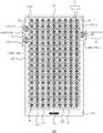
如图3至7所示,触控显示面板200包括第一触控区210A、可弯折的第二触控区210B,第一触控区210A包括相对的第一侧B1、第二侧B2,第二触控区210B紧邻第一侧B1和/或第二侧B2;第一触控区210A还包括呈现矩阵排列的多个第一触控电极211、多个第二触控电极212;其中,至少一个第一触控电极211延伸至第二触控区210B;第二触控区210B还包括第三触控电极213;在第二触控区210B,第一触控电极211与第三触控电极213用于互容式触控,第一触控电极211为触控感应电极并且第三触控电极213为触控驱动电极,或者,第一触控电极211为触控驱动电极并且第三触控电极213为触控感应电极。As shown in FIGS. 3 to 7 , thetouch display panel 200 includes afirst touch area 210A and a bendablesecond touch area 210B, and thefirst touch area 210A includes opposite first sides B1 and second sides B2 , thesecond touch area 210B is adjacent to the first side B1 and/or the second side B2; thefirst touch area 210A further includes a plurality offirst touch electrodes 211 and a plurality ofsecond touch electrodes 212 arranged in a matrix; Wherein, at least onefirst touch electrode 211 extends to thesecond touch area 210B; thesecond touch area 210B further includes athird touch electrode 213 ; in thesecond touch area 210B, thefirst touch electrode 211 and thesecond touch area 210B The threetouch electrodes 213 are used for mutual capacitive touch, thefirst touch electrodes 211 are touch sensing electrodes and thethird touch electrodes 213 are touch driving electrodes, or thefirst touch electrodes 211 are touch driving electrodes And thethird touch electrodes 213 are touch sensing electrodes.

在本发明实施例中,第一触控区210A位于触控显示面板200的正面,用于显示图像、触摸控制;其中,呈现矩阵排列的多个第一触控电极211、多个第二触控电极212为触控驱动电极或者触控感应电极,用于互容式触控;第二触控区210B紧邻第一触控区210A的第一侧B1和/或第二侧B2,弯折至触控显示面板200的侧面,用于触摸控制,或者用于触摸控制、显示图像;其中,第一触控电极211与第三触控电极213为触控驱动电极或者触控感应电极,用于互容式触控。触控显示面板200设置于触控显示装置中,第一触控区210A设置于触控显示装置的正面,第二触控区210B设置于触控显示装置的侧边,替代现有技术中的侧边实体按键,用于控制电源或者调节音量;第二触控区210B的触摸控制与侧边实体按键的按压控制相比,灵敏度较高。第一触控区210A、第二触控区210B都有第一触控电极211,第一触控区210A、第二触控区210B中同行的第一触控电极211电连接并且共同传输触控信号,避免第一触控区210A、第二触控区210B中同行的第一触控电极211采用其他触控走线电连接,节省其他触控走线的空间,避免第一触控区210A、第二触控区210B中同行的第一触控电极211分别传输触控信号,简化第一触控电极211传输触控信号的过程。In the embodiment of the present invention, thefirst touch area 210A is located on the front of thetouch display panel 200 and is used for displaying images and touch control; wherein, a plurality offirst touch electrodes 211 and a plurality of second touch electrodes arranged in a matrix are presented. Thecontrol electrodes 212 are touch driving electrodes or touch sensing electrodes for mutual capacitive touch; thesecond touch area 210B is adjacent to the first side B1 and/or the second side B2 of thefirst touch area 210A, and is bent to the side of thetouch display panel 200 for touch control, or for touch control and displaying images; wherein, thefirst touch electrodes 211 and thethird touch electrodes 213 are touch driving electrodes or touch sensing electrodes, which are used for touch control. for mutual capacitive touch. Thetouch display panel 200 is disposed in the touch display device, thefirst touch area 210A is disposed on the front of the touch display device, and thesecond touch area 210B is disposed on the side of the touch display device, which replaces the prior art. The side physical buttons are used to control the power supply or adjust the volume; the touch control of thesecond touch area 210B has higher sensitivity than the pressing control of the side physical buttons. Thefirst touch area 210A and thesecond touch area 210B havefirst touch electrodes 211 , and thefirst touch electrodes 211 in thefirst touch area 210A and thesecond touch area 210B are electrically connected to each other and transmit the touch together. control signal, avoid thefirst touch electrodes 211 in thefirst touch area 210A and thesecond touch area 210B in the same line to be electrically connected with other touch traces, save the space of other touch traces, and avoid the first touch area Thefirst touch electrodes 211 in the same row in thesecond touch areas 210A and 210B transmit touch signals respectively, which simplifies the process of transmitting the touch signals by thefirst touch electrodes 211 .

如图3至7所示,在第一触控区210A,第一触控电极211与第二触控电极212用于互容式触控,第一触控电极211为触控感应电极并且第二触控电极212为触控驱动电极,或者,第一触控电极211为触控驱动电极并且第二触控电极212为触控感应电极;第一触控区210A包括用于显示图像的显示层230A。As shown in FIGS. 3 to 7 , in thefirst touch area 210A, thefirst touch electrodes 211 and thesecond touch electrodes 212 are used for mutual capacitive touch, thefirst touch electrodes 211 are touch sensing electrodes and thefirst touch electrodes 211 are touch sensing electrodes. The twotouch electrodes 212 are touch driving electrodes, or thefirst touch electrodes 211 are touch driving electrodes and thesecond touch electrodes 212 are touch sensing electrodes; thefirst touch area 210A includes a display for displayingimages Layer 230A.

在本发明实施例中,在第一触控区210A,第一触控电极211、第二触控电极212为触控驱动电极或者触控感应电极,构成第一触控单元S1,用于互容式触控;在第二触控区210B,第一触控电极211、第三触控电极213为触控驱动电极或者触控感应电极,构成第二触控单元S2,用于互容式触控。在互容式触控中,触控显示面板200包括触控驱动电极、触控感应电极、触控芯片IC。触控驱动电极与触控感应电极之间设置绝缘介质,触控驱动电极与触控感应电极之间存在电容耦合。触控驱动电极电连接触控芯片IC,触控芯片IC对触控驱动电极传输驱动信号。由于触控驱动电极与触控感应电极之间的电容耦合,当触控驱动电极具有驱动信号时,触控感应电极具有感应信号。触控感应电极电连接触控芯片IC,触控芯片IC对触控感应电极检测感应信号。触控芯片IC根据驱动信号、感应信号确定触控驱动电极与触控感应电极之间的电容耦合。当触摸物体靠近触控驱动电极、触控感应电极时,触控驱动电极与触控感应电极之间的电容耦合变化,虽然驱动信号不变,但是感应信号变化。触控芯片IC根据驱动信号、感应信号确定触控驱动电极与触控感应电极之间的电容耦合变化,据此判断触摸物体。于是,第一触控电极211、第二触控电极212为触控驱动电极或者触控感应电极,第一触控电极211与第二触控电极212之间的电容耦合变化用于判断触摸物体;第一触控电极211、第三触控电极213为触控驱动电极或者触控感应电极,第一触控电极211与第三触控电极213之间的电容耦合变化用于判断触摸物体。In the embodiment of the present invention, in thefirst touch area 210A, thefirst touch electrodes 211 and thesecond touch electrodes 212 are touch driving electrodes or touch sensing electrodes, forming a first touch unit S1 for mutual Capacitive touch; in thesecond touch area 210B, thefirst touch electrodes 211 and thethird touch electrodes 213 are touch driving electrodes or touch sensing electrodes, forming a second touch unit S2 for mutual capacitive touch touch. In the mutual capacitive touch, thetouch display panel 200 includes touch driving electrodes, touch sensing electrodes, and a touch chip IC. An insulating medium is arranged between the touch driving electrodes and the touch sensing electrodes, and capacitive coupling exists between the touch driving electrodes and the touch sensing electrodes. The touch driving electrodes are electrically connected to the touch chip IC, and the touch chip IC transmits driving signals to the touch driving electrodes. Due to the capacitive coupling between the touch driving electrodes and the touch sensing electrodes, when the touch driving electrodes have driving signals, the touch sensing electrodes have sensing signals. The touch sensing electrodes are electrically connected to the touch chip IC, and the touch chip IC detects sensing signals to the touch sensing electrodes. The touch chip IC determines the capacitive coupling between the touch driving electrodes and the touch sensing electrodes according to the driving signal and the sensing signal. When the touch object approaches the touch driving electrodes and the touch sensing electrodes, the capacitive coupling between the touch driving electrodes and the touch sensing electrodes changes. Although the driving signal does not change, the sensing signal changes. The touch chip IC determines the capacitive coupling change between the touch driving electrodes and the touch sensing electrodes according to the driving signal and the sensing signal, and judges the touch object accordingly. Therefore, thefirst touch electrodes 211 and thesecond touch electrodes 212 are touch driving electrodes or touch sensing electrodes, and the capacitive coupling change between thefirst touch electrodes 211 and thesecond touch electrodes 212 is used to determine the touch object ; Thefirst touch electrodes 211 and thethird touch electrodes 213 are touch drive electrodes or touch sensing electrodes, and the capacitive coupling change between thefirst touch electrodes 211 and thethird touch electrodes 213 is used to determine the touch object.

在本发明实施例中,在第一触控区210A中,显示层230A包括多个有机发光材料层,例如空穴注入层、空穴传输层、发光层、电子传输层、电子注入层,多个有机发光材料层层叠设置,用于电致发光、显示图像;第一触控电极211或者第二触控电极212在显示层230A上透光。In the embodiment of the present invention, in thefirst touch area 210A, thedisplay layer 230A includes a plurality of organic light-emitting material layers, such as a hole injection layer, a hole transport layer, a light-emitting layer, an electron transport layer, an electron injection layer, etc. The organic light-emitting material layers are stacked and arranged for electroluminescence and image display; thefirst touch electrodes 211 or thesecond touch electrodes 212 transmit light on thedisplay layer 230A.

如图3至5所示,触控显示面板200还包括围绕第一触控区210A、第二触控区210B的走线区220;走线区220包括第一触控走线221、第二触控走线222以及第三触控走线223;第一触控走线221电连接第一触控电极211,向其提供触控信号;第二触控走线222电连接第二触控电极212,向其提供触控信号;第三触控走线223电连接第三触控电极213,向其提供触控信号。As shown in FIGS. 3 to 5 , thetouch display panel 200 further includes awiring area 220 surrounding thefirst touch area 210A and thesecond touch area 210B; thewiring area 220 includes thefirst touch wiring 221 , the second touch The touch traces 222 and the third touch traces 223; the first touch traces 221 are electrically connected to thefirst touch electrodes 211 to provide touch signals; the second touch traces 222 are electrically connected to the second touch electrodes Theelectrodes 212 are provided with touch signals; thethird touch wires 223 are electrically connected to thethird touch electrodes 213 and provided with touch signals.

在本发明实施例中,走线区220围绕第一触控区210A、第二触控区210B,以便走线区220中的第一触控走线221、第二触控走线222分别电连接第一触控区210A中的第一触控电极211、第二触控电极212,以便走线区220中的第三触控走线223电连接第二触控区210B中的第三触控电极213。走线区220还包括触控芯片IC,触控芯片IC电连接第一触控走线221、第二触控走线222以及第三触控走线223。触控芯片IC采用第一触控走线221对第一触控电极211传输驱动信号或者检测感应信号,采用第二触控走线222对第二触控电极212传输驱动信号或者检测感应信号,采用第三触控走线223对第三触控电极213传输驱动信号或者检测感应信号,驱动信号或者感应信号就是触控信号。In the embodiment of the present invention, thewiring area 220 surrounds thefirst touch area 210A and thesecond touch area 210B, so that thefirst touch wiring 221 and thesecond touch wiring 222 in thewiring area 220 are respectively electrically connected Thefirst touch electrodes 211 and thesecond touch electrodes 212 in thefirst touch area 210A are connected, so that the third touch traces 223 in thetrace area 220 are electrically connected to the third touch traces in thesecond touch area 210B.Control electrode 213 . Thetrace area 220 further includes a touch chip IC, and the touch chip IC is electrically connected to thefirst touch trace 221 , thesecond touch trace 222 and thethird touch trace 223 . The touch chip IC uses the first touch traces 221 to transmit drive signals or detect sensing signals to thefirst touch electrodes 211 , and uses the second touch traces 222 to transmit drive signals or detect sensing signals to thesecond touch electrodes 212 . The third touch traces 223 are used to transmit driving signals or detection sensing signals to thethird touch electrodes 213 , and the driving signals or the sensing signals are touch signals.

如图3至5所示,触控显示面板200包括至少两个紧邻第一侧B1的第二触控区210B、至少两个第三触控电极213;第一个第二触控区210B-1与第二个第二触控区210B-2分离;第一个第三触控电极213-1在第一个第二触控区210B-1延伸,第二个第三触控电极213-2在第二个第二触控区210B-2延伸。As shown in FIGS. 3 to 5 , thetouch display panel 200 includes at least twosecond touch areas 210B adjacent to the first side B1 and at least twothird touch electrodes 213 ; the firstsecond touch area 210B- 1 is separated from the secondsecond touch area 210B-2; the first third touch electrode 213-1 extends in the firstsecond touch area 210B-1, and the second third touch electrode 213- 2 extends in the secondsecond touch area 210B-2.

在本发明实施例中,两个第二触控区210B紧邻第一触控区210A的第一侧B1,弯折至触控显示面板200的侧面,用于调节音量;第一个第二触控区210B-1与第二个第二触控区210B-2分离,第一个第二触控区210B-1用于调大音量并且第二个第二触控区210B-2用于调小音量,或者,第一个第二触控区210B-1用于调小音量并且第二个第二触控区210B-2用于调大音量;在第一个第二触控区210B-1,第一个第三触控电极213-1、第一触控电极211为触控驱动电极或者触控感应电极,用于互容式触控;在第二个第二触控区210B-2,第二个第三触控电极213-2、第一触控电极211为触控驱动电极或者触控感应电极,用于互容式触控。In the embodiment of the present invention, the twosecond touch areas 210B are adjacent to the first side B1 of thefirst touch area 210A, and are bent to the side of thetouch display panel 200 for adjusting the volume; Thecontrol area 210B-1 is separated from the secondsecond touch area 210B-2, the firstsecond touch area 210B-1 is used to increase the volume and the secondsecond touch area 210B-2 is used to adjust the volume Volume down, or the firstsecond touch area 210B-1 is used to turn down the volume and the secondsecond touch area 210B-2 is used to turn up the volume; in the firstsecond touch area 210B- 1. The first third touch electrodes 213-1 and thefirst touch electrodes 211 are touch driving electrodes or touch sensing electrodes for mutual capacitive touch; in the secondsecond touch area 210B- 2. The second third touch electrode 213-2 and thefirst touch electrode 211 are touch driving electrodes or touch sensing electrodes, which are used for mutual capacitive touch.

如图3至5所示,触控显示面板200还包括在走线区220延伸的第一根第三触控走线223-1;第一根第三触控走线223-1沿着第一侧B1延伸;第一根第三触控走线223-1电连接第一个第三触控电极213-1并且电连接第二个第三触控电极213-2。As shown in FIGS. 3 to 5 , thetouch display panel 200 further includes a first third touch trace 223 - 1 extending in thetrace area 220 ; the first third touch trace 223 - 1 is along the first One side B1 extends; the first third touch wire 223-1 is electrically connected to the first third touch electrode 213-1 and is electrically connected to the second third touch electrode 213-2.

在本发明实施例中,第一根第三触控走线223-1在走线区220延伸并且沿着第一触控区210A的第一侧B1延伸,在第一触控区210A的第一侧B1,走线区220紧邻第一个第二触控区210B-1、第二个第二触控区210B-2,以便第一根第三触控走线223-1电连接走线区220中的触控芯片IC、第一个第二触控区210B-1中的第一个第三触控电极213-1、第二个第二触控区210B-2中的第二个第三触控电极213-2。触控芯片IC采用第一根第三触控走线223-1,对第一个第三触控电极213-1以及第二个第三触控电极213-2,传输驱动信号或者检测感应信号。In the embodiment of the present invention, the first third touch trace 223 - 1 extends in thetrace area 220 and extends along the first side B1 of thefirst touch area 210A. On the side B1, thetrace area 220 is adjacent to the firstsecond touch area 210B-1 and the secondsecond touch area 210B-2, so that the first third touch trace 223-1 is electrically connected to the trace The touch chip IC in thearea 220, the first third touch electrode 213-1 in the firstsecond touch area 210B-1, the second in the secondsecond touch area 210B-2 The third touch electrode 213-2. The touch chip IC adopts the first third touch trace 223-1 to transmit driving signals or detect sensing signals to the first third touch electrodes 213-1 and the second third touch electrodes 213-2 .

如图3至5所示,触控显示面板200还包括第三个第二触控区210B-3、第三个第三触控电极213-3;第三个第二触控区210B-3紧邻第二侧B2,第三个第三触控电极213-3在第三个第二触控区210B-3延伸。As shown in FIGS. 3 to 5 , thetouch display panel 200 further includes a thirdsecond touch area 210B-3, a third third touch electrode 213-3, and a thirdsecond touch area 210B-3 Adjacent to the second side B2, the third third touch electrodes 213-3 extend in the thirdsecond touch area 210B-3.

在本发明实施例中,第三个第二触控区210B-3紧邻第一触控区210A的第二侧B2,弯折至触控显示面板200的侧面,用于控制电源;在第三个第二触控区210B-3,第三个第三触控电极213-3、第一触控电极211为触控驱动电极或者触控感应电极,用于互容式触控。In the embodiment of the present invention, the thirdsecond touch area 210B-3 is adjacent to the second side B2 of thefirst touch area 210A, and is bent to the side of thetouch display panel 200 for power control; in the third Thesecond touch area 210B-3, the third third touch electrode 213-3, and thefirst touch electrode 211 are touch driving electrodes or touch sensing electrodes for mutual capacitive touch.

如图3所示,触控显示面板200还包括在走线区220延伸的第二根第三触控走线223-2;第二根第三触控走线223-2沿着第二侧B2延伸;第二根第三触控走线223-2电连接第三个第三触控电极213-3。As shown in FIG. 3 , thetouch display panel 200 further includes a second third touch trace 223 - 2 extending in thetrace area 220 ; the second third touch trace 223 - 2 is along the second side B2 extends; the second third touch wire 223-2 is electrically connected to the third third touch electrode 213-3.

在本发明实施例中,第二根第三触控走线223-2在走线区220延伸并且沿着第一触控区210A的第二侧B2延伸,在第一触控区210A的第二侧B2,走线区220紧邻第三个第二触控区210B-3,以便第二根第三触控走线223-2电连接走线区220中的触控芯片IC、第三个第二触控区210B-3中的第三个第三触控电极213-3。触控芯片IC采用第二根第三触控走线223-2,对第三个第三触控电极213-3,传输驱动信号或者检测感应信号。In the embodiment of the present invention, the second third touch trace 223 - 2 extends in thetrace area 220 and extends along the second side B2 of thefirst touch area 210A. On the two sides B2, thetrace area 220 is adjacent to the thirdsecond touch area 210B-3, so that the second third touch trace 223-2 is electrically connected to the touch chip IC and the third touch trace in thetrace area 220. The third third touch electrode 213-3 in thesecond touch area 210B-3. The touch chip IC adopts the second third touch wire 223-2 to transmit a driving signal or detect an induction signal to the third third touch electrode 213-3.

在本发明实施例中,触控芯片IC采用第一根第三触控走线223-1对第一个第三触控电极213-1以及第二个第三触控电极213-2传输驱动信号或者检测感应信号;另外,触控芯片IC采用第二根第三触控走线223-2对第三个第三触控电极213-3传输驱动信号或者检测感应信号。第一根第三触控走线223-1紧邻第一触控区210A的第一侧B1,第二根第三触控走线223-2紧邻第一触控区210A的第二侧B2,第一根第三触控走线223-1、第二根第三触控走线223-2较短;第一根第三触控走线223-1电连接第一个第三触控电极213-1、第二个第三触控电极213-2,第二根第三触控走线223-2电连接第三个第三触控电极213-3,第一根第三触控走线223-1电连接的负载、第二根第三触控走线223-2的负载非常小。于是,第一根第三触控走线223-1/第二根第三触控走线223-2本身的负载以及电连接的负载非常小,避免第一根第三触控走线223-1/第二根第三触控走线223-2的负载影响触控芯片IC传输驱动信号或者检测感应信号。In the embodiment of the present invention, the touch chip IC uses the first third touch trace 223-1 to transmit and drive the first third touch electrode 213-1 and the second third touch electrode 213-2 signal or detection sensing signal; in addition, the touch chip IC uses the second third touch trace 223-2 to transmit the driving signal or detect the sensing signal to the third third touch electrode 213-3. The first third touch wire 223-1 is adjacent to the first side B1 of thefirst touch area 210A, and the second third touch wire 223-2 is adjacent to the second side B2 of thefirst touch area 210A. The first third touch trace 223-1 and the second third touch trace 223-2 are shorter; the first third touch trace 223-1 is electrically connected to the first third touch electrode 213-1, the second third touch electrode 213-2, the second third touch trace 223-2 is electrically connected to the third third touch electrode 213-3, the first third touch trace The load electrically connected to the line 223-1 and the load of the second third touch trace 223-2 are very small. Therefore, the load of the first third touch trace 223-1/the second third touch trace 223-2 itself and the load of the electrical connection are very small, avoiding the first third touch trace 223-2- 1/ The load of the second third touch trace 223-2 affects the touch chip IC to transmit driving signals or detect sensing signals.

如图4所示,第一触控区210A还包括第三侧B3,第三侧B3紧邻第一侧B1、第二侧B2;触控显示面板200还包括在走线区220延伸的第三根第三触控走线223-3;第三根第三触控走线223-3沿着第一侧B1、第二侧B2、第三侧B3延伸;第三根第三触控走线223-3电连接第一个第三触控电极213-1,并且电连接第三个第三触控电极213-3。As shown in FIG. 4 , thefirst touch area 210A further includes a third side B3 , and the third side B3 is adjacent to the first side B1 and the second side B2 ; thetouch display panel 200 further includes a third side extending in thewiring area 220 . A third touch trace 223-3; the third third touch trace 223-3 extends along the first side B1, the second side B2, and the third side B3; the third third touch trace 223-3 is electrically connected to the first third touch electrode 213-1, and is electrically connected to the third third touch electrode 213-3.

在本发明实施例中,第三根第三触控走线223-3在走线区220延伸并且沿着第一触控区210A的第一侧B1、第二侧B2、第三侧B3延伸,在第一触控区210A的第一侧B1、第三侧B3,走线区220紧邻第一个第二触控区210B-1、第三个第二触控区210B-3,以便第三根第三触控走线223-3电连接第一个第二触控区210B-1中的第一个第三触控电极213-1、第三个第二触控区210B-3中的第三个第三触控电极213-3。同时,第一根第三触控走线223-1电连接触控芯片IC、第一个第三触控电极213-1、第二个第三触控电极213-2。触控芯片IC采用第一根第三触控走线223-1以及第三根第三触控走线223-3,对第一个第三触控电极213-1、第二个第三触控电极213-2以及第三个第三触控电极213-3,传输驱动信号或者检测感应信号。触控芯片IC对第一个第三触控电极213-1、第二个第三触控电极213-2以及第三个第三触控电极213-3,一并传输驱动信号或者检测感应信号,避免触控芯片IC分别传输驱动信号或者检测感应信号并且简化触控芯片IC传输驱动信号或者检测感应信号的过程。In the embodiment of the present invention, the third third touch trace 223 - 3 extends in thetrace area 220 and extends along the first side B1 , the second side B2 and the third side B3 of thefirst touch area 210A , on the first side B1 and the third side B3 of thefirst touch area 210A, thewiring area 220 is adjacent to the firstsecond touch area 210B-1 and the thirdsecond touch area 210B-3, so that the first The three third touch traces 223-3 are electrically connected to the first third touch electrodes 213-1 in the firstsecond touch area 210B-1 and the thirdsecond touch area 210B-3 The third third touch electrode 213-3. Meanwhile, the first third touch trace 223-1 is electrically connected to the touch chip IC, the first third touch electrode 213-1, and the second third touch electrode 213-2. The touch chip IC adopts the first third touch wire 223-1 and the third third touch wire 223-3 to connect the first third touch electrode 213-1 and the second third touch wire 213-1 to the second third touch wire. The control electrodes 213-2 and the third third touch electrodes 213-3 transmit driving signals or detect sensing signals. The touch chip IC transmits a driving signal or detects a sensing signal to the first third touch electrode 213-1, the second third touch electrode 213-2 and the third third touch electrode 213-3. , to avoid the touch chip IC from respectively transmitting the driving signal or detecting the sensing signal and simplify the process of the touch chip IC transmitting the driving signal or detecting the sensing signal.

图8是本发明实施例中另一种触控显示面板200在第二触控区210B的剖视图。8 is a cross-sectional view of anothertouch display panel 200 in thesecond touch area 210B according to an embodiment of the present invention.

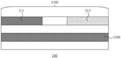
如图3、8所示,第一触控走线221和/或第二触控走线222与第一触控电极211位于不同膜层,第一触控走线221和/或第二触控走线222与延伸至第二触控区210B的第一触控电极211存在交叠。As shown in FIGS. 3 and 8 , the first touch traces 221 and/or the second touch traces 222 and thefirst touch electrodes 211 are located in different layers, and the first touch traces 221 and/or the second touch traces Thecontrol wires 222 overlap with thefirst touch electrodes 211 extending to thesecond touch area 210B.

在图3所示的本发明实施例中,第二触控走线222只在靠近第一触控区210A的下侧的走线区220中延伸,第二触控走线222在第一触控区210A的下侧电连接第一触控区210A中的第二触控电极212,并且向第一触控区210A中的第二触控电极212传输触控信号,第二触控走线222未贯穿第二触控区210B,第一触控走线221贯穿第二触控区210B,第一触控走线221在第二触控区210B的上下两侧电连接第一触控区210A中的第一触控电极211,并且向第一触控区210A中的第一触控电极211传输触控信号,于是,第一触控走线221与第二触控区210B中的第一触控电极211位于两个膜层并且交叠,以便第一触控走线221贯穿第二触控区210B。在图3未画出的本发明其他实施例中,第二触控走线222在走线区220延伸并且贯穿第二触控区210B延伸至第一触控区210A的上下两侧,第二触控走线222在第一触控区210A的上下两侧电连接第一触控区210A中的第二触控电极212,并且向第一触控区210A中的第二触控电极212传输触控信号,于是,第二触控走线222与第二触控区210B中的第一触控电极211位于两个膜层并且交叠,以便第二触控走线222贯穿第二触控区210B。这样,避免第一触控走线221和/或第二触控走线222在走线区220围绕第二触控区210B设置,并且缩小走线区220的空间。触控显示面板200还包括用于触摸控制的触摸表面T;在第二触控区210B,触摸表面T靠近第一触控电极211远离第一触控走线221和/或第二触控走线222所在膜层的一侧,第一触控走线221和/或第二触控走线222位于第一触控电极211之下,不会影响触摸物体靠近第一触控电极211时第一触控电极211与第三触控电极213之间的电容耦合变化,不会影响第一触控电极211以及第三触控电极213的互容式触控。In the embodiment of the present invention shown in FIG. 3 , the second touch traces 222 only extend in thetrace area 220 close to the lower side of thefirst touch area 210A, and the second touch traces 222 are located in thefirst touch area 210A. The lower side of thecontrol area 210A is electrically connected to thesecond touch electrodes 212 in thefirst touch area 210A, and transmits touch signals to thesecond touch electrodes 212 in thefirst touch area 210A, and the second touch traces 222 does not penetrate through thesecond touch area 210B, thefirst touch wire 221 penetrates through thesecond touch area 210B, and thefirst touch wire 221 is electrically connected to the first touch area on the upper and lower sides of thesecond touch area 210B Thefirst touch electrodes 211 in thefirst touch area 210A transmit touch signals to thefirst touch electrodes 211 in thefirst touch area 210A, so that theA touch electrode 211 is located on the two film layers and overlaps, so that thefirst touch trace 221 runs through thesecond touch area 210B. In other embodiments of the present invention not shown in FIG. 3 , the second touch traces 222 extend in thetrace area 220 and extend through thesecond touch area 210B to the upper and lower sides of thefirst touch area 210A. The touch traces 222 are electrically connected to thesecond touch electrodes 212 in thefirst touch area 210A at the upper and lower sides of thefirst touch area 210A, and are transmitted to thesecond touch electrodes 212 in thefirst touch area 210A Therefore, the second touch traces 222 and thefirst touch electrodes 211 in thesecond touch area 210B are located in two film layers and overlap, so that the second touch traces 222 run through thesecond touch District 210B. In this way, the first touch traces 221 and/or the second touch traces 222 are prevented from being arranged in thetrace area 220 around thesecond touch area 210B, and the space of thetrace area 220 is reduced. Thetouch display panel 200 further includes a touch surface T for touch control; in thesecond touch area 210B, the touch surface T is close to thefirst touch electrodes 211 and away from the first touch traces 221 and/or the second touch traces On the side of the film layer where thelines 222 are located, the first touch traces 221 and/or the second touch traces 222 are located under thefirst touch electrodes 211 , which will not affect the first touch when the object is close to thefirst touch electrodes 211 . The change of the capacitive coupling between atouch electrode 211 and thethird touch electrode 213 will not affect the mutual capacitive touch of thefirst touch electrode 211 and thethird touch electrode 213 .

如图5所示,第一触控走线221和/或第二触控走线222与第一触控电极211位于同一膜层,第一触控走线221和/或第二触控走线222与延伸至第二触控区210B的第一触控电极211不存在交叠,第一触控走线221和/或第二触控走线222在围绕第二触控区210B的走线区220内延伸。As shown in FIG. 5 , the first touch traces 221 and/or the second touch traces 222 and thefirst touch electrodes 211 are located in the same film layer, and the first touch traces 221 and/or the second touch traces Thelines 222 do not overlap with thefirst touch electrodes 211 extending to thesecond touch area 210B, and the first touch traces 221 and/or the second touch traces 222 run around thesecond touch area 210B.Line region 220 extends within.

在图5所示的本发明实施例中,第二触控走线222只在靠近第一触控区210A的下侧的走线区220中延伸,第二触控走线222在第一触控区210A的下侧电连接第一触控区210A中的第二触控电极212,并且向第一触控区210A中的第二触控电极212传输触控信号,第二触控走线222未围绕第二触控区210B,第一触控走线221围绕第二触控区210B,第一触控走线221在第二触控区210B的上下两侧电连接第一触控区210A中的第一触控电极211,并且向第一触控区210A中的第一触控电极211传输触控信号,于是,第一触控走线221与第二触控区210B中的第一触控电极211位于同一膜层并且不存在交叠,以便第一触控走线221围绕第二触控区210B。在图5未画出的本发明其他实施例中,第二触控走线222在走线区220延伸并且围绕第二触控区210B延伸至第一触控区210A的上下两侧,第二触控走线222在第一触控区210A的上下两侧电连接第一触控区210A中的第二触控电极212,并且向第一触控区210A中的第二触控电极212传输触控信号,于是,第二触控走线222与第二触控区210B中的第一触控电极211位于同一膜层并且不存在交叠,以便第二触控走线222围绕第二触控区210B。第一触控走线221和/或第二触控走线222围绕第二触控区210B,避免第一触控走线221和/或第二触控走线222横跨第二触控区210B,避免第一触控走线221和/或第二触控走线222与第二触控区210B中的第一触控电极211交叠产生寄生电容。In the embodiment of the present invention shown in FIG. 5 , the second touch traces 222 only extend in thetrace area 220 close to the lower side of thefirst touch area 210A, and the second touch traces 222 are in thefirst touch area 210A. The lower side of thecontrol area 210A is electrically connected to thesecond touch electrodes 212 in thefirst touch area 210A, and transmits touch signals to thesecond touch electrodes 212 in thefirst touch area 210A, and the second touch traces 222 does not surround thesecond touch area 210B, thefirst touch wire 221 surrounds thesecond touch area 210B, and thefirst touch wire 221 is electrically connected to the first touch area on the upper and lower sides of thesecond touch area 210B Thefirst touch electrodes 211 in thefirst touch area 210A transmit touch signals to thefirst touch electrodes 211 in thefirst touch area 210A, so that theA touch electrode 211 is located on the same film layer and does not overlap, so that the first touch traces 221 surround thesecond touch area 210B. In other embodiments of the present invention not shown in FIG. 5 , the second touch traces 222 extend in thetrace area 220 and extend around thesecond touch area 210B to the upper and lower sides of thefirst touch area 210A. The touch traces 222 are electrically connected to thesecond touch electrodes 212 in thefirst touch area 210A at the upper and lower sides of thefirst touch area 210A, and are transmitted to thesecond touch electrodes 212 in thefirst touch area 210A Therefore, the second touch traces 222 and thefirst touch electrodes 211 in thesecond touch area 210B are located in the same film layer and do not overlap, so that the second touch traces 222 surround the secondtouch Control area 210B. The first touch traces 221 and/or the second touch traces 222 surround thesecond touch area 210B to prevent the first touch traces 221 and/or the second touch traces 222 from crossing thesecond touch area 210B, preventing the first touch traces 221 and/or the second touch traces 222 from overlapping with thefirst touch electrodes 211 in thesecond touch area 210B to generate parasitic capacitance.

在本发明实施例中,第一触控区210A还包括第四侧B4,第四侧B4紧邻第一侧B1、第二侧B2,第四侧B4与第三侧B3相对,第四侧B4靠近触控芯片IC,第三侧B3远离触控芯片IC。在图3至5中,第一触控走线221在第一触控区210A的第一侧B1以及第二侧B2电连接第一触控区210A中的第一触控电极211,第二触控走线222在第一触控区210A的第四侧B4电连接第一触控区210A中的第二触控电极212。第一触控走线221、第二触控走线222与第一触控区210A中的第一触控电极211、第二触控电极212可以采用多种方式电连接。第一触控走线221在第一触控区210A的第一侧B1以及第二侧B2电连接第一触控区210A中的第一触控电极211,并且,第二触控电极212在第一触控区210A的第三侧B3以及第四侧B4电连接第一触控区210A中的第二触控电极212,以使第一触控走线221、第二触控走线222传输触控信号的衰减较小。第一触控走线221在第一触控区210A的第一侧B1或者第二侧B2电连接第一触控区210A中的第一触控电极211,并且,第二触控电极212在第一触控区210A的第三侧B3或者第四侧B4电连接第一触控区210A中的第二触控电极212,以使走线区220的一部分较窄。In the embodiment of the present invention, thefirst touch area 210A further includes a fourth side B4, the fourth side B4 is adjacent to the first side B1 and the second side B2, the fourth side B4 is opposite to the third side B3, and the fourth side B4 Close to the touch chip IC, and the third side B3 is far from the touch chip IC. In FIGS. 3 to 5 , the first touch traces 221 are electrically connected to thefirst touch electrodes 211 in thefirst touch area 210A at the first side B1 and the second side B2 of thefirst touch area 210A, and the second The touch traces 222 are electrically connected to thesecond touch electrodes 212 in thefirst touch area 210A on the fourth side B4 of thefirst touch area 210A. The first touch traces 221 and the second touch traces 222 and thefirst touch electrodes 211 and thesecond touch electrodes 212 in thefirst touch area 210A can be electrically connected in various ways. The first touch traces 221 are electrically connected to thefirst touch electrodes 211 in thefirst touch area 210A on the first side B1 and the second side B2 of thefirst touch area 210A, and thesecond touch electrodes 212 are in thefirst touch area 210A. The third side B3 and the fourth side B4 of thefirst touch area 210A are electrically connected to thesecond touch electrodes 212 in thefirst touch area 210A, so that the first touch traces 221 and the second touch traces 222 The attenuation of the transmitted touch signal is small. The first touch traces 221 are electrically connected to thefirst touch electrodes 211 in thefirst touch area 210A on the first side B1 or the second side B2 of thefirst touch area 210A, and thesecond touch electrodes 212 are on the first side B1 or the second side B2 of thefirst touch area 210A. The third side B3 or the fourth side B4 of thefirst touch area 210A is electrically connected to thesecond touch electrodes 212 in thefirst touch area 210A, so that a portion of thewiring area 220 is narrow.

图9是本发明实施例中另一种触控显示面板200的正视图。FIG. 9 is a front view of anothertouch display panel 200 according to an embodiment of the present invention.

如图9所示,触控显示面板200还包括偏光片240,偏光片240覆盖第一触控区210A、第二触控区210B、走线区220。As shown in FIG. 9 , thetouch display panel 200 further includes apolarizer 240 , and thepolarizer 240 covers thefirst touch area 210A, thesecond touch area 210B, and thewiring area 220 .

在本发明实施例中,偏光片240覆盖第一触控区210A、第二触控区210B、走线区220;偏光片240保护第一触控区210A、第二触控区210B、走线区220免受静电作用以及空气腐蚀。In the embodiment of the present invention, thepolarizer 240 covers thefirst touch area 210A, thesecond touch area 210B, and thewiring area 220; thepolarizer 240 protects thefirst touch area 210A, thesecond touch area 210B, and thewiring Zone 220 is protected from static electricity and atmospheric corrosion.

图10是本发明实施例中另一种触控显示面板200在第二触控区210B的剖视图。FIG. 10 is a cross-sectional view of anothertouch display panel 200 in thesecond touch area 210B according to an embodiment of the present invention.

如图10所示,第二触控区210B包括柔性显示层230B,柔性显示层230B用于显示虚拟按键图像。As shown in FIG. 10 , thesecond touch area 210B includes aflexible display layer 230B, and theflexible display layer 230B is used for displaying virtual key images.

在本发明实施例中,在第二触控区210B,柔性显示层230B用于显示虚拟按键图像;用于互容式触控的第一触控电极211以及第三触控电极213在柔性显示层230B上透光。第二触控区210B与侧边实体按键相比,其中的柔性显示层230B可以显示动态的、多样的虚拟按键图像。In the embodiment of the present invention, in thesecond touch area 210B, theflexible display layer 230B is used to display virtual key images; thefirst touch electrodes 211 and thethird touch electrodes 213 used for mutual capacitive touch are displayed in the flexible display Thelayer 230B transmits light. Compared with the side physical buttons, theflexible display layer 230B in thesecond touch area 210B can display dynamic and various virtual button images.

在本发明另一实施例中,第二触控区210B为非显示区。第二触控区210B没有柔性显示层,避免柔性显示层弯折断裂。第二触控区210B的一侧设置电源触控图标或者音量触控图标,表示第二触控区210B用于控制电源或者调节音量。In another embodiment of the present invention, thesecond touch area 210B is a non-display area. Thesecond touch area 210B does not have a flexible display layer, so as to avoid bending and breaking of the flexible display layer. One side of thesecond touch area 210B is provided with a power touch icon or a volume touch icon, indicating that thesecond touch area 210B is used to control the power supply or adjust the volume.

在本发明实施例中,第二触控区210B弯折至触控显示面板200的侧面。触控显示面板200设置于触控显示装置中,第一触控区210A设置于触控显示装置的正面,第二触控区210B设置于触控显示装置的侧边,替代现有技术中的侧边实体按键,用于触控控制电源或者调节音量。In the embodiment of the present invention, thesecond touch area 210B is bent to the side surface of thetouch display panel 200 . Thetouch display panel 200 is disposed in the touch display device, thefirst touch area 210A is disposed on the front of the touch display device, and thesecond touch area 210B is disposed on the side of the touch display device, instead of the prior art The physical buttons on the side are used to control the power or adjust the volume by touch.

图11是本发明实施例中一种触控显示装置300的正视图;图12是本发明实施例中一种触控显示装置300的侧视图。FIG. 11 is a front view of atouch display device 300 according to an embodiment of the present invention; FIG. 12 is a side view of atouch display device 300 according to an embodiment of the present invention.

如图11、12所示,在本发明实施例中,触控显示装置300包括触控显示面板200。触控显示装置300是智能手机或者其他显示装置。显示面板200如上所述,不再赘述。As shown in FIGS. 11 and 12 , in the embodiment of the present invention, thetouch display device 300 includes thetouch display panel 200 . Thetouch display device 300 is a smart phone or other display device. Thedisplay panel 200 is as described above and will not be repeated here.

综上所述,本发明提供一种触控显示面板以及触控显示装置。一种触控显示面板包括第一触控区、可弯折的第二触控区,第一触控区包括相对的第一侧、第二侧,第二触控区紧邻第一侧和/或第二侧;第一触控区还包括呈现矩阵排列的多个第一触控电极、多个第二触控电极;其中,至少一个第一触控电极延伸至第二触控区;第二触控区还包括第三触控电极;在第二触控区,第一触控电极与第三触控电极用于互容式触控,第一触控电极为触控感应电极并且第三触控电极为触控驱动电极,或者,第一触控电极为触控驱动电极并且第三触控电极为触控感应电极。其中,第二触控区设置于触控显示装置的侧边,替代现有技术中的侧边实体按键,用于触控控制电源或者调节音量。In conclusion, the present invention provides a touch display panel and a touch display device. A touch display panel includes a first touch area and a bendable second touch area, the first touch area includes an opposite first side and a second side, and the second touch area is adjacent to the first side and/or or the second side; the first touch area further includes a plurality of first touch electrodes and a plurality of second touch electrodes arranged in a matrix; wherein, at least one of the first touch electrodes extends to the second touch area; The two touch areas further include third touch electrodes; in the second touch areas, the first touch electrodes and the third touch electrodes are used for mutual capacitive touch, the first touch electrodes are touch sensing electrodes and the third touch electrodes are The three touch electrodes are touch driving electrodes, or the first touch electrodes are touch driving electrodes and the third touch electrodes are touch sensing electrodes. Wherein, the second touch area is disposed on the side of the touch display device, instead of the side physical buttons in the prior art, and is used for touch control of power supply or volume adjustment.

以上所述仅为本发明的较佳实施例而已,并不用以限制本发明,凡在本发明的精神和原则之内,所做的任何修改、等同替换、改进等,均应包含在本发明保护的范围之内。The above descriptions are only preferred embodiments of the present invention, and are not intended to limit the present invention. Any modifications, equivalent replacements, improvements, etc. made within the spirit and principles of the present invention shall be included in the present invention. within the scope of protection.

Claims (9)

Translated fromChinese
1.一种触控显示面板,其特征在于,所述触控显示面板包括第一触控区、可弯折的第二触控区,所述第一触控区包括相对的第一侧、第二侧,所述第二触控区紧邻所述第一侧和/或所述第二侧;1. A touch display panel, wherein the touch display panel comprises a first touch area, a bendable second touch area, and the first touch area comprises an opposite first side, the second side, the second touch area is adjacent to the first side and/or the second side;所述第一触控区还包括呈现矩阵排列的多个第一触控电极、多个第二触控电极;The first touch area further includes a plurality of first touch electrodes and a plurality of second touch electrodes arranged in a matrix;其中,至少一个所述第一触控电极延伸至所述第二触控区;wherein, at least one of the first touch electrodes extends to the second touch area;所述第二触控区还包括第三触控电极;the second touch area further includes a third touch electrode;在所述第二触控区,所述第一触控电极与所述第三触控电极用于互容式触控,所述第一触控电极为触控感应电极并且所述第三触控电极为触控驱动电极,或者,所述第一触控电极为触控驱动电极并且所述第三触控电极为触控感应电极;In the second touch area, the first touch electrodes and the third touch electrodes are used for mutual capacitive touch, the first touch electrodes are touch sensing electrodes, and the third touch electrodes are used for mutual capacitive touch. The control electrodes are touch driving electrodes, or the first touch electrodes are touch driving electrodes and the third touch electrodes are touch sensing electrodes;所述触控显示面板还包括围绕所述第一触控区、所述第二触控区的走线区;The touch display panel further includes a wiring area surrounding the first touch area and the second touch area;所述走线区包括第一触控走线、第二触控走线以及第三触控走线;the wiring area includes a first touch wiring, a second touch wiring and a third touch wiring;所述第一触控走线电连接所述第一触控电极;the first touch traces are electrically connected to the first touch electrodes;所述第二触控走线电连接所述第二触控电极;the second touch traces are electrically connected to the second touch electrodes;所述第三触控走线电连接所述第三触控电极;the third touch traces are electrically connected to the third touch electrodes;所述触控显示面板包括至少两个紧邻所述第一侧的所述第二触控区、至少两个所述第三触控电极;The touch display panel includes at least two second touch areas adjacent to the first side and at least two third touch electrodes;第一个所述第二触控区与第二个所述第二触控区分离;The first second touch area is separated from the second second touch area;第一个所述第三触控电极在第一个所述第二触控区延伸,第二个所述第三触控电极在第二个所述第二触控区延伸;The first of the third touch electrodes extends in the first of the second touch areas, and the second of the third touch electrodes extends in the second of the second touch areas;所述触控显示面板还包括在所述走线区延伸的第一根所述第三触控走线;The touch display panel further includes the first and third touch traces extending in the trace area;第一根所述第三触控走线沿着所述第一侧;The first and third touch traces are along the first side;第一根所述第三触控走线电连接第一个所述第三触控电极并且电连接第二个所述第三触控电极;The first of the third touch traces is electrically connected to the first of the third touch electrodes and is electrically connected to the second of the third touch electrodes;所述触控显示面板还包括第三个所述第二触控区、第三个所述第三触控电极;The touch display panel further includes the third second touch area and the third third touch electrode;第三个所述第二触控区紧邻所述第二侧,第三个所述第三触控电极在第三个所述第二触控区延伸;The third second touch area is adjacent to the second side, and the third third touch electrode extends in the third second touch area;所述第一触控区还包括第三侧,所述第三侧紧邻所述第一侧、所述第二侧;The first touch area further includes a third side, and the third side is adjacent to the first side and the second side;所述触控显示面板还包括在所述走线区延伸的第三根所述第三触控走线;The touch display panel further includes a third third touch trace extending in the trace area;第三根所述第三触控走线沿着所述第一侧、所述第二侧、所述第三侧;The third third touch trace is along the first side, the second side, and the third side;第三根所述第三触控走线电连接第一个所述第三触控电极,并且电连接第三个所述第三触控电极。The third third touch trace is electrically connected to the first third touch electrode, and is electrically connected to the third third touch electrode.2.根据权利要求1所述的触控显示面板,其特征在于,在所述第一触控区,所述第一触控电极与所述第二触控电极用于互容式触控,所述第一触控电极为触控感应电极并且所述第二触控电极为触控驱动电极,或者,所述第一触控电极为触控驱动电极并且所述第二触控电极为触控感应电极;2 . The touch display panel according to claim 1 , wherein, in the first touch area, the first touch electrodes and the second touch electrodes are used for mutual capacitive touch. 3 . The first touch electrodes are touch sensing electrodes and the second touch electrodes are touch driving electrodes, or the first touch electrodes are touch driving electrodes and the second touch electrodes are touch driving electrodes. control induction electrode;所述第一触控区包括用于显示图像的显示层。The first touch area includes a display layer for displaying images.3.根据权利要求1所述的触控显示面板,其特征在于,所述第一触控走线和/或所述第二触控走线与所述第一触控电极位于不同膜层,所述第一触控走线和/或第二触控走线与延伸至所述第二触控区的所述第一触控电极存在交叠。3 . The touch display panel according to claim 1 , wherein the first touch trace and/or the second touch trace and the first touch electrode are located in different film layers, 3 . The first touch traces and/or the second touch traces overlap with the first touch electrodes extending to the second touch area.4.根据权利要求1所述的触控显示面板,其特征在于,所述第一触控走线和/或所述第二触控走线与所述第一触控电极位于同一膜层,所述第一触控走线和/或所述第二触控走线与延伸至所述第二触控区的所述第一触控电极不存在交叠,所述第一触控走线和/或所述第二触控走线在围绕所述第二触控区的所述走线区内延伸。4 . The touch display panel according to claim 1 , wherein the first touch trace and/or the second touch trace and the first touch electrode are located in the same film layer, 4 . The first touch traces and/or the second touch traces do not overlap with the first touch electrodes extending to the second touch area, and the first touch traces And/or the second touch trace extends in the trace area surrounding the second touch area.5.根据权利要求1所述的触控显示面板,其特征在于,所述触控显示面板还包括偏光片,所述偏光片覆盖所述第一触控区、所述第二触控区、所述走线区。5 . The touch display panel according to claim 1 , wherein the touch display panel further comprises a polarizer, and the polarizer covers the first touch area, the second touch area, the the routing area.6.根据权利要求1所述的触控显示面板,其特征在于,所述第二触控区包括柔性显示层,所述柔性显示层用于显示虚拟按键图像。6 . The touch display panel according to claim 1 , wherein the second touch area comprises a flexible display layer, and the flexible display layer is used for displaying virtual key images. 7 .7.根据权利要求1所述的触控显示面板,其特征在于,所述第二触控区为非显示区。7 . The touch display panel of claim 1 , wherein the second touch area is a non-display area. 8 .8.根据权利要求1所述的触控显示面板,其特征在于,所述第二触控区弯折至所述触控显示面板的侧面。8 . The touch display panel of claim 1 , wherein the second touch area is bent to a side surface of the touch display panel. 9 .9.一种触控显示装置,其特征在于,所述触控显示装置包括权利要求1至8中任何一项所述的触控显示面板。9 . A touch display device, wherein the touch display device comprises the touch display panel according to any one of claims 1 to 8 . 10 .
CN201910100139.6A2019-01-312019-01-31Touch display panel and touch display deviceActiveCN109828689B (en)

Priority Applications (1)

Application NumberPriority DateFiling DateTitle
CN201910100139.6ACN109828689B (en)2019-01-312019-01-31Touch display panel and touch display device

Applications Claiming Priority (1)

Application NumberPriority DateFiling DateTitle
CN201910100139.6ACN109828689B (en)2019-01-312019-01-31Touch display panel and touch display device

Publications (2)

Publication NumberPublication Date
CN109828689A CN109828689A (en)2019-05-31
CN109828689Btrue CN109828689B (en)2022-07-01

Family

ID=66862025

Family Applications (1)

Application NumberTitlePriority DateFiling Date
CN201910100139.6AActiveCN109828689B (en)2019-01-312019-01-31Touch display panel and touch display device

Country Status (1)

CountryLink
CN (1)CN109828689B (en)

Families Citing this family (1)

* Cited by examiner, † Cited by third party
Publication numberPriority datePublication dateAssigneeTitle
WO2022051957A1 (en)*2020-09-102022-03-17京东方科技集团股份有限公司Display device, touch panel and manufacturing method therefor

Citations (5)

* Cited by examiner, † Cited by third party
Publication numberPriority datePublication dateAssigneeTitle
CN102955625A (en)*2011-08-232013-03-06天津富纳源创科技有限公司Touch screen panel and optimization method of touch signals
CN105183203A (en)*2014-06-132015-12-23宝宸(厦门)光学科技有限公司Touch control panel and touch control type electronic device
CN106293254A (en)*2016-09-272017-01-04厦门天马微电子有限公司Touch control display apparatus
CN205899517U (en)*2016-07-112017-01-18上海天马有机发光显示技术有限公司Touch -control display panel and device
CN108874222A (en)*2018-06-262018-11-23京东方科技集团股份有限公司 Touch substrate, touch screen and touch device

Family Cites Families (2)

* Cited by examiner, † Cited by third party
Publication numberPriority datePublication dateAssigneeTitle
KR102585123B1 (en)*2015-11-262023-10-05삼성디스플레이 주식회사Display device
CN105677085B (en)*2015-12-312018-07-10厦门天马微电子有限公司Touch control display apparatus, touch control detecting method

Patent Citations (5)

* Cited by examiner, † Cited by third party
Publication numberPriority datePublication dateAssigneeTitle
CN102955625A (en)*2011-08-232013-03-06天津富纳源创科技有限公司Touch screen panel and optimization method of touch signals
CN105183203A (en)*2014-06-132015-12-23宝宸(厦门)光学科技有限公司Touch control panel and touch control type electronic device
CN205899517U (en)*2016-07-112017-01-18上海天马有机发光显示技术有限公司Touch -control display panel and device
CN106293254A (en)*2016-09-272017-01-04厦门天马微电子有限公司Touch control display apparatus
CN108874222A (en)*2018-06-262018-11-23京东方科技集团股份有限公司 Touch substrate, touch screen and touch device

Also Published As

Publication numberPublication date
CN109828689A (en)2019-05-31

Similar Documents

PublicationPublication DateTitle
KR102861579B1 (en)Organic light emitting display panel and organic light emitting display device with a built-in touch screen
JP6375361B2 (en) Touch screen built-in organic light emitting display panel and organic light emitting display device
KR102124261B1 (en)Display device with touch panel
TWI462663B (en)Flexible circuit routing
KR102588343B1 (en)Touch display device
TWI581169B (en)Dual-mode capacitive touch display panel
CN105304680B (en) OLED display with built-in touch panel
CN104423760B (en)For the capacitance type contact type panel of display device
US8982078B2 (en)Touch screen panel
KR101322998B1 (en)Electrostatic capacity type touch screen panel
US9176611B2 (en)Touch screen panel including a plurality of relay patterns and an auxiliary pattern
CN107546241A (en)The display device of input function
CN107817915A (en)Touch-control induction substrate
CN106990878A (en)Touch panel
CN105988630A (en)Embedded touch display panel
CN109710103A (en) Touch display panel and touch display device including the same
TW201533618A (en)Touch panel, touch display panel and touch signal sensing method
KR102444979B1 (en) Touch panel and flexible touch display device including same
KR20200143609A (en)Display module and display display device having the same
CN105975123B (en)Touch control display apparatus
KR102151057B1 (en)Display Device With Integrated Touch Screen and Method for Manufacturing The Same
CN109828689B (en)Touch display panel and touch display device
KR102095240B1 (en)Touch sensor integrated type display device with narrow bezel area
CN106201150A (en)Array base palte and touch-control display panel
CN107621905A (en)A kind of display panel and display device

Legal Events

DateCodeTitleDescription
PB01Publication
PB01Publication
SE01Entry into force of request for substantive examination
TA01Transfer of patent application right

Effective date of registration:20211103

Address after:No.8, liufangyuan Henglu, Donghu New Technology Development Zone, Wuhan City, Hubei Province

Applicant after:WUHAN TIANMA MICROELECTRONICS Co.,Ltd.

Applicant after:Wuhan Tianma Microelectronics Co.,Ltd. Shanghai Branch

Address before:Room 509, building 1, No. 6111, Longdong Avenue, Pudong New Area, Shanghai, 201201

Applicant before:SHANGHAI TIANMA AM-OLED Co.,Ltd.

GR01Patent grant
GR01Patent grant

[8]ページ先頭

©2009-2025 Movatter.jp