CN1098029A - Honeycomb ceramic component and catalyst made of it - Google Patents
Honeycomb ceramic component and catalyst made of itDownload PDFInfo
- Publication number
- CN1098029A CN1098029ACN94103343ACN94103343ACN1098029ACN 1098029 ACN1098029 ACN 1098029ACN 94103343 ACN94103343 ACN 94103343ACN 94103343 ACN94103343 ACN 94103343ACN 1098029 ACN1098029 ACN 1098029A
- Authority
- CN
- China
- Prior art keywords
- honeycomb ceramic
- honeycomb
- partitions
- cross
- section
- Prior art date
- Legal status (The legal status is an assumption and is not a legal conclusion. Google has not performed a legal analysis and makes no representation as to the accuracy of the status listed.)
- Granted
Links
Images


Classifications
- B—PERFORMING OPERATIONS; TRANSPORTING
- B01—PHYSICAL OR CHEMICAL PROCESSES OR APPARATUS IN GENERAL
- B01J—CHEMICAL OR PHYSICAL PROCESSES, e.g. CATALYSIS OR COLLOID CHEMISTRY; THEIR RELEVANT APPARATUS
- B01J35/00—Catalysts, in general, characterised by their form or physical properties
- B01J35/50—Catalysts, in general, characterised by their form or physical properties characterised by their shape or configuration
- B01J35/56—Foraminous structures having flow-through passages or channels, e.g. grids or three-dimensional monoliths
- B01J35/57—Honeycombs
- B—PERFORMING OPERATIONS; TRANSPORTING
- B01—PHYSICAL OR CHEMICAL PROCESSES OR APPARATUS IN GENERAL
- B01J—CHEMICAL OR PHYSICAL PROCESSES, e.g. CATALYSIS OR COLLOID CHEMISTRY; THEIR RELEVANT APPARATUS
- B01J21/00—Catalysts comprising the elements, oxides, or hydroxides of magnesium, boron, aluminium, carbon, silicon, titanium, zirconium, or hafnium
- B01J21/16—Clays or other mineral silicates
- B—PERFORMING OPERATIONS; TRANSPORTING
- B01—PHYSICAL OR CHEMICAL PROCESSES OR APPARATUS IN GENERAL
- B01J—CHEMICAL OR PHYSICAL PROCESSES, e.g. CATALYSIS OR COLLOID CHEMISTRY; THEIR RELEVANT APPARATUS
- B01J35/00—Catalysts, in general, characterised by their form or physical properties
- B01J35/30—Catalysts, in general, characterised by their form or physical properties characterised by their physical properties
- B01J35/31—Density
- B—PERFORMING OPERATIONS; TRANSPORTING
- B01—PHYSICAL OR CHEMICAL PROCESSES OR APPARATUS IN GENERAL
- B01J—CHEMICAL OR PHYSICAL PROCESSES, e.g. CATALYSIS OR COLLOID CHEMISTRY; THEIR RELEVANT APPARATUS
- B01J35/00—Catalysts, in general, characterised by their form or physical properties
- B01J35/30—Catalysts, in general, characterised by their form or physical properties characterised by their physical properties
- B01J35/34—Mechanical properties
- B01J35/36—Mechanical strength
- B—PERFORMING OPERATIONS; TRANSPORTING
- B01—PHYSICAL OR CHEMICAL PROCESSES OR APPARATUS IN GENERAL
- B01J—CHEMICAL OR PHYSICAL PROCESSES, e.g. CATALYSIS OR COLLOID CHEMISTRY; THEIR RELEVANT APPARATUS
- B01J35/00—Catalysts, in general, characterised by their form or physical properties
- B01J35/40—Catalysts, in general, characterised by their form or physical properties characterised by dimensions, e.g. grain size
- B—PERFORMING OPERATIONS; TRANSPORTING
- B01—PHYSICAL OR CHEMICAL PROCESSES OR APPARATUS IN GENERAL
- B01J—CHEMICAL OR PHYSICAL PROCESSES, e.g. CATALYSIS OR COLLOID CHEMISTRY; THEIR RELEVANT APPARATUS
- B01J37/00—Processes, in general, for preparing catalysts; Processes, in general, for activation of catalysts
- B01J37/0009—Use of binding agents; Moulding; Pressing; Powdering; Granulating; Addition of materials ameliorating the mechanical properties of the product catalyst
- C—CHEMISTRY; METALLURGY
- C04—CEMENTS; CONCRETE; ARTIFICIAL STONE; CERAMICS; REFRACTORIES
- C04B—LIME, MAGNESIA; SLAG; CEMENTS; COMPOSITIONS THEREOF, e.g. MORTARS, CONCRETE OR LIKE BUILDING MATERIALS; ARTIFICIAL STONE; CERAMICS; REFRACTORIES; TREATMENT OF NATURAL STONE
- C04B38/00—Porous mortars, concrete, artificial stone or ceramic ware; Preparation thereof
- C04B38/0006—Honeycomb structures
- F—MECHANICAL ENGINEERING; LIGHTING; HEATING; WEAPONS; BLASTING
- F01—MACHINES OR ENGINES IN GENERAL; ENGINE PLANTS IN GENERAL; STEAM ENGINES
- F01N—GAS-FLOW SILENCERS OR EXHAUST APPARATUS FOR MACHINES OR ENGINES IN GENERAL; GAS-FLOW SILENCERS OR EXHAUST APPARATUS FOR INTERNAL-COMBUSTION ENGINES
- F01N3/00—Exhaust or silencing apparatus having means for purifying, rendering innocuous, or otherwise treating exhaust
- F01N3/08—Exhaust or silencing apparatus having means for purifying, rendering innocuous, or otherwise treating exhaust for rendering innocuous
- F01N3/10—Exhaust or silencing apparatus having means for purifying, rendering innocuous, or otherwise treating exhaust for rendering innocuous by thermal or catalytic conversion of noxious components of exhaust
- F01N3/24—Exhaust or silencing apparatus having means for purifying, rendering innocuous, or otherwise treating exhaust for rendering innocuous by thermal or catalytic conversion of noxious components of exhaust characterised by constructional aspects of converting apparatus
- F01N3/28—Construction of catalytic reactors
- F01N3/2803—Construction of catalytic reactors characterised by structure, by material or by manufacturing of catalyst support
- F01N3/2825—Ceramics
- F01N3/2828—Ceramic multi-channel monoliths, e.g. honeycombs
- C—CHEMISTRY; METALLURGY
- C04—CEMENTS; CONCRETE; ARTIFICIAL STONE; CERAMICS; REFRACTORIES
- C04B—LIME, MAGNESIA; SLAG; CEMENTS; COMPOSITIONS THEREOF, e.g. MORTARS, CONCRETE OR LIKE BUILDING MATERIALS; ARTIFICIAL STONE; CERAMICS; REFRACTORIES; TREATMENT OF NATURAL STONE
- C04B2111/00—Mortars, concrete or artificial stone or mixtures to prepare them, characterised by specific function, property or use
- C04B2111/00474—Uses not provided for elsewhere in C04B2111/00
- C04B2111/0081—Uses not provided for elsewhere in C04B2111/00 as catalysts or catalyst carriers
- F—MECHANICAL ENGINEERING; LIGHTING; HEATING; WEAPONS; BLASTING
- F01—MACHINES OR ENGINES IN GENERAL; ENGINE PLANTS IN GENERAL; STEAM ENGINES
- F01N—GAS-FLOW SILENCERS OR EXHAUST APPARATUS FOR MACHINES OR ENGINES IN GENERAL; GAS-FLOW SILENCERS OR EXHAUST APPARATUS FOR INTERNAL-COMBUSTION ENGINES
- F01N2330/00—Structure of catalyst support or particle filter
- F01N2330/02—Metallic plates or honeycombs, e.g. superposed or rolled-up corrugated or otherwise deformed sheet metal
- F01N2330/04—Methods of manufacturing
- F—MECHANICAL ENGINEERING; LIGHTING; HEATING; WEAPONS; BLASTING
- F01—MACHINES OR ENGINES IN GENERAL; ENGINE PLANTS IN GENERAL; STEAM ENGINES
- F01N—GAS-FLOW SILENCERS OR EXHAUST APPARATUS FOR MACHINES OR ENGINES IN GENERAL; GAS-FLOW SILENCERS OR EXHAUST APPARATUS FOR INTERNAL-COMBUSTION ENGINES
- F01N2330/00—Structure of catalyst support or particle filter
- F01N2330/06—Ceramic, e.g. monoliths
Landscapes
- Chemical & Material Sciences (AREA)
- Engineering & Computer Science (AREA)
- Chemical Kinetics & Catalysis (AREA)
- Materials Engineering (AREA)
- Organic Chemistry (AREA)
- Ceramic Engineering (AREA)
- Health & Medical Sciences (AREA)
- Toxicology (AREA)
- Combustion & Propulsion (AREA)
- Mechanical Engineering (AREA)
- General Engineering & Computer Science (AREA)
- Structural Engineering (AREA)
- Dispersion Chemistry (AREA)
- Catalysts (AREA)
- Exhaust Gas After Treatment (AREA)
Abstract
Translated fromChineseDescription
Translated fromChinese本发明所涉及的是一种适合用作催化剂载体的蜂窝状陶瓷构件,通过该蜂窝状陶瓷构件的外壁和位于该外壁之内的隔板在蜂窝状陶瓷构件内形成了许多流体通道,这些流体通道具有蜂窝状多边形横截面,并在蜂窝状陶瓷构件的长度方向上延伸。The present invention relates to a honeycomb ceramic structure suitable for use as a catalyst carrier. A plurality of fluid passages are formed in the honeycomb ceramic structure through the outer wall of the honeycomb ceramic structure and partitions inside the outer wall. The channels have a honeycomb polygonal cross-section and extend in the lengthwise direction of the honeycomb ceramic member.
本发明也涉及一种蜂窝状陶瓷催化器,它由蜂窝状陶瓷构件以及附着在该蜂窝状陶瓷构件上的催化材料构成。The present invention also relates to a honeycomb ceramic catalyst, which is composed of a honeycomb ceramic component and a catalytic material attached to the honeycomb ceramic component.
具有上述结构的蜂窝状陶瓷构件已被广泛地用于在诸如汽车排气净化系统中作为催化剂载体。由于蜂窝状陶瓷构件具有较大的正面开口面积,当排气流过时压力损失较小,同时它还具有优良的排气净化性能,因此被广泛地用作催化剂的载体。例如,一种已投入实际应用的先进陶瓷蜂窝状构件的隔板厚度为0.170mm,其巢室密度为每cm260个巢室。The honeycomb ceramic member having the above-mentioned structure has been widely used as a catalyst carrier in, for example, automobile exhaust purification systems. Since the honeycomb ceramic member has a large front opening area, the pressure loss is small when the exhaust gas flows through it, and it also has excellent exhaust gas purification performance, so it is widely used as a catalyst carrier. For example, an advanced ceramic honeycomb structure that has been put into practical use has a partition thickness of 0.170 mm and a cell density of 60 cells per cm2 .
由于近年来与环境保护问题有关的排气法规进一步强化,例如按照美国作为排气评价测试模式的LA-4模式,要求减小总的碳氢化合物排放量,因此存在提供进一步改善的蜂窝状陶瓷构件的迫切需要,这种改进的蜂窝状陶瓷构件与常规的蜂窝状陶瓷构件相比应具有突出的排气净化性能。更具体地说,在紧接着启动发动机之后的工作状态下,亦即所谓冷启动状态下,由于催化剂还未被加热,因而还没有被有效地激活,因此排气净化效率大为降低。为了符合排气净化法规,最为重要的一点是在冷启动过程中使催化剂尽早地激活。从上述观点出发,人们建议减小陶瓷蜂窝状构件的隔板厚度。具有薄隔板的蜂窝状陶瓷构件一方面能够增大正面开口面积,从而减小压力损失,减轻结构重量;另一方面能够减小催化器的热容量,提高催化剂的温度上升速度。在这样的情况下,能够获得具有较大几何表面的蜂窝状陶瓷构件,从而有可能获得更为紧凑的结构。然而具有薄隔板的蜂窝状陶瓷构件在处置中需要十分小心,因为很难保证作为结构强度指标之一的匀压破坏性强度不低于预定的最小值。在蜂窝状陶瓷构件的安装过程中,亦即为防止蜂窝状陶瓷构件在振动或类似的实际使用状态下产生运动而将蜂窝状陶瓷构件“封装”在催化转换器外壳中的过程中,有可能使催化剂载体受到损坏。在这方面,一种典型的封装方法是由其外周表面来固定蜂窝状陶瓷构件,不过在一些情况下可以单纯在流体通道的方向上来固定蜂窝状陶瓷构件,或者既由其外周表面同时也在其流体通道方向上来固定蜂窝状陶瓷构件。因此,一般认为必须保证上述匀压破坏性强度的最低值不小于5kgf/cm2,最好不小于10kgf/cm2。通常,减小蜂窝状陶瓷构件的隔板厚度和获得足够的匀压破坏性强度被认为是自相矛盾的,还没有一种其隔板厚度小于0.170mm的蜂窝状陶瓷构件能够以可靠和令人满意的方式投入实际使用。Since exhaust regulations related to environmental protection issues have been further strengthened in recent years, for example, according to the LA-4 mode as the exhaust gas evaluation test mode in the United States, it is required to reduce the total hydrocarbon emissions, so there are honeycomb ceramics that provide further improvement Compared with conventional honeycomb ceramic components, this improved honeycomb ceramic component should have outstanding exhaust purification performance. More specifically, in an operating state immediately after starting the engine, that is, a so-called cold start state, since the catalyst has not been heated and thus not effectively activated, exhaust gas purification efficiency is greatly reduced. In order to comply with exhaust gas purification regulations, the most important point is to activate the catalyst as early as possible during the cold start process. From the above point of view, it has been proposed to reduce the thickness of the separators of the ceramic honeycomb structure. On the one hand, the honeycomb ceramic component with thin partitions can increase the front opening area, thereby reducing pressure loss and structural weight; on the other hand, it can reduce the heat capacity of the catalyst and increase the temperature rise rate of the catalyst. In such a case, it is possible to obtain a honeycomb ceramic structure with a larger geometric surface, making it possible to obtain a more compact structure. However, the honeycomb ceramic structure with thin partitions needs to be handled with great care because it is difficult to ensure that the isostatic destructive strength, which is one of the indicators of structural strength, is not lower than a predetermined minimum value. During the installation process of the honeycomb ceramic structure, that is, during the process of "encapsulating" the honeycomb ceramic structure in the catalytic converter housing to prevent the movement of the honeycomb ceramic structure under vibration or similar actual use conditions, it is possible damage the catalyst carrier. In this regard, a typical packaging method is to fix the honeycomb ceramic member by its outer peripheral surface, but in some cases it is possible to fix the honeycomb ceramic member simply in the direction of the fluid passage, or both by its outer peripheral surface and at the same time. It fixes the honeycomb ceramic component in the direction of the fluid channel. Therefore, it is generally considered necessary to ensure that the minimum value of the above-mentioned uniform pressure destructive strength is not less than 5kgf/cm2 , preferably not less than 10kgf/cm2 . Generally, it is considered contradictory to reduce the separator thickness of the honeycomb ceramic component and obtain sufficient uniform pressure destructive strength, and there is no honeycomb ceramic component whose separator thickness is less than 0.170 mm that can be reliably and efficiently Satisfactory way to put into practical use.
本发明的一个目的是基于一种全新的构思来提供一种薄隔板的蜂窝状陶瓷构件,它具有理想的正面开口面积和足够的匀压强度,该构思能够同时消除上述所有的问题。An object of the present invention is to provide a honeycomb ceramic structure with thin partitions having ideal frontal opening area and sufficient isostatic strength based on a novel concept capable of simultaneously eliminating all of the above-mentioned problems.
本发明的另一个目的是提供一种改进的蜂窝状陶瓷催化器,由于它采用了薄隔板的蜂窝状陶瓷构件因而减小了其热容量,同时,尽管隔板壁减薄了但仍具有足够的匀压破坏性强度。Another object of the present invention is to provide an improved honeycomb ceramic catalyst, which reduces its heat capacity due to the honeycomb ceramic member of the thin partition, and at the same time, has sufficient isostatic destructive strength.
本发明提供了一种蜂窝状陶瓷构件,其外壁厚度至少为0.1mm,最好是0.15mm或者更厚;在外壁之中具有隔板,其厚度在0.050mm到0.150mm的范围之内;由上述外壁和隔板形成了许多流体通道,通过相邻流体通道之间的隔板以彼此相邻的方式排列,流体通道具有蜂窝状多边形横截面,并在蜂窝状陶瓷构件的长度方向上延伸,该蜂窝状陶瓷构件由具有实体比重和疏松性的瓷质材料制成,并至少满足如下关系式(1)和(2)中的一个:The present invention provides a kind of honeycomb ceramic structure, and its outer wall thickness is at least 0.1mm, preferably 0.15mm or thicker; There is a partition in the outer wall, and its thickness is within the scope of 0.050mm to 0.150mm; By The above-mentioned outer walls and partitions form a plurality of fluid passages arranged adjacent to each other through the partitions between adjacent fluid passages, the fluid passages have a honeycomb polygonal cross-section and extend in the length direction of the honeycomb ceramic member, The honeycomb ceramic component is made of porcelain material with solid specific gravity and porosity, and satisfies at least one of the following relational expressions (1) and (2):
0.65≤OFA≤-0.58×t+0.98 ……(1)0.65≤OFA≤-0.58×t+0.98 ... (1)
k×{1-(-0.58×t+0.98)}≤G≤k×0.35 ……(2)k×{1-(-0.58×t+0.98)}≤G≤k×0.35 ……(2)
其中OFA和G分别为蜂窝状陶瓷构件的正面开口面积和整体密度,K是系数,它等于所述实体比重乘以(1-疏松度);该蜂窝状陶瓷构件的A-轴抗压强度不低于50kgf/cm2,其B-轴抗压强度不低于5kgf/cm2,最好为10kgf/cm2或更大。Wherein OFA and G are respectively the front opening area and the overall density of the honeycomb ceramic component, K is a coefficient, and it is equal to the described entity specific gravity multiplied by (1-porosity); the A-axis compressive strength of the honeycomb ceramic component is not Less than 50kgf/cm2 , its B-axis compressive strength is not less than 5kgf/cm2 , preferably 10kgf/cm2 or more.
本发明也提供了一种蜂窝状陶瓷催化器,它包括由一个蜂窝状陶瓷构件构成的催化剂载体以及由蜂窝状陶瓷构件所携带的催化剂,其中所述蜂窝状陶瓷构件具有本发明的所有上述新特征。本发明的上述蜂窝状陶瓷催化器的每m3的热容量不大于450kJ/K,最好是每m3不大于410kJ/K。The present invention also provides a honeycomb ceramic catalyst, which includes a catalyst carrier made of a honeycomb ceramic member and a catalyst carried by the honeycomb ceramic member, wherein the honeycomb ceramic member has all the above-mentioned novel elements of the present invention. feature. The heat capacity perm3 of the above-mentioned honeycomb ceramic catalyst of the present invention is not more than 450kJ/K, preferably not more than 410kJ/K perm3 .
所述“A-轴抗压强度”、“B-轴抗压强度”以及“均压强度”是表示抗压强度的指标,其定义见JASO标准M505-87,这是由汽车技术协会联合组织颁布的汽车标准。A-轴抗压强度是指在蜂窝状陶瓷构件的流体通道方向上,亦即在与蜂窝状陶瓷构件的横截面相垂直的方向上施加压缩负荷时的破坏性强度;B-轴抗压强度是指在与蜂窝状陶瓷构件的横截面相平行并与隔板相垂直的方向上施加压缩负荷时的破坏性强度;而匀压强度是指将各向同性的流体静力负荷施加在蜂窝状陶瓷构件上时的破坏性抗压强度,它由产生破坏时的压力值来表示。The "A-axis compressive strength", "B-axis compressive strength" and "uniform compressive strength" are indicators representing the compressive strength, and their definitions can be found in JASO standard M505-87, which is jointly organized by the Automotive Technology Association promulgated automotive standards. A-axis compressive strength refers to the destructive strength when a compressive load is applied in the direction of the fluid channel of the honeycomb ceramic component, that is, in the direction perpendicular to the cross-section of the honeycomb ceramic component; B-axis compressive strength It refers to the destructive strength when a compressive load is applied in a direction parallel to the cross section of the honeycomb ceramic member and perpendicular to the partition; and the uniform pressure strength refers to the application of an isotropic hydrostatic load on the honeycomb The destructive compressive strength of the ceramic component when it is broken is expressed by the pressure value at the time of failure.
A-轴抗压强度受蜂窝状结构的异常变化,例如隔板的变形程度以及类似变化的影响不大,然而和材料的强度却有密切的关系,这是因为压缩负荷施加在流体通道的方向上。与此相对应的是:尽管B-轴抗压强度也取决于材料强度,但是它在更大的程度上受蜂窝状结构的异常变化、例如隔板的变形程序的影响。这一点也同样适合于匀压强度,因此均衡强度和B-轴抗压强度都是用于作为结构强度特性的指标。然而,B-轴抗压强度是在没有外壁的状态下来测量的,因此它不受外壁结构的任何影响。The A-axis compressive strength is not greatly affected by abnormal changes in the honeycomb structure, such as the degree of deformation of the diaphragm and similar changes, but is closely related to the strength of the material, because the compressive load is applied in the direction of the fluid channel superior. Correspondingly, although the B-axis compressive strength also depends on the material strength, it is influenced to a greater extent by abnormal changes in the honeycomb structure, such as deformation programs of the separators. The same holds true for isostatic strength, so both isostatic strength and B-axis compressive strength are used as indicators of structural strength properties. However, the B-axis compressive strength is measured without the external wall, so it is not affected by any external wall structure.
显然,外壁的作用是用来作为外壳,以保护其内部结构,使其不受外力的影响,同时在封装的过程中承受施加在其外表面上的负荷。外壁在这方面起着重要的作用,因为在许多情况下,一旦外壁被损坏,与之相邻的隔板就会承受异常的负荷,从而引起连锁性的局部损坏。结合考虑蜂窝状陶瓷构件的挤压成形性质,外壁的厚度最好不小于0.15mm。Obviously, the function of the outer wall is to serve as a shell to protect its internal structure from external forces, and at the same time bear the load imposed on its outer surface during the encapsulation process. The outer wall plays an important role in this, because in many cases, once the outer wall is damaged, the adjacent partitions will be subjected to abnormal loads, causing cascading local damage. In consideration of the extruded nature of the honeycomb ceramic member, the thickness of the outer wall is preferably not less than 0.15mm.
在匀压强度和B-轴抗压强度之间不存在明显的关联性,因为它们的负荷施加状态不同,所产生的应力分布也不同。然而却存在着这样的趋势:B-轴抗压强度越大,匀压强度也就越大。There is no obvious correlation between the isostatic strength and the B-axis compressive strength because their stress distributions are different due to different loading conditions. However, there is a tendency that the greater the B-axis compressive strength, the greater the isostatic strength.
如上所述,A-轴抗压强度和B-轴抗压强度是反映蜂窝状陶瓷构件强度的基本指标,其中前者主要反映材料强度所产生的影响,而后者则反应蜂窝状结构所产生的影响。至于匀压强度,它指示了蜂窝状陶瓷构件的实际结构强度特性,反映的是材料特性、蜂窝结构和外壁厚度所代表的外壁结构之间的相互关联的影响。As mentioned above, the A-axis compressive strength and B-axis compressive strength are the basic indicators reflecting the strength of honeycomb ceramic components, the former mainly reflects the influence of material strength, while the latter reflects the influence of honeycomb structure . As for the isostatic strength, it indicates the actual structural strength properties of the honeycomb ceramic component, reflecting the interrelated influence between the material properties, the honeycomb structure, and the outer wall structure represented by the outer wall thickness.
根据本发明,用作蜂窝状陶瓷催化器的催化剂载体的蜂窝状陶瓷构件与已知的蜂窝状陶瓷构件相比具有较薄的隔板。这样不仅能够增大正面开口面积,减小压力损失,而且能够减小作为催化剂载体的蜂窝状结构的热容量,从而也就减小了催化器本身的热容量。显然,催化器的热容量越小,在冷启动状态下催化器温度的上升就越快,这使催化剂能够更早地激活,从而也就能够获得改善的排气净化性能。According to the present invention, the honeycomb ceramic structure used as the catalyst carrier of the honeycomb ceramic catalyst has thinner partitions than the known honeycomb ceramic structure. This can not only increase the front opening area and reduce pressure loss, but also reduce the heat capacity of the honeycomb structure as the catalyst carrier, thereby reducing the heat capacity of the catalyst itself. Obviously, the smaller the heat capacity of the catalyst, the faster the temperature of the catalyst rises in the cold start state, which enables the catalyst to be activated earlier, thereby enabling improved exhaust purification performance.
此外,根据本发明,蜂窝状陶瓷构件的隔板厚度、正面开口面积和/或整体密度之间满足由上述关系式(1)和(2)所表示的预定条件,因此尽管采用了薄的隔板,也能够获得满足实际要求的抗压强度特性。In addition, according to the present invention, the predetermined conditions expressed by the above-mentioned relational expressions (1) and (2) are satisfied among the thickness of the separator, the front opening area and/or the overall density of the honeycomb ceramic member, so although a thin separator is used, Plates can also obtain compressive strength characteristics that meet practical requirements.
基于下述的原因,当隔板厚度t不大于0.124mm,正面开口面积OFA大于0.70,或者当整体密度G不大于K×0.30时,具有本发明的上述基本特征的蜂窝状陶瓷构件从实用的角度来看具有突出的优点。具体地说,当采用隔板厚度不大于0.124mm的蜂窝状陶瓷构件来作为催化剂载体时,在获得满足实用要求的抗压强度特性的同时,能够获得十分优良的排气净化性能。此外,当蜂窝状陶瓷构件的正面开口面积不小于0.70并位于其下限,或者当蜂窝状陶瓷构件的整体密度G不大于K×0.30并位于其上限时,则在获得优良压力损失特性和突出的排气净化性能的同时,还能够获得满足实用要求的抗压强度特性。另外,由于减小了蜂窝状陶瓷构件的重量,当用它作为汽车排气净化系统的催化剂载体时,就能够减小汽车车身的重量,从而改善燃料消耗特性。Based on the following reasons, when the thickness t of the separator is not greater than 0.124mm, the front opening area OFA is greater than 0.70, or when the overall density G is not greater than K×0.30, the honeycomb ceramic component with the above-mentioned basic features of the present invention can be used from practical Point of view has outstanding advantages. Specifically, when a honeycomb ceramic member with a separator thickness of not more than 0.124 mm is used as the catalyst carrier, it can obtain very good exhaust gas purification performance while obtaining the compressive strength characteristics that meet practical requirements. In addition, when the front opening area of the honeycomb ceramic member is not less than 0.70 and is at its lower limit, or when the overall density G of the honeycomb ceramic member is not more than K×0.30 and is at its upper limit, excellent pressure loss characteristics and outstanding In addition to exhaust purification performance, compressive strength characteristics that meet practical requirements can also be obtained. In addition, since the weight of the honeycomb ceramic member is reduced, when it is used as a catalyst carrier of an automobile exhaust purification system, the weight of the automobile body can be reduced, thereby improving fuel consumption characteristics.
以下将结合附图对本发明作详细的说明,其中:The present invention will be described in detail below in conjunction with accompanying drawing, wherein:
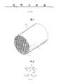
附图1是透视图,表示了本发明一种实施例的蜂窝状陶瓷构件的整体结构;Accompanying
附图2是示意图,表示了本发明一个实施例的蜂窝状陶瓷构件中的流体通道和隔板;Accompanying
附图3是曲线图,表示了蜂窝状陶瓷构件的正面开口面积与隔板厚度之间的关系;Accompanying
附图4是曲线图,表示了蜂窝状陶瓷构件的整体密度和隔板厚度之间的关系;Accompanying
附图5是曲线图,表示了正面开口面积与外壁变形度之间的关系;Accompanying
附图6A和6B表示了紧接着挤压出蜂窝状陶瓷构件之后对它进行传送的方式,以及在传送的过程中隔板发生局部变形的情形;Accompanying drawing 6A and 6B have shown the mode that it is conveyed immediately after extruding the ceramic honeycomb structure, and the situation that the partition takes place local deformation in the process of conveying;
附图7是曲线图,表示了蜂窝状陶瓷构件的隔板间隔与正面开口面积之间的关系;
附图8表示了用于测量蜂窝状陶瓷构件的压力损失特性的测量系统;Accompanying drawing 8 has represented the measurement system that is used for measuring the pressure loss characteristic of honeycomb ceramic member;
附图9是曲线图,表示了用附图8中所示系统所测量的压力损失特性;
附图10是曲线图,表示了压力损失随正面开口面积而变化的情况,它是在保持空气流量恒定的条件下用如附图8所示的系统测得的;
附图11表示了采用实际发动机对蜂窝状陶瓷构件进行测试的测试系统;Accompanying
附图12是曲线图,表示了采用附图11所示的测试系统所获得的发动机输出特性;
附图13A表示了以LA-4模式作为车辆运行测试模式的代表性实例所获得的车辆速度分布图;Accompanying drawing 13A has represented the vehicle velocity profile obtained with LA-4 mode as the representative example of vehicle operation test mode;
附图13B进一步详细地表示了按照LA-4模式在最初的505秒中的车辆速度分布图;Accompanying drawing 13B shows in further detail the vehicle speed profile in the first 505 seconds according to the LA-4 mode;
附图14是曲线图,表示了按照LA-4模式在最初的505秒中所累计的碳氢化合物排放量;Figure 14 is a graph showing cumulative hydrocarbon emissions for the first 505 seconds in accordance with the LA-4 model;
附图15是曲线图,表示了按照LA-4模式在最初的505秒中的碳氢化合物排放量与蜂窝状陶瓷构件的隔板厚度之间的关系;Accompanying drawing 15 is a graph showing the relationship between the amount of hydrocarbon emissions in the first 505 seconds and the thickness of the partition of the honeycomb ceramic structure according to the LA-4 model;
附图16是曲线图,表示了碳氢化合物排施量与蜂窝状陶瓷构件催化器的热容量之间的关系;Accompanying drawing 16 is a graph showing the relationship between the amount of hydrocarbon exhaust and the heat capacity of the honeycomb ceramic component catalyst;
附图17是曲线图,表示了对各种排气成分的净化效率与蜂窝状瓷体的热容量之间的关系;Accompanying drawing 17 is a graph showing the relationship between the purification efficiency of various exhaust components and the heat capacity of the honeycomb porcelain body;
附图18是曲线图,表示了按照LA-4模式在最初的505秒中各种蜂窝状陶瓷构件的温度变化;Accompanying drawing 18 is a graph showing the temperature change of various honeycomb ceramic structures in the first 505 seconds according to the LA-4 model;
附图19是曲线图,表示了按LA-4模式在最初的505秒中各种排放气体成分的排放量;Figure 19 is a graph showing the emissions of various exhaust gas components in the first 505 seconds in the LA-4 mode;
附图20表示了蜂窝状陶瓷构件中隔板中心线的定义;Accompanying drawing 20 has shown the definition of the dividing plate center line in the honeycomb ceramic structure;
附图21A、21B和21C表示了蜂窝状陶瓷构件隔板的各种弯曲变形方式以及相应于各变形方式的变形量;Accompanying drawing 21A, 21B and 21C have shown the various bending deformation modes of honeycomb ceramic component separator and the deformation amount corresponding to each deformation mode;
附图22是曲线图,表示了匀压强度与隔板的最大弯曲变形量(长度比LB/LA)之间的关系;Accompanying drawing 22 is a graph showing the relationship between the uniform pressure strength and the maximum bending deformation (length ratio LB /LA ) of the separator;
附图23是曲线图,表示了隔板在蜂窝状陶瓷构件的横截面方向上产生弯曲变形的几率;Accompanying drawing 23 is a graph, has represented the probability that the partition produces bending deformation in the cross-sectional direction of the honeycomb ceramic structure;
附图24是曲线图,表示了匀压强度以及其长度比LB/LA在1.10和1.15范围之内的隔板数与隔板总数的比例之间的关系;Accompanying drawing 24 is a graph showing the relationship between the isostatic strength and the ratio of the number of partitions to the total number of partitions for which the length ratio LB /LA is within the range of 1.10 and 1.15;
附图25A和25B表示了已产生弯曲变形的隔板的各种可能的形式;Accompanying drawing 25A and 25B have represented the various possible forms of the diaphragm that has produced bending deformation;
附图26表示了具有正方形横截面流体通道的蜂窝状陶瓷构件隔板的挤压变形量;Accompanying drawing 26 has represented the extruding deformation amount of the honeycomb ceramic component separator with square cross-section fluid channel;
附图27A和27B分别表示了具有六边形流体通道的蜂窝状陶瓷构件隔板在挤压变形之前和之后的状态;Accompanying drawing 27A and 27B respectively have represented the state before and after extrusion deformation of the honeycomb ceramic member separator with hexagonal flow channel;
附图28是曲线图,表示了在具有正方形横截面流体通道情况下匀压强度与对角线长度比Lmax/Lmin之间的关系,并以隔板厚度作为参数;Accompanying drawing 28 is a graph showing the relationship between the uniform pressure strength and the diagonal length ratio Lmax/Lmin in the case of a fluid channel with a square cross section, and the thickness of the partition is used as a parameter;
附图29是曲线图,表示了在具有六边形横截面流体通道情况下匀压强度与对角线长度比Lmax/Lmin之间的关系,并以隔板厚度作为参数;Accompanying drawing 29 is a graph showing the relationship between the uniform pressure strength and the diagonal length ratio Lmax/Lmin in the case of a hexagonal cross-section fluid channel, and the thickness of the partition is used as a parameter;
附图30A和30B表示了在具有正方形横截面流体通道的蜂窝状陶瓷构件中隔板的产生缺陷的状态;Accompanying drawing 30A and 30B have shown the state that the separator produces defect in the honeycomb ceramic structure that has square cross-section fluid channel;
附图31是曲线图,表示了匀压强度与隔板总数中的有缺陷的隔板数目之间的关系,并以隔板厚度作为参数;Accompanying drawing 31 is a graph showing the relationship between the isostatic strength and the number of defective partitions in the total number of partitions, and the thickness of the partitions is used as a parameter;
附图32是曲线图,表示了匀压强度与外周区域中的有缺陷的隔板数目之间的关系,并以隔板厚度作为参数。Fig. 32 is a graph showing the relationship between the isostatic strength and the number of defective partitions in the peripheral region, using the thickness of the partitions as a parameter.
参见附图1,它表示了本发明的蜂窝状陶瓷构件的一种实施例,该蜂窝状陶瓷构件总地用附图标记10来表示。蜂窝状陶瓷构件具有外壁11和位于其中的隔板12。隔板12在蜂窝状陶瓷构件中划分出了许多具有多边形横截面的流体通道13,例如三角形、正方形或六边形的流体通道。这些流动通道沿着蜂窝状陶瓷构件的轴向方向延伸,以便让流体,例如内燃机的废气,由流体通道流出。如附图1所示,蜂窝状陶瓷构件的与其流体通道相垂直的横截面形状可以是圆形或环形。不过,蜂窝状陶瓷构件也可以具有不同的横截面形状,例如椭圆横截面并具有延长的圆形或椭圆轮廓,或其他的非圆形横截面。具有上述横截面形状的蜂窝状陶瓷构件本身是已知的,并已实际使用。此外,蜂窝状陶瓷构件10具有在流体通道13的方向上延伸的纵向轴线,它可以是直的,也可以通常的方式为弯曲形状,这一点本身是已知的。Referring to accompanying drawing 1, it has shown an embodiment of the honeycomb ceramic structure of the present invention, and this honeycomb ceramic structure is indicated generally by
本发明的蜂窝状陶瓷构件10可以用作例如汽车排气净化系统中的催化剂载体。蜂窝状陶瓷构件10可以是一个挤压而成的整体,基本上由堇青石、富铝红柱石、氧化铝、碳化硅、氮化硅或氧化锆组成,然而若考虑到耐热冲击特性,则整体挤压而成的蜂窝状陶瓷构件10最好由堇青石制成并具有正方形横截面的流体通道13。The
根据本发明,当蜂窝状陶瓷构件10例如用作催化剂载体时,一开始需在隔板12的表面上涂一层基础材料,例如γ-氧化铝或类似材料,其使用量相对于催化剂体积而言应不少于100g/l。随后,在基础材料的表面上附着催化材料,该材料可以是稀有金属Pt、Rh和Pd中的至少一种,其使用量相对于催化器体积而言应不少于2g/l。在这一情况下,如上所述的由涂有基础材料和催化材料的蜂窝状陶瓷构件构成的蜂窝状陶瓷催化器每m3的热容量不大于450kJ/K,最好不大于410fkJ/K。According to the present invention, when the honeycomb
根据本发明,蜂窝状陶瓷构件10的A-轴抗压强度不小于50kgf/cm2,B-轴抗压强度不小于5kgf/cm2,最好不小于10kgf/cm2。陶瓷蜂窝状构件10的外壁11的厚度至少为0.1mm,隔板12的厚度t(参见附图2)在0.050mm至0.150mm的范围之内。此外,根据本发明,陶瓷蜂窝状构件10的正面开口面积OFA和整体密度G分别满足如下的关系式(1)和(2):According to the present invention, the honeycomb
0.65≤OFA≤-0.58×t+0.98 ……(1)0.65≤OFA≤-0.58×t+0.98 ... (1)
k×{1-(-0.58×t+0.98)}≤G≤k×0.35 ……(2)k×{1-(-0.58×t+0.98)}≤G≤k×0.35 ……(2)
其中K为一参数,由构成蜂窝状陶瓷构件的瓷质材料的实体比重乘以(1-材料的疏松度)。Among them, K is a parameter, which is multiplied by the specific gravity of the porcelain material constituting the honeycomb ceramic component by (1-the porosity of the material).
如本技术领域里的普通技术人员所知,蜂窝状陶瓷构件正面开口面积OFA和整体密度G之间具有互补的关系,因此在材料的实体比重和疏松度已知的情况下,如果其中一个已被确定,则另一个就可以被计算出来。As known to those of ordinary skill in the art, there is a complementary relationship between the front opening area OFA of the honeycomb ceramic component and the overall density G, so when the specific gravity and porosity of the material are known, if one of them has been is determined, the other can be calculated.
本发明旨在如附图3和附图4分别所示那样确定隔板厚度t与正面开口面积OFA以及整体密度G之间的关系,图中所示的阴影区域为满足关系式(1)和(2)的区域。关系式(1)中的正面开口面积OFA的上限值(-0.58×t+0.98)是一个近似的表达式,它是根据如附图5所示的试验结果而获得的,在该试验中,以隔板厚度t作为参数,对各种样品的正面开口面积和外壁的局部变形之间的关系进行试验,并根据变形的程度来判断这些样品的可用性。The purpose of the present invention is to determine the relationship between the thickness t of the partition, the front opening area OFA and the overall density G as shown in Figure 3 and Figure 4 respectively, the shaded area shown in the figure is to satisfy the relational formula (1) and (2) area. The upper limit value (-0.58×t+0.98) of the front opening area OFA in relation (1) is an approximate expression, which is obtained according to the test results shown in Figure 5. In this test , using the partition thickness t as a parameter, the relationship between the front opening area of various samples and the local deformation of the outer wall is tested, and the usability of these samples is judged according to the degree of deformation.
具体说来,如附图6A所示,在挤压出蜂窝状陶瓷构件之后,便立即将它们暂时放在一个托板上运往下一工序,蜂窝状陶瓷构件的外壁表面与托板的基本上平坦的支持表面相接触。在运送的过程中,由于陶瓷蜂窝状构件还是软的,因此其外壁会产生如附图6B所示的局部变形。如果蜂窝状陶瓷构件的外壁产生了这样的局部变形,在封装的过程中就会产生蜂窝状陶瓷构件的偏差接触,或者使位于局部变形外壁附近的隔板产生进一步的变形,从而增大了降低匀压强度和/或使蜂窝状陶瓷构件产生破裂的可能性。Specifically, as shown in accompanying drawing 6A, immediately after extruding the honeycomb ceramic components, they are temporarily placed on a pallet to be transported to the next process, and the outer wall surface of the honeycomb ceramic component is basically contact with a flat support surface. During transportation, since the ceramic honeycomb structure is still soft, its outer wall will undergo local deformation as shown in Fig. 6B. If such local deformation occurs on the outer wall of the honeycomb ceramic component, deviation contact of the honeycomb ceramic component will occur during the packaging process, or further deformation of the partition near the locally deformed outer wall will occur, thereby increasing the decrease Uniform compressive strength and/or the possibility of cracking the honeycomb ceramic structure.
因此,在判断蜂窝状陶瓷构件的合格性时,需要考虑蜂窝状陶瓷构件外壁变形程度与正面开口面积之间的关系。如本技术领域里的普通技术人员所知,增大正面开口面积OFA会降低蜂窝巢室的密度,减少构成蜂窝状结构的隔板数量,并增大支持外壁的隔板的间距(巢室的间距)。附图7表示了正面开口面积OFA与隔板间距之间的关系,由该图可以清楚地看到,对于任何隔板厚度来说,在正面开口面积达到一定数值之后,隔板间距就会急剧增大。对正面开口面积OFA与隔板厚度之间的关系还作了进一步的试验,其结果证实了当正面开口面积OFA超过-0.58×t+0.98时,隔板之间所支持的外壁就会产生缺陷。人们还证实了外壁的上述缺陷具有增大外壁局部变形并使与外壁相邻的隔板产生进一步变形的趋势,从而降低蜂窝状陶瓷构件的匀压强度。如果蜂窝状陶瓷构件的隔板和外壁具有理想的精确形状,不存在变形,那么施加匀压的负荷就会在蜂窝状陶瓷构件中产生占主导地位的压应力场;然而如果存在变形,就会在变形区域产生拉应力,此时匀压强度取决于拉应力,从而使匀压强度急剧下降。Therefore, when judging the qualification of the honeycomb ceramic component, it is necessary to consider the relationship between the degree of deformation of the outer wall of the honeycomb ceramic component and the area of the front opening. As known to those of ordinary skill in the art, increasing the open frontal area OFA reduces the density of the honeycomb cells, reduces the number of partitions that make up the honeycomb structure, and increases the spacing of the partitions that support the outer walls (cell spacing). spacing). Accompanying drawing 7 shows the relationship between the front opening area OFA and the spacing between the partitions. It can be clearly seen from this figure that for any partition thickness, after the front opening area reaches a certain value, the spacing between the partitions will be sharp. increase. Further experiments were carried out on the relationship between the front opening area OFA and the thickness of the partition, and the results confirmed that when the front opening area OFA exceeds -0.58×t+0.98, defects will occur on the outer wall supported by the partitions . It has also been confirmed that the above-mentioned defects of the outer wall have a tendency to increase the local deformation of the outer wall and cause further deformation of the partitions adjacent to the outer wall, thereby reducing the isostatic strength of the honeycomb ceramic structure. If the separators and outer walls of the honeycomb ceramic structure have the ideal precise shape and there is no deformation, then the application of uniform pressure will generate a dominant compressive stress field in the honeycomb ceramic structure; however, if there is deformation, it will Tensile stress is generated in the deformed area, and the uniform compressive strength depends on the tensile stress at this time, so that the uniform compressive strength drops sharply.
以下将根据各种试验结果来说明满足上述条件的本发明蜂窝状陶瓷构件10以及蜂窝状陶瓷构件催化器的优良特性。The excellent characteristics of the honeycomb
进行了试验来确定本发明的蜂窝状陶瓷构件的压力损失特性与正面开口面积之间的关系。附图8表示了用于测量蜂窝状陶瓷构件的压力损失特性的测量系统20。该测量系统20包括一个鼓风机21,一个流体引导部分22和一个测量部分23。在用该系统来进行测量时,将需要测量其压力损失的物件,亦即蜂窝状陶瓷构件24,放在测量部分23中,启动鼓风机21,由流体引导部分22输送压缩空气并使之流过蜂窝状陶瓷构件的流体通道,通过与测量部分相连接的压力表25来测量蜂窝状陶瓷构件24的压力损失,亦即蜂窝状陶瓷构件24的上游端和下游端之间的压力差。采用上述测量系统20,通过改变空气流体速度,测量一系列的蜂窝状陶瓷构件的压力损失特性,每一个蜂窝状陶瓷构件具有恒定的大小(横截面和体积),但是不同的正面开口面积。Experiments were conducted to determine the relationship between the pressure loss characteristics and the front face opening area of the honeycomb ceramic structure of the present invention. Fig. 8 shows a
附图9表示了对上述系列的蜂窝状陶瓷构件的压力损失特性的测量结果,由它可以清楚地看出压力损失随着正面开口面积OFA的减小而增大。附图10进一步表示了同一系列的蜂窝状陶瓷构件的压力损失随正面开口面积OFA的变化而变化的情况,其中空气流量保持恒定(5m3/min)。由附图10可以看出:压力损失随正面开口面积OFA的减小而增大的趋势在正面开口面积小于70%时,特别是小于65%时,就得更加显著。这一点表明选取正面开口面积的下限值为65%(=0.65)是较为理想的,最好为70%(=0.70)。Fig. 9 shows the measurement results of the pressure loss characteristics of the above series of honeycomb ceramic structures, from which it can be clearly seen that the pressure loss increases with the decrease of the front opening area OFA. Figure 10 further shows how the pressure loss of the same series of honeycomb ceramic components varies with the change of the open front area OFA, where the air flow rate is kept constant (5m3 /min). It can be seen from accompanying drawing 10 that the pressure loss increases with the decrease of the front opening area OFA, which is more significant when the front opening area is less than 70%, especially when it is less than 65%. This shows that it is more ideal to select the lower limit of the front opening area as 65% (=0.65), preferably 70% (=0.70).
其次,将解释本发明的蜂窝状陶瓷构件10,特别是其正面开口面积OFA对内燃机输出特性的影响。附图11表示了对一个实际内燃机的输出特性进行测量的测试机构30,它包括一个排量为3000cc的六缸汽油发动机31,接有一个长度为50cm的排气歧管32。一个装有蜂窝状陶瓷构件(被测对象)的转换器33直接与排气歧管32的下游端相连接,在转换器33的下游端连接了一个排量为1700cc的安装在车地板下的转换器34,在转换器34的下游端连接了一个消音器35,在发动机31的输出轴上安装了一个测力器36。采用上述测试系统,通过测力器36来测量发动机31处于最大输出状态时的输出力。将一组转换器33依次直接安装在排气歧管32的下游端进行测量,该组转换器中装有由蜂窝状陶瓷构件构成的催化剂载体,这些蜂窝状陶瓷构件具有相同的大小(排量为1700cc),但具有不同的正面开口面积。测量的结果如附图12所示,由它可以看出:发动机输出随蜂窝状陶瓷构件正面开口面积的减小而减小的趋势在正面开口面积小于70%,尤其是小于65%时变得十分显著。Next, the effect of the honeycomb
下面将说明采用汽车排气净化系统所获得的排气净化性能,该净化系统采用了由本发明的蜂窝状陶瓷构件10所构成的蜂窝状陶瓷催化器。Next, exhaust gas purification performance obtained by an automobile exhaust gas purification system using a honeycomb ceramic catalyst composed of the
如本技术领域里的普通技术人员所知,对实际车辆在工作状态下的排气测量通常是根据由特定测试驱动模式所确定的预定车辆速度来完成的。图13A示出作为这种测试驱动模式的一个例子的LA-4模式的车辆速度分布图,附图13B更详细地表示了按照LA-4模式在最初的505秒中的车辆速度分布图。As is known to those of ordinary skill in the art, exhaust gas measurements on an actual vehicle under operating conditions are typically performed at a predetermined vehicle speed determined by a particular test drive pattern. Figure 13A shows the vehicle speed profile for LA-4 mode as an example of such a test drive mode, and Figure 13B shows the vehicle speed profile for the first 505 seconds in LA-4 mode in more detail.
根据LA-4模式的汽车速度分布图,采用装有其排量为2500cc的六缸汽油发动机的汽车在工作状态下进行排气测量,在测量过程中将一系列的催化转换器依次装在排气系统的排气歧管的下游端。上述转换器分别装有蜂窝状瓷质催化剂载体,它们具有相同的大小或体积和相同的巢室密度,即1200cc和60巢室/cm2,但具有不同的隔板厚度。测量每一种转换器在LA-4模式的最初505秒中的碳氢化合物(HC)累计排放量。附图14表示了测量的结果,由它可以看出:减小隔板的厚度能够降低碳氢化合物的排放量。According to the vehicle speed distribution diagram of LA-4 mode, a vehicle equipped with a six-cylinder gasoline engine with a displacement of 2500cc is used to measure the exhaust gas under working conditions. During the measurement process, a series of catalytic converters are installed in the row downstream end of the exhaust manifold of the gas system. The above-mentioned converters were respectively equipped with honeycomb ceramic catalyst supports, which had the same size or volume and the same cell density, ie, 1200 cc and 60 cells/cm2 , but had different separator thicknesses. Cumulative hydrocarbon (HC) emissions were measured for each converter during the first 505 seconds of LA-4 mode. Accompanying drawing 14 shows the result of the measurement, it can be seen that reducing the thickness of the separator can reduce the emission of hydrocarbons.
附图15表示了在LA-4模式的最初505秒中的碳氢化合物排放量,该数据是采用同一系列的转换器所获得的。由附图15可以看出:减小隔板厚度可以降低碳氢化合物排放量,当隔板厚度小于0.124mm时,碳氢化合物排放量降低的趋势变得更加显著。Figure 15 shows the hydrocarbon emissions during the first 505 seconds of LA-4 mode, obtained with the same series of converters. It can be seen from Figure 15 that reducing the thickness of the partition can reduce the emission of hydrocarbons, and when the thickness of the partition is less than 0.124mm, the tendency of reducing the emission of hydrocarbons becomes more significant.
通过进一步的试验来确定碳氢化合物排放量与催化器热容量之间的关系,所获得的结果如附图16所示。由该附图可以看出:减小热容量可以降低碳氢化合物排放量,而且碳氢化合物排放量降低的趋势当热容量小于450kJ/m3时,尤其是小于410kJ/m3时,变得更加显著。Further experiments were conducted to determine the relationship between the hydrocarbon emissions and the heat capacity of the catalyst, and the obtained results are shown in Figure 16. It can be seen from the figure that reducing the heat capacity can reduce the emission of hydrocarbons, and the trend of reducing the emission of hydrocarbons becomes more significant when the heat capacity is less than 450kJ/m3 , especially when it is less than 410kJ/m3 .
还通过更进一步的试验来确定催化器热容量与每一种排放成分(NOX、CO、HC)直至达到所谓“袋形A2峰值”的净化效率。该试验所获得的数据如附图17所示,由它可以看出:减小热容量可以提高对每一种排放成分的净化效率,这一提高的趋势当热容量小于450kJ/m3时,尤其是在小于410kJ/m3时,变得更加显著。Further tests were carried out to determine the heat capacity of the catalyst and the purification efficiency of each emission component (NOX, CO, HC) up to the so-called "pocket A2 peak". The obtained data of this experiment are shown in accompanying drawing 17, can find out by it: reduce heat capacity and can improve the purification efficiency to every kind of discharge component, the tendency of this improvement is when heat capacity is less than 450kJ/m3 , especially It becomes more significant when it is less than 410kJ/m3 .
如本技术领域里的普通技术人员所知,汽车排气净化系统在冷启动状态下的性能主要是取决于催化剂载体本身的温度上升特性,通过减小催化剂载体的整体密度,亦即减小催化器的热容量,就能够改善该净化特性。因此,在LA-4模式的最初505秒中,采用装有其排量为2500cc的六缸汽油发动机的测试汽车来测量催化剂载体的温度,在测量过程中将一系列的催化转换器依次装在排气系统的排气歧管的下游端,每一个转换器蜂窝状瓷质催化剂载体同样具有相同的大小或溶剂以及相同的巢室密度,即1200cc和60巢室/cm2,但具有不同的隔板厚度。每一催化剂载体的温度是在载体的中心部位来测量的,该部位与排气进口相距15mm。附图18表示了测量的结果,由它可以看出:减小隔板厚度,亦即减小催化剂载体的整体密度,就能够改善催化剂载体的温度上升特性。由附图18还可以看出:金属蜂窝状催化器与蜂窝状陶瓷催化器相比具有较低的温度上升速度,其原因是金属具有更高的导热性能,因而在温度上升过程中与陶瓷相比会散发更多的热量。As known to those of ordinary skill in the art, the performance of the automobile exhaust purification system in the cold start state mainly depends on the temperature rise characteristics of the catalyst carrier itself. By reducing the overall density of the catalyst carrier, that is, reducing the catalytic By increasing the heat capacity of the device, the purification characteristics can be improved. Therefore, during the first 505 seconds of the LA-4 mode, the temperature of the catalyst carrier is measured using a test car equipped with a six-cylinder gasoline engine with a displacement of 2500 cc, during which a series of catalytic converters are installed in sequence At the downstream end of the exhaust manifold of the exhaust system, each converter honeycomb ceramic catalyst support also has the same size or solvent and the same cell density, namely 1200cc and 60 cells/cm2 , but has a different Separator thickness. The temperature of each catalyst carrier was measured at the center of the carrier, which was 15 mm from the exhaust gas inlet. Accompanying drawing 18 has shown the measurement result, can find out from it: reduce the thickness of separator, namely reduce the overall density of catalyst carrier, just can improve the temperature rise characteristic of catalyst carrier. It can also be seen from accompanying drawing 18 that the metal honeycomb catalytic converter has a lower temperature rise rate than the honeycomb ceramic catalytic converter. than will dissipate more heat.
此外,在LA-4模式的最初505秒中,采用装有其排量为2500cc的六缸汽油发动机的汽车来测量各种排气成分(NOX、CO、HC)的排放量,在测量过程中将一系列的催化转换器依次装在排气系统的排气歧管的下游端,这些转换器分别装有金属蜂窝状催化器和蜂窝状陶瓷催化器。附图19表示了上述测量的结果,由它可以看出:蜂窝状陶瓷催化器的排气净化性能优于金属蜂窝状催化器的排气净化性能。In addition, during the first 505 seconds of the LA-4 mode, the emissions of various exhaust components (NOX, CO, HC) were measured using a car equipped with its six-cylinder gasoline engine with a displacement of 2500cc. During the measurement A series of catalytic converters are sequentially installed at the downstream end of the exhaust manifold of the exhaust system, and these converters are respectively equipped with metal honeycomb catalysts and honeycomb ceramic catalysts. Accompanying drawing 19 has represented the result of above-mentioned measurement, can find out from it: the exhaust gas purification performance of honeycomb ceramic catalyst is better than the exhaust gas purification performance of metal honeycomb catalyst.
如上所述,本发明的蜂窝状陶瓷构件10的A-轴抗压强度不小于50kgf/cm2,其B-轴抗压强度不小于5kgf/cm2。为了改善蜂窝状陶瓷构件的抗压强度,发明人进行了调查和试验,其结果表明:隔板在陶瓷蜂窝状构件制造过程中可能产生的变形和缺陷会明显地降低蜂窝状陶瓷构件的抗压强度。发明人进一步认识到:在采用薄壁结构的蜂窝状陶瓷构件时,为了获得优良的抗压强度,十分重要的是将隔板的变形程度和不连续度或类似缺陷分别限制在预定的允许范围之内。As described above, the honeycomb
首先对一种可能出现的变形方式,亦即隔板的弯曲变形进行说明。尽管隔板的弯曲变形更为经常地发生在隔板与外壁相邻的区域,但是在其他部位上,例如蜂窝状陶瓷构件的内部,也可能产生弯曲变形。通过在流体通道的方向上观察蜂窝状陶瓷构件,就可以知道是否存在弯曲变形,例如隔板的拱曲。Firstly, a possible deformation mode, that is, the bending deformation of the separator, will be described. Although the bending deformation of the separator more often occurs in the region adjacent to the outer wall of the separator, bending deformation may also occur in other locations, such as the interior of the honeycomb ceramic structure. By observing the honeycomb ceramic structure in the direction of the fluid passage, it can be known whether there is bending deformation, such as bowing of the partition.
例如,对于单元隔板,亦即在蜂窝状陶瓷构件中形成了任何一个流动通道,并可能产生弯曲变形的隔板来说,为了定量地确定弯曲变形的程度,定义出单元隔板的中心线是十分有用的。更具体地说,如附图20所示,单元隔板的中心线可以被定义为这样一条线,它通过与隔板两个侧面相切的一系列圆周的圆心。在上述中心线上任意取不同的两点,设这两点之间的实际中心线长度为LB,它们之间的直线距离为LA。显然,当隔板存在弯曲变形时,LB就始终大于LA。这样,弯曲变形的程度卞可以用如附图21A所示的长度比LB/LA来表示。先取用于计算长度比LB/LA的中心线上的两点,使长度比LB/LA达到其最大值。至于说到弯曲变形的形状,则除了隔板在其整个长度上弯曲成弧形形状之外,还存在其他的类型,例如附图21B和21C所示那样,隔板的中心线由两段彼此成一定角度的线段构成,或隔板仅仅局部地产生弯曲。For example, for a cell separator, that is, any flow channel is formed in a honeycomb ceramic member, and a separator that may undergo bending deformation, in order to quantitatively determine the degree of bending deformation, the center line of the cell separator is defined is very useful. More specifically, as shown in Figure 20, the centerline of a cell partition can be defined as a line passing through the center of a series of circles tangent to both sides of the partition. Take two different points arbitrarily on the above center line, let the actual center line length between these two points be LB , and the straight-line distance between them be LA . Obviously, when there is bending deformation of the separator, LB is always greater thanLA . Thus, the degree of bending deformation can be expressed by the length ratio LB /LA as shown in Fig. 21A. First take two points on the center line for calculating the length ratio LB /LA , so that the length ratio LB /LA reaches its maximum value. As for the shape of the bending deformation, there are other types besides the curved shape of the diaphragm over its entire length. Formed by line segments at an angle, or the partition is only partially bent.
根据本发明,基本上对于蜂窝状结构中的所有隔板来说,最好使长度比LB/LA保持在1至1.10的范围之内,并确保其长度比LB/LA在1.10到1.15范围之内的隔板数目不超过隔板总数的1%。According to the present invention, it is preferable to maintain the length ratio LB /LA within the range of 1 to 1.10 for substantially all partitions in the honeycomb structure, and to ensure that the length ratio LB /LA is 1.10 The number of partitions within the range of 1.15 does not exceed 1% of the total number of partitions.
附图22是曲线图,表示了匀压强度与变形量的关系,其中后者即为蜂窝状陶瓷构件隔板的长度比LB/LA的最大值。在进行匀压破坏性测试之前,首先测量已产生较大变形,从而预计可能成为破坏点的每一个隔板的长度比LB/LA。对具有不同隔板厚度的一系列蜂窝状陶瓷构件进行匀压破坏性测试,以便了解匀压强度与位于破坏点的隔板的长度比LB/LA之间的关系。每一个经受上述匀压破坏性测试的蜂窝状陶瓷构件都具有标准的尺寸,它们都是圆形的,其外径大约为100mm。在附图22中,上部的曲线为具有较厚隔板的蜂窝状陶瓷构件的数据,而下部的曲线为具有较薄隔板的蜂窝状陶瓷构件的数据。这一测试表明:当长度比LB/LA低于1.10或更低时,匀压强度就会显著地增大。Accompanying drawing 22 is a graph showing the relationship between the uniform pressure strength and the amount of deformation, wherein the latter is the maximum value of the length ratio LB /LA of the separator of the honeycomb ceramic structure. Before carrying out the uniform pressure destructive test, the length ratio LB /LA of each partition that has produced a large deformation is firstly measured to predict the possible failure point. Isostatic destructive tests were performed on a series of honeycomb ceramic structures with different separator thicknesses in order to understand the relationship between the isostatic strength and the length ratio LB /LA of the separator located at the failure point. Each of the honeycomb ceramic structures subjected to the above isostatic destructive test has standard dimensions, and they are all circular with an outer diameter of about 100 mm. In FIG. 22, the upper curve is the data of the honeycomb ceramic structure with thicker separators, and the lower curve is the data of the honeycomb ceramic structure with thinner separators. This test shows that the isostatic strength increases significantly when the length ratio LB /LA is lower than 1.10 or lower.
附图23中的曲线表示了从统计的角度来看,在一个蜂窝状陶瓷构件的任意横截面部位上已产生弯曲变形的隔板的长度比LB/LA的分布状况。Fig. 23 is a graph showing, from a statistical point of view, the distribution of the length ratio LB /LA of the partitions which have undergone bending deformation at an arbitrary cross-sectional portion of a honeycomb ceramic structure.
该曲线以图形的方式表示了变形隔板产生各种长度比LB/LA的几率。很明显,所述的几率取决于每一隔板的长度比LB/LA。当然存在着这样的蜂窝状陶瓷构件,其中所有的隔板都具有1.10或更小的长度比LB/LA,也存在这样的蜂窝状陶瓷构件,其中某些隔板的长度比LB/LA超过了1.10。The curve graphically represents the probability of deforming the diaphragm for various length ratios LB /LA . Obviously, said probability depends on the length ratio LB /LA of each partition. Of course there are honeycomb ceramic structures in which all the partitions have a length ratio LB /LA of 1.10 or less, and honeycomb ceramic structures in which some of the partitions have a length ratio LB /LALA exceeded 1.10.
附图24中的曲线表示了匀压强度与比值(N′/N)×100之间的关系,其中N′表示其长度比LB/LA在1.10与1.15之间的变形隔板的数目,而N为隔板总数。在附图24中,位于上部的曲线表示了具有较厚隔板的蜂窝状陶瓷构件的数据,而位于下部的曲线为具有较薄隔板的蜂窝状陶瓷构件的数据。由该曲线可以看出:当上述比值降低到1%或更小时,匀压强度就明显地增大。The curve in Figure 24 shows the relationship between the isostatic strength and the ratio (N'/N) x 100, where N' represents the number of deformed partitions whose length ratio LB /LA is between 1.10 and 1.15 , and N is the total number of partitions. In Fig. 24, the upper curve shows the data of the honeycomb ceramic structure with thicker separators, and the lower curve shows the data of the honeycomb ceramic structure with thinner separators. It can be seen from the curve that when the above-mentioned ratio is reduced to 1% or less, the uniform pressure strength is obviously increased.
匀压强度呈现出这一趋势的原因在于:当变形隔板的数量比值增大时,连续出现如附图25A所示的两个或更多个变形隔板的几率就会更高,在这样的情况下,已产生可观变形的隔板可能处于彼此相邻的位置。就局部结构强度而言,具有上述连续多个变形隔板的蜂窝状陶瓷构件显然不同于如附图25B所示的其变形隔板分散开来,彼此相隔一个间距的陶瓷蜂窝状构件。换句话说,当变形隔板聚集在一起,形成变形隔板组时,巢室形的流体通道就更容易被压扁,因而也就降低了其结构强度。此外,在对变形隔板聚集在一起的蜂窝状陶瓷构件进行匀压破坏性测试时,具有较低结构强度的那一部分蜂窝状陶瓷构件区域就会成为破坏点,从而也就降低了匀压强度。The reason why the uniform compressive strength shows this trend is that when the ratio of the number of deformed partitions increases, the probability of two or more deformed partitions appearing in succession as shown in Figure 25A will be higher. In the case of , partitions that have undergone considerable deformation may be located adjacent to each other. In terms of local structural strength, the honeycomb ceramic structure with the above-mentioned continuous deformed partitions is obviously different from the ceramic honeycomb structure in which the deformed partitions are scattered and spaced apart from each other as shown in Fig. 25B. In other words, when the deformed partitions are gathered together to form a deformed partition group, the cell-shaped fluid channels are more likely to be crushed, thereby reducing their structural strength. In addition, when the uniform pressure destructive test is carried out on the honeycomb ceramic structure with deformed partitions gathered together, the area of the honeycomb ceramic structure with lower structural strength will become the failure point, thereby reducing the uniform pressure strength. .
试验表明:当变形隔板的上述比值超过1.0%时,形成上述聚集在一起的变形隔板组的几率变大,从而降低了匀压强度。相反,当变形隔板的上述比值等于或小于1.0时,形成上述变形隔板组的几率就较小,这使变形隔板彼此分散开来,提高了局部的结构强度,从而也就提高了均衡强度。Tests have shown that when the above-mentioned ratio of the deformed partitions exceeds 1.0%, the probability of forming the above-mentioned group of deformed partitions gathered together increases, thereby reducing the uniform pressure strength. On the contrary, when the above-mentioned ratio of the deformed partitions is equal to or less than 1.0, the probability of forming the above-mentioned deformed partition groups is small, which makes the deformed partitions disperse from each other, improves the local structural strength, and thus improves the balance. strength.
下面将对隔板的另一种可能的变形方式,亦即隔板的挤压变形进行说明。与上述隔板的弯曲变形不同,挤压变形是由于构成巢室型流体通道的相邻单元隔板之间的夹角产生变化而造成的。例如,当流体通道具有正方形的横截面时,挤压变形就是使流体通道的横截面变形成菱形。在这样的情况下,如附图26所示,可以认为蜂窝状陶瓷构件中的任何流体通道具有格点,每一个格点为一个最大内接圆的圆心,该内接圆至少和相邻单元隔板交点的三个角相接。借助连接一对相对格点的对角线,隔板的挤压变形程度就可以方便地定量表示为长度比Lmax/Lmin,其中Lmax为最长的对角线,而Lmin为最短的对角线。Another possible deformation mode of the partition, that is, extrusion deformation of the partition will be described below. Different from the bending deformation of the above-mentioned partitions, the extrusion deformation is caused by the change of the included angle between the partitions of adjacent cells constituting the cell-type fluid channel. For example, when the fluid channel has a square cross-section, extrusion deformation is to deform the cross-section of the fluid channel into a rhombus. In this case, as shown in Figure 26, it can be considered that any fluid channel in the honeycomb ceramic structure has grid points, each grid point is the center of a largest inscribed circle, and the inscribed circle is at least as close as the adjacent cell The three corners of the intersection of the partitions meet. With the help of diagonals connecting a pair of opposing grid points, the degree of extrusion deformation of the separator can be conveniently expressed quantitatively as the length ratio Lmax/Lmin, where Lmax is the longest diagonal and Lmin is the shortest diagonal .
当流体通道具有如附图26所示的正方形横截面时,上述长度比Lmax/Lmin最好在1到1.73的范围之内,当流体通道具有如附图27A和27B所示的六边形横截面时,长度比Lmax/Lmin最好在1.15到1.93的范围之内。附图28和29中的曲线分别表示了当流体通道横截面为正方形和六边形时长度比Lmax/Lmin与匀压强度之间的关系,并以隔板厚度作为参数。在附图28和29中,位于上部的曲线表示了具有较大厚度的隔板的数据,而下部的曲线表示了具有较小厚度的隔板的数据。由这些曲线可以看出:当正方形流体通道的长度比Lmax/Lmin等于或小于1.73,或当六边形流体通道的上述长度比等于或小于1.93时,匀压强度就会显著增大。When the fluid channel has a square cross section as shown in accompanying drawing 26, the above-mentioned length ratio Lmax/Lmin is preferably in the range of 1 to 1.73, when the fluid channel has a hexagonal cross section as shown in accompanying drawing 27A and 27B In cross-section, the length ratio Lmax/Lmin is preferably in the range of 1.15 to 1.93. The curves in Figures 28 and 29 respectively represent the relationship between the length ratio Lmax/Lmin and the uniform pressure strength when the cross-section of the fluid passage is square and hexagonal, and the thickness of the separator is used as a parameter. In FIGS. 28 and 29, the upper curves represent data for separators having a larger thickness, while the lower curves represent data for separators having a smaller thickness. It can be seen from these curves that when the length ratio Lmax/Lmin of the square fluid channel is equal to or less than 1.73, or when the above-mentioned length ratio of the hexagonal fluid channel is equal to or less than 1.93, the uniform pressure strength will be significantly increased.
除了上述隔板的弯曲变形和挤压变形之外,当蜂窝状陶瓷构件的任何横截面部位上出现间隔时,由于隔板在流体通道方向上的不连续性,也会降低蜂窝状陶瓷构件的匀压强度。附图30A和30B中表示了在流体通道的方向上观察到的上述不连续点。上述不连续点可能产生于格点之间的位置上,也可能产生在格点上。当出现一个不连续点时,无论是何种类型,都将缺陷的数目记为1。In addition to the above-mentioned bending deformation and extrusion deformation of the separator, when gaps appear on any cross-sectional portion of the honeycomb ceramic member, the discontinuity of the separator in the direction of the fluid passage will also reduce the strength of the honeycomb ceramic member. Uniform pressure strength. The aforementioned discontinuities observed in the direction of the fluid passage are shown in Figures 30A and 30B. The above-mentioned discontinuous points may be generated at positions between grid points, or may be generated at grid points. When a discontinuity occurs, regardless of the type, the number of defects is recorded as 1.
根据本发明,设NDT为具有在蜂窝状陶瓷构件的某一横截面上形成了间隔的不连续点的隔板的数目,N为蜂窝状陶瓷构件中的隔板总数,则NDT最好不大于N的1%。此外,对于包括从蜂窝状构件的最外围数起的第20圈内流体通道的蜂窝状陶瓷构件的外圆周区域而言,若以ND20表示在蜂窝状陶瓷构件的这一区域内具有不连续点的隔板的数目,则ND20最好小于蜂窝状陶瓷构件隔板总数的0.5%。According to the present invention, let NDT be the number of partitions with discontinuous points forming intervals on a certain cross section of the honeycomb ceramic structure, and N be the total number of partitions in the honeycomb ceramic structure, then NDT is the best Not more than 1% of N. In addition, for the outer peripheral region of the honeycomb ceramic member including the 20th circle of inner fluid passages counted from the outermost periphery of the honeycomb member, if ND20 is used to indicate that there is a discontinuity in this region of the honeycomb ceramic member The number of partitions at the point, thenND20 is preferably less than 0.5% of the total number of partitions in the honeycomb ceramic structure.
附图31和32的曲线分别表示了匀压强度与具有不连续点的隔板数目ND和ND20之间的关系,并以隔板厚度作为参数。在附图31和32中,位于上部的曲线表示了较厚隔板的数据,而位于下部的曲线表示了较薄隔板的数据。从附图31可以看出:当不连续隔板的数目ND在隔板总数N中所占的百分比(ND/N)×100等于或小于1.0%时,匀压强度就会显著地增大。考虑到位于蜂窝状陶瓷构件的上述外层区域中的不连续隔板的数目,作了进一步的试验,以便明确匀压强度与不连续隔板的位置之间的关系。如附图32所示,该试验表明:当位于蜂窝状陶瓷构件的上述外层区域中的不连续隔板数目ND20在隔板总数N中所占的百分比(ND20/N)×100%等于或小于0.5%时,匀压强度就会显著地增大。Figures 31 and 32 are curves showing the relationship between the isostatic strength and the number of partitionsND andND20 having discontinuities, respectively, with the thickness of the partition as a parameter. In Figures 31 and 32, the upper curves represent data for thicker separators, while the lower curves represent data for thinner separators. It can be seen from Figure 31 that when the percentage of the number ND of discontinuous partitions in the total number N of partitions (ND /N) × 100 is equal to or less than 1.0%, the uniform pressure strength will increase significantly big. Considering the number of discontinuous partitions located in the above-mentioned outer layer region of the honeycomb ceramic structure, further experiments were conducted in order to clarify the relationship between the isostatic strength and the position of the discontinuous partitions. As shown in Figure 32, the test shows that: when the number of discontinuous partitions ND20 in the above-mentioned outer layer region of the honeycomb ceramic structure accounts for the percentage of the total number N of partitions (ND20 /N) × 100% When it is equal to or less than 0.5%, the uniform pressure strength will increase significantly.
应该指出:以上结合附图所示的匀压强度数据都是由具有正方形横截面流体通道和圆形外形的蜂窝状陶瓷构件来获得的,但是只要满足本发明的上述条件,具有三角形或六边形横截面流体通道的蜂窝状陶瓷构件以及具有椭圆形外形的蜂窝状陶瓷构件同样可以获得基本上相同的功能和优点。It should be pointed out that the above uniform pressure strength data shown in conjunction with the accompanying drawings are all obtained from honeycomb ceramic components with a square cross-section fluid channel and a circular shape, but as long as the above-mentioned conditions of the present invention are met, there is a triangular or hexagonal structure. Essentially the same functions and advantages can also be obtained with a honeycomb ceramic member having a fluid channel having a circular cross-section and a honeycomb ceramic member having an elliptical shape.
根据以上对本发明的详细说明,可以看出:如果与已有技术相比,减小蜂窝状陶瓷构件隔板的厚度,就可以增大正面开口面积,减小压力损失,并且当采用这样的蜂窝状陶瓷构件来作为催化剂载体时可以减小蜂窝状陶瓷构件的热容量。此外,根据本发明,通过满足蜂窝状陶瓷构件的隔板厚度与正面开口面积和/或整体密度之间的特定关系,并在数量上将蜂窝状陶瓷构件制造过程中可能产生的隔板变形程度和不连续点数目或类似缺陷控制在特定范围之内,则即使采用薄的隔板结构,也仍然能够获得具有令人满意的抗压强度特性的蜂窝状陶瓷构件。According to the above detailed description of the present invention, it can be seen that if compared with the prior art, the thickness of the honeycomb ceramic component partition is reduced, the front opening area can be increased, and the pressure loss can be reduced, and when such a honeycomb is adopted When the honeycomb ceramic member is used as the catalyst carrier, the heat capacity of the honeycomb ceramic member can be reduced. In addition, according to the present invention, by satisfying a specific relationship between the thickness of the separator of the honeycomb ceramic member and the front opening area and/or the overall density, and quantifying the degree of deformation of the separator that may occur during the manufacturing process of the honeycomb ceramic member If the number of discontinuous points and the like are controlled within a specific range, a honeycomb ceramic structure with satisfactory compressive strength characteristics can be obtained even with a thin separator structure.
上述说明是结合本发明的一些最佳实施例来进行的,它们仅仅用作例子。在下述权利要求的范围之内还可以对本发明作出各种改进。The foregoing description has been made in connection with some preferred embodiments of the invention, which are provided by way of example only. Various modifications of the invention are possible within the scope of the following claims.
Claims (24)
Translated fromChineseApplications Claiming Priority (4)
| Application Number | Priority Date | Filing Date | Title |
|---|---|---|---|
| JP188,274/93 | 1993-07-29 | ||
| JP5188273AJP2892258B2 (en) | 1993-07-29 | 1993-07-29 | Ceramic honeycomb structure |
| JP188,273/93 | 1993-07-29 | ||
| JP5188274AJP2892259B2 (en) | 1993-07-29 | 1993-07-29 | Ceramic honeycomb catalyst |
Publications (2)
| Publication Number | Publication Date |
|---|---|
| CN1098029Atrue CN1098029A (en) | 1995-02-01 |
| CN1092082C CN1092082C (en) | 2002-10-09 |
Family
ID=26504828
Family Applications (1)
| Application Number | Title | Priority Date | Filing Date |
|---|---|---|---|
| CN94103343AExpired - LifetimeCN1092082C (en) | 1993-07-29 | 1994-03-25 | Ceramic honeycomb structural body and catalyst comprising the same |
Country Status (6)
| Country | Link |
|---|---|
| US (1) | US5494881A (en) |
| EP (1) | EP0636410B1 (en) |
| KR (1) | KR100297621B1 (en) |
| CN (1) | CN1092082C (en) |
| CA (1) | CA2119604C (en) |
| DE (1) | DE69405062T2 (en) |
Cited By (5)
| Publication number | Priority date | Publication date | Assignee | Title |
|---|---|---|---|---|
| CN100415688C (en)* | 2001-12-04 | 2008-09-03 | 株式会社电装 | Method and device for manufacturing honeycomb forming body in high humidity environment |
| CN103212451A (en)* | 2013-04-19 | 2013-07-24 | 中电投远达环保工程有限公司 | Honeycomb catalyst unit and honeycomb catalyst module |
| CN104245133A (en)* | 2012-03-30 | 2014-12-24 | 日本碍子株式会社 | Honeycomb structure |
| CN104508268A (en)* | 2012-05-24 | 2015-04-08 | 帝国革新有限公司 | Catalytic Converter Substrate |
| CN118976542A (en)* | 2024-07-31 | 2024-11-19 | 山东国瓷功能材料股份有限公司 | Honeycomb ceramic carrier, preparation method thereof and catalytic body containing the honeycomb ceramic carrier |
Families Citing this family (44)
| Publication number | Priority date | Publication date | Assignee | Title |
|---|---|---|---|---|
| US5866079A (en)* | 1993-09-03 | 1999-02-02 | Ngk Insulators, Ltd. | Ceramic honeycomb catalytic converter |
| ATE257904T1 (en)* | 1997-03-21 | 2004-01-15 | Kemira Metalkat Oy | CATALYTIC REACTOR |
| DE19749379A1 (en)* | 1997-11-07 | 1999-05-20 | Emitec Emissionstechnologie | Catalyst carrier body with improved heat radiation |
| US6540693B2 (en)* | 1998-03-03 | 2003-04-01 | Senorx, Inc. | Methods and apparatus for securing medical instruments to desired locations in a patients body |
| JP3544471B2 (en) | 1998-05-12 | 2004-07-21 | 日本碍子株式会社 | Hexagonal cell honeycomb structure and its gripping method |
| JP4453117B2 (en)* | 1998-09-29 | 2010-04-21 | 株式会社デンソー | Method for manufacturing hexagonal honeycomb structure |
| DE19921263A1 (en)* | 1999-05-07 | 2000-11-16 | Emitec Emissionstechnologie | Internal combustion engine with a small-volume catalyst |
| JP3862458B2 (en)* | 1999-11-15 | 2006-12-27 | 日本碍子株式会社 | Honeycomb structure |
| US6623704B1 (en)* | 2000-02-22 | 2003-09-23 | Delphi Technologies, Inc. | Apparatus and method for manufacturing a catalytic converter |
| JP4548968B2 (en)* | 2000-06-05 | 2010-09-22 | 株式会社日本自動車部品総合研究所 | Ceramic support and ceramic catalyst body |
| US6821492B1 (en)* | 2000-09-13 | 2004-11-23 | Delphi Technologies, Inc. | Stronger catalyst using selective washcoat location |
| JP2003164761A (en)* | 2001-09-21 | 2003-06-10 | Toshiba Corp | Metal oxide sintered structure and method of manufacturing the same |
| JP2003103181A (en)* | 2001-09-28 | 2003-04-08 | Ngk Insulators Ltd | Honeycomb catalyst, honeycomb intermediate, and method for producing honeycomb catalyst |
| JP2003326175A (en)* | 2002-03-07 | 2003-11-18 | Denso Corp | Carrier, method for producing the same, and catalyst body |
| JP3999001B2 (en)* | 2002-03-08 | 2007-10-31 | 日本碍子株式会社 | Honeycomb structure and canning structure containing the same |
| AU2003220810A1 (en)* | 2002-03-28 | 2003-10-13 | Ngk Insulators, Ltd. | Cell structural body, method of manufacturing cell structural body, and catalyst structural body |
| JP3936238B2 (en)* | 2002-05-20 | 2007-06-27 | 株式会社デンソー | Catalyst body and method for producing catalyst body |
| DE10225278A1 (en)* | 2002-06-04 | 2003-12-24 | Iav Gmbh | Exhaust gas catalyst and catalyst body, preferably for cleaning exhaust gases from internal combustion engines |
| ATE383502T1 (en)* | 2002-07-15 | 2008-01-15 | Volkswagen Ag | COMBUSTION ENGINE SYSTEM WITH A DIRECT-INJECTION OTTO ENGINE AND A CATALYST SYSTEM |
| JP4584555B2 (en)* | 2002-10-17 | 2010-11-24 | 株式会社デンソー | Ceramic catalyst body |
| US7435274B2 (en)* | 2003-02-27 | 2008-10-14 | Kabushiki Kaisha Toshiba | Metal particle-dispersed composite oxides, metal particle-dispersed composite oxide-sintered bodies, method of manufacturing metal particle-dispersed composite oxides, and hydrocarbon-based fuel reformer |
| JP4322542B2 (en)* | 2003-04-21 | 2009-09-02 | 日本碍子株式会社 | HONEYCOMB STRUCTURE, MANUFACTURING METHOD THEREOF, MOLDING BASE, AND EXHAUSTED FLUID PURIFICATION SYSTEM |
| US7807110B2 (en)* | 2004-03-12 | 2010-10-05 | Cormetech Inc. | Catalyst systems |
| US7776786B2 (en) | 2004-05-04 | 2010-08-17 | Cormetech, Inc. | Catalyst systems advantageous for high particulate matter environments |
| JP4238858B2 (en)* | 2005-09-20 | 2009-03-18 | 株式会社デンソー | Hex honeycomb structure and manufacturing method thereof |
| JP4788497B2 (en)* | 2005-12-27 | 2011-10-05 | 株式会社デンソー | Hex honeycomb structure |
| EP2363194B1 (en)* | 2006-08-01 | 2012-10-31 | Cormetech, Inc. | System for removing nitrogen oxides from an exhaust gas |
| CN101678348B (en)* | 2008-05-20 | 2012-07-18 | 揖斐电株式会社 | Honeycomb structure |
| JP5506220B2 (en)* | 2009-03-26 | 2014-05-28 | 日本碍子株式会社 | Ceramic honeycomb structure |
| CN103561864A (en)* | 2011-03-28 | 2014-02-05 | 康明公司 | Catalyst compositions and applications thereof |
| US20130098279A1 (en) | 2011-07-27 | 2013-04-25 | Cormetech, Inc. | Combustion Apparatus And Applications Thereof |
| JP6218251B2 (en)* | 2013-01-25 | 2017-10-25 | ヤラ・インターナショナル・アーエスアーYara International ASA | Honeycomb monolith structures used in processes with limited mass transfer and catalyst structures and reactors containing the same |
| CN105706284B (en)* | 2013-11-08 | 2018-09-18 | 本田技研工业株式会社 | Dual Power Supply Load Drive Fuel Cell System |
| WO2015182726A1 (en) | 2014-05-28 | 2015-12-03 | ユミコア日本触媒株式会社 | Catalyst for internal combustion engine exhaust gas purification, and system for same |
| US10711203B2 (en) | 2016-08-31 | 2020-07-14 | Exxonmobil Chemical Patents Inc. | Hydrocarbon pyrolysis |
| WO2018044557A1 (en) | 2016-08-31 | 2018-03-08 | Exxonmobil Chemical Patents Inc. | Pyrolysis reactor approach temperature |
| US10577292B2 (en) | 2016-08-31 | 2020-03-03 | Exxonmobil Chemical Patents Inc. | Hydrocarbon conversion |
| WO2018044555A1 (en) | 2016-08-31 | 2018-03-08 | Exxonmobil Chemical Patents Inc. | Hydrocarbon pyrolysis |
| WO2018111811A1 (en)* | 2016-12-12 | 2018-06-21 | Cormetech, Inc. | Scr catalyst modules and associated catalytic reactors |
| JP6622741B2 (en) | 2017-03-07 | 2019-12-18 | 日本碍子株式会社 | Honeycomb structure |
| JP6792489B2 (en) | 2017-03-07 | 2020-11-25 | 日本碍子株式会社 | Honeycomb structure |
| WO2019204081A1 (en) | 2018-04-20 | 2019-10-24 | Exxonmobil Chemical Patents Inc. | Reverse flow reactors having low maldistribution parameter while containing asymmetric feeds, methods of using same, and pyrolysis products made from same |
| WO2019204082A1 (en) | 2018-04-20 | 2019-10-24 | Exxonmobil Chemical Patents Inc. | Reverse flow reactors having high purge efficiencies while containing asymmetric feeds, methods of using same, and pyrolysis products made from same |
| JP7029421B2 (en)* | 2019-02-28 | 2022-03-03 | 日本碍子株式会社 | Honeycomb structure coating material, honeycomb structure outer peripheral coating and honeycomb structure with outer peripheral coating |
Family Cites Families (4)
| Publication number | Priority date | Publication date | Assignee | Title |
|---|---|---|---|---|
| JPH084749B2 (en)* | 1985-01-21 | 1996-01-24 | 日本碍子株式会社 | Ceramic honeycomb structure |
| JPS61183182A (en)* | 1985-02-11 | 1986-08-15 | 株式会社デンソー | Porous ceramic structure |
| JPH0356354Y2 (en)* | 1986-04-08 | 1991-12-18 | ||
| US4955524A (en)* | 1989-08-24 | 1990-09-11 | General Motors Corporation | Extrusion die construction and its method of manufacture |
- 1994
- 1994-03-22CACA002119604Apatent/CA2119604C/ennot_activeExpired - Lifetime
- 1994-03-23USUS08/216,429patent/US5494881A/ennot_activeExpired - Lifetime
- 1994-03-23EPEP94302077Apatent/EP0636410B1/ennot_activeExpired - Lifetime
- 1994-03-23DEDE69405062Tpatent/DE69405062T2/ennot_activeExpired - Lifetime
- 1994-03-25CNCN94103343Apatent/CN1092082C/ennot_activeExpired - Lifetime
- 1994-03-25KRKR1019940006106Apatent/KR100297621B1/ennot_activeExpired - Lifetime
Cited By (8)
| Publication number | Priority date | Publication date | Assignee | Title |
|---|---|---|---|---|
| CN100415688C (en)* | 2001-12-04 | 2008-09-03 | 株式会社电装 | Method and device for manufacturing honeycomb forming body in high humidity environment |
| CN104245133A (en)* | 2012-03-30 | 2014-12-24 | 日本碍子株式会社 | Honeycomb structure |
| CN104245133B (en)* | 2012-03-30 | 2016-08-24 | 日本碍子株式会社 | Honeycomb structured body |
| CN104508268A (en)* | 2012-05-24 | 2015-04-08 | 帝国革新有限公司 | Catalytic Converter Substrate |
| US9630173B2 (en) | 2012-05-24 | 2017-04-25 | Imperial Innovations Limited | Catalytic converter substrate |
| CN104508268B (en)* | 2012-05-24 | 2018-02-06 | 帝国革新有限公司 | Catalytic converter substrates |
| CN103212451A (en)* | 2013-04-19 | 2013-07-24 | 中电投远达环保工程有限公司 | Honeycomb catalyst unit and honeycomb catalyst module |
| CN118976542A (en)* | 2024-07-31 | 2024-11-19 | 山东国瓷功能材料股份有限公司 | Honeycomb ceramic carrier, preparation method thereof and catalytic body containing the honeycomb ceramic carrier |
Also Published As
| Publication number | Publication date |
|---|---|
| KR100297621B1 (en) | 2001-10-22 |
| DE69405062D1 (en) | 1997-09-25 |
| DE69405062T2 (en) | 1998-02-05 |
| US5494881A (en) | 1996-02-27 |
| KR950002855A (en) | 1995-02-16 |
| EP0636410B1 (en) | 1997-08-20 |
| CN1092082C (en) | 2002-10-09 |
| CA2119604C (en) | 1997-02-18 |
| CA2119604A1 (en) | 1995-01-30 |
| EP0636410A1 (en) | 1995-02-01 |
Similar Documents
| Publication | Publication Date | Title |
|---|---|---|
| CN1098029A (en) | Honeycomb ceramic component and catalyst made of it | |
| EP1384507B1 (en) | Use of a honeycomb structure in an exhaust gas converter system | |
| JP4511396B2 (en) | Honeycomb structure and manufacturing method thereof | |
| US6162404A (en) | Ceramic catalytic converter | |
| EP1360991B1 (en) | Ceramic honeycomb structure | |
| EP1495791B1 (en) | Filter | |
| EP1736220A1 (en) | Honeycomb structured body | |
| CN103946182B (en) | Honeycomb structured body | |
| EP1586547A1 (en) | Coating material, ceramic honeycomb structure and method for production thereof | |
| EP1125704A1 (en) | Corrugated wall honeycomb structure and production method thereof | |
| JP3126697B2 (en) | High strength thin-walled honeycomb structure | |
| EP2127719B1 (en) | Honeycomb structure | |
| CN1816378A (en) | Honeycomb structural body and method of manufacturing the same | |
| JP2007229700A (en) | Honeycomb structure | |
| EP2500079B1 (en) | Honeycomb structure | |
| JP2892258B2 (en) | Ceramic honeycomb structure | |
| KR20080101889A (en) | Catalytic converter with improved start-up behaviour | |
| EP2108430A1 (en) | Honeycomb structure | |
| JP2892259B2 (en) | Ceramic honeycomb catalyst | |
| CN109967133A (en) | honeycomb structure | |
| JP6013243B2 (en) | Honeycomb catalyst body | |
| JP3394505B2 (en) | High strength thin-walled honeycomb structure | |
| JP5478309B2 (en) | Honeycomb structure | |
| US11471869B2 (en) | Honeycomb structure |
Legal Events
| Date | Code | Title | Description |
|---|---|---|---|
| C06 | Publication | ||
| PB01 | Publication | ||
| C10 | Entry into substantive examination | ||
| SE01 | Entry into force of request for substantive examination | ||
| C14 | Grant of patent or utility model | ||
| GR01 | Patent grant | ||
| C17 | Cessation of patent right | ||
| CX01 | Expiry of patent term | Expiration termination date:20140325 Granted publication date:20021009 |