CN109768156B - Magnetic random access memory and manufacturing method thereof - Google Patents
Magnetic random access memory and manufacturing method thereofDownload PDFInfo
- Publication number
- CN109768156B CN109768156BCN201810823818.1ACN201810823818ACN109768156BCN 109768156 BCN109768156 BCN 109768156BCN 201810823818 ACN201810823818 ACN 201810823818ACN 109768156 BCN109768156 BCN 109768156B
- Authority
- CN
- China
- Prior art keywords
- layer
- iridium
- layers
- magnetic
- electrode
- Prior art date
- Legal status (The legal status is an assumption and is not a legal conclusion. Google has not performed a legal analysis and makes no representation as to the accuracy of the status listed.)
- Active
Links
- 230000005291magnetic effectEffects0.000titleclaimsabstractdescription196
- 238000004519manufacturing processMethods0.000titleclaimsabstractdescription11
- 229910052741iridiumInorganic materials0.000claimsabstractdescription132
- GKOZUEZYRPOHIO-UHFFFAOYSA-Niridium atomChemical compound[Ir]GKOZUEZYRPOHIO-UHFFFAOYSA-N0.000claimsabstractdescription110
- 229910052715tantalumInorganic materials0.000claimsabstractdescription62
- GUVRBAGPIYLISA-UHFFFAOYSA-Ntantalum atomChemical compound[Ta]GUVRBAGPIYLISA-UHFFFAOYSA-N0.000claimsabstractdescription62
- 229910052751metalInorganic materials0.000claimsabstractdescription35
- 239000002184metalSubstances0.000claimsabstractdescription34
- 229910002056binary alloyInorganic materials0.000claimsabstractdescription33
- 150000002503iridiumChemical class0.000claimsabstractdescription24
- HTXDPTMKBJXEOW-UHFFFAOYSA-NdioxoiridiumChemical compoundO=[Ir]=OHTXDPTMKBJXEOW-UHFFFAOYSA-N0.000claimsabstractdescription18
- 229910000457iridium oxideInorganic materials0.000claimsabstractdescription18
- ZACYQVZHFIYKMW-UHFFFAOYSA-Niridium titaniumChemical compound[Ti].[Ir]ZACYQVZHFIYKMW-UHFFFAOYSA-N0.000claimsabstractdescription17
- 230000004888barrier functionEffects0.000claimsdescription138
- 125000006850spacer groupChemical group0.000claimsdescription70
- 238000009792diffusion processMethods0.000claimsdescription65
- 230000005641tunnelingEffects0.000claimsdescription45
- 230000005290antiferromagnetic effectEffects0.000claimsdescription24
- 239000004065semiconductorSubstances0.000claimsdescription22
- 238000000034methodMethods0.000claimsdescription19
- 239000000696magnetic materialSubstances0.000claimsdescription15
- 239000000463materialSubstances0.000claimsdescription15
- 239000004020conductorSubstances0.000claimsdescription13
- CPLXHLVBOLITMK-UHFFFAOYSA-Nmagnesium oxideInorganic materials[Mg]=OCPLXHLVBOLITMK-UHFFFAOYSA-N0.000claimsdescription10
- 239000000395magnesium oxideSubstances0.000claimsdescription10
- AXZKOIWUVFPNLO-UHFFFAOYSA-Nmagnesium;oxygen(2-)Chemical compound[O-2].[Mg+2]AXZKOIWUVFPNLO-UHFFFAOYSA-N0.000claimsdescription10
- 210000004027cellAnatomy0.000claims13
- 210000000352storage cellAnatomy0.000claims2
- 239000010410layerSubstances0.000description666
- BASFCYQUMIYNBI-UHFFFAOYSA-NplatinumChemical compound[Pt]BASFCYQUMIYNBI-UHFFFAOYSA-N0.000description29
- 238000005229chemical vapour depositionMethods0.000description17
- 229910017052cobaltInorganic materials0.000description17
- 239000010941cobaltSubstances0.000description17
- GUTLYIVDDKVIGB-UHFFFAOYSA-Ncobalt atomChemical compound[Co]GUTLYIVDDKVIGB-UHFFFAOYSA-N0.000description17
- 230000008569processEffects0.000description13
- 229910052697platinumInorganic materials0.000description12
- PXHVJJICTQNCMI-UHFFFAOYSA-NNickelChemical compound[Ni]PXHVJJICTQNCMI-UHFFFAOYSA-N0.000description11
- 238000000231atomic layer depositionMethods0.000description11
- 238000005240physical vapour depositionMethods0.000description11
- 239000002346layers by functionSubstances0.000description7
- 229910052759nickelInorganic materials0.000description7
- KDLHZDBZIXYQEI-UHFFFAOYSA-NPalladiumChemical compound[Pd]KDLHZDBZIXYQEI-UHFFFAOYSA-N0.000description6
- 238000000151depositionMethods0.000description6
- 229910052750molybdenumInorganic materials0.000description6
- 239000013078crystalSubstances0.000description5
- 229910001362Ta alloysInorganic materials0.000description4
- 230000002411adverseEffects0.000description4
- 230000008901benefitEffects0.000description4
- 239000003989dielectric materialSubstances0.000description4
- 238000005530etchingMethods0.000description4
- 238000004518low pressure chemical vapour depositionMethods0.000description4
- 238000000206photolithographyMethods0.000description4
- 238000004549pulsed laser depositionMethods0.000description4
- 229910052707rutheniumInorganic materials0.000description4
- 239000000758substrateSubstances0.000description4
- 238000000038ultrahigh vacuum chemical vapour depositionMethods0.000description4
- 229910003321CoFeInorganic materials0.000description3
- 229910019236CoFeBInorganic materials0.000description3
- ZOKXTWBITQBERF-UHFFFAOYSA-NMolybdenumChemical compound[Mo]ZOKXTWBITQBERF-UHFFFAOYSA-N0.000description3
- ZDZZPLGHBXACDA-UHFFFAOYSA-N[B].[Fe].[Co]Chemical compound[B].[Fe].[Co]ZDZZPLGHBXACDA-UHFFFAOYSA-N0.000description3
- 229910045601alloyInorganic materials0.000description3
- 239000000956alloySubstances0.000description3
- FQMNUIZEFUVPNU-UHFFFAOYSA-Ncobalt ironChemical compound[Fe].[Co].[Co]FQMNUIZEFUVPNU-UHFFFAOYSA-N0.000description3
- 238000009713electroplatingMethods0.000description3
- XEEYBQQBJWHFJM-UHFFFAOYSA-NironSubstances[Fe]XEEYBQQBJWHFJM-UHFFFAOYSA-N0.000description3
- 229910052742ironInorganic materials0.000description3
- 239000012528membraneSubstances0.000description3
- 239000011733molybdenumSubstances0.000description3
- 229910052763palladiumInorganic materials0.000description3
- 238000003860storageMethods0.000description3
- 229910000575Ir alloyInorganic materials0.000description2
- KJTLSVCANCCWHF-UHFFFAOYSA-NRutheniumChemical compound[Ru]KJTLSVCANCCWHF-UHFFFAOYSA-N0.000description2
- 229910052782aluminiumInorganic materials0.000description2
- 229910052804chromiumInorganic materials0.000description2
- 229910052802copperInorganic materials0.000description2
- 238000010586diagramMethods0.000description2
- 238000010894electron beam technologyMethods0.000description2
- 238000000407epitaxyMethods0.000description2
- 230000005294ferromagnetic effectEffects0.000description2
- 230000006870functionEffects0.000description2
- 229910052737goldInorganic materials0.000description2
- 230000003993interactionEffects0.000description2
- 229910044991metal oxideInorganic materials0.000description2
- 150000004706metal oxidesChemical group0.000description2
- 238000001451molecular beam epitaxyMethods0.000description2
- 230000003647oxidationEffects0.000description2
- 238000007254oxidation reactionMethods0.000description2
- TWNQGVIAIRXVLR-UHFFFAOYSA-Noxo(oxoalumanyloxy)alumaneChemical compoundO=[Al]O[Al]=OTWNQGVIAIRXVLR-UHFFFAOYSA-N0.000description2
- 238000004544sputter depositionMethods0.000description2
- 229910052721tungstenInorganic materials0.000description2
- XUIMIQQOPSSXEZ-UHFFFAOYSA-NSiliconChemical compound[Si]XUIMIQQOPSSXEZ-UHFFFAOYSA-N0.000description1
- ATJFFYVFTNAWJD-UHFFFAOYSA-NTinChemical compound[Sn]ATJFFYVFTNAWJD-UHFFFAOYSA-N0.000description1
- 230000004075alterationEffects0.000description1
- 239000002885antiferromagnetic materialSubstances0.000description1
- QVGXLLKOCUKJST-UHFFFAOYSA-Natomic oxygenChemical compound[O]QVGXLLKOCUKJST-UHFFFAOYSA-N0.000description1
- 230000015572biosynthetic processEffects0.000description1
- 230000015556catabolic processEffects0.000description1
- 230000008859changeEffects0.000description1
- 230000007797corrosionEffects0.000description1
- 238000005260corrosionMethods0.000description1
- 238000006731degradation reactionMethods0.000description1
- 230000006866deteriorationEffects0.000description1
- 239000002355dual-layerSubstances0.000description1
- 238000007772electroless platingMethods0.000description1
- 239000003302ferromagnetic materialSubstances0.000description1
- 230000009969flowable effectEffects0.000description1
- 239000011521glassSubstances0.000description1
- 238000003780insertionMethods0.000description1
- 230000037431insertionEffects0.000description1
- 239000011810insulating materialSubstances0.000description1
- ULFQGKXWKFZMLH-UHFFFAOYSA-Niridium tantalumChemical compound[Ta].[Ir]ULFQGKXWKFZMLH-UHFFFAOYSA-N0.000description1
- 229910052760oxygenInorganic materials0.000description1
- 239000001301oxygenSubstances0.000description1
- 238000002161passivationMethods0.000description1
- 238000000059patterningMethods0.000description1
- 238000005498polishingMethods0.000description1
- 229910052710siliconInorganic materials0.000description1
- 239000010703siliconSubstances0.000description1
- 230000003068static effectEffects0.000description1
- 230000035882stressEffects0.000description1
- 239000000126substanceSubstances0.000description1
- 238000006467substitution reactionMethods0.000description1
- 238000003878thermal agingMethods0.000description1
- 229910052718tinInorganic materials0.000description1
Images


Classifications
- H—ELECTRICITY
- H10—SEMICONDUCTOR DEVICES; ELECTRIC SOLID-STATE DEVICES NOT OTHERWISE PROVIDED FOR
- H10N—ELECTRIC SOLID-STATE DEVICES NOT OTHERWISE PROVIDED FOR
- H10N50/00—Galvanomagnetic devices
- H10N50/10—Magnetoresistive devices
- G—PHYSICS
- G11—INFORMATION STORAGE
- G11C—STATIC STORES
- G11C11/00—Digital stores characterised by the use of particular electric or magnetic storage elements; Storage elements therefor
- G11C11/02—Digital stores characterised by the use of particular electric or magnetic storage elements; Storage elements therefor using magnetic elements
- G11C11/16—Digital stores characterised by the use of particular electric or magnetic storage elements; Storage elements therefor using magnetic elements using elements in which the storage effect is based on magnetic spin effect
- G11C11/161—Digital stores characterised by the use of particular electric or magnetic storage elements; Storage elements therefor using magnetic elements using elements in which the storage effect is based on magnetic spin effect details concerning the memory cell structure, e.g. the layers of the ferromagnetic memory cell
- H—ELECTRICITY
- H01—ELECTRIC ELEMENTS
- H01L—SEMICONDUCTOR DEVICES NOT COVERED BY CLASS H10
- H01L21/00—Processes or apparatus adapted for the manufacture or treatment of semiconductor or solid state devices or of parts thereof
- H01L21/02—Manufacture or treatment of semiconductor devices or of parts thereof
- H01L21/62—Manufacture or treatment of semiconductor devices or of parts thereof the devices having no potential barriers
- H—ELECTRICITY
- H10—SEMICONDUCTOR DEVICES; ELECTRIC SOLID-STATE DEVICES NOT OTHERWISE PROVIDED FOR
- H10B—ELECTRONIC MEMORY DEVICES
- H10B61/00—Magnetic memory devices, e.g. magnetoresistive RAM [MRAM] devices
- H—ELECTRICITY
- H10—SEMICONDUCTOR DEVICES; ELECTRIC SOLID-STATE DEVICES NOT OTHERWISE PROVIDED FOR
- H10N—ELECTRIC SOLID-STATE DEVICES NOT OTHERWISE PROVIDED FOR
- H10N50/00—Galvanomagnetic devices
- H10N50/01—Manufacture or treatment
- H—ELECTRICITY
- H10—SEMICONDUCTOR DEVICES; ELECTRIC SOLID-STATE DEVICES NOT OTHERWISE PROVIDED FOR
- H10N—ELECTRIC SOLID-STATE DEVICES NOT OTHERWISE PROVIDED FOR
- H10N50/00—Galvanomagnetic devices
- H10N50/80—Constructional details
- H10N50/85—Materials of the active region
- H—ELECTRICITY
- H10—SEMICONDUCTOR DEVICES; ELECTRIC SOLID-STATE DEVICES NOT OTHERWISE PROVIDED FOR
- H10N—ELECTRIC SOLID-STATE DEVICES NOT OTHERWISE PROVIDED FOR
- H10N59/00—Integrated devices, or assemblies of multiple devices, comprising at least one galvanomagnetic or Hall-effect element covered by groups H10N50/00 - H10N52/00
- G—PHYSICS
- G11—INFORMATION STORAGE
- G11C—STATIC STORES
- G11C11/00—Digital stores characterised by the use of particular electric or magnetic storage elements; Storage elements therefor
- G11C11/02—Digital stores characterised by the use of particular electric or magnetic storage elements; Storage elements therefor using magnetic elements
- G11C11/16—Digital stores characterised by the use of particular electric or magnetic storage elements; Storage elements therefor using magnetic elements using elements in which the storage effect is based on magnetic spin effect
- G11C11/165—Auxiliary circuits
- G11C11/1673—Reading or sensing circuits or methods
- H—ELECTRICITY
- H10—SEMICONDUCTOR DEVICES; ELECTRIC SOLID-STATE DEVICES NOT OTHERWISE PROVIDED FOR
- H10B—ELECTRONIC MEMORY DEVICES
- H10B61/00—Magnetic memory devices, e.g. magnetoresistive RAM [MRAM] devices
- H10B61/20—Magnetic memory devices, e.g. magnetoresistive RAM [MRAM] devices comprising components having three or more electrodes, e.g. transistors
- H10B61/22—Magnetic memory devices, e.g. magnetoresistive RAM [MRAM] devices comprising components having three or more electrodes, e.g. transistors of the field-effect transistor [FET] type
Landscapes
- Engineering & Computer Science (AREA)
- Computer Hardware Design (AREA)
- Manufacturing & Machinery (AREA)
- Physics & Mathematics (AREA)
- Condensed Matter Physics & Semiconductors (AREA)
- General Physics & Mathematics (AREA)
- Microelectronics & Electronic Packaging (AREA)
- Power Engineering (AREA)
- Hall/Mr Elements (AREA)
- Mram Or Spin Memory Techniques (AREA)
Abstract
Description
Translated fromChinese技术领域technical field
本发明的实施例涉及磁性随机存取存储(MRAM)器件,并且更具体地涉及基于由半导体器件形成的磁性隧道结型单元的磁性RAM器件及其形成方法。Embodiments of the present invention relate to magnetic random access memory (MRAM) devices, and more particularly, to magnetic RAM devices based on magnetic tunnel junction cells formed from semiconductor devices and methods of forming the same.
背景技术Background technique
MRAM提供与易失性静态随机存取存储器(SRAM)相当的性能和相对于易失性动态随机存取存储器(DRAM)的相当的密度和较低的功耗。与非易失性存储器(NVM)闪存相比,MRAM提供更快的存取时间并且随着时间的推移遭受最小的劣化,而闪存只能重写有限的次数。MRAM单元由包括两个铁磁层的磁性隧道结型(MTJ)形成,所述两个铁磁层通过薄绝缘阻挡层间隔开,并且通过电子在两个铁磁层之间穿过绝缘阻挡层的隧穿来进行操作。MRAM offers comparable performance to volatile static random access memory (SRAM) and comparable density and lower power consumption relative to volatile dynamic random access memory (DRAM). MRAM offers faster access times and suffers minimal degradation over time compared to non-volatile memory (NVM) flash, which can only be rewritten a limited number of times. The MRAM cell is formed from a Magnetic Tunnel Junction (MTJ) comprising two ferromagnetic layers separated by a thin insulating barrier and passing electrons through the insulating barrier between the two ferromagnetic layers. Layer tunneling to operate.
发明内容Contents of the invention
根据本发明的一个方面,提供了一种磁性随机存取存储器的存储单元,所述存储单元包括设置在第一金属层与第二金属层之间的多层,其中,所述多层中的至少一层包括从由铱层、铱层和氧化铱层的双层结构、铱-钛氮化物层、铱层和钽层的双层结构、以及铱和钽的二元合金层组成的组中选择的一种。According to one aspect of the present invention, there is provided a storage unit of a magnetic random access memory, the storage unit includes multiple layers disposed between a first metal layer and a second metal layer, wherein the multiple layers At least one layer is selected from the group consisting of an iridium layer, a double-layer structure of an iridium layer and an iridium oxide layer, an iridium-titanium nitride layer, a double-layer structure of an iridium layer and a tantalum layer, and a binary alloy layer of iridium and tantalum Choose one.
根据本发明的另一个方面,提供了一种半导体器件,所述半导体器件包括具有多个磁性存储单元的磁性随机存取存储器(MRAM),其中:所述多个磁性存储单元中的每一个均包括设置在第一金属层与第二金属层之间的多层,以及所述多层中的至少一层包括从由铱层、铱层和氧化铱层的双层结构、铱-钛氮化物层、铱层和钽层的双层结构、以及铱和钽的二元合金层组成的组中选择的一种。According to another aspect of the present invention, there is provided a semiconductor device including a magnetic random access memory (MRAM) having a plurality of magnetic memory cells, wherein: each of the plurality of magnetic memory cells is comprising multiple layers disposed between a first metal layer and a second metal layer, and at least one of the multiple layers comprises an iridium layer, a double layer structure of an iridium layer and an iridium oxide layer, an iridium-titanium nitride layer, a double-layer structure of an iridium layer and a tantalum layer, and a binary alloy layer of iridium and tantalum.
根据本发明的又一个方面,提供了一种制造磁性随机存取存储器的方法,所述方法包括:形成第一电极层;在所述第一电极层上方形成晶种层;在所述晶种层上方形成钉扎磁性层;在所述钉扎磁性层上方形成隧穿阻挡层;在所述隧穿阻挡层上方形成自由磁性层;在所述自由磁性层上方形成覆盖层;在所述覆盖层上方形成扩散阻挡层;以及在所述扩散阻挡层上方形成第二电极层,其中:所述第一电极层、所述晶种层、所述扩散阻挡层和所述第二电极层中的至少一个包括从由铱层、铱层和氧化铱层的双层结构、铱-钛氮化物层、铱层和钽层的双层结构以及铱和钽的二元合金层组成的组中选择的一种。According to still another aspect of the present invention, there is provided a method of manufacturing a magnetic random access memory, the method comprising: forming a first electrode layer; forming a seed layer above the first electrode layer; forming a pinned magnetic layer over the pinned magnetic layer; forming a tunneling barrier layer over the pinned magnetic layer; forming a free magnetic layer over the tunneling barrier layer; forming a capping layer over the free magnetic layer; A diffusion barrier layer is formed over the layer; and a second electrode layer is formed over the diffusion barrier layer, wherein: the first electrode layer, the seed layer, the diffusion barrier layer and the second electrode layer At least one comprising selected from the group consisting of an iridium layer, a double layer structure of an iridium layer and an iridium oxide layer, an iridium-titanium nitride layer, a double layer structure of an iridium layer and a tantalum layer, and a binary alloy layer of iridium and tantalum A sort of.
附图说明Description of drawings
图1A是根据本发明的实施例的MTJ MRAM单元的示意图。FIG. 1A is a schematic diagram of an MTJ MRAM cell according to an embodiment of the present invention.
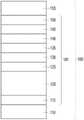
图1B是根据本发明的实施例的MTJ膜堆叠件的示意性截面图。Figure IB is a schematic cross-sectional view of an MTJ film stack according to an embodiment of the present invention.
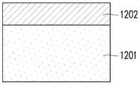
图2A、图2B和图2C示出根据本发明的实施例的MTJ膜堆叠件的磁性层的示意性截面图。2A , 2B and 2C show schematic cross-sectional views of magnetic layers of an MTJ film stack according to embodiments of the invention.
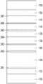
图3是根据本发明的另一实施例的MTJ膜堆叠件的示意性截面图。3 is a schematic cross-sectional view of an MTJ film stack according to another embodiment of the present invention.
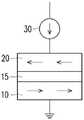
图4A和图4B示出MTJ单元的存储操作。4A and 4B illustrate the memory operation of the MTJ cell.
图4C和图4D示出MTJ单元的存储操作。4C and 4D illustrate the memory operation of the MTJ cell.
图5示出MRAM阵列。Figure 5 shows an MRAM array.
图6A、图6B和图6C示出根据本发明的实施例的包括MRAM的半导体器件的顺序制造工艺的各个阶段。6A , 6B and 6C illustrate various stages of a sequential manufacturing process of a semiconductor device including an MRAM according to an embodiment of the present invention.
图7A和图7B示出根据本发明的实施例的包括MRAM的半导体器件的顺序制造工艺的各个阶段。7A and 7B illustrate various stages of a sequential manufacturing process of a semiconductor device including an MRAM according to an embodiment of the present invention.
图8A和图8B示出根据本发明的实施例的包括MRAM的半导体器件的顺序制造工艺的各个阶段。8A and 8B illustrate various stages of a sequential manufacturing process of a semiconductor device including an MRAM according to an embodiment of the present invention.
图9A和图9B示出根据本发明的实施例的包括MRAM的半导体器件的顺序制造工艺的各个阶段。9A and 9B illustrate various stages of a sequential manufacturing process of a semiconductor device including an MRAM according to an embodiment of the present invention.
具体实施方式Detailed ways
应该理解的是,以下公开内容提供了用于实现本发明的不同特征的许多不同实施例或实例。下面描述了组件和布置的特定实施例或实例以简化本发明。当然,这些仅仅是实例,而不旨在限制本发明。例如,元件的尺寸不限于所公开的范围或数值,而是可以取决于工艺条件和/或器件的期望特性。此外,在以下描述中,在第二部件上方或者上形成第一部件可以包括第一部件和第二部件以直接接触的方式形成的实施例,并且也可以包括插入在第一部件和第二部件之间可以形成额外的部件,从而使得第一部件和第二部件可以不直接接触的实施例。为了简单和清楚起见,各种部件可以以不同比例任意地绘制。在附图中,为了简化的目的,可以省略一些层/部件。It should be understood that the following disclosure provides many different embodiments or examples for implementing different features of the invention. Specific embodiments or examples of components and arrangements are described below to simplify the present disclosure. Of course, these are examples only and are not intended to limit the invention. For example, the dimensions of the elements are not limited to the disclosed ranges or values, but may depend on process conditions and/or desired characteristics of the device. In addition, in the following description, forming a first part over or on a second part may include an embodiment in which the first part and the second part are formed in direct contact, and may also include an embodiment in which the first part and the second part are interposed. An additional component may be formed therebetween such that the first component and the second component may not be in direct contact. Various features may be arbitrarily drawn in different scales for simplicity and clarity. In the drawings, some layers/components may be omitted for simplicity.
此外,为了便于描述,在此可以使用诸如“在…下方”、“在…之下”、“下部”、“在…之上”、“上部”等空间相对术语以描述如图所示的一个元件或部件与另一个(或另一些)元件或部件的关系。除了图中所示的方位外,空间相对术语旨在包括器件在使用或操作中的不同方位。装置可以以其他方式定向(旋转90度或在其他方位上),并且在此使用的空间相对描述符可以同样地作出相应的解释。此外,术语“由...制成”可以表示“包括”或“由......组成”。此外,在以下制造工艺中,在所描述的操作中/之间可以存在一个或多个附加操作,并且操作顺序可以被改变。在本发明中,短语“A、B和C中的一个”意味着“A、B和/或C”(A,B,C,A和B,A和C,B和C,或A、B和C),并且除非另有说明,短语“A、B和C中的一个”并不意味着来自A的一个元件、来自B的一个元件和来自C的一个元件。In addition, for ease of description, spatially relative terms such as "under", "beneath", "lower", "above", "upper", etc. may be used herein to describe an The relationship of an element or component to another (or other) elements or components. Spatially relative terms are intended to encompass different orientations of the device in use or operation in addition to the orientation depicted in the figures. The device may be otherwise oriented (rotated 90 degrees or at other orientations) and the spatially relative descriptors used herein should likewise be interpreted accordingly. Furthermore, the term "consisting of" can mean "comprising" or "consisting of". Also, in the following manufacturing processes, there may be one or more additional operations in/between the described operations, and the order of operations may be changed. In the present invention, the phrase "one of A, B and C" means "A, B and/or C" (A, B, C, A and B, A and C, B and C, or A, B and C), and unless otherwise stated, the phrase "one of A, B, and C" does not mean an element from A, an element from B, and an element from C.
MRAM单元包括含有磁性层的多个层的膜堆叠件。在一些MRAM器件中,根据磁性设计,可能需要在磁性层之间插入一个或多个非磁性间隔层以优化磁性相互作用。MRAM单元的膜堆叠件经常遭受不利的扩散问题,其中来自晶种层和/或间隔层的金属扩散到MTJ的功能层中,从而对磁性隧道功能造成不利影响。根据膜堆叠件设计中扩散问题的严重性,可能需要将一个或多个扩散阻挡层插入膜堆叠件中以使不利的扩散现象最小化。此外,在MTJMRAM单元中,除了隧穿阻挡层之外,膜堆叠件内的每一层都需要导电以最大化读/写窗口。An MRAM cell includes a film stack of multiple layers including magnetic layers. In some MRAM devices, depending on the magnetic design, it may be necessary to insert one or more non-magnetic spacer layers between the magnetic layers to optimize the magnetic interaction. Membrane stacks of MRAM cells often suffer from adverse diffusion problems, where metal from the seed layer and/or spacer layer diffuses into the functional layers of the MTJ, adversely affecting the magnetic tunneling functionality. Depending on the severity of diffusion problems in the membrane stack design, one or more diffusion barrier layers may need to be inserted into the membrane stack to minimize adverse diffusion phenomena. Furthermore, in MTJMRAM cells, every layer within the film stack needs to be conductive, except the tunneling barrier layer, to maximize the read/write window.
在这些要求下,重要的是适当地选择能够提供期望的特定晶体结构和取向并且不会破坏功能层的磁性相互作用的晶种层、间隔层和/或扩散阻挡层的材料。此外,晶种层、间隔层和扩散阻挡层应该是光滑的、无取向特性(无定形的)、导电的和非磁性的。Under these requirements, it is important to properly select the materials of the seed layer, spacer layer and/or diffusion barrier layer that can provide the desired specific crystal structure and orientation without disrupting the magnetic interactions of the functional layers. In addition, the seed layer, spacer layer and diffusion barrier layer should be smooth, non-orientated (amorphous), conductive and non-magnetic.
MTJ MRAM单元的磁性隧道功能取决于MTJ膜的特定的晶体结构和取向。为了在MTJ膜中具有所需的晶体结构和取向,整个膜堆叠件需要在光滑的、无定形、导电非磁性晶种层上生长。在各种材料中,钽(Ta)最广泛地用作晶种层,钽(Ta)可以容易地生长为光滑且无定形的层。但是,Ta容易扩散到MTJ膜中,对磁性隧穿功能造成不利影响。此外,在MTJ膜中经常使用诸如钼(Mo)的非磁性间隔层,但Mo膜也表现出其他的扩散问题。The magnetic tunneling function of an MTJ MRAM cell depends on the specific crystal structure and orientation of the MTJ film. In order to have the desired crystal structure and orientation in the MTJ film, the entire film stack needs to be grown on a smooth, amorphous, conductive, non-magnetic seed layer. Among various materials, tantalum (Ta) is most widely used as a seed layer, and tantalum (Ta) can be easily grown as a smooth and amorphous layer. However, Ta easily diffuses into the MTJ film, which adversely affects the magnetic tunneling function. In addition, non-magnetic spacers such as molybdenum (Mo) are often used in MTJ films, but Mo films also exhibit other diffusion problems.
除了钽(Ta)和钼(Mo)之外,钴(Co)、铂(Pt)和/或镍(Ni)可以用作晶种层或间隔层,但是它们也扩散到MTJ膜的隧穿阻挡层中,隧穿阻挡层是金属氧化物层(例如,MgO)。而且,Ta可以与氧化层内部的氧反应,引起金属氧化物晶体结构和取向从期望状态变化。扩散原子插入MgO晶格中也会增加其应力,这可能导致MgO晶格质量随热老化而劣化。In addition to tantalum (Ta) and molybdenum (Mo), cobalt (Co), platinum (Pt), and/or nickel (Ni) can be used as seed or spacer layers, but they also diffuse into the tunneling barrier of the MTJ film Among layers, the tunneling barrier layer is a metal oxide layer (eg, MgO). Also, Ta can react with oxygen inside the oxide layer, causing the metal oxide crystal structure and orientation to change from a desired state. The insertion of diffusing atoms into the MgO lattice also increases its stress, which may lead to the deterioration of the MgO lattice quality with thermal aging.
晶体磁性层从MgO层的晶格生长,或者将其用作生长模板。因此,Ta、Mo、Co、Pt、Ni和其他晶种或间隔层材料扩散到MTJ的隧穿阻挡层中也防止了相邻的磁性金属层达到其期望的晶体结构和取向。The crystalline magnetic layer is grown from the lattice of the MgO layer, or it is used as a growth template. Thus, diffusion of Ta, Mo, Co, Pt, Ni, and other seed or spacer layer materials into the tunneling barrier of the MTJ also prevents the adjacent magnetic metal layer from reaching its desired crystal structure and orientation.
在本发明中,在磁性随机存取存储器的存储单元中,存储单元包括多个层的膜堆叠件,并且多个层中的至少一个包括铱。更具体地,晶种层、间隔层和扩散阻挡层中的至少一个包括铱。In the present invention, in a memory cell of a magnetic random access memory, the memory cell includes a film stack of a plurality of layers, and at least one of the layers includes iridium. More specifically, at least one of the seed layer, the spacer layer, and the diffusion barrier layer includes iridium.
图1A是根据本发明的实施例的MTJ MRAM单元的示意图。MTJ膜堆叠件100设置在半导体器件的下金属层Mx和上金属层My之间。金属层Mx和My用于将一个元件连接至形成在衬底上方不同层级处的半导体器件中的另一元件。此外,下金属层Mx连接至开关器件SW,该开关器件SW可以由MOSFET形成,该MOSFET包括但不限于平面型MOSFET、鳍式FET、全环绕栅极(GAA)FET、或任何其他开关器件。开关器件的控制端子(例如,FET的栅极端子)连接至字线。在一些实施例中,开关器件SW的端子中的一个连接至下金属层Mx,而另一端子连接至源极线,该源极线是固定电势(例如,地电势)。上金属层My连接至位线。在一些实施例中,开关器件SW设置在上金属层My和位线之间。FIG. 1A is a schematic diagram of an MTJ MRAM cell according to an embodiment of the present invention. The MTJ
MTJ膜堆叠件100包括连接至下金属层Mx的第一电极层110和连接至上金属层My的第二电极层155。如图1B所示,MTJ功能层101设置在第一电极层110和第二电极层155之间。The
MTJ功能层101包括第二钉扎(pinned)磁性层130、自由磁性层140以及由非磁性材料制成并且设置在第二钉扎磁性层130与自由磁性层140之间的隧穿阻挡层135。自由磁性层140和第二钉扎磁性层130分别包括可以磁性定向的一个或多个铁磁材料。自由磁性层140被配置为使得磁性定向可以通过暴露于外部磁场而改变或旋转。第二钉扎磁性层130被配置为使得磁性定向是固定的并且将不响应于典型的磁场。在一些实施例中,自由磁性层140的厚度在从约0.8nm至约1.5nm的范围内。在一些实施例中,第二钉扎层130的厚度在从约0.8nm至约2.0nm的范围内。The MTJ
隧穿阻挡层135包括能够在低电势下将自由磁性层140与第二钉扎磁性层130电隔离并且能够在较高电势下通过电子隧穿传导电流的相对薄的氧化物层。在一些实施例中,隧穿阻挡层135由氧化镁(MgO)制成,MgO的厚度在从约0.5nm至约1.2nm的范围内。The
如图1B所示,MTJ功能层101还包括反铁磁层125。反铁磁层125用于固定第二钉扎磁性层130的磁取向。反铁磁层125包括钌(Ru)或任何其他合适的反铁磁材料。在一些实施例中,反铁磁层125的厚度在从约0.4nm至约1.0nm的范围内。As shown in FIG. 1B , the MTJ
如图1B所示,MTJ功能层101还包括第一钉扎磁性层120,第一钉扎磁性层120包括一种或多种磁性材料。As shown in FIG. 1B , the MTJ
第二钉扎磁性层130包括多层磁性材料。在一些实施例中,如图2A所示,第二钉扎磁性层130包括四层1301、1302、1303和1304,其中层1304与隧穿阻挡层135接触并且层1301与反铁磁层125接触。在一些实施例中,层1301(最底层)包括钴(Co)和铂(Pt)的多层结构。在一些实施例中,钴层的厚度在从约0.3nm至约0.6nm的范围内,并且铂层的厚度在从约0.2nm至约0.5nm的范围内。钴层的厚度可以与铂层相同或比铂层更大。在一些实施例中,钴层和铂层交替地堆叠,使得层1301的总厚度在从约2.0nm至约5.0nm的范围内。层1302包括钴层,钴层的厚度在从约0.4nm至约0.6nm的范围内。在某些实施例中,层1301是钴层并且层1302是如上所述的钴层和铂层的多层。在本发明中,“元素”层通常意味着“元素”的含量大于99%。The second pinned
层1303是间隔层。在一些实施例中,间隔层1303的厚度在从约0.2nm至约0.5nm的范围内。层1304是钴铁硼(CoFeB)层、钴/钯(CoPd)层和/或钴铁(CoFe)层。
在一些实施例中,层1304的厚度在从约0.8nm至约1.5nm的范围内。In some embodiments,
第一钉扎磁性层120包括多层磁性材料。在一些实施例中,如图2B所示,第一钉扎磁性层120包括两层1201和1202,其中层1202与反铁磁层125接触。在一些实施例中,层1201包括钴(Co)和铂(Pt)的多层结构。在一些实施例中,钴层的厚度在从约0.3nm至约0.6nm的范围内,并且铂层的厚度在从约0.2nm至约0.5nm的范围内。钴层的厚度可以与铂层相同或比铂层更大。在一些实施例中,钴层和铂层交替地堆叠,使得层1201的总厚度在从约5.0nm至约10.0nm的范围内。层1202包括钴层,钴层的厚度在从约0.4nm至约0.6nm的范围内。The first pinned
在一些实施例中,自由磁性层140包括厚度在从约1.0nm至约2.0nm范围内的钴铁硼(CoFeB)层、钴/钯(CoPd)层和/或钴铁(CoFe)层。在其他实施例中,自由磁性层140包括多层磁性材料。在一些实施例中,如图2C所示,自由磁性层140包括三层1401、1402和1403,其中层1401与隧穿阻挡层135接触。在一些实施例中,层1401和1403是厚度在从约1.0nm至约2.0nm的范围内的钴铁硼(CoFeB)层、钴/钯(CoPd)层和/或钴铁(CoFe)层。层1402是间隔层。在一些实施例中,间隔层1402的厚度在从约0.2nm至约0.6nm的范围内。In some embodiments, the free
如图1B所示,MTJ功能层101还包括在第一电极层110上形成的晶种层115、在自由磁性层140上形成的覆盖层145、在覆盖层145上形成的扩散阻挡层150。在一些实施例中,覆盖层145由诸如氧化镁或氧化铝的介电材料制成,并且其厚度在从约0.5nm至约1.5nm的范围内。第一电极层110由诸如金属的导电材料制成,以降低第一钉扎磁性层120的电阻,特别是用于编程。第二电极层155也由诸如金属的导电材料制成以降低读取期间的电阻率。As shown in FIG. 1B , the MTJ
在本实施例中,第一电极层110、晶种层115、扩散阻挡层150、第二电极层155、间隔层1303和间隔层1402中的至少一个包括铱(Ir)。在某些实施例中,第一电极层110、晶种层115、扩散阻挡层150和第二电极层155中的至少一个包括铱(Ir)。含铱层可以是从由铱层、氧化铱层、铱层和氧化铱层的双层结构、铱-钛氮化物层、铱层和钽层的双层结构、以及铱和钽的二元合金层组成的组中选择的一个。In this embodiment, at least one of the
这些含铱材料具有独特的特征。例如,铱以及铱和钽的二元合金具有形成超平滑表面形态的自然趋势、具有非常高的导电性并且是非磁性的。此外,铱以及铱和钽的二元合金可以形成为非晶层。此外,铱-钽低氧化物是具有实质导电性的导体或半导体。氧化铱是导电且致密的材料,并且即使形成为薄层(例如,小于1.0nm)也具有高扩散阻挡性能。此外,铱层和/或氧化铱层可以容易地集成到半导体CMOS工艺中。此外,含铱材料通常具有稳定的化学和物理性质、具有化学惰性且耐腐蚀。These iridium-containing materials have unique characteristics. For example, iridium and binary alloys of iridium and tantalum have a natural tendency to form ultra-smooth surface morphology, are very electrically conductive, and are nonmagnetic. In addition, iridium and binary alloys of iridium and tantalum can be formed as amorphous layers. In addition, iridium-tantalum suboxide is a conductor or semiconductor having substantial conductivity. Iridium oxide is a conductive and dense material, and has high diffusion barrier properties even when formed in a thin layer (eg, less than 1.0 nm). Furthermore, the iridium layer and/or the iridium oxide layer can be easily integrated into a semiconductor CMOS process. In addition, iridium-containing materials are generally chemically and physically stable, chemically inert, and corrosion-resistant.
在一些实施例中,晶种层115包括铱层和/或铱和钽的二元合金层。晶种层115用于第一钉扎磁性层120的生长,并且通常需要具有光滑的表面形态、高电导率并且基本上没有扩散到钉扎磁性层120中,在一些实施例中,晶种层115的厚度在从约0.5nm至约20nm的范围内,并且在其他实施例中,晶种层115的厚度在从约1.0nm至约10nm的范围内。在一些实施例中,晶种层115是无定形的。In some embodiments, the
在一些实施例中,扩散阻挡层150包括铱层和/或铱和钽的二元合金层。用于MTJ膜堆叠件的扩散阻挡层通常需要具有超平滑表面形态和高电导率,并且对缓解扩散问题基本上有效。此外,扩散阻挡层还应该耐受低水平的氧化,而不会显著降低其电导率。在一些实施例中,扩散阻挡层150的厚度在从约0.1nm至约10nm的范围内,并且在其他实施例中,扩散阻挡层150的厚度在从约0.5nm至约5.0nm的范围内。In some embodiments, the
在一些实施例中,间隔层1303和/或间隔层1402包括铱层和/或铱和钽的二元合金层。通常需要用于MTJ膜堆叠件的间隔层具有超平滑表面形态和高电导率并且基本上没有扩散问题。此外,间隔层还应该耐受低水平的氧化,而不会显著降低其电导率。在一些实施例中,间隔层1303和/或1402的厚度在从约0.1nm至约10nm的范围内,并且在其他实施例中,间隔层1303和/或1402的厚度在从约0.5nm至约5.0nm的范围内。In some embodiments, the
在某些实施例中,包括上述含铱层的一个或多个附加扩散阻挡层和/或间隔层可以插入在第一电极层110、晶种层115、第一钉扎磁性层120、反铁磁层125、第二钉扎磁性层130、隧穿阻挡层135、自由磁性层140、覆盖层145、扩散阻挡层150和第二电极层155中的任意两个相邻的层之间。In certain embodiments, one or more additional diffusion barrier layers and/or spacer layers, including the iridium-containing layers described above, may be inserted between the
例如,在一些实施例中,如图3所示,在晶种层115和第一钉扎磁性层120之间插入间隔或阻挡层201。当晶种层115由钽(Ta)、钼(Mo)、钴(Co)、镍(Ni)、钌(Ru)和铂(Pt)中的一种或多种制成时,间隔或阻挡层201可以防止Ta、Mo、Co、Ni、Ru和/或Pt扩散到第一钉扎磁性层120中。在某些实施例中,间隔或阻挡层201包括从由铱层以及铱和钽的二元合金层组成的组中选择的至少一种。在一些实施例中,间隔或阻挡层201的厚度在从约0.1nm至约10nm的范围内,并且在其他实施例中,间隔或阻挡层201的厚度在从约0.5nm至约5.0nm的范围内。当晶种层115包括含铱层时,间隔或阻挡层201可能不是必需的。For example, in some embodiments, as shown in FIG. 3 , a spacer or
在一些实施例中,如图3所示,在第二钉扎磁性层130和隧穿阻挡层135之间插入间隔或阻挡层204。间隔或阻挡层204可以防止包括在第二钉扎磁性层130中的Co、Fe和/或Ta的扩散进入隧穿阻挡层135。在某些实施例中,间隔或阻挡层204包括从由铱层以及铱和钽的二元合金层组成的组中选择的至少一种。在一些实施例中,间隔或阻挡层204的厚度在从约0.1nm至约10nm的范围内,并且在其他实施例中,间隔或阻挡层204的厚度在从约0.5nm至约5.0nm的范围内。In some embodiments, as shown in FIG. 3 , a spacer or
类似地,在一些实施例中,间隔或阻挡层205插入在隧穿阻挡层135和自由磁性层140之间。间隔或阻挡层205可以防止包括在自由磁性层140中的Co、Fe和/或Ta扩散进入隧穿阻挡层135。在某些实施例中,间隔或阻挡层205包括从由铱层以及铱和钽的二元合金层组成的组中选择的至少一种。在一些实施例中,间隔或阻挡层205的厚度在从约0.1nm至约10nm的范围内,并且在其他实施例中,间隔或阻挡层205的厚度在从约0.5nm至约5.0nm的范围内。Similarly, in some embodiments, a spacer or
在一些实施例中,间隔或阻挡层206插入在自由磁性层140和覆盖层145之间。在某些实施例中,覆盖层145由氧化镁或氧化铝制成。间隔或阻挡层206可以防止包括在自由磁性层140中的Co、Fe和/或Ta扩散进入覆盖层145。在某些实施例中,间隔或阻挡层206包括从由铱层以及铱和钽的二元合金层组成的组中选择的至少一种。在一些实施例中,间隔或阻挡层206的厚度在从约0.1nm至约10nm的范围内,并且在其他实施例中,间隔或阻挡层206的厚度在从约0.5nm至约5.0nm的范围内。In some embodiments, a spacer or
在一些实施例中,间隔或阻挡层207插入在覆盖层145和扩散阻挡层150之间。在某些实施例中,扩散阻挡层150由钽或其他材料制成。间隔或阻挡层207可以防止包括在扩散阻挡层150中的Ta扩散进入覆盖层145。在某些实施例中,间隔或阻挡层207包括从由铱层以及铱和钽的二元合金层组成的组中选择的至少一种。在一些实施例中,间隔或阻挡层207的厚度在从约0.1nm至约10nm的范围内,并且在其他实施例中,间隔或阻挡层207的厚度在从约0.5nm至约5.0nm的范围内。当扩散阻挡层150包括含铱层时,间隔或阻挡层207可能不是必需的。In some embodiments, a spacer or
在其他实施例中,如图3所示,间隔或阻挡层202插入在第一钉扎磁性层120与反铁磁层125之间。在某些实施例中,间隔或阻挡层202包括从由铱层以及铱和钽的二元合金层组成的组中选择的至少一种。在一些实施例中,间隔或阻挡层202的厚度在从约0.1nm至约10nm的范围内,并且在其他实施例中,间隔或阻挡层202的厚度在从约0.5nm至约5.0nm的范围内。In other embodiments, as shown in FIG. 3 , a spacer or
在其他实施例中,如图3所示,间隔或阻挡层203插入在反铁磁层125与第二钉扎磁性层130之间。在某些实施例中,间隔或阻挡层203包括从由铱层以及铱和钽的二元合金层组成的组中选择的至少一种。在一些实施例中,间隔或阻挡层203的厚度在从约0.1nm至约10nm的范围内,并且在其他实施例中,间隔或阻挡层203的厚度在从约0.5nm至约5.0nm的范围内。In other embodiments, as shown in FIG. 3 , a spacer or
间隔或阻挡层202和203可以进一步防止可以包括在第一电极层110、晶种层115、第一钉扎磁性层120和/或反铁磁层125的Ta、Mo、Co、Ni、Ru和/或Pt扩散进入隧穿阻挡层135。Spacer or
在一些实施例中,第一电极层110和第二电极层155中的至少一个包括从由铱层、氧化铱层、铱层和氧化铱的双层结构、铱-钛氮化物层、以及铱和钽的二元合金层组成的组中选择的一种。第一电极层110形成在由诸如Cu、Al、W、Co、Ni和/或上述的合金制成的下金属层Mx上,并且由诸如Cu、Al、W、Co、Ni和/或上述的合金制成的上金属层My形成在第二电极层155上。当第一电极层110和第二电极层155不包括含铱层时,第一电极层110包括Ta、Pt、Au、Cr和TiN中的一种或多种,并且第二电极层155包括Ru、Au、Cr和Ta中的一种或多种。In some embodiments, at least one of the
可以通过物理汽相沉积(PVD)、分子束外延(MBE)、脉冲激光沉积(PLD)、原子层沉积(ALD)、电子束(e-beam)外延、化学汽相沉积(CVD)或衍生CVD工艺(还包括低压CVD(LPCVD)、超高真空CVD(UHVCVD)、减压CVD(RPCVD)或上述的任何组合)、或任何其他合适的膜沉积方法来形成含铱层。钉扎磁性层、自由磁性层和反铁磁层也可以通过CVD、PVD或ALD或任何其他合适的膜沉积方法形成。隧穿阻挡层也可以通过CVD、PVD或ALD或任何其他合适的膜沉积方法形成。第一和第二电极层也可以通过CVD、PVD、ALD或电镀或任何其他合适的膜沉积方法形成。Can be deposited by physical vapor deposition (PVD), molecular beam epitaxy (MBE), pulsed laser deposition (PLD), atomic layer deposition (ALD), electron beam (e-beam) epitaxy, chemical vapor deposition (CVD) or derivative CVD process (also including low pressure CVD (LPCVD), ultra high vacuum CVD (UHVCVD), reduced pressure CVD (RPCVD) or any combination thereof), or any other suitable film deposition method to form the iridium-containing layer. Pinned magnetic layers, free magnetic layers and antiferromagnetic layers can also be formed by CVD, PVD or ALD or any other suitable film deposition method. The tunneling barrier layer can also be formed by CVD, PVD or ALD or any other suitable film deposition method. The first and second electrode layers may also be formed by CVD, PVD, ALD or electroplating or any other suitable film deposition method.
在一些实施例中,第一电极层110形成在已经图案化的下金属层Mx上,晶种层115形成在第一电极层110上,第一钉扎磁性层120形成在晶种层115上,反铁磁层125形成在第一钉扎磁性层120上,第二钉扎磁性层130形成在反铁磁层125上,隧穿阻挡层135形成在第二钉扎磁性层130上,自由磁性层140形成在隧穿阻挡层135上,覆盖层145形成在自由磁性层140上,扩散阻挡层150形成在覆盖层145上,并且第二电极层155形成在扩散层150上。实施一个或多个光刻和蚀刻操作以将堆叠的层图案化为用于每个存储单元的MTJ膜堆叠件。在其他实施例中,用于存储单元的沟槽形成在介电层中,并且MTJ膜形成在沟槽中。In some embodiments, the
在一些实施例中,MRAM单元形成在设置在衬底上方的介电材料上方。在一些实施例中,衬底包括硅(Si)或其他合适的半导体材料。晶体管、驱动电路、逻辑电路或任何其他电子器件由半导体材料形成并与MRAM单元集成。In some embodiments, an MRAM cell is formed over a dielectric material disposed over a substrate. In some embodiments, the substrate includes silicon (Si) or other suitable semiconductor materials. Transistors, driver circuits, logic circuits or any other electronic devices are formed of semiconductor material and integrated with the MRAM cell.
图4A至图4D示出了MTJ单元的存储操作。如图4A至图4D所示,MTJ单元包括钉扎磁性层10、隧穿阻挡层15和自由磁性层20。钉扎磁性层10对应于第二钉扎磁性层130或图1B的第一钉扎磁性层120、反铁磁层125和第二钉扎磁性层130的组合。隧穿阻挡层15对应于图1B的隧穿阻挡层135,并且自由磁性层20对应于图1B的自由磁性层140。在图4A至图4D中,其余层被省略。电流源30串联连接至MTJ结构。4A to 4D illustrate the memory operation of the MTJ cell. As shown in FIGS. 4A to 4D , the MTJ cell includes a pinned
在图4A中,钉扎磁性层10和自由磁性层20在相反的方向上磁性地定向。在一些实施例中,钉扎磁性层10和自由磁性层20的自旋方向平行于膜堆叠件方向(垂直于膜的表面)。在图4B中,钉扎磁性层10和自由磁性层20在相同的方向上磁性地取向。在其他实施例中,钉扎磁性层10和自由磁性层20的自旋方向垂直于膜堆叠件方向(平行于膜的表面),如图4C和图4D所示。在图4C中,钉扎磁性层10和自由磁性层20在相反的方向上磁性地取向,而如图4D所示,钉扎磁性层10和自由磁性层20在相同的方向上磁性地定向。In FIG. 4A , the pinned
如果通过电流源30强制相同的电流值IC流过MTJ单元,则发现在图4A(或图4C)的情况下的单元电压V1大于图4B(或图4D)的情况下的单元电压V2,因为图4A(或图4C)所示的相反取向MTJ单元的电阻大于图4B(或图4D)所示的相同取向MTJ单元的电阻。二进制逻辑数据(“0”和“1”)可以存储在MTJ单元中,并且基于单元取向和所产生的电阻进行检索。此外,由于所存储的数据不需要存储能量源,所以该单元是非易失性的。If the same current valueIC is forced to flow through the MTJ cell by the
图5示出MRAM阵列50。每个存储单元均包括MTJ单元Mc和晶体管Tr,例如MOSFET。晶体管Tr的栅极连接至字线WL,并且晶体管Tr的漏极(或源极)连接至MTJ单元Mc的一端,并且MTJ单元的另一端连接至位线BL。此外,用于编程的信号线PL被设置为与MTJ单元相邻。FIG. 5 shows an
通过使能(asserting)该单元的字线来读取存储单元,强制读取电流通过该单元的位线BL,并且然后测量该位线BL上的电压。例如,为了读取目标MTJ单元的状态,字线WL被使能以导通晶体管Tr。目标MTJ单元的自由磁性层由此通过晶体管Tr连接至固定电势SL,例如地电势。接下来,在位线BL上强制施加读取电流。由于只有给定的读取晶体管Tr导通,所以读取电流流过目标MTJ单元到地电势。然后测量位线BL的电压以确定目标MTJ单元的状态(“0”或“1”)。在一些实施例中,如图5所示,每个MTJ单元均具有一个读取晶体管Tr。因此,这种类型的MRAM架构被称为1T1R。在其他实施例中,将两个晶体管分配至一个MTJ单元,形成2T1R系统。可以采用其他单元阵列配置。A memory cell is read by asserting the word line of the cell, forcing a read current through the bit line BL of the cell, and then measuring the voltage on the bit line BL. For example, to read the state of the target MTJ cell, the word line WL is enabled to turn on the transistor Tr. The free magnetic layer of the target MTJ cell is thus connected via the transistor Tr to a fixed potential SL, eg ground potential. Next, a read current is forcibly applied to the bit line BL. Since only a given read transistor Tr is turned on, a read current flows through the target MTJ cell to ground potential. The voltage of the bit line BL is then measured to determine the state of the target MTJ cell ("0" or "1"). In some embodiments, as shown in FIG. 5 , each MTJ unit has a read transistor Tr. Hence, this type of MRAM architecture is called 1T1R. In other embodiments, two transistors are assigned to one MTJ cell, forming a 2T1R system. Other cell array configurations may be used.
图6A至图9B示出根据本发明的实施例的包括MRAM的半导体器件的顺序制造工艺的各个阶段。应该理解的是,可以在图6A至图9B所示的工艺之前、期间和之后提供附加的操作,并且对于该方法的附加实施例,下面描述的一些操作可以被替换或消除。在下面的实施例中可以采用的材料、构造、尺寸和/或工艺与前面用图1A至图5描述的实施例相同或类似,并且可以省略其详细说明。6A to 9B illustrate various stages of a sequential manufacturing process of a semiconductor device including an MRAM according to an embodiment of the present invention. It should be understood that additional operations may be provided before, during, and after the processes shown in FIGS. 6A-9B , and that some of the operations described below may be replaced or eliminated for additional embodiments of the method. Materials, configurations, dimensions, and/or processes that may be employed in the following embodiments are the same as or similar to those described above with FIGS. 1A to 5 , and detailed description thereof may be omitted.
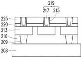
如图6A所示,在衬底208上方的第一ILD层210中形成下金属线213。在一些实施例中,通孔接触件209设置在下金属线213下方。然后,如图6B所示,在图6A的结构上方形成第一绝缘层220作为蚀刻停止层,并且在第一绝缘层220上方形成第二ILD层225。此外,如图6B所示,通过使用一个或多个光刻和蚀刻操作来形成通孔接触件开口222以暴露下金属线213的上表面。随后,如图6C所示,形成包括层215和217的通孔接触件219。实施一个或多个成膜操作,例如包括溅射、ALD、化学电镀和/或电镀的CVD、PVD,并且实施诸如CMP的平坦化操作以制造通孔接触件219。As shown in FIG. 6A , a
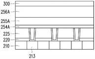
然后,如图7A所示,依次形成用于底部电极254的第一导电层254A、用于MTJ膜堆叠件255的堆叠层255A和用于顶部电极256的第二导电层256A。在一些实施例中,用于硬掩模的层300还形成在第二导电层256A上。Then, as shown in FIG. 7A , a first conductive layer 254A for the
如上所述,第一导电层254A和/或用于MTJ膜堆叠件255的堆叠层255A中的一层或多层包括铱层、铱层和氧化铱层的双层结构、铱-钛氮化物层、铱层和钽层的双层结构以及铱和钽的二元合金层中的一个。层254A、255A和256A可以通过物理汽相沉积(PVD)(包括溅射、分子束外延(MBE)、脉冲激光沉积(PLD)、原子层沉积(ALD)、电子束(e-beam)外延)、化学汽相沉积(CVD)或衍生CVD工艺(还包括低压CVD(LPCVD)、超高真空CVD(UHVCVD)、减压CVD(RPCVD))、电镀或上述的任何组合、或任何其他合适的膜沉积方法来形成。As described above, the first conductive layer 254A and/or one or more layers in the
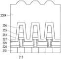
如图7B所示,通过使用一个或多个光刻和蚀刻操作,图7A所示的膜堆叠件被图案化为MRAM单元结构,MRAM单元结构包括底部电极254、MTJ膜堆叠件255和顶部电极256。在一些实施例中,在图案化第二导电层256A、堆叠层255A和第一导电层254A之后,第二ILD层225被部分地凹陷。在一些实施例中,凹陷的量D1在从约1nm至约30nm的范围内。As shown in FIG. 7B, by using one or more photolithography and etching operations, the film stack shown in FIG. 7A is patterned into an MRAM cell structure comprising a
随后,如图8A所示,形成侧壁间隔层227以覆盖MRAM单元结构。侧壁间隔层227可以通过CVD、PVD或ALD或任何其他合适的膜沉积方法形成。在一些实施例中,通过CVD、PVD或ALD在小于约150℃的较低温度范围(例如,从约100℃至约150℃的范围内)下形成侧壁间隔层227。当在较高的温度(例如,从约200℃至约300℃(或更高)的范围内)下形成侧壁间隔层227时,成膜工艺可能会损坏MTJ膜堆叠件255。如图8A所示,侧壁间隔层227被共形地形成。在一些实施例中,侧壁间隔层227包括多层不同的绝缘材料。Subsequently, as shown in FIG. 8A, a
接下来,如图8B所示,形成用于第三ILD层230的介电材料层230A以完全覆盖侧壁间隔层227。在一些实施例中,作为平坦化操作,对介电材料层230A实施回蚀刻操作,并且然后实施CMP操作。Next, as shown in FIG. 8B , a
随后,如图9A所示,在平坦化操作之后形成包括第一介电层235、第二介电层237和第三介电层240的第四ILD层。第四ILD层的介电层可以通过CVD、PVD或ALD或其他合适的成膜方法形成。在一些实施例中,通过诸如CVD、可流动CVD(FCVD)或旋涂玻璃工艺的工艺来形成第三介电层240,但是可以使用任何可接受的工艺。随后,实施平坦化工艺,例如化学机械抛光(CMP)和/或回蚀刻工艺等。Subsequently, as shown in FIG. 9A , a fourth ILD layer including the
然后,如图9B所示,通过使用一个或多个光刻和蚀刻操作来形成接触件开口,并且接触件开口填充有导电材料,以形成接触暴露的顶部电极256的导电接触件245。Then, as shown in FIG. 9B , contact openings are formed using one or more photolithography and etching operations and filled with a conductive material to form
应该理解的是,图9B所示的器件经历进一步的半导体工艺以形成各种部件,例如互连金属层、介电层、钝化层等。It should be understood that the device shown in FIG. 9B undergoes further semiconductor processing to form various features such as interconnect metal layers, dielectric layers, passivation layers, and the like.
将会理解的是,并非所有的优点都必须在本文中讨论,对于所有实施例或实例都不需要特别的优点,并且其他实施例或实例可以提供不同的优点。It will be appreciated that not all advantages must be discussed herein, that no particular advantage is required for all embodiments or examples, and that other embodiments or examples may provide different advantages.
例如,在本发明中,由于一个或多个含铱层用于或插入在磁性隧道结型MRAM单元中,可以防止金属元素从晶种层、钉扎磁性层、自由磁性层、反铁磁层和/或电极层扩散到隧穿阻挡层中。此外,由于含铱层具有光滑的表面形态,所以含铱晶种层可以改善形成于其上的钉扎磁性层的特性。For example, in the present invention, since one or more iridium-containing layers are used or inserted in the magnetic tunnel junction MRAM cell, metal elements can be prevented from and/or the electrode layer diffuses into the tunneling barrier layer. Furthermore, since the iridium-containing layer has a smooth surface morphology, the iridium-containing seed layer can improve the characteristics of the pinned magnetic layer formed thereon.
根据本发明的一方面,磁性随机存取存储器的存储单元包括设置在第一金属层与第二金属层之间的多层。多层中的至少一层包括从由铱层、铱层和氧化铱层的双层结构、铱-钛氮化物层、铱层和钽层的双层结构、以及铱和钽的二元合金层组成的组中选择的一种。在上述和下述实施例中的一个或多个中,多层包括由第一导电材料制成的第一电极层和由第二导电层制成的第二电极层,多层中的剩余层布置在第一电极层与第二电极层之间。在上述和下述实施例中的一个或多个中,第一电极层和第二电极层中的至少一个包括铱。在上述和下述实施例中的一个或多个中,第一电极层和第二电极层中的至少一个包括从由铱层和氧化铱层的双层结构、铱-钛氮化物层、铱层和钽层的双层结构、以及铱和钽的二元合金层组成的组中选择的一种。在上述和下述实施例中的一个或多个中,多层包括设置在第一电极层上方的晶种层,并且晶种层包括从由铱层、铱层和钽层的双层结构、以及铱和钽的二元合金层组成的组中选择的至少一种。在上述和下述实施例中的一个或多个中,多层包括设置在晶种层上方的钉扎磁性层、由非磁性材料制成并且设置在钉扎磁性层上方的隧穿阻挡层、设置在隧穿阻挡层上方的自由磁性层、以及设置在自由磁性层上方的扩散阻挡层,并且扩散阻挡层包括从由铱层、铱层和钽层的双层结构、以及铱和钽的二元合金层组成的组中选择的至少一种。在上述和下述实施例中的一个或多个中,钉扎磁性层包括第一磁性层和第二磁性层以及设置在第一磁性层与第二磁性层之间的反铁磁层。在上述和下述实施例中的一个或多个中,多层还包括由非磁性材料制成并且设置在自由磁性层与扩散阻挡层之间的覆盖层。在上述和下述实施例中的一个或多个中,隧穿阻挡层和覆盖层由氧化镁制成。According to an aspect of the present invention, a memory cell of a magnetic random access memory includes multiple layers disposed between a first metal layer and a second metal layer. At least one of the multilayers comprises an iridium layer, a double-layer structure of an iridium layer and an iridium oxide layer, a double-layer structure of an iridium-titanium nitride layer, an iridium layer and a tantalum layer, and a binary alloy layer of iridium and tantalum One selected from the group consisting of. In one or more of the above and following embodiments, the multilayer includes a first electrode layer made of a first conductive material and a second electrode layer made of a second conductive layer, and the remaining layers in the multilayer Arranged between the first electrode layer and the second electrode layer. In one or more of the above and below-described embodiments, at least one of the first electrode layer and the second electrode layer includes iridium. In one or more of the above and following embodiments, at least one of the first electrode layer and the second electrode layer comprises a double-layer structure consisting of an iridium layer and an iridium oxide layer, an iridium-titanium nitride layer, an iridium One selected from the group consisting of a double-layer structure of a layer and a tantalum layer, and a binary alloy layer of iridium and tantalum. In one or more of the above and following embodiments, the multilayer includes a seed layer disposed above the first electrode layer, and the seed layer includes a bilayer structure consisting of an iridium layer, an iridium layer and a tantalum layer, And at least one selected from the group consisting of a binary alloy layer of iridium and tantalum. In one or more of the above and following embodiments, the multilayer includes a pinned magnetic layer disposed over the seed layer, a tunneling barrier layer made of a non-magnetic material disposed over the pinned magnetic layer, The free magnetic layer disposed above the tunneling barrier layer, and the diffusion barrier layer disposed above the free magnetic layer, and the diffusion barrier layer includes an iridium layer, a double-layer structure of an iridium layer and a tantalum layer, and a dual layer of iridium and tantalum. At least one selected from the group consisting of elemental alloy layers. In one or more of the embodiments above and below, the pinned magnetic layer includes a first magnetic layer and a second magnetic layer, and an antiferromagnetic layer disposed between the first magnetic layer and the second magnetic layer. In one or more of the above and below embodiments, the multilayer further includes a cover layer made of a non-magnetic material and disposed between the free magnetic layer and the diffusion barrier layer. In one or more of the embodiments above and below, the tunneling barrier layer and the cover layer are made of magnesium oxide.
根据本发明的另一方面,磁性随机存取存储器的存储单元包括多层。多层包括第一电极层、设置在第一电极层上方的晶种层、设置在晶种层上方的第一钉扎磁性层、设置在第一钉扎磁性层上方的反铁磁层、设置在反铁磁层上方的第二钉扎磁性层、由非磁性材料制成并且设置在第二钉扎磁性层上方的隧穿阻挡层、设置在隧穿阻挡层上方的自由磁性层、由非磁性材料制成并且设置在自由磁性层上方的覆盖层、设置在覆盖层上方的扩散阻挡层以及设置在扩散层上方的第二电极层。包含铱的含铱层中的至少一个设置在从晶种层到扩散阻挡层的任何相邻两层之间。在上述和下述实施例中的一个或多个中,含铱层中的至少一个具有从0.1nm至5.0nm范围内的厚度。在上述和下述实施例中的一个或多个中,从晶种层到扩散阻挡层的层不含铱。According to another aspect of the present invention, a memory cell of a magnetic random access memory includes multiple layers. The multilayer includes a first electrode layer, a seed layer disposed above the first electrode layer, a first pinned magnetic layer disposed above the seed layer, an antiferromagnetic layer disposed above the first pinned magnetic layer, an A second pinned magnetic layer above the antiferromagnetic layer, a tunnel barrier layer made of a nonmagnetic material and disposed above the second pinned magnetic layer, a free magnetic layer disposed above the tunnel barrier layer, A covering layer made of magnetic material and arranged above the free magnetic layer, a diffusion barrier layer arranged above the covering layer, and a second electrode layer arranged above the diffusion layer. At least one of the iridium-containing layers containing iridium is disposed between any adjacent two layers from the seed layer to the diffusion barrier layer. In one or more of the above and following embodiments, at least one of the iridium-containing layers has a thickness ranging from 0.1 nm to 5.0 nm. In one or more of the embodiments above and below, the layer from the seed layer to the diffusion barrier layer is free of iridium.
根据本发明的另一方面,半导体器件包括具有多个磁性存储单元的磁性随机存取存储器(MRAM)。磁性存储单元中的每一个均包括设置在第一金属层与第二金属层之间的多层。多层中的至少一层包括从由铱层、铱层和氧化铱层的双层结构、铱-钛氮化物层、铱层和钽层的双层结构、以及铱和钽的二元合金层组成的组中选择的一种。在上述和下述实施例中的一个或多个中,多层包括由第一导电材料制成的第一电极层和由第二导电层制成的第二电极层,多层中的剩余层设置在第一电极层与第二电极层之间,并且第一电极层和第二电极层中的至少一个包括从由铱层、铱层和氧化铱层的双层结构、铱-钛氮化物层、铱层和钽层的双层结构、以及铱和钽的二元合金层组成的组中选择的至少一种。在上述和下述实施例中的一个或多个中,多层包括由第一导电材料制成的第一电极层和由第二导电层制成的第二电极层,多层中的剩余层设置在第一电极层与第二电极层之间,剩余层包括设置在第一电极层上方的晶种层,并且晶种层包括从由铱层、铱层和钽层的双层结构、以及铱和钽的二元合金层组成的组中选择的至少一种。在上述和下述实施例中的一个或多个中,多层包括由第一导电材料制成的第一电极层和由第二导电层制成的第二电极层,多层中的剩余层设置在第一电极层与第二电极层之间,剩余层包括设置在第一电极层上方的晶种层和设置在晶种层上方的钉扎磁性层、设置在钉扎磁性层上方的隧穿阻挡层、设置在隧穿阻挡层上方的自由磁性层、以及设置在自由磁性层上方的扩散阻挡层,并且扩散阻挡层包括从由铱层、铱层和钽层的双层结构、以及铱和钽的二元合金层组成的组中的选择的至少一种。在上述和下述实施例中的一个或多个中,钉扎磁性层包括第一磁性层和第二磁性层以及设置在第一磁性层与第二磁性层之间的反铁磁层。在上述和下述实施例中的一个或多个中,多层还包括设置在自由磁性层与扩散阻挡层之间的覆盖层。在上述和下述实施例中的一个或多个中,多层包括第一电极层、设置在第一电极层上方的晶种层、设置在晶种层上方的第一钉扎磁性层、设置在第一钉扎磁性层上方的反铁磁层、设置在反铁磁层上方的第二钉扎磁性层、由非磁性材料制成并且设置在第二钉扎磁性层上方的隧穿阻挡层、设置在隧穿阻挡层上方的自由磁性层、由非磁性材料制成并且设置在自由磁性层上方的覆盖层、设置在覆盖层上方的扩散阻挡层以及设置在扩散阻挡层上方的第二电极层,并且包含铱的含铱层中的至少一个设置在从晶种层到扩散阻挡层的任何相邻两层之间。According to another aspect of the present invention, a semiconductor device includes a magnetic random access memory (MRAM) having a plurality of magnetic memory cells. Each of the magnetic memory cells includes multiple layers disposed between a first metal layer and a second metal layer. At least one of the multilayers comprises an iridium layer, a double-layer structure of an iridium layer and an iridium oxide layer, a double-layer structure of an iridium-titanium nitride layer, an iridium layer and a tantalum layer, and a binary alloy layer of iridium and tantalum One selected from the group consisting of. In one or more of the above and following embodiments, the multilayer includes a first electrode layer made of a first conductive material and a second electrode layer made of a second conductive layer, and the remaining layers in the multilayer It is arranged between the first electrode layer and the second electrode layer, and at least one of the first electrode layer and the second electrode layer comprises a double-layer structure consisting of an iridium layer, an iridium layer and an iridium oxide layer, an iridium-titanium nitride At least one selected from the group consisting of a double-layer structure of an iridium layer and a tantalum layer, and a binary alloy layer of iridium and tantalum. In one or more of the above and following embodiments, the multilayer includes a first electrode layer made of a first conductive material and a second electrode layer made of a second conductive layer, and the remaining layers in the multilayer disposed between the first electrode layer and the second electrode layer, the remaining layer comprises a seed layer disposed above the first electrode layer, and the seed layer comprises a double-layer structure consisting of an iridium layer, an iridium layer and a tantalum layer, and At least one selected from the group consisting of a binary alloy layer of iridium and tantalum. In one or more of the above and following embodiments, the multilayer includes a first electrode layer made of a first conductive material and a second electrode layer made of a second conductive layer, and the remaining layers in the multilayer It is arranged between the first electrode layer and the second electrode layer, and the remaining layers include a seed layer arranged above the first electrode layer, a pinned magnetic layer arranged above the seed layer, and a tunnel layer arranged above the pinned magnetic layer. The tunneling barrier layer, the free magnetic layer disposed above the tunneling barrier layer, and the diffusion barrier layer disposed above the free magnetic layer, and the diffusion barrier layer includes a double-layer structure consisting of an iridium layer, an iridium layer and a tantalum layer, and an iridium layer At least one selected from the group consisting of a binary alloy layer of tantalum and tantalum. In one or more of the embodiments above and below, the pinned magnetic layer includes a first magnetic layer and a second magnetic layer, and an antiferromagnetic layer disposed between the first magnetic layer and the second magnetic layer. In one or more of the embodiments above and below, the multilayer further includes a capping layer disposed between the free magnetic layer and the diffusion barrier layer. In one or more of the above and following embodiments, the multilayer includes a first electrode layer, a seed layer disposed over the first electrode layer, a first pinned magnetic layer disposed over the seed layer, a an antiferromagnetic layer over the first pinned magnetic layer, a second pinned magnetic layer disposed over the antiferromagnetic layer, a tunnel barrier layer made of a nonmagnetic material and disposed over the second pinned magnetic layer , a free magnetic layer disposed above the tunneling barrier layer, a cover layer made of a non-magnetic material and disposed above the free magnetic layer, a diffusion barrier layer disposed above the cover layer, and a second electrode disposed above the diffusion barrier layer layers, and at least one of the iridium-containing layers comprising iridium is disposed between any adjacent two layers from the seed layer to the diffusion barrier layer.
根据本发明的另一方面,在制造磁性随机存取存储器的方法中,形成第一电极层。在第一电极层上方形成晶种层。在晶种层上方形成钉扎磁性层。在钉扎磁性层上方形成隧穿阻挡层。在隧穿阻挡层上方形成自由磁性层。在自由磁性层上方形成覆盖层。在覆盖层上方形成扩散阻挡层。在扩散阻挡层上方形成第二电极层。第一电极层、晶种层、扩散阻挡层和第二电极层中的至少一个包括从由铱层、铱层和氧化铱层的双层结构、铱-钛氮化物层、铱层和钽层的双层结构以及铱和钽的二元合金层组成的组中选择的一种。According to another aspect of the present invention, in the method of manufacturing a magnetic random access memory, a first electrode layer is formed. A seed layer is formed over the first electrode layer. A pinned magnetic layer is formed over the seed layer. A tunnel barrier layer is formed over the pinned magnetic layer. A free magnetic layer is formed over the tunneling barrier layer. A capping layer is formed over the free magnetic layer. A diffusion barrier layer is formed over the capping layer. A second electrode layer is formed over the diffusion barrier layer. At least one of the first electrode layer, the seed layer, the diffusion barrier layer and the second electrode layer comprises an iridium layer, a double layer structure of an iridium layer and an iridium oxide layer, an iridium-titanium nitride layer, an iridium layer and a tantalum layer One selected from the group consisting of a double layer structure of iridium and tantalum binary alloy layers.
以上论述了若干实施例或实例的特征,使得本领域的技术人员可以更好地理解本发明的各个方面。本领域技术人员应该理解,他们可以很容易地使用本发明作为基础来设计或更改其他用于达到与本文所介绍实施例或实例相同的目的和/或实现相同优点的工艺和结构。本领域技术人员也应该意识到,这些等效结构并不背离本发明的精神和范围,并且在不背离本发明的精神和范围的情况下,他们可以在此进行多种变化、替换以及改变。Features of several embodiments or examples are discussed above so that those skilled in the art may better understand the various aspects of the present invention. Those skilled in the art should understand that they can easily use the present invention as a basis to design or modify other processes and structures for achieving the same purpose and/or realizing the same advantages as the embodiments or examples presented herein. Those skilled in the art should also realize that these equivalent structures do not depart from the spirit and scope of the present invention, and they can make various changes, substitutions and alterations herein without departing from the spirit and scope of the present invention.
Claims (20)
Applications Claiming Priority (4)
| Application Number | Priority Date | Filing Date | Title |
|---|---|---|---|
| US201762584529P | 2017-11-10 | 2017-11-10 | |
| US62/584,529 | 2017-11-10 | ||
| US15/906,901 | 2018-02-27 | ||
| US15/906,901US10727401B2 (en) | 2017-11-10 | 2018-02-27 | Magnetic random access memory |
Publications (2)
| Publication Number | Publication Date |
|---|---|
| CN109768156A CN109768156A (en) | 2019-05-17 |
| CN109768156Btrue CN109768156B (en) | 2022-11-29 |
Family
ID=66432508
Family Applications (1)
| Application Number | Title | Priority Date | Filing Date |
|---|---|---|---|
| CN201810823818.1AActiveCN109768156B (en) | 2017-11-10 | 2018-07-25 | Magnetic random access memory and manufacturing method thereof |
Country Status (5)
| Country | Link |
|---|---|
| US (4) | US10727401B2 (en) |
| KR (1) | KR102180988B1 (en) |
| CN (1) | CN109768156B (en) |
| DE (1) | DE102018107723A1 (en) |
| TW (1) | TWI677055B (en) |
Cited By (1)
| Publication number | Priority date | Publication date | Assignee | Title |
|---|---|---|---|---|
| US20230040167A1 (en)* | 2021-08-06 | 2023-02-09 | Hyundai Motor Company | Method for performing heat treatment on membrane electrode assembly |
Families Citing this family (8)
| Publication number | Priority date | Publication date | Assignee | Title |
|---|---|---|---|---|
| US10784440B2 (en)* | 2017-11-10 | 2020-09-22 | Taiwan Semiconductor Manufacturing Co., Ltd. | Magnetic random access memory with various size magnetic tunneling junction film stacks |
| CN111969103B (en) | 2019-05-20 | 2023-10-10 | 联华电子股份有限公司 | Semiconductor components and manufacturing methods |
| US11152426B2 (en)* | 2020-01-15 | 2021-10-19 | Taiwan Semiconductor Manufacturing Company Limited | Memory device using an etch stop dielectric layer and methods for forming the same |
| US11380840B2 (en)* | 2020-03-20 | 2022-07-05 | Taiwan Semiconductor Manufacturing Company, Ltd. | Memory cell with magnetic access selector apparatus |
| CN114068613A (en)* | 2020-08-05 | 2022-02-18 | 中芯国际集成电路制造(上海)有限公司 | Semiconductor structure and method of forming the same |
| US11716909B2 (en)* | 2020-10-14 | 2023-08-01 | Taiwan Semiconductor Manufacturing Company Ltd. | Magnetic tunnel junction (MTJ) element and its fabrication process |
| US12133469B2 (en) | 2021-03-26 | 2024-10-29 | Taiwan Semiconductor Manufacturing Company, Ltd. | Magnetic random access memory and manufacturing method thereof |
| US12414477B2 (en) | 2021-04-09 | 2025-09-09 | Taiwan Semiconductor Manufacturing Company, Ltd. | Magnetic random access memory and manufacturing method thereof |
Citations (10)
| Publication number | Priority date | Publication date | Assignee | Title |
|---|---|---|---|---|
| TW440937B (en)* | 1999-03-05 | 2001-06-16 | Sharp Kk | Iridium conductive electrode/barrier structure and method for same |
| CN1304173A (en)* | 1999-12-28 | 2001-07-18 | 现代电子产业株式会社 | Manufacturing method for semiconductor storage device containing capacitor |
| CN1519940A (en)* | 2002-12-30 | 2004-08-11 | ����ʿ�뵼������˾ | Ferroelectric memory device with split top plate structure and method of manufacturing the same |
| CN1812096A (en)* | 2004-11-10 | 2006-08-02 | 三星电子株式会社 | Cross-point nonvolatile memory devices and methods of fabricating the same |
| CN101202325A (en)* | 2006-12-12 | 2008-06-18 | 索尼株式会社 | Storage Elements and Memory |
| CN102017146A (en)* | 2008-05-01 | 2011-04-13 | 分子间公司 | Non-volatile resistive-switching memories |
| CN103594618A (en)* | 2012-08-16 | 2014-02-19 | 台湾积体电路制造股份有限公司 | Magnetoresistive random access memory cell and manufacturing method thereof |
| CN105684178A (en)* | 2013-10-28 | 2016-06-15 | 索尼公司 | STT MRAM and magnetic head |
| KR20170093546A (en)* | 2016-02-05 | 2017-08-16 | 한양대학교 산학협력단 | Memory device |
| KR20170107000A (en)* | 2015-01-15 | 2017-09-22 | 마이크론 테크놀로지, 인크 | Semiconductor device, magnetic tunnel junction and manufacturing method thereof |
Family Cites Families (20)
| Publication number | Priority date | Publication date | Assignee | Title |
|---|---|---|---|---|
| US6239028B1 (en) | 1998-09-03 | 2001-05-29 | Micron Technology, Inc. | Methods for forming iridium-containing films on substrates |
| US6769590B2 (en)* | 2001-04-02 | 2004-08-03 | Susan E. Vresh | Luminal anastomotic device and method |
| KR100420121B1 (en) | 2001-06-21 | 2004-03-02 | 삼성전자주식회사 | Ferroelectric device using ferroelectric layer as planarization layer and method of forming the same |
| US6653704B1 (en)* | 2002-09-24 | 2003-11-25 | International Business Machines Corporation | Magnetic memory with tunnel junction memory cells and phase transition material for controlling current to the cells |
| KR100562499B1 (en)* | 2003-02-21 | 2006-03-21 | 삼성전자주식회사 | Ferroelectric memory device and manufacturing method thereof |
| KR100725690B1 (en) | 2003-07-08 | 2007-06-07 | 마츠시타 덴끼 산교 가부시키가이샤 | Semiconductor device and manufacturing method |
| CN100377357C (en)* | 2003-10-22 | 2008-03-26 | 松下电器产业株式会社 | Semiconductor device and manufacturing method thereof |
| KR20050067454A (en)* | 2003-12-29 | 2005-07-04 | 주식회사 하이닉스반도체 | Fabricating method for dielectric layer with in-situ ozone treatment and atomic layer deposition |
| US6977181B1 (en) | 2004-06-17 | 2005-12-20 | Infincon Technologies Ag | MTJ stack with crystallization inhibiting layer |
| KR100593448B1 (en)* | 2004-09-10 | 2006-06-28 | 삼성전자주식회사 | Non-volatile memory cells employing a transition metal oxide layer as a data storage material layer and methods of fabricating the same |
| US7430135B2 (en) | 2005-12-23 | 2008-09-30 | Grandis Inc. | Current-switched spin-transfer magnetic devices with reduced spin-transfer switching current density |
| JP2009076778A (en)* | 2007-09-21 | 2009-04-09 | Fujitsu Ltd | Magnetoresistive element and magnetoresistive device |
| JP5174282B2 (en)* | 2010-06-10 | 2013-04-03 | パナソニック株式会社 | Nonvolatile memory element and nonvolatile memory device including the same |
| JP5761788B2 (en) | 2011-03-25 | 2015-08-12 | 株式会社東芝 | Magnetoresistive element and magnetic memory |
| US8435887B2 (en)* | 2011-06-02 | 2013-05-07 | International Business Machines Corporation | Copper interconnect formation |
| KR102025256B1 (en) | 2013-07-25 | 2019-09-26 | 에스케이하이닉스 주식회사 | Electronic device and method for fabricating the same |
| EP2918705B1 (en)* | 2014-03-12 | 2017-05-03 | Rolls-Royce Corporation | Coating including diffusion barrier layer including iridium and oxide layer and method of coating |
| JP2016072502A (en) | 2014-09-30 | 2016-05-09 | 富士通セミコンダクター株式会社 | Semiconductor device and manufacturing method of the same |
| US10270025B2 (en) | 2015-12-31 | 2019-04-23 | Taiwan Semiconductor Manufacturing Company, Ltd. | Semiconductor structure having magnetic tunneling junction (MTJ) layer |
| CN109155360A (en)* | 2016-02-05 | 2019-01-04 | 汉阳大学校产学协力团 | memory device |
- 2018
- 2018-02-27USUS15/906,901patent/US10727401B2/enactiveActive
- 2018-03-30DEDE102018107723.8Apatent/DE102018107723A1/enactivePending
- 2018-05-11TWTW107116022Apatent/TWI677055B/enactive
- 2018-06-18KRKR1020180069591Apatent/KR102180988B1/enactiveActive
- 2018-07-25CNCN201810823818.1Apatent/CN109768156B/enactiveActive
- 2020
- 2020-07-27USUS16/939,613patent/US11374169B2/enactiveActive
- 2022
- 2022-06-27USUS17/850,225patent/US12082511B2/enactiveActive
- 2024
- 2024-07-12USUS18/771,553patent/US20240365683A1/enactivePending
Patent Citations (10)
| Publication number | Priority date | Publication date | Assignee | Title |
|---|---|---|---|---|
| TW440937B (en)* | 1999-03-05 | 2001-06-16 | Sharp Kk | Iridium conductive electrode/barrier structure and method for same |
| CN1304173A (en)* | 1999-12-28 | 2001-07-18 | 现代电子产业株式会社 | Manufacturing method for semiconductor storage device containing capacitor |
| CN1519940A (en)* | 2002-12-30 | 2004-08-11 | ����ʿ�뵼������˾ | Ferroelectric memory device with split top plate structure and method of manufacturing the same |
| CN1812096A (en)* | 2004-11-10 | 2006-08-02 | 三星电子株式会社 | Cross-point nonvolatile memory devices and methods of fabricating the same |
| CN101202325A (en)* | 2006-12-12 | 2008-06-18 | 索尼株式会社 | Storage Elements and Memory |
| CN102017146A (en)* | 2008-05-01 | 2011-04-13 | 分子间公司 | Non-volatile resistive-switching memories |
| CN103594618A (en)* | 2012-08-16 | 2014-02-19 | 台湾积体电路制造股份有限公司 | Magnetoresistive random access memory cell and manufacturing method thereof |
| CN105684178A (en)* | 2013-10-28 | 2016-06-15 | 索尼公司 | STT MRAM and magnetic head |
| KR20170107000A (en)* | 2015-01-15 | 2017-09-22 | 마이크론 테크놀로지, 인크 | Semiconductor device, magnetic tunnel junction and manufacturing method thereof |
| KR20170093546A (en)* | 2016-02-05 | 2017-08-16 | 한양대학교 산학협력단 | Memory device |
Cited By (1)
| Publication number | Priority date | Publication date | Assignee | Title |
|---|---|---|---|---|
| US20230040167A1 (en)* | 2021-08-06 | 2023-02-09 | Hyundai Motor Company | Method for performing heat treatment on membrane electrode assembly |
Also Published As
| Publication number | Publication date |
|---|---|
| US10727401B2 (en) | 2020-07-28 |
| KR20190053760A (en) | 2019-05-20 |
| US20220336730A1 (en) | 2022-10-20 |
| US20190148628A1 (en) | 2019-05-16 |
| US20240365683A1 (en) | 2024-10-31 |
| US20200357986A1 (en) | 2020-11-12 |
| TWI677055B (en) | 2019-11-11 |
| KR102180988B1 (en) | 2020-11-20 |
| US11374169B2 (en) | 2022-06-28 |
| US12082511B2 (en) | 2024-09-03 |
| TW201919154A (en) | 2019-05-16 |
| CN109768156A (en) | 2019-05-17 |
| DE102018107723A1 (en) | 2019-05-16 |
Similar Documents
| Publication | Publication Date | Title |
|---|---|---|
| CN109768156B (en) | Magnetic random access memory and manufacturing method thereof | |
| US11864466B2 (en) | Magnetic random access memory and manufacturing method thereof | |
| US11672181B2 (en) | Magnetic random access memory | |
| CN110649156B (en) | Magnetic random access memory and manufacturing method thereof | |
| US12225734B2 (en) | Semiconductor MRAM device and method | |
| US20200083288A1 (en) | Magnetic memory | |
| US20100109085A1 (en) | Memory device design | |
| US11244714B2 (en) | Assisted write method for magnetic random access memory | |
| US12133469B2 (en) | Magnetic random access memory and manufacturing method thereof | |
| CN117062510A (en) | Magnetoresistive memory device and semiconductor device including the same |
Legal Events
| Date | Code | Title | Description |
|---|---|---|---|
| PB01 | Publication | ||
| PB01 | Publication | ||
| SE01 | Entry into force of request for substantive examination | ||
| SE01 | Entry into force of request for substantive examination | ||
| GR01 | Patent grant | ||
| GR01 | Patent grant |