CN109768095B - Overlapping type solar cell module - Google Patents
Overlapping type solar cell moduleDownload PDFInfo
- Publication number
- CN109768095B CN109768095BCN201910074530.3ACN201910074530ACN109768095BCN 109768095 BCN109768095 BCN 109768095BCN 201910074530 ACN201910074530 ACN 201910074530ACN 109768095 BCN109768095 BCN 109768095B
- Authority
- CN
- China
- Prior art keywords
- solar cell
- solar
- cells
- super
- cell
- Prior art date
- Legal status (The legal status is an assumption and is not a legal conclusion. Google has not performed a legal analysis and makes no representation as to the accuracy of the status listed.)
- Active
Links
- 238000000034methodMethods0.000claimsdescription402
- 235000012431wafersNutrition0.000claimsdescription359
- 239000000463materialSubstances0.000claimsdescription320
- 238000004026adhesive bondingMethods0.000claimsdescription173
- 238000005520cutting processMethods0.000claimsdescription110
- 230000007704transitionEffects0.000claimsdescription20
- 230000032258transportEffects0.000claimsdescription5
- 238000001465metallisationMethods0.000abstractdescription404
- 238000007639printingMethods0.000abstractdescription34
- 210000004027cellAnatomy0.000description3629
- XUIMIQQOPSSXEZ-UHFFFAOYSA-NSiliconChemical compound[Si]XUIMIQQOPSSXEZ-UHFFFAOYSA-N0.000description666
- 229910052710siliconInorganic materials0.000description666
- 239000010703siliconSubstances0.000description666
- 239000000853adhesiveSubstances0.000description101
- 230000001070adhesive effectEffects0.000description101
- 230000004888barrier functionEffects0.000description89
- 230000035882stressEffects0.000description65
- 230000002441reversible effectEffects0.000description59
- 229910021417amorphous siliconInorganic materials0.000description57
- BQCADISMDOOEFD-UHFFFAOYSA-NSilverChemical compound[Ag]BQCADISMDOOEFD-UHFFFAOYSA-N0.000description51
- 229910052709silverInorganic materials0.000description51
- 239000004332silverSubstances0.000description51
- 238000004519manufacturing processMethods0.000description50
- 239000004065semiconductorSubstances0.000description47
- RYGMFSIKBFXOCR-UHFFFAOYSA-NCopperChemical compound[Cu]RYGMFSIKBFXOCR-UHFFFAOYSA-N0.000description45
- 229910052802copperInorganic materials0.000description45
- 239000010949copperSubstances0.000description45
- 239000011521glassSubstances0.000description44
- 229910021419crystalline siliconInorganic materials0.000description39
- 238000010586diagramMethods0.000description38
- 230000015556catabolic processEffects0.000description36
- 239000008393encapsulating agentSubstances0.000description34
- 238000003892spreadingMethods0.000description28
- 230000007480spreadingEffects0.000description28
- 230000006798recombinationEffects0.000description23
- 238000005215recombinationMethods0.000description23
- 229920000642polymerPolymers0.000description21
- 229910052751metalInorganic materials0.000description20
- 239000002184metalSubstances0.000description20
- 229910052782aluminiumInorganic materials0.000description19
- 238000000151depositionMethods0.000description19
- 230000000670limiting effectEffects0.000description19
- 230000005855radiationEffects0.000description19
- XAGFODPZIPBFFR-UHFFFAOYSA-NaluminiumChemical compound[Al]XAGFODPZIPBFFR-UHFFFAOYSA-N0.000description18
- 230000006378damageEffects0.000description18
- 238000007650screen-printingMethods0.000description18
- 230000013011matingEffects0.000description17
- 238000000059patterningMethods0.000description17
- 230000008569processEffects0.000description17
- 229910000679solderInorganic materials0.000description17
- 239000000758substrateSubstances0.000description17
- 229920002397thermoplastic olefinPolymers0.000description17
- 230000000903blocking effectEffects0.000description15
- 238000013461designMethods0.000description15
- 238000013459approachMethods0.000description14
- 238000002955isolationMethods0.000description14
- 238000003475laminationMethods0.000description14
- 230000002829reductive effectEffects0.000description14
- 238000004891communicationMethods0.000description12
- 239000010408filmSubstances0.000description12
- 238000002161passivationMethods0.000description12
- 230000000007visual effectEffects0.000description12
- 230000008901benefitEffects0.000description11
- 238000006243chemical reactionMethods0.000description11
- 230000008021depositionEffects0.000description11
- 239000013067intermediate productSubstances0.000description11
- 239000004020conductorSubstances0.000description10
- 230000001965increasing effectEffects0.000description10
- 230000006870functionEffects0.000description9
- 230000033001locomotionEffects0.000description9
- 238000005457optimizationMethods0.000description9
- 229920001169thermoplasticPolymers0.000description9
- 241000409201LuinaSpecies0.000description8
- 238000005452bendingMethods0.000description8
- 238000010276constructionMethods0.000description8
- 230000036961partial effectEffects0.000description8
- 239000007779soft materialSubstances0.000description8
- ATJFFYVFTNAWJD-UHFFFAOYSA-NTinChemical compound[Sn]ATJFFYVFTNAWJD-UHFFFAOYSA-N0.000description6
- 230000002411adverseEffects0.000description6
- 230000015572biosynthetic processEffects0.000description6
- 230000005611electricityEffects0.000description6
- 238000007641inkjet printingMethods0.000description6
- 238000010030laminatingMethods0.000description6
- 238000005240physical vapour depositionMethods0.000description6
- 230000003685thermal hair damageEffects0.000description6
- 229910052718tinInorganic materials0.000description6
- 239000002313adhesive filmSubstances0.000description5
- 239000002390adhesive tapeSubstances0.000description5
- 238000003491arrayMethods0.000description5
- 239000003795chemical substances by applicationSubstances0.000description5
- 239000011248coating agentSubstances0.000description5
- 238000000576coating methodMethods0.000description5
- 230000004456color visionEffects0.000description5
- 238000009826distributionMethods0.000description5
- 238000009713electroplatingMethods0.000description5
- 238000005516engineering processMethods0.000description5
- 230000009477glass transitionEffects0.000description5
- 238000012545processingMethods0.000description5
- 239000000047productSubstances0.000description5
- 239000011324beadSubstances0.000description4
- 230000008859changeEffects0.000description4
- 238000005336crackingMethods0.000description4
- 230000001351cycling effectEffects0.000description4
- 238000005530etchingMethods0.000description4
- 239000005038ethylene vinyl acetateSubstances0.000description4
- 238000005286illuminationMethods0.000description4
- 238000009434installationMethods0.000description4
- 238000007733ion platingMethods0.000description4
- QSHDDOUJBYECFT-UHFFFAOYSA-NmercuryChemical compound[Hg]QSHDDOUJBYECFT-UHFFFAOYSA-N0.000description4
- 229910052753mercuryInorganic materials0.000description4
- 238000012546transferMethods0.000description4
- 241000887125Chaptalia nutansSpecies0.000description3
- 238000003776cleavage reactionMethods0.000description3
- 239000012141concentrateSubstances0.000description3
- 230000007547defectEffects0.000description3
- 239000011888foilSubstances0.000description3
- 238000010438heat treatmentMethods0.000description3
- 238000012544monitoring processMethods0.000description3
- 230000006911nucleationEffects0.000description3
- 238000010899nucleationMethods0.000description3
- 238000005192partitionMethods0.000description3
- 230000008447perceptionEffects0.000description3
- 238000003825pressingMethods0.000description3
- 230000009467reductionEffects0.000description3
- 230000007017scissionEffects0.000description3
- 230000011218segmentationEffects0.000description3
- 238000004904shorteningMethods0.000description3
- 238000012360testing methodMethods0.000description3
- 239000004416thermosoftening plasticSubstances0.000description3
- 229910001374InvarInorganic materials0.000description2
- 229910001030Iron–nickel alloyInorganic materials0.000description2
- 244000309464bullSpecies0.000description2
- DQXBYHZEEUGOBF-UHFFFAOYSA-Nbut-3-enoic acid;etheneChemical compoundC=C.OC(=O)CC=CDQXBYHZEEUGOBF-UHFFFAOYSA-N0.000description2
- 238000003486chemical etchingMethods0.000description2
- 230000008602contractionEffects0.000description2
- 229910003460diamondInorganic materials0.000description2
- 239000010432diamondSubstances0.000description2
- 238000001035dryingMethods0.000description2
- 230000009977dual effectEffects0.000description2
- 238000005538encapsulationMethods0.000description2
- 238000009413insulationMethods0.000description2
- 238000005304joiningMethods0.000description2
- 229910000833kovarInorganic materials0.000description2
- 230000000116mitigating effectEffects0.000description2
- 229910021421monocrystalline siliconInorganic materials0.000description2
- 230000000149penetrating effectEffects0.000description2
- 229920001200poly(ethylene-vinyl acetate)Polymers0.000description2
- 230000001105regulatory effectEffects0.000description2
- 230000008439repair processEffects0.000description2
- 238000005204segregationMethods0.000description2
- 230000001568sexual effectEffects0.000description2
- 239000007787solidSubstances0.000description2
- 238000000638solvent extractionMethods0.000description2
- 125000006850spacer groupChemical group0.000description2
- 239000007858starting materialSubstances0.000description2
- 238000005382thermal cyclingMethods0.000description2
- 230000008646thermal stressEffects0.000description2
- 210000002105tongueAnatomy0.000description2
- 238000003466weldingMethods0.000description2
- 238000004804windingMethods0.000description2
- 241000283070Equus zebraSpecies0.000description1
- 230000006978adaptationEffects0.000description1
- 239000004840adhesive resinSubstances0.000description1
- 229920006223adhesive resinPolymers0.000description1
- 238000004220aggregationMethods0.000description1
- 230000002776aggregationEffects0.000description1
- 239000006117anti-reflective coatingSubstances0.000description1
- 238000010923batch productionMethods0.000description1
- 239000000969carrierSubstances0.000description1
- 150000001875compoundsChemical class0.000description1
- 238000007796conventional methodMethods0.000description1
- 238000001816coolingMethods0.000description1
- 239000013078crystalSubstances0.000description1
- 125000004122cyclic groupChemical group0.000description1
- 230000007423decreaseEffects0.000description1
- 230000003247decreasing effectEffects0.000description1
- 238000005137deposition processMethods0.000description1
- 238000009792diffusion processMethods0.000description1
- 230000000694effectsEffects0.000description1
- 230000008030eliminationEffects0.000description1
- 238000003379elimination reactionMethods0.000description1
- 230000002708enhancing effectEffects0.000description1
- 239000011152fibreglassSubstances0.000description1
- 238000011049fillingMethods0.000description1
- 231100001261hazardousToxicity0.000description1
- 230000017525heat dissipationEffects0.000description1
- 125000005842heteroatomChemical group0.000description1
- 230000002706hydrostatic effectEffects0.000description1
- 210000004692intercellular junctionAnatomy0.000description1
- 230000002452interceptive effectEffects0.000description1
- 230000002427irreversible effectEffects0.000description1
- 210000003127kneeAnatomy0.000description1
- 238000003698laser cuttingMethods0.000description1
- 238000011068loading methodMethods0.000description1
- 230000007246mechanismEffects0.000description1
- TWNQGVIAIRXVLR-UHFFFAOYSA-Noxo(oxoalumanyloxy)alumaneChemical compoundO=[Al]O[Al]=OTWNQGVIAIRXVLR-UHFFFAOYSA-N0.000description1
- 239000004810polytetrafluoroethyleneSubstances0.000description1
- 229920001343polytetrafluoroethylenePolymers0.000description1
- 238000010248power generationMethods0.000description1
- 238000001953recrystallisationMethods0.000description1
- 238000005476solderingMethods0.000description1
- 239000010935stainless steelSubstances0.000description1
- 229910001220stainless steelInorganic materials0.000description1
- 239000000126substanceSubstances0.000description1
- 239000013589supplementSubstances0.000description1
- 239000012815thermoplastic materialSubstances0.000description1
- 239000011135tinSubstances0.000description1
Images


Classifications
- H—ELECTRICITY
- H10—SEMICONDUCTOR DEVICES; ELECTRIC SOLID-STATE DEVICES NOT OTHERWISE PROVIDED FOR
- H10F—INORGANIC SEMICONDUCTOR DEVICES SENSITIVE TO INFRARED RADIATION, LIGHT, ELECTROMAGNETIC RADIATION OF SHORTER WAVELENGTH OR CORPUSCULAR RADIATION
- H10F19/00—Integrated devices, or assemblies of multiple devices, comprising at least one photovoltaic cell covered by group H10F10/00, e.g. photovoltaic modules
- H—ELECTRICITY
- H10—SEMICONDUCTOR DEVICES; ELECTRIC SOLID-STATE DEVICES NOT OTHERWISE PROVIDED FOR
- H10F—INORGANIC SEMICONDUCTOR DEVICES SENSITIVE TO INFRARED RADIATION, LIGHT, ELECTROMAGNETIC RADIATION OF SHORTER WAVELENGTH OR CORPUSCULAR RADIATION
- H10F77/00—Constructional details of devices covered by this subclass
- H10F77/20—Electrodes
- H10F77/206—Electrodes for devices having potential barriers
- H10F77/211—Electrodes for devices having potential barriers for photovoltaic cells
- H10F77/219—Arrangements for electrodes of back-contact photovoltaic cells
- H—ELECTRICITY
- H02—GENERATION; CONVERSION OR DISTRIBUTION OF ELECTRIC POWER
- H02S—GENERATION OF ELECTRIC POWER BY CONVERSION OF INFRARED RADIATION, VISIBLE LIGHT OR ULTRAVIOLET LIGHT, e.g. USING PHOTOVOLTAIC [PV] MODULES
- H02S40/00—Components or accessories in combination with PV modules, not provided for in groups H02S10/00 - H02S30/00
- H02S40/30—Electrical components
- H02S40/34—Electrical components comprising specially adapted electrical connection means to be structurally associated with the PV module, e.g. junction boxes
- H—ELECTRICITY
- H02—GENERATION; CONVERSION OR DISTRIBUTION OF ELECTRIC POWER
- H02S—GENERATION OF ELECTRIC POWER BY CONVERSION OF INFRARED RADIATION, VISIBLE LIGHT OR ULTRAVIOLET LIGHT, e.g. USING PHOTOVOLTAIC [PV] MODULES
- H02S40/00—Components or accessories in combination with PV modules, not provided for in groups H02S10/00 - H02S30/00
- H02S40/30—Electrical components
- H02S40/36—Electrical components characterised by special electrical interconnection means between two or more PV modules, e.g. electrical module-to-module connection
- H—ELECTRICITY
- H10—SEMICONDUCTOR DEVICES; ELECTRIC SOLID-STATE DEVICES NOT OTHERWISE PROVIDED FOR
- H10F—INORGANIC SEMICONDUCTOR DEVICES SENSITIVE TO INFRARED RADIATION, LIGHT, ELECTROMAGNETIC RADIATION OF SHORTER WAVELENGTH OR CORPUSCULAR RADIATION
- H10F10/00—Individual photovoltaic cells, e.g. solar cells
- H10F10/10—Individual photovoltaic cells, e.g. solar cells having potential barriers
- H10F10/16—Photovoltaic cells having only PN heterojunction potential barriers
- H10F10/164—Photovoltaic cells having only PN heterojunction potential barriers comprising heterojunctions with Group IV materials, e.g. ITO/Si or GaAs/SiGe photovoltaic cells
- H10F10/165—Photovoltaic cells having only PN heterojunction potential barriers comprising heterojunctions with Group IV materials, e.g. ITO/Si or GaAs/SiGe photovoltaic cells the heterojunctions being Group IV-IV heterojunctions, e.g. Si/Ge, SiGe/Si or Si/SiC photovoltaic cells
- H10F10/166—Photovoltaic cells having only PN heterojunction potential barriers comprising heterojunctions with Group IV materials, e.g. ITO/Si or GaAs/SiGe photovoltaic cells the heterojunctions being Group IV-IV heterojunctions, e.g. Si/Ge, SiGe/Si or Si/SiC photovoltaic cells the Group IV-IV heterojunctions being heterojunctions of crystalline and amorphous materials, e.g. silicon heterojunction [SHJ] photovoltaic cells
- H—ELECTRICITY
- H10—SEMICONDUCTOR DEVICES; ELECTRIC SOLID-STATE DEVICES NOT OTHERWISE PROVIDED FOR
- H10F—INORGANIC SEMICONDUCTOR DEVICES SENSITIVE TO INFRARED RADIATION, LIGHT, ELECTROMAGNETIC RADIATION OF SHORTER WAVELENGTH OR CORPUSCULAR RADIATION
- H10F19/00—Integrated devices, or assemblies of multiple devices, comprising at least one photovoltaic cell covered by group H10F10/00, e.g. photovoltaic modules
- H10F19/70—Integrated devices, or assemblies of multiple devices, comprising at least one photovoltaic cell covered by group H10F10/00, e.g. photovoltaic modules comprising bypass diodes
- H—ELECTRICITY
- H10—SEMICONDUCTOR DEVICES; ELECTRIC SOLID-STATE DEVICES NOT OTHERWISE PROVIDED FOR
- H10F—INORGANIC SEMICONDUCTOR DEVICES SENSITIVE TO INFRARED RADIATION, LIGHT, ELECTROMAGNETIC RADIATION OF SHORTER WAVELENGTH OR CORPUSCULAR RADIATION
- H10F19/00—Integrated devices, or assemblies of multiple devices, comprising at least one photovoltaic cell covered by group H10F10/00, e.g. photovoltaic modules
- H10F19/90—Structures for connecting between photovoltaic cells, e.g. interconnections or insulating spacers
- H10F19/902—Structures for connecting between photovoltaic cells, e.g. interconnections or insulating spacers for series or parallel connection of photovoltaic cells
- H10F19/904—Structures for connecting between photovoltaic cells, e.g. interconnections or insulating spacers for series or parallel connection of photovoltaic cells characterised by the shapes of the structures
- H—ELECTRICITY
- H10—SEMICONDUCTOR DEVICES; ELECTRIC SOLID-STATE DEVICES NOT OTHERWISE PROVIDED FOR
- H10F—INORGANIC SEMICONDUCTOR DEVICES SENSITIVE TO INFRARED RADIATION, LIGHT, ELECTROMAGNETIC RADIATION OF SHORTER WAVELENGTH OR CORPUSCULAR RADIATION
- H10F71/00—Manufacture or treatment of devices covered by this subclass
- H10F71/137—Batch treatment of the devices
- H—ELECTRICITY
- H10—SEMICONDUCTOR DEVICES; ELECTRIC SOLID-STATE DEVICES NOT OTHERWISE PROVIDED FOR
- H10F—INORGANIC SEMICONDUCTOR DEVICES SENSITIVE TO INFRARED RADIATION, LIGHT, ELECTROMAGNETIC RADIATION OF SHORTER WAVELENGTH OR CORPUSCULAR RADIATION
- H10F77/00—Constructional details of devices covered by this subclass
- H10F77/93—Interconnections
- H10F77/933—Interconnections for devices having potential barriers
- H10F77/935—Interconnections for devices having potential barriers for photovoltaic devices or modules
- Y—GENERAL TAGGING OF NEW TECHNOLOGICAL DEVELOPMENTS; GENERAL TAGGING OF CROSS-SECTIONAL TECHNOLOGIES SPANNING OVER SEVERAL SECTIONS OF THE IPC; TECHNICAL SUBJECTS COVERED BY FORMER USPC CROSS-REFERENCE ART COLLECTIONS [XRACs] AND DIGESTS
- Y02—TECHNOLOGIES OR APPLICATIONS FOR MITIGATION OR ADAPTATION AGAINST CLIMATE CHANGE
- Y02E—REDUCTION OF GREENHOUSE GAS [GHG] EMISSIONS, RELATED TO ENERGY GENERATION, TRANSMISSION OR DISTRIBUTION
- Y02E10/00—Energy generation through renewable energy sources
- Y02E10/50—Photovoltaic [PV] energy
- Y—GENERAL TAGGING OF NEW TECHNOLOGICAL DEVELOPMENTS; GENERAL TAGGING OF CROSS-SECTIONAL TECHNOLOGIES SPANNING OVER SEVERAL SECTIONS OF THE IPC; TECHNICAL SUBJECTS COVERED BY FORMER USPC CROSS-REFERENCE ART COLLECTIONS [XRACs] AND DIGESTS
- Y02—TECHNOLOGIES OR APPLICATIONS FOR MITIGATION OR ADAPTATION AGAINST CLIMATE CHANGE
- Y02P—CLIMATE CHANGE MITIGATION TECHNOLOGIES IN THE PRODUCTION OR PROCESSING OF GOODS
- Y02P70/00—Climate change mitigation technologies in the production process for final industrial or consumer products
- Y02P70/50—Manufacturing or production processes characterised by the final manufactured product
Landscapes
- Photovoltaic Devices (AREA)
- Life Sciences & Earth Sciences (AREA)
- Engineering & Computer Science (AREA)
- Sustainable Development (AREA)
- Sustainable Energy (AREA)
Abstract
Description
Translated fromChinese本申请是基于申请日为2015年5月26日、申请号为201580027878.7(国际申请号为PCT/US2015/032472)、发明创造名称为“叠盖式太阳能电池模块”的中国专利申请的分案申请。This application is a divisional application based on a Chinese patent application with an application date of May 26, 2015, an application number of 201580027878.7 (international application number is PCT/US2015/032472), and an invention titled "stacked solar cell module" .
相关申请的交叉引用Cross References to Related Applications
本国际专利申请要求下列专利申请的优先权:2014年10月31日提交的标题为“Shingled Solar Cell Module”(叠盖式太阳能电池模块)的No.14/530,405美国专利申请,2014年11月4日提交的标题为“Shingled Solar Cell Module”(叠盖式太阳能电池模块)的No.14/532,293美国专利申请,2014年11月7日提交的标题为“Shingled Solar CellModule”(叠盖式太阳能电池模块)的No.14/536,486美国专利申请,2014年11月12日提交的标题为“Shingled Solar Cell Module”(叠盖式太阳能电池模块)的No.14/539,546美国专利申请,2014年11月17日提交的标题为“Shingled Solar Cell Module”(叠盖式太阳能电池模块)的No.14/543,580美国专利申请,2014年11月19日提交的标题为“Shingled SolarCell Module”(叠盖式太阳能电池模块)的No.14/548,081美国专利申请,2014年11月21日提交的标题为“Shingled Solar Cell Module”(叠盖式太阳能电池模块)的No.14/550,676美国专利申请,2014年11月25日提交的标题为“Shingled Solar Cell Module”(叠盖式太阳能电池模块)的No.14/552,761美国专利申请,2014年12月4日提交的标题为“ShingledSolar Cell Module”(叠盖式太阳能电池模块)的No.14/560,577美国专利申请,2014年12月10日提交的标题为“Shingled Solar Cell Module”(叠盖式太阳能电池模块)的No.14/566,278美国专利申请,2014年12月10日提交的标题为“Shingled Solar Cell Module”(叠盖式太阳能电池模块)的No.14/565,820美国专利申请,2014年12月16日提交的标题为“Shingled Solar Cell Module”(叠盖式太阳能电池模块)的No.14/572,206美国专利申请,2014年12月19日提交的标题为“Shingled Solar Cell Module”(叠盖式太阳能电池模块)的No.14/577,593美国专利申请,2014年12月30日提交的标题为“Shingled Solar CellModule”(叠盖式太阳能电池模块)的No.14/586,025美国专利申请,2014年12月30日提交的标题为“Shingled Solar Cell Module”(叠盖式太阳能电池模块)的No.14/585,917美国专利申请,2015年1月12日提交的标题为“Shingled Solar Cell Module”(叠盖式太阳能电池模块)的No.14/594,439美国专利申请,2015年1月26日提交的标题为“Shingled SolarCell Module”(叠盖式太阳能电池模块)的No.14/605,695美国专利申请,2014年5月27日提交的标题为“Shingled Solar Cell Module”(叠盖式太阳能电池模块)的No.62/003,223美国临时专利申请,2014年8月12日提交的标题为“Shingled Solar Cell Module”(叠盖式太阳能电池模块)的No.62/036,215美国临时专利申请,2014年8月27日提交的标题为“Shingled Solar Cell Module”(叠盖式太阳能电池模块)的No.62/042,615美国临时专利申请,2014年9月11日提交的标题为“Shingled Solar Cell Module”(叠盖式太阳能电池模块)的No.62/048,858美国临时专利申请,2014年10月15日提交的标题为“Shingled SolarCell Module”(叠盖式太阳能电池模块)的No.62/064,260美国临时专利申请,2014年10月16日提交的标题为“Shingled Solar Cell Module”(叠盖式太阳能电池模块)的No.62/064,834美国临时专利申请,2015年3月31日提交的标题为“Shingled Solar Cell PanelEmploying Hidden Taps”(使用隐藏的分接头的叠盖式太阳能电池板)的No.14/674,983美国专利申请,2014年11月18日提交的标题为“Solar Cell Panel Employing Hidden Taps”(使用隐藏的分接头的太阳能电池板)的No.62/081,200美国临时专利申请,2015年2月6日提交的标题为“Shingled Solar Cell Panel Employing Hidden Taps”(使用隐藏的分接头的叠盖式太阳能电池板””)的No.62/113,250美国临时专利申请,2014年11月21日提交的标题为“High Vol tage Solar Panel”(高电压太阳能板)的No.62/082,904美国临时专利申请,2015年1月15日提交的标题为“High Voltage Solar Panel”(高电压太阳能板)的No.62/103,816美国临时专利申请,2015年2月4日提交的标题为“High Voltage SolarPanel”(高电压太阳能板)的No.62/111,757美国临时专利申请,2015年3月17日提交的标题为“Solar Cell Cleaving Tools and Methods”(太阳能电池的切割工具和切割方法)的No.62/134,176美国临时专利申请,2015年4月21日提交的标题为“Shingled Solar CellPanel Comprising Stencil-Printed Cell Metallization”(包括模版印刷电池金属化的叠盖式太阳能电池板)的No.62/150,426美国临时专利申请,2014年8月11日提交的标题为“Solar Cells with Reduced Edge Carrier Recombination”(边缘载流子复合减轻的太阳能电池)的No.62/035,624美国临时专利申请,2014年10月15日提交的No.29/506,415美国外观设计专利申请,2014年10月20日提交的No.29/506,755美国外观设计专利申请,2014年11月5日提交的No.29/508,323美国外观设计专利申请,2014年11月19日提交的No.29/509,586美国外观设计专利申请,以及2014年11月19日提交的No.29/509,588美国外观设计专利申请。上文列出的每个专利申请均全文以引用方式并入本文,用于所有目的。This International Patent Application claims priority from the following patent application: U.S. Patent Application No. 14/530,405, filed October 31, 2014, entitled "Shingled Solar Cell Module," November 2014 No. 14/532,293 U.S. patent application titled "Shingled Solar Cell Module" (stacked solar cell module) filed on the 4th, and titled "Shingled Solar CellModule" (stacked solar cell module) filed on November 7, 2014 Battery Module), U.S. Patent Application No. 14/536,486, filed November 12, 2014, and U.S. Patent Application No. 14/539,546 entitled "Shingled Solar Cell Module," filed November 12, 2014 No. 14/543,580 U.S. Patent Application titled "Shingled Solar Cell Module" filed on November 17, 2014 and titled "Shingled Solar Cell Module" Solar Cell Module) U.S. Patent Application No. 14/548,081, filed November 21, 2014 and U.S. Patent Application No. 14/550,676 entitled "Shingled Solar Cell Module," 2014 U.S. Patent Application No. 14/552,761, filed November 25, entitled "Shingled Solar Cell Module," and filed December 4, 2014, entitled "Shingled Solar Cell Module" Shingled Solar Cell Module), U.S. Patent Application No. 14/560,577, filed December 10, 2014, U.S. Patent Application No. 14/566,278, entitled "Shingled Solar Cell Module," 2014 U.S. Patent Application No. 14/565,820, filed December 10, 2014, entitled "Shingled Solar Cell Module," and filed December 16, 2014, entitled "Shingled Solar Cell Module" ( Shingled Solar Cell Module, U.S. Patent Application No. 14/572,206, U.S. Patent Application No. 14/577,593, filed December 19, 2014, entitled "Shingled Solar Cell Module" , U.S. Patent Application No. 14/586,025, filed December 30, 2014, and titled "Shingled Solar Cell Module," filed December 30, 2014, and titled "Shingled Solar Cell Module" U.S. Patent Application No. 14/585,917 (Shingled Solar Cell Module), U.S. Patent No. 14/594,439, filed January 12, 2015, entitled "Shingled Solar Cell Module" Application, U.S. Patent Application No. 14/605,695, filed January 26, 2015, entitled "Shingled Solar Cell Module," and filed May 27, 2014, entitled "Shingled Solar Cell Module "Shingled Solar Cell Module," U.S. Provisional Patent Application No. 62/003,223, No. 62/036,215, filed August 12, 2014, entitled "Shingled Solar Cell Module" U.S. Provisional Patent Application, No. 62/042,615, filed August 27, 2014, titled "Shingled Solar Cell Module," U.S. Provisional Patent Application, filed September 11, 2014, titled U.S. Provisional Patent Application No. 62/048,858 for "Shingled Solar Cell Module," filed October 15, 2014, entitled "Shingled Solar Cell Module" .62/064,260 U.S. Provisional Patent Application, filed October 16, 2014, and U.S. Provisional Patent Application No. 62/064,834, titled "Shingled Solar Cell Module," filed March 31, 2015 U.S. Patent Application No. 14/674,983, entitled "Shingled Solar Cell Panel Employing Hidden Taps," filed November 18, 2014, and entitled "Solar Cell Panel Employing Hidden Taps" U.S. Provisional Patent Application No. 62/081,200, filed February 6, 2015, entitled "Shingled Solar Cell Panel Employing Hidden Taps" U.S. Provisional Patent Application No. 62/113,250, filed November 21, 2014, entitled "High Voltage Solar Panel""") 082,904 U.S. Provisional Patent Application No. 62/103,816, filed January 15, 2015, titled "High Voltage Solar Panel" U.S. Provisional Patent Application, filed February 4, 2015, titled " U.S. Provisional Patent Application No. 62/111,757 for High Voltage Solar Panel, filed March 17, 2015, entitled "Solar Cell Cleaving Tools and Methods" U.S. Provisional Patent Application No. 62/134,176, titled "Shingled Solar Cell Panel Comprising Stencil-Printed Cell Metallization," filed April 21, 2015, No. 62 /150,426 U.S. Provisional Patent Application No. 62/035,624, filed August 11, 2014, entitled "Solar Cells with Reduced Edge Carrier Recombination" U.S. Provisional Patent Application No. 62/035,624, 2014 U.S. Design Patent Application No. 29/506,415 filed October 15, U.S. Design Patent Application No. 29/506,755 filed October 20, 2014, U.S. Design No. 29/508,323 filed November 5, 2014 Design patent applications, U.S. Design Patent Application No. 29/509,586 filed November 19, 2014, and U.S. Design Patent Application No. 29/509,588 filed November 19, 2014. Each of the above-listed patent applications is hereby incorporated by reference in its entirety for all purposes.
技术领域technical field
本发明整体涉及太阳能电池模块,其中的太阳能电池以叠盖方式布置。The present invention generally relates to solar cell modules in which the solar cells are arranged in a stacked manner.
背景技术Background technique
人类需要替代能源来满足全球日益增长的能源需求。在许多地理区域,部分地借助太阳能资源,用太阳能(如光伏)电池产生的电力,就足以满足这种需求。Humanity needs alternative energy sources to meet the world's increasing energy demand. In many geographic areas, electricity generated by solar (eg photovoltaic) cells, in part with the help of solar resources, is sufficient to meet this demand.
发明内容Contents of the invention
本文公开了太阳能电池模块中的太阳能电池的高效布置方式,以及制作此类太阳能模块的方法。Disclosed herein are efficient arrangements of solar cells in solar cell modules, and methods of making such solar modules.
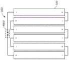
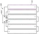
一方面,太阳能模块包括一串数量N大于或等于25个、彼此串联连接的矩形或实质上矩形的太阳能电池,这些太阳能电池平均具有大于约10伏的击穿电压。所述太阳能电池被集合成一个或多个超级电池,每个超级电池都包括成直线布置的两个或更多个太阳能电池,其中相邻太阳能电池的长边彼此重叠,并由既导电又导热的粘合剂传导性地彼此接合。在所述太阳能电池串中,没有单个太阳能电池或成组的总数小于N的太阳能电池与旁路二极管单独地并联电连接。沿着超级电池,穿过相邻太阳能电池相接合的重叠部分具备有效热传导,有利于太阳能模块安全可靠地工作,这种有效热传导避免或减少反偏太阳能电池中热点的形成。所述超级电池可被封装于例如夹在玻璃前板与玻璃后板之间的热塑性烯烃聚合物中,从而进一步增强模块对热损伤的耐受性。在一些变型形式中,N可大于或等于30、50或100。In one aspect, a solar module includes a string of rectangular or substantially rectangular solar cells, number N greater than or equal to 25, connected in series to each other, the solar cells having an average breakdown voltage greater than about 10 volts. The solar cells are assembled into one or more super cells, each super cell includes two or more solar cells arranged in a line, wherein the long sides of adjacent solar cells overlap each other, and are electrically and thermally conductive The adhesives conductively bond to each other. In said string of solar cells, no single solar cell or group of solar cells whose total number is less than N is individually electrically connected in parallel with the bypass diode. Along the super cell, there is effective heat conduction through the overlapping portion of adjacent solar cells, which is conducive to the safe and reliable operation of the solar module. This effective heat conduction avoids or reduces the formation of hot spots in reverse biased solar cells. The super cells may be encapsulated, for example, in a thermoplastic olefin polymer sandwiched between a glass front and glass back sheet, further enhancing the module's resistance to thermal damage. In some variations, N may be greater than or equal to 30, 50, or 100.
另一方面,超级电池包括多个硅太阳能电池,其中每个硅太阳能电池都具有矩形或实质上矩形的前(向阳侧)表面和背表面,这些表面的形状由相背对设置且平行的第一长边和第二长边、以及两条相背对设置的短边界定。每个太阳能电池包括:导电的前表面金属化图案,其包括邻近第一长边设置的至少一个前表面接触垫;以及导电的背表面金属化图案,其包括邻近第二长边设置的至少一个背表面接触垫。所述硅太阳能电池成直线布置,相邻硅太阳能电池的第一长边和第二长边重叠,并且相邻硅太阳能电池上的前表面接触垫和背表面接触垫重叠并由传导性粘合剂接合材料传导性地接合到彼此,从而将硅太阳能电池串联电连接。每个硅太阳能电池的前表面金属化图案包括屏障,该屏障被构造用于在制造超级电池期间,在传导性粘合剂接合材料固化之前实质上将传导性粘合剂接合材料局限于至少一个前表面接触垫。In another aspect, a super cell includes a plurality of silicon solar cells each having rectangular or substantially rectangular front (sun-side) and back surfaces shaped by oppositely disposed parallel first It is defined by a long side, a second long side, and two short sides opposite to each other. Each solar cell includes: a conductive front surface metallization pattern comprising at least one front surface contact pad disposed adjacent to a first long side; and a conductive back surface metallization pattern comprising at least one contact pad disposed adjacent a second long side back surface contact pad. The silicon solar cells are arranged in a straight line, the first long side and the second long side of the adjacent silicon solar cells overlap, and the front surface contact pads and the back surface contact pads on the adjacent silicon solar cells overlap and are bonded by conductive The agent bonding materials are conductively bonded to each other, thereby electrically connecting the silicon solar cells in series. The front surface metallization pattern of each silicon solar cell includes barriers configured to substantially confine the conductive adhesive bonding material to at least one Front surface contact pad.
另一方面,超级电池包括多个硅太阳能电池,其中每个硅太阳能电池都具有矩形或实质上矩形的前(向阳侧)表面和背表面,这些表面的形状由相背对设置且平行的第一长边和第二长边、以及两条相背对设置的短边界定。每个太阳能电池包括:导电的前表面金属化图案,其包括邻近第一长边设置的至少一个前表面接触垫;以及导电的背表面金属化图案,其包括邻近第二长边设置的至少一个背表面接触垫。所述硅太阳能电池成直线布置,相邻硅太阳能电池的第一长边和第二长边重叠,并且相邻硅太阳能电池上的前表面接触垫和背表面接触垫重叠并由传导性粘合剂接合材料传导性地接合到彼此,从而将硅太阳能电池串联电连接。每个硅太阳能电池的背表面金属化图案包括屏障,该屏障被构造用于在制造超级电池期间,在传导性粘合剂接合材料固化之前实质上将传导性粘合剂接合材料局限于至少一个背表面接触垫。In another aspect, a super cell includes a plurality of silicon solar cells each having rectangular or substantially rectangular front (sun-side) and back surfaces shaped by oppositely disposed parallel first It is defined by a long side, a second long side, and two short sides opposite to each other. Each solar cell includes: a conductive front surface metallization pattern comprising at least one front surface contact pad disposed adjacent to a first long side; and a conductive back surface metallization pattern comprising at least one contact pad disposed adjacent a second long side back surface contact pad. The silicon solar cells are arranged in a straight line, the first long side and the second long side of the adjacent silicon solar cells overlap, and the front surface contact pads and the back surface contact pads on the adjacent silicon solar cells overlap and are bonded by conductive The agent bonding materials are conductively bonded to each other, thereby electrically connecting the silicon solar cells in series. The back surface metallization pattern of each silicon solar cell includes a barrier configured to substantially confine the conductive adhesive bonding material to at least one back surface contact pad.
另一方面,制作太阳能电池串的方法包括:沿着平行于每个晶片的长边缘的多条线切割一个或多个准正方形硅晶片,而形成多个矩形硅太阳能电池,其中每个硅太阳能电池沿着其长轴的长度实质上相等。该方法还包括将矩形硅太阳能电池成直线布置,使相邻太阳能电池的长边重叠且传导性地接合到彼此,从而将太阳能电池串联电连接。所述多个矩形硅太阳能电池包括:具有两个倒角的至少一个矩形太阳能电池,所述倒角对应于准正方形晶片的拐角或拐角的一部分;以及各自缺少倒角的一个或多个矩形硅太阳能电池。通过使与包括倒角的矩形硅太阳能电池的长轴垂直的宽度大于与缺少倒角的矩形硅太阳能电池的长轴垂直的宽度,而对切割准正方形晶片所沿的平行线之间的间距进行选择,以便补偿倒角;因此,在太阳能电池串工作期间,太阳能电池串中的多个矩形硅太阳能电池中的每一个电池的前表面,暴露在太阳光下的面积实质上相等。In another aspect, a method of making a string of solar cells includes dicing one or more quasi-square silicon wafers along a plurality of lines parallel to a long edge of each wafer to form a plurality of rectangular silicon solar cells, wherein each silicon solar cell The cells are substantially equal in length along their long axis. The method also includes arranging the rectangular silicon solar cells in a line such that the long sides of adjacent solar cells overlap and are conductively bonded to each other, thereby electrically connecting the solar cells in series. The plurality of rectangular silicon solar cells includes: at least one rectangular solar cell having two chamfers corresponding to a corner or a portion of a corner of a quasi-square wafer; and one or more rectangular silicon solar cells each lacking a chamfer. Solar battery. The spacing between parallel lines along which quasi-square wafers are cut is adjusted by making the width perpendicular to the long axis of rectangular silicon solar cells that include chamfers larger than the width perpendicular to the long axis of rectangular silicon solar cells that lack chamfers. selected so as to compensate for the chamfer; thus, during operation of the solar cell string, the area of the front surface of each of the plurality of rectangular silicon solar cells in the solar cell string exposed to sunlight is substantially equal.
另一方面,超级电池包括成直线布置的多个硅太阳能电池,其中相邻太阳能电池的端部重叠且传导性地接合到彼此,从而将太阳能电池串联电连接。至少一个硅太阳能电池具有倒角,所述倒角对应于从其切割硅太阳能电池的准正方形硅晶片的拐角或拐角的一部分;至少一个硅太阳能电池缺少倒角;在太阳能电池串工作期间,每个硅太阳能电池的前表面暴露在太阳光下的面积实质上相等。A super cell, on the other hand, includes a plurality of silicon solar cells arranged in a line with ends of adjacent solar cells overlapping and conductively bonded to each other, thereby electrically connecting the solar cells in series. at least one silicon solar cell has a chamfer corresponding to a corner or part of a corner of a quasi-square silicon wafer from which the silicon solar cell is cut; at least one silicon solar cell lacks a chamfer; during operation of the solar cell string, each The areas of the front surfaces of the silicon solar cells exposed to sunlight are substantially equal.
另一方面,制作两个或更多个超级电池的方法包括:沿着平行于每个晶片的长边缘的多条线切割一个或多个准正方形硅晶片,而形成具有倒角的第一多个矩形硅太阳能电池,以及缺少倒角的第二多个矩形硅太阳能电池,其中所述倒角对应于准正方形硅晶片的拐角或拐角的一部分,所述第二多个矩形硅太阳能电池中的每个电池都具有第一长度,该第一长度的跨距等于准正方形硅晶片的全宽度。该方法还包括从第一多个矩形硅太阳能电池中的每一个电池移除倒角,而形成缺少倒角的第三多个矩形硅太阳能电池,所述第三多个矩形硅太阳能电池中的每个电池都具有比第一长度短的第二长度。该方法还包括:将第二多个矩形硅太阳能电池成直线布置,使相邻矩形硅太阳能电池的长边重叠且传导性地接合到彼此,而将第二多个矩形硅太阳能电池串联电连接,由此形成宽度等于第一长度的太阳能电池串;以及将第三多个矩形硅太阳能电池成直线布置,使相邻矩形硅太阳能电池的长边重叠且传导性地接合到彼此,而将第三多个矩形硅太阳能电池串联电连接,由此形成宽度等于第二长度的太阳能电池串。In another aspect, a method of making two or more super cells includes dicing one or more quasi-square silicon wafers along a plurality of lines parallel to the long rectangular silicon solar cells, and a second plurality of rectangular silicon solar cells lacking a chamfer, wherein the chamfer corresponds to a corner or a portion of a corner of a quasi-square silicon wafer, the second plurality of rectangular silicon solar cells Each cell has a first length spanning equal to the full width of the quasi-square silicon wafer. The method also includes removing a chamfer from each cell of the first plurality of rectangular silicon solar cells to form a third plurality of rectangular silicon solar cells lacking the chamfer, the rectangular silicon solar cells of the third plurality Each battery has a second length shorter than the first length. The method also includes arranging a second plurality of rectangular silicon solar cells in a line such that long sides of adjacent rectangular silicon solar cells overlap and are conductively bonded to each other, while electrically connecting the second plurality of rectangular silicon solar cells in series , thereby forming a string of solar cells having a width equal to the first length; and arranging a third plurality of rectangular silicon solar cells in a line such that the long sides of adjacent rectangular silicon solar cells overlap and are conductively bonded to each other, while the first plurality Three or more rectangular silicon solar cells are electrically connected in series, thereby forming a string of solar cells having a width equal to the second length.
另一方面,制作两个或更多个超级电池的方法包括:沿着平行于每个晶片的长边缘的多条线切割一个或多个准正方形硅晶片,而形成具有倒角的第一多个矩形硅太阳能电池,以及缺少倒角的第二多个矩形硅太阳能电池,其中所述倒角对应于准正方形硅晶片的拐角或拐角的一部分;将第一多个矩形硅太阳能电池成直线布置,使相邻矩形硅太阳能电池的长边重叠且传导性地接合到彼此,而将第一多个矩形硅太阳能电池串联电连接;以及将第二多个矩形硅太阳能电池成直线布置,使相邻矩形硅太阳能电池的长边重叠且传导性地接合到彼此,而将第二多个矩形硅太阳能电池串联电连接。In another aspect, a method of making two or more super cells includes dicing one or more quasi-square silicon wafers along a plurality of lines parallel to the long a rectangular silicon solar cell, and a second plurality of rectangular silicon solar cells lacking a chamfer, wherein the chamfer corresponds to a corner or a portion of a corner of a quasi-square silicon wafer; arranging the first plurality of rectangular silicon solar cells in a line , electrically connecting the first plurality of rectangular silicon solar cells in series by overlapping and conductively bonding the long sides of adjacent rectangular silicon solar cells to each other; and arranging the second plurality of rectangular silicon solar cells in line such that The long sides of adjacent rectangular silicon solar cells overlap and are conductively bonded to each other, electrically connecting a second plurality of rectangular silicon solar cells in series.
另一方面,超级电池包括:在第一方向上成直线布置的多个硅太阳能电池,其中相邻硅太阳能电池的端部重叠且传导性地接合到彼此,从而将硅太阳能电池串联电连接;以及细长的柔性电互连件,其长轴平行于与所述第一方向垂直的第二方向取向,所述细长的柔性电互连件具有下列特征:在沿着第二方向布置的多个分立位置处,传导性地接合到末端一个硅太阳能电池的前表面或背表面;在第二方向上至少延伸末端太阳能电池的全宽度;垂直于末端硅太阳能电池的前表面或后表面测量,导体厚度小于或等于约100微米;向沿第二方向流动的电流提供小于或等于约0.012欧姆的电阻;被构造用于提供柔性,该柔性在约–40℃至约85℃的温度范围内,调和末端硅太阳能电池与该电互连件之间在第二方向上的不均匀膨胀。In another aspect, the super cell includes: a plurality of silicon solar cells arranged in line in a first direction, wherein ends of adjacent silicon solar cells overlap and are conductively bonded to each other, thereby electrically connecting the silicon solar cells in series; and an elongate flexible electrical interconnect having a long axis oriented parallel to a second direction perpendicular to said first direction, said elongate flexible electrical interconnect having the following characteristics: Conductively bonded to the front or back surface of a terminal silicon solar cell at a plurality of discrete locations; extending at least the full width of the terminal solar cell in a second direction; measured perpendicular to the front or rear surface of the terminal silicon solar cell , having a conductor thickness of less than or equal to about 100 microns; providing a resistance to current flow in a second direction of less than or equal to about 0.012 ohms; configured to provide flexibility over a temperature range of about -40°C to about 85°C , to accommodate non-uniform expansion in the second direction between terminal silicon solar cells and the electrical interconnect.
例如,垂直于末端硅太阳能电池的前表面和后表面测量,所述柔性电互连件的导体厚度可小于或等于约30微米。所述柔性电互连件可以在第二方向上延伸到超级电池之外,以便在太阳能模块中至少为邻近该超级电池平行设置的第二超级电池提供电互连。此外或作为替代,所述柔性电互连件可以在第一方向上延伸到超级电池之外,以便在太阳能模块中为与该超级电池成直线平行设置的第二超级电池提供电互连。For example, the flexible electrical interconnect can have a conductor thickness of less than or equal to about 30 microns, measured perpendicular to the front and rear surfaces of the terminal silicon solar cells. The flexible electrical interconnection may extend beyond the super cell in a second direction to provide electrical interconnection for at least a second super cell disposed in parallel adjacent to the super cell in the solar module. Additionally or alternatively, the flexible electrical interconnection may extend beyond the super cell in the first direction to provide electrical interconnection for a second super cell arranged in-line parallel to the super cell in the solar module.
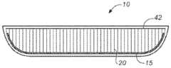
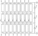
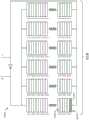
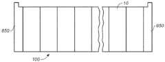
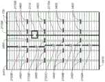
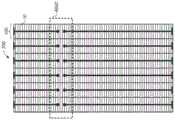
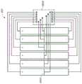
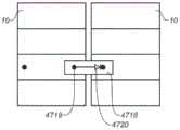
另一方面,太阳能模块包括多个超级电池,这些超级电池被布置成跨距等于模块宽度的两个或更多个平行的排,从而形成模块的前表面。每个超级电池都包括成直线布置的多个硅太阳能电池,其中相邻硅太阳能电池的端部重叠且传导性地接合到彼此,从而将硅太阳能电池串联电连接。第一排中与模块的边缘相邻的第一超级电池的至少一端经由柔性电互连件而电连接到第二排中与模块的同一边缘相邻的第二超级电池的一端,所述柔性电互连件具有下列特征:在多个分立位置处由导电粘合剂接合材料接合到第一超级电池的前表面;平行于模块的边缘延伸;其至少一部分折叠在第一超级电池的所述一端周围,因而从模块前方不可见。In another aspect, a solar module includes a plurality of super cells arranged in two or more parallel rows spanning a width equal to the module, forming the front surface of the module. Each super cell includes a plurality of silicon solar cells arranged in a line, with ends of adjacent silicon solar cells overlapping and conductively bonded to each other, thereby electrically connecting the silicon solar cells in series. At least one end of a first super cell in the first row adjacent to an edge of the module is electrically connected to an end of a second super cell in the second row adjacent to the same edge of the module via a flexible electrical interconnect, the flexible The electrical interconnect has the following features: bonded to the front surface of the first super cell by a conductive adhesive bonding material at a plurality of discrete locations; extending parallel to an edge of the module; at least a portion thereof folded over the first super cell around one end so it is not visible from the front of the module.
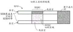
另一方面,制作超级电池的方法包括:在一个或多个硅太阳能电池中的每个电池上用激光划出一条或多条刻绘线,从而在硅太阳能电池上界定多个矩形区域;在邻近每个矩形区域的长边的一个或多个位置,将导电粘合剂接合材料施涂到一个或多个刻绘的硅太阳能电池上;沿刻绘线分割硅太阳能电池,得到多个矩形的硅太阳能电池,每个矩形的硅太阳能电池上都有一部分导电粘合剂接合材料设置在其前表面上与长边相邻的位置;将多个矩形的硅太阳能电池成直线布置,使相邻的矩形硅太阳能电池的长边以叠盖方式重叠,其间设置一部分导电粘合剂接合材料;然后使导电接合材料固化,从而将相邻的重叠矩形硅太阳能电池接合到彼此,并将这些电池串联电连接。In another aspect, a method of fabricating a super cell includes laser scribing one or more scribe lines on each of one or more silicon solar cells, thereby defining a plurality of rectangular regions on the silicon solar cells; applying a conductive adhesive bonding material to the one or more scribed silicon solar cells at one or more locations adjacent to the long sides of each rectangular area; dividing the silicon solar cells along the scribed lines to obtain a plurality of rectangular each rectangular silicon solar cell has a portion of the conductive adhesive bonding material disposed on its front surface adjacent to the long side; a plurality of rectangular silicon solar cells are arranged in a line so that The long sides of adjacent rectangular silicon solar cells are overlapped in a lapping manner, with a portion of the conductive adhesive bonding material interposed therebetween; the conductive bonding material is then cured, thereby bonding the adjacent overlapping rectangular silicon solar cells to each other, and bonding the cells electrically connected in series.
另一方面,制作超级电池的方法包括:在一个或多个硅太阳能电池中的每个电池上用激光划出一条或多条刻绘线,从而在硅太阳能电池上界定多个矩形区域;将导电粘合剂接合材料施涂到一个或多个硅太阳能电池的顶部表面的多个部分上;在一个或多个硅太阳能电池的底部表面与弯曲的支撑表面之间施加真空,以使一个或多个硅太阳能电池抵靠弯曲的支撑表面弯曲,而引起一个或多个硅太阳能电池沿着刻绘线切割,于是得到多个矩形的硅太阳能电池,每个矩形的硅太阳能电池上都有一部分导电粘合剂接合材料设置在其前表面上与长边相邻的位置;将多个矩形的硅太阳能电池成直线布置,使相邻的矩形硅太阳能电池的长边以叠盖方式重叠,其间设置一部分导电粘合剂接合材料;然后使导电接合材料固化,从而将相邻的重叠矩形硅太阳能电池接合到彼此,并将这些电池串联电连接。In another aspect, a method of fabricating a super cell includes laser scribing one or more scribe lines on each of one or more silicon solar cells, thereby defining a plurality of rectangular regions on the silicon solar cells; A conductive adhesive bonding material is applied to portions of the top surface of the one or more silicon solar cells; a vacuum is applied between the bottom surface of the one or more silicon solar cells and the curved support surface so that one or more The plurality of silicon solar cells are bent against the curved support surface causing one or more of the silicon solar cells to be cut along the scribe line, resulting in a plurality of rectangular silicon solar cells each having a portion of The conductive adhesive bonding material is provided on its front surface adjacent to the long sides; a plurality of rectangular silicon solar cells are arranged in a line so that the long sides of the adjacent rectangular silicon solar cells are overlapped in an overlapping manner, and therebetween A portion of the conductive adhesive bonding material is provided; the conductive bonding material is then cured, thereby bonding adjacent overlapping rectangular silicon solar cells to each other and electrically connecting the cells in series.
另一方面,制作太阳能模块的方法包括组装多个超级电池,每个超级电池都包括成直线布置的多个矩形硅太阳能电池,且端部在相邻的矩形硅太阳能电池的长边上以叠盖方式重叠。该方法还包括向超级电池施加热和压力,而使设置在相邻的矩形硅太阳能电池的重叠端部之间的导电接合材料固化,从而将相邻的重叠矩形硅太阳能电池接合到彼此,并将这些电池串联电连接。该方法还包括按所需的太阳能模块构造,将超级电池布置并互连为具有封装剂的层叠堆,然后向该层叠堆施加热和压力,从而形成层合结构。In another aspect, a method of fabricating a solar module includes assembling a plurality of super cells, each super cell comprising a plurality of rectangular silicon solar cells arranged in a line with ends stacked on the long side of adjacent rectangular silicon solar cells. The cover way overlaps. The method also includes applying heat and pressure to the super cell to cure the conductive bonding material disposed between the overlapping ends of the adjacent rectangular silicon solar cells, thereby bonding the adjacent overlapping rectangular silicon solar cells to each other, and These cells are electrically connected in series. The method also includes arranging and interconnecting the super cells into a laminated stack with encapsulant in the desired solar module configuration, and then applying heat and pressure to the laminated stack to form a laminated structure.
该方法的一些变型形式包括在向层叠堆施加热和压力以形成层合结构之前,通过将热和压力施加于超级电池来固化或部分固化所述导电接合材料,从而形成固化或部分固化的超级电池,作为形成层合结构之前的中间产品。在一些变型形式中,当在组装超级电池期间将每个附加的矩形硅太阳能电池添加到超级电池时,先使新添加的太阳能电池与相邻的重叠太阳能电池之间的导电粘合剂接合材料固化或部分固化,再将任何其他矩形硅太阳能电池添加到超级电池。作为替代,一些变型形式包括在同一步骤中将超级电池中所有的导电接合材料固化或部分固化。Some variations of the method include curing or partially curing the conductive bonding material by applying heat and pressure to the super cells prior to applying heat and pressure to the laminated stack to form a cured or partially cured super cell. Batteries, as an intermediate product before forming a laminated structure. In some variations, as each additional rectangular silicon solar cell is added to the super cell during assembly of the super cell, the conductive adhesive bonding material between the newly added solar cell and adjacent overlapping solar cells is first Cured or partially cured before adding any other rectangular silicon solar cells to the supercell. Alternatively, some variations include curing or partially curing all of the conductive bonding material in the super cell in the same step.
如果超级电池被形成为部分固化的中间产品,则该方法可包括在向层叠堆施加热和压力以形成层合结构的同时,完成导电接合材料的固化。If the super cell is formed as a partially cured intermediate product, the method may include completing curing of the conductive bonding material while applying heat and pressure to the laminated stack to form the laminated structure.
该方法的一些变型形式包括在向层叠堆施加热和压力以形成层合结构的同时,将导电接合材料固化,而无需形成固化或部分固化的超级电池作为形成层合结构之前的中间产品。Some variations of the method include curing the conductive bonding material while applying heat and pressure to the laminated stack to form the laminated structure without forming a cured or partially cured super cell as an intermediate product prior to forming the laminated structure.
该方法可包括将一个或多个标准尺寸的硅太阳能电池切割成面积较小的矩形形状,而提供矩形的硅太阳能电池。可在切割一个或多个硅太阳能电池之前将导电粘合剂接合材料施涂到所述一个或多个硅太阳能电池,以便提供预先施涂有导电粘合剂接合材料的矩形硅太阳能电池。作为替代,可以先切割一个或多个硅太阳能电池以提供矩形硅太阳能电池,然后才将导电粘合剂接合材料施涂到矩形硅太阳能电池。The method may include cutting one or more standard size silicon solar cells into a rectangular shape with a smaller area to provide rectangular silicon solar cells. The conductive adhesive bonding material may be applied to the one or more silicon solar cells prior to cutting the one or more silicon solar cells so as to provide rectangular silicon solar cells pre-applied with the conductive adhesive bonding material. Alternatively, one or more silicon solar cells may be cut to provide rectangular silicon solar cells before the conductive adhesive bonding material is applied to the rectangular silicon solar cells.
一方面,太阳能模块包括被布置成两个或更多个平行排的多个超级电池。每个超级电池都包括多个成直线布置的矩形或实质上矩形的硅太阳能电池,其中相邻硅太阳能电池的长边重叠且传导性地直接接合到彼此,从而将硅太阳能电池串联电连接。太阳能板还包括:位于第一太阳能电池的背表面上的第一隐藏的分接头接触垫,所述第一太阳能电池位于沿着第一个超级电池的中间位置;以及传导性地接合到第一隐藏的分接头接触垫的第一电互连件。所述第一电互连件包括应力消除特征,该应力消除特征调和该电互连件与该电互连件所接合的硅太阳能电池之间的不均匀热膨胀。本文结合互连件使用的术语“应力消除特征”,可以指几何特征,诸如扭结、环或狭槽,也可以指互连件的厚度(例如,极薄)和/或互连件的延展性。例如,应力消除特征可以指,互连件是由极薄的铜带形成的。In one aspect, a solar module includes a plurality of super cells arranged in two or more parallel rows. Each super cell includes a plurality of rectangular or substantially rectangular silicon solar cells arranged in a line, with the long sides of adjacent silicon solar cells overlapping and conductively bonded directly to each other, thereby electrically connecting the silicon solar cells in series. The solar panel also includes: a first hidden tap contact pad on the back surface of the first solar cell located midway along the first super cell; and conductively bonded to the first super cell. A first electrical interconnect of the hidden tap contact pad. The first electrical interconnect includes a stress relief feature that accommodates non-uniform thermal expansion between the electrical interconnect and a silicon solar cell to which the electrical interconnect is bonded. The term "stress relief feature" as used herein in connection with an interconnect may refer to a geometric feature, such as a kink, loop, or slot, and may refer to the thickness (e.g., extremely thin) of the interconnect and/or the ductility of the interconnect . For example, a stress relief feature may mean that the interconnects are formed from extremely thin strips of copper.
太阳能模块可包括位于第二太阳能电池的背表面上的第二隐藏的分接头接触垫,所述第二太阳能电池位于第一太阳能电池附近,且位于沿着相邻超级电池排中的第二个超级电池的中间位置,其中第一隐藏的分接头接触垫通过第一电互连件而电连接到第二隐藏的分接头接触垫。在此类情况下,第一电互连件可延伸穿过第一超级电池与第二超级电池之间的间隙,并传导性地接合到第二隐藏的分接头接触垫。作为替代,第一隐藏的分接头接触垫与第二隐藏的分接头接触垫之间的电连接可包括另一个电互连件,所述另一个电互连件传导性地接合到第二隐藏的分接头接触垫并电连接(例如,传导性地接合)到第一电互连件。任一种互连方案都可任选地延伸穿过额外的超级电池排。例如,任一种互连方案都可任选地延伸穿过模块的全宽度,从而经由隐藏的分接头接触垫来互连每排中的太阳能电池。The solar module may include a second hidden tap contact pad on the back surface of a second solar cell located adjacent to the first solar cell and located along the second of the adjacent rows of super cells. An intermediate position of the super cell, wherein the first hidden tap contact pad is electrically connected to the second hidden tap contact pad through the first electrical interconnect. In such cases, the first electrical interconnect may extend across the gap between the first super cell and the second super cell and be conductively bonded to the second hidden tap contact pad. Alternatively, the electrical connection between the first recessed tap contact pad and the second recessed tap contact pad may include another electrical interconnect conductively bonded to the second recessed tap contact pad. The tap contacts the pads and is electrically connected (eg, conductively bonded) to the first electrical interconnect. Either interconnection scheme can optionally be extended through additional rows of super cells. For example, either interconnection scheme can optionally extend across the full width of the module, interconnecting the solar cells in each row via hidden tap contact pads.
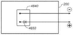
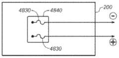
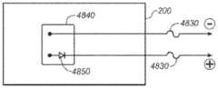
太阳能模块可包括:位于第二太阳能电池的背表面上的第二隐藏的分接头接触垫,所述第二太阳能电池位于沿着第一个超级电池的另一个中间位置;传导性地接合到第二隐藏的分接头接触垫的第二电互连件;以及旁路二极管,该旁路二极管利用第一电互连件和第二电互连件与位于第一隐藏的分接头接触垫和第二隐藏的分接头接触垫之间的太阳能电池并联电连接。The solar module may include: a second hidden tap contact pad on the back surface of a second solar cell located at another intermediate location along the first super cell; conductively bonded to the first super cell; A second electrical interconnection of two hidden tap contact pads; and a bypass diode utilizing the first electrical interconnection and the second electrical interconnection with the first hidden tap contact pad and the second electrical interconnection The solar cells are electrically connected in parallel between the two hidden tap contact pads.
在上述任一种变型形式中,第一隐藏的分接头接触垫可以是被布置在与第一太阳能电池的长轴平行延伸的一排中的第一太阳能电池的背表面上的多个隐藏的分接头接触垫中的一个,其中第一电互连件传导性地接合到多个隐藏的触点中的每一个,并且其沿着所述长轴的跨距实质上等于第一太阳能电池的长度。此外或作为替代,第一隐藏的接触垫可以是被布置在与第一太阳能电池的长轴垂直延伸的一排中的第一太阳能电池的背表面上的多个隐藏的分接头接触垫中的一个。在后一种情况下,例如,这排隐藏的分接头接触垫的位置可与第一太阳能电池的短边缘相邻。第一隐藏的接触垫可以是在第一太阳能电池的背表面上被布置成二维阵列的多个隐藏的分接头接触垫中的一个。In any of the above variations, the first hidden tap contact pads may be a plurality of hidden tap contact pads arranged on the back surface of the first solar cell in a row extending parallel to the long axis of the first solar cell. one of the tap contact pads, wherein the first electrical interconnect is conductively bonded to each of the plurality of hidden contacts and has a span along the long axis substantially equal to that of the first solar cell length. Additionally or alternatively, the first hidden contact pad may be one of a plurality of hidden tap contact pads arranged on the back surface of the first solar cell in a row extending perpendicularly to the long axis of the first solar cell. one. In the latter case, for example, the row of hidden tap contact pads may be located adjacent to the short edge of the first solar cell. The first hidden contact pad may be one of a plurality of hidden tap contact pads arranged in a two-dimensional array on the back surface of the first solar cell.
作为替代,在上述任一种变型形式中,第一隐藏的分接头接触垫的位置可与第一太阳能电池的背表面的短边相邻,其中第一电互连件并不沿着所述太阳能电池的长轴从所述隐藏的分接头接触垫实质上向内延伸,并且第一太阳能电池上的背表面金属化图案为所述互连件提供传导路径,该传导路径优选地具有小于或等于约每平方5欧姆的薄膜电阻、或者小于或等于约每平方2.5欧姆的薄膜电阻。在此类情况下,第一互连件可包括(例如)设置在应力消除特征的相对侧上的两个突出部,其中一个突出部传导性地接合到第一隐藏的分接头接触垫。这两个突出部可具有不同的长度。Alternatively, in any of the above variations, the location of the first hidden tap contact pad may be adjacent to a short side of the back surface of the first solar cell, wherein the first electrical interconnect is not along the The long axis of the solar cell extends substantially inwardly from the hidden tap contact pad, and the back surface metallization pattern on the first solar cell provides a conductive path for the interconnect, preferably with a diameter less than or A sheet resistance equal to about 5 ohms per square, or a sheet resistance less than or equal to about 2.5 ohms per square. In such cases, the first interconnect may include, for example, two protrusions disposed on opposite sides of the strain relief feature, one of the protrusions conductively bonded to the first hidden tap contact pad. The two protrusions may have different lengths.
在上述任一种变型形式中,第一电互连件可包括对准特征,所述对准特征用于识别是否与第一隐藏的分接头接触垫理想地对准、是否与第一超级电池的边缘理想地对准,或用于识别是否既与第一隐藏的分接头接触垫理想地对准、又与第一超级电池的边缘理想地对准。In any of the above variations, the first electrical interconnect may include alignment features for identifying whether it is ideally aligned with the first hidden tap contact pad, with the first super cell The edge of , or used to identify whether it is ideally aligned with both the first hidden tap contact pad and the edge of the first super cell.
另一方面,太阳能模块包括玻璃前板、后板以及多个超级电池,所述多个超级电池在玻璃前板与后板之间布置成两个或更多个平行排。每个超级电池都包括多个成直线布置的矩形或实质上矩形的硅太阳能电池,其中相邻硅太阳能电池的长边重叠且既柔性又传导性地直接接合到彼此,从而将硅太阳能电池串联电连接。第一柔性电互连件刚性地、传导性地接合到第一个超级电池。重叠的太阳能电池之间的柔性传导性接合为超级电池提供机械可塑性,从而在约-40℃至约100℃的温度范围内,调和平行于超级电池排的方向上超级电池与玻璃前板之间的热膨胀失配,使该热膨胀失配不至于损坏太阳能模块。第一超级电池与第一柔性电互连件之间的刚性传导性接合迫使第一柔性电互连件在约-40℃至约180℃的温度范围内,调和垂直于超级电池排的方向上第一超级电池与第一柔性电互连件之间的热膨胀失配,使该热膨胀失配不至于损坏太阳能模块。In another aspect, a solar module includes a glass front sheet, a back sheet, and a plurality of super cells arranged in two or more parallel rows between the glass front sheet and the back sheet. Each super cell consists of a plurality of rectangular or substantially rectangular silicon solar cells arranged in a line, with the long sides of adjacent silicon solar cells overlapping and directly bonded to each other both flexibly and conductively, thereby connecting the silicon solar cells in series electrical connection. A first flexible electrical interconnect is rigidly and conductively bonded to the first super cell. The flexible conductive bond between the overlapping solar cells provides the super cell with mechanical plasticity, reconciling the super cell and the glass front sheet in the direction parallel to the super cell row in the temperature range of about -40°C to about 100°C The thermal expansion mismatch, so that the thermal expansion mismatch will not damage the solar module. The rigid conductive bond between the first super cell and the first flexible electrical interconnect forces the first flexible electrical interconnect to reconcile in a direction perpendicular to the row of super cells in a temperature range of about -40°C to about 180°C The thermal expansion mismatch between the first super cell and the first flexible electrical interconnect is such that the thermal expansion mismatch does not damage the solar module.
超级电池内重叠的相邻太阳能电池之间的传导性接合与超级电池和柔性电互连件之间的传导性接合可利用不同的传导性粘合剂。超级电池内至少一个太阳能电池一侧的传导性接合与该太阳能电池另一侧的传导性接合可利用不同的传导性粘合剂。例如,形成超级电池与柔性电互连件之间的刚性接合的传导性粘合剂可以是焊料。在一些变型形式中,超级电池内的重叠太阳能电池之间的传导性接合是用非焊料传导性粘合剂形成的,而超级电池与柔性电互连件之间的传导性接合是用焊料形成的。Conductive bonding between overlapping adjacent solar cells within a super cell and conductive bonding between super cells and flexible electrical interconnects may utilize different conductive adhesives. The conductive bond on one side of at least one solar cell in a super cell may utilize a different conductive adhesive than the conductive bond on the other side of the solar cell. For example, the conductive adhesive that forms the rigid bond between the super cell and the flexible electrical interconnect can be solder. In some variations, the conductive bond between overlapping solar cells within the super cell is formed with a non-solder conductive adhesive, while the conductive bond between the super cell and the flexible electrical interconnect is formed with solder of.
在利用刚描述的两种不同的传导性粘合剂的一些变型形式中,这两种传导性粘合剂可在同一加工步骤中固化(例如,在同一温度下、同一压力下和/或同一时间间隔内固化)。In some variations of the two different conductive adhesives just described, the two conductive adhesives may be cured in the same processing step (e.g., at the same temperature, at the same pressure, and/or at the same solidified over time).
重叠的相邻太阳能电池之间的传导性接合可调和例如每个电池与玻璃前板之间大于或等于约15微米的差动运动。Conductive bonding between overlapping adjacent solar cells can accommodate, for example, differential motion of greater than or equal to about 15 microns between each cell and the glass front sheet.
例如,重叠的相邻太阳能电池之间的传导性接合在垂直于太阳能电池方向上的厚度可小于或等于约50微米,而在垂直于太阳能电池方向上的热导率可大于或等于约1.5W/(m-K)。For example, a conductive bond between overlapping adjacent solar cells can have a thickness perpendicular to the solar cells of less than or equal to about 50 microns and a thermal conductivity perpendicular to the solar cells of greater than or equal to about 1.5 W /(m-K).
例如,第一柔性电互连件本身可承受大于或等于约40微米的热膨胀或热收缩。For example, the first flexible electrical interconnect itself can withstand thermal expansion or contraction of greater than or equal to about 40 microns.
第一柔性电互连件中传导性地接合到超级电池的那部分可以呈带状、由铜形成,而且在垂直于其与太阳能电池接合的表面的方向上的厚度可例如小于或等于约30微米,或者小于或等于约50微米。第一柔性电互连件可包括一体式传导性铜部分,该部分不与太阳能电池接合,并且相比第一柔性电互连件中传导性地接合到太阳能电池的那部分提供更高的传导性。第一柔性电互连件在垂直于其与太阳能电池接合的表面的方向上的厚度可小于或等于约30微米、或者小于或等于约50微米,而且在太阳能电池表面所处的平面中,在与流过该电互连件的电流垂直的方向上的宽度大于或等于约10mm。第一柔性电互连件可传导性地接合到太阳能电池附近相比第一电互连件提供更高传导性的导体。The portion of the first flexible electrical interconnect that is conductively bonded to the super cell may be ribbon-shaped, formed of copper, and may have a thickness in a direction perpendicular to its surface to which the solar cell is bonded, for example, less than or equal to about 30 microns, or less than or equal to about 50 microns. The first flexible electrical interconnect may include an integral conductive copper portion that does not bond to the solar cell and provides higher conduction than that portion of the first flexible electrical interconnect that is conductively bonded to the solar cell sex. The thickness of the first flexible electrical interconnect in a direction perpendicular to its surface to which the solar cell is bonded may be less than or equal to about 30 microns, or less than or equal to about 50 microns, and in the plane of the solar cell surface The width in a direction perpendicular to the flow of electrical current through the electrical interconnect is greater than or equal to about 10 mm. The first flexible electrical interconnect can be conductively bonded to a conductor that provides higher conductivity than the first electrical interconnect in the vicinity of the solar cell.
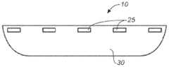
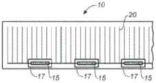
另一方面,太阳能模块包括被布置成两个或更多个平行排的多个超级电池。每个超级电池都包括多个成直线布置的矩形或实质上矩形的硅太阳能电池,其中相邻硅太阳能电池的长边重叠且传导性地直接接合到彼此,从而将硅太阳能电池串联电连接。在正常工作时不传导大电流的隐藏的分接头接触垫位于第一太阳能电池的背表面上,所述第一太阳能电池位于沿着第一排超级电池中的第一个超级电池的中间位置。隐藏的分接头接触垫并联电连接到第二排超级电池中的至少第二个太阳能电池。In another aspect, a solar module includes a plurality of super cells arranged in two or more parallel rows. Each super cell includes a plurality of rectangular or substantially rectangular silicon solar cells arranged in a line, with the long sides of adjacent silicon solar cells overlapping and conductively bonded directly to each other, thereby electrically connecting the silicon solar cells in series. Hidden tap contact pads that do not conduct high currents during normal operation are located on the back surface of the first solar cell located midway along the first super cell in the first row of super cells. The hidden tap contact pads are electrically connected in parallel to at least a second solar cell in the second row of super cells.
太阳能模块可包括下述电互连件:该电互连件接合到隐藏的分接头接触垫,并将隐藏的分接头接触垫电互连到第二太阳能电池。在一些变型形式中,所述电互连件的跨距实质上不等于第一太阳能电池的长度,并且第一太阳能电池上的背表面金属化图案为隐藏的分接头接触垫提供传导路径,该传导路径具有小于或等于约每平方5欧姆的薄膜电阻。The solar module may include electrical interconnects that bond to the hidden tap contact pads and electrically interconnect the hidden tap contact pads to the second solar cell. In some variations, the span of the electrical interconnect is not substantially equal to the length of the first solar cell, and the back surface metallization pattern on the first solar cell provides a conductive path for a hidden tap contact pad, the The conductive path has a sheet resistance of less than or equal to about 5 ohms per square.
多个超级电池可被布置成三个或更多个平行排,这些平行排的跨距等于太阳能模块在垂直于这些排的方向上的宽度,并且隐藏的分接头接触垫电连接到每一个超级电池排中的至少一个太阳能电池上的隐藏的接触垫,从而将所有的超级电池排并联电连接。在此类变型形式中,太阳能模块可包括连接到至少一个隐藏的分接头接触垫或者连接到隐藏的分接头接触垫之间的互连件的至少一个总线连接,该总线连接与旁路二极管或其他电子装置连接。Multiple super cells may be arranged in three or more parallel rows spanning equal to the width of the solar module in a direction perpendicular to the rows, with hidden tap contact pads electrically connected to each super cell. Hidden contact pads on at least one solar cell in a row, thereby electrically connecting all super rows in parallel. In such variations, the solar module may include at least one bus connection connected to at least one hidden tap contact pad or to an interconnect between hidden tap contact pads, the bus connection being connected to a bypass diode or Other electronic devices are connected.
太阳能模块可包括下述柔性电互连件:该柔性电互连件传导性地接合到隐藏的分接头接触垫,从而将该隐藏的分接头接触垫电连接到第二太阳能电池。柔性电互连件中传导性地接合到隐藏的分接头接触垫的那部分可以例如呈带状、由铜形成,而且在垂直于其与太阳能电池接合的表面的方向上的厚度可小于或等于约50微米。隐藏的分接头接触垫与柔性电互连件之间的传导性接合可迫使柔性电互连件承受第一太阳能电池与柔性电互连件之间的热膨胀失配,并且在约-40℃至约180℃的温度范围内,调和第一太阳能电池与第二太阳能电池之间由热膨胀造成的相对运动,使该相对运动不至于损坏太阳能模块。The solar module may include a flexible electrical interconnect conductively bonded to the hidden tap contact pad to electrically connect the hidden tap contact pad to the second solar cell. The portion of the flexible electrical interconnect that is conductively bonded to the hidden tap contact pad may, for example, be in the shape of a ribbon, formed of copper, and may have a thickness in a direction perpendicular to its surface to which the solar cell is bonded that is less than or equal to about 50 microns. The conductive bond between the hidden tap contact pad and the flexible electrical interconnect can force the flexible electrical interconnect to withstand a thermal expansion mismatch between the first solar cell and the flexible electrical interconnect, and at about -40°C to Within the temperature range of about 180° C., the relative movement caused by thermal expansion between the first solar cell and the second solar cell is adjusted so that the relative movement will not damage the solar module.
在一些变型形式中,太阳能模块在工作时,第一隐藏的接触垫可传导比任何单个太阳能电池中生成的电流更大的电流。In some variations, when the solar module is in operation, the first hidden contact pad can conduct a greater current than is generated in any single solar cell.
通常情况下,覆盖在第一隐藏的分接头接触垫上面的第一太阳能电池的前表面并未被接触垫或任何其他互连件特征占据。通常情况下,第一太阳能电池的前表面上未被第一超级电池中的相邻太阳能电池的一部分重叠的任何区域都未被接触垫或任何其他互连件特征占据。Typically, the front surface of the first solar cell overlying the first hidden tap contact pad is not occupied by a contact pad or any other interconnect feature. Typically, any area on the front surface of the first solar cell that is not overlapped by a portion of an adjacent solar cell in the first super cell is not occupied by a contact pad or any other interconnect feature.
在一些变型形式中,每个超级电池中的大部分电池都不具有隐藏的分接头接触垫。在此类变型形式中,具有隐藏的分接头接触垫的电池相比不具有隐藏的分接头接触垫的电池,可具有较大的光收集区域。In some variations, a majority of the cells in each supercell do not have hidden tap contact pads. In such variations, cells with hidden tap contact pads may have a larger light collection area than cells without hidden tap contact pads.
另一方面,太阳能模块包括玻璃前板、后板以及多个超级电池,所述多个超级电池在玻璃前板与后板之间布置成两个或更多个平行排。每个超级电池都包括多个成直线布置的矩形或实质上矩形的硅太阳能电池,其中相邻硅太阳能电池的长边重叠且既柔性又传导性地直接接合到彼此,从而将硅太阳能电池串联电连接。第一柔性电互连件刚性地、传导性地接合到第一个超级电池。重叠的太阳能电池之间的柔性传导性接合由第一传导性粘合剂形成,其具有小于或等于约800兆帕的剪切模量。第一超级电池与第一柔性电互连件之间的刚性传导性接合由第二传导性粘合剂形成,其具有大于或等于约2000兆帕的剪切模量。In another aspect, a solar module includes a glass front sheet, a back sheet, and a plurality of super cells arranged in two or more parallel rows between the glass front sheet and the back sheet. Each super cell consists of a plurality of rectangular or substantially rectangular silicon solar cells arranged in a line, with the long sides of adjacent silicon solar cells overlapping and directly bonded to each other both flexibly and conductively, thereby connecting the silicon solar cells in series electrical connection. A first flexible electrical interconnect is rigidly and conductively bonded to the first super cell. A flexible conductive bond between the overlapping solar cells is formed from a first conductive adhesive having a shear modulus of less than or equal to about 800 MPa. A rigid conductive bond between the first super cell and the first flexible electrical interconnect is formed by a second conductive adhesive having a shear modulus greater than or equal to about 2000 MPa.
第一传导性粘合剂可具有(例如)低于或等于约0℃的玻璃转化温度。The first conductive adhesive can have, for example, a glass transition temperature of less than or equal to about 0°C.
在一些变型形式中,第一传导性粘合剂和第二传导性粘合剂是不同的,但这两种传导性粘合剂可在同一加工步骤中固化。In some variations, the first conductive adhesive and the second conductive adhesive are different, but both conductive adhesives can be cured in the same processing step.
在一些变型形式中,重叠的相邻太阳能电池之间的传导性接合在垂直于太阳能电池方向上的厚度小于或等于约50微米,而在垂直于太阳能电池方向上的热导率大于或等于约1.5W/(m-K)。In some variations, the conductive bond between overlapping adjacent solar cells has a thickness perpendicular to the solar cells of less than or equal to about 50 microns and a thermal conductivity perpendicular to the solar cells of greater than or equal to about 1.5W/(m-K).
一方面,太阳能模块包括数量N大于或等于约150个矩形或实质上矩形的硅太阳能电池,这些硅太阳能电池被布置成位于两个或更多个平行排中的多个超级电池。每个超级电池都包括成直线布置的多个硅太阳能电池,其中相邻的硅太阳能电池的长边重叠且传导性地接合到彼此,从而将硅太阳能电池串联电连接。超级电池电连接,用于提供大于或等于约90伏的高直流电压。In one aspect, a solar module includes a number N greater than or equal to about 150 rectangular or substantially rectangular silicon solar cells arranged as a plurality of super cells in two or more parallel rows. Each super cell includes a plurality of silicon solar cells arranged in a line, with the long sides of adjacent silicon solar cells overlapping and conductively bonded to each other, thereby electrically connecting the silicon solar cells in series. The super battery is electrically connected to provide a high DC voltage greater than or equal to about 90 volts.
在一种变型形式中,太阳能模块包括一个或多个柔性电互连件,所述柔性电互连件被布置用于将多个超级电池串联电连接,从而提供高直流电压。太阳能模块可包括模块级功率电子器件,所述模块级功率电子器件包括用于将高直流电压转变成交流电压的逆变器。模块级功率电子器件可感测高直流电压,并且可在最佳电流-电压功率点处操作太阳能模块。In one variation, the solar module includes one or more flexible electrical interconnects arranged to electrically connect a plurality of super cells in series to provide a high DC voltage. Solar modules may include module-level power electronics including inverters for converting high DC voltages to AC voltages. Module-level power electronics sense high DC voltages and operate solar modules at the optimum current-voltage power point.
在另一种变型形式中,太阳能模块包括电连接到各对相邻的串联超级电池排的模块级功率电子器件,用于串联电连接一对或多对超级电池排以提供高直流电压,该模块级功率电子器件包括用于将高直流电压转变成交流电压的逆变器。任选地,模块级功率电子器件可感测每个单独的一对超级电池排两端的电压,并且可在最佳电流-电压功率点处操作每个单独的一对超级电池排。任选地,如果单独的一对超级电池排两端的电压低于阈值,则模块级功率电子器件可将这对超级电池排从提供高直流电压的电路断开。In another variant, the solar module includes module-level power electronics electrically connected to each pair of adjacent series-connected rows of super cells for electrically connecting one or more pairs of rows of super cells in series to provide a high DC voltage, the Module-level power electronics include inverters for converting high DC voltages to AC voltages. Optionally, module level power electronics can sense the voltage across each individual pair of super cell banks and can operate each individual pair of super cell banks at an optimal current-voltage power point. Optionally, the module level power electronics may disconnect an individual pair of super cell banks from the circuit providing the high DC voltage if the voltage across the pair is below a threshold.
在另一种变型形式中,太阳能模块包括电连接到每个单独的超级电池排的模块级功率电子器件,用于串联电连接两个或更多个超级电池排以提供高直流电压,该模块级功率电子器件包括用于将高直流电压转变成交流电压的逆变器。任选地,模块级功率电子器件可感测每个单独的超级电池排两端的电压,并且可在最佳电流-电压功率点处操作每个单独的超级电池排。任选地,如果单独的超级电池排两端的电压低于阈值,则模块级功率电子器件可将这个单独的超级电池排从提供高直流电压的电路断开。In another variant, the solar module includes module-level power electronics electrically connected to each individual super-bank for electrically connecting two or more super-banks in series to provide a high DC voltage, the module Level power electronics include inverters for converting high DC voltages into AC voltages. Optionally, module-level power electronics can sense the voltage across each individual super cell bank and can operate each individual super cell bank at an optimal current-voltage power point. Optionally, the module level power electronics may disconnect an individual super cell bank from the circuit providing the high DC voltage if the voltage across the individual super cell bank is below a threshold.
在另一种变型形式中,太阳能模块包括电连接到每个单独的超级电池的模块级功率电子器件,用于串联电连接两个或更多个超级电池以提供高直流电压,该模块级功率电子器件包括用于将高直流电压转变成交流电压的逆变器。任选地,模块级功率电子器件可感测每个单独的超级电池两端的电压,并且可在最佳电流-电压功率点处操作每个单独的超级电池。任选地,如果单独的超级电池两端的电压低于阈值,则模块级功率电子器件可将这个单独的超级电池从提供高直流电压的电路断开。In another variant, the solar module includes module-level power electronics electrically connected to each individual super cell for electrically connecting two or more super cells in series to provide a high DC voltage, the module-level power Electronics include inverters for converting high DC voltages to AC voltages. Optionally, module level power electronics can sense the voltage across each individual super cell and can operate each individual super cell at an optimal current-voltage power point. Optionally, the module level power electronics may disconnect an individual super cell from the circuit providing the high DC voltage if the voltage across the individual super cell is below a threshold.
在另一种变型形式中,模块内的每个超级电池都被隐藏的分接头电分段成多个分段。太阳能模块包括通过隐藏的分接头电连接到每个超级电池中的每个分段的模块级功率电子器件,用于串联电连接两个或更多个分段以提供高直流电压,该模块级功率电子器件包括用于将高直流电压转变成交流电压的逆变器。任选地,模块级功率电子器件可感测每个超级电池中的每个单独的分段两端的电压,并且可在最佳电流-电压功率点处操作每个单独的分段。任选地,如果单独的分段两端的电压低于阈值,则模块级功率电子器件可将这个单独的分段从提供高直流电压的电路断开。In another variant, each super cell within the module is electrically segmented into multiple segments by hidden taps. Solar modules include module-level power electronics electrically connected to each segment in each super cell through hidden taps for electrically connecting two or more segments in series to provide high DC voltage, the module-level Power electronics include inverters for converting high DC voltages into AC voltages. Optionally, module level power electronics can sense the voltage across each individual segment in each super cell and can operate each individual segment at an optimal current-voltage power point. Optionally, the module level power electronics may disconnect an individual segment from the circuit supplying the high DC voltage if the voltage across the individual segment is below a threshold.
在上述任一种变型形式中,最佳电流-电压功率点可以是最大电流-电压功率点。In any of the above variations, the optimum current-voltage power point may be the maximum current-voltage power point.
在上述任一种变型形式中,模块级功率电子器件可能缺少直流到直流升压部件。In any of the above variants, the module-level power electronics may lack a DC-to-DC boost component.
在上述任一种变型形式中,N可以大于或等于约200、大于或等于约250、大于或等于约300、大于或等于约350、大于或等于约400、大于或等于约450、大于或等于约500、大于或等于约550、大于或等于约600、大于或等于约650,或者大于或等于约700。In any of the above variations, N can be about 200 or more, about 250 or more, about 300 or more, about 350 or more, about 400 or more, about 450 or more, About 500, about 550 or greater, about 600 or greater, about 650 or greater, or about 700 or greater.
在上述任一种变型形式中,高直流电压可以大于或等于约120伏、大于或等于约180伏、大于或等于约240伏、大于或等于约300伏、大于或等于约360伏、大于或等于约420伏、大于或等于约480伏、大于或等于约540伏,或者大于或等于约600伏。In any of the above variations, the high DC voltage may be about 120 volts or greater, about 180 volts or greater, about 240 volts or greater, about 300 volts or greater, about 360 volts or greater, Equal to about 420 volts, greater than or equal to about 480 volts, greater than or equal to about 540 volts, or greater than or equal to about 600 volts.
另一方面,太阳能光伏系统包括并联电连接的两个或更多个太阳能模块,以及逆变器。每个太阳能模块都包括数量N大于或等于约150个矩形或实质上矩形的硅太阳能电池,这些硅太阳能电池被布置成位于两个或更多个平行排中的多个超级电池。每个模块中的每个超级电池都包括成直线布置在该模块中的两个或更多个硅太阳能电池,其中相邻的硅太阳能电池的长边重叠且传导性地接合到彼此,从而将硅太阳能电池串联电连接。每个模块中的超级电池电连接,用于使模块提供大于或等于约90伏的高电压直流输出。逆变器电连接到两个或更多个太阳能模块,从而将这些模块的高电压直流输出转变成交流电。On the other hand, a solar photovoltaic system includes two or more solar modules electrically connected in parallel, and an inverter. Each solar module includes a number N greater than or equal to about 150 rectangular or substantially rectangular silicon solar cells arranged as a plurality of super cells in two or more parallel rows. Each super cell in each module consists of two or more silicon solar cells arranged in a line in the module, with the long sides of adjacent silicon solar cells overlapping and conductively bonded to each other such that the The silicon solar cells are electrically connected in series. The super cells in each module are electrically connected for the module to provide a high voltage DC output of greater than or equal to about 90 volts. An inverter is electrically connected to two or more solar modules, converting the high voltage DC output of these modules into AC power.
每个太阳能模块都可包括一个或多个柔性电互连件,所述柔性电互连件被布置用于将太阳能模块中的超级电池串联电连接,从而提供太阳能模块的高电压直流输出。Each solar module may include one or more flexible electrical interconnects arranged to electrically connect the super cells in the solar module in series to provide a high voltage DC output from the solar module.
太阳能光伏系统可包括与并联电连接的两个或更多个太阳能模块中的第一个太阳能模块串联电连接的至少第三个太阳能模块。在此类情况下,第三个太阳能模块可包括数量N’大于或等于约150个矩形或实质上矩形的硅太阳能电池,这些硅太阳能电池被布置成位于两个或更多个平行排中的多个超级电池。第三个太阳能模块中的每个超级电池都包括成直线布置在该模块中的两个或更多个硅太阳能电池,其中相邻的硅太阳能电池的长边重叠且传导性地接合到彼此,从而将硅太阳能电池串联电连接。第三个太阳能模块中的超级电池电连接,用于使模块提供大于或等于约90伏的高电压直流输出。The solar photovoltaic system may include at least a third solar module electrically connected in series with a first solar module of the two or more solar modules electrically connected in parallel. In such cases, the third solar module may comprise a number N' greater than or equal to about 150 rectangular or substantially rectangular silicon solar cells arranged in two or more parallel rows Multiple super batteries. Each super cell in the third solar module comprises two or more silicon solar cells arranged in a line in the module with the long sides of adjacent silicon solar cells overlapping and conductively bonded to each other, The silicon solar cells are thus electrically connected in series. The super battery in the third solar module is electrically connected for the module to provide a high voltage DC output greater than or equal to about 90 volts.
包括刚描述的与两个或更多个太阳能模块中的第一个太阳能模块串联电连接的第三个太阳能模块的变型形式,还可包括与并联电连接的两个或更多个太阳能模块中的第二个太阳能模块串联电连接的至少第四个太阳能模块。第四个太阳能模块可包括数量N”大于或等于约150个矩形或实质上矩形的硅太阳能电池,这些硅太阳能电池被布置成位于两个或更多个平行排中的多个超级电池。第四个太阳能模块中的每个超级电池都包括成直线布置在该模块中的两个或更多个硅太阳能电池,其中相邻的硅太阳能电池的长边重叠且传导性地接合到彼此,从而将硅太阳能电池串联电连接。第四个太阳能模块中的超级电池电连接,用于使模块提供大于或等于约90伏的高电压直流输出。Variations that include a third solar module just described electrically connected in series with a first of two or more solar modules may also include two or more solar modules electrically connected in parallel The second solar module is electrically connected in series with at least a fourth solar module. The fourth solar module may include a number N" greater than or equal to about 150 rectangular or substantially rectangular silicon solar cells arranged as a plurality of super cells in two or more parallel rows. Each super cell in the four solar modules comprises two or more silicon solar cells arranged in a line in the module with the long sides of adjacent silicon solar cells overlapping and conductively bonded to each other such that The silicon solar cells are electrically connected in series.The super cells in the fourth solar module are electrically connected for the module to provide a high voltage DC output greater than or equal to about 90 volts.
所述太阳能光伏系统可包括熔丝和/或阻流二极管,这些熔丝和/或阻流二极管被布置用于防止因任一个太阳能模块发生短路而耗散其他太阳能模块产生的功率。The solar photovoltaic system may comprise fuses and/or blocking diodes arranged to prevent a short circuit in any one solar module from dissipating power generated by other solar modules.
所述太阳能光伏系统可包括正总线和负总线,两个或更多个太阳能模块并联电连接到这些正负总线,逆变器也电连接到这些正负总线。作为替代,所述太阳能光伏系统可包括汇流箱,两个或更多个太阳能模块由单独的导体电连接到该汇流箱。所述汇流箱将太阳能模块并联电连接,并且可任选地包括熔丝和/或阻流二极管,这些熔丝和/或阻流二极管被布置用于防止因任一个太阳能模块发生短路而耗散其他太阳能模块产生的功率。The solar photovoltaic system may include a positive bus and a negative bus to which two or more solar modules are electrically connected in parallel and to which an inverter is also electrically connected. Alternatively, the solar photovoltaic system may include a combiner box to which two or more solar modules are electrically connected by separate conductors. The combiner box electrically connects the solar modules in parallel and may optionally include fuses and/or blocking diodes arranged to prevent dissipation due to a short circuit in either solar module Power generated by other solar modules.
所述逆变器可被配置用于在高于最小值的直流电压下操作太阳能模块,所述最小值被设置成避免太阳能模块反偏。The inverter may be configured to operate the solar module at a DC voltage above a minimum value set to avoid reverse biasing of the solar module.
所述逆变器可被配置用于识别一个或多个太阳能模块中出现的反偏状态,并在避免出现反偏状态的电压下操作太阳能模块。The inverter may be configured to recognize a reverse bias condition occurring in one or more solar modules and operate the solar modules at a voltage that avoids the reverse bias condition.
所述太阳能光伏系统可设置在屋顶上。The solar photovoltaic system may be arranged on a roof.
在上述任一种变型形式中,N、N’、N”可以大于或等于约200、大于或等于约250、大于或等于约300、大于或等于约350、大于或等于约400、大于或等于约450、大于或等于约500、大于或等于约550、大于或等于约600、大于或等于约650,或者大于或等于约700。N、N’、N”的值可相同,也可不同。In any of the above variations, N, N', N" can be greater than or equal to about 200, greater than or equal to about 250, greater than or equal to about 300, greater than or equal to about 350, greater than or equal to about 400, greater than or equal to About 450, greater than or equal to about 500, greater than or equal to about 550, greater than or equal to about 600, greater than or equal to about 650, or greater than or equal to about 700. The values of N, N', N" can be the same or different.
在上述任一种变型形式中,太阳能模块所提供的高直流电压可以大于或等于约120伏、大于或等于约180伏、大于或等于约240伏、大于或等于约300伏、大于或等于约360伏、大于或等于约420伏、大于或等于约480伏、大于或等于约540伏,或者大于或等于约600伏。In any of the above variations, the high DC voltage provided by the solar module may be greater than or equal to about 120 volts, greater than or equal to about 180 volts, greater than or equal to about 240 volts, greater than or equal to about 300 volts, greater than or equal to about 360 volts, greater than or equal to about 420 volts, greater than or equal to about 480 volts, greater than or equal to about 540 volts, or greater than or equal to about 600 volts.
另一方面,太阳能光伏系统包括第一个太阳能模块,所述第一个太阳能模块包括数量N大于或等于约150个矩形或实质上矩形的硅太阳能电池,这些硅太阳能电池被布置成位于两个或更多个平行排中的多个超级电池。每个超级电池都包括成直线布置的多个硅太阳能电池,其中相邻的硅太阳能电池的长边重叠且传导性地接合到彼此,从而将硅太阳能电池串联电连接。所述系统还包括逆变器。该逆变器可以是(例如)与第一个太阳能模块集成的微逆变器。第一个太阳能模块中的超级电池电连接,用于将大于或等于约90伏的高直流电压提供给逆变器,逆变器再将直流电转变成交流电。In another aspect, a solar photovoltaic system includes a first solar module comprising a number N greater than or equal to about 150 rectangular or substantially rectangular silicon solar cells arranged between two or multiple super cells in parallel rows. Each super cell includes a plurality of silicon solar cells arranged in a line, with the long sides of adjacent silicon solar cells overlapping and conductively bonded to each other, thereby electrically connecting the silicon solar cells in series. The system also includes an inverter. The inverter can be, for example, a micro-inverter integrated with the first solar module. The super battery in the first solar module is electrically connected to provide a high DC voltage of greater than or equal to about 90 volts to an inverter, which converts the DC power to AC power.
第一个太阳能模块可包括一个或多个柔性电互连件,所述柔性电互连件被布置用于将太阳能模块中的超级电池串联电连接,从而提供太阳能模块的高电压直流输出。The first solar module may include one or more flexible electrical interconnects arranged to electrically connect the super cells in the solar module in series to provide a high voltage DC output from the solar module.
所述太阳能光伏系统可包括与第一个太阳能模块串联电连接的至少第二个太阳能模块。第二个太阳能模块可包括数量N’大于或等于约150个矩形或实质上矩形的硅太阳能电池,这些硅太阳能电池被布置成位于两个或更多个平行排中的多个超级电池。第二个太阳能模块中的每个超级电池都包括成直线布置在该模块中的两个或更多个硅太阳能电池,其中相邻的硅太阳能电池的长边重叠且传导性地接合到彼此,从而将硅太阳能电池串联电连接。第二个太阳能模块中的超级电池电连接,用于使模块提供大于或等于约90伏的高电压直流输出。The solar photovoltaic system may include at least a second solar module electrically connected in series with the first solar module. The second solar module may include a number N' greater than or equal to about 150 rectangular or substantially rectangular silicon solar cells arranged as a plurality of super cells in two or more parallel rows. Each super cell in the second solar module comprises two or more silicon solar cells arranged in a line in the module with the long sides of adjacent silicon solar cells overlapping and conductively bonded to each other, The silicon solar cells are thus electrically connected in series. The super battery in the second solar module is electrically connected for the module to provide a high voltage DC output greater than or equal to about 90 volts.
逆变器(例如,微逆变器)可能缺少直流到直流升压部件。Inverters (eg, microinverters) may lack a DC-to-DC boost component.
在上述任一种变型形式中,N和N’可以大于或等于约200、大于或等于约250、大于或等于约300、大于或等于约350、大于或等于约400、大于或等于约450、大于或等于约500、大于或等于约550、大于或等于约600、大于或等于约650,或者大于或等于约700。N、N’的值可相同,也可不同。In any of the above variations, N and N' can be about 200 or more, about 250 or more, about 300 or more, about 350 or more, about 400 or more, about 450 or more, About 500 or more, about 550 or more, about 600 or more, about 650 or more, or about 700 or more. The values of N and N' may be the same or different.
在上述任一种变型形式中,太阳能模块所提供的高直流电压可以大于或等于约120伏、大于或等于约180伏、大于或等于约240伏、大于或等于约300伏、大于或等于约360伏、大于或等于约420伏、大于或等于约480伏、大于或等于约540伏,或者大于或等于约600伏。In any of the above variations, the high DC voltage provided by the solar module may be greater than or equal to about 120 volts, greater than or equal to about 180 volts, greater than or equal to about 240 volts, greater than or equal to about 300 volts, greater than or equal to about 360 volts, greater than or equal to about 420 volts, greater than or equal to about 480 volts, greater than or equal to about 540 volts, or greater than or equal to about 600 volts.
另一方面,太阳能模块包括数量N大于或等于约250个矩形或实质上矩形的硅太阳能电池,这些硅太阳能电池被布置成位于两个或更多个平行排中的多个串联超级电池。每个超级电池都包括成直线布置的多个硅太阳能电池,其中相邻的硅太阳能电池的长边重叠且由既导电又导热的粘合剂传导性地直接接合到彼此,从而将超级电池中的硅太阳能电池串联电连接。太阳能模块中,每25个太阳能电池包括的旁路二极管少于一个。既导电又导热的粘合剂在相邻太阳能电池之间形成接合,这些接合在垂直于太阳能电池方向上的厚度小于或等于约50微米,而在垂直于太阳能电池方向上的热导率大于或等于约1.5W/(m-K)。In another aspect, a solar module includes a number N greater than or equal to about 250 rectangular or substantially rectangular silicon solar cells arranged as a plurality of tandem super cells in two or more parallel rows. Each super cell consists of a plurality of silicon solar cells arranged in a line, where the long sides of adjacent silicon solar cells overlap and are conductively bonded directly to each other by an adhesive that is both electrically and thermally conductive. The silicon solar cells are electrically connected in series. The solar module includes less than one bypass diode per 25 solar cells. An adhesive that is both electrically and thermally conductive forms bonds between adjacent solar cells having a thickness perpendicular to the solar cells of about 50 microns or less and a thermal conductivity perpendicular to the solar cells of greater than or Equal to about 1.5W/(m-K).
超级电池可被封装在前板与后板之间的热塑性烯烃层中。超级电池及其封装剂可被夹在玻璃前板与玻璃后板之间。The super cells can be encapsulated in a thermoplastic olefin layer between the front and back sheets. The super cell and its encapsulant can be sandwiched between a glass front and a glass back.
太阳能模块中,例如:每30个太阳能电池包括的旁路二极管可少于一个,每50个太阳能电池包括的旁路二极管可少于一个,或者每100个太阳能电池包括的旁路二极管可少于一个。太阳能模块可(例如)不包括旁路二极管、只包括单个旁路二极管、包括不超过三个旁路二极管、包括不超过六个旁路二极管,或者包括不超过十个旁路二极管。In a solar module, for example, there may be less than one bypass diode per 30 solar cells, less than one bypass diode per 50 solar cells, or less than one bypass diode per 100 solar cells one. A solar module may, for example, include no bypass diodes, only a single bypass diode, include no more than three bypass diodes, include no more than six bypass diodes, or include no more than ten bypass diodes.
重叠的太阳能电池之间的传导性接合可任选地为超级电池提供机械可塑性,从而在约-40℃至约100℃的温度范围内,调和平行于超级电池排的方向上超级电池与玻璃前板之间的热膨胀失配,使该热膨胀失配不至于损坏太阳能模块。The conductive bonding between the overlapping solar cells can optionally provide the super cells with mechanical plasticity to accommodate super cells and glass fronts in a direction parallel to the rows of super cells over a temperature range of about -40°C to about 100°C. The thermal expansion mismatch between the panels is such that the thermal expansion mismatch does not damage the solar module.
在上述任一种变型形式中,N可以大于或等于约300、大于或等于约350、大于或等于约400、大于或等于约450、大于或等于约500、大于或等于约550、大于或等于约600、大于或等于约650,或者大于或等于约700。In any of the above variations, N can be about 300 or more, about 350 or more, about 400 or more, about 450 or more, about 500 or more, about 550 or more, about 550 or more, About 600, about 650 or greater, or about 700 or greater.
在上述任一种变型形式中,超级电池可电连接,以提供大于或等于约120伏、大于或等于约180伏、大于或等于约240伏、大于或等于约300伏、大于或等于约360伏、大于或等于约420伏、大于或等于约480伏、大于或等于约540伏、或者大于或等于约600伏的高直流电压。In any of the above variations, the super cells can be electrically connected to provide about 120 volts or more, about 180 volts or more, about 240 volts or more, about 300 volts or more, about 360 volts or more volts, a high DC voltage of about 420 volts or greater, about 480 volts or greater, about 540 volts or greater, or about 600 volts or greater.
太阳能系统可包括上述任一种变型形式的太阳能模块和逆变器(例如,微逆变器),其中逆变器电连接到太阳能模块,并被配置用于转换来自太阳能模块的直流输出,从而提供交流输出。逆变器可能缺少直流到直流升压部件。所述逆变器可被配置用于在高于最小值的直流电压下操作太阳能模块,所述最小值被设置成避免太阳能电池反偏。最小电压值可取决于温度。所述逆变器可被配置用于识别反偏状态,并在避免出现反偏状态的电压下操作太阳能模块。例如,所述逆变器可被配置用于在太阳能模块的电压-电流功率曲线的局部最大区域内操作太阳能模块,以避免出现反偏状态。A solar energy system may include a solar module in any variation described above and an inverter (e.g., a microinverter), wherein the inverter is electrically connected to the solar module and configured to convert a DC output from the solar module such that Provides AC output. The inverter may be missing a DC to DC boost component. The inverter may be configured to operate the solar module at a DC voltage above a minimum value set to avoid reverse biasing of the solar cells. The minimum voltage value may depend on temperature. The inverter may be configured to recognize a reverse bias condition and operate the solar module at a voltage that avoids the reverse bias condition. For example, the inverter may be configured to operate the solar module in a local maximum region of the voltage-current power curve of the solar module to avoid reverse bias conditions.
本说明书公开了太阳能电池的切割工具和太阳能电池的切割方法。This specification discloses a solar cell cutting tool and a solar cell cutting method.
一方面,制造太阳能电池的方法包括:沿着弯曲表面推进太阳能电池晶片,然后在弯曲表面与太阳能电池晶片的底部表面之间施加真空,以使太阳能电池晶片抵靠弯曲表面弯曲,从而沿着一条或多条先前准备好的刻绘线将太阳能电池晶片切割,由此从太阳能电池晶片中分割出多个太阳能电池。太阳能电池晶片可例如沿着弯曲表面连续推进。作为替代,太阳能电池晶片可沿着弯曲表面多次分立地推进。In one aspect, a method of making a solar cell includes advancing a solar cell wafer along a curved surface, and then applying a vacuum between the curved surface and a bottom surface of the solar cell wafer to bend the solar cell wafer against the curved surface, thereby bending the solar cell wafer along a or a plurality of previously prepared scribe lines to cut the solar cell wafer, thereby separating a plurality of solar cells from the solar cell wafer. The solar cell wafer may be continuously advanced, for example, along a curved surface. Alternatively, the solar cell wafer may be advanced discretely multiple times along the curved surface.
所述弯曲表面可以是(例如)向太阳能电池晶片的底部表面施加真空的真空歧管的上表面的弯曲部分。真空歧管向太阳能电池晶片的底部表面施加的真空可沿着太阳能电池晶片的行进方向而变化,并且可以例如在真空歧管中循序切割太阳能电池晶片的区域内达到最大强度。The curved surface may be, for example, a curved portion of the upper surface of a vacuum manifold that applies vacuum to the bottom surface of the solar cell wafer. The vacuum applied by the vacuum manifold to the bottom surface of the solar cell wafer may vary along the direction of travel of the solar cell wafer, and may, for example, be at its greatest intensity in the region of the vacuum manifold where the solar cell wafer is sequentially cut.
该方法可包括使用多孔带沿着真空歧管的弯曲上表面传送太阳能电池晶片,在此过程中通过多孔带上的穿孔将真空施加到太阳能电池晶片的底部表面。所述穿孔可任选地布置在多孔带上,以使太阳能电池晶片沿着其本身行进方向的前缘和后缘必须覆盖在多孔带的至少一个穿孔上面,因而被真空朝着弯曲表面牵拉,但这不是必需的。The method may include conveying the solar cell wafer along the curved upper surface of the vacuum manifold using a perforated belt while applying a vacuum to the bottom surface of the solar cell wafer through the perforations in the perforated belt. The perforations may optionally be placed in the perforated belt such that the leading and trailing edges of the solar cell wafer along its own direction of travel must overlie at least one perforation of the perforated belt and thus be drawn by the vacuum towards the curved surface , but this is not required.
该方法可包括:沿着真空歧管的上表面的平坦区域推进太阳能电池晶片,到达真空歧管上表面中具有第一曲率的过渡弯曲区域;随后将太阳能电池晶片推进到真空歧管上表面中循序切割太阳能电池晶片的切割区域内,真空歧管的该切割区域具有第二曲率,第二曲率比第一曲率收得更紧。该方法还可包括将切割的太阳能电池推进到真空歧管中具有第三曲率的切割后区域,第三曲率比第二曲率收得更紧。The method may include: advancing the solar cell wafer along a flat region of an upper surface of the vacuum manifold to a transitional curved region in the upper surface of the vacuum manifold having a first curvature; subsequently advancing the solar cell wafer into the upper surface of the vacuum manifold In the cut region of the sequentially cut solar cell wafer, the cut region of the vacuum manifold has a second curvature that is more tightly retracted than the first curvature. The method may also include advancing the cut solar cell into a post-cut region in the vacuum manifold having a third curvature that is more tightly retracted than the second curvature.
在上述任一种变型形式中,该方法可包括在太阳能电池晶片与弯曲表面之间,先在每条刻绘线的一端,然后在每条刻绘线的另一端施加更强的真空,以便沿着每条刻绘线提供不对称的应力分布,从而有助于沿着每条刻绘线形成单个切割裂纹的核心,并有助于单个切割裂纹沿着每条刻绘线蔓延。此外或作为替代,在上述任一种变型形式中,该方法可包括将太阳能电池晶片上的刻绘线取向成与真空歧管成一角度,使得对于每条刻绘线,其一端相比另一端较早到达真空歧管的弯曲切割区域。In any of the above variations, the method may include applying a stronger vacuum between the solar cell wafer and the curved surface first at one end of each scribe line and then at the other end of each scribe line so that An asymmetrical stress distribution is provided along each scribe line, thereby facilitating the nucleation of individual cutting cracks along each scribe line, and facilitating the propagation of individual cleavage cracks along each scribe line. Additionally or alternatively, in any of the above variations, the method may include orienting the scribe lines on the solar cell wafer at an angle to the vacuum manifold such that for each scribe line, one end is Reach curved cut areas of the vacuum manifold earlier.
在上述任一种变型形式中,该方法可包括在切割的太阳能电池的边缘接触弯曲表面之前,就将切割的太阳能电池从弯曲表面上移除。例如,该方法可包括在与歧管的弯曲表面相切或近似相切的方向上,以比电池沿着歧管行进的速度大的速度移除电池。这可以用例如切向布置的移动带来完成,或者用任何其他合适的机构来完成。In any of the above variations, the method may include removing the cleaved solar cell from the curved surface before an edge of the cleaved solar cell contacts the curved surface. For example, the method may include removing the battery in a direction that is tangential or approximately tangent to the curved surface of the manifold at a velocity greater than the velocity of the battery traveling along the manifold. This can be done, for example, with tangentially arranged moving belts, or with any other suitable mechanism.
在上述任一种变型形式中,该方法可包括在太阳能电池晶片上划出多条刻绘线,然后将导电粘合剂接合材料施涂到太阳能电池晶片的顶部或底部表面的多个部分上,之后沿着刻绘线切割太阳能电池晶片。此时,得到的每一个切割的太阳能电池都可沿着其顶部或底部表面的切割边缘设置有一部分导电粘合剂接合材料。刻绘线可以在施涂导电粘合剂接合材料之前或之后使用任何适宜的刻绘方法形成。刻绘线可例如通过激光刻绘法形成。In any of the above variations, the method may include scribing a plurality of scribe lines on the solar cell wafer and then applying a conductive adhesive bonding material to portions of the top or bottom surface of the solar cell wafer , and then cut the solar cell wafer along the scribe lines. At this point, each of the resulting diced solar cells may be provided with a portion of the conductive adhesive bonding material along the diced edge of its top or bottom surface. The scribe lines may be formed using any suitable scribe method before or after application of the conductive adhesive bonding material. Scribing lines can be formed, for example, by laser scribing.
在上述任一种变型形式中,太阳能电池晶片可以是正方形或准正方形的硅太阳能电池晶片。In any of the above variants, the solar cell wafer may be a square or quasi-square silicon solar cell wafer.
另一方面,制作太阳能电池串的方法包括:将多个矩形的太阳能电池成直线布置,使相邻的矩形太阳能电池的长边以叠盖方式重叠,其间设置导电粘合剂接合材料;然后使导电接合材料固化,从而将相邻的重叠矩形太阳能电池接合到彼此,并将这些电池串联电连接。太阳能电池可例如通过上述用于制造太阳能电池的方法的任一种变型形式来制造。On the other hand, a method for manufacturing a solar cell string includes: arranging a plurality of rectangular solar cells in a line, overlapping long sides of adjacent rectangular solar cells in an overlapping manner, and providing a conductive adhesive bonding material therebetween; The conductive bonding material cures, bonding adjacent overlapping rectangular solar cells to each other and electrically connecting the cells in series. Solar cells can be produced, for example, by any of the variants of the methods described above for producing solar cells.
一方面,制作太阳能电池串的方法包括:在一个或多个正方形太阳能电池中的每个电池上形成后表面金属化图案,然后使用单个模版,在单个模版印刷步骤中将完整的前表面金属化图案模版印刷到一个或多个正方形太阳能电池中的每个电池上。这些步骤可按任意顺序执行,如果合适的话,也可同时执行。所谓“完整的前表面金属化图案”,意思是在模版印刷步骤之后,无需将附加的金属化材料沉积到正方形太阳能电池的前表面上就可完成前表面金属化。该方法还包括:将每个正方形太阳能电池分成两个或更多个矩形太阳能电池,从而用一个或多个正方形太阳能电池形成多个矩形太阳能电池,每个矩形太阳能电池都具有后表面金属化图案和完整的前表面金属化图案;将多个矩形太阳能电池成直线布置,使相邻的矩形太阳能电池的长边以叠盖方式重叠;然后将每一对相邻的重叠矩形太阳能电池中的矩形太阳能电池传导性地接合到彼此,让导电接合材料设置在这两个矩形太阳能电池之间,用于将这对矩形太阳能电池中的一个电池的前表面金属化图案电连接到这对矩形太阳能电池中的另一个电池的后表面金属化图案,从而将所述多个矩形太阳能电池串联电连接。In one aspect, a method of making a string of solar cells comprises patterning a rear surface metallization on each of one or more square solar cells and then metallizing the complete front surface in a single stencil printing step using a single stencil A pattern is stencil printed onto each of the one or more square solar cells. These steps may be performed in any order and, if appropriate, concurrently. By "complete front surface metallization pattern", it is meant that after the stencil printing step, the front surface metallization is completed without depositing additional metallization material onto the front surface of the square solar cell. The method also includes dividing each square solar cell into two or more rectangular solar cells, thereby forming a plurality of rectangular solar cells from one or more square solar cells, each rectangular solar cell having a rear surface metallization pattern and a complete front surface metallization pattern; arrange a plurality of rectangular solar cells in a line so that the long sides of adjacent rectangular solar cells overlap in an overlapping manner; The solar cells are conductively bonded to each other with a conductive bonding material disposed between the two rectangular solar cells for electrically connecting the front surface metallization pattern of one of the pair of rectangular solar cells to the pair of rectangular solar cells The metallization pattern on the rear surface of another cell in the solar cell, thereby electrically connecting the plurality of rectangular solar cells in series.
模版可被构造成使得模版中用于限定一个或多个正方形太阳能电池上的前表面金属化图案的一个或多个特征的所有部分都受限于在模版印刷期间与该模版中位于模版所处平面内的其他部分的物理连接。The stencil can be configured such that all portions of the one or more features in the stencil used to define the front surface metallization pattern on the one or more square solar cells are constrained to be in the same position as the stencil during stencil printing. Physical connections to other parts of the plane.
每个矩形太阳能电池上的前表面金属化图案可例如包括垂直于矩形太阳能电池的长边取向的多个指状物,但前表面金属化图案没有使前表面金属化图案中的指状物彼此物理连接。The front surface metallization pattern on each rectangular solar cell may, for example, include a plurality of fingers oriented perpendicular to the long sides of the rectangular solar cell, but the front surface metallization pattern does not align the fingers in the front surface metallization pattern with each other. physical connection.
本说明书公开了太阳能电池边缘处的载流子复合损耗减轻的太阳能电池,这种太阳能电池例如不具有促进载流子复合的切割边缘;用于制造此类太阳能电池的方法;以及按叠盖(重叠)布置使用此类太阳能电池来形成超级电池。The present specification discloses solar cells with reduced carrier recombination losses at the edges of solar cells, such as solar cells without cut edges that promote carrier recombination; methods for making such solar cells; and by stack ( Overlap) arrangements use such solar cells to form super cells.
一方面,制造多个太阳能电池的方法包括:将一个或多个前表面非晶硅层沉积到晶体硅晶片的前表面上;把一个或多个后表面非晶硅层沉积到晶体硅晶片的后表面上,所述后表面位于晶体硅晶片的前表面的相对侧;将一个或多个前表面非晶硅层图案化,从而在一个或多个前表面非晶硅层中形成一个或多个前表面沟槽;把前表面钝化层沉积到一个或多个前表面非晶硅层的上方以及前表面沟槽内;将一个或多个后表面非晶硅层图案化,从而在一个或多个后表面非晶硅层中形成一个或多个后表面沟槽;然后把后表面钝化层沉积到一个或多个后表面非晶硅层的上方以及后表面沟槽内。一个或多个后表面沟槽中的每个沟槽都被形成为与对应的一个前表面沟槽成一直线。该方法还包括在一个或多个切割平面处切割所述晶体硅晶片,每个切割平面都在不同的一对对应的前表面沟槽和后表面沟槽上居中或实质上居中。得到的太阳能电池在工作时,前表面非晶硅层将被光照射。In one aspect, a method of fabricating a plurality of solar cells comprises: depositing one or more front surface amorphous silicon layers onto the front surface of a crystalline silicon wafer; depositing one or more rear surface amorphous silicon layers onto the crystalline silicon wafer On the rear surface, the rear surface is located on the opposite side of the front surface of the crystalline silicon wafer; one or more front surface amorphous silicon layers are patterned, thereby forming one or more front surface amorphous silicon layers in the one or more front surface amorphous silicon layers a front surface trench; depositing a front surface passivation layer over one or more front surface amorphous silicon layers and in the front surface trench; patterning one or more rear surface amorphous silicon layers, thereby forming a One or more rear surface trenches are formed in one or more rear surface amorphous silicon layers; and then a rear surface passivation layer is deposited on the one or more rear surface amorphous silicon layers and in the rear surface trenches. Each of the one or more rear surface grooves is formed in line with a corresponding one of the front surface grooves. The method also includes dicing the crystalline silicon wafer at one or more dicing planes, each dicing plane centered or substantially centered on a different pair of corresponding front and rear surface trenches. When the resulting solar cell is in operation, the front surface amorphous silicon layer will be illuminated by light.
在一些变型形式中,只形成了前表面沟槽,而没有形成后表面沟槽。在其他变型形式中,只形成了后表面沟槽,而没有形成前表面沟槽。In some variations, only the front surface grooves are formed and the rear surface grooves are not formed. In other variations, only the rear surface grooves are formed, but not the front surface grooves.
该方法可包括:形成一个或多个前表面沟槽,用于穿透前表面非晶硅层到达晶体硅晶片的前表面,以及/或者形成一个或多个后表面沟槽,用于穿透一个或多个后表面非晶硅层到达晶体硅晶片的后表面。The method may include forming one or more front surface trenches for penetrating the front surface amorphous silicon layer to the front surface of the crystalline silicon wafer, and/or forming one or more back surface trenches for penetrating One or more rear surface amorphous silicon layers reach the rear surface of the crystalline silicon wafer.
该方法可包括用透明的传导性氧化物形成前表面钝化层和/或后表面钝化层。The method may include forming the front surface passivation layer and/or the back surface passivation layer with a transparent conductive oxide.
可使用脉冲激光器或金刚石钻头创造切割点(例如,大约100微米长)。可循序使用连续波激光器和冷却喷嘴来引起高压缩和拉伸热应力,并引导晶体硅晶片中的切割完全蔓延,从而在一个或多个切割平面处分割晶体硅晶片。作为替代,可在一个或多个切割平面处用机械切割晶体硅晶片。可使用任何适宜的切割方法。Cutting spots (eg, approximately 100 microns long) can be created using a pulsed laser or a diamond drill. A continuous wave laser and a cooling nozzle can be used sequentially to induce high compressive and tensile thermal stresses and direct the cut in the crystalline silicon wafer to fully propagate, thereby singulating the crystalline silicon wafer at one or more cutting planes. Alternatively, the crystalline silicon wafer may be mechanically cleaved at one or more dicing planes. Any suitable cutting method can be used.
一个或多个前表面非晶硅层/晶体硅层可与晶体硅晶片形成n-p结,在这种情况下,可能优选的是从晶体硅晶片的后表面侧将其切割。作为替代,一个或多个后表面非晶硅层/晶体硅层可与晶体硅晶片形成n-p结,在这种情况下,可能优选的是从晶体硅晶片的前表面侧将其切割。One or more front surface amorphous/crystalline silicon layers may form an n-p junction with the crystalline silicon wafer, in which case it may be preferable to cut it from the rear surface side of the crystalline silicon wafer. Alternatively, one or more rear surface amorphous/crystalline silicon layers may form an n-p junction with the crystalline silicon wafer, in which case it may be preferable to cut it from the front surface side of the crystalline silicon wafer.
另一方面,制造多个太阳能电池的方法包括:在晶体硅晶片的第一表面中形成一个或多个沟槽;把一个或多个非晶硅层沉积到晶体硅晶片的第一表面上;把钝化层沉积到所述沟槽中以及晶体硅晶片的第一表面上的一个或多个非晶硅层上;把一个或多个非晶硅层沉积到晶体硅晶片的第二表面上,所述第二表面位于晶体硅晶片的第一表面的相对侧;然后在一个或多个切割平面处切割所述晶体硅晶片,每个切割平面都在所述一个或多个沟槽中的一个不同的沟槽上居中或实质上居中。In another aspect, a method of fabricating a plurality of solar cells includes: forming one or more trenches in a first surface of a crystalline silicon wafer; depositing one or more layers of amorphous silicon onto the first surface of the crystalline silicon wafer; depositing a passivation layer in the trenches and on the one or more amorphous silicon layers on the first surface of the crystalline silicon wafer; depositing the one or more amorphous silicon layers on the second surface of the crystalline silicon wafer , the second surface is located on the opposite side of the first surface of the crystalline silicon wafer; the crystalline silicon wafer is then cut at one or more cutting planes, each cutting plane being in the one or more grooves Centered or substantially centered on a different groove.
该方法可包括用透明的传导性氧化物形成钝化层。The method can include forming a passivation layer with a transparent conductive oxide.
可使用激光器在晶体硅晶片中引起热应力,从而在一个或多个切割平面处将晶体硅晶片切割。作为替代,可在一个或多个切割平面处用机械切割晶体硅晶片。可使用任何适宜的切割方法。The crystalline silicon wafer may be diced at one or more dicing planes using a laser to induce thermal stress in the crystalline silicon wafer. Alternatively, the crystalline silicon wafer may be mechanically cleaved at one or more dicing planes. Any suitable cutting method can be used.
一个或多个前表面非晶硅层/晶体硅层可与晶体硅晶片形成n-p结。作为替代,一个或多个后表面非晶硅层/晶体硅层可与晶体硅晶片形成n-p结。One or more front surface amorphous/crystalline silicon layers may form an n-p junction with the crystalline silicon wafer. Alternatively, one or more rear surface amorphous/crystalline silicon layers may form an n-p junction with the crystalline silicon wafer.
另一方面,太阳能板包括多个超级电池,每个超级电池都包括成直线布置的多个太阳能电池,其中相邻太阳能电池的端部以叠盖方式重叠且传导性地接合到彼此,从而将太阳能电池串联电连接。每个太阳能电池都包括:晶体硅衬底;一个或多个第一表面非晶硅层,其设置在晶体硅衬底的第一表面上以形成n-p结;一个或多个第二表面非晶硅层,其设置在晶体硅衬底的第二表面上,所述第二表面位于晶体硅衬底的第一表面的相对侧;以及钝化层,其防止第一表面非晶硅层的边缘处或第二表面非晶硅层的边缘处出现载流子复合,或者既防止第一表面非晶硅层的边缘处又防止第二表面非晶硅层的边缘处出现载流子复合。钝化层可包含透明的传导性氧化物。In another aspect, a solar panel includes a plurality of super cells, each super cell includes a plurality of solar cells arranged in a line, wherein ends of adjacent solar cells overlap and are conductively bonded to each other in a overlapping manner, thereby The solar cells are electrically connected in series. Each solar cell includes: a crystalline silicon substrate; one or more first surface amorphous silicon layers disposed on the first surface of the crystalline silicon substrate to form an n-p junction; one or more second surface amorphous silicon layers a silicon layer disposed on a second surface of the crystalline silicon substrate on the opposite side of the first surface of the crystalline silicon substrate; and a passivation layer that prevents edges of the first surface amorphous silicon layer from Carrier recombination occurs at the edge of the first surface amorphous silicon layer or at the edge of the second surface amorphous silicon layer, or prevents carrier recombination at both the edge of the first surface amorphous silicon layer and the edge of the second surface amorphous silicon layer. The passivation layer may comprise a transparent conductive oxide.
太阳能电池可例如采用上文概述或本说明书中以其他方式公开的任一种方法来形成。Solar cells can be formed, for example, using any of the methods outlined above or otherwise disclosed in this specification.
在结合附图,参阅本发明的以下更详细的描述之后,本发明的这些和其他实施例、特征和优点对于本领域技术人员而言将变得更加清楚,下面首先简要描述附图。These and other embodiments, features and advantages of the invention will become more apparent to those skilled in the art upon reference to the following more detailed description of the invention, taken in conjunction with the accompanying drawings, first briefly described below.
附图说明Description of drawings
图1示出了以叠盖方式布置、串联连接的一串太阳能电池的横截面示意图,其中相邻太阳能电池的端部重叠,从而形成叠盖式超级电池。Figure 1 shows a schematic cross-sectional view of a string of solar cells arranged in a stacked manner and connected in series, wherein the ends of adjacent solar cells overlap to form a stacked super cell.
图2A示出了可用于形成叠盖式超级电池的示例性矩形太阳能电池的前(向阳侧)表面和前表面金属化图案的示意图。2A shows a schematic diagram of the front (sunside) surface and front surface metallization pattern of an exemplary rectangular solar cell that can be used to form a shingled super cell.
图2B和图2C示出了可用于形成叠盖式超级电池的具有圆形拐角的两个示例性矩形太阳能电池的前(向阳侧)表面和前表面金属化图案的示意图。2B and 2C show schematic diagrams of the front (sunside) surface and front surface metallization patterns of two exemplary rectangular solar cells with rounded corners that can be used to form a shingled super cell.
图2D和图2E示出了图2A所示太阳能电池的后表面和示例性的后表面金属化图案的示意图。2D and 2E show schematic views of the rear surface of the solar cell shown in FIG. 2A and exemplary rear surface metallization patterns.
图2F和图2G分别示出了图2B和图2C所示的太阳能电池的后表面和示例性的后表面金属化图案的示意图。2F and 2G illustrate schematic views of the rear surface and exemplary rear surface metallization patterns of the solar cell shown in FIGS. 2B and 2C , respectively.
图2H示出了可用于形成叠盖式超级电池的另一个示例性矩形太阳能电池的前(向阳侧)表面和前表面金属化图案的示意图。前表面金属化图案包括分立的接触垫,每个接触垫都被屏障环绕,所述屏障被构造用于防止沉积在其接触垫上的未固化传导性粘合剂接合材料流动远离接触垫。2H shows a schematic diagram of the front (sunside) surface and front surface metallization pattern of another exemplary rectangular solar cell that can be used to form a shingled super cell. The front surface metallization pattern includes discrete contact pads each surrounded by a barrier configured to prevent uncured conductive adhesive bonding material deposited on its contact pad from flowing away from the contact pad.
图2I示出了图2H的太阳能电池的横截面视图,并标识出了前表面金属化图案的细节,该细节在图2J和图2K这两个展开图中示出,包括接触垫以及环绕接触垫的屏障的多个部分。Figure 2I shows a cross-sectional view of the solar cell of Figure 2H and identifies details of the front surface metallization pattern shown in the two expanded views of Figures 2J and 2K, including contact pads and surrounding contact Multiple parts of the barrier of the pad.
图2J示出了图2I中的细节的展开图。Figure 2J shows an expanded view of the detail in Figure 2I.
图2K示出了图2I中的细节的展开图,其中未固化的传导性粘合剂接合材料被屏障实质上局限于分立接触垫的位置。FIG. 2K shows an expanded view of the detail in FIG. 2I with the uncured conductive adhesive bonding material substantially confined by the barrier to the location of the discrete contact pads.
图2L示出了图2H的太阳能电池的后表面和示例性的后表面金属化图案的示意图。后表面金属化图案包括分立的接触垫,每个接触垫都被屏障环绕,所述屏障被构造用于防止沉积在其接触垫上的未固化传导性粘合剂接合材料流动远离接触垫。2L shows a schematic diagram of the rear surface of the solar cell of FIG. 2H and an exemplary rear surface metallization pattern. The rear surface metallization pattern includes discrete contact pads each surrounded by a barrier configured to prevent uncured conductive adhesive bonding material deposited on its contact pad from flowing away from the contact pad.
图2M示出了图2L的太阳能电池的横截面视图,并标识出了后表面金属化图案的细节,该细节在图2N这个展开图中示出,包括接触垫以及环绕接触垫的屏障的多个部分。FIG. 2M shows a cross-sectional view of the solar cell of FIG. 2L and identifies details of the rear surface metallization pattern shown in the expanded view of FIG. 2N , including contact pads and more details of the barrier surrounding the contact pads. parts.
图2N示出了图2M中的细节的展开图。Figure 2N shows an expanded view of the detail in Figure 2M.
图2O示出了包括屏障的金属化图案的另一种变型形式,所述屏障被构造用于防止未固化的传导性粘合剂接合材料流动远离接触垫。屏障紧靠接触垫的一侧,并且比接触垫高。FIG. 2O illustrates another variation of a metallization pattern that includes a barrier configured to prevent uncured conductive adhesive bonding material from flowing away from the contact pads. The barrier abuts one side of the contact pad and is higher than the contact pad.
图2P示出了图2O的金属化图案的另一种变型形式,其中屏障紧靠接触垫的至少两侧。FIG. 2P shows another variation of the metallization pattern of FIG. 2O in which the barrier abuts at least two sides of the contact pad.
图2Q示出了另一种示例性矩形太阳能电池的后表面和示例性的后表面金属化图案的示意图。后表面金属化图案包括沿着太阳能电池的边缘实质上延伸太阳能电池长边的长度的连续接触垫。接触垫被屏障环绕,所述屏障被构造用于防止沉积在接触垫上的未固化传导性粘合剂接合材料流动远离接触垫。FIG. 2Q shows a schematic diagram of another exemplary rectangular solar cell rear surface and an exemplary rear surface metallization pattern. The rear surface metallization pattern includes continuous contact pads along the edge of the solar cell extending substantially the length of the long side of the solar cell. The contact pad is surrounded by a barrier configured to prevent uncured conductive adhesive bonding material deposited on the contact pad from flowing away from the contact pad.
图2R示出了可用于形成叠盖式超级电池的另一个示例性矩形太阳能电池的前(向阳侧)表面和前表面金属化图案的示意图。前表面金属化图案包括沿着太阳能电池的边缘布置成一排的分立接触垫,以及位于这排接触垫内侧并且平行于这排接触垫延伸的细长导线。细长导线形成屏障,所述屏障被构造用于防止沉积在其接触垫上的未固化传导性粘合剂接合材料流动远离接触垫继而流到太阳能电池的有效区域上。2R shows a schematic diagram of the front (sunside) surface and front surface metallization pattern of another exemplary rectangular solar cell that can be used to form a shingled super cell. The front surface metallization pattern includes discrete contact pads arranged in a row along the edge of the solar cell, and elongated wires inside and extending parallel to the row of contact pads. The elongated wires form a barrier configured to prevent uncured conductive adhesive bonding material deposited on their contact pads from flowing away from the contact pads and onto the active area of the solar cell.
图3A示出了示例性方法的示意图,利用该方法,可将标准形状尺寸的准正方形硅太阳能电池分成(例如,切成或分解成)可用来形成叠盖式超级电池的两个长度不同的矩形太阳能电池。3A shows a schematic diagram of an exemplary method by which a quasi-square silicon solar cell of standard shape and size can be divided (eg, cut or disassembled) into two different lengths that can be used to form a shingled super cell. Rectangular solar cells.
图3B和图3C示出了另一种示例性方法的示意图,利用该方法,可将准正方形硅太阳能电池分成矩形太阳能电池。图3B示出了晶片的前表面和示例性的前表面金属化图案。图3C示出了晶片的后表面和示例性的后表面金属化图案。3B and 3C show schematic diagrams of another exemplary method by which quasi-square silicon solar cells can be divided into rectangular solar cells. Figure 3B shows the front surface of the wafer and an exemplary front surface metallization pattern. Figure 3C shows the back surface of the wafer and an exemplary back surface metallization pattern.
图3D和图3E示出了示例性方法的示意图,利用该方法,可将正方形硅太阳能电池分成矩形太阳能电池。图3D示出了晶片的前表面和示例性的前表面金属化图案。图3E示出了晶片的后表面和示例性的后表面金属化图案。3D and 3E show schematic diagrams of exemplary methods by which square silicon solar cells can be divided into rectangular solar cells. Figure 3D shows the front surface of the wafer and an exemplary front surface metallization pattern. Figure 3E shows the back surface of the wafer and an exemplary back surface metallization pattern.
图4A示出了示例性矩形超级电池的前表面的局部视图,该矩形超级电池包括如例如图2A所示的矩形太阳能电池,这些矩形太阳能电池按图1所示的叠盖方式布置。FIG. 4A shows a partial view of the front surface of an exemplary rectangular super cell comprising rectangular solar cells such as shown in FIG. 2A arranged in a stack as shown in FIG. 1 .
图4B和图4C分别示出了示例性矩形超级电池的正视图和后视图,该矩形超级电池包括如例如图2B所示的具有倒角的“V字”矩形太阳能电池,这些矩形太阳能电池按图1所示的叠盖方式布置。4B and 4C show front and rear views, respectively, of an exemplary rectangular super cell comprising "V-shaped" rectangular solar cells with chamfered corners as shown, for example, in FIG. The overlapping arrangement shown in Figure 1.
图5A示出了包括多个叠盖式矩形超级电池的示例性矩形太阳能模块的示意图,其中每个超级电池长边的长度近似等于太阳能模块短边长度的一半。成对的超级电池端对端布置而形成多排,其中超级电池的长边平行于模块的短边。5A shows a schematic diagram of an exemplary rectangular solar module comprising a plurality of shingled rectangular super cells, where the length of each super cell's long side is approximately equal to half the length of the short side of the solar module. Pairs of super cells are arranged end-to-end to form rows with the long sides of the super cells parallel to the short sides of the module.
图5B示出了包括多个叠盖式矩形超级电池的另一种示例性矩形太阳能模块的示意图,其中每个超级电池长边的长度近似等于太阳能模块短边的长度。超级电池被布置成其长边与模块的短边平行。5B shows a schematic diagram of another exemplary rectangular solar module including a plurality of shingled rectangular super cells, wherein the length of each super cell's long side is approximately equal to the length of the solar module's short side. The super cells are arranged with their long sides parallel to the short sides of the module.
图5C示出了包括多个叠盖式矩形超级电池的另一种示例性矩形太阳能模块的示意图,其中每个超级电池长边的长度近似等于太阳能模块长边的长度。超级电池被布置成其长边与模块的长边平行。FIG. 5C shows a schematic diagram of another exemplary rectangular solar module including a plurality of shingled rectangular super cells, wherein the length of each super cell's long side is approximately equal to the length of the solar module's long side. The super cells are arranged with their long sides parallel to the long sides of the module.
图5D示出了包括多个叠盖式矩形超级电池的示例性矩形太阳能模块的示意图,其中每个超级电池长边的长度近似等于太阳能模块长边长度的一半。成对的超级电池端对端布置而形成多排,其中超级电池的长边平行于模块的长边。5D shows a schematic diagram of an exemplary rectangular solar module comprising a plurality of shingled rectangular super cells, wherein the length of each super cell's long side is approximately equal to half the length of the solar module's long side. Pairs of super cells are arranged end-to-end to form rows with the long sides of the super cells parallel to the long sides of the module.
图5E示出了构造类似于图5C的另一种示例性矩形太阳能模块的示意图,其中形成超级电池的所有太阳能电池都是具有倒角的V字太阳能电池,所述倒角与从其分割出太阳能电池的准正方形晶片的拐角对应。Fig. 5E shows a schematic diagram of another exemplary rectangular solar module with a configuration similar to that of Fig. 5C, wherein all solar cells forming a super cell are V-shaped solar cells with chamfered corners separated from The corners of the quasi-square wafer of solar cells correspond.
图5F示出了构造类似于图5C的另一种示例性矩形太阳能模块的示意图,其中形成超级电池的太阳能电池包括V字太阳能电池和矩形太阳能电池的混合体,这些太阳能电池被布置成重现从其分割出这些太阳能电池的准正方形晶片的形状。Figure 5F shows a schematic diagram of another exemplary rectangular solar module with a configuration similar to that of Figure 5C, in which the solar cells forming the supercell include a hybrid of V-shaped solar cells and rectangular solar cells arranged to reproduce The shape of the quasi-square wafer from which these solar cells are singulated.
图5G示出了构造类似于图5E的另一种示例性矩形太阳能模块的示意图,只不过超级电池中的相邻V字太阳能电池被布置成彼此的镜像,所以它们重叠的边缘长度相等。Fig. 5G shows a schematic diagram of another exemplary rectangular solar module similar in structure to Fig. 5E, except that adjacent V-shaped solar cells in a super cell are arranged as mirror images of each other, so their overlapping edge lengths are equal.
图6示出了与柔性电互连件互连的三排超级电池的示例性布置,这种布置用于将每排内的超级电池彼此串联,并用于将各排彼此并联。这些排可以例如是图5D的太阳能模块中的三排。Figure 6 shows an exemplary arrangement of three rows of super cells interconnected with flexible electrical interconnects for connecting the super cells within each row in series with each other and for connecting the rows in parallel with each other. These rows may be, for example, the three rows in the solar module of Figure 5D.
图7A示出了可用来将超级电池以串联或并联方式互连的示例性柔性互连件。一些示例呈现图案结构,这些图案结构沿示例的长轴、短轴,或者既沿示例的长轴又沿示例的短轴增大示例的柔性(机械可塑性)。图7A示出了示例性的应力消除长互连件构造,这些构造既可用于连接到超级电池的如本文所述的隐藏的分接头中,也可用作连接到超级电池的前表面或后表面上的端子触点的互连件。图7B-1和图7B-2示出了平面外应力消除特征的示例。图7B-1和图7B-2示出了示例性的长互连件构造,该构造包括平面外应力消除特征,既可用于连接到超级电池的隐藏的分接头中,也可用作连接到超级电池的前表面或后表面上的端子触点的互连件。Figure 7A shows an exemplary flexible interconnect that may be used to interconnect super cells in series or parallel. Some examples exhibit patterned structures that increase the flexibility (mechanical plasticity) of the example along the major axis of the example, the minor axis, or both along the major and minor axes of the example. FIG. 7A shows exemplary strain relief long interconnect configurations that can be used either in hidden taps for connection to super cells as described herein, or as connections to the front surface or rear of super cells. The interconnection of terminal contacts on the surface. 7B-1 and 7B-2 illustrate examples of out-of-plane stress relief features. Figures 7B-1 and 7B-2 illustrate exemplary long interconnect configurations that include out-of-plane stress relief features that can be used both for connection to hidden taps of super cells and for connection to The interconnection of the terminal contacts on the front or rear surface of the super cell.
图8A示出了图5D(即图5D的示例性太阳能模块的横截面视图)的细节A,具体示出了接合到各排超级电池的后表面端子触点的柔性电互连件的横截面细节。8A shows detail A of FIG. 5D (i.e., the cross-sectional view of the exemplary solar module of FIG. 5D ), specifically showing a cross-section of the flexible electrical interconnects bonded to the rear surface terminal contacts of the rows of super cells. detail.
图8B示出了图5D(即图5D的示例性太阳能模块的横截面视图)的细节C,具体示出了接合到各排超级电池的前(向阳侧)表面端子触点的柔性电互连件的横截面细节。Figure 8B shows detail C of Figure 5D (i.e., the cross-sectional view of the exemplary solar module of Figure 5D), specifically showing the flexible electrical interconnects bonded to the front (sun-side) surface terminal contacts of each row of super cells Part cross-sectional details.
图8C示出了图5D(即图5D的示例性太阳能模块的横截面视图)的细节B,具体示出了被布置用于将一排中的两个超级电池串联互连的柔性互连件的横截面细节。FIG. 8C shows detail B of FIG. 5D (ie, a cross-sectional view of the exemplary solar module of FIG. 5D ), specifically showing a flexible interconnect arranged to interconnect two super cells in a row in series. cross-sectional details.
图8D至图8G示出了在一排超级电池的一端,邻近太阳能模块的边缘接合到超级电池的前端子触点的电互连件的附加示例。这些示例性互连件被构造成在模块的前表面上只占用很小的面积。8D-8G show additional examples of electrical interconnects bonded to the front terminal contacts of the super cells at one end of a row of super cells, adjacent to the edge of the solar module. These exemplary interconnects are configured to occupy only a small area on the front surface of the module.
图9A示出了包括六个叠盖式矩形超级电池的另一种示例性矩形太阳能模块的示意图,其中每个超级电池长边的长度近似等于太阳能模块长边的长度。超级电池被布置成六排,这六排彼此并联电连接,并与设置在太阳能模块后表面上的接线盒内的旁路二极管并联电连接。超级电池与旁路二极管之间的电连接通过穿过嵌入模块层合结构的焊带来实现。9A shows a schematic diagram of another exemplary rectangular solar module comprising six shingled rectangular super cells, wherein the length of each super cell's long side is approximately equal to the length of the solar module's long side. The super cells are arranged in six rows electrically connected in parallel with each other and with bypass diodes provided in a junction box on the rear surface of the solar module. The electrical connection between the super cells and the bypass diodes is made through solder ribbons embedded in the module's laminate structure.
图9B示出了包括六个叠盖式矩形超级电池的另一种示例性矩形太阳能模块的示意图,其中每个超级电池长边的长度近似等于太阳能模块长边的长度。超级电池被布置成六排,这六排彼此并联电连接,还与设置在太阳能模块后表面上的一个边缘附近的接线盒内的旁路二极管并联电连接。第二接线盒位于太阳能模块后表面上的相对边缘附近。超级电池与旁路二极管之间的电连接被制作成穿过这两个接线盒之间的外部电缆。FIG. 9B shows a schematic diagram of another exemplary rectangular solar module including six shingled rectangular super cells, wherein the length of each super cell's long side is approximately equal to the length of the solar module's long side. The super cells are arranged in six rows electrically connected in parallel with each other and also with bypass diodes arranged in a junction box near one edge on the rear surface of the solar module. The second junction box is located near the opposite edge on the rear surface of the solar module. The electrical connection between the super cell and the bypass diode is made as an external cable passing between these two junction boxes.
图9C示出了包括六个叠盖式矩形超级电池的示例性双面玻璃矩形太阳能模块,其中每个超级电池长边的长度近似等于太阳能模块长边的长度。超级电池被布置成彼此并联电连接的六排。两个接线盒安装在模块的相对边缘上,从而最大化模块的有效面积。Figure 9C shows an exemplary double-sided glass rectangular solar module comprising six shingled rectangular super cells, where the length of each super cell's long side is approximately equal to the length of the solar module's long side. The super cells are arranged in six rows electrically connected in parallel to each other. Two junction boxes are mounted on opposite edges of the module, thus maximizing the effective area of the module.
图9D示出了图9C所示太阳能模块的侧视图。Figure 9D shows a side view of the solar module shown in Figure 9C.
图9E示出了包括六个叠盖式矩形超级电池的另一种示例性太阳能模块,其中每个超级电池长边的长度近似等于太阳能模块长边的长度。超级电池被布置成六排,三对电池排各自连接到太阳能模块上的电源管理装置。FIG. 9E shows another exemplary solar module comprising six shingled rectangular super cells, where the length of each super cell's long side is approximately equal to the length of the solar module's long side. The supercells are arranged in six rows, with three pairs of rows each connected to the power management devices on the solar modules.
图9F示出了包括六个叠盖式矩形超级电池的另一种示例性太阳能模块,其中每个超级电池长边的长度近似等于太阳能模块长边的长度。超级电池被布置成六排,每一排各自连接到太阳能模块上的电源管理装置。Figure 9F shows another exemplary solar module comprising six shingled rectangular super cells, where the length of each super cell's long side is approximately equal to the length of the solar module's long side. The super cells are arranged in six rows, each connected to a power management device on the solar modules.
图9G和图9H示出了使用叠盖式超级电池进行模块级功率管理的架构的其他实施例。9G and 9H illustrate other embodiments of architectures for module-level power management using shingled super cells.
图10A示出了如图5B所示太阳能模块的示例性电路示意图。FIG. 10A shows an exemplary electrical schematic diagram of the solar module shown in FIG. 5B.
图10B-1和图10B-2示出了具有图10A的电路示意图的如图5B所示太阳能模块的各种电互连的示例性物理布局。10B-1 and 10B-2 illustrate exemplary physical layouts of various electrical interconnections of the solar module shown in FIG. 5B with the circuit schematic of FIG. 10A.
图11A示出了如图5A所示太阳能模块的示例性电路示意图。FIG. 11A shows an exemplary electrical schematic diagram of the solar module shown in FIG. 5A .
图11B-1和图11B-2示出了具有图11A的电路示意图的如图5A所示太阳能模块的各种电互连的示例性物理布局。11B-1 and 11B-2 illustrate exemplary physical layouts of various electrical interconnections for the solar module shown in FIG. 5A with the circuit schematic of FIG. 11A.
图11C-1和图11C-2示出了具有图11A的电路示意图的如图5A所示太阳能模块的各种电互连的另一种示例性物理布局。11C-1 and 11C-2 illustrate another exemplary physical layout of various electrical interconnections of the solar module shown in FIG. 5A with the circuit schematic of FIG. 11A.
图12A示出了如图5A所示太阳能模块的另一种示例性电路示意图。Fig. 12A shows another exemplary circuit diagram of the solar module shown in Fig. 5A.
图12B-1和图12B-2示出了具有图12A的电路示意图的如图5A所示太阳能模块的各种电互连的示例性物理布局。12B-1 and 12B-2 illustrate exemplary physical layouts of various electrical interconnections for the solar module shown in FIG. 5A with the circuit schematic of FIG. 12A.
图12C-1、图12C-2和图12C-3示出了具有图12A的电路示意图的如图5A所示太阳能模块的各种电互连的另一种示例性物理布局。12C-1 , 12C-2, and 12C-3 illustrate another exemplary physical layout of various electrical interconnections of the solar module shown in FIG. 5A with the circuit schematic of FIG. 12A.
图13A示出了如图5A所示太阳能模块的另一种示例性电路示意图。Fig. 13A shows another exemplary circuit diagram of the solar module shown in Fig. 5A.
图13B示出了如图5B所示太阳能模块的另一种示例性电路示意图。Fig. 13B shows another exemplary circuit diagram of the solar module shown in Fig. 5B.
图13C-1和图13C-2示出了具有图13A的电路示意图的如图5A所示太阳能模块的各种电互连的示例性物理布局。图13C-1和图13C-2的物理布局被稍微修改后,适用于具有图13B的电路示意图的如图5B所示太阳能模块。13C-1 and 13C-2 illustrate exemplary physical layouts of various electrical interconnections for the solar module shown in FIG. 5A with the circuit schematic of FIG. 13A. The physical layouts of Figures 13C-1 and 13C-2 are slightly modified for the solar module shown in Figure 5B with the circuit schematic of Figure 13B.
图14A示出了包括多个叠盖式矩形超级电池的另一种示例性矩形太阳能模块的示意图,其中每个超级电池长边的长度近似等于太阳能模块短边长度的一半。成对的超级电池端对端布置而形成多排,其中超级电池的长边平行于模块的短边。14A shows a schematic diagram of another exemplary rectangular solar module comprising multiple shingled rectangular super cells, where the length of each super cell's long side is approximately equal to half the length of the short side of the solar module. Pairs of super cells are arranged end-to-end to form rows with the long sides of the super cells parallel to the short sides of the module.
图14B示出了如图14A所示太阳能模块的示例性电路示意图。Figure 14B shows an exemplary electrical schematic diagram of the solar module shown in Figure 14A.
图14C-1和图14C-2示出了具有图14B的电路示意图的如图14A所示太阳能模块的各种电互连的示例性物理布局。14C-1 and 14C-2 illustrate exemplary physical layouts of various electrical interconnections for the solar module shown in FIG. 14A with the circuit schematic of FIG. 14B.
图15示出了具有图10A的电路示意图的如图5B所示太阳能模块的各种电互连的另一种示例性物理布局。15 shows another exemplary physical layout of various electrical interconnections of the solar module shown in FIG. 5B with the circuit schematic of FIG. 10A.
图16示出了将两个太阳能模块串联互连的智能开关的示例性布置。Figure 16 shows an exemplary arrangement of smart switches interconnecting two solar modules in series.
图17示出了使用超级电池制作太阳能模块的示例性方法的流程图。17 shows a flowchart of an exemplary method of fabricating a solar module using super cells.
图18示出了使用超级电池制作太阳能模块的另一种示例性方法的流程图。18 shows a flowchart of another exemplary method of making a solar module using super cells.
图19A至图19D示出了利用热和压力可使超级电池固化的示例性布置。19A-19D illustrate exemplary arrangements in which super cells can be cured using heat and pressure.
图20A至图20C示意性地示出了可用来切割刻绘的太阳能电池的示例性设备。该设备在用来切割施涂有传导性粘合剂接合材料的刻绘超级电池时可能特别有利。20A-20C schematically illustrate exemplary apparatus that may be used to cut scribed solar cells. The apparatus may be particularly advantageous when used to cut scribed super cells applied with a conductive adhesive bonding material.
图21示出了用暗线加上了“斑马条纹”的示例性白色后板,该后板可在包括平行的超级电池排的太阳能模块中使用,以减轻超级电池与后板中从模块的前方可见的多个部分之间的视觉对比。Figure 21 shows an exemplary white backsheet with "zebra stripes" added with dark lines that can be used in solar modules that include parallel rows of supercells to relieve the supercells from the front of the module in the backsheet. Visual contrast between the multiple parts that are visible.
图22A示出了利用传统带状连接的常规模块处于热点状态时的平面图。图22B示出了利用根据多个实施例的热扩散方法的模块也处于热点状态时的平面图。Figure 22A shows a plan view of a conventional module utilizing conventional ribbon connections in a hot spot state. Figure 22B shows a plan view of a module utilizing thermal spreading methods according to various embodiments also in a hot spot state.
图23A至图23B示出了具有倒角电池的超级电池串布局的示例。23A-23B show examples of super cell string layouts with chamfered cells.
图24至图25示出了包括按叠盖构造组装的多个模块的阵列的简化横截面视图。24-25 show simplified cross-sectional views of arrays comprising multiple modules assembled in a shingled configuration.
图26示出了太阳能模块的后(背阴侧)表面的示意图,图中示出了叠盖式超级电池前(向阳侧)表面上的端子电触点到模块后侧上的接线盒的示例性电互连。26 shows a schematic view of the rear (shade side) surface of a solar module showing an exemplary electrical contact of terminals on the front (sun side) surface of a shingled super cell to a junction box on the rear side of the module. electrical interconnection.
图27示出了太阳能模块的后(背阴侧)表面的示意图,图中示出了并联的两个或更多个叠盖式超级电池的示例性电互连,其中超级电池前(向阳侧)表面上的端子电触点连接到彼此,并连接到模块后侧上的接线盒。27 shows a schematic view of the rear (shade side) surface of a solar module showing an exemplary electrical interconnection of two or more shingled super cells in parallel, with the front (sun side) of the super cells The terminal electrical contacts on the face are connected to each other and to a junction box on the rear side of the module.
图28示出了太阳能模块的后(背阴侧)表面的示意图,图中示出了并联的两个或更多个叠盖式超级电池的另一种示例性电互连,其中超级电池前(向阳侧)表面上的端子电触点连接到彼此,并连接到模块后侧上的接线盒。28 shows a schematic view of the rear (shade side) surface of a solar module showing another exemplary electrical interconnection of two or more shingled super cells in parallel, with the super cells front ( The terminal electrical contacts on the surface on the sunny side) are connected to each other and to the junction box on the rear side of the module.
图29示出了两个超级电池的局部横截面透视图,图中示出了使用夹在相邻超级电池的重叠端部之间的柔性互连件,来将超级电池串联电连接并将电连接提供给接线盒。图29A示出了图29中所关注的区域的放大视图。29 shows a partial cross-sectional perspective view of two super cells, illustrating the use of flexible interconnects sandwiched between overlapping ends of adjacent super cells to electrically connect the super cells in series and electrically connect the super cells. Connections are provided to junction boxes. FIG. 29A shows an enlarged view of the area of interest in FIG. 29 .
图30A示出了电互连件接合到其前表面端子触点和后表面端子触点的示例性超级电池。图30B示出了并联互连的两个图30A所示的超级电池。FIG. 30A shows an exemplary super cell with electrical interconnects bonded to its front and rear surface terminal contacts. Figure 30B shows two super cells of Figure 30A interconnected in parallel.
图31A至图31C示出了可用来形成连接到如本文所述的超级电池的隐藏的分接头的示例性背表面金属化图案的示意图。31A-31C show schematic diagrams of exemplary back surface metallization patterns that may be used to form hidden taps connected to super cells as described herein.
图32至图33示出了将隐藏的分接头与互连件一同使用的示例,其中互连件大约延伸超级电池的全宽度。Figures 32-33 show an example of using a hidden tap with an interconnect extending approximately the full width of the super cell.
图34A至图34C示出了接合到超级电池的后表面(图34A)和前表面(图34B至图34C)上的端子触点的互连件的示例。34A-34C show examples of interconnects bonded to terminal contacts on the rear surface (FIG. 34A) and front surface (FIGS. 34B-34C) of a super cell.
图35至图36示出了将隐藏的分接头与短互连件一同使用的示例,其中短互连件跨过相邻超级电池之间的间隙,却并未沿矩形太阳能电池的长轴实质上向内延伸。Figures 35-36 show examples of using hidden taps with short interconnects that span the gap between adjacent super cells but do not substantially extend along the long axis of the rectangular solar cell. extending inwards.
图37A-1至图37F-3示出了包括平面内应力消除特征的隐藏的分接头短互连件的示例性构造。37A-1 to 37F-3 illustrate exemplary configurations of hidden tap short interconnects including in-plane stress relief features.
图38A-1至图38B-2示出了包括平面外应力消除特征的隐藏的分接头短互连件的示例性构造。38A-1 to 38B-2 illustrate exemplary configurations of hidden tap short interconnects including out-of-plane stress relief features.
图39A-1和图39A-2示出了包括对准特征的隐藏的分接头短互连件的示例性构造。图39B-1和图39B-2示出了突出部长度不对称的隐藏的分接头短互连件的示例性构造。39A-1 and 39A-2 illustrate exemplary configurations of hidden tap short interconnects including alignment features. 39B-1 and 39B-2 illustrate exemplary configurations of hidden tap short interconnects with asymmetric protrusion lengths.
图40以及图42A至图44B示出了采用隐藏的分接头的示例性太阳能模块布局。40 and 42A-44B illustrate exemplary solar module layouts with hidden taps.
图41示出了图40以及图42A至图44B的太阳能模块布局的示例性电路简图。41 shows an exemplary electrical schematic diagram of the solar module layout of FIGS. 40 and 42A-44B.
图45示出了旁路二极管导通的示例性太阳能模块中的电流。Figure 45 shows current flow in an exemplary solar module with bypass diodes conducting.
图46A至图46B示出了由太阳能模块中的分别在平行于各排超级电池的方向上和在垂直于各排超级电池的方向上的热循环所造成的太阳能模块部件之间的相对运动。46A-46B illustrate relative motion between solar module components caused by thermal cycling in the solar module in directions parallel to and perpendicular to the rows of super cells, respectively.
图47A至图47B分别示出了采用隐藏的分接头的另一种示例性太阳能模块布局以及对应的电路简图。47A-47B illustrate another exemplary solar module layout with hidden taps and corresponding circuit schematics, respectively.
图48A至图48B示出了将隐藏的分接头与嵌入的旁路二极管结合使用的另外的太阳能电池模块布局。48A-48B show additional solar module layouts using hidden taps in combination with embedded bypass diodes.
图49A至图49B分别示出了用于将常规直流电压提供给微逆变器的太阳能模块和如本文所述的用于将高直流电压提供给微逆变器的高电压太阳能模块的框图。49A-49B show block diagrams of a solar module for providing a conventional DC voltage to a microinverter and a high voltage solar module as described herein for providing a high DC voltage to a microinverter, respectively.
图50A至图50B示出了组装了旁路二极管的示例性高电压太阳能模块的示例性物理布局和电路简图。50A-50B show an exemplary physical layout and schematic circuit diagram of an exemplary high voltage solar module incorporating bypass diodes.
图51A至图55B示出了包括叠盖式超级电池的高电压太阳能模块进行模块级功率管理的示例性架构。51A-55B illustrate exemplary architectures for module-level power management of high voltage solar modules including shingled super cells.
图56示出了六个平行排中的六个超级电池的示例性布置,其中相邻排的端部错开并由柔性电互连件串联互连。FIG. 56 shows an exemplary arrangement of six super cells in six parallel rows with ends of adjacent rows staggered and interconnected in series by flexible electrical interconnects.
图57A示意性地示出了光伏系统,该光伏系统包括彼此并联电连接并且电连接到串型逆变器的多个高直流电压叠盖式太阳能电池模块。图57B示出了部署在屋顶上的图57A所示光伏系统。Figure 57A schematically illustrates a photovoltaic system comprising a plurality of high DC voltage shingled solar cell modules electrically connected in parallel to each other and to a string inverter. Figure 57B shows the photovoltaic system shown in Figure 57A deployed on a roof.
图58A至图58D示出了限流熔丝和阻流二极管的布置,其中限流熔丝和阻流二极管可用来防止高直流电压叠盖式太阳能电池模块短路,从而避免由于这种短路而耗散该模块所并联电连接的其他高直流电压叠盖式太阳能电池模块产生的大量功率。Figures 58A to 58D show the arrangement of current limiting fuses and blocking diodes, which can be used to prevent high DC voltage shingled solar cell Dissipate a large amount of power generated by other high DC voltage shingled solar cell modules electrically connected in parallel with this module.
图59A至图59B示出了两个或更多个高直流电压叠盖式太阳能电池模块在汇流箱中并联电连接的示例性布置,所述汇流箱可包括限流熔丝和阻流二极管。59A-59B illustrate exemplary arrangements of two or more high DC voltage shingled solar cell modules electrically connected in parallel in a combiner box, which may include a current limiting fuse and a blocking diode.
图60A至图60B各自示出了并联电连接的多个高直流电压叠盖式太阳能电池模块的电流对电压曲线图和功率对电压曲线图。图60A的曲线图针对的是模块都不包括反偏太阳能电池的示例性情况。图60B的曲线图针对的是一些模块包括一个或多个反偏太阳能电池的示例性情况。60A-60B each show a current versus voltage graph and a power versus voltage graph for a plurality of high DC voltage shingled solar cell modules electrically connected in parallel. The graph of Figure 6OA is for the exemplary case where none of the modules include reverse biased solar cells. The graph of FIG. 60B is for an exemplary case where some modules include one or more reverse biased solar cells.
图61A示出了每个超级电池约利用1个旁路二极管的太阳能模块的示例。图61C示出了利用嵌套式构造的旁路二极管的太阳能模块的示例。图61B示出了使用柔性电互连件而在两个相邻的超级电池之间连接的旁路二极管的示例性构造。Figure 61A shows an example of a solar module utilizing approximately 1 bypass diode per super cell. Figure 61C shows an example of a solar module utilizing bypass diodes in a nested configuration. FIG. 61B shows an exemplary configuration of a bypass diode connected between two adjacent super cells using a flexible electrical interconnect.
图62A至图62B分别示意性地示出了另一种示例性切割工具的侧视图和顶视图。62A-62B schematically illustrate side and top views, respectively, of another exemplary cutting tool.
图63A示意性地示出了使用示例性的不对称真空布置,在切割晶片时控制沿刻绘线形成裂纹的核心并控制裂纹沿刻绘线蔓延。图63B示意性地示出了使用示例性的对称真空布置,相比图63A的布置对切割提供较小的控制。Figure 63A schematically illustrates the use of an exemplary asymmetric vacuum arrangement to control crack nucleation and crack propagation along a scribe line while dicing a wafer. Figure 63B schematically illustrates the use of an exemplary symmetrical vacuum arrangement, which provides less control over cutting than the arrangement of Figure 63A.
图64示意性地示出了可在图62A至图62B的切割工具中使用的示例性真空歧管的一部分的顶视图。Fig. 64 schematically illustrates a top view of a portion of an exemplary vacuum manifold that may be used in the cutting tool of Figs. 62A-62B.
图65A和图65B分别提供了被多孔带覆盖的图64所示示例性真空歧管的示意性顶视图和示意性透视图。65A and 65B provide schematic top and perspective views, respectively, of the exemplary vacuum manifold shown in FIG. 64 covered by a perforated strip.
图66示意性地示出了可在图62A至图62B的切割工具中使用的示例性真空歧管的侧视图。Fig. 66 schematically illustrates a side view of an exemplary vacuum manifold that may be used in the cutting tool of Figs. 62A-62B.
图67示意性地示出了覆盖在多孔带和真空歧管的示例性布置上面的已切割太阳能电池。Figure 67 schematically illustrates a cut solar cell overlying an exemplary arrangement of perforated belts and vacuum manifolds.
图68示意性地示出了已切割太阳能电池与标准尺寸晶片(在示例性切割过程中从其切割太阳能电池)上的未切割部分的相对位置和相对取向。Figure 68 schematically illustrates the relative positions and relative orientations of cleaved solar cells and uncut portions on a standard size wafer from which the solar cells were cleaved in an exemplary dicing process.
图69A至图69G示意性地示出了可从切割工具连续移除已切割太阳能电池的设备和方法。Figures 69A-69G schematically illustrate an apparatus and method that can continuously remove cut solar cells from a cutting tool.
图70A至图70C提供了图62A至图62B的示例性切割工具的另一种变型形式的正交视图。70A-70C provide orthogonal views of another variation of the exemplary cutting tool of FIGS. 62A-62B .
图71A和图71B提供了图70A至图70C的示例性切割工具处于切割过程的两个不同阶段时的透视图。71A and 71B provide perspective views of the exemplary cutting tool of FIGS. 70A-70C at two different stages of the cutting process.
图72A至图74B示出了图70A至图70C的示例性切割工具的多孔带和真空歧管的细节。72A-74B show details of the porous belt and vacuum manifold of the exemplary cutting tool of FIGS. 70A-70C.
图75A至图75G示出了可用于图10A至图10B-1与图10B-2的示例性切割工具中的多孔真空带的若干种示例性孔图案的细节。75A-75G show details of several exemplary hole patterns that may be used in the porous vacuum tape in the exemplary cutting tools of FIGS. 10A-10B-1 and 10B-2.
图76示出了矩形太阳能电池上的示例性前表面金属化图案。Figure 76 shows an exemplary front surface metallization pattern on a rectangular solar cell.
图77A至图77B示出了矩形太阳能电池上的示例性后表面金属化图案。Figures 77A-77B illustrate exemplary rear surface metallization patterns on rectangular solar cells.
图78示出了正方形太阳能电池上的示例性前表面金属化图案,该正方形太阳能电池可被切割成多个矩形太阳能电池,每个矩形太阳能电池都具有图76所示的前表面金属化图案。FIG. 78 shows an exemplary front surface metallization pattern on a square solar cell that can be cut into multiple rectangular solar cells each having the front surface metallization pattern shown in FIG. 76 .
图79示出了正方形太阳能电池上的示例性后表面金属化图案,该正方形太阳能电池可被切割成多个矩形太阳能电池,每个矩形太阳能电池都具有图77A所示的后表面金属化图案。Figure 79 shows an exemplary rear surface metallization pattern on a square solar cell that can be cut into multiple rectangular solar cells each having the rear surface metallization pattern shown in Figure 77A.
图80是常规尺寸的HIT太阳能电池的示意图,该太阳能电池利用常规切割方法被切割成窄条太阳能电池,从而产生促进载流子复合的切割边缘。Figure 80 is a schematic illustration of a conventionally sized HIT solar cell that has been diced into narrow strip solar cells using conventional dicing methods to create cleaved edges that promote carrier recombination.
图81A至图81J示意性地示出了将常规尺寸的HIT太阳能电池切割成缺少促进载流子复合的切割边缘的窄条太阳能电池的示例性方法中的步骤。81A-81J schematically illustrate steps in an exemplary method of cutting conventionally sized HIT solar cells into narrow strips of solar cells that lack cutting edges that facilitate carrier recombination.
图82A至图82J示意性地示出了将常规尺寸的HIT太阳能电池切割成缺少促进载流子复合的切割边缘的窄条太阳能电池的另一种示例性方法中的步骤。82A-82J schematically illustrate steps in another exemplary method of cutting conventionally sized HIT solar cells into narrow strips of solar cells that lack cutting edges that facilitate carrier recombination.
具体实施方式Detailed ways
应当参照附图来阅读以下具体实施方式,在所有不同的附图中,相同的参考标号指代类似的元件。附图(未必按比例绘制)描绘了选择性实施例,而无意于限定本发明的范围。具体实施方式以举例而非限定的方式示出了本发明的原理。该具体实施方式描述了本发明的若干个实施例,若干种改编形式、变型形式、替代方案和用途,包括目前据信是实施本发明的最佳模式;本领域技术人员阅读该具体实施方式之后,将清楚了解使用本发明的技术制造本发明的太阳能电池模块的方法。The following detailed description should be read with reference to the drawings, in which like reference numerals refer to like elements throughout the different drawings. The drawings, which are not necessarily drawn to scale, depict selected embodiments and are not intended to limit the scope of the invention. The detailed description illustrates the principles of the invention by way of example and not limitation. This detailed description describes several embodiments, several adaptations, variations, alternatives, and uses of the invention, including what is presently believed to be the best mode of carrying out the invention; those skilled in the art after reading this detailed description , the method of manufacturing the solar cell module of the present invention using the technique of the present invention will become clear.
除非上下文清楚地另行指示,否则本说明书和所附权利要求中使用的单数形式“一个”、“一种”和“该”,皆包括多个指代物。此外,术语“平行”用来指“平行或实质上平行”,涵盖与平行几何形状的细微偏差,而并非要求本文所述的任何平行布置都是完全平行的。术语“垂直”用来指“垂直或实质上垂直”,涵盖与垂直几何形状的细微偏差,而并非要求本文所述的任何垂直布置都是完全垂直的。术语“正方形”用来指“正方形或实质上正方形”,涵盖与正方形的细微偏差,例如具有倒角(如圆形拐角或其他截顶拐角)的实质上正方形形状。术语“矩形”用来指“矩形或实质上矩形”,涵盖与矩形的细微偏差,例如具有倒角(如圆形拐角或其他截顶拐角)的实质上矩形形状。As used in this specification and the appended claims, the singular forms "a", "an" and "the" include plural referents unless the context clearly dictates otherwise. Furthermore, the term "parallel" is used to mean "parallel or substantially parallel", encompassing slight deviations from parallel geometry, and does not require that any parallel arrangement described herein be perfectly parallel. The term "perpendicular" is used to mean "perpendicular or substantially perpendicular" and encompasses slight deviations from perpendicular geometry, but does not require that any vertical arrangement described herein be perfectly perpendicular. The term "square" is used to mean "square or substantially square" and encompasses slight deviations from square, such as a substantially square shape with chamfered corners, such as rounded corners or other truncated corners. The term "rectangular" is used to mean "rectangular or substantially rectangular" and encompasses slight deviations from rectangle, such as substantially rectangular shapes with rounded corners, such as rounded corners or other truncated corners.
本说明书公开了太阳能电池模块中的硅太阳能电池的高效叠盖式布置,以及可在此类布置中使用的太阳能电池的前表面金属化图案、后表面金属化图案和互连件。本说明书还公开了制造此类太阳能模块的方法。太阳能电池模块在“一个太阳”(非聚光)照射下可有利地使用,其物理尺寸和电气规格使其能够替代常规的硅太阳能电池模块。This specification discloses efficient shingled arrangements of silicon solar cells in a solar cell module, as well as front surface metallization patterns, rear surface metallization patterns and interconnects of solar cells that can be used in such arrangements. This specification also discloses methods of manufacturing such solar modules. The solar cell module is advantageously used under "one sun" (non-concentrating) illumination, and its physical size and electrical specifications enable it to replace conventional silicon solar cell modules.
图1示出了串联连接的一串太阳能电池10的横截面视图,这些太阳能电池以叠盖方式布置并电连接形成超级电池100,其中相邻太阳能电池的端部重叠。每个太阳能电池10都包括半导体二极管结构和连接到半导体二极管结构的电触点,太阳能电池10被光照射时其中产生的电流可通过这些电触点而提供给外部负载。Figure 1 shows a cross-sectional view of a string of
在本说明书描述的示例中,每个太阳能电池10都是晶体硅太阳能电池,其具有前(向阳侧)表面金属化图案和后(背阴侧)表面金属化图案,前表面金属化图案设置在n型传导性的半导体层上,后表面金属化图案设置在p型传导性的半导体层上,这些金属化图案为n-p结的相对两侧提供电触点。然而,可使用利用了任何其他合适的材料系统、二极管结构、物理尺寸或电触点布置的任何其他合适的太阳能电池,来替代本说明书中描述的太阳能模块中的太阳能电池10,或作为所述太阳能电池的补充。例如,前(向阳侧)表面金属化图案可设置在p型传导性的半导体层上,后(背阴侧)表面金属化图案可设置在n型传导性的半导体层上。In the example described in this specification, each
再次参见图1,在超级电池100中,相邻太阳能电池10在它们借助导电接合材料实现重叠的区域内传导性地接合到彼此,所述导电接合材料将一个太阳能电池的前表面金属化图案电连接到相邻太阳能电池的后表面金属化图案。合适的导电接合材料可包括例如导电粘合剂、导电粘合剂膜和导电粘合剂带,以及常规焊料。优选地,导电接合材料在相邻太阳能电池之间的接合中提供机械可塑性,从而调和由于导电接合材料的热膨胀系数(CTE)与太阳能电池的CTE(例如,硅的CTE)失配而引起的应力。为提供这种机械可塑性,在一些变型形式中,将导电接合材料选择为具有低于或等于约0℃的玻璃转化温度。为进一步减小并调和因CTE失配而引起的平行于太阳能电池的重叠边缘的应力,可任选地只将导电接合材料施涂在沿着太阳能电池的重叠区域的多个分立位置,而不施涂成实质上延伸太阳能电池边缘的长度的连续线。Referring again to FIG. 1 , in a
垂直于太阳能电池的前表面和后表面测量,由导电接合材料在相邻的重叠太阳能电池之间形成的导电接合的厚度可例如小于约0.1mm。这样薄的接合降低了电池间互连处的电阻性损耗,还促进超级电池工作期间其中可能出现的任何热点发出的热沿着超级电池流动。太阳能电池之间的接合的热导率可例如大于或等于约1.5W/(m-K)。The thickness of the conductive joint formed by the conductive bonding material between adjacent overlapping solar cells may, for example, be less than about 0.1 mm, measured perpendicular to the front and rear surfaces of the solar cells. Such a thin junction reduces resistive losses at the interconnection between the cells and also facilitates the flow of heat along the super cell from any hot spots that may arise in the super cell during operation. The thermal conductivity of the junction between solar cells may, for example, be greater than or equal to about 1.5 W/(m-K).
图2A示出了可在超级电池100中使用的示例性矩形太阳能电池10的前表面。如果合适,也可使用其他形状的太阳能电池10。在图示的示例中,太阳能电池10的前表面金属化图案包括总线15和指状物20,总线15邻近太阳能电池10的一个长边的边缘设置,并且平行于长边实质上延伸长边的长度;指状物20垂直地附接到总线,不仅平行于彼此延伸,还平行于太阳能电池10的短边实质上延伸短边的长度。FIG. 2A shows the front surface of an exemplary rectangular
在图2A的示例中,太阳能电池10长约156mm,宽约26mm,因此长宽比(短边长度/长边长度)约为1:6。可在156mm×156mm标准尺寸的硅晶片上制备六个这种太阳能电池,随后将其分割(切割)以提供图示的太阳能电池。在其他变型形式中,可由标准硅晶片制备八个尺寸约为19.5mm×156mm,因此长宽比约为1:8的太阳能电池10。更一般地,太阳能电池10可具有例如约1:2至约1:20的长宽比,并可由标准尺寸晶片或任何其他合适尺寸的晶片制备。In the example of FIG. 2A , the
图3A示出了示例性方法,利用该方法,可切割、分解或以其他方式分开标准形状尺寸的准正方形硅太阳能电池晶片45,而形成刚描述的矩形太阳能电池。在该示例中,从晶片的中心部分切下若干个全宽度的矩形太阳能电池10L,此外,从晶片的端部切下若干个较短的矩形太阳能电池10S,而且丢弃晶片的倒角或圆形拐角。太阳能电池10L可用来形成一个宽度的叠盖式超级电池,太阳能电池10S可用来形成宽度较窄的叠盖式超级电池。FIG. 3A illustrates an exemplary method by which a quasi-square silicon
作为替代,倒角(例如,圆形拐角)可保留在从晶片的端部切下的太阳能电池上。图2B至图2C示出了示例性的“V字”矩形太阳能电池10的前表面,该前表面实质上类似图2A中的前表面,不过具有倒角,这些倒角是从切下太阳能电池的晶片保留下来的。图2B中,总线15邻近两个长边中较短的一边设置,并且平行于这一边实质上延伸其长度,然后在两端至少部分围绕太阳能电池的倒角延伸。图2C中,总线15邻近两个长边中较长的一边设置,并且平行于这一边实质上延伸其长度。图3B至图3C示出了准正方形晶片45的正视图和后视图,准正方形晶片45可沿图3C所示的虚线切割,从而提供具有类似于图2A所示的前表面金属化图案的多个太阳能电池10,以及具有类似于图2B所示的前表面金属化图案的两个倒角太阳能电池10。Alternatively, chamfers (eg, rounded corners) may remain on the solar cells cut from the end of the wafer. FIGS. 2B-2C illustrate the front surface of an exemplary "V" rectangular
在图2B所示的示例性前表面金属化图案中,总线15中围绕电池的倒角延伸的两个端部随着距总线位于电池长边附近的那部分的距离增大,可各自具有逐渐变小(逐渐变窄)的宽度。类似地,在图3B所示的示例性前表面金属化图案中,将分立的接触垫15互连起来的薄导线的两端围绕太阳能电池的倒角延伸,并随着距布置分立接触垫所沿的太阳能电池长边的距离增大而逐渐变小。这种逐渐变小是任选的,但可以在不显著增加电阻性损耗的前提下,有利地减少使用的金属和对太阳能电池有效区域的遮蔽。In the exemplary front surface metallization pattern shown in FIG. 2B , the two ends of the
图3D至图3E示出了完美正方形晶片47的正视图和后视图,完美正方形晶片47可沿图3E所示的虚线切割,从而提供具有类似于图2A所示的前表面金属化图案的多个太阳能电池10。3D to 3E show front and back views of a perfectly
倒角矩形太阳能电池可用来形成只包括倒角太阳能电池的超级电池。此外或作为替代,一个或多个此类倒角矩形太阳能电池可与一个或多个未倒角矩形太阳能电池(例如,图2A)组合使用,而形成超级电池。例如,超级电池的末端太阳能电池可以是倒角太阳能电池,而其中间的太阳能电池可以是未倒角太阳能电池。如果在超级电池中(或更一般地,在太阳能模块中)组合使用倒角太阳能电池和未倒角太阳能电池,则可能有利的是为这些太阳能电池选择下述尺寸:在太阳能电池工作期间,倒角太阳能电池和未倒角太阳能电池这两者的前表面暴露在太阳光下的面积相等。以这种方式将两种太阳能电池的面积匹配,就使倒角太阳能电池和未倒角太阳能电池中产生的电流匹配,从而改善包括倒角太阳能电池和未倒角太阳能电池这两者的串联电池串的性能。例如通过调整切割晶片所沿的多条线的位置,以使得在垂直于太阳能电池长轴的方向上,倒角太阳能电池略宽于未倒角太阳能电池,就可使从同一块准正方形晶片切下的倒角太阳能电池和未倒角太阳能电池的面积匹配,从而补偿倒角太阳能电池上缺失的拐角。Chamfered rectangular solar cells can be used to form super cells that include only chamfered solar cells. Additionally or alternatively, one or more such chamfered rectangular solar cells may be used in combination with one or more non-chamfered rectangular solar cells (eg, FIG. 2A ) to form a super cell. For example, the end solar cells of a super cell may be chamfered solar cells, while the middle solar cells may be non-bevelled solar cells. If a combination of chamfered and unbeveled solar cells is used in a super cell (or more generally, in a solar module), it may be advantageous to choose dimensions for these solar cells such that during operation of the solar cell, the inverted The area of the front surface exposed to sunlight is equal for both the corner solar cell and the unchamfered solar cell. Matching the areas of the two solar cells in this manner matches the currents generated in the chamfered and unbeveled solar cells, improving tandem cells that include both chamfered and unbeveled solar cells. string performance. For example, by adjusting the position of a plurality of lines along which the wafer is cut so that, in the direction perpendicular to the long axis of the solar cell, the chamfered solar cell is slightly wider than the non-chamfered solar cell, it is possible to cut from the same quasi-square wafer. The area of the under-beveled solar cell and the un-bevelled solar cell are matched, thereby compensating for the missing corners on the beveled solar cell.
太阳能模块可只包括下列三种超级电池:仅由未倒角矩形太阳能电池形成的超级电池、仅由倒角矩形太阳能电池形成的超级电池,或包括倒角太阳能电池和未倒角太阳能电池在内的超级电池;也可包括超级电池的上述三种变型形式的任意组合。A solar module may include only the following three types of super cells: a super cell formed from only non-chamfered rectangular solar cells, a super cell formed from only chamfered rectangular solar cells, or a combination of both chamfered and non-chamfered solar cells Super batteries; any combination of the above three variants of super batteries may also be included.
在某些情况下,标准尺寸的正方形或准正方形太阳能电池晶片(例如,晶片45或晶片47)靠近晶片边缘的部分将光转化为电的效率可能比晶片中远离边缘的部分低。为了改善得到的矩形太阳能电池的效率,在一些变型形式中,对晶片的一个或多个边缘进行修剪,从而在切割晶片之前先将效率较低的部分移除。从晶片边缘修剪的部分的宽度可例如为约1mm至约5mm。另外,如图3B和图3D所示,将从晶片切下的两个末端太阳能电池10可被取向成其前表面总线(或分立接触垫)15沿着其外部边缘,因而沿着晶片的两个边缘。由于在本说明书所公开的超级电池中,总线(或分立接触垫)15通常与相邻的太阳能电池重叠,所以,沿着晶片这两个边缘的低光转化效率并不影响太阳能电池的性能。因此,在一些变型形式中,像刚描述的那样修剪正方形或准正方形晶片上平行于矩形太阳能电池的短边取向的边缘,但并不修剪晶片上平行于矩形太阳能电池的长边取向的边缘。在其他变型形式中,像刚描述的那样修剪正方形晶片(例如,图3D中的晶片47)的一个、两个、三个或四个边缘。在其他变型形式中,像刚描述的那样修剪准正方形晶片的一个、两个、三个或四个长边缘。In some cases, portions of a standard-sized square or quasi-square solar cell wafer (eg,
具有大长宽比、面积小于标准的156mm×156mm太阳能电池的狭长太阳能电池(如图所示)可有利地用于减小本说明书中所公开的太阳能电池模块中的I2R电阻性功率损耗。具体地讲,由于太阳能电池10的面积相比标准尺寸的硅太阳能电池减小,所以太阳能电池产生的电流减小,从而直接减小太阳能电池和此类太阳能电池的串联电池串中的电阻性功率损耗。另外,将此类矩形太阳能电池布置在超级电池100中,以使电流平行于太阳能电池的短边流过超级电池,可缩短电流通过半导体材料到达前表面金属化图案中的指状物20所必须流经的距离,并可缩短指状物的必需长度,从而也可减小电阻性功率损耗。Elongated solar cells (as shown) with a large aspect ratio and an area smaller than a standard 156 mm x 156 mm solar cell can be advantageously used to reduceI2R resistive power losses in the solar cell modules disclosed in this specification . Specifically, due to the reduced area of the
如上所述,在重叠的太阳能电池10的重叠区域中将这些太阳能电池彼此接合,从而将这些太阳能电池串联电连接,与照惯例具有突出部的串联太阳能电池串相比,缩短了相邻太阳能电池之间的电连接的长度。这也减小了电阻性功率损耗。As described above, overlapping
再次参见图2A,在图示的示例中,太阳能电池10上的前表面金属化图案包括平行于总线15延伸并与之间隔开的任选旁路导线40。(这种旁路导线也可任选地用于图2B至图2C、图3B和图3D所示的金属化图案中,而且也在图2Q中示出,此时其与分立接触垫15而不是连续总线组合使用)。旁路导线40将指状物20互连,以使电流旁路总线15与旁路导线40之间可能形成的裂纹。此类裂纹可能在总线15附近的多个位置隔断指状物20,所以可能以其他方式将太阳能电池10的多个区域与总线15隔离。旁路导线在此类被隔断的指状物与总线之间提供替代电路径。图示的示例示出了平行于总线15设置的旁路导线40,旁路导线40大约延伸总线的全长,并互连每个指状物20。这种布置可能是优选的,但不是必需的。如果存在旁路导线,其无需平行于总线延伸,也无需延伸总线的全长。另外,旁路导线至少互连两个指状物,但无需互连所有指状物。可例如使用两条或更多条较短的旁路导线来替代较长的旁路导线。可使用旁路导线的任何适宜布置。此类旁路导线的用途在2012年2月13日提交的标题为“Solar Cell With Metallization Compensating For Or Preventing Cracking”(具有用于补偿或避免破裂的金属化图案的太阳能电池)的No.13/371,790美国专利申请中有更详细的描述,该专利申请全文以引用方式并入本文。Referring again to FIG. 2A , in the illustrated example, the front surface metallization pattern on the
图2A的示例性前表面金属化图案还包括在指状物20的与总线15相对的远端处将指状物20互连的任选末端导线42。(这种末端导线也可任选地用于图2B至图2C、图3B、图3D和图2Q所示的金属化图案中)。导线42的宽度可例如与指状物20的大致相同。导线42将指状物20互连,以使电旁路可能形成于旁路导线40与导线42之间的裂纹,从而针对太阳能电池10中可能被此类裂纹以其他方式电隔离的区域,将电流路径提供给总线15。The exemplary front surface metallization pattern of FIG. 2A also includes optional terminal leads 42 interconnecting the
尽管图示的一些示例示出了前总线15宽度一致,且实质上延伸太阳能电池10的长边的长度,但这不是必需的。例如,如上所述,前总线15可被前表面上的两个或更多个分立接触垫15替代,这些分立接触垫15可例如沿着太阳能电池10的一侧彼此成直线布置,例如,如图2H、图2Q和图3B所示。此类分立接触垫可任选地由在它们之间延伸的薄导线互连,如(例如)刚才提到的附图所示。在此类变型形式中,垂直于太阳能电池的长边测量,接触垫的宽度可例如为将接触垫互连的薄导线的约2至约20倍。可能有单独的(例如,小的)接触垫用于前表面金属化图案中的每个指状物,或者,每个接触垫可连接到两个或更多个指状物。例如,前表面接触垫15可为正方形,或为平行于太阳能电池的边缘伸长的矩形。前表面接触垫15的宽度垂直于太阳能电池的长边,可例如为约1mm至约1.5mm;其长度平行于太阳能电池的长边,可例如为约1mm至约10mm。平行于太阳能电池的长边测量,接触垫15之间的间距可例如为约3mm至约30mm。Although some of the illustrated examples show the
作为替代,太阳能电池10可缺少前总线15和分立的前接触垫15,因而只在前表面金属化图案中包括指状物20。在此类变型形式中,原本由前总线15或前接触垫15执行的电流收集功能,可完全地或部分地由在上述重叠构造中将两个太阳能电池10彼此接合的传导性材料执行。Alternatively, the
既缺少总线15又缺少接触垫15的太阳能电池可包括旁路导线40,也可不包括旁路导线40。如果不存在总线15和接触垫15,则旁路导线40可被布置成旁路在旁路导线与前表面金属化图案中传导性地接合到重叠的太阳能电池的那部分之间形成的裂纹。Solar cells lacking both
包括总线或分立接触垫15、指状物20、旁路导线40(如果存在)和末端导线42(如果存在)的前表面金属化图案可例如由按惯例用于此类目的的银浆形成,然后例如采用常规的丝网印刷方法进行沉积。作为替代,前表面金属化图案可由电镀铜形成。也可使用任何其他合适的材料与工艺。在前表面金属化图案由银形成的变型形式中,使用分立的前表面接触垫15而不是沿着电池边缘的连续总线15,减少了太阳能电池上的银量,从而可有利地缩减成本。在前表面金属化图案由铜或比银便宜的另一种导体形成的变型形式中,可使用连续总线15,而不会有成本劣势。The front surface metallization pattern including bus or
图2D至图2G、图3C和图3E示出了太阳能电池的示例性后表面金属化图案。在这些示例中,后表面金属化图案包括沿着太阳能电池后表面的一个长边缘布置的分立的后表面接触垫25,以及实质上覆盖太阳能电池后表面的所有剩余面积的金属触点30。在叠盖式超级电池中,接触垫25例如接合到总线或沿着相邻的重叠太阳能电池的上表面的边缘布置的分立接触垫,从而将两个太阳能电池串联电连接。例如,每个分立的后表面接触垫25都可与重叠太阳能电池的前表面上对应的分立的前表面接触垫15对准,并由只施涂到分立接触垫上的导电接合材料接合到所述对应的分立的前表面接触垫15。例如,分立接触垫25可为正方形(图2D),或为平行于太阳能电池的边缘伸长的矩形(图2E至图2G、图3C、图3E)。接触垫25的宽度垂直于太阳能电池的长边,可例如为约1mm至约5mm;其长度平行于太阳能电池的长边,可例如为约1mm至约10mm。平行于太阳能电池的长边测量,接触垫25之间的间距可例如为约3mm至约30mm。2D-2G, 3C and 3E illustrate exemplary rear surface metallization patterns for solar cells. In these examples, the rear surface metallization pattern includes discrete rear
触点30可例如由铝和/或电镀铜形成。形成的铝背面触点30通常提供背表面场,用于减轻太阳能电池中的背表面复合,因而改善太阳能电池效率。如果触点30由铜而不是铝形成,则触点30可与另一种钝化方案(例如,氧化铝)组合使用,从而类似地减轻背表面复合。分立接触垫25可例如由银浆形成。使用分立的银接触垫25而不是沿着电池边缘的连续银接触垫,减少了后表面金属化图案中的银量,这可有利地缩减成本。
另外,如果太阳能电池依赖于由形成的铝触点所提供的背表面场来减轻背表面复合,则使用分立的银触点而不是连续的银触点可改善太阳能电池效率。这是因为银后表面触点并不提供背表面场,因此往往促进载流子复合,并在太阳能电池中的银触点上方产生死(无效)体积。在照惯例具有带状突出部的太阳能电池串中,这些死体积通常被太阳能电池前表面上的焊带和/或总线遮住,因此不会导致任何额外的效率损失。然而,在本文公开的太阳能电池和超级电池中,太阳能电池中位于后表面银接触垫25上方的体积通常完全未被前表面金属化图案遮住,所以由于使用银后表面金属化图案而产生的任何死体积都将降低电池的效率。因此,使用分立的银接触垫25而不是沿着太阳能电池后表面边缘的连续银接触垫,减小了任何对应的死区的体积,故而提升了太阳能电池的效率。Additionally, if the solar cell relies on the back surface field provided by the formed aluminum contacts to mitigate back surface recombination, the use of discrete silver contacts rather than continuous silver contacts may improve solar cell efficiency. This is because the silver back surface contacts do not provide a back surface field and thus tend to promote carrier recombination and create a dead (inactive) volume above the silver contacts in the solar cell. In solar cell strings that conventionally have ribbon tabs, these dead volumes are usually hidden by ribbons and/or busses on the front surface of the solar cells and thus do not result in any additional loss of efficiency. However, in the solar cells and super cells disclosed herein, the volume of the solar cell above the rear surface
在不依赖于背表面场来减轻背表面复合的变型形式中,后表面金属化图案可采用沿着太阳能电池的长度延伸的连续总线25而不是分立接触垫25,(例如)如图2Q所示。这种总线25可例如由锡或银形成。In a variation that does not rely on back surface fields to mitigate back surface recombination, the back surface metallization pattern may employ
后表面金属化图案的其他变型形式可采用分立的锡接触垫25。后表面金属化图案的变型形式可采用类似于图2A至图2C的前表面金属化图案中所示的指状触点,并且可缺少接触垫和总线。Other variants of the rear surface metallization pattern may use discrete
尽管附图所示的特定的示例性太阳能电池被描述为具有前表面金属化图案与后表面金属化图案的特定组合,但更一般地,可使用前表面金属化图案与后表面金属化图案的任何适宜的组合。例如,一种合适的组合可采用包括分立接触垫15、指状物20和任选的旁路导线40的银前表面金属化图案,以及包括铝触点30和分立的银接触垫25的后表面金属化图案。另一种合适的组合可采用包括连续总线15、指状物20和任选的旁路导线40的铜前表面金属化图案,以及包括连续总线25和铜触点30的后表面金属化图案。Although the specific exemplary solar cells shown in the figures are described as having specific combinations of front and rear surface metallization patterns, more generally a combination of front and rear surface metallization patterns may be used. any suitable combination. For example, one suitable combination may employ a silver front surface metallization pattern comprising
在制造超级电池的过程(下文将更详细地描述)中,用来接合超级电池中相邻的重叠太阳能电池的导电接合材料可只(分立地或连续地)分配到太阳能电池的前表面或后表面的边缘处的接触垫上,而不分配到太阳能电池的周围部分上。这减少材料的用量,并且如上所述,可减小或调和因导电接合材料的CTE与太阳能电池的CTE失配而引起的应力。但是,在沉积期间或之后并且在固化之前,导电接合材料的多个部分可能趋向于散布到接触垫之外,继而散布到太阳能电池的对应部分上。例如,导电接合材料的粘结树脂部分可被毛细力抽出接触垫,继而散布到太阳能电池表面上相邻的质构化或多孔部分上。另外,在沉积过程期间,一些导电接合材料可能未到达接触垫,而是被沉积到了太阳能电池表面的相邻部分上,随后可能从这些相邻部分向周围散布。导电接合材料的这种散布和/或沉积不准确现象可能削弱重叠的太阳能电池之间的接合,并可能损坏太阳能电池中导电接合材料散布其上或错误地沉积到其上的那些部分。例如借助在每个接触垫的附近或周围形成障碍或屏障,由此将导电接合材料实质上保持在恰当位置的金属化图案,可减轻或阻止导电接合材料的这种散布现象。During the process of making a super cell (described in more detail below), the conductive bonding material used to bond adjacent overlapping solar cells in the super cell can be dispensed (discretely or continuously) only to the front or rear surfaces of the solar cells. on the contact pads at the edge of the surface and not on the surrounding parts of the solar cell. This reduces the amount of material used and, as mentioned above, can reduce or moderate stresses caused by the mismatch of the CTE of the conductive bonding material and the CTE of the solar cell. However, during or after deposition and before curing, portions of the conductive bonding material may tend to spread beyond the contact pads and onto corresponding portions of the solar cell. For example, the adhesive resin portion of the conductive bonding material can be drawn out of the contact pad by capillary forces and spread onto adjacent textured or porous portions of the solar cell surface. Additionally, during the deposition process, some of the conductive bonding material may not reach the contact pads, but instead be deposited onto adjacent portions of the solar cell surface, from where it may then spread around. Such spreading and/or deposition inaccuracies of the conductive bonding material may weaken the bond between overlapping solar cells and may damage those portions of the solar cells on which the conductive bonding material is spread or incorrectly deposited. Such spreading of the conductive bonding material can be mitigated or prevented, for example, by means of metallization patterns that form barriers or barriers near or around each contact pad, thereby holding the conductive bonding material substantially in place.
如图2H至图2K所示,例如,前表面金属化图案可包括分立接触垫15、指状物20和屏障17,其中每个屏障17都环绕对应的接触垫15并充当障碍,从而在接触垫与屏障之间形成壕沟(moat)。从接触垫流出或者在分配到太阳能电池上时未到达接触垫的未固化的传导性粘合剂接合材料18的部分19可被屏障17限制在壕沟内。这防止传导性粘合剂接合材料从接触垫进一步散布到电池的周围部分上。屏障17可例如由与指状物20和接触垫15(例如,银)相同的材料形成,其高度可例如为约10微米至约40微米,其宽度可例如为约30微米至约100微米。屏障17与接触垫15之间形成的壕沟可具有例如约100微米至约2毫米的宽度。尽管图示的示例只围绕每个前接触垫15具有单个屏障17,但在其他变型形式中,可例如围绕每个接触垫同心地设置两个或更多个此类屏障。前表面接触垫及其周围的一个或多个屏障可形成例如类似于“靶心”目标的形状。如图2H所示,例如,屏障17可与指状物20互连,并可与将接触垫15互连起来的薄导线互连。2H to 2K, for example, the front surface metallization pattern may include
类似地,如图2L至图2N所示,例如,后表面金属化图案可包括(例如,银的)分立后接触垫25、实质上覆盖太阳能电池后表面的所有剩余面积的(例如,铝)触点30,以及(例如,银)屏障27,其中每个屏障17都环绕对应的后接触垫25并充当障碍,从而在接触垫与屏障之间形成壕沟。如图所示,触点30的一部分可填充壕沟。从接触垫25流出或者在分配到太阳能电池上时未到达接触垫的未固化的传导性粘合剂接合材料的多个部分可被屏障27限制在壕沟内。这防止传导性粘合剂接合材料从接触垫进一步散布到电池的周围部分上。屏障27的高度可例如为约10微米至约40微米,其宽度可例如为约50微米至约500微米。屏障27与接触垫25之间形成的壕沟可具有例如约100微米至约2毫米的宽度。尽管图示的示例只围绕每个后表面接触垫25具有单个屏障27,但在其他变型形式中,可例如围绕每个接触垫同心地设置两个或更多个此类屏障。后表面接触垫及其周围的一个或多个屏障可形成例如类似于“靶心”目标的形状。Similarly, as shown in FIGS. 2L-2N , for example, the rear surface metallization pattern may include (e.g., silver) discrete
实质上延伸太阳能电池边缘的长度的连续总线或接触垫也可被防止传导性粘合剂接合材料散布的屏障环绕。例如,图2Q示出了环绕后表面总线25的这种屏障27。前表面总线(例如,图2A中的总线15)可类似地被屏障环绕。与此类似,一排前表面接触垫或后表面接触垫可作为整体被这种屏障环绕,而不是被分割的屏障分别环绕。Continuous bus lines or contact pads extending substantially the length of the edges of the solar cell may also be surrounded by a barrier that prevents spreading of the conductive adhesive bonding material. For example, FIG. 2Q shows such a
前表面金属化图案或后表面金属化图案的特征可形成平行于太阳能电池的重叠边缘实质上延伸太阳能电池的长度的屏障,而不是像刚描述的那样环绕总线或者一个或多个接触垫,此时总线或接触垫被设置在屏障与太阳能电池的边缘之间。这种屏障作为旁路导线可能起双重作用(如上所述)。例如,在图2R中,旁路导线40提供屏障,该屏障有助于防止接触垫15上未固化的传导性粘合剂接合材料散布到太阳能电池前表面的有效区域上。类似的布置可用于后表面金属化图案。Features of the front surface metallization pattern or the back surface metallization pattern may form a barrier that extends substantially the length of the solar cell parallel to the overlapping edges of the solar cell, rather than wrapping around the bus line or one or more contact pads as just described. Timing busses or contact pads are provided between the barrier and the edge of the solar cell. This barrier may serve double duty as a bypass wire (as described above). For example, in FIG. 2R,
防止传导性粘合剂接合材料散布的屏障可与接触垫或总线间隔开,而形成刚描述过的壕沟,但这不是必需的。作为替代,此类屏障可紧靠接触垫或总线,(例如)如图2O或图2P中所示。在此类变型形式中,屏障优选地比接触垫或总线高,以将未固化的传导性粘合剂接合材料保留在接触垫或总线上。尽管图2O和图2P示出的是前表面金属化图案上的多个部分,但类似的布置也可用于后表面金属化图案。The barriers to prevent spreading of the conductive adhesive bonding material may be spaced from the contact pads or bus lines to form the moats just described, but this is not required. Alternatively, such barriers may abut contact pads or bus lines, such as shown in Figure 2O or Figure 2P. In such variations, the barrier is preferably higher than the contact pads or bus lines to retain uncured conductive adhesive bonding material on the contact pads or bus lines. Although Figures 2O and 2P illustrate portions on the front surface metallization pattern, a similar arrangement can be used for the rear surface metallization pattern.
防止传导性粘合剂接合材料散布的屏障和/或此类屏障与接触垫或总线之间的壕沟,以及已散布到此类壕沟内的任何传导性粘合剂接合材料,都可任选地位于太阳能电池表面上与超级电池中的相邻太阳能电池重叠的区域内,因此不可见,并受到蔽护而不至暴露于太阳辐射。Barriers to prevent spreading of conductive adhesive bonding material and/or moats between such barriers and contact pads or busses, and any conductive adhesive bonding material that has been spread into such moats, are optionally Located in the area of the surface of the solar cell that overlaps adjacent solar cells in the super cell and is therefore invisible and shielded from exposure to solar radiation.
作为像刚描述的那样使用屏障的替代或补充,可使用掩模或任何其他合适的方法(例如,丝网印刷)来沉积导电接合材料,借此实现准确沉积,从而减少在沉积期间可能散布到接触垫之外或未到达接触垫的导电接合材料的量。As an alternative or in addition to using barriers as just described, a mask or any other suitable method (e.g., screen printing) may be used to deposit the conductive bonding material, thereby achieving accurate deposition and thereby reducing possible spread to the surface during deposition. The amount of conductive bonding material beyond or not reaching the contact pad.
更一般地,太阳能电池10可采用任何适宜的前表面金属化图案和后表面金属化图案。More generally,
图4A示出了示例性矩形超级电池100的前表面的一部分,该矩形超级电池包括如图2A所示的太阳能电池10,这些太阳能电池10按图1所示的叠盖方式布置。由于采用了叠盖几何形状,成对的太阳能电池10之间没有物理间隙。另外,尽管可以看到超级电池100一端处的太阳能电池10的总线15,但其他太阳能电池的总线(或前表面接触垫)却隐藏在相邻太阳能电池的重叠部分的下方。因此,超级电池100得以有效地使用在太阳能模块中占据的区域。具体地讲,与照惯例具有突出部的太阳能电池布置以及在太阳能电池的受照表面上包括许多可见总线的太阳能电池布置的情形相比,该区域中较大一部分可用于产生电力。图4B至图4C分别示出了另一种示例性超级电池100的正视图和后视图,超级电池100主要包括倒角的V字矩形硅太阳能电池,但在其他方面与图4A类似。FIG. 4A shows a portion of the front surface of an exemplary rectangular
在图4A所示的示例中,旁路导线40被相邻电池的重叠部分隐藏。作为替代,包括旁路导线40的太阳能电池可类似于图4A所示那样重叠,但不覆盖旁路导线。In the example shown in FIG. 4A, the
在超级电池100的一端处暴露的前表面总线15和超级电池100另一端处的太阳能电池的后表面金属化为超级电池提供负(端子)末端触点和正(端子)末端触点,这些末端触点可用来将超级电池100电连接到其他超级电池,并且/或者根据需要,将超级电池100电连接到其他电部件。The exposed
超级电池100中的相邻太阳能电池可重叠任意合适的量,例如约1mm至约5mm。Adjacent solar cells in
如图5A至图5G所示,例如,刚描述过的叠盖式超级电池可有效地填充太阳能模块的区域。此类太阳能模块可例如是正方形或矩形的。如图5A至图5G所示的矩形太阳能模块,其短边的长度可为(例如)约1米,其长边的长度可为(例如)约1.5米至约2.0米。也可为太阳能模块选择任何其他适宜的形状和尺寸。可在太阳能模块中采用超级电池的任何适宜的布置。As shown in FIGS. 5A-5G , for example, a shingled super cell just described can effectively fill the area of a solar module. Such solar modules may, for example, be square or rectangular. For the rectangular solar module shown in FIGS. 5A to 5G , the length of the short side may be, for example, about 1 meter, and the length of the long side may be, for example, about 1.5 meters to about 2.0 meters. Any other suitable shape and size may also be chosen for the solar module. Any suitable arrangement of super cells may be employed in a solar module.
在正方形或矩形的太阳能模块中,超级电池通常被布置成与太阳能模块的短边或长边平行的排。每一排都可包括端对端布置的一个、两个或更多个超级电池。形成这种太阳能模块的一部分的超级电池100可包括任何适宜数量的太阳能电池10,并具有任何适宜的长度。在一些变型形式中,超级电池100各自的长度近似等于这些超级电池构成其一部分的矩形太阳能模块的短边的长度。在其他变型形式中,超级电池100各自的长度近似等于这些超级电池构成其一部分的矩形太阳能模块的短边长度的一半。在其他变型形式中,超级电池100各自的长度近似等于这些超级电池构成其一部分的矩形太阳能模块的长边的长度。在其他变型形式中,超级电池100各自的长度近似等于这些超级电池构成其一部分的矩形太阳能模块的长边长度的一半。制作这些长度的超级电池所需的太阳能电池的数量自然取决于太阳能模块的尺寸、太阳能电池的尺寸,以及相邻太阳能电池的重叠量。也可为超级电池选择任何其他适宜的长度。In square or rectangular solar modules, super cells are typically arranged in rows parallel to the short or long sides of the solar module. Each row may include one, two or more super cells arranged end-to-end. A
在超级电池100的长度近似等于矩形太阳能模块短边的长度的变型形式中,超级电池可包括例如尺寸为约19.5mm×约156mm的56个矩形太阳能电池,其中相邻太阳能电池重叠约3mm。可从常规的正方形或准正方形156mm×156mm晶片中分割出八个这种矩形太阳能电池。作为替代,这种超级电池可包括例如尺寸为约26mm×约156mm的38个矩形太阳能电池,其中相邻太阳能电池重叠约2mm。可从常规的正方形或准正方形156mm×156mm晶片中分割出六个这种矩形太阳能电池。在超级电池100的长度近似等于矩形太阳能模块短边长度的一半的变型形式中,超级电池可包括例如尺寸为约19.5mm×约156mm的28个矩形太阳能电池,其中相邻太阳能电池重叠约3mm。作为替代,这种超级电池可包括例如尺寸为约26mm×约156mm的19个矩形太阳能电池,其中相邻太阳能电池重叠约2mm。In a variation in which the
在超级电池100的长度近似等于矩形太阳能模块长边的长度的变型形式中,超级电池可例如包括尺寸为约26mm×约156mm的72个矩形太阳能电池,其中相邻太阳能电池重叠约2mm。在超级电池100的长度近似等于矩形太阳能模块长边长度的一半的变型形式中,超级电池可包括例如尺寸为约26mm×约156mm的36个矩形太阳能电池,其中相邻太阳能电池重叠约2mm。In a variation in which the
图5A示出了包括20个矩形超级电池100的示例性矩形太阳能模块200,其中每个矩形超级电池的长度都近似等于太阳能模块短边长度的一半。超级电池端对端成对布置,而形成十排超级电池,其中超级电池的排和长边都平行于太阳能模块的短边取向。在其他变型形式中,每排超级电池都可包括三个或更多个超级电池。另外,类似构造的太阳能模块包括的超级电池的排数可比该示例所示的多或少。(例如,图14A示出了包括二十四个矩形超级电池的太阳能模块,这些超级电池被布置成十二排,每排两个)。Figure 5A shows an exemplary rectangular
在每排中的超级电池被布置成使得其中至少一个超级电池在与这排中的另一个超级电池相邻的一端具有前表面末端触点的变型形式中,图5A中示出的间隙210有助于沿着太阳能模块的中心线形成到超级电池100的前表面末端触点(例如,暴露的总线或分立触点15)的电接触。例如,一排中的两个超级电池可被布置成使得一个超级电池具有沿着太阳能模块的中心线的前表面端子触点,而另一个超级电池具有沿着太阳能模块的中心线的后表面端子触点。采用这种布置时,一排中的两个超级电池可由互连件串联电连接,该互连件沿着太阳能模块的中心线布置,并接合到一个超级电池的前表面端子触点和另一个超级电池的后表面端子触点。(参见例如下文将论述的图8C)。在每排超级电池包括三个或更多个超级电池的变型形式中,超级电池之间可存在额外的间隙,而且这些额外的间隙可类似地有助于形成到远离太阳能模块各边的前表面末端触点的电接触。In variations where the super cells in each row are arranged such that at least one super cell has a front surface end contact at an end adjacent to another super cell in the row, the
图5B示出了包括10个矩形超级电池100的示例性矩形太阳能模块300,其中每个矩形超级电池的长度都近似等于太阳能模块短边的长度。超级电池被布置成平行的十排,其长边平行于模块的短边取向。类似构造的太阳能模块也可包括这种边长的超级电池,但其排数比该示例所示的排数多或少。Figure 5B shows an exemplary rectangular
图5B还示出了图5A的太阳能模块200在其中各排超级电池内的相邻超级电池之间没有间隙的情况下的外观。例如通过将超级电池布置成使得每排中的两个超级电池都沿着模块的中心线具有背表面末端触点,就可消除图5A的间隙210。在这种情况下,因为不需要沿着模块的中心线触及超级电池的前表面,所以超级电池可被布置成几乎紧靠彼此,其间几乎没有或完全没有额外的间隙。作为替代,一排中的两个超级电池100可被布置成使得一个超级电池沿着模块的一边具有前表面末端触点并沿着模块的中心线具有后表面末端触点,另一个超级电池沿着模块的中心线具有前表面末端触点并沿着模块的相对边具有后表面末端触点,而且这两个超级电池的相邻端部重叠。可将柔性互连件夹置在超级电池的重叠端部之间,使其不遮蔽太阳能模块前表面的任何部分,用于将电连接提供给一个超级电池的前表面末端触点和另一个超级电池的后表面末端触点。就含有三个或更多个超级电池的排来说,可配合使用这两种做法。FIG. 5B also shows how the
图5A至图5B所示的超级电池和超级电池的排可由串联电连接和并联电连接的任何适宜组合互连起来,例如,如下文结合图10A至图15进一步描述。超级电池之间的互连可例如使用类似于下文结合图5C至图5G以及后续附图描述的柔性互连件来实现。如本说明书中描述的许多示例所展示,本文所述的太阳能模块中的超级电池可由串联连接和并联连接的组合互连起来,从而向模块提供与常规太阳能模块的输出电压实质上相等的输出电压。在此类情况下,来自本文所述太阳能模块的输出电流也可实质上与常规太阳能模块的输出电流相等。作为替代,如下文进一步描述,太阳能模块中的超级电池可互相连接,而由太阳能模块提供相比常规太阳能模块的输出电压明显升高的输出电压。The super cells and rows of super cells shown in FIGS. 5A-5B may be interconnected by any suitable combination of series and parallel electrical connections, eg, as further described below in connection with FIGS. 10A-15 . Interconnections between super cells can be accomplished, for example, using flexible interconnects similar to those described below in connection with FIGS. 5C-5G and subsequent figures. As demonstrated by the many examples described in this specification, the super cells in the solar modules described herein can be interconnected by a combination of series and parallel connections to provide the module with an output voltage substantially equal to that of a conventional solar module . In such cases, the output current from the solar modules described herein may also be substantially equal to that of conventional solar modules. Alternatively, as described further below, the super cells in the solar modules may be interconnected, with the solar modules providing a significantly higher output voltage than that of conventional solar modules.
图5C示出了包括6个矩形超级电池100的示例性矩形太阳能模块350,其中每个矩形超级电池的长度都近似等于太阳能模块长边的长度。超级电池被布置成平行的六排,其长边平行于模块的长边取向。类似构造的太阳能模块也可包括这种边长的超级电池,但其排数比该示例所示的排数多或少。该示例(和下列的若干个示例)中的每个超级电池都包括72个矩形太阳能电池,每个矩形太阳能电池的宽度近似等于156mm×156mm正方形或准正方形晶片的宽度的1/6。也可使用任何其他合适数量的具有任何其他合适尺寸的矩形太阳能电池。在该示例中,超级电池的前表面端子触点借助柔性互连件400而电连接到彼此,柔性互连件400邻近模块一条短边的边缘设置并平行于该边缘延伸。超级电池的后表面端子触点类似地借助柔性互连件而电连接到彼此,这些柔性互连件在太阳能模块背后邻近模块的另一条短边的边缘设置并平行于该边缘延伸。后表面互连件在图5C中不可见。这种布置将六个与模块等长的超级电池并联电连接。该太阳能模块构造及其他太阳能模块构造中的柔性互连件及其布置的细节将在下文中结合图6至图8G更详细地论述。FIG. 5C shows an exemplary rectangular
图5D示出了包括12个矩形超级电池100的示例性矩形太阳能模块360,其中每个矩形超级电池的长度都近似等于太阳能模块长边长度的一半。超级电池端对端成对布置,而形成六排超级电池,其中超级电池的排和长边都平行于太阳能模块的长边取向。在其他变型形式中,每排超级电池都可包括三个或更多个超级电池。另外,类似构造的太阳能模块包括的超级电池的排数可比该示例所示的多或少。该示例(和下列的若干个示例)中的每个超级电池都包括36个矩形太阳能电池,每个矩形太阳能电池的宽度近似等于156mm×156mm正方形或准正方形晶片的宽度的1/6。也可使用任何其他合适数量的具有任何其他合适尺寸的矩形太阳能电池。间隙410有助于沿着太阳能模块的中心线形成到超级电池100的前表面末端触点的电接触。在该示例中,邻近模块一条短边的边缘设置并平行于该边缘延伸的柔性互连件400将六个超级电池的前表面端子触点电互连。类似地,在模块背后邻近模块的另一条短边的边缘设置并平行于该边缘延伸的柔性互连件将另外六个超级电池的后表面端子触点电连接。沿间隙410设置的柔性互连件(该图中未示出)将成一排的每对超级电池串联互连,并任选地横向延伸,以将相邻的排并联互连。这种布置将六排超级电池并联电连接。任选地,在第一组超级电池中,每排中的第一个超级电池与其他每排中的第一个超级电池并联电连接;在第二组超级电池中,每排中的第二个超级电池与其他每排中的第二个超级电池并联电连接,并且这两组超级电池串联电连接。采用后一种布置时,这两组超级电池中的每个超级电池都分别能够与旁路二极管并联。Figure 5D shows an exemplary rectangular
图5D中的细节A标识出了图8A所示横截面视图的位置,在该位置处,超级电池的后表面端子触点沿着模块一条短边的边缘相互连接。细节B类似地标识出了图8B所示横截面视图的位置,在该位置处,超级电池的前表面端子触点沿着模块另一条短边的边缘相互连接。细节C标识出了图8C所示横截面视图的位置,在该位置处,一排内的超级电池沿间隙410串联互连。Detail A in Figure 5D identifies the location of the cross-sectional view shown in Figure 8A where the rear surface terminal contacts of the super cells are interconnected along the edge of one short side of the module. Detail B similarly identifies the location of the cross-sectional view shown in Figure 8B where the front surface terminal contacts of the super cells are interconnected along the edge of the other short side of the module. Detail C identifies the location of the cross-sectional view shown in FIG. 8C where super cells within a row are interconnected in series along
图5E示出了构造类似于图5C的示例性矩形太阳能模块370,不过在该示例中,形成超级电池的所有太阳能电池都是具有倒角的V字太阳能电池,所述倒角与从其分割出太阳能电池的准正方形晶片的拐角对应。Figure 5E shows an exemplary rectangular
图5F示出了构造类似于图5C的另一种示例性矩形太阳能模块380,不过在该示例中,形成超级电池的太阳能电池包括V字太阳能电池和矩形太阳能电池的混合体,这些太阳能电池被布置成重现从其分割出这些太阳能电池的准正方形晶片的形状。在图5F的示例中,V字太阳能电池在垂直于其长轴的方向上可比矩形太阳能电池宽,以补偿V字电池缺失的拐角,使得在模块工作期间,V字太阳能电池和矩形太阳能电池暴露于太阳辐射的有效面积相等,故而使这两种电池具有匹配的电流。FIG. 5F shows another exemplary rectangular
图5G示出了构造类似于图5E(即,只包括V字太阳能电池)的另一种示例性矩形太阳能模块,不过在图5G的太阳能模块中,超级电池中的相邻V字太阳能电池被布置成彼此的镜像,所以它们重叠的边缘长度相等。这种布置最大化每个重叠接合部的长度,因而有利于热流流过超级电池。Figure 5G shows another exemplary rectangular solar module with a configuration similar to that of Figure 5E (i.e., comprising only V-shaped solar cells), but in the solar module of Figure 5G, adjacent V-shaped solar cells in the super cell are Arranged as mirror images of each other, so their overlapping edges are equal in length. This arrangement maximizes the length of each overlapping junction, thus facilitating heat flow through the super cell.
矩形太阳能模块的其他构造可包括只由矩形(非倒角)太阳能电池形成的一排或多排超级电池,以及只由倒角太阳能电池形成的一排或多排超级电池。例如,矩形太阳能模块可类似于图5C那样构造,只不过外面的两排超级电池各自被只由倒角太阳能电池形成的一排超级电池替代。这些排中的倒角太阳能电池可例如被布置成镜像对,如图5G所示。Other configurations of rectangular solar modules may include one or more rows of super cells formed from only rectangular (non-chamfered) solar cells, and one or more rows of super cells formed from only chamfered solar cells. For example, a rectangular solar module can be constructed similar to that of Figure 5C, except that the outer two rows of super cells are each replaced by a row of super cells formed only from chamfered solar cells. The chamfered solar cells in these rows may, for example, be arranged in mirrored pairs, as shown in Figure 5G.
在图5C至图5G所示的示例性太阳能模块中,沿着每排超级电池的电流约为面积相等的常规太阳能模块中电流的1/6,原因是形成超级电池的矩形太阳能电池的有效面积约为常规尺寸太阳能电池有效面积的1/6。然而,由于在这些示例中六排超级电池并联电连接,所以示例性的太阳能模块生成的总电流可等于面积相同的常规太阳能模块所生成的总电流。这有助于用图5C至图5G的示例性太阳能模块(以及下文描述的其他示例)来替代常规太阳能模块。In the exemplary solar modules shown in Figures 5C-5G, the current along each row of super cells is about 1/6 of the current in a conventional solar module of equal area due to the effective area of the rectangular solar cells forming the super cells About 1/6 of the effective area of conventional size solar cells. However, since the six rows of super cells are electrically connected in parallel in these examples, the total current generated by the exemplary solar module can be equal to the total current generated by a conventional solar module of the same area. This facilitates the replacement of conventional solar modules with the exemplary solar modules of FIGS. 5C-5G (and other examples described below).
图6相比图5C至图5G更详细地示出了与柔性电互连件互连的三排超级电池的示例性布置,这种布置用于将每排内的超级电池彼此串联,并用于将各排彼此并联。这些排可以例如是图5D的太阳能模块中的三排。在图6的示例中,每个超级电池100都有一个柔性互连件400传导性地接合到其前表面端子触点,并有另一个柔性互连件传导性地接合到其后表面端子触点。每排中的两个超级电池由共用的柔性互连件串联电连接,该共用的柔性互连件传导性地接合到一个超级电池的前表面端子触点和另一个超级电池的后表面端子触点。每个柔性互连件都邻近其所接合的超级电池的一端设置并平行于这一端延伸,而且可横向延伸到将要传导性地接合到相邻排中超级电池上的柔性互连件的超级电池之外,从而将相邻排并联电连接。图6中的虚线描绘的是柔性互连件中被超级电池的覆盖部分遮蔽而不可见的部分,或者超级电池中被柔性互连件的覆盖部分遮蔽而不可见的部分。Figure 6 shows in more detail than Figures 5C-5G an exemplary arrangement of three rows of super cells interconnected with flexible electrical interconnects for connecting the super cells in each row in series with each other and for Connect the rows in parallel with each other. These rows may be, for example, the three rows in the solar module of Figure 5D. In the example of FIG. 6, each
柔性互连件400可由(例如)如上所述用于接合重叠的太阳能电池的机械可塑性导电接合材料传导性地接合到超级电池。任选地,导电接合材料可只位于沿着超级电池边缘的多个分立位置,而不形成实质上延伸超级电池边缘的长度的连续线,旨在减小或调和在平行于超级电池边缘的方向上,因导电接合材料或互连件的热膨胀系数与超级电池的热膨胀系数失配而引起的应力。
柔性互连件400可(例如)由薄铜片形成或包括薄铜片。柔性互连件400可任选地被图案化或以其他方式构造,以增大其在与超级电池的边缘垂直和平行这两个方向上的机械可塑性(柔性),从而减小或调和在与超级电池的边缘垂直和平行的方向上因互连件的CTE与超级电池的CTE失配而引起的应力。这种图案化可包括(例如)形成狭缝、狭槽或孔。互连件400的传导性部分的厚度可例如小于约100微米、小于约50微米、小于约30微米或小于约25微米,以增大互连件的柔性。柔性互连件及其与超级电池的接合的机械可塑性应足够大,以使互连的超级电池在层压过程中(下文将结合制造叠盖式太阳能电池模块的方法更详细地描述)能够在因CTE失配而引起的应力下保持完好,而且在约-40℃至约85℃范围内的温度循环试验期间能够在因CTE失配而引起的应力下保持完好。The
优选地,柔性互连件400在平行于其所接合的超级电池的端部的方向上表现出对电流的电阻,该电阻小于或等于约0.015欧姆、小于或等于约0.012欧姆,或者小于或等于约0.01欧姆。Preferably, the
图7A示出了可适用于柔性互连件400的若干种示例性构造,分别用参考标号400A至400T标出。FIG. 7A shows several exemplary configurations applicable to the
如(例如)图8A至图8C的横截面视图所示,本说明书中描述的太阳能模块通常具有层合结构,其中超级电池与一种或多种封装材料4101被夹在透明前板420与后板430之间。透明前板可以是(例如)玻璃。任选地,后板也可以是透明的,这使太阳能模块的两面都能够工作。后板可以是(例如)聚合物板。作为替代,太阳能模块可以是既有玻璃前板又有玻璃后板的双面玻璃模块。As shown, for example, in the cross-sectional views of FIGS. 8A-8C , the solar modules described herein typically have a laminated structure in which super cells and one or
图8A的横截面视图(图5D的细节A)示出了柔性互连件400的示例,柔性互连件400在太阳能模块的边缘附近传导性地接合到超级电池的后表面端子触点,并在超级电池的下方向内延伸,因而从太阳能模块的前方不可见。额外的封装剂条可设置在互连件400与超级电池的后表面之间,如图所示。The cross-sectional view of FIG. 8A (detail A of FIG. 5D ) shows an example of a
图8B的横截面视图(图5B的细节B)示出了传导性地接合到超级电池的前表面端子触点的柔性互连件400的示例。The cross-sectional view of FIG. 8B (detail B of FIG. 5B ) shows an example of a
图8C的横截面视图(图5B的细节C)示出了共用的柔性互连件400的示例,共用的柔性互连件400传导性地接合到一个超级电池的前表面端子触点和另一个超级电池的后表面端子触点,从而将这两个超级电池串联电连接。The cross-sectional view of FIG. 8C (detail C of FIG. 5B ) shows an example of a shared
电连接到超级电池的前表面端子触点的柔性互连件可被构造或布置成只在太阳能模块的前表面上占据可例如位于太阳能模块边缘附近的较窄宽度。模块前表面上被此类互连件占据的区域在垂直于超级电池边缘的方向上的宽度可能较窄,例如小于或等于约10mm、小于或等于约5mm,或者小于或等于约3mm。在例如图8B所示的布置中,柔性互连件400可被构造成其延伸到超级电池端部之外的长度不超过这种距离。图8D至图8G示出了将柔性互连件电连接到超级电池的前表面端子触点的布置的附加示例,这些布置可只在模块的前表面上占据较窄宽度。此类布置有助于有效地利用模块的前表面区域来产生电力。The flexible interconnects electrically connected to the front surface terminal contacts of the super cells may be constructed or arranged to occupy only a narrow width on the front surface of the solar module which may, for example, be located near the edge of the solar module. The area on the front surface of the module occupied by such interconnects may be narrower in width perpendicular to the edge of the super cell, for example about 10 mm or less, about 5 mm or less, or about 3 mm or less. In an arrangement such as that shown in Figure 8B, the
图8D示出了传导性地接合到超级电池的前表面端子触点,并且在超级电池的边缘周围折叠到超级电池后部的柔性互连件400。可预先涂覆在柔性互连件400上的绝缘膜435可设置在柔性互连件400与超级电池的后表面之间。Figure 8D shows the
图8E示出了包括薄窄带440的柔性互连件400,其中薄窄带440不仅传导性地接合到超级电池的前表面端子触点,还传导性地接合到在超级电池的后表面背后延伸的薄宽带445。可预先涂覆在薄宽带445上的绝缘膜435可设置在薄宽带445与超级电池的后表面之间。8E shows a
图8F示出了接合到超级电池的前表面端子触点,并被卷压成扁平线圈的柔性互连件400,该柔性互连件400只在太阳能模块的前表面上占据较窄宽度。Figure 8F shows the
图8G示出的柔性互连件400包括传导性地接合到超级电池的前表面端子触点的薄带部分,以及位于超级电池附近的横截面较厚的部分。The
在图8A至图8G中,柔性互连件400都可如(例如)图6所示,沿着超级电池边缘的全长延伸(例如,延伸进绘图页面)。In each of FIGS. 8A-8G , the
任选地,柔性互连件400中原本从模块的前方可见的部分可被深色膜或涂层覆盖,或者以其他方式染色,以减轻被色觉正常的观察者感知到的互连件与超级电池之间的视觉对比。例如,在图8C中,任选的深色膜或涂层425覆盖住互连件400上原本从模块的前方可见的部分。其他附图中示出的互连件400中原本可见的部分可被类似地覆盖或染色。Optionally, portions of the
常规的太阳能模块通常包括三个或更多个旁路二极管,其中每个旁路二极管与串联连接的一组18至24个硅太阳能电池并联连接。这样做是为了限制可能在反偏太阳能电池中作为热被耗散掉的电力的量。由于太阳能电池存在缺陷、前表面变脏或受到不均匀照射,降低了其传递电池串中生成的电流的能力,因此太阳能电池可能变成反偏。反偏太阳能电池中生成的热量取决于太阳能电池两端的电压和流过太阳能电池的电流。要是反偏太阳能电池两端的电压超过太阳能电池的击穿电压,则电池中耗散的热量将等于击穿电压乘以电池串中生成的全电流。硅太阳能电池通常具有16至30伏的击穿电压。由于每个硅太阳能电池在工作时产生约0.64伏的电压,所以24个以上太阳能电池构成的电池串可在反偏太阳能电池两端产生超过击穿电压的电压。Conventional solar modules typically include three or more bypass diodes, where each bypass diode is connected in parallel with a set of 18 to 24 silicon solar cells connected in series. This is done to limit the amount of electricity that may be dissipated as heat in the reverse biased solar cell. A solar cell can become reverse biased because it has defects, dirty front surfaces, or uneven illumination that reduces its ability to pass the current generated in the string. The heat generated in a reverse-biased solar cell depends on the voltage across the solar cell and the current flowing through the solar cell. If the voltage across a reverse biased solar cell exceeds the breakdown voltage of the solar cell, the heat dissipated in the cell will equal the breakdown voltage times the full current generated in the string. Silicon solar cells typically have a breakdown voltage of 16 to 30 volts. Since each silicon solar cell generates approximately 0.64 volts in operation, a string of more than 24 solar cells can generate voltages across reverse biased solar cells that exceed the breakdown voltage.
在太阳能电池彼此分隔开并被焊带互连的常规太阳能模块中,热不容易被传输远离发热的太阳能电池。因此,太阳能电池在击穿电压下耗散掉的电力可能在太阳能电池中产生热点,从而导致明显的热损伤,也许还会引发火灾。所以在常规的太阳能模块中,每组18至24个串联连接的太阳能电池就需要一个旁路二极管,以确保电池串中没有任何一个太阳能电池可被反偏超过击穿电压。In conventional solar modules in which the solar cells are separated from each other and interconnected by ribbons, heat is not easily transported away from the heat-generating solar cells. Therefore, the power dissipated by the solar cell at the breakdown voltage can create a hot spot in the solar cell, causing significant thermal damage and perhaps a fire. So in a conventional solar module, each group of 18 to 24 solar cells connected in series requires a bypass diode to ensure that none of the solar cells in the string can be reverse biased beyond the breakdown voltage.
申请人已发现,热容易沿着硅超级电池传输通过相邻的重叠硅太阳能电池之间较薄的既导电又导热的接合。此外,流过本文所述的太阳能模块中的超级电池的电流通常小于流过一串常规太阳能电池的电流,原因是本文所述的超级电池通常由叠盖式矩形太阳能电池形成,其中每个矩形太阳能电池的有效面积都小于常规太阳能电池的有效面积(例如,为后者的1/6)。另外,本文中通常使用的太阳能电池的矩形长宽比使相邻太阳能电池之间具有伸展的热接触区域。因此,反偏为击穿电压的太阳能电池只耗散较少的热,并且热易于散布穿过超级电池和太阳能模块,而不会形成危险的热点。申请人因而认识到,如本文所述的由超级电池形成的太阳能模块可使用比惯常认为需要的少得多的旁路二极管。Applicants have discovered that heat is readily transported along the silicon supercell through the thinner junctions between adjacent stacked silicon solar cells that are both electrically and thermally conductive. In addition, the current flowing through a super cell in a solar module described herein is typically less than the current flowing through a string of conventional solar cells because the super cells described herein are typically formed from shingled rectangular solar cells, where each rectangular The active areas of the solar cells are all smaller than (eg, 1/6 of) the active areas of conventional solar cells. Additionally, the rectangular aspect ratio of solar cells commonly used herein allows for an extended thermal contact area between adjacent solar cells. Therefore, less heat is dissipated by the reverse biased solar cells at the breakdown voltage, and the heat spreads easily through the super cells and solar modules without forming dangerous hot spots. Applicants have thus realized that solar modules formed from super cells as described herein may use far fewer bypass diodes than is conventionally thought to be required.
例如,在如本文所述的太阳能模块的一些变型形式中,可使用包括的太阳能电池数N大于25、大于或等于约30、大于或等于约50、大于或等于约70、或者大于或等于约100的超级电池,其中超级电池中没有单个太阳能电池或成组的总数小于N的太阳能电池与旁路二极管单独地并联电连接。任选地,这些长度的完整超级电池可与单个旁路二极管并联电连接。任选地,可以在没有旁路二极管的情况下使用这些长度的超级电池。For example, in some variations of solar modules as described herein, solar cells comprising a number N of greater than 25, greater than or equal to about 30, greater than or equal to about 50, greater than or equal to about 70, or greater than or equal to about A super cell of 100, wherein there is no single solar cell in the super cell or groups of solar cells whose total number is less than N are individually electrically connected in parallel with bypass diodes. Optionally, full super cells of these lengths can be electrically connected in parallel with a single bypass diode. Optionally, super cells of these lengths can be used without bypass diodes.
若干种附加的和任选的设计特征可使如本文所述的使用超级电池的太阳能模块更能耐受反偏太阳能电池中耗散的热。再次参见图8A至图8C,封装剂4101可以是或可以包含热塑性烯烃(TPO)聚合物,TPO封装剂对光、热的稳定性强于标准的乙烯-醋酸乙烯酯(EVA)封装剂。EVA一旦受热或受紫外线照射,就会变成褐色,而致使限流电池产生热点问题。利用TPO封装剂,这些问题得以减轻或完全避免。此外,太阳能模块可具有双面玻璃结构,其中透明前板420和后板430都是玻璃。这种双面玻璃结构使太阳能模块在比常规聚合物后板耐受的温度更高的温度下也能够安全工作。另外,可将接线盒安装在太阳能模块的一个或多个边缘上,而不是太阳能模块背后,如果安装在太阳能模块背后,则接线盒会在模块上方,为模块内的太阳能电池添加额外的隔热层。Several additional and optional design features can make solar modules using super cells as described herein more tolerant of the heat dissipated in reverse biased solar cells. Referring again to FIGS. 8A-8C , the
图9A示出了包括被布置成六排的六个叠盖式矩形超级电池的示例性矩形太阳能模块,其中每排都延伸太阳能模块长边的长度。这六个超级电池彼此并联电连接,并与设置在太阳能模块后表面上的接线盒490内的旁路二极管并联电连接。超级电池与旁路二极管之间的电连接被制作成穿过嵌入模块层合结构的焊带450。Figure 9A shows an exemplary rectangular solar module comprising six shingled rectangular super cells arranged in six rows, where each row extends the length of a long side of the solar module. The six super cells are electrically connected in parallel with each other and with bypass diodes provided in the
图9B示出了包括被布置成六排的六个叠盖式矩形超级电池的另一个示例性矩形太阳能模块,其中每排都延伸太阳能模块长边的长度。这些超级电池彼此并联电连接。分离的正端子接线盒490P与负端子接线盒490N在太阳能模块的后表面上设置在太阳能模块的相对两端。超级电池借助在这两个接线盒之间延伸的外部电缆455而与位于其中一个接线盒内的旁路二极管并联电连接。9B illustrates another exemplary rectangular solar module comprising six shingled rectangular super cells arranged in six rows, where each row extends the length of a long side of the solar module. These super cells are electrically connected in parallel with each other. Separate positive
图9C至图9D包括被布置成六排的六个叠盖式矩形超级电池的示例性双面玻璃矩形太阳能模块,其中每排都在包括玻璃前板和玻璃后板的层合结构中延伸太阳能模块长边的长度。这些超级电池彼此并联电连接。分离的正端子接线盒490P与负端子接线盒490N安装在太阳能模块的相对边缘上。9C-9D include exemplary double-sided glass rectangular solar modules of six shingled rectangular super cells arranged in six rows, where each row extends the solar energy in a laminated structure including a glass front sheet and a glass back sheet. The length of the long side of the module. These super cells are electrically connected in parallel with each other. Separate positive
在模块布局中运用叠盖式超级电池,为安装模块级电源管理装置(例如,DC/AC微逆变器、DC/DC模块功率优化器、电压智能开关以及相关装置)提供了独特的机会。模块级功率管理系统的关键特征是可优化功率。如本文描述和使用的超级电池可产生比传统面板更高的电压。此外,超级电池模块布局还可将模块分区。电压升高、分区增加,这些都是优化功率的潜在好处。Utilizing shingled super cells in a module layout provides a unique opportunity to install module-level power management devices such as DC/AC micro-inverters, DC/DC module power optimizers, voltage smart switches, and related devices. A key feature of a module-level power management system is power optimization. Super cells as described and used herein can generate higher voltages than conventional panels. In addition, the super battery module layout can partition the modules. Increased voltage and increased partitioning are all potential benefits of optimizing power.
图9E示出了使用叠盖式超级电池进行模块级功率管理的一种示例性架构。在此图中,示例性矩形太阳能模块包括被布置成六排的六个叠盖式矩形超级电池,其中每排都延伸太阳能模块长边的长度。三对超级电池单独地连接到功率管理系统460,于是能够较分立地优化模块的功率。Figure 9E shows an exemplary architecture for module-level power management using shingled super cells. In this figure, an exemplary rectangular solar module includes six shingled rectangular super cells arranged in six rows, with each row extending the length of a long side of the solar module. The three pairs of super cells are individually connected to the
图9F示出了使用叠盖式超级电池进行模块级功率管理的另一种示例性架构。在此图中,示例性矩形太阳能模块包括被布置成六排的六个叠盖式矩形超级电池,其中每排都延伸太阳能模块长边的长度。六个超级电池单独地连接到功率管理系统460,于是能够更分立地优化模块的功率。Figure 9F shows another exemplary architecture for module-level power management using shingled super cells. In this figure, an exemplary rectangular solar module includes six shingled rectangular super cells arranged in six rows, with each row extending the length of a long side of the solar module. The six super cells are individually connected to the
图9G示出了使用叠盖式超级电池进行模块级功率管理的另一种示例性架构。在此图中,示例性矩形太阳能模块包括被布置成六排或更多排的六个或更多个叠盖式矩形超级电池998,其中三对或更多对超级电池单独地连接到旁路二极管或功率管理系统460,于是能够更分立地优化模块的功率。Figure 9G shows another exemplary architecture for module-level power management using shingled super cells. In this figure, an exemplary rectangular solar module includes six or more shingled rectangular
图9H示出了使用叠盖式超级电池进行模块级功率管理的另一种示例性架构。在此图中,示例性矩形太阳能模块包括被布置成六排或更多排的六个或更多个叠盖式矩形超级电池998,其中每两个超级电池串联连接,所有超级电池对并联连接。旁路二极管或功率管理系统460并联连接到所有超级电池对,从而允许优化模块的功率。Figure 9H shows another exemplary architecture for module-level power management using shingled super cells. In this figure, an exemplary rectangular solar module includes six or more shingled rectangular
在一些变型形式中,由于执行模块级功率管理,允许省去太阳能模块上所有的旁路二极管,同时还消除了出现热点的风险。这通过在模块级上整合电压智能来实现。借助监控太阳能模块中的太阳能电池电路(例如,一个或多个超级电池)的电压输出,“智能开关”电源管理装置就可确定该电路是否包括任意数量的反偏太阳能电池。要是检测到存在反偏太阳能电池,则电源管理装置就可使用(例如)继电器开关或其他部件,将对应的电路从电系统断开。例如,要是监控的太阳能电池电路的电压下降到预定阈值(VLimit)以下,电源管理装置就将切断该电路(使其开路),同时确保模块或模块串保持连接。In some variants, the implementation of module-level power management allows the elimination of all bypass diodes on the solar modules, while also eliminating the risk of hot spots. This is achieved by incorporating voltage intelligence at the module level. By monitoring the voltage output of a solar cell circuit (eg, one or more super cells) in a solar module, a "smart switch" power management device can determine whether the circuit includes any number of reverse biased solar cells. If the presence of a reverse biased solar cell is detected, the power management device may disconnect the corresponding circuit from the electrical system using, for example, a relay switch or other means. For example, if the voltage of a monitored solar cell circuit drops below a predetermined threshold (VLimit ), the power management device will shut down the circuit (open circuit) while ensuring that the module or string of modules remains connected.
在某些实施例中,要是电路的电压相比同一太阳能阵列中的其他电路下降超过一定的百分比或幅度(例如,20%或10V),该电路将被切断。由于模块间互相通信,所以电子器件将检测到这一变化。In some embodiments, if a circuit's voltage drops by more than a certain percentage or magnitude (eg, 20% or 10V) compared to other circuits in the same solar array, the circuit will be shut down. The electronics will detect this change as the modules communicate with each other.
这种电压智能的具体实施可整合进现有的模块级功率管理解决方案(例如,Enphase Energy有限公司、Solaredge Technologies有限公司、Tigo Energy有限公司提出的解决方案)或定制的电路设计。Implementations of this voltage intelligence can be integrated into existing block-level power management solutions (for example, those proposed by Enphase Energy Ltd., Solaredge Technologies Ltd., Tigo Energy Ltd.) or custom circuit designs.
示出可如何计算阈值电压VLimit的一个示例为:An example showing how the threshold voltage VLimit may be calculated is:
CellVoc@Low Irr&High Temp×Nnumber of cells in series–VrbReverse breakdown voltage≤VLimit,其中:CellVoc@Low Irr&High Temp ×Nnumber of cells in series –VrbReverse breakdown voltage ≤VLimit , where:
·CellVoc@Low Irr&High Temp=在低辐射和高温下工作的电池的开路电压(最低的预期工作Voc);· CellVoc@Low Irr&High Temp = open circuit voltage of the battery working at low radiation and high temperature (lowest expected working Voc);
·Nnumber of cells in series=受监控的每个超级电池中串联连接的电池的数量;Nnumber of cells in series = the number of cells connected in series in each super cell to be monitored;
·VrbReverse breakdown voltage=将电流传输通过电池所需的反极性电压。VrbReverse breakdown voltage = the reverse polarity voltage required to transfer current through the battery.
使用智能开关进行模块级功率管理的这种方法可允许(例如)超过100个硅太阳能电池在单个模块内串联连接,而不影响安全和模块的可靠性。另外,这种智能开关可用来限制进入中心逆变器的串电压。因此可安装较长的模块串,而不必担心与电压有关的安全问题或许可限制。如果串电压上升到限值,则可旁路(关掉)电流最弱的模块。This approach to module-level power management using smart switches may allow, for example, more than 100 silicon solar cells to be connected in series within a single module without compromising safety and reliability of the module. Additionally, such smart switches can be used to limit the string voltage going to the central inverter. Longer strings of modules can thus be installed without worrying about voltage-related safety issues or licensing restrictions. If the string voltage rises to the limit, the module with the weakest current can be bypassed (turned off).
下文将描述的图10A、图11A、图12A、图13A、图13B和图14B为采用叠盖式超级电池的太阳能模块提供了附加的示例性电路示意图。图10B-1、图10B-2、图11B-1、图11B-2、图11C-1、图11C-2、图12B-1、图12B-2、图12C-1、图12C-2、图12C-3、图13C-1、图13C-2、图14C-1和图14C-2提供了与这些电路示意图对应的示例性物理布局。在描述物理布局时,假设每个超级电池的前表面末端触点具有负极性,并且每个超级电池的后表面末端触点具有正极性。如果与此相反,模块使用的超级电池具有正极性的前表面末端触点和负极性的后表面末端触点,则将正负对换并将旁路二极管的取向颠倒,就可更改下文对物理布局的论述。这些附图的描述中提及的各种总线中的一些可例如由上述的互连件400形成。这些附图中描述的其他总线可例如用嵌入太阳能模块的层合结构的焊带或者用外部电缆实施。10A, 11A, 12A, 13A, 13B, and 14B, described below, provide additional exemplary circuit schematics for solar modules employing shingled super cells. Figure 10B-1, Figure 10B-2, Figure 11B-1, Figure 11B-2, Figure 11C-1, Figure 11C-2, Figure 12B-1, Figure 12B-2, Figure 12C-1, Figure 12C-2, Figures 12C-3, 13C-1, 13C-2, 14C-1, and 14C-2 provide exemplary physical layouts corresponding to these circuit schematics. In describing the physical layout, it is assumed that the front surface end contacts of each super cell have negative polarity and the rear surface end contacts of each super cell have positive polarity. If, in contrast, the module uses a supercell with a positive front surface end contact and a negative rear surface end contact, swapping the positive and negative and reversing the orientation of the bypass diodes will change the physical Discussion of the layout. Some of the various buses mentioned in the description of these figures may be formed, for example, by the
图10A示出了如图5B所示太阳能模块的示例性电路示意图,其中太阳能模块包括10个矩形超级电池100,每个矩形超级电池100的长度都近似等于太阳能模块短边的长度。超级电池被布置在太阳能模块中,其长边平行于模块的短边取向。所有超级电池都与旁路二极管480并联电连接。Fig. 10A shows an exemplary circuit diagram of the solar module shown in Fig. 5B, wherein the solar module includes 10 rectangular
图10B-1和图10B-2示出了图10A的太阳能模块的示例性物理布局。总线485N将超级电池100的负(前表面)末端触点连接到位于模块后表面上的接线盒490内的旁路二极管480的正端子。总线485P将超级电池100的正(后表面)末端触点连接到旁路二极管480的负端子。总线485P可完全位于超级电池背后。总线485N和/或总线485N与超级电池的互连占据模块前表面上的一部分。10B-1 and 10B-2 illustrate exemplary physical layouts of the solar module of FIG. 10A.
图11A示出了如图5A所示太阳能模块的示例性电路示意图,其中太阳能模块包括20个矩形超级电池100,每个矩形超级电池100的长度都近似等于太阳能模块短边长度的一半,并且这些超级电池端对端成对布置,而形成十排超级电池。每排中的第一个超级电池与其他排中的第一个超级电池并联连接,并与旁路二极管500并联连接。每排中的第二个超级电池与其他排中的第二个超级电池并联连接,并与旁路二极管510并联连接。两组超级电池串联连接,两个旁路二极管也串联连接。Fig. 11A shows an exemplary circuit diagram of the solar module as shown in Fig. 5A, wherein the solar module includes 20 rectangular
图11B-1和图11B-2示出了图11A的太阳能模块的示例性物理布局。在该布局中,每排中的第一个超级电池具有沿着模块第一边的前表面(负)末端触点和沿着模块中心线的后表面(正)末端触点,而且每排中的第二个超级电池具有沿着模块中心线的前表面(负)末端触点和沿着模块上与第一边相对的第二边的后表面(正)末端触点。总线515N将每排中第一个超级电池的前表面(负)末端触点连接到旁路二极管500的正端子。总线515P将每排中第二个超级电池的后表面(正)末端触点连接到旁路二极管510的负端子。总线520将每排中第一个超级电池的后表面(正)末端触点和每排中第二个超级电池的前表面(负)末端触点连接到旁路二极管500的负端子和旁路二极管510的正端子。11B-1 and 11B-2 illustrate exemplary physical layouts of the solar module of FIG. 11A. In this layout, the first super cell in each row has a front surface (negative) terminal contact along the first side of the module and a rear surface (positive) terminal contact along the centerline of the module, and the supercells in each row have The second super cell has a front surface (negative) terminal contact along the centerline of the module and a rear surface (positive) terminal contact along a second side of the module opposite the first side. Bus 515N connects the front surface (negative) terminal contact of the first super cell in each row to the positive terminal of
总线515P可完全位于超级电池背后。总线515N和/或总线515N与超级电池的互连占据模块前表面上的一部分。总线520可占据模块前表面上的一部分,故而需要如图5A所示的间隙210。作为替代,总线520可完全位于超级电池背后,并借助夹在超级电池的重叠端部之间的隐藏的互连件而电连接到超级电池。在这种情况下,只需要很小的间隙210,或完全不需要间隙。The bus 515P may be located entirely behind the supercell. The bus 515N and/or the interconnections of the bus 515N to the super cells occupy a portion on the front surface of the module. Bus 520 may occupy a portion on the front surface of the module, thus requiring
图11C-1、图11C-2和图11C-3示出了图11A的太阳能模块的另一种示例性物理布局。在该布局中,每排中的第一个超级电池具有沿着模块第一边的前表面(负)末端触点和沿着模块中心线的后表面(正)末端触点,而且每排中的第二个超级电池具有沿着模块中心线的后表面(正)末端触点和沿着模块上与第一边相对的第二边的正表面(负)末端触点。总线525N将每排中第一个超级电池的前表面(负)末端触点连接到旁路二极管500的正端子。总线530N将每排中第二个电池的前表面(负)末端触点连接到旁路二极管500的负端子和旁路二极管510的正端子。总线535P将每排中第一个电池的后表面(正)末端触点连接到旁路二极管500的负端子和旁路二极管510的正端子。总线540P将每排中第二个电池的后表面(正)末端触点连接到旁路二极管510的负端子。11C-1 , 11C-2, and 11C-3 illustrate another exemplary physical layout of the solar module of FIG. 11A. In this layout, the first super cell in each row has a front surface (negative) terminal contact along the first side of the module and a rear surface (positive) terminal contact along the centerline of the module, and the supercells in each row have The second super cell has a rear surface (positive) terminal contact along the centerline of the module and a positive surface (negative) terminal contact along a second side of the module opposite the first side. Bus 525N connects the front surface (negative) end contact of the first super cell in each row to the positive terminal of
总线535P和总线540P可完全位于超级电池背后。总线525N和总线530N和/或这两条总线与超级电池的互连占据模块前表面上的一部分。
图12A示出了如图5A所示太阳能模块的另一种示例性电路示意图,其中太阳能模块包括20个矩形超级电池100,每个矩形超级电池100的长度都近似等于太阳能模块短边长度的一半,并且这些超级电池端对端成对布置,而形成十排超级电池。在图12A所示的电路中,超级电池被布置成四组:在第一组中,上五排的第一个超级电池彼此并联连接,并与旁路二极管545并联连接;在第二组中,上五排的第二个超级电池彼此并联连接,并与旁路二极管550并联连接;在第三组中,下五排的第一个超级电池彼此并联连接,并与旁路二极管560并联连接;在第四组中,下五排的第二个超级电池彼此并联连接,并与旁路二极管555并联连接。这四组超级电池彼此串联连接。四个旁路二极管也串联连接。Fig. 12A shows another exemplary circuit diagram of the solar module as shown in Fig. 5A, wherein the solar module includes 20 rectangular
图12B-1和图12B-2示出了图12A的太阳能模块的示例性物理布局。在该布局中,第一组超级电池具有沿着模块第一边的前表面(负)末端触点和沿着模块中心线的后表面(正)末端触点;第二组超级电池具有沿着模块中心线的前表面(负)末端触点和沿着模块上与第一边相对的第二边的后表面(正)末端触点;第三组超级电池具有沿着模块第一边的后表面(正)末端触点和沿着模块中心线的前表面(负)末端触点;第四组超级电池具有沿着模块中心线的后表面(正)末端触点和沿着模块第二边的前表面(负)末端触点。12B-1 and 12B-2 illustrate exemplary physical layouts of the solar module of FIG. 12A. In this layout, a first group of super cells has a front surface (negative) terminal contact along the first side of the module and a rear surface (positive) terminal contact along the centerline of the module; a second group of super cells has a terminal contact along the module centerline; Front surface (negative) terminal contacts along the centerline of the module and rear surface (positive) terminal contacts along the second side of the module opposite the first side; Surface (positive) end contacts and front surface (negative) end contacts along module centerline; fourth group of super cells has rear surface (positive) end contacts along module centerline and along module second side The front surface (negative) end of the contact.
总线565N将第一组超级电池中的超级电池的前表面(负)末端触点彼此连接,还将这些末端触点连接到旁路二极管545的正端子。总线570将第一组超级电池中的超级电池的后表面(正)末端触点和第二组超级电池中的超级电池的前表面(负)末端触点彼此连接,还将这些末端触点连接到旁路二极管545的负端子和旁路二极管550的正端子。总线575将第二组超级电池中的超级电池的后表面(正)末端触点和第四组超级电池中的超级电池的前表面(负)末端触点彼此连接,还将这些末端触点连接到旁路二极管550的负端子和旁路二极管555的正端子。总线580将第四组超级电池中的超级电池的后表面(正)末端触点和第三组超级电池中的超级电池的前表面(负)末端触点彼此连接,还将这些末端触点连接到旁路二极管555的负端子和旁路二极管560的正端子。总线585P将第三组超级电池中的超级电池的后表面(正)末端触点彼此连接,还将这些末端触点连接到旁路二极管560的负端子。Bus 565N connects the front surface (negative) end contacts of the super cells in the first set of super cells to each other and also connects these end contacts to the positive terminal of
总线575中连接到第二组超级电池中的超级电池的那部分和总线585P可完全位于超级电池背后。总线575的剩余部分和总线565N和/或这两者与超级电池的互连占据模块前表面上的一部分。The portion of
总线570和总线580可占据模块前表面上的一部分,故而需要如图5A所示的间隙210。作为替代,这两条总线可完全位于超级电池背后,并借助夹在超级电池的重叠端部之间的隐藏的互连件而电连接到超级电池。在这种情况下,只需要很小的间隙210,或完全不需要间隙。
图12C-1、图12C-2和图12C-3示出了图12A的太阳能模块的替代物理布局。该布局使用两个接线盒490A和490B来替代图12B-1和图12B-2中示出的单个接线盒490,但其他方面与图12B-1和图12B-2相同。12C-1 , 12C-2, and 12C-3 illustrate alternative physical layouts for the solar module of FIG. 12A. This layout uses two
图13A示出了如图5A所示太阳能模块的另一种示例性电路示意图,其中太阳能模块包括20个矩形超级电池100,每个矩形超级电池100的长度都近似等于太阳能模块短边长度的一半,并且这些超级电池端对端成对布置,而形成十排超级电池。在图13A所示的电路中,超级电池被布置成四组:在第一组中,上五排的第一个超级电池彼此并联连接;在第二组中,上五排的第二个超级电池彼此并联连接;在第三组中,下五排的第一个超级电池彼此并联连接;在第四组中,下五排的第二个超级电池彼此并联连接。第一组和第二组彼此串联连接,因而与旁路二极管590并联连接。第三组和第四组彼此串联连接,因而与另一个旁路二极管595并联连接。第一、第二组与第三、第四组串联连接,两个旁路二极管也串联连接。Fig. 13A shows another exemplary circuit diagram of the solar module as shown in Fig. 5A, wherein the solar module includes 20 rectangular
图13C-1和图13C-2示出了图13A的太阳能模块的示例性物理布局。在该布局中,第一组超级电池具有沿着模块第一边的前表面(负)末端触点和沿着模块中心线的后表面(正)末端触点;第二组超级电池具有沿着模块中心线的前表面(负)末端触点和沿着模块上与第一边相对的第二边的后表面(正)末端触点;第三组超级电池具有沿着模块第一边的后表面(正)末端触点和沿着模块中心线的前表面(负)末端触点;第四组超级电池具有沿着模块中心线的后表面(正)末端触点和沿着模块第二边的前表面(负)末端触点。13C-1 and 13C-2 illustrate exemplary physical layouts of the solar module of FIG. 13A. In this layout, a first group of super cells has a front surface (negative) terminal contact along the first side of the module and a rear surface (positive) terminal contact along the centerline of the module; a second group of super cells has a terminal contact along the module centerline; Front surface (negative) terminal contacts along the centerline of the module and rear surface (positive) terminal contacts along the second side of the module opposite the first side; Surface (positive) end contacts and front surface (negative) end contacts along module centerline; fourth group of super cells has rear surface (positive) end contacts along module centerline and along module second side The front surface (negative) end of the contact.
总线600将第一组超级电池的前表面(负)末端触点彼此连接,还将这些末端触点连接到第三组超级电池的后表面(正)末端触点、旁路二极管590的正端子和旁路二极管595的负端子。总线605将第一组超级电池的后表面(正)末端触点彼此连接,还将这些末端触点连接到第二组超级电池的前表面(负)末端触点。总线610P将第二组超级电池的后表面(正)末端触点彼此连接,还将这些末端触点连接到旁路二极管590的负端子。总线615N将第四组超级电池的前表面(负)末端触点彼此连接,还将这些末端触点连接到旁路二极管595的正端子。总线620将第三组超级电池的前表面(负)末端触点彼此连接,还将这些末端触点连接到第四组超级电池的后表面(正)末端触点。Bus 600 connects the front surface (negative) end contacts of the first set of super cells to each other and also connects these end contacts to the rear surface (positive) end contacts of the third set of super cells, the positive terminal of bypass diode 590 and the negative terminal of bypass diode 595 .
总线600中连接到第三组超级电池中的超级电池的那部分和总线610P可完全位于超级电池背后。总线600的剩余部分和总线615N和/或这两者与超级电池的互连占据模块前表面上的一部分。The portion of bus 600 connected to the super cells in the third set of super cells and
总线605和总线620占据模块前表面上的一部分,故而需要如图5A所示的间隙210。作为替代,这两条总线可完全位于超级电池背后,并借助夹在超级电池的重叠端部之间的隐藏的互连件而电连接到超级电池。在这种情况下,只需要很小的间隙210,或完全不需要间隙。
图13B示出了如图5B所示太阳能模块的示例性电路示意图,其中太阳能模块包括10个矩形超级电池100,每个矩形超级电池100的长度都近似等于太阳能模块短边的长度。超级电池被布置在太阳能模块中,其长边平行于模块的短边取向。在图13B所示的电路中,超级电池被布置成两组:在第一组中,上五个超级电池彼此并联连接,并与旁路二极管590并联连接;在第二组中,下五个超级电池彼此并联连接,并与旁路二极管595并联连接。这两组超级电池彼此串联连接。两个旁路二极管也串联连接。Fig. 13B shows an exemplary circuit diagram of the solar module shown in Fig. 5B, wherein the solar module includes 10 rectangular
图13B的电路示意图与图13A的不同,用单个超级电池替代了图13A中每排两个超级电池。因此,图13B的太阳能模块的物理布局可如图13C-1、图13C-2和图13C-3所示,但省去了总线605和总线620。The circuit schematic of FIG. 13B is different from that of FIG. 13A in that a single super cell is used instead of two super cells per row in FIG. 13A. Accordingly, the physical layout of the solar module of FIG. 13B may be as shown in FIGS. 13C-1 , 13C-2, and 13C-3, but with
图14A示出了包括24个矩形超级电池100的示例性矩形太阳能模块700,其中每个矩形超级电池的长度都近似等于太阳能模块短边长度的一半。超级电池端对端成对布置,而形成十二排超级电池,其中超级电池的排和长边都平行于太阳能模块的短边取向。Figure 14A shows an exemplary rectangular
图14B示出了如图14A所示太阳能模块的示例性电路示意图。在图14B所示的电路中,超级电池被布置成三组:在第一组中,上八排的第一个超级电池彼此并联连接,并与旁路二极管705并联连接;在第二组中,下四排的超级电池彼此并联连接,并与旁路二极管710并联连接;在第三组中,上八排的第二个超级电池彼此并联连接,并与旁路二极管715并联连接。这三组超级电池串联连接。三个旁路二极管也串联连接。Figure 14B shows an exemplary electrical schematic diagram of the solar module shown in Figure 14A. In the circuit shown in Figure 14B, the super cells are arranged in three groups: in the first group, the first super cells of the upper eight rows are connected in parallel with each other and with the
图14C-1和图14C-2示出了图14B的太阳能模块的示例性物理布局。在该布局中,第一组超级电池具有沿着模块第一边的前表面(负)末端触点和沿着模块中心线的后表面(正)末端触点。在第二组超级电池中,下四排每排中的第一个超级电池具有沿着模块第一边的后表面(正)末端触点和沿着模块中心线的前表面(负)末端触点,下四排每排中的第二个超级电池具有沿着模块中心线的前表面(负)末端触点和沿着模块上与第一边相对的第二边的后表面(正)末端触点。第三组超级电池具有沿着模块中心线的后表面(正)末端触点和沿着模块第二边的后表面(负)末端触点。14C-1 and 14C-2 illustrate exemplary physical layouts of the solar module of FIG. 14B. In this layout, a first set of super cells has front surface (negative) terminal contacts along a first side of the module and rear surface (positive) terminal contacts along the centerline of the module. In the second set of super cells, the first super cell in each of the lower four rows has a rear surface (positive) terminal contact along the first side of the module and a front surface (negative) terminal contact along the centerline of the module. point, the second super cell in each of the next four rows has a front surface (negative) terminal contact along the centerline of the module and a rear surface (positive) terminal along the second edge of the module opposite the first edge contacts. A third group of super cells has a rear surface (positive) terminal contact along the centerline of the module and a rear surface (negative) terminal contact along a second side of the module.
总线720N将第三组超级电池的前表面(负)末端触点彼此连接,还将这些末端触点连接到旁路二极管705的正端子。总线725将第一组超级电池的后表面(正)末端触点连接到第二组超级电池的前表面(负)末端触点、旁路二极管705的负端子和旁路二极管710的正端子。总线730P将第三组超级电池的后表面(正)末端触点彼此连接,还将这些末端触点连接到旁路二极管715的负端子。总线735将第三组超级电池的前表面(负)末端触点彼此连接,还将这些末端触点连接到第二组超级电池的后表面(正)末端触点、旁路二极管710的负端子和旁路二极管715的正端子。Bus 720N connects the front surface (negative) end contacts of the third set of super cells to each other and also connects these end contacts to the positive terminal of
总线725中连接到第一组超级电池中的超级电池的那部分、总线730P,以及总线735中连接到第二组超级电池中的超级电池的那部分可完全位于超级电池背后。总线725的剩余部分、总线735的剩余部分和总线720N和/或这三者与超级电池的互连占据模块前表面上的一部分。The portion of
上述一些示例将旁路二极管容纳在太阳能模块后表面上的一个或多个接线盒内。但这不是必需的。例如,旁路二极管中的一些或全部可被设置成在太阳能模块的周边周围与超级电池共面、可被设置在超级电池之间的间隙内,也可被设置在超级电池背后。在此类情况下,旁路二极管可(例如)被设置在其中封装有超级电池的层合结构内。因此,旁路二极管的位置可分散,并且旁路二极管可从接线盒中取出,这有助于用两个分离的单端子接线盒替换既包括模块正端子又包括模块负端子的中心接线盒,所述两个分离的单端子接线盒可例如在太阳能模块的后表面上位于太阳能模块的外边缘附近。这种方法总体上缩短了太阳能模块内的带状导线中的电流路径以及太阳能模块之间的布线中的电流路径的长度,这既可降低材料成本,又可增加模块功率(由于减小了电阻性功率损耗)。Some of the above examples house the bypass diodes within one or more junction boxes on the rear surface of the solar module. But this is not required. For example, some or all of the bypass diodes may be positioned coplanar with the super cells around the perimeter of the solar module, may be positioned in the gaps between the super cells, or may be positioned behind the super cells. In such cases, bypass diodes may, for example, be provided within the laminate structure in which the super cells are packaged. Therefore, the location of the bypass diodes can be dispersed and the bypass diodes can be taken out of the terminal box, which facilitates the replacement of the central terminal box containing both the positive and negative terminals of the module with two separate single-terminal terminal boxes, The two separate single terminal junction boxes may be located near the outer edge of the solar module, for example on the rear surface of the solar module. This approach generally shortens the length of the current paths in the ribbon wires within the solar modules and in the wiring between solar modules, which both reduces material cost and increases module power (due to reduced resistance power loss).
例如,参见图15,用于图5B所示太阳能模块且具有图10A的电路示意图的各种电互连的物理布局可采用位于超级电池层合结构内的旁路二极管480以及两个单端子接线盒490P、490N。将图15同图10B-1与图10B-2比较,可以很好地认识图15。可类似地修改上述其他模块布局。For example, referring to FIG. 15, the physical layout of the various electrical interconnections for the solar module shown in FIG. 5B and having the circuit schematic of FIG.
使用上述电流减小(面积减小)的矩形太阳能电池,可有利于像刚描述的那样在层合结构内使用旁路二极管,原因是电流减小的太阳能电池在正偏压旁路二极管中耗散的功率可小于使用常规尺寸太阳能电池的情况下耗散的功率。因此,本说明书描述的太阳能模块中的旁路二极管需要散发的热可能比常规情况少,所以可从模块后表面上的接线盒中移出并移入层合结构。Use of the reduced current (reduced area) rectangular solar cells described above may facilitate the use of bypass diodes in laminated structures as just described, since the reduced current solar cells consume less energy in forward biased bypass diodes. The power dissipated may be less than that dissipated using conventionally sized solar cells. Thus, the bypass diodes in the solar modules described in this specification may need to dissipate less heat than is conventional and so can be moved out of the junction box on the rear surface of the module and into the laminate structure.
单个太阳能模块可包括互连件、其他导线和/或旁路二极管,所述旁路二极管支持两种或更多种电配置,例如,支持上述的两种或更多种电配置。在此类情况下,用于操作太阳能模块的特定配置可例如使用开关和/或跳线而从两种或更多种替代方案中选择。不同的配置可将不同数量的超级电池串联和/或并联,而由太阳能模块提供电压输出和电流输出的不同组合。因此,这种太阳能模块可以在工厂或安装现场被配置成能够从两种或更多种不同的电压电流组合中进行选择,例如,在高电压低电流配置与低电压高电流配置之间进行选择。A single solar module may include interconnects, other wires, and/or bypass diodes that support two or more electrical configurations, eg, support two or more of the electrical configurations described above. In such cases, a particular configuration for operating the solar module may be selected from two or more alternatives, for example using switches and/or jumpers. Different configurations may connect different numbers of super cells in series and/or in parallel with different combinations of voltage output and current output provided by the solar modules. Thus, such solar modules can be configured at the factory or at the installation site to be able to choose from two or more different voltage-current combinations, for example, to choose between a high-voltage low-current configuration and a low-voltage high-current configuration .
图16示出了如上所述的位于两个太阳能模块之间的智能开关模块级电源管理装置750的示例性布置。Figure 16 shows an exemplary arrangement of a smart switch module level
现在参见图17,用于制作如本说明书所公开的太阳能模块的示例性方法800包括下列步骤。在步骤810中,将常规尺寸的太阳能电池(例如,156mm×156mm,或者125mm×125mm)切开和/或切割,得到较窄的矩形太阳能电池“条”。(还可参见例如图3A至图3E,以及上文相关的描述)。可任选地测试得到的太阳能电池条,然后依据其电流-电压性能将其分类。电流-电压性能匹配或近似匹配的电池可有利地用于同一个超级电池中,或用于同一排串联连接的超级电池中。例如,可能有利的是,一个超级电池内或一排超级电池内串联连接的电池在同样的照射条件下产生匹配或近似匹配的电流。Referring now to FIG. 17, an
在步骤815中,利用设置在超级电池中相邻的太阳能电池的重叠部分之间的传导性粘合剂接合材料,把太阳能电池条组装成超级电池。可例如通过喷墨印刷或丝网印刷来施涂传导性粘合剂接合材料。In
在步骤820中,施加热和压力,使超级电池中的太阳能电池之间的传导性粘合剂接合材料固化或部分固化。在一种变型形式中,将每个附加的太阳能电池添加到超级电池后,先使新添加的太阳能电池与相邻的重叠太阳能电池(已是超级电池的一部分)之间的传导性粘合剂接合材料固化或部分固化,再向超级电池添加下一个太阳能电池。在另一种变型形式中,可先按需要的重叠方式设置超级电池中的两个以上太阳能电池或全部太阳能电池,再使传导性粘合剂接合材料固化或部分固化。可任选地测试该步骤得到的超级电池,然后依据其电流-电压性能将其分类。电流-电压性能匹配或近似匹配的超级电池可有利地用于同一排超级电池中,或用于同一个太阳能模块中。例如,可能有利的是,并联电连接的超级电池或各排超级电池在同样的照射条件下产生匹配或近似匹配的电压。In step 820, heat and pressure are applied to cure or partially cure the conductive adhesive bonding material between the solar cells in the super cell. In one variation, after each additional solar cell is added to the supercell, the conductive adhesive between the newly added solar cell and the adjacent overlapping solar cell (which is already part of the supercell) is first made The bonding material is cured or partially cured before adding the next solar cell to the super cell. In another variation, more than two solar cells or all of the solar cells in a super cell may be arranged in the desired overlapping manner before the conductive adhesive bonding material is cured or partially cured. The super cells resulting from this step can optionally be tested and then classified according to their current-voltage performance. Super cells with matched or nearly matched current-voltage performance can advantageously be used in the same row of super cells, or in the same solar module. For example, it may be advantageous for super cells or rows of super cells electrically connected in parallel to produce matching or approximately matching voltages under the same illumination conditions.
在步骤825中,按所需的模块配置将固化或部分固化的超级电池布置在分层结构中并加以互连,该分层结构包括封装材料、透明前(向阳侧)板以及(任选地透明)后板。分层结构可包括(例如)位于玻璃衬底上的第一层封装剂、布置到第一层封装剂上的互连超级电池(向阳侧向下)、位于超级电池层上的第二层封装剂,以及位于第二层封装剂上的后板。也可使用任何其他适宜的布置。In
在层压步骤830中,向分层结构施加热和压力,形成固化的层合结构。In a lamination step 830, heat and pressure are applied to the layered structure to form a cured laminated structure.
在图17所示方法的一种变型形式中,把常规尺寸的太阳能电池分成太阳能电池条,然后将传导性粘合剂接合材料施涂到每个单独的太阳能电池条上。在一种替代变型形式中,先把传导性粘合剂接合材料施涂到常规尺寸的太阳能电池上,再将太阳能电池分成太阳能电池条。In a variation of the method shown in FIG. 17, conventionally sized solar cells are divided into solar cell strips, and a conductive adhesive bonding material is then applied to each individual solar cell strip. In an alternative variant, the conductive adhesive bonding material is applied to conventionally sized solar cells before the solar cells are divided into solar cell strips.
在固化步骤820中,传导性粘合剂接合材料可完全固化,也可只部分固化。如果只部分固化,则传导性粘合剂接合材料最初可在步骤820中部分固化(固化的程度足以方便移动和互连超级电池),接着在后续的层压步骤830中才完全固化。In curing step 820, the conductive adhesive bonding material may be fully cured or only partially cured. If only partially cured, the conductive adhesive bonding material may initially be partially cured in step 820 (enough to facilitate removal and interconnection of the super cells) before being fully cured in a subsequent lamination step 830 .
在一些变型形式中,被组装为方法800的中间产品的超级电池100包括多个矩形太阳能电池10,这些矩形太阳能电池10如上所述被布置成相邻太阳能电池的长边重叠且传导性地接合,并且互连件在超级电池的相对两端处接合到端子触点。In some variations,
图30A示出了电互连件接合到其前表面端子触点和后表面端子触点的示例性超级电池。电互连件平行于超级电池的端子边缘延伸,并横向延伸到超级电池之外,以促进与相邻超级电池电互连。FIG. 30A shows an exemplary super cell with electrical interconnects bonded to its front and rear surface terminal contacts. The electrical interconnects extend parallel to the terminal edges of the super cells and extend laterally beyond the super cells to facilitate electrical interconnection with adjacent super cells.
图30B示出了并联互连的两个图30A所示的超级电池。互连件中原本从模块的前方可见的部分可被覆盖或染色(例如,加深),以减轻被色觉正常的观察者感知到的互连件与超级电池之间的视觉对比。在图30A所示的示例中,互连件850在超级电池的一端(附图的右侧)传导性地接合到第一极性(例如,+或-)的前面端子触点,另一个互连件850在超级电池的另一端(附图的左侧)传导性地接合到极性相反的背面端子触点。互连件850与上述其他互连件类似,可(例如)借助与太阳能电池之间所用相同的传导性粘合剂接合材料传导性地接合到超级电池,但这不是必需的。在图示的示例中,每个互连件850的一部分在垂直于超级电池的长轴(并且平行于太阳能电池10的长轴)的方向上延伸到超级电池100的边缘之外。如图30B所示,这允许并排设置两个或更多个超级电池100,使其中一个超级电池的互连件850重叠并传导性地接合在相邻超级电池的对应互连件850上,从而将两个超级电池并联电互连。将若干个刚描述过的此类互连件850串联互连起来,可形成模块的总线。例如,要是各个超级电池延伸模块的全宽度或全长度(例如,图5B),则这种布置可能很适用。另外,互连件850也可用来将一排超级电池内的两个相邻超级电池的端子触点串联电连接。类似于图30B所示将一排中的互连件850与相邻排中的互连件850重叠并传导性地接合,一排内成对的或更长串的此类互连超级电池就可与相邻排中以类似方式互连的超级电池并联电连接。Figure 30B shows two super cells of Figure 30A interconnected in parallel. Portions of the interconnect that would otherwise be visible from the front of the module may be covered or tinted (eg, darkened) to lessen the perceived visual contrast between the interconnect and the super cells by an observer with normal color vision. In the example shown in FIG. 30A ,
互连件850可例如从传导板冲切下来,然后可任选地被图案化,以增大其在与超级电池的边缘垂直和平行这两个方向上的机械可塑性,从而减小或调和在与超级电池的边缘垂直和平行的方向上因互连件的CTE与超级电池的CTE失配而引起的应力。这种图案化可包括(例如)形成狭缝、狭槽或孔(未示出)。互连件850及其与超级电池的一个或多个接合的机械可塑性应足够大,以使超级电池的连接在层压过程中(下文将更详细地描述)能够在因CTE失配而引起的应力下保持完好。互连件850可由(例如)如上所述用于接合重叠的太阳能电池的机械可塑性导电接合材料接合到超级电池。任选地,导电接合材料可只位于沿着超级电池边缘的多个分立位置,而不形成实质上延伸超级电池边缘的长度的连续线,旨在减小或调和在平行于超级电池边缘的方向上,因导电接合材料或互连件的热膨胀系数与超级电池的热膨胀系数失配而引起的应力。The
互连件850可(例如)从薄铜片切下,要是超级电池100由面积比标准硅太阳能电池小的太阳能电池形成,因而工作电流小于常规电流,则互连件850可能比常规的传导性互连件薄。例如,互连件850可由厚度为约50微米至约300微米的铜片形成。互连件850可足够薄且足够柔韧,以便类似于上述互连件,围绕其所接合的超级电池的边缘折叠到该边缘背后。
图19A至图19D示出了若干种示例性布置,采用这些布置时,在方法800期间施加热和压力,就可使超级电池中相邻的太阳能电池之间的传导性粘合剂接合材料固化或部分固化。也可采用任何其他适宜的布置。Figures 19A-19D illustrate several exemplary arrangements whereby the application of heat and pressure during
在图19A中,施加热和局部压力,每次固化或部分固化一个接合部(重叠区域)内的传导性粘合剂接合材料12。超级电池可由表面1000支撑,而且可例如用杆、销或其他机械接触来从上方向接合部机械地施加压力。可例如用热空气(或其他热气体)、红外线灯,或通过加热将局部压力施加到接合部的机械接触,来向接合部施加热。In FIG. 19A, heat and localized pressure are applied to cure or partially cure the conductive adhesive bonding material 12 in one joint (overlapping region) at a time. The super cell may be supported by the
在图19B中,图19A的布置被推广为同时将热和局部压力施加到超级电池中的多个接合部的批处理工艺。In FIG. 19B, the arrangement of FIG. 19A is generalized as a batch process for simultaneously applying heat and localized pressure to multiple junctions in a super cell.
在图19C中,未固化的超级电池夹在释放衬里1015与可重复使用的热塑性板1020之间,并设置在由表面1000支撑的承板1010上。热塑性板1020的热塑性材料经选择,能够在超级电池得以固化的温度下融化。释放衬里1015可例如由玻璃纤维和PTFE形成,在固化过程之后不再附着到超级电池。优选地,释放衬里1015由热膨胀系数与太阳能电池的热膨胀系数(例如,硅的CTE)匹配或实质上匹配的材料形成。这是因为倘若释放衬里的CTE与太阳能电池的CTE相差太大,则太阳能电池和释放衬里在固化过程中会延长不同的量,这往往在接合部沿纵向将超级电池扯断。真空囊1005覆盖在该布置上面。例如通过加热表面1000和承板1010,而从下方对未固化的超级电池加热,然后在囊1005与支撑表面1000之间抽真空。因此,真空囊1005通过融化的热塑性板1020将流体静压施加到超级电池。In FIG. 19C , an uncured super cell is sandwiched between a
在图19D中,未固化的超级电池被多孔移动带1025运送穿过烘箱1035,烘箱1035对超级电池进行加热。通过带中的穿孔施加的真空将太阳能电池10拉向移动带,从而向电池之间的接合部施加压力。在超级电池穿过烘箱的过程中,这些接合部中的传导性粘合剂接合材料固化。优选地,多孔带1025由CTE与太阳能电池的CTE(例如,硅的CTE)匹配或实质上匹配的材料形成。这是因为倘若多孔带1025的CTE与太阳能电池的CTE相差太大,则太阳能电池和多孔带在烘箱1035内会延长不同的量,这往往会在接合部沿纵向将超级电池扯断。In Figure 19D, the uncured super cell is transported by the perforated moving
图17的方法800包括不同的固化超级电池的步骤和层压超级电池的步骤,因而产生了超级电池的中间产品。与之相比,图18所示的方法900将固化超级电池的步骤和层压超级电池的步骤加以组合。在步骤910中,将常规尺寸的太阳能电池(例如,156mm×156mm,或者125mm×125mm)切开和/或切割,得到较窄的矩形太阳能电池条。可任选地测试得到的太阳能电池条,然后将其分类。The
在步骤915中,按所需的模块配置将太阳能电池条布置在分层结构中,该分层结构包括封装材料、透明前(向阳侧)板和后板。利用设置在超级电池中相邻的太阳能电池的重叠部分之间的未固化传导性粘合剂接合材料,把太阳能电池条布置成超级电池。(可例如通过喷墨印刷或丝网印刷来施涂传导性粘合剂接合材料)。然后布置互连件,按需要的配置将未固化的超级电池电互连。分层结构可包括(例如)位于玻璃衬底上的第一层封装剂、布置到第一层封装剂上的互连超级电池(向阳侧向下)、位于超级电池层上的第二层封装剂,以及位于第二层封装剂上的后板。也可使用任何其他适宜的布置。In
在层压步骤920中,向分层结构施加热和压力,以使超级电池中的传导性粘合剂接合材料固化,从而形成固化的层合结构。用来将互连件接合到超级电池的传导性粘合剂接合材料也可在该步骤中固化。In a lamination step 920, heat and pressure are applied to the layered structure to cure the conductive adhesive bonding material in the super cells to form a cured laminated structure. The conductive adhesive bonding material used to bond the interconnects to the super cells may also be cured in this step.
在方法900的一种变型形式中,把常规尺寸的太阳能电池分成太阳能电池条,然后将传导性粘合剂接合材料施涂到每个单独的太阳能电池条上。在一种替代变型形式中,先把传导性粘合剂接合材料施涂到常规尺寸的太阳能电池上,再将太阳能电池分成太阳能电池条。例如,可将多个常规尺寸的太阳能电池置于大模板上,随后向太阳能电池上分配传导性粘合剂接合材料,同时用大型夹具把太阳能电池分成太阳能电池条。得到的太阳能电池条随后可成组运输,并按所需的模块配置如上所述进行布置。In one variation of
如上所述,在方法800和方法900的一些变型形式中,先把传导性粘合剂接合材料施涂到常规尺寸的太阳能电池上,再将太阳能电池分成太阳能电池条。将常规尺寸的太阳能电池分割而形成太阳能电池条时,传导性粘合剂接合材料未固化(即,仍然“潮湿”)。在这些变型形式的一些中,把传导性粘合剂接合材料施涂到常规尺寸的太阳能电池上(例如,借助喷墨印刷或丝网印刷),随后使用激光器在太阳能电池上刻绘,用这些刻绘线限定太阳能电池将切割从而形成太阳能电池条的位置,接着沿刻绘线将太阳能电池切割。在这些变型形式中,可选择激光器功率和/或刻绘线之间的距离以及粘合剂接合材料,以避免激光器产生的热附带地使传导性粘合剂接合材料固化或部分固化。在其他变型形式中,使用激光器在常规尺寸的太阳能电池上刻绘,用这些刻绘线限定太阳能电池将切割从而形成太阳能电池条的位置,随后把传导性粘合剂接合材料施涂到太阳能电池上(例如,借助喷墨印刷或丝网印刷),接着沿刻绘线将太阳能电池切割。在先刻绘的变型形式中,可能优选的是在完成施涂传导性粘合剂接合材料的步骤期间,不会附带地切割或破坏刻绘的太阳能电池。As noted above, in some variations of
再次参见图20A至图20C,图20A示意性地示出了示例性设备1050的侧视图,该设备可用来切割已施涂了传导性粘合剂接合材料的刻绘太阳能电池。(执行刻绘与施涂传导性粘合剂接合材料这两个步骤的先后顺序可能不同)。在该设备中,已施涂传导性粘合剂接合材料且已刻绘的常规尺寸太阳能电池45被多孔移动带1060运送经过真空歧管1070的弯曲部分。太阳能电池45在真空歧管的弯曲部分上方经过时,通过带中的孔施加的真空将太阳能电池45的底部表面拉向真空歧管,因而使太阳能电池弯曲。可选择真空歧管弯曲部分的曲率半径R,为的是在以这种方式弯曲太阳能电池45时,太阳能电池沿刻绘线切割。采用这种方法的好处是,不必接触太阳能电池45的已施涂传导性粘合剂接合材料的顶部表面,就可切割太阳能电池45。Referring again to FIGS. 20A-20C , FIG. 20A schematically illustrates a side view of an
如果优选的是在刻绘线的一端处(即,太阳能电池45的一个边缘处)开始切割,则使用图20A的设备1050,通过(例如)将刻绘线布置成与真空歧管成θ角取向,使得对于每条刻绘线,其一端相比另一端较早到达真空歧管的弯曲部分,就可实现这一点。如图20B所示,例如,可将太阳能电池取向成其刻绘线与多孔带的行进方向成一角度,同时将歧管取向成与多孔带的行进方向垂直。又如,图20C示出了电池被取向成其刻绘线垂直于多孔带的行进方向,同时歧管被取向成与多孔带的行进方向成一角度。If it is preferred to start the cut at one end of the scribe line (i.e., at one edge of the solar cell 45), then using the
也可使用任何其他合适的设备来切割已施涂传导性粘合剂接合材料的刻绘太阳能电池,而形成预先施涂有传导性粘合剂接合材料的太阳能电池条。这种设备可(例如)使用辊,来向太阳能电池的已施涂传导性粘合剂接合材料的顶部表面施加压力。在此类情况下,优选的是辊只在太阳能电池顶部表面上尚未施涂传导性粘合剂接合材料的区域内接触该顶部表面。Any other suitable equipment may also be used to cut the scribed solar cells to which the conductive adhesive bonding material has been applied to form strips of solar cells pre-applied with the conductive adhesive bonding material. Such an apparatus may, for example, use a roller to apply pressure to the top surface of the solar cell to which the conductive adhesive bonding material has been applied. In such cases, it is preferred that the roller only contact the top surface of the solar cell in areas of the top surface where the conductive adhesive bonding material has not been applied.
在一些变型形式中,太阳能模块包括在白色或者说反射性后板上布置成多排的超级电池,因此最初未被太阳能电池吸收继而穿过太阳能电池的一部分太阳辐射可被后板反射回太阳能电池,从而产生电力。穿过各排超级电池之间的间隙可能可以看到反射性后板,这可导致太阳能模块看起来像有多排平行亮线(例如,白线)延伸穿过其前表面。例如,参见图5B,要是超级电池100被布置在白色后板上,则在各排超级电池100之间延伸的平行暗线可能看起来像白线。太阳能模块在一些场合使用时,例如,在屋顶上使用时,这种现象可能造成不美观。In some variations, the solar module includes super cells arranged in rows on a white or reflective back sheet, so that a portion of the solar radiation that is not initially absorbed by the solar cells and then passes through the solar cells can be reflected back to the solar cells by the back sheet , thereby generating electricity. The reflective backsheet may be visible through the gaps between the rows of super cells, which can cause the solar module to appear to have rows of parallel bright lines (eg, white lines) extending across its front surface. For example, referring to FIG. 5B , if
参见图21,为改善太阳能模块的美观效果,一些变型形式采用了包括暗条纹1105的白色后板1100,这些暗条纹所处的位置对应于将要布置在后板上的各排超级电池之间的间隙。条纹1105足够宽,使得透过组装好的模块中的各排超级电池之间的间隙看不到后板上的白色部分。这减轻了被色觉正常的观察者感知到的超级电池与后板之间的视觉对比。所以,尽管得到的模块包括白色后板,但其前表面的外观仍可类似于例如图5A至图5B所示模块的前表面外观。暗条纹1105可(例如)用多段暗色条带形成,也可用任何其他适宜的方式形成。Referring to FIG. 21 , in order to improve the aesthetics of the solar module, some variants use a white
如前所述,遮蔽太阳能模块内的各个电池可能生成“热点”,其中未被遮蔽电池的功率在被遮蔽电池中耗散。这种耗散的功率生成局部温度峰值,可能会降低模块的性能。As previously mentioned, shading individual cells within a solar module can create "hot spots" where power from unshaded cells is dissipated in shaded cells. This dissipated power generates localized temperature peaks that may degrade the module's performance.
为了最大程度减轻这些热点可能造成的严重后果,通常的做法是嵌入旁路二极管,作为模块的一部分。设置旁路二极管之间电池的最大数量,用于限制模块的最高温度,并防止模块受到不可逆的破坏。在硅电池的标准布局中,每20或24个电池可利用一个旁路二极管,具体数量由硅电池的典型击穿电压决定。在某些实施例中,击穿电压可处于约10V至50V的范围内。在某些实施例中,击穿电压可为约10V、约15V、约20V、约25V、约30V或约35V。To minimize the potentially severe consequences of these hot spots, it is common practice to embed bypass diodes as part of the module. Sets the maximum number of batteries between bypass diodes, used to limit the maximum temperature of the module and prevent irreversible damage to the module. In a standard layout for silicon cells, one bypass diode can be utilized for every 20 or 24 cells, depending on the typical breakdown voltage of the silicon cells. In certain embodiments, the breakdown voltage may be in the range of approximately 10V to 50V. In certain embodiments, the breakdown voltage may be about 10V, about 15V, about 20V, about 25V, about 30V, or about 35V.
根据多个实施例,切割出的太阳能电池条与薄导热粘合剂叠盖,改善了太阳能电池之间的热接触。由于热接触增强,所以热扩散程度比传统的互连技术高。常规设计中每个旁路二极管最多只能作用于24个或不到24个太阳能电池,与之相比,采用基于叠盖的这种热扩散设计,每个旁路二极管能够作用于更长串的太阳能电池。根据多个实施例,由于叠盖促进了热扩散,据此不再需要那么多旁路二极管,这可提供一个或多个好处。例如,由于不再需要提供大量旁路二极管,所以可形成太阳能电池串长度多样的模块布局。According to various embodiments, the cut solar cell strips are laminated with a thin thermally conductive adhesive, improving thermal contact between the solar cells. Due to the enhanced thermal contact, the degree of thermal spreading is higher than conventional interconnect technologies. In contrast to conventional designs where each bypass diode acts on a maximum of 24 solar cells or less, each bypass diode can act on a longer string of of solar cells. According to various embodiments, one or more benefits may be provided by eliminating the need for as many bypass diodes as the overlapping facilitates thermal spreading. For example, since it is no longer necessary to provide a large number of bypass diodes, module layouts with various lengths of solar cell strings can be formed.
根据多个实施例,热扩散通过维持与相邻电池的物理接合与热接合而实现。这允许通过接合部耗散掉足够多的热。According to various embodiments, thermal spreading is achieved by maintaining physical and thermal bonding with adjacent cells. This allows sufficient heat to be dissipated through the joint.
在某些实施例中,这种接合部的厚度维持在约200微米或更小,并且这种接合部以分段形式延伸太阳能电池的长度。根据实施例,这种接合部的厚度可为约200微米或更小、约150微米或更小、约125微米或更小、约100微米或更小、约90微米或更小、约80微米或更小、约70微米或更小、约50微米或更小,或者约25微米或更小。In certain embodiments, the thickness of the junction is maintained at about 200 microns or less, and the junction extends the length of the solar cell in segments. According to embodiments, the thickness of such joints may be about 200 microns or less, about 150 microns or less, about 125 microns or less, about 100 microns or less, about 90 microns or less, about 80 microns or less, about 70 microns or less, about 50 microns or less, or about 25 microns or less.
准确地对粘合剂进行固化处理可能很重要,因为这可以确保维持可靠的接合部,同时减小其厚度,从而促进接合电池之间的热扩散。Accurate curing of the adhesive can be important as this ensures that a reliable joint is maintained while reducing its thickness to facilitate thermal diffusion between the joined cells.
允许安装更长的电池串(例如,超过24个电池),使太阳能电池和模块的设计更加灵活。例如,某些实施例可利用以叠盖方式组装的切割太阳能电池的电池串。此类配置的每个模块相比常规模块,可利用的电池明显更多。Allowing the installation of longer battery strings (for example, more than 24 cells), allowing more flexibility in the design of solar cells and modules. For example, certain embodiments may utilize strings of cut solar cells assembled in a shingled fashion. Each module of this configuration can utilize significantly more batteries than conventional modules.
要是缺少热扩散性质,则每24个电池就需要一个旁路二极管。在太阳能电池减少1/6的情况下,每个模块中的旁路二极管数将为传统模块(由3个未切割电池组成)中的6倍,总计达18个二极管。因此,热扩散使旁路二极管数显著减少。Without heat spreading properties, a bypass diode would be required for every 24 cells. With 1/6 fewer solar cells, the number of bypass diodes in each module will be 6 times that of a conventional module (consisting of 3 uncut cells), for a total of 18 diodes. Therefore, the thermal spreading significantly reduces the number of bypass diodes.
另外,对每个旁路二极管来说,需要旁路电路来补全旁路电路径。每个二极管都需要两个互连点,以及将其连接到这些互连点的导线布线。这形成复杂电路,导致与组装太阳能模块相关联的标准布局产生高昂的成本费用。In addition, for each bypass diode, a bypass circuit is required to complete the bypass circuit. Each diode requires two interconnection points, and wire routing to connect it to these interconnection points. This creates complex circuitry, resulting in high cost expenses for the standard layouts associated with assembling solar modules.
与之相比,采用热扩散技术,每个模块只需要一个旁路二极管,甚至完全不需要旁路二极管。这种配置简化了模块组装过程,允许使用简单的自动化工具来执行布局制造步骤。In contrast, thermal spreading technology requires only one bypass diode per module, or even no bypass diode at all. This configuration simplifies the module assembly process, allowing the layout fabrication steps to be performed using simple automated tools.
由于无需每24个电池就设置一个旁路保护,所以电池模块变得更易于制造。还避免了模块当中出现复杂的分支(tap-out),也无需在旁路电路中形成较长的并行连接。这种热扩散通过形成延伸模块的宽度和/或长度的叠盖式长电池条来实施。The battery module becomes easier to manufacture because there is no need for bypass protection every 24 cells. It also avoids complicated tap-outs in the modules and long parallel connections in bypass circuits. This thermal spreading is implemented by forming shingled long battery strips that extend the width and/or length of the module.
根据多个实施例的叠盖构造除用于提供热扩散之外,还能够减小太阳能电池中耗散的电流的强度,由此改善热点性能。具体地讲,在热点状态期间,太阳能电池中耗散的电流量取决于电池面积。In addition to providing thermal spreading, the shingled construction according to various embodiments can also reduce the magnitude of the current dissipated in the solar cell, thereby improving hot spot performance. Specifically, the amount of current dissipated in a solar cell depends on the cell area during hot spot conditions.
由于叠盖构造可将电池分割成较小的区域,所以,流过处于热点状态的一个电池的电流量是分割尺寸的函数。在热点状态期间,电流流过电阻最低的路径(通常是电池级缺陷界面或晶粒边界)。减小这种电流有好处,可最大程度降低热点状态下可靠性失效的风险。The amount of current flowing through a cell in a hot spot is a function of the size of the partition because the stacked configuration can divide the cell into smaller areas. During the hot spot state, current flows through the path of least resistance (usually the cell-level defect interface or grain boundary). Reducing this current has the benefit of minimizing the risk of reliability failures in hot-spot conditions.
图22A示出了利用传统带状连接2201的常规模块2200处于热点状态时的平面图。此处,一个电池2204上的遮蔽2202造成热局部聚集于单个电池中。FIG. 22A shows a plan view of a conventional module 2200 utilizing a conventional ribbon connection 2201 in a hot spot state. Here, shading 2202 on one
与之相比,图22B示出了利用热扩散的模块也处于热点状态时的平面图。此处,电池2252上的遮蔽2250在该电池内产生热。然而,这种热扩散到模块2256内的其他既电接合又热接合的电池2254。In contrast, Figure 22B shows a plan view of a module utilizing thermal spreading also in a hot spot state. Here, the
应进一步注意,对于多晶太阳能电池来说,减小耗散电流的好处是成倍的。已知此类多晶电池处于热点状态下时,由于存在高等级缺陷界面,故性能较差。It should be further noted that for polycrystalline solar cells, the benefit of reducing dissipated current is multiplied. Such polycrystalline cells are known to perform poorly when exposed to hot spots due to the presence of high-level defect interfaces.
如上所述,特定实施例可利用倒角切割电池的叠盖构造。在此类情况下,沿着每个电池与相邻电池之间的接合线,反映热扩散优点。As noted above, certain embodiments may utilize a stack configuration of chamfer cut cells. In such cases, thermal spreading benefits are reflected along the bond line between each cell and the adjacent cell.
这使每个重叠接合部的接合长度增至最大限度。由于接合部是热从电池扩散到电池的主要界面,所以将这一长度增至最大限度可确保获得最佳的热扩散效果。This maximizes the joint length of each overlapping joint. Since the junction is the primary interface for heat to spread from cell to cell, maximizing this length ensures optimum heat dissipation.
图23A示出了具有倒角电池2302的超级电池串布局2300的一个示例。在此构造中,倒角电池沿相同方向取向,因此所有的接合部传导路径都相同(125mm)。One example of a super cell string layout 2300 with
一个电池2304上的遮蔽2306造成该电池出现反偏。于是热扩散到相邻电池。倒角电池的未接合端部2304a变得最热,因为其到下一电池的传导路径最长。
图23B示出了具有倒角电池2352的超级电池串布局2350的另一个示例。在此构造中,倒角电池沿不同方向取向,倒角电池的一些长边缘面向彼此。这导致接合部的传导路径有两个长度:125mm和156mm。Another example of a
在电池2354经历遮蔽2356的情况下,图23B的构造沿着较长的接合长度呈现出改善的热扩散效果。因此,图23B示出了具有面向彼此的倒角电池的超级电池中的热扩散。With
以上讨论专注于在共用衬底上以叠盖方式组装多个太阳能电池(可以是切割出的太阳能电池)。这导致形成具有单个电互连件-接线盒(或称j-box)的模块。The above discussion has focused on the shingled assembly of multiple solar cells (which may be diced solar cells) on a common substrate. This results in the formation of a module with a single electrical interconnect - the junction box (or j-box).
然而,为了收集要使用的足量太阳能,通常需安装本身组装在一起的多个这种模块。根据多个实施例,多个太阳能电池模块也可采用叠盖方式组装,从而提升阵列的面积效率。However, in order to collect a sufficient amount of solar energy to be used, it is usually necessary to install a number of such modules which themselves assemble together. According to various embodiments, multiple solar cell modules can also be assembled in a stacked manner, thereby improving the area efficiency of the array.
在特定的实施例中,模块的特征可能是在面向太阳能的方向上具有顶部传导性焊带,并且在背对太阳能的方向上具有底部传导性焊带。In certain embodiments, a module may feature a top conductive ribbon in a direction facing the solar energy and a bottom conductive ribbon in a direction facing away from the solar energy.
底部焊带埋在电池下方。因此,底部焊带不阻挡入射光,也没有不利地影响模块的面积效率。与之相比,顶部焊带暴露,所以可能会阻挡入射光,故而不利地影响效率。The bottom ribbon is buried under the battery. Therefore, the bottom ribbon does not block incident light, nor does it adversely affect the area efficiency of the module. In contrast, the top ribbon is exposed and so may block incident light, thus adversely affecting efficiency.
根据多个实施例,模块本身可叠盖,使得顶部焊带被相邻的模块覆盖。图24示出了这种布置2400的简化横截面视图,其中相邻模块2402的端部2401用来与当前模块2406的顶部焊带2404重叠。每个模块本身包括多个叠盖式太阳能电池2407。According to various embodiments, the modules themselves are stackable such that the top ribbon is covered by an adjacent module. FIG. 24 shows a simplified cross-sectional view of such an
当前模块2406的底部焊带2408内埋。底部焊带2408位于当前的叠盖式模块的抬高侧,以便与下一个相邻的叠盖式模块重叠。The
这种叠盖式模块构造也可在模块上提供附加区域以供安装其他元件,而不会不利地影响模块阵列的最终暴露面积。可设置在重叠区域中的模块元件的例子可包括(但不限于)接线盒(j-box)2410和/或总线焊带。This shingled module configuration can also provide additional area on the module for mounting other components without adversely affecting the final exposed area of the module array. Examples of modular elements that may be disposed in the overlap region may include, but are not limited to, junction boxes (j-boxes) 2410 and/or bus ribbons.
图25示出了叠盖式模块构造2500的另一个实施例。此处,与相邻的叠盖式模块2506和2508对应的接线盒2502、2504呈现配对结构2510,以便实现这两者之间的电连接。这消除了布线,故而简化了叠盖式模块的阵列的构造。FIG. 25 shows another embodiment of a shingled
在某些实施例中,接线盒可用附加的结构性压铆螺母柱加固并且/或者与之组合。这种构造可产生集成的倾斜模块屋顶安装架解决方案,其中接线盒的尺寸决定倾斜度。若要将叠盖式模块的阵列安装在屋顶平台上,这种实施方式可能特别有用。In some embodiments, the junction box may be reinforced and/or combined with additional structural standoffs. This configuration results in an integrated sloped modular roof mount solution where the size of the junction box determines the slope. This implementation may be particularly useful for mounting arrays of shingled modules on a roof deck.
在模块包括玻璃衬底和玻璃盖板(为双面玻璃模块)的情况下,通过缩短模块的总长度(因此,缩短由于叠盖而产生的暴露长度L),可以在没有附加框架构件的情况下使用模块。通过缩短模块的总长度,倾斜阵列的模块能够在预期的物理载荷(例如,5400Pa的雪载荷极限)下保持完好,而不会在应变下破裂。In the case of a module comprising a glass substrate and a glass cover (as a double-sided glass module), by shortening the overall length of the module (and thus, the exposed length L due to overlapping), it is possible to achieve a Use the module below. By shortening the overall length of the modules, the modules of the tilted array are able to remain intact under expected physical loads (eg, snow load limit of 5400 Pa) without cracking under strain.
应当强调,使用包括以叠盖方式组装的多个独立太阳能电池的超级电池结构,易于调和对模块长度的改变,从而符合物理载荷与其他要求所指定的特定长度。It should be emphasized that using a supercell structure comprising multiple individual solar cells assembled in a shingled fashion, it is easy to accommodate changes to the module length to meet a specific length dictated by physical loads and other requirements.
图26示出了太阳能模块的后(背阴侧)表面的示意图,图中示出了叠盖式超级电池前(向阳侧)表面上的端子电触点到模块后侧上的接线盒的示例性电互连。叠盖式超级电池的前表面端子触点可位于模块边缘附近。26 shows a schematic view of the rear (shade side) surface of a solar module showing an exemplary electrical contact of terminals on the front (sun side) surface of a shingled super cell to a junction box on the rear side of the module. electrical interconnection. The front surface terminal contacts of the shingled super cell may be located near the edge of the module.
图26示出了使用柔性互连件400来电连接超级电池100的前表面末端触点。在图示的示例中,柔性互连件400包括带状部分9400A和指状物9400B,其中带状部分9400A在超级电池100的端部附近平行于该端部延伸,指状物9400B垂直于带状部分延伸,而与超级电池的末端太阳能电池中其传导性地接合的前表面金属化图案(未示出)接触。传导性地接合到互连件9400的带状导线9410在超级电池100背后经过,用于将互连件9400电连接到超级电池100构成其一部分的太阳能模块的后表面上的电部件(例如,接线盒中的旁路二极管和/或模块端子)。绝缘膜9420可设置在导线9410与超级电池100的边缘和后表面之间,用于将带状导线9410与超级电池100电隔离。FIG. 26 illustrates the use of
互连件400可任选地围绕超级电池的边缘折叠,使得带状部分9400A位于或部分位于超级电池背后。在此类情况下,电绝缘层通常设置在互连件400与超级电池100的边缘和后表面之间。
互连件400可例如从传导板冲切下来,然后可任选地被图案化,以增大其在与超级电池的边缘垂直和平行这两个方向上的机械可塑性,从而减小或调和在与超级电池的边缘垂直和平行的方向上因互连件的CTE与超级电池的CTE失配而引起的应力。这种图案化可包括(例如)形成狭缝、狭槽或孔(未示出)。互连件400及其与超级电池的接合的机械可塑性应足够大,以使超级电池的连接在层压过程中(下文将更详细地描述)能够在因CTE失配而引起的应力下保持完好。互连件400可由(例如)如上所述用于接合重叠的太阳能电池的机械可塑性导电接合材料接合到超级电池。任选地,导电接合材料可只位于沿着超级电池边缘的多个分立位置(例如,对应于末端太阳能电池的分立接触垫的多个位置),而不形成实质上延伸超级电池边缘的长度的连续线,旨在减小或调和在平行于超级电池边缘的方向上,因导电接合材料或互连件的热膨胀系数与超级电池的热膨胀系数失配而引起的应力。The
互连件400可(例如)从薄铜片切下,要是超级电池100由面积比标准硅太阳能电池小的太阳能电池形成,因而工作电流小于常规电流,则互连件400可能比常规的传导性互连件薄。例如,互连件400可由厚度为约50微米至约300微米的铜片形成。互连件400可足够薄,即便并未如上所述那样图案化,也可调和与超级电池的边缘垂直和平行的方向上因互连件的CTE与超级电池的CTE失配而引起的应力。带状导线9410可(例如)由铜形成。
图27示出了太阳能模块的后(背阴侧)表面的示意图,图中示出了并联的两个或更多个叠盖式超级电池的示例性电互连,其中超级电池前(向阳侧)表面上的端子电触点连接到彼此,并连接到模块后侧上的接线盒。叠盖式超级电池的前表面端子触点可位于模块边缘附近。27 shows a schematic view of the rear (shade side) surface of a solar module showing an exemplary electrical interconnection of two or more shingled super cells in parallel, with the front (sun side) of the super cells The terminal electrical contacts on the face are connected to each other and to a junction box on the rear side of the module. The front surface terminal contacts of the shingled super cell may be located near the edge of the module.
图27示出了使用两个刚描述过的柔性互连件400来形成与两个相邻超级电池100的前表面端子触点的电接触。在超级电池100的端部附近平行于端部延伸的总线9430传导性地接合到两个柔性互连件,而将超级电池并联电连接。根据需要,可推广该方案,来将附加的超级电池100并联互连。总线9430可(例如)由铜带形成。FIG. 27 shows the use of two
与上文结合图26所述类似,互连件400和总线9430可任选地围绕超级电池的边缘折叠,使得带状部分9400A和总线9430位于或部分位于超级电池背后。在此类情况下,电绝缘层通常设置在互连件400与超级电池100的边缘和后表面之间,以及总线9430与超级电池100的边缘和后表面之间。Similar to that described above in connection with FIG. 26, the
图28示出了太阳能模块的后(背阴侧)表面的示意图,图中示出了并联的两个或更多个叠盖式超级电池的另一种示例性电互连,其中超级电池前(向阳侧)表面上的端子电触点连接到彼此,并连接到模块后侧上的接线盒。叠盖式超级电池的前表面端子触点可位于模块边缘附近。28 shows a schematic view of the rear (shade side) surface of a solar module showing another exemplary electrical interconnection of two or more shingled super cells in parallel, with the super cells front ( The terminal electrical contacts on the surface on the sunny side) are connected to each other and to the junction box on the rear side of the module. The front surface terminal contacts of the shingled super cell may be located near the edge of the module.
图28示出了使用另一种示例性柔性互连件9440来电连接超级电池100的前表面末端触点。在该示例中,柔性互连件9440包括带状部分9440A、指状物9440B和指状物9440C,其中带状部分9440A在超级电池100的端部附近平行于该端部延伸;指状物9440B垂直于带状部分延伸,而与超级电池的末端太阳能电池中其传导性地接合的前表面金属化图案(未示出)接触;指状物9440C垂直于带状部分延伸,并位于超级电池背后。指状物9440C传导性地接合到总线9450。总线9450在超级电池100的端部附近沿着超级电池100的后表面平行于超级电池100的端部延伸,并且可延伸为与其可类似地电连接到的相邻超级电池重叠,从而将超级电池并联连接。传导性地接合到总线9450的带状导线9410将超级电池电互连到太阳能模块后表面上的电部件(例如,接线盒中的旁路二极管和/或模块端子)。电绝缘膜9420可设置在指状物9440C与超级电池100的边缘和后表面之间、总线9450与超级电池100的后表面之间,以及带状导线9410与超级电池100的后表面之间。FIG. 28 illustrates the use of another exemplary flexible interconnect 9440 to electrically connect the front surface end contacts of a
互连件9440可例如从传导板冲切下来,然后可任选地被图案化,以增大其在与超级电池的边缘垂直和平行这两个方向上的机械可塑性,从而减小或调和在与超级电池的边缘垂直和平行的方向上因互连件的CTE与超级电池的CTE失配而引起的应力。这种图案化可包括(例如)形成狭缝、狭槽或孔(未示出)。互连件9440及其与超级电池的接合的机械可塑性应足够大,以使超级电池的连接在层压过程中(下文将更详细地描述)能够在因CTE失配而引起的应力下保持完好。互连件9440可由(例如)如上所述用于接合重叠的太阳能电池的机械可塑性导电接合材料接合到超级电池。任选地,导电接合材料可只位于沿着超级电池边缘的多个分立位置(例如,对应于末端太阳能电池的分立接触垫的多个位置),而不形成实质上延伸超级电池边缘的长度的连续线,旨在减小或调和在平行于超级电池边缘的方向上,因导电接合材料或互连件的热膨胀系数与超级电池的热膨胀系数失配而引起的应力。The interconnect 9440 can be die cut, for example, from a conductive plate, and can then optionally be patterned to increase its mechanical plasticity in both directions perpendicular and parallel to the edge of the super cell, thereby reducing or reconciling the The stresses in the directions perpendicular and parallel to the edge of the super cell due to the mismatch of the CTE of the interconnect and the CTE of the super cell. Such patterning may include, for example, forming slits, slots or holes (not shown). The mechanical plasticity of the interconnect 9440 and its junction with the super cell should be large enough to allow the connection of the super cell to remain intact under the stresses caused by CTE mismatch during the lamination process (described in more detail below) . Interconnect 9440 may be bonded to the super cell by, for example, a mechanically malleable conductive bonding material as described above for bonding stacked solar cells. Optionally, the conductive bonding material may only be located at discrete locations along the edge of the super cell (e.g., locations corresponding to discrete contact pads of terminal solar cells), without forming a pattern extending substantially the length of the edge of the super cell. Continuous wires intended to reduce or mediate stresses in a direction parallel to the edges of the super cell caused by a mismatch between the coefficient of thermal expansion of the conductive bonding material or interconnect and that of the super cell.
互连件9440可(例如)从薄铜片切下,要是超级电池100由面积比标准硅太阳能电池小的太阳能电池形成,因而工作电流小于常规电流,则互连件400可能比常规的传导性互连件薄。例如,互连件9440可由厚度为约50微米至约300微米的铜片形成。互连件9440可足够薄,即便并未如上所述那样图案化,也可调和与超级电池的边缘垂直和平行的方向上因互连件的CTE与超级电池的CTE失配而引起的应力。总线9450可(例如)由铜带形成。Interconnect 9440 may be cut, for example, from a thin copper sheet, and interconnect 400 may be more conductive than conventional if
在指状物9440B接合到超级电池100的前表面之后,指状物9440C可接合到总线9450。在此类情况下,一旦指状物9440C接合到总线9450,就可(例如垂直于超级电池100)弯曲远离超级电池100的后表面。之后,指状物9440C可弯曲而沿着超级电池100的后表面延伸,如图28所示。After
图29示出了两个超级电池的局部横截面透视图,图中示出了使用夹在相邻超级电池的重叠端部之间的柔性互连件,来将超级电池串联电连接并将电连接提供给接线盒。图29A示出了图29中所关注的区域的放大视图。29 shows a partial cross-sectional perspective view of two super cells, illustrating the use of flexible interconnects sandwiched between overlapping ends of adjacent super cells to electrically connect the super cells in series and electrically connect the super cells. Connections are provided to junction boxes. FIG. 29A shows an enlarged view of the area of interest in FIG. 29 .
图29和图29A示出了示例性的柔性互连件2960的用途,柔性互连件2960被部分地夹在两个超级电池100的重叠端部之间并将这些重叠端部电互连,来为一个超级电池的前表面末端触点和另一个超级电池的后表面末端触点提供电连接,从而将超级电池串联互连。在图示的示例中,由于互连件2960被两个重叠的太阳能电池的上部隐藏,所以从太阳能模块的前方不可见。在另一种变型形式中,两个超级电池的相邻端部没有重叠,所以互连件2960中连接到两个超级电池之一的前表面末端触点的那部分从太阳能模块的前表面可以看到。任选地,在此类变型形式中,互连件中原本从模块的前方可见的部分可被覆盖或染色(例如,加深),以减轻被色觉正常的观察者感知到的互连件与超级电池之间的视觉对比。互连件2960可平行于两个超级电池的相邻边缘延伸到超级电池的侧边缘之外,从而将成对的超级电池与类似地布置在相邻排中的成对超级电池并联电连接。29 and 29A illustrate the use of an exemplary
带状导线2970可如图所示传导性地接合到互连件2960,以将两个超级电池的相邻端部电连接到太阳能模块后表面上的电部件(例如,接线盒中的旁路二极管和/或模块端子)。在另一种变型形式(未示出)中,带状导线2970可电连接到重叠的超级电池之一上远离其重叠端部的后表面触点,而不与互连件2960传导性地接合。该构造还可将隐藏的分接头提供给太阳能模块后表面上的一个或多个旁路二极管或者其他电部件。
互连件2960可任选地例如从传导板冲切下来,然后可任选地被图案化,以增大其在与超级电池的边缘垂直和平行这两个方向上的机械可塑性,从而减小或调和在与超级电池的边缘垂直和平行的方向上因互连件的CTE与超级电池的CTE失配而引起的应力。这种图案化可包括(例如)形成狭缝、狭槽(如图所示)或孔。柔性互连件及其与超级电池的接合的机械可塑性应足够大,以使互连的超级电池在层压过程中(下文将更详细地描述)能够在因CTE失配而引起的应力下保持完好。柔性互连件可由(例如)如上所述用于接合重叠的太阳能电池的机械可塑性导电接合材料接合到超级电池。任选地,导电接合材料可只位于沿着超级电池边缘的多个分立位置,而不形成实质上延伸超级电池边缘的长度的连续线,旨在减小或调和在平行于超级电池边缘的方向上,因导电接合材料或互连件的热膨胀系数与超级电池的热膨胀系数失配而引起的应力。互连件2960可(例如)从薄铜片切下。The
实施例可包括下列美国专利公布文件中描述的一个或多个特征:No.2014/0124013美国专利公布;和No.2014/0124014美国专利公布,这两篇专利公布均以引用的方式全文并入本文,以用于所有目的。Embodiments may include one or more of the features described in the following U.S. Patent Publication: U.S. Patent Publication No. 2014/0124013; and U.S. Patent Publication No. 2014/0124014, both of which are incorporated by reference in their entirety this article for all purposes.
本说明书公开了包括硅太阳能电池的高效太阳能模块,所述硅太阳能电池以叠盖方式布置并以串联方式电连接,从而形成超级电池,其中超级电池在太阳能模块中被布置成物理平行的排。举例来说,超级电池的长度可基本上跨太阳能模块的全长或全宽,或者,两个或更多个超级电池可被布置成端对端成一排。这种布置方式隐藏了太阳能电池间的电互连件,并且因此可以用来形成具有视觉吸引力的太阳能模块,其中相邻的串联连接太阳能电池之间有很小差别或没有差别。The present specification discloses high efficiency solar modules comprising silicon solar cells arranged in a shingle and electrically connected in series to form super cells, wherein the super cells are arranged in physically parallel rows in the solar module. For example, the length of a super cell may span substantially the full length or width of a solar module, or two or more super cells may be arranged end-to-end in a row. This arrangement hides the electrical interconnects between the solar cells, and thus can be used to form visually appealing solar modules in which there is little or no difference between adjacent series connected solar cells.
超级电池可包括任何数量的太阳能电池,在一些实施例中,包括至少十九个太阳能电池,并且例如,在某些实施例中,大于或等于100个硅太阳能电池。沿着超级电池的中间位置处的电触点可能需要将超级电池电分段成两个或更多个串联连接的分段,而同时维持物理连续的超级电池。本说明书公开了一些布置,其中对超级电池中的一个或多个硅太阳能电池的背表面接触垫进行此类电连接,以便提供从太阳能模块的前面看不见的电分接点,并且因此在本文中称为“隐藏的分接头”。隐藏的分接头是太阳能电池的背面与传导性互连件之间的电连接件。A super cell may include any number of solar cells, including at least nineteen solar cells in some embodiments, and for example, greater than or equal to 100 silicon solar cells in some embodiments. Electrical contacts at intermediate locations along the super cell may be required to electrically segment the super cell into two or more series connected segments while maintaining a physically continuous super cell. This specification discloses arrangements in which such electrical connections are made to the back surface contact pads of one or more silicon solar cells in a super cell in order to provide electrical taps that are not visible from the front of the solar module, and therefore are herein Called a "hidden tap". The hidden tap is the electrical connection between the backside of the solar cell and the conductive interconnect.
本说明书还公开了使用柔性互连件将前表面超级电池端子接触垫、后表面超级电池端子接触垫或隐藏的分接头接触垫电互连至其他太阳能电池或太阳能模块中的其他电部件。The specification also discloses the use of flexible interconnects to electrically interconnect front surface super cell terminal contact pads, rear surface super cell terminal contact pads, or hidden tap contact pads to other solar cells or other electrical components in a solar module.
此外,本说明书公开了使用导电粘合剂在超级电池中将相邻太阳能电池直接接合到彼此,以便提供调和超级电池与太阳能模块的玻璃前板之间的热膨胀失配的机械顺从导电性接合,结合使用导电粘合剂通过机械刚性接合将柔性互连件接合到超级电池,所述机械刚性接合迫使柔性互连件调和柔性互连件与超级电池之间的热膨胀失配。这样避免了可能因太阳能模块的热循环而发生的太阳能模块损坏。Furthermore, the present specification discloses the direct bonding of adjacent solar cells to each other in a super cell using a conductive adhesive in order to provide a mechanically compliant conductive bond that mediates the thermal expansion mismatch between the super cell and the glass front sheet of the solar module, The flexible interconnect is bonded to the super cell with a mechanically rigid bond that forces the flexible interconnect to accommodate a thermal expansion mismatch between the flexible interconnect and the super cell using a combination of conductive adhesives. This avoids damage to the solar module that may occur due to thermal cycling of the solar module.
如下文进一步描述,与隐藏的分接头接触垫的电连接可以用来将超级电池的分段与相邻排中的一个或多个超级电池的对应分段并联电连接,和/或针对各种应用,包括但不限于功率优化(例如,旁路二极管、AC/DC微逆变器、DC/DC转换器)和可靠性应用,将电连接提供到太阳能模块电路。As described further below, electrical connections to hidden tap contact pads can be used to electrically connect a segment of a super cell in parallel with a corresponding segment of one or more super cells in an adjacent row, and/or for various Applications, including but not limited to power optimization (eg, bypass diodes, AC/DC micro-inverters, DC/DC converters) and reliability applications, provide electrical connections to solar module circuits.
通过结合隐藏的电池间连接为太阳能模块提供实质上全黑的外观,如刚才所述使用隐藏的分接头可以进一步增强太阳能电池的美学外观,并且通过允许模块表面区域的更大部分被太阳能电池的有效区域填充,也可以提高太阳能模块的效率。By providing the solar module with a substantially all-black appearance in combination with hidden inter-cell connections, the use of hidden taps as just described can further enhance the aesthetic appearance of the solar cells and by allowing a greater portion of the module surface area to be covered by the solar cells. Active area filling can also increase the efficiency of solar modules.
现在转向附图,以便更详细地了解本说明书中所描述的太阳能模块,图1示出了以叠盖方式布置、串联连接的一串太阳能电池10的横截面视图,其中相邻太阳能电池的端部重叠并电连接,从而形成超级电池100。每个太阳能电池10都包括半导体二极管结构和连接到半导体二极管结构的电触点,太阳能电池10被光照射时其中产生的电流可通过这些电触点而提供给外部负载。Turning now to the drawings for a more detailed understanding of the solar modules described in this specification, Figure 1 shows a cross-sectional view of a string of
在本说明书描述的示例中,每个太阳能电池10都是矩形晶体硅太阳能电池,其具有前表面(向阳侧)金属化图案和背表面(背阴侧)金属化图案,前表面金属化图案设置在n型导电性的半导体层上,背表面金属化图案设置在p型导电性的半导体层上,这些金属化图案为n-p结的相对两侧提供电接触。然而,如果合适的话,可以使用其他材料体系、二极管结构、物理尺寸或电接触布置。例如,前(向阳侧)表面金属化图案可设置在p型传导性的半导体层上,后(背阴侧)表面金属化图案可设置在n型传导性的半导体层上。In the example described in this specification, each
再次参见图1,在超级电池100中,相邻太阳能电池10在它们通过导电接合材料实现重叠的区域中传导性地直接接合到彼此,所述导电接合材料将一个太阳能电池的前表面金属化图案电连接到相邻太阳能电池的后表面金属化图案。合适的导电接合材料可包括例如导电粘合剂、导电粘合剂膜和导电粘合剂带,以及常规焊料。Referring again to FIG. 1 , in a
图31A示出示例性柔性互连件3160的使用,所述柔性互连件被部分夹在两个超级电池100的重叠端部之间并且将它们电互连,以便为超级电池的前表面端部触点和另一超级电池的后表面端部触点提供电连接,从而将超级电池串联互连。在所示例子中,由于被两个重叠的太阳能电池的上部隐藏,因此,从太阳能模块的前面看不见互连件3160。在另一种变型形式中,两个超级电池的相邻端部没有重叠,所以互连件3160中连接到两个超级电池之一的前表面末端触点的那部分从太阳能模块的前表面可以看到。任选地,在此类变型形式中,互连件中原本从模块的前方可见的部分可被覆盖或染色(例如,加深),以减轻被色觉正常的观察者感知到的互连件与超级电池之间的视觉对比。互连件3160可平行于两个超级电池的相邻边缘延伸到超级电池的侧边缘之外,从而将成对的超级电池与类似地布置在相邻排中的成对超级电池并联电连接。FIG. 31A shows the use of an exemplary flexible interconnect 3160 that is partially sandwiched between the overlapping ends of two
带状导线3170可如图所示传导性地接合到互连件3160,以将两个超级电池的相邻端部电连接到太阳能模块后表面上的电部件(例如,接线盒中的旁路二极管和/或模块端子)。在另一种变型形式(未示出)中,带状导线3170可电连接到重叠的超级电池之一上远离其重叠端部的后表面触点,而不与互连件3160传导性地接合。该构造还可将隐藏的分接头提供给太阳能模块后表面上的一个或多个旁路二极管或者其他电部件。Ribbon wires 3170 may be conductively bonded to interconnect 3160 as shown to electrically connect adjacent ends of the two super cells to electrical components on the rear surface of the solar module (e.g., shunts in a junction box). diodes and/or module terminals). In another variation (not shown), ribbon wire 3170 may be electrically connected to a rear surface contact on one of the overlapping super cells away from its overlapping end without conductively engaging interconnect 3160 . This configuration may also provide hidden taps to one or more bypass diodes or other electrical components on the rear surface of the solar module.
图2示出了包括六个矩形超级电池100的示例性矩形太阳能模块200,每个矩形超级电池的长度大致等于太阳能模块的长边的长度。超级电池被布置成平行的六排,其长边平行于模块的长边取向。类似构造的太阳能模块也可包括这种边长的超级电池,但其排数比该示例所示的排数多或少。在其他变型形式中,超级电池各自的长度可以大致等于矩形太阳能模块的短边的长度,并且所述超级电池被布置成平行的排,其中它们的长边平行于模块的短边取向。在另外的其他布置中,每一排可包括串联电互连的两个或更多个超级电池。模块可以具有长度为例如约1米的短边,以及长度为例如约1.5至约2.0米的长边。也可为太阳能模块选择任何其他合适的形状(例如,正方形)和尺寸。Figure 2 shows an exemplary rectangular
此示例中的每个超级电池包括72个矩形太阳能电池,每个矩形太阳能电池的宽度大致等于156mm正方形或准正方形晶片的宽度的1/6。也可使用任何其他合适数量的具有任何其他合适尺寸的矩形太阳能电池。Each super cell in this example includes 72 rectangular solar cells, each roughly equal in width to 1/6 of the width of a 156 mm square or quasi-square wafer. Any other suitable number of rectangular solar cells of any other suitable size may also be used.
长宽比大、面积小于标准的156mm×156mm太阳能电池的狭长太阳能电池(如图所示)可有利地用于减小本说明书中所公开的太阳能电池模块中的I2R电阻性功率损耗。具体地讲,由于太阳能电池10的面积相比标准尺寸的硅太阳能电池减小,所以太阳能电池产生的电流减小,从而直接减小太阳能电池和此类太阳能电池的串联电池串中的电阻性功率损耗。Elongated solar cells with a large aspect ratio and an area smaller than a standard 156mm x 156mm solar cell (as shown) can be advantageously used to reduceI2R resistive power losses in the solar cell modules disclosed in this specification. Specifically, due to the reduced area of the
例如,可以使用传导性地接合到仅位于太阳能电池的背表面金属化图案的边缘部分中的一个或多个隐藏的分接头接触垫的电互连件来制作连接至超级电池背表面的隐藏的分接头。作为替代,可以使用实质上沿太阳能电池的整个长度(垂直于超级电池的长轴)延伸并且传导性地接合到沿着太阳能电池的长度在背表面金属化图案中分布的多个隐藏的分接头接触垫的互连件来制作隐藏的分接头。For example, the hidden tap contact pads connected to the back surface of the super cell can be made using electrical interconnects conductively bonded to one or more hidden tap contact pads located only in the edge portion of the back surface metallization pattern of the solar cell. tap. Alternatively, one can use hidden taps extending substantially the entire length of the solar cell (perpendicular to the long axis of the super cell) and conductively bonded to a plurality of hidden taps distributed in the back surface metallization pattern along the length of the solar cell Contact the interconnects of the pads to make hidden taps.
图31A示出了适合与边缘连接的隐藏的分接头一起使用的示例性太阳能电池背表面金属化图案3300。金属化图案包括连续铝电触点3310、被布置成与太阳能电池背表面的长边边缘平行且邻近的多个银接触垫3315、以及各自布置成与太阳能电池背表面的短边中的一个的相邻边缘平行的银隐藏的分接头接触垫3320。当太阳能电池布置在超级电池中时,接触垫3315与相邻矩形太阳能电池的前表面重叠并且直接接合到所述前表面。互连件可以传导性地接合到隐藏的分接头接触垫3320中的一个或另一个,以便为超级电池提供隐藏的分接头。(如果需要,可以使用两个此类互连件,以提供两个隐藏的分接头)。FIG. 31A shows an exemplary solar cell back
在图31A所示的布置方式中,流到隐藏的分接头的电流大致平行于太阳能电池的长边穿过背表面电池金属化而到达互连聚合点(触点3320)。为了促进沿着此路径的电流,背表面金属化薄膜电阻优选小于或等于约每平方5欧姆,或者小于或等于约每平方2.5欧姆。In the arrangement shown in FIG. 31A , the current flow to the hidden tap is approximately parallel to the long side of the solar cell through the back surface cell metallization to the interconnect aggregation point (contact 3320). To facilitate current flow along this path, the back surface metallization sheet resistance is preferably less than or equal to about 5 ohms per square, or less than or equal to about 2.5 ohms per square.
图31B示出了适合与沿着太阳能电池背表面的长度采用总线状互连件的隐藏的分接头一起使用的另一个示例性太阳能电池背表面金属化图案3301。金属化图案包括连续铝电触点3310、被布置成与太阳能电池背表面的长边边缘平行且邻近的多个银接触垫3315、以及被布置成平行于太阳能电池的长边成一排并且在太阳能电池的背表面上大致居中的多个银隐藏的分接头接触垫3325。实质上沿太阳能电池的整个长度延伸的互连件可以传导性地接合到隐藏的分接头接触垫3325,以便为超级电池提供隐藏的分接头。流到隐藏的分接头的电流主要穿过总线状互连件,从而使得背表面金属化图案的导电性对于隐藏的分接头不那么重要。FIG. 31B shows another exemplary solar cell back
太阳能电池背表面上的隐藏的分接头互连件所接合的隐藏的分接头接触垫的位置和数量会影响穿过太阳能电池的背表面金属化、隐藏的分接头接触垫和互连件的电流路径的长度。因此,可对隐藏的分接头接触垫的布置方式进行选择,以使通向并穿过隐藏的分接头互连件的电流路径中的电流收集的电阻最小化。除了图31A至图31B(以及下文论述的图31C)所示的配置之外,合适的隐藏的分接头接触垫布置还可包括例如二维阵列以及与太阳能电池的长轴垂直的排。在后一种情况下,例如,这排隐藏的分接头接触垫的位置可与第一太阳能电池的短边缘相邻。Hidden Tap Interconnects on the Back Surface of the Solar Cell The location and number of hidden tap contact pads that are engaged by the back surface of the solar cell can affect the current flow through the back surface metallization of the solar cell, the hidden tap contact pads, and the interconnects The length of the path. Accordingly, the placement of the hidden tap contact pads may be selected to minimize resistance to current collection in the current path to and through the hidden tap interconnect. In addition to the configurations shown in FIGS. 31A-31B (and FIG. 31C discussed below), suitable hidden tap contact pad arrangements may include, for example, two-dimensional arrays and rows perpendicular to the long axis of the solar cell. In the latter case, for example, the row of hidden tap contact pads may be located adjacent to the short edge of the first solar cell.
图31C示出了适合与边缘连接的隐藏的分接头或者沿着太阳能电池背表面的长度采用总线状互连件的隐藏的分接头一起使用的另一个示例性太阳能电池背表面金属化图案3303。金属化图案包括连续铜接触垫3315,其被布置成与太阳能电池的背表面的长边边缘平行且邻近;多个铜指状物3317,其连接到接触垫3315并从所述接触垫垂直延伸;以及连续铜总线隐藏的分接头接触垫3325,其平行于太阳能电池的长边延伸并且在太阳能电池的背表面上大致居中。边缘连接的互连件可以接合到铜总线3325的端部,以便为超级电池提供隐藏的分接头。(如果需要,可以在铜总线3325的任一端处使用两个此类互连件,以提供两个隐藏的分接头)。作为替代,实质上沿太阳能电池的整个长度延伸的互连件可以传导性地接合到铜总线3325,以便为超级电池提供隐藏的分接头。FIG. 31C shows another exemplary solar cell back
用来形成隐藏的分接头的互连件可以通过焊接、焊补、传导性粘合剂或采用任何其他合适的方式接合到背表面金属化图案中的隐藏的分接头接触垫。对于如图31A至图31B所示的采用银垫的金属化图案而言,互连件可以例如由镀锡铜形成。另一种方法是使用形成铝到铝接合的铝导线将隐藏的分接头直接形成到铝背表面触点3310,这可以例如通过电或激光焊接、焊补或传导性粘合剂形成。在某些实施例中,触点可包含锡。在如刚才所述的情况下,太阳能电池的背表面金属化将缺少银接触垫3320(图31A)或3325(图31B),但边缘连接或总线状铝互连件可以在对应于这些接触垫的位置处接合到铝(或锡)触点3310。The interconnects used to form the hidden taps may be bonded to the hidden tap contact pads in the back surface metallization pattern by soldering, solder repair, conductive adhesive, or in any other suitable manner. For metallization patterns employing silver pads as shown in FIGS. 31A-31B , the interconnects may be formed of tinned copper, for example. Another approach is to form hidden taps directly to the aluminum back
隐藏的分接头互连件(或者与前表面或后表面超级电池端子触点的互连件)与硅太阳能电池之间的不同热膨胀以及太阳能电池和互连件上得到的应力可导致破裂和其他失效模式,从而可能降低太阳能模块的性能。因此,需要将隐藏的分接头和其他互连件配置成在不形成显著应力的情况下调和此类不同的膨胀。例如,通过由高延性材料(例如,软铜、极薄的铜片)形成,由低热膨胀系数材料(例如,柯伐合金(Kovar)、因瓦合金(Invar)或其他低热膨胀系数铁镍合金)形成,或者由具有大致匹配硅的热膨胀系数、合并了调和互连件与硅太阳能电池之间的不同热膨胀的平面内几何膨胀特征(诸如,狭缝、凹槽、孔或桁架结构)和/或采用调和此类不同热膨胀的平面外几何特征(诸如,扭结、凹凸部或浅凹)的材料形成,互连件可以提供应力和热膨胀消除。接合到隐藏的分接头接触垫(或者接合到超级电池前表面或后表面端子接触垫,如下文所述)的互连件的部分可以具有例如小于约100微米、小于约50微米、小于约30微米或小于约25微米的厚度,以增加互连件的柔性。Differential thermal expansion between hidden tap interconnects (or interconnects that make contact with front or rear surface super cell terminals) and silicon solar cells and resulting stress on solar cells and interconnects can lead to cracking and other failure mode, which may degrade the performance of the solar module. Therefore, there is a need to configure hidden taps and other interconnects to accommodate such differential expansion without creating significant stress. For example, by forming from a high ductility material (e.g., soft copper, very thin copper sheets), by forming from a low coefficient of thermal expansion material (e.g., Kovar, Invar, or other low coefficient of thermal expansion iron-nickel alloy ), or by in-plane geometric expansion features (such as slots, grooves, holes, or truss structures) that have approximately matching thermal expansion coefficients of silicon, incorporating accommodating differential thermal expansion between interconnects and silicon solar cells, and/or Or formed with materials that accommodate such differential thermal expansion out-of-plane geometric features, such as kinks, bumps, or dimples, the interconnect can provide stress and thermal expansion relief. The portion of the interconnect that is bonded to a hidden tap contact pad (or to a super cell front or rear surface terminal contact pad, as described below) can have, for example, less than about 100 microns, less than about 50 microns, less than about 30 microns. microns or less than about 25 microns in thickness to increase interconnect flexibility.
再次参见图7A、图7B-1和图7B-2,这些图示出若干示例性互连件配置,由参考标号400A-400U指示,所述互连件配置采用应力消除几何特征,并且可以适合用作用于隐藏的分接头的互连件或者用于与前表面或后表面超级电池端子触点的电连接。这些互连件的长度通常大致等于它们所接合的矩形太阳能电池的长边的长度,但它们可以具有任何其他合适的长度。图7A中示出的示例性互连件400A至400T采用各种平面内应力消除特征。在图7B-1的平面内(x-y)视图和图7B-2的平面外(x-z)视图中示出的示例性互连件400U将弯部3705用作薄金属带中的平面外应力消除特征。弯部3705减少金属带的名义抗拉刚度。弯部允许带材料局部弯曲,而不是只在所述带承受张力时伸长。对于薄焊带而言,这可以使名义抗拉刚度显著减少例如90%或更多。名义抗拉刚度减少的确切量取决于若干因素,包括弯部的数量、弯部的几何形状以及带的厚度。互连件也可以将平面内和平面外应力消除特征组合使用。Referring again to FIGS. 7A, 7B-1, and 7B-2, these figures illustrate several exemplary interconnect configurations, indicated by
下文进一步论述的图37A-1至图38B-2示出采用平面内和/或平面外应力消除几何特征并且可以适合用作隐藏的分接头的边缘连接互连件的若干示例性互连件配置。37A-1 to 38B-2, discussed further below, illustrate several exemplary interconnect configurations that employ in-plane and/or out-of-plane stress relief geometries and that may be suitable for use as hidden tap edge-connected interconnects. .
为了减少或最小化连接每个隐藏的分接头所需的导线分布数量,可以利用隐藏的分接头互连总线。这种方法通过使用隐藏的分接头互连件将相邻的超级电池隐藏的分接头接触垫连接到彼此。(电连接通常是正到正或者负到负,即,每一端的极性相同)。In order to reduce or minimize the number of wire runs required to connect each hidden tap, the bus can be interconnected using hidden taps. This approach connects the hidden tap contact pads of adjacent super cells to each other by using hidden tap interconnects. (The electrical connections are usually positive to positive or negative to negative, ie, the same polarity at each end).
例如,图32示出:第一隐藏的分接头互连件3400,其实质上沿第一超级电池100中的太阳能电池10的整个宽度延伸并且传导性地接合到被布置成如图31B所示的隐藏的分接头接触垫3325;以及第二隐藏的分接头互连件3400,其沿相邻排中的超级电池100中的对应太阳能电池的整个宽度延伸并且类似地传导性地接合到被布置成如图31B所示的隐藏的分接头接触垫3325。两个互连件3400被布置成彼此成一直线并且任选地彼此邻接或重叠,而且可以传导性地接合到彼此或以其他方式电连接,以形成将两个相邻的超级电池互连的总线。根据需要,此方案可以在超级电池的其他排(例如,所有排)上延伸,以形成包括若干相邻超级电池分段的太阳能模块平行分段。图33示出了图32中的超级电池的一部分的透视图。For example, FIG. 32 shows a first
图35示出了相邻排中的超级电池由短互连件3400互连起来的例子,所述短互连件跨越超级电池之间的间隙,并且传导性地接合到一个超级电池上的隐藏的分接头接触垫3320以及另一超级电池上的另一个隐藏的分接头接触垫3320,其中接触垫被布置成如图32A所示。图36示出类似布置,其中短互连件跨越相邻排中的两个超级电池之间的间隙,并且传导性地接合到一个超级电池上的背表面金属化的中心铜总线部分的端部以及另一个超级电池的背表面金属化的中心铜总线部分的相邻端部,其中铜背表面金属化被配置成如图31C所示。在这两个示例中,根据需要,互连方案可以在超级电池的其他排(例如,所有排)上延伸,以形成包括若干相邻超级电池分段的太阳能模块平行分段。FIG. 35 shows an example where super cells in adjacent rows are interconnected by
图37A-1至图37F-3示出了包括平面内应力消除特征3405的示例性短隐藏的分接头互连件3400的平面内(x-y)和平面外(x-z)视图。(x-y平面是太阳能电池背表面金属化图案的平面)。在图37A-1至图37E-2的示例中,每个互连件3400包括设置于一个或多个平面内应力消除特征的相对侧上的突出部3400A和3400B。示例性平面内应力消除特征包括一个、两个或更多个空心菱形形状、之字形的布置,以及一个、两个或更多个凹槽的布置。FIGS. 37A-1 through 37F-3 illustrate in-plane (x-y) and out-of-plane (x-z) views of an exemplary short
本文中使用的术语“平面内应力消除特征”也可以指代互连件或者互连件的一部分的厚度或延展性。例如,图37F-1至图37F-3中示出的互连件3400由一段平直的薄铜带或铜箔形成,所述薄铜带或铜箔在x-y平面中的厚度T例如小于或等于约100微米、小于或等于约50微米、小于或等于约30微米、或者小于或等于约25微米,以增加互连件的柔性。厚度T可以例如为约50微米。互连件的长度L可以例如为约8厘米(cm),并且互连的宽度W可以例如为约0.5cm。图37F-3和图37F-1分别示出x-y平面中的互连件的前表面和后表面视图。互连件的前表面面向太阳能模块的后表面。由于互连件可以跨越太阳能模块中两个平行排的超级电池之间的间隙,因此,从太阳能模块的前面通过该间隙可以看见互连件的一部分。任选地,互连件的该可见部分可以变暗,例如涂覆黑色聚合物层,以降低其可见度。在所示例子中,长度L2为约0.5cm的互连件的前表面的中心部分3400C涂覆有较薄的黑色聚合物层。通常,L2大于或等于超级电池排之间的间隙的宽度。黑色聚合物层的厚度可为例如约20微米。此类薄铜带互连件也可以任选地使用平面内或平面外应力消除特征,如上文所述。例如,互连件可包括应力消除平面外弯部,如上文结合图7B-1和图7B-2所述。As used herein, the term "in-plane stress relief feature" may also refer to the thickness or ductility of an interconnect or a portion of an interconnect. For example, the
图38A-1至图38B-2示出了包括平面外应力消除特征3407的示例性短隐藏的分接头互连件3400的平面内(x-y)和平面外(x-z)视图。在示例中,每个互连件3400包括设置于一个或多个平面外应力消除特征的相对侧上的突出部3400A和3400B。示例性平面外应力消除特征包括一个、两个或更多个弯曲、扭结、浅凹、凹凸部或脊部的布置。38A-1 to 38B-2 illustrate in-plane (x-y) and out-of-plane (x-z) views of an exemplary short
图37A-1至图37E-2和图38A-1至图38B-2中示出的应力消除特征的类型和布置方式以及上文结合图37F-1至图37F-3描述的互连带厚度也可以用在如上文所述的长隐藏的分接头互连件中,并且如果合适的话,也可用在接合到超级电池后表面或前表面端子触点的互连件中。互连件可包括平面内和平面外应力消除特征的组合。平面内和平面外应力消除特征被设计成减少或最小化太阳能电池接合部上的张力和应力效应,并且从而形成高度可靠和弹性的电连接。Types and arrangements of stress relief features shown in FIGS. 37A-1 through 37E-2 and FIGS. 38A-1 through 38B-2 and interconnect strip thicknesses described above in connection with FIGS. 37F-1 through 37F-3 It can also be used in long hidden tap interconnects as described above and, if appropriate, in interconnects bonded to super cell rear or front surface terminal contacts. Interconnects may include a combination of in-plane and out-of-plane stress relief features. The in-plane and out-of-plane stress relief features are designed to reduce or minimize tension and stress effects on the solar cell junction and thereby form a highly reliable and resilient electrical connection.
图39A-1和图39A-2示出了用于短隐藏的分接头互连件的示例性配置,所述短隐藏的分接头互连件包括电池接触垫对准特征和超级电池边缘对准特征,有利于实现自动化和准确放置并且易于制造。图39B-1和图39B-2示出了用于具有不对称突出部长度的短隐藏的分接头互连件的示例性配置。此类不对称互连件可以用在相对取向上,以避免平行于超级电池的长轴延伸的导线重叠。(参见下文对图42A至图42B的讨论)。39A-1 and 39A-2 illustrate exemplary configurations for short hidden tap interconnects including battery contact pad alignment features and super cell edge alignment. feature, facilitates automation and accurate placement and is easy to manufacture. 39B-1 and 39B-2 illustrate exemplary configurations for short hidden tap interconnects with asymmetrical protrusion lengths. Such asymmetric interconnects may be used in opposite orientations to avoid overlapping of wires extending parallel to the long axis of the super cell. (See discussion of Figures 42A-42B below).
如本文所述的隐藏的分接头可以形成模块布局中所需的电连接,以便提供所需的模块电路。例如,可以沿着超级电池在12个、24个、36个或48个太阳能电池的间隔处或者在任何其他合适的间隔处进行隐藏的分接头连接。隐藏的分接头之间的间隔可以根据具体应用来确定。Hidden taps as described herein can form the electrical connections required in the module layout to provide the required module circuitry. For example, hidden tap connections may be made at intervals of 12, 24, 36, or 48 solar cells along the supercell, or at any other suitable interval. The spacing between hidden taps can be determined according to the specific application.
每个超级电池通常包括处于超级电池的一端处的前表面端子触点以及处于超级电池的另一端处的后表面端子触点。在超级电池跨越太阳能模块的长度或宽度的变型形式中,这些端子触点邻近太阳能模块的相对边缘设置。Each super cell typically includes front surface terminal contacts at one end of the super cell and rear surface terminal contacts at the other end of the super cell. In variations where the super cell spans the length or width of the solar module, the terminal contacts are located adjacent opposite edges of the solar module.
柔性互连件可以传导性地接合到超级电池的前表面或后表面端子触点,以便将超级电池电连接到其他太阳能电池或者电连接到模块中的其他电部件。例如,图34A示出了示例性太阳能模块的横截面视图,其中互连件3410传导性地接合到超级电池的端部处的后表面端子触点。后表面端子触点互连3410可以是或包括例如薄铜带或箔,所述薄铜带或箔具有垂直于它所接合的太阳能电池的表面的厚度,该厚度小于或等于约100微米、小于或等于约50微米、小于或等于约30微米、或者小于或等于约25微米,以增加互连件的柔性。在太阳能电池表面的平面中,互连件在垂直于流过互连件的电流流动方向的方向上可以具有例如大于或等于约10mm的宽度,以改善传导。如图所示,后表面端子触点互连件3410可以位于太阳能电池的后面,其中在平行于超级电池排的方向上,互连件没有任何一部分延伸到超级电池之外。Flexible interconnects may be conductively bonded to front or rear surface terminal contacts of the super cell to electrically connect the super cell to other solar cells or to other electrical components in the module. For example, Figure 34A shows a cross-sectional view of an exemplary solar module with
类似的互连件可用于连接到前表面端子触点。作为替代,为了减少太阳能模块中被前表面端子互连件占据的前表面区域,前表面互连件可包括直接接合到超级电池的薄柔性部分以及提供更高传导性的较厚部分。这种布置方式减少了实现所需传导性必需的互连件宽度。例如,互连件的较厚部分可以是互连件的集成部分,也可以是接合到互连件的较薄部分的单独部件。例如,图34B至图34C各自示出了传导性地接合到超级电池端部处的前表面端子触点的示例性互连件3410的横截面视图。在这两个示例中,直接接合到超级电池的互连件的薄柔性部分3410A包括薄铜带或箔,所述薄铜带或箔具有垂直于它所接合的太阳能电池的表面的厚度,该厚度小于或等于约100微米、小于或等于约50微米、小于或等于约30微米、或者小于或等于约25微米。互连件的较厚铜带部分3410B接合到薄部分3410A,以改善互连件的传导性。在图34B中,薄互连部分3410A的后表面上的导电胶带3410C将薄互连部分接合到超级电池和厚互连部分3410B。在图34C中,薄互连部分3410A使用导电粘合剂3410D接合到厚互连部分3410B,并且使用导电粘合剂3410E接合到超级电池。导电粘合剂3410D和3410E可以相同或不同。导电粘合剂3410E可以是例如焊料。Similar interconnects can be used to connect to the front surface terminal contacts. Alternatively, to reduce the front surface area in the solar module occupied by the front surface terminal interconnects, the front surface interconnects may include thin flexible portions that bond directly to the super cells and thicker portions that provide higher conductivity. This arrangement reduces the interconnect width necessary to achieve the desired conductivity. For example, the thicker portion of the interconnect may be an integral part of the interconnect, or it may be a separate component bonded to the thinner portion of the interconnect. For example, FIGS. 34B-34C each illustrate a cross-sectional view of an
本说明书中描述的太阳能模块可包含如图34A所示的层合结构,其中超级电池和一个或多个封装件材料3610夹在透明前板3620与后板3630之间。透明前板可以是(例如)玻璃。后板也可以是玻璃或者任何其他合适的材料。额外的封装条可以设置在后表面端子互连件3410与超级电池的后表面之间,如图所示。The solar modules described in this specification may comprise a laminated structure as shown in FIG. 34A , wherein the super cell and one or more encapsulant materials 3610 are sandwiched between a
如上文所述,隐藏的分接头提供“全黑”的模块外观。由于这些连接是使用通常高度反射的导线形成的,因此,与附接的太阳能电池相比,它们一般将具有高对比度。然而,通过在太阳能电池的后表面上形成连接,并且通过还将太阳能模块电路中的其他导线布线在太阳能电池的后面,看不见各种导线。这将允许多个连接点(隐藏的分接头),同时仍维持“全黑”外观。As mentioned above, the hidden taps provide an "all black" module appearance. Since these connections are made using wires that are often highly reflective, they will generally have high contrast compared to the attached solar cells. However, by making the connections on the rear surface of the solar cells, and by also routing other wires in the solar module circuitry behind the solar cells, the various wires are not visible. This will allow for multiple connection points (hidden taps) while still maintaining an "all black" appearance.
隐藏的分接头可用于形成各种模块布局。在图40(物理布局)和图41(电路简图)的示例中,太阳能模块包括六个超级电池,每个超级电池延伸模块的长度。隐藏的分接头接触垫和短互连件3400将每个超级电池分成三段,并且将相邻的超级电池分段并联电连接,从而形成三组并联连接的超级电池分段。每一组与并入(嵌入)到模块的层合构造中的旁路二极管1300A-1300C中不同的一个旁路二极管并联连接。旁路二极管可以例如位于超级电池的正后面或者超级电池之间。例如,旁路二极管可以大致沿着与太阳能模块长边平行的太阳能模块中心线设置。Hidden taps can be used to form various module layouts. In the examples of Figure 40 (physical layout) and Figure 41 (simplified circuit), the solar module includes six super cells, each extending the length of the module. Hidden tap contact pads and
在图42A至图42B(也对应于图41的电路简图)的示例中,太阳能模块包括六个超级电池,每个超级电池延伸模块的长度。隐藏的分接头接触垫和短互连件3400将每个超级电池分成三段,并且将相邻的超级电池分段并联电连接,从而形成三组并联连接的超级电池分段。每一组通过总线连接1500A-1500C与旁路二极管1300A-1300C中不同的一个旁路二极管并联连接,所述总线连接位于超级电池的后面并且将隐藏的分接头接触垫和短互连件连接到位于接线盒内模块的后部的旁路二极管。In the example of FIGS. 42A-42B (also corresponding to the circuit diagram of FIG. 41 ), the solar module includes six super cells, each extending the length of the module. Hidden tap contact pads and
图42B提供了短隐藏的分接头互连件3400以及导线1500B和1500C的详细连接视图。如图所示,这些导线彼此不重叠。在所示例子中,这通过使用布置在相对取向上的不对称互连件3400来实现。避免导线重叠的替代方法是使用具有一个长度的突出部的第一对称互连件3400以及具有另一长度的突出部的第二对称互连件3400。Figure 42B provides a detailed connection view of short
在图43(也对应于图41的电路简图)的示例中,太阳能模块被配置成类似于图42A所示,不同的是隐藏的分接头互连件3400形成实质上延伸太阳能模块的整个宽度的连续总线。每个总线可以是传导性地接合到每个超级电池的背表面金属化的单个长互连件3400。作为替代,总线可包括多个单独的互连件,每个互连件跨越单个超级电池、传导性地接合到彼此或者以其他方式电互连,如上文结合图41所述。图43还示出:超级电池端子互连件3410,其沿着太阳能模块的一端形成连续总线,以电连接超级电池的前表面端子触点;以及附加超级电池端子互连件3410,其沿着太阳能模块的相对端形成连续总线,以电连接超级电池的后表面端子触点。In the example of FIG. 43 (also corresponding to the circuit diagram of FIG. 41), the solar module is configured similarly to that shown in FIG. 42A, except that the
图44A至图44B的示例性太阳能模块还对应于图41的电路简图。该示例采用如图42A中的短隐藏的分接头互连件3400,以及形成用于超级电池前表面和后表面端子触点的连续总线的互连件3410,如图43所示。The exemplary solar module of FIGS. 44A-44B also corresponds to the circuit diagram of FIG. 41 . This example employs short hidden
在图47A(物理布局)和图47B(电路简图)的示例中,太阳能模块包括六个超级电池,每个超级电池延伸太阳能模块的整个长度。隐藏的分接头接触垫和短互连件3400将每个超级电池分段成2/3长度的部分和1/3长度的部分。太阳能模块的下部边缘处的互连件3410(如附图所示)将左侧三排彼此并联互连、右侧三排彼此并联互连、以及左侧三排与右侧三排串联互连。这种布置方式形成了三组并联连接的超级电池分段,其中每个超级电池组的长度为超级电池的长度的2/3。每一组与旁路二极管2000A-2000C中不同的一个旁路二极管并联连接。如果它们如图41所示那样电连接的话,那么这种布置方式提供的电压是相同超级电池的约两倍,电流是相同超级电池的约一半。In the examples of Figure 47A (physical layout) and Figure 47B (circuit schematic), the solar module includes six super cells, each extending the entire length of the solar module. Hidden tap contact pads and
如上文结合图34A所述,接合到超级电池后表面端子触点的互连件可以完全位于超级电池的后面,并且从太阳能模块的前侧(向阳侧)看不见。接合到超级电池前表面端子触点的互连件3410在太阳能模块的后视图中(例如,如在图43中)可见,因为其延伸到超级电池的端部之外(例如,如在图44A中)或者因为其围绕超级电池的端部并且在所述端部的下方折叠。As described above in connection with FIG. 34A, the interconnects bonded to the super cell rear surface terminal contacts may be located entirely behind the super cell and not visible from the front (sun-facing) side of the solar module. The
使用隐藏的分接头有助于将每个旁路二极管的少量太阳能电池分组。在图48A至图48B(分别示出物理布局)的示例中,太阳能模块包括六个超级电池,每个超级电池延伸模块的长度。隐藏的分接头接触垫和短互连件3400将每个超级电池分段成五份,并且将相邻超级电池分段并联电连接,从而形成五组并联连接的超级电池分段。每一组与并入(嵌入)到模块的层合构造中的旁路二极管2100A-2100E中不同的一个旁路二极管并联连接。旁路二极管可以例如位于超级电池的正后面或者超级电池之间。超级电池端子互连件3410沿着太阳能模块的一端形成连续总线,以电连接超级电池的前表面端子触点;并且附加超级电池端子互连件3410沿着太阳能模块的相对端形成连续总线,以电连接超级电池的后表面端子触点。在图48A的示例中,单个接线盒2110通过导线2115A和2115B电连接到前表面和后表面端子互连总线。然而,接线盒中没有二极管,因此替代地(图48B),可以消除长回路导线2215A和2115B,并且用位于例如模块的相对边缘处的两个单极性(+或-)接线盒2110A-2110B替换单个接线盒2110。这消除了长回路导线中的电阻损耗。Using hidden taps helps to group a small number of solar cells per bypass diode. In the example of FIGS. 48A-48B , each showing the physical layout, the solar module includes six super cells, each extending the length of the module. Hidden tap contact pads and
尽管本文所述的示例使用隐藏的分接头将每个超级电池电分段成三组或五组太阳能电池,但这些示例旨在进行例示而非限制。更一般地讲,隐藏的分接头可用于将超级电池电分段成比所述更多或更少组的太阳能电池,和/或分段成比所述更多或更少个太阳能电池每组。While the examples described herein use hidden taps to segment each super cell into groups of three or five solar cells, these examples are intended to be illustrative and not limiting. More generally, hidden taps can be used to electrically segment super cells into more or fewer groups of solar cells than stated, and/or into more or fewer groups of solar cells per group than stated .
在本文所述的太阳能模块的正常操作中,由于没有旁路二极管正向偏压和传导,因此,很少或没有电流穿过任何隐藏的分接头接触垫。相反,电流通过在相邻的重叠太阳能电池之间形成的电池到电池传导性接合而流过每个超级电池的长度。相比之下,图45示出了当通过正向偏压的旁路二极管而绕开太阳能模块的一部分时的电流。如箭头所示,在此示例中,最左侧的超级电池中的电流沿着超级电池流动,直至到达分接的太阳能电池,随后流过该太阳能电池的背表面金属化、隐藏的分接头接触垫(未示出)、与相邻超级电池中的第二太阳能电池的互连件3400、互连件所接合的第二太阳能电池上的另一隐藏的分接头接触垫(未示出),流过第二太阳能电池的背表面金属化,并且流过附加的隐藏的分接头接触垫、互连件以及太阳能电池背表面金属化,以到达总线连接1500,再到旁路二极管。流过其他超级电池的电流是类似的。如从附图中可以看出,在这种情况下,隐藏的分接头接触垫可以传导来自两排或更多排超级电池的电流,并且从而传导比模块中的任何单个太阳能电池中生成的电流大的电流。In normal operation of the solar modules described herein, little or no current flows through any hidden tap contact pads since there are no bypass diodes to forward bias and conduct. Instead, current flows through the length of each super cell through cell-to-cell conductive junctions formed between adjacent overlapping solar cells. In contrast, Figure 45 shows the current flow when a portion of the solar module is bypassed by a forward biased bypass diode. As indicated by the arrows, in this example the current in the leftmost super cell flows along the super cell until it reaches the tapped solar cell and then through the back surface metallization of the solar cell, hidden tap contacts pad (not shown), an
通常,在与隐藏的分接头接触垫相对的太阳能电池前表面上没有总线、接触垫或其他挡光元件(除了前表面金属化指状物或相邻太阳能电池的重叠部分)。因此,如果隐藏的分接头接触垫由银在硅太阳能电池上形成,那么在银接触垫减轻了背表面场阻止背表面载流子复合的效应的情况下,可降低隐藏的分接头接触垫的区域中太阳能电池的光转换效率。为了避免这种效率损失,通常超级电池中的大部分太阳能电池不包括隐藏的分接头接触垫。(例如,在一些变型形式中,只有对于旁路二极管电路而言需要隐藏的分接头接触垫的那些太阳能电池将包括此类隐藏的分接头接触垫)。此外,为了使包括隐藏的分接头接触垫的太阳能电池中的电流生成与缺少隐藏的分接头接触垫的太阳能电池中的电流生成相匹配,包括隐藏的分接头接触垫的太阳能电池可具有比缺少隐藏的分接头接触垫的太阳能电池更大的光收集区域。Typically, there are no busses, contact pads, or other light blocking elements (other than front surface metallization fingers or overlapping portions of adjacent solar cells) on the solar cell front surface opposite the hidden tap contact pads. Therefore, if the hidden tap contact pads are formed of silver on a silicon solar cell, the hidden tap contact pads can reduce the Light conversion efficiency of solar cells in the area. To avoid this efficiency loss, typically most solar cells in super cells do not include hidden tap contact pads. (For example, in some variations, only those solar cells that require hidden tap contact pads for the bypass diode circuit will include such hidden tap contact pads). Furthermore, in order to match the current generation in a solar cell including a hidden tap contact pad to that in a solar cell lacking a hidden tap contact pad, the solar cell including a hidden tap contact pad may have Hidden tap contact pads for a larger light-collecting area of the solar cell.
单独的隐藏的分接头接触垫的矩形尺寸可为例如小于或等于约2mm乘以小于或等于约5mm。The rectangular dimensions of the individual hidden tap contact pads can be, for example, less than or equal to about 2 mm by less than or equal to about 5 mm.
在操作期间和测试期间,太阳能模块经受因安装环境中的温度变化而产生的温度循环。如图46A所示,在这种温度循环期间,超级电池中的硅太阳能电池与模块的其他部分(例如,模块的玻璃前板)之间的热膨胀失配导致超级电池与模块的其他部分之间发生沿着超级电池排的长轴的相对运动。这种失配趋向于拉伸或压缩超级电池,并且可能损坏太阳能电池或者超级电池中的太阳能电池之间的传导性接合。类似地,如图46B所示,在温度循环期间,接合到太阳能电池的互连件与太阳能电池之间的热膨胀失配导致互连件与太阳能电池之间在垂直于超级电池排的方向上发生相对运动。这种失配会拉紧且可能损坏太阳能电池、互连件以及它们之间的传导性接合。对于接合到隐藏的分接头接触垫以及接合到超级电池前表面或后表面端子触点的互连件,可能发生这种情况。During operation and during testing, solar modules are subjected to temperature cycling due to temperature changes in the installation environment. As shown in Figure 46A, during such temperature cycling, the thermal expansion mismatch between the silicon solar cells in the super cell and other parts of the module (e.g., the glass front sheet of the module) causes a gap between the super cell and other parts of the module. Relative motion along the long axis of the row of super cells occurs. This mismatch tends to stretch or compress the super cell and can damage the solar cells or the conductive junction between solar cells in the super cell. Similarly, as shown in Figure 46B, during temperature cycling, the thermal expansion mismatch between the interconnects bonded to the solar cells and the solar cells causes a thermal expansion between the interconnects and the solar cells in a direction perpendicular to the rows of super cells. relative movement. This mismatch can strain and potentially damage the solar cells, interconnects, and conductive bonds between them. This can occur for interconnects bonded to hidden tap contact pads as well as to super cell front or rear surface terminal contacts.
类似地,例如在装运期间或者根据天气(例如,风和雪),太阳能模块的循环机械负载可以在超级电池内的电池间接合处并且在太阳能电池与互连件之间的接合处形成局部剪切力。这些剪切力也可能会损坏太阳能模块。Similarly, cyclic mechanical loading of solar modules, such as during shipment or depending on the weather (e.g., wind and snow), can create localized shear at the cell-to-cell junctions within a super cell and at the junctions between solar cells and interconnects. cut force. These shear forces may also damage the solar modules.
为了防止由超级电池与太阳能模块的其他部分之间的沿着超级电池排长轴的相对运动而引起问题,可对用于将相邻的重叠太阳能电池接合到彼此的传导性粘合剂进行选择,以便在重叠的太阳能电池之间形成柔性传导性接合3515(图46A),所述柔性传导性接合为超级电池提供机械可塑性,从而在约-40℃至约100℃的温度范围内,调和平行于超级电池排的方向上超级电池与模块的玻璃前板之间的热膨胀失配,使该热膨胀失配不至于损坏太阳能模块。传导性粘合剂可以经过选择以形成传导性接合,所述传导性接合在标准测试条件下(即,25℃)的剪切模量为例如小于或等于约100兆帕(MPa)、小于或等于约200兆帕、小于或等于约300兆帕、小于或等于约400兆帕、小于或等于约500兆帕、小于或等于约600兆帕、小于或等于约700兆帕、小于或等于约800兆帕、小于或等于约900兆帕、或者小于或等于约1000兆帕。重叠的相邻太阳能电池之间的柔性传导性接合可调和例如每个电池与玻璃前板之间大于或等于约15微米的差动运动。合适的传导性粘合剂可包括例如得自工程导电材料有限责任公司(Engineered Conductive Materials LLC)的ECM 1541-S3。To prevent problems caused by relative movement between the super cells and other parts of the solar module along the long axis of the super cell row, the conductive adhesive used to bond adjacent overlapping solar cells to each other can be selected , so as to form a flexible conductive joint 3515 ( FIG. 46A ) between overlapping solar cells, which provides mechanical plasticity for the super cell to reconcile parallel The thermal expansion mismatch between the super cells and the glass front sheet of the module in the direction of the super cell row is such that the thermal expansion mismatch does not damage the solar module. The conductive adhesive can be selected to form a conductive bond having a shear modulus, for example, less than or equal to about 100 megapascals (MPa), less than or equal to Equal to about 200 MPa, less than or equal to about 300 MPa, less than or equal to about 400 MPa, less than or equal to about 500 MPa, less than or equal to about 600 MPa, less than or equal to about 700 MPa, less than or equal to about 800 MPa, less than or equal to about 900 MPa, or less than or equal to about 1000 MPa. Flexible conductive bonds between overlapping adjacent solar cells can accommodate, for example, differential motion of greater than or equal to about 15 microns between each cell and the glass front sheet. Suitable conductive adhesives may include, for example, ECM 1541-S3 available from Engineered Conductive Materials LLC.
为了促进沿着超级电池的热流,以便在由于遮蔽或某些其他原因使得模块中的太阳能电池反偏的情况下,降低在太阳能模块的操作期间可能产生的热点损坏太阳能模块的风险,重叠的相邻太阳能电池之间的传导性接合可以形成为例如在垂直于太阳能电池方向上的厚度小于或等于约50微米,而在垂直于太阳能电池方向上的热导率大于或等于约1.5W/(m-K)。In order to facilitate heat flow along the super cells in order to reduce the risk of damaging the solar modules from hot spots that may develop during operation of the solar modules in case the solar cells in the modules are reverse biased due to shading or some other reason, overlapping phase Conductive bonds between adjacent solar cells can be formed, for example, with a thickness perpendicular to the solar cells of less than or equal to about 50 microns and a thermal conductivity perpendicular to the solar cells of greater than or equal to about 1.5 W/(m-K ).
为了防止由互连件与它所接合的太阳能电池之间的相对运动引起问题,用于将互连件接合到太阳能电池的传导性粘合剂可以经过选择以形成太阳能电池与互连件之间的传导性接合,所述传导性接合足够刚性,以迫使互连件在约-40℃至约180℃的温度范围内调和太阳能电池与互连件之间的热膨胀失配,使该热膨胀失配不至于损坏太阳能模块。这种传导性粘合剂可以经过选择以形成传导性接合,所述传导性接合在标准测试条件下(即,25℃)的剪切模量为例如大于或等于约1800MPa、大于或等于约1900MPa、大于或等于约2000MPa、大于或等于约2100MPa、大于或等于约2200MPa、大于或等于约2300MPa、大于或等于约2400MPa、大于或等于约2500MPa、大于或等于约2600MPa、大于或等于约2700MPa、大于或等于约2800MPa、大于或等于约2900MPa、大于或等于约3000MPa、大于或等于约3100MPa、大于或等于约3200MPa、大于或等于约3300MPa、大于或等于约3400MPa、大于或等于约3500MPa、大于或等于约3600MPa、大于或等于约3700MPa、大于或等于约3800MPa、大于或等于约3900MPa、或者大于或等于约4000MPa。在此类变型形式中,例如,互连件可承受大于或等于约40微米的互连件热膨胀或热收缩。合适的传导性粘合剂可包括例如Hitachi CP-450和焊料。To prevent problems caused by relative movement between the interconnect and the solar cell it is bonded to, the conductive adhesive used to bond the interconnect to the solar cell can be selected to form a gap between the solar cell and the interconnect. A conductive bond that is rigid enough to force the interconnect to accommodate the thermal expansion mismatch between the solar cell and the interconnect over a temperature range of about -40°C to about 180°C such that the thermal expansion mismatch Will not damage the solar module. Such a conductive adhesive may be selected to form a conductive bond having a shear modulus, for example, about 1800 MPa or greater, about 1900 MPa or greater, under standard test conditions (i.e., 25° C.) , greater than or equal to about 2000MPa, greater than or equal to about 2100MPa, greater than or equal to about 2200MPa, greater than or equal to about 2300MPa, greater than or equal to about 2400MPa, greater than or equal to about 2500MPa, greater than or equal to about 2600MPa, greater than or equal to about 2700MPa, greater than Or equal to about 2800MPa, greater than or equal to about 2900MPa, greater than or equal to about 3000MPa, greater than or equal to about 3100MPa, greater than or equal to about 3200MPa, greater than or equal to about 3300MPa, greater than or equal to about 3400MPa, greater than or equal to about 3500MPa, greater than or equal to About 3600 MPa, greater than or equal to about 3700 MPa, greater than or equal to about 3800 MPa, greater than or equal to about 3900 MPa, or greater than or equal to about 4000 MPa. In such variations, for example, the interconnect can withstand thermal expansion or contraction of the interconnect greater than or equal to about 40 microns. Suitable conductive adhesives may include, for example, Hitachi CP-450 and solder.
因此,超级电池内重叠的相邻太阳能电池之间的传导性接合与超级电池和柔性电互连件之间的传导性接合可利用不同的传导性粘合剂。例如,超级电池与柔性电互连件之间的传导性接合可由焊料形成,而重叠的相邻太阳能电池之间的传导性接合可由非焊料传导性粘合剂形成。在一些变型形式中,两种传导性粘合剂均可通过单个处理步骤固化,例如在约150℃至约180℃的处理窗口中。Accordingly, different conductive adhesives may be utilized for conductive bonding between overlapping adjacent solar cells within a super cell than for conductive bonding between super cells and flexible electrical interconnects. For example, a conductive bond between a super cell and a flexible electrical interconnect can be formed by solder, while a conductive bond between overlapping adjacent solar cells can be formed by a non-solder conductive adhesive. In some variations, both conductive adhesives can be cured in a single processing step, eg, in a processing window of about 150°C to about 180°C.
以上讨论专注于在共用衬底上以叠盖方式组装多个太阳能电池(可以是切割出的太阳能电池)。这导致模块的形成。The above discussion has focused on the shingled assembly of multiple solar cells (which may be diced solar cells) on a common substrate. This leads to the formation of modules.
然而,为了收集要使用的足量太阳能,通常需安装本身组装在一起的多个这种模块。根据多个实施例,多个太阳能电池模块也可采用叠盖方式组装,从而提升阵列的面积效率。However, in order to collect a sufficient amount of solar energy to be used, it is usually necessary to install a number of such modules which themselves assemble together. According to various embodiments, multiple solar cell modules can also be assembled in a stacked manner, thereby improving the area efficiency of the array.
在特定的实施例中,模块的特征可能是在面向太阳能的方向上具有顶部传导性焊带,并且在背对太阳能的方向上具有底部传导性焊带。In certain embodiments, a module may feature a top conductive ribbon in a direction facing the solar energy and a bottom conductive ribbon in a direction facing away from the solar energy.
底部焊带埋在电池下方。因此,底部焊带不阻挡入射光,也没有不利地影响模块的面积效率。与之相比,顶部焊带暴露,所以可能会阻挡入射光,故而不利地影响效率。The bottom ribbon is buried under the battery. Therefore, the bottom ribbon does not block incident light, nor does it adversely affect the area efficiency of the module. In contrast, the top ribbon is exposed and so may block incident light, thus adversely affecting efficiency.
根据多个实施例,模块本身可叠盖,使得顶部焊带被相邻的模块覆盖。这种叠盖式模块构造也可在模块上提供附加区域以供安装其他元件,而不会不利地影响模块阵列的最终暴露面积。可设置在重叠区域中的模块元件的示例可包括但不限于接线盒和/或总线焊带。According to various embodiments, the modules themselves are stackable such that the top ribbon is covered by an adjacent module. This shingled module configuration can also provide additional area on the module for mounting other components without adversely affecting the final exposed area of the module array. Examples of module elements that may be disposed in the overlapping region may include, but are not limited to, junction boxes and/or bus ribbons.
在某些实施例中,相应的相邻叠盖式模块的接线盒处于配对布置中,以便实现它们之间的电连接。这消除了布线,故而简化了叠盖式模块的阵列的构造。In certain embodiments, the junction boxes of respective adjacent shingled modules are in a mating arrangement for electrical connection therebetween. This eliminates wiring, thus simplifying the construction of the array of shingled modules.
在某些实施例中,接线盒可用附加的结构性压铆螺母柱加固并且/或者与之组合。这种构造可产生集成的倾斜模块屋顶安装架解决方案,其中接线盒的尺寸决定倾斜度。若要将叠盖式模块的阵列安装在屋顶平台上,这种实施方式可能特别有用。In some embodiments, the junction box may be reinforced and/or combined with additional structural standoffs. This configuration results in an integrated sloped modular roof mount solution where the size of the junction box determines the slope. This implementation may be particularly useful for mounting arrays of shingled modules on a roof deck.
在模块布局中运用叠盖式超级电池,为安装模块级电源管理装置(例如,DC/AC微逆变器、DC/DC模块功率优化器、电压智能开关以及相关装置)提供了独特的机会。模块级功率管理系统的特征是功率优化。如本文描述和使用的超级电池可产生比传统面板更高的电压。此外,超级电池模块布局还可将模块分区。电压升高、分区增加,这些都是优化功率的潜在好处。Utilizing shingled super cells in a module layout provides a unique opportunity to install module-level power management devices such as DC/AC micro-inverters, DC/DC module power optimizers, voltage smart switches, and related devices. A module-level power management system is characterized by power optimization. Super cells as described and used herein can generate higher voltages than traditional panels. In addition, the super battery module layout can partition the modules. Increased voltage and increased partitioning are all potential benefits of optimizing power.
本说明书公开了包括窄矩形硅太阳能电池的高效太阳能模块(即,太阳能面板),所述硅太阳能电池以叠盖方式布置并以串联方式电连接,从而形成超级电池,其中超级电池在太阳能模块中被布置成物理平行的排。举例来说,超级电池的长度可基本上跨太阳能模块的全长或全宽,或者,两个或更多个超级电池可被布置成端对端成一排。每个超级电池可包括任何数量的太阳能电池,在一些变型形式中,包括至少十九个太阳能电池,并且例如,在某些变型形式中,大于或等于100个硅太阳能电池。每个太阳能模块可以具有常规尺寸和形状,并且还包括数百个硅太阳能电池,从而允许单个太阳能模块中的超级电池进行电互连,以便提供例如约90伏(V)至约450V或更大的直流(DC)电压。This specification discloses high-efficiency solar modules (i.e., solar panels) comprising narrow rectangular silicon solar cells arranged in a shingle and electrically connected in series to form a super cell, wherein the super cell is in a solar module Arranged in physically parallel rows. For example, the length of a super cell may span substantially the full length or width of a solar module, or two or more super cells may be arranged end-to-end in a row. Each super cell may include any number of solar cells, including at least nineteen solar cells in some variations, and for example, greater than or equal to 100 silicon solar cells in some variations. Each solar module can be of conventional size and shape, and also include hundreds of silicon solar cells, allowing the super cells in a single solar module to be electrically interconnected to provide, for example, about 90 volts (V) to about 450V or more direct current (DC) voltage.
如下文进一步描述,在通过逆变器转换为AC之前,通过消除或减少对DC-DC升压(DC电压升高)的需要,此高DC电压有助于通过逆变器(例如,位于太阳能模块上的微逆变器)从直流转换成交流(AC)。同样如下文进一步描述,高DC电压还促进使用由中心逆变器执行DC/AC转换的布置,所述中心逆变器接收来自彼此并联电连接的两个或更多个高电压叠盖式太阳能电池模块的高电压DC输出。As described further below, this high DC voltage helps to pass through inverters (e.g., in solar Microinverter on the module) converts from direct current to alternating current (AC). Also as described further below, the high DC voltage also facilitates the use of an arrangement in which the DC/AC conversion is performed by a central inverter receiving power from two or more high voltage shingled solar panels electrically connected in parallel with each other. High voltage DC output of the battery module.
现在转向附图,以便更详细地了解本说明书中所描述的太阳能模块,图1示出了以叠盖方式布置、串联连接的一串太阳能电池10的横截面视图,其中相邻太阳能电池的端部重叠并电连接,从而形成超级电池100。每个太阳能电池10都包括半导体二极管结构和连接到半导体二极管结构的电触点,太阳能电池10被光照射时其中产生的电流可通过这些电触点而提供给外部负载。Turning now to the drawings for a more detailed understanding of the solar modules described in this specification, Figure 1 shows a cross-sectional view of a string of
在本说明书描述的示例中,每个太阳能电池10都是矩形晶体硅太阳能电池,其具有前表面(向阳侧)金属化图案和背表面(背阴侧)金属化图案,前表面金属化图案设置在n型导电性的半导体层上,背表面金属化图案设置在p型导电性的半导体层上,这些金属化图案为n-p结的相对两侧提供电接触。然而,如果合适的话,可以使用其他材料体系、二极管结构、物理尺寸或电接触布置。例如,前(向阳侧)表面金属化图案可设置在p型传导性的半导体层上,后(背阴侧)表面金属化图案可设置在n型传导性的半导体层上。In the example described in this specification, each
再次参见图1,在超级电池100中,相邻太阳能电池10在它们借助导电接合材料实现重叠的区域内传导性地接合到彼此,所述导电接合材料将一个太阳能电池的前表面金属化图案电连接到相邻太阳能电池的后表面金属化图案。合适的导电接合材料可包括例如导电粘合剂、导电粘合剂膜和导电粘合剂带,以及常规焊料。Referring again to FIG. 1 , in a
图2示出了包括六个矩形超级电池100的示例性矩形太阳能模块200,每个矩形超级电池的长度大致等于太阳能模块的长边的长度。超级电池被布置成平行的六排,其长边平行于模块的长边取向。类似构造的太阳能模块也可包括这种边长的超级电池,但其排数比该示例所示的排数多或少。在其他变型形式中,超级电池各自的长度可以大致等于矩形太阳能模块的短边的长度,并且所述超级电池被布置成平行的排,其中它们的长边平行于模块的短边取向。在另外的其他布置中,每一排可包括串联电互连的两个或更多个超级电池。模块可以具有长度为例如约1米的短边,以及长度为例如约1.5至约2.0米的长边。也可为太阳能模块选择任何其他合适的形状(例如,正方形)和尺寸。Figure 2 shows an exemplary rectangular
在一些变型形式中,重叠的太阳能电池之间的传导性接合为超级电池提供机械可塑性,从而在约-40℃至约100℃的温度范围内,调和平行于超级电池排的方向上超级电池与太阳能模块的玻璃前板之间的热膨胀失配,使该热膨胀失配不至于损坏太阳能模块。In some variations, the conductive bonding between overlapping solar cells provides mechanical plasticity to the super cells, reconciling super cells and The thermal expansion mismatch between the glass front sheets of the solar module is such that the thermal expansion mismatch does not damage the solar module.
所示例子中的每个超级电池包括72个矩形太阳能电池,每个矩形太阳能电池的宽度等于或大致等于常规尺寸的156mm正方形或准正方形硅晶片的宽度的1/6,并且长度等于或大致等于正方形或准正方形晶片的宽度。此外,一般而言,本文所述的太阳能模块中使用的矩形硅太阳能电池的长度可以例如等于或大致等于常规尺寸的正方形或准正方形硅晶片的宽度,并且其宽度例如等于或大致等于常规尺寸的正方形或准正方形晶片的宽度的1/M,其中M是≤20的任何整数。M可为例如3、4、5、6或12。M也可以大于20。超级电池可包括任何合适数量的此类矩形太阳能电池。Each super cell in the example shown consists of 72 rectangular solar cells each having a width equal to or approximately equal to 1/6 the width of a conventionally sized 156 mm square or quasi-square silicon wafer, and a length equal to or approximately equal to The width of a square or quasi-square wafer. Furthermore, in general, the rectangular silicon solar cells used in the solar modules described herein may have a length, for example, equal to or approximately equal to the width of a conventionally sized square or quasi-square silicon wafer, and a width, for example, equal to or approximately equal to a conventionally sized 1/M of the width of a square or quasi-square wafer, where M is any integer ≤ 20. M can be 3, 4, 5, 6 or 12, for example. M can also be greater than 20. A super cell may include any suitable number of such rectangular solar cells.
太阳能模块200中的超级电池可以由电互连件(任选地,柔性电互连件)或者如下文所述的模块级功率电子器件串联互连,以便通过常规尺寸的太阳能模块提供比常规电压更高的电压,因为刚才描述的叠盖方法使每个模块合并了比常规多得多的电池。例如,包括由1/8切割硅太阳能电池组成的超级电池的常规尺寸太阳能模块可包括超过600个太阳能电池/模块。相比之下,包括常规尺寸且互连的硅太阳能电池的常规尺寸太阳能模块通常包括约60个太阳能电池/模块。在常规的硅太阳能模块中,正方形或准正方形太阳能电池通常由铜焊带互连,并且彼此间隔开以容纳互连件。在这种情况下,将常规尺寸的正方形或准正方形晶片切成窄矩形将减少模块中的有效太阳能电池面积的总量,从而减少模块功率,因为需要额外的电池间互连件。相比之下,在本文公开的太阳能模块中,叠盖式布置将电池间的电互连件隐藏在有效太阳能电池区域的下方。因此,本文所述的太阳能模块可以在不降低模块输出功率的情况下提供高输出电压,因为模块功率与太阳能模块中的太阳能电池数量(和所需的电池间互连件)之间存在很小折衷或不存在折衷。The super cells in the
当所有太阳能电池串联连接时,例如,如本文所述的叠盖式太阳能电池模块可以提供在约90伏至约450伏或更大的范围内的DC电压。如上文所述,此高DC电压可能是有利的。When all solar cells are connected in series, for example, a shingled solar cell module as described herein can provide a DC voltage in the range of about 90 volts to about 450 volts or more. As mentioned above, this high DC voltage may be advantageous.
例如,设置在太阳能模块上或附近的微逆变器可以用于模块级功率优化和DC到AC的转换。现在参见图49A至图49B,通常微逆变器4310接收来自单个太阳能模块4300的25V至40V DC输入,并输出230V AC输出,以匹配连接的电网。微逆变器通常包括两个主要部件:DC/DC升压和DC/AC逆变。DC/DC升压用于增加DC/AC转换所需的DC总线电压,并且通常十分昂贵且损耗很大(2%效率损失)。由于本文所述的太阳能模块提供高电压输出,因此可以减少或消除对DC/DC升压的需要(图49B)。这可以减少成本并且增加太阳能模块200的效率和可靠性。For example, micro-inverters placed on or near solar modules can be used for module-level power optimization and DC-to-AC conversion. Referring now to FIGS. 49A-49B , typically a
在使用中心(“串型”)逆变器而非微逆变器的常规布置中,常规低DC输出太阳能模块彼此串联电连接并且电连接到串型逆变器。由太阳能模块串产生的电压等于单个模块电压的总和,因为模块是串联连接的。容许电压范围决定串中的最大和最小模块数量。最大模块数量由模块电压和法规电压限值决定:例如,Nmax×Voc<600V(美国住宅标准)或Nmax×Voc<1,000V(商用标准)。串中的最小模块数量由模块电压和串型逆变器所需的最小操作电压决定:Nmin×Vmp>VInvertermin。串型逆变器(例如,Fronius、Powerone或SMA逆变器)所需的最小操作电压(VInvertermin)通常介于约180V和约250V之间。通常,串型逆变器的最佳操作电压为约400V。In conventional arrangements using central ("string") inverters rather than micro-inverters, conventional low DC output solar modules are electrically connected in series with each other and to the string inverter. The voltage produced by a string of solar modules is equal to the sum of the individual module voltages because the modules are connected in series. The allowable voltage range determines the maximum and minimum number of modules in a string. The maximum number of modules is determined by the module voltage and regulatory voltage limits: for example, Nmax ×Voc <600V (US residential standard) or Nmax ×Voc <1,000V (commercial standard). The minimum number of modules in a string is determined by the module voltage and the required minimum operating voltage of the string inverter: Nmin ×Vmp >VInvertermin . The minimum operating voltage (VInvertermin ) required for string inverters (eg, Fronius, Powerone or SMA inverters) is typically between about 180V and about 250V. Typically, the optimum operating voltage for a string inverter is around 400V.
如本文所述的单个高DC电压叠盖式太阳能电池模块可以产生比串型逆变器所需的最小操作电压更大的电压,并且任选地处于或接近串型逆变器的最佳操作电压。因此,本文所述的高DC电压叠盖式太阳能电池模块可以彼此并联地电连接到串型逆变器。这避免了串联连接的模块串的串长度需求,而这种需求可能使系统设计和安装复杂化。此外,在太阳能模块的串联连接串中,最低电流模块占优势,并且如果像不同屋顶坡度上的模块可能发生的那样或者由于树荫,该串中的不同模块接收不同照射,那么系统无法有效操作。本文所述的平行高电压模块配置也可以避免这些问题,因为穿过每个太阳能模块的电流独立于穿过其他太阳能模块的电流。此外,这种布置不需要模块级功率电子器件,并且因此可以改善太阳能模块的可靠性,这在将太阳能模块部署在屋顶上的变型形式中尤其重要。A single high DC voltage shingled solar cell module as described herein can produce a voltage greater than the minimum operating voltage required by the string inverter, and optionally at or near optimal operation of the string inverter Voltage. Therefore, the high DC voltage shingled solar cell modules described herein can be electrically connected to a string inverter in parallel with each other. This avoids string length requirements for strings of modules connected in series, which can complicate system design and installation. Furthermore, in a series connected string of solar modules, the lowest current module predominates, and if different modules in the string receive different irradiance, as may happen with modules on different roof slopes or due to tree shade, then the system cannot operate efficiently . The parallel high voltage module configuration described herein also avoids these problems because the current through each solar module is independent of the current through the other solar modules. Furthermore, this arrangement does not require module-level power electronics and can thus improve the reliability of the solar modules, which is especially important in variants where the solar modules are deployed on rooftops.
现在参见图50A至图50B,如上文所述,超级电池可以大致延伸太阳能模块的整个长度或宽度。为了实现沿着超级电池的长度的电连接,可以将隐藏的(从正视图看)电分接点整合到太阳能模块构造中。这可以通过在超级电池的端部或中间位置将电导线连接到太阳能电池的背表面金属化来实现。此类隐藏的分接头允许超级电池的电分段,并且使得能够将超级电池或超级电池的分段互连到旁路二极管、模块级功率电子器件(例如,微逆变器、功率优化器、电压智能开关以及相关装置)或者其他部件。隐藏的分接头的使用在No.62/081,200美国临时申请、No.62/133,205美国临时申请和No.14/674,983美国申请中进一步描述,这些临时申请中的每一篇的全文以引用方式并入本文。Referring now to FIGS. 50A-50B , as noted above, a super cell can extend substantially the entire length or width of a solar module. To achieve electrical connections along the length of the super cell, hidden (from front view) electrical taps can be integrated into the solar module construction. This can be achieved by connecting electrical leads to the back surface metallization of the solar cell at the ends or in the middle of the super cell. Such hidden taps allow electrical segmentation of super cells and enable interconnection of super cells or segments of super cells to bypass diodes, module-level power electronics (e.g., microinverters, power optimizers, voltage smart switch and related devices) or other components. The use of hidden taps is further described in U.S. Provisional Application No. 62/081,200, U.S. Provisional Application No. 62/133,205, and U.S. Application No. 14/674,983, each of which is incorporated by reference in its entirety. into this article.
在图50A(示例性物理布局)和图50B(示例性电路简图)的示例中,所示太阳能模块200各自包括六个超级电池100,所述超级电池串联电连接以提供高DC电压。每个超级电池被隐藏的分接头4400电分段成若干组太阳能电池,其中每组太阳能电池与不同的旁路二极管4410并联电连接。在这些示例中,旁路二极管设置在太阳能模块层合结构内,即,太阳能电池在前表面透明板与后板之间的封装剂中。作为替代,旁路二极管可以设置在位于太阳能模块的后表面或边缘上的接线盒中,并且由导线布线互连到隐藏的分接头。In the examples of FIG. 50A (example physical layout) and FIG. 50B (example electrical schematic),
在图51A(物理布局)和图51B(对应的电路简图)的示例中,所示太阳能模块200也包括六个超级电池100,所述超级电池串联电连接以提供高DC电压。在此示例中,太阳能模块被电分段成三对串联连接的超级电池,其中每对超级电池与不同的旁路二极管并联电连接。在此示例中,旁路二极管设置在位于太阳能模块的背表面上的接线盒4500内。旁路二极管可以替代地位于太阳能模块层合结构中或者位于边缘安装的接线盒中。In the example of FIG. 51A (physical layout) and FIG. 51B (corresponding circuit schematic), the
在图50A至图51B的示例中,在太阳能模块的正常操作中,每个太阳能电池被正向偏压,并且因此所有旁路二极管都反偏且不传导。然而,如果一组中的一个或多个太阳能电池被反偏到足够高的电压,那么对应于该组的旁路二极管将开启,并且穿过模块的电流将旁路反偏的太阳能电池。这将防止在遮蔽的或出现故障的太阳能电池处形成危险的热点。In the example of FIGS. 50A-51B , in normal operation of the solar module, each solar cell is forward biased, and therefore all bypass diodes are reverse biased and non-conducting. However, if one or more solar cells in a group are reverse biased to a sufficiently high voltage, then the bypass diode corresponding to that group will turn on and the current through the module will bypass the reverse biased solar cell. This will prevent dangerous hot spots from forming at shaded or failed solar cells.
作为替代,旁路二极管功能可以在设置在太阳能模块上或附近的模块级功率电子器件(如微逆变器)内完成。(模块级功率电子器件及其使用在本文中也可以称为模块级电源管理装置或系统和模块级电源管理)。任选地与太阳能模块集成的此类模块级功率电子器件可以优化来自超级电池组、来自每个超级电池或者来自电分段的超级电池中的每个单独超级电池分段的功率(例如,通过在最佳功率点处操作超级电池组、超级电池或超级电池分段),从而使得能够在模块内进行分立功率优化。模块级功率电子器件可以消除对模块内的任何旁路二极管的需要,因为功率电子器件可以确定何时旁路整个模块、特定超级电池组、一个或多个特定的单独超级电池、和/或一个或多个特定超级电池分段。Alternatively, the bypass diode function can be performed within module-level power electronics, such as a micro-inverter, disposed on or near the solar module. (Module-level power electronics and their use may also be referred to herein as module-level power management devices or system and module-level power management). Such module-level power electronics, optionally integrated with solar modules, can optimize power from the stack of super cells, from each super cell, or from each individual super cell segment in a super cell of an electrical segment (e.g., by Operate a super battery pack, super cell or super cell segment at an optimal power point), enabling discrete power optimization within the module. Module-level power electronics can eliminate the need for any bypass diodes within the module because the power electronics can determine when to bypass the entire module, a specific super battery pack, one or more specific individual super cells, and/or a or multiple specific super cell segments.
例如,这可以通过在模块级上整合电压智能来完成。通过监控太阳能模块中的太阳能电池电路(例如,一个或多个超级电池或者超级电池分段)的电压输出,“智能开关”电源管理装置可以确定该电路是否包括反偏的任何太阳能电池。要是检测到存在反偏太阳能电池,则电源管理装置就可使用(例如)继电器开关或其他部件,将对应的电路从电系统断开。例如,如果监控的太阳能电池电路的电压下降到低于预定阈值,那么电源管理装置将切断该电路(开路)。与电路的正常操作相比,预定阈值可以是例如一定百分比或幅值(例如,20%或10V)。此类电压智能可以合并到现有模块级功率电子器件产品(例如,来自EnphaseEnergy公司、Solaredge Technologies公司、Tigo Energy公司)中或者通过定制电路设计来实施。For example, this can be done by incorporating voltage intelligence at the module level. By monitoring the voltage output of a solar cell circuit (eg, one or more super cells or super cell segments) in a solar module, a "smart switch" power management device can determine whether the circuit includes any solar cells that are reverse biased. If the presence of a reverse biased solar cell is detected, the power management device may disconnect the corresponding circuit from the electrical system using, for example, a relay switch or other means. For example, if the voltage of a monitored solar cell circuit drops below a predetermined threshold, the power management device will cut off the circuit (open circuit). The predetermined threshold may be, for example, a certain percentage or magnitude (eg, 20% or 10V) compared to the normal operation of the circuit. Such voltage intelligence can be incorporated into existing module-level power electronics products (eg, from Enphase Energy, Solaredge Technologies, Tigo Energy) or implemented through custom circuit design.
图52A(物理布局)和图52B(对应的电路简图)示出了用于包括叠盖式超级电池的高电压太阳能模块的模块级功率管理的一个示例性架构。在此示例中,矩形太阳能模块200包括布置成六排的六个矩形叠盖式超级电池100,所述六排延伸太阳能模块的长边的长度。六个超级电池串联电连接,以提供高DC电压。模块级功率电子器件4600可以针对整个模块来执行电压传感、功率管理和/或DC/AC转换。Figure 52A (physical layout) and Figure 52B (corresponding circuit schematic) illustrate one exemplary architecture for module-level power management of a high voltage solar module including a shingled super cell. In this example, a rectangular
图53A(物理布局)和图53B(对应的电路简图)示出了用于包括叠盖式超级电池的高电压太阳能模块的模块级功率管理的另一个示例性架构。在此示例中,矩形太阳能模块200包括布置成六排的六个矩形叠盖式超级电池100,所述六排延伸太阳能模块的长边的长度。六个超级电池被电集合成三对串联连接的超级电池。每对超级电池单独连接到模块级功率电子器件4600,从而可以在各对超级电池上执行电压传感和功率优化、将它们中的两个或更多个串联连接以提供高DC电压、和/或执行DC/AC转换。Figure 53A (physical layout) and Figure 53B (corresponding circuit schematic) illustrate another exemplary architecture for module-level power management of high voltage solar modules including shingled super cells. In this example, a rectangular
图54A(物理布局)和图54B(对应的电路简图)示出了用于包括叠盖式超级电池的高电压太阳能模块的模块级功率管理的另一个示例性架构。在此示例中,矩形太阳能模块200包括布置成六排的六个矩形叠盖式超级电池100,所述六排延伸太阳能模块的长边的长度。每个超级电池与模块级功率电子器件4600单独连接,从而可以在每个超级电池上执行电压传感和功率优化、将它们中的两个或更多个串联连接以提供高DC电压、和/或执行DC/AC转换。Figure 54A (physical layout) and Figure 54B (corresponding circuit schematic) illustrate another exemplary architecture for module-level power management of high voltage solar modules including shingled super cells. In this example, a rectangular
图55A(物理布局)和图55B(对应的电路简图)示出了用于包括叠盖式超级电池的高电压太阳能模块的模块级功率管理的另一个示例性架构。在此示例中,矩形太阳能模块200包括布置成六排的六个矩形叠盖式超级电池100,所述六排延伸太阳能模块的长边的长度。每个超级电池被隐藏的分接头4400电分段成两组或更多组的太阳能电池。每个得到的太阳能电池组与模块级功率电子器件4600单独连接,从而可以在每个太阳能电池组上执行电压传感和功率优化、将多个组串联连接以提供高DC电压、和/或执行DC/AC转换。Figure 55A (physical layout) and Figure 55B (corresponding circuit schematic) illustrate another exemplary architecture for module-level power management of high voltage solar modules including shingled super cells. In this example, a rectangular
在一些变型形式中,如本文所述的两个或更多个高电压DC叠盖式太阳能电池模块串联电连接以提供高电压DC输出,所述输出被逆变器转换成AC。例如,逆变器可以是与太阳能模块中的一个集成的微逆变器。在这种情况下,微逆变器可以任选地是同样执行如上文所述的附加传感和连接功能的模块级功率管理电子器件的部件。作为替代,逆变器可以是中心“串型”逆变器,如下文进一步论述。In some variations, two or more high voltage DC shingled solar cell modules as described herein are electrically connected in series to provide a high voltage DC output that is converted to AC by an inverter. For example, the inverter may be a micro-inverter integrated with one of the solar modules. In this case, the micro-inverter may optionally be part of module-level power management electronics that also perform additional sensing and connectivity functions as described above. Alternatively, the inverter may be a central "string" inverter, as discussed further below.
如图56所示,当将超级电池在太阳能模块中串联地串起来时,相邻排的超级电池可以沿着它们的长轴以交错的方式稍微偏移。这种交错允许超级电池排的相邻端部由接合到一个超级电池的顶部并接合到另一超级电池的底部的互连件4700串联电连接,同时节省了模块区域(空间/长度)并且简化了制造。例如,相邻排的超级电池可以偏移约5毫米。As shown in Figure 56, when super cells are strung in series in a solar module, adjacent rows of super cells can be slightly offset along their long axes in a staggered fashion. This staggering allows adjacent ends of a row of super cells to be electrically connected in series by
电互连件4700与硅太阳能电池之间的不同热膨胀以及太阳能电池和互连件上得到的应力可导致破裂和其他失效模式,从而可能降低太阳能模块的性能。因此,需要互连件为柔性的并且被配置成在不形成显著应力的情况下调和此类不同的膨胀。例如,通过由高延性材料(例如,软铜、薄铜片)形成,由低热膨胀系数材料(例如,柯伐合金(Kovar)、因瓦合金(Invar)或其他低热膨胀系数铁镍合金)形成,或者由具有大致匹配硅的热膨胀系数、合并了调和互连件与硅太阳能电池之间的不同热膨胀的平面内几何膨胀特征(诸如,狭缝、凹槽、孔或桁架结构)和/或采用调和此类不同热膨胀的平面外几何特征(诸如,扭结、凹凸部或浅凹)的材料形成,互连件可以提供应力和热膨胀消除。互连件的传导性部分可以具有例如小于约100微米、小于约50微米、小于约30微米或小于约25微米的厚度,以增加互连件的柔性。(这些太阳能模块中通常存在的低电流使得能够使用薄柔性传导焊带,而不会因薄互连件的电阻而产生过多功率损耗)。The differential thermal expansion between the
在一些变型形式中,超级电池与柔性电互连件之间的传导性接合迫使柔性电互连件在约-40℃至约180℃的温度范围内调和超级电池与柔性电互连件之间的热膨胀失配,使该热膨胀失配不至于损坏太阳能模块。In some variations, the conductive bond between the super cell and the flexible electrical interconnect forces the flexible electrical interconnect to mediate between the super cell and the flexible electrical interconnect in a temperature range of about -40°C to about 180°C The thermal expansion mismatch, so that the thermal expansion mismatch will not damage the solar module.
图7A(如上文论述)示出了使用平面内应力消除几何特征的若干示例性互连件配置,由参考标号400A-400T指示,并且图7B-1和图7B-2(同样如上文论述)示出了使用平面外应力消除几何特征的示例性互连件配置,由参考标号400U和3705指示。这些采用应力消除特征的互连件配置中的任一个或任何组合可以适合于将超级电池串联电互连以提供高DC电压,如本文所述。Figure 7A (discussed above) shows several exemplary interconnect configurations using in-plane stress relief geometry, indicated by
关于图51A至图55B的论述集中于模块级功率管理,其中由模块级功率电子器件进行高DC模块电压的可能DC/AC转换,以提供来自模块的AC输出。如上文所述,如本文所述的来自叠盖式太阳能电池模块的高DC电压的DC/AC转换可以替代地由中心串型逆变器执行。例如,图57A示意性地示出了光伏系统4800,该光伏系统包括多个高DC电压叠盖式太阳能电池模块200,所述太阳能电池模块经由高DC电压负总线4820和高DC电压正总线4810彼此并联电连接到串型逆变器4815。通常,每个太阳能模块200包括多个叠盖式超级电池,所述超级电池与电互连件串联电连接以提供高DC电压,如上文所述。例如,太阳能模块200可以任选地包括如上文所述布置的旁路二极管。图57B示出了屋顶上的光伏系统4800的示例性部署。The discussion regarding FIGS. 51A-55B focuses on module-level power management, where possible DC/AC conversion of the high DC module voltage is performed by module-level power electronics to provide an AC output from the module. As noted above, the DC/AC conversion of the high DC voltage from the shingled solar module as described herein may alternatively be performed by a central string inverter. For example, FIG. 57A schematically illustrates a
在光伏系统4800的一些变型形式中,高DC电压叠盖式太阳能电池模块的两个或更多个短串联连接串可以与串型逆变器并联电连接。再次参见图57A,例如,每个太阳能模块200可以替换为两个或更多个高DC电压叠盖式太阳能电池模块200的串联连接串。这样做可能是为了例如在遵从监管标准的同时使提供到逆变器的电压最大化。In some variations of
常规太阳能模块通常产生约8安培Isc(短路电流)、约50Voc(开路电压)以及约35Vmp(最大功率点电压)。如上文论述,如本文所述的包括常规数量的M倍的太阳能电池的高DC电压叠盖式太阳能电池模块大致产生比常规太阳能模块高M倍的电压和常规太阳能模块电流的1/M的电流,其中每个太阳能电池的面积是常规太阳能电池的面积的约1/M。如上文所述,M可以是任何合适的整数,通常≤20,但可以大于20。M可为例如3、4、5、6或12。Conventional solar modules typically produce about 8 amps Isc (short circuit current), about 50 Voc (open circuit voltage), and about 35 Vmp (maximum power point voltage). As discussed above, a high DC voltage shingled solar cell module as described herein comprising M times the conventional number of solar cells generates approximately M times higher voltage and 1/M the current of conventional solar modules than conventional solar modules , wherein the area of each solar cell is about 1/M of that of a conventional solar cell. As noted above, M may be any suitable integer, typically ≤20, but may be greater than 20. M can be 3, 4, 5, 6 or 12, for example.
如果M=6,那么用于高DC电压叠盖式太阳能电池模块的Voc可为例如约300V。将两个此类模块串联连接会为总线提供约600V DC,从而遵从美国住宅标准的最大设定值。如果M=4,那么用于高DC电压叠盖式太阳能电池模块的Voc可为例如约200V。将三个此类模块串联连接会为总线提供约600V DC。如果M=12,那么用于高DC电压叠盖式太阳能电池模块的Voc可为例如约600V。也可以将系统配置成具有小于600V的总线电压。在此类变型形式中,高DC电压叠盖式太阳能电池模块可以例如在汇流箱中成对或三个一组或者以任何其他合适的组合连接,以便为逆变器提供最佳电压。If M=6, the Voc for a high DC voltage shingled solar cell module may be, for example, about 300V. Connecting two of these modules in series provides approximately 600V DC to the bus, thus complying with the maximum setpoint for US residential standards. If M=4, the Voc for a high DC voltage shingled solar cell module may be, for example, about 200V. Connecting three of these modules in series provides approximately 600V DC to the bus. If M=12, the Voc for a high DC voltage shingled solar cell module may be, for example, about 600V. It is also possible to configure the system to have a bus voltage of less than 600V. In such variants, the high DC voltage shingled solar cell modules may be connected in pairs or triplets or in any other suitable combination, for example in a combiner box, in order to provide the optimum voltage to the inverter.
由上述高DC电压叠盖式太阳能电池模块的平行配置带来的问题在于:如果一个太阳能模块具有短路,那么其他太阳能模块可能会中断短路模块上的功率(即,驱动电流穿过短路模块并耗散短路模块中的功率)并且产生危险。例如,通过使用被布置成防止其他模块驱动电流穿过短路模块的阻流二极管、使用限流熔丝或者结合使用限流熔丝和阻流二极管,可以避免这个问题。图57B示意性地示出了在高DC电压叠盖式太阳能电池模块200的正端子和负端子上使用两根限流熔丝4830。The problem with the parallel configuration of high DC voltage shingled solar modules described above is that if one solar module has a short circuit, the other solar modules may interrupt the power on the shorted module (i.e., drive current through the shorted module and consume dissipate power in the short-circuit module) and create a hazard. This problem can be avoided, for example, by using blocking diodes arranged to prevent other modules from driving current through the shorted module, using current limiting fuses, or using a combination of current limiting fuses and blocking diodes. FIG. 57B schematically illustrates the use of two current limiting
阻流二极管和/或熔丝的保护布置可以取决于逆变器是否包括变压器。使用包括变压器的逆变器的系统通常将负导线接地。使用无变压器的逆变器的系统通常不将负导线接地。针对无变压器的逆变器,可以优选将限流熔丝与太阳能模块的正端子成直线,并且另一限流熔丝与负端子成直线。The protection arrangement of blocking diodes and/or fuses may depend on whether the inverter includes a transformer or not. Systems using an inverter including a transformer typically ground the negative conductor. Systems using transformerless inverters typically do not ground the negative lead. For a transformerless inverter, it may be preferable to have a current limiting fuse in line with the positive terminal of the solar module and another current limiting fuse in line with the negative terminal.
阻流二极管和/或限流熔丝可以例如与接线盒中或模块层合结构中的每个模块放置在一起。合适的接线盒、阻流二极管(例如,内嵌的阻流二极管)以及熔丝(例如,内嵌熔丝)可包括得自Shoals Technology Group公司的那些。Blocking diodes and/or current limiting fuses may be placed with each module, for example in a junction box or in a module stack. Suitable junction boxes, blocking diodes (eg, embedded blocking diodes), and fuses (eg, embedded fuses) may include those available from Shoals Technology Group Corporation.
图58A示出了包括接线盒4840的示例性高电压DC叠盖式太阳能电池模块,其中阻流二极管4850与太阳能模块的正端子成直线。接线盒不包括限流熔丝。这种配置可以优选地与一个或多个限流熔丝结合使用,所述限流熔丝在别处(例如,在汇流箱中)与太阳能模块的正端子和/或负端子成直线(例如,参见下面的图58D)。图58B示出了包括接线盒4840的示例性高电压DC叠盖式太阳能电池模块,其中阻流二极管与太阳能模块的正端子成直线,并且限流熔丝4830与负端子成直线。图58C示出了包括接线盒4840的示例性高电压DC叠盖式太阳能电池模块,其中限流熔丝4830与太阳能模块的正端子成直线,并且另一限流熔丝4830与负端子成直线。图58D示出了包括被配置成如图58A所示的接线盒4840和位于接线盒外部的熔丝的示例性高电压DC叠盖式太阳能电池模块,所述熔丝与太阳能模块的正端子和负端子成直线。Figure 58A shows an exemplary high voltage DC shingled solar cell module including a
现在参见图59A至图59B,作为上述配置的替代,用于所有高DC电压叠盖式太阳能电池模块的阻流二极管和/或限流熔丝可以一起放置在汇流箱4860中。在这些变型形式中,一个或多个单独导线从每个模块单独延伸到汇流箱。如图59A所示,在一种选择中,一个极性(例如,如图所示的负极性)的单个导线在所有模块之间共用。在另一种选择(图59B)中,两个极性具有用于每个模块的单独导线。尽管图59A至图59B仅示出了位于汇流箱4860中的熔丝,但熔丝和/或阻流二极管的任何合适组合都可以位于汇流箱中。此外,例如,执行诸如监控、最大功率点跟踪和/或单独模块或模块组的断开之类的其他功能的电子器件可以在汇流箱中实施。Referring now to FIGS. 59A-59B , as an alternative to the configuration described above, the blocking diodes and/or current limiting fuses for all high DC voltage shingled solar cell modules can be placed together in the
当太阳能模块中的一个或多个太阳能电池被遮挡或以其他方式生成低电流时,可以发生太阳能模块的反偏操作,并且太阳能模块在驱动比低电流太阳能电池可以处理的电流更大的电流穿过低电流太阳能电池的电压电流点下操作。反偏的太阳能电池可能会变热并形成危险条件。例如,如图58A所示,通过为逆变器设置合适的操作电压,高DC电压叠盖式太阳能电池模块的平行布置可以使得模块受到保护而免受反偏操作。这例如由图60A至图60B示出。Reverse bias operation of a solar module can occur when one or more solar cells in a solar module are shaded or otherwise generate low current, and the solar module is running through the current while driving more current than the low current solar cells can handle. The voltage and current point of the solar cell is operated under the low current voltage. Reverse biased solar cells can heat up and create hazardous conditions. For example, parallel arrangement of high DC voltage shingled solar cell modules can allow the modules to be protected from reverse bias operation, as shown in Figure 58A, by setting a suitable operating voltage for the inverter. This is illustrated, for example, by FIGS. 60A-60B .
图60A示出了用于约十个高DC电压叠盖式太阳能模块的并联连接串的电流与电压的曲线图4870和功率与电流的曲线图4880。这些曲线是针对太阳能模块都不包括反偏太阳能电池的模型计算的。由于太阳能模块并联电连接,因此它们全都具有相同的操作电压并且它们的电流相加。通常,逆变器将改变电路上的负载,以便探究功率-电压曲线、识别该曲线上的最大点,随后在该点处操作模块电路以最大化输出功率。Figure 60A shows a
相比之下,图60B示出了针对电路中的太阳能模块中的一些包括一个或多个反偏太阳能电池的情况,用于图60A的模型系统的电流与电压的曲线图4890和功率与电压的曲线图4900。反偏模块通过形成膝形而在示例性电流电压曲线中显露出来,其中从低至约210伏的电压下的约10安培操作过渡到低于约200伏的电压下的约16安培操作。在低于约210伏的电压处,被遮挡的模块包括反偏太阳能电池。反偏模块也通过存在两个最大值而在功率-电压曲线中显露出来:在约200伏下的最大绝对值和在约240伏下的局部最大值。逆变器可以被配置成识别反偏太阳能模块的此类标志,并且在没有模块反偏的绝对或局部最大功率点电压下操作太阳能模块。在图60B的示例中,逆变器可以在局部最大功率点处操作模块,以确保没有模块反偏。除此之外或者作为替代,可以为逆变器选择最小操作电压,当低于该最小操作电压时,任何模块将不太可能反偏。基于其他参数(诸如环境温度、操作电流和计算或测得的太阳能模块温度)以及从外部源接收到的其他信息(诸如辐照度),可以调整所述最小操作电压。In contrast, FIG. 60B shows a graph 4890 of current versus voltage and power versus voltage for the model system of FIG. 60A for the case where some of the solar modules in the circuit include one or more reverse biased solar cells. The graph of 4900. The reverse bias module emerges in the exemplary current voltage curve by forming a knee, transitioning from about 10 amp operation at voltages as low as about 210 volts to about 16 amp operation at voltages lower than about 200 volts. At voltages below about 210 volts, the shaded modules include reverse biased solar cells. The reverse biased module is also revealed in the power-voltage curve by the presence of two maxima: an absolute maximum at about 200 volts and a local maximum at about 240 volts. The inverter can be configured to recognize such signs of a reverse biased solar module and operate the solar module at an absolute or local maximum power point voltage without module reverse bias. In the example of Figure 60B, the inverter can operate the modules at a local maximum power point to ensure that no modules are back biased. Additionally or alternatively, a minimum operating voltage may be chosen for the inverter below which any module will be less likely to be reverse biased. The minimum operating voltage may be adjusted based on other parameters such as ambient temperature, operating current, and calculated or measured solar module temperature, as well as other information received from external sources such as irradiance.
在一些实施例中,高DC电压太阳能模块本身可以叠盖,其中相邻太阳能模块以部分重叠的方式布置并且任选地在它们的重叠区域中电互连。此类叠盖式配置可以任选地用于为串型逆变器提供高DC电压的并联电连接的高电压太阳能模块,或者用于各自包括微逆变器的高电压太阳能模块,所述微逆变器将太阳能模块的高DC电压转换成AC模块输出。例如,一对高电压太阳能模块可以如刚才所述那样叠盖,并且串联电连接以提供所需的DC电压。In some embodiments, the high DC voltage solar modules themselves may be stacked, with adjacent solar modules arranged in a partially overlapping manner and optionally electrically interconnected in their overlapping regions. Such shingled configurations may optionally be used for high voltage solar modules electrically connected in parallel to provide a high DC voltage to a string inverter, or for high voltage solar modules each comprising a microinverter that The inverter converts the high DC voltage from the solar modules into an AC module output. For example, a pair of high voltage solar modules can be stacked as just described and electrically connected in series to provide the required DC voltage.
常规串型逆变器通常需要具有相当宽泛的潜在输入电压范围(或“动态范围”),这是因为1)它们必须兼容不同的串联连接模块串长度,2)串中的一些模块可以被完全或部分遮挡,以及3)环境温度和辐射的变化会改变模块电压。在采用如本文所述的并联架构的系统中,串联连接的太阳能模块串的长度不会影响电压。此外,针对一些模块被部分遮挡并且一些模块未被遮挡的情况,可以决定在未被遮挡的模块的电压下操作系统(例如,如上文所述)。因此,并联架构系统中的逆变器的输入电压范围可能只需要调和第3个因素(即,温度和辐射变化)的“动态范围”。由于这比较少,例如,逆变器需要常规动态范围的约30%,因此如本文所述的并联架构系统所用的逆变器可以具有较窄的MPPT(最大功率点跟踪)范围,例如介于标准条件下的约250伏与高温和低辐射下的约175伏之间,或者例如介于标准条件下的约450伏与高温和低辐射下的约350伏之间(在这种情况下,450伏MPPT操作可以对应于最低温度操作中的600伏下的VOC)。此外,如上文所述,逆变器可以接收足够的DC电压,以便在没有升压阶段的情况下直接转换成AC。因此,如本文所述的并联架构系统所用的串型逆变器可以更简单、成本更低,并且以比传统系统中所用的串型逆变器更高的效率操作。Conventional string inverters are usually required to have a fairly wide potential input voltage range (or "dynamic range") because 1) they must be compatible with different string lengths of series-connected modules, and 2) some modules in the string can be completely switched. or partial shading, and 3) changes in ambient temperature and radiation will change the module voltage. In systems employing a parallel architecture as described herein, the length of the string of solar modules connected in series does not affect the voltage. Furthermore, for the case where some modules are partially shaded and some modules are not shaded, it may be decided to operate the system at the voltage of the unshaded modules (eg, as described above). Therefore, the input voltage range of the inverter in the parallel architecture system may only need to accommodate the "dynamic range" of the third factor (ie, temperature and radiation changes). Since this is less, for example, inverters require about 30% of the normal dynamic range, inverters used in parallel architecture systems as described herein can have narrower MPPT (Maximum Power Point Tracking) ranges, for example between Between about 250 volts at standard conditions and about 175 volts at high temperature and low radiation, or, for example, between about 450 volts at standard conditions and about 350 volts at high temperature and low radiation (in which case, 450 volt MPPT operation may correspond to a VOC at 600 volts in the lowest temperature operation). Also, as mentioned above, the inverter can receive enough DC voltage to convert directly to AC without a boost stage. Therefore, string inverters used in parallel architecture systems as described herein can be simpler, lower cost, and operate at higher efficiencies than string inverters used in conventional systems.
针对如本文所述的高电压直流叠盖式太阳能电池模块所用的微逆变器和串型逆变器,为了消除逆变器的DC升压需要,优选将太阳能模块(或者太阳能模块的短串联连接串)配置成提供高于AC的峰间值的操作(例如,最大功率点Vmp)DC电压。例如,针对120V AC,峰间值为sqrt(2)*120V=170V。因此,例如,太阳能模块可能被配置成提供约175V的最小Vmp。标准条件下的Vmp便可以为约212V(假设负电压温度系数为0.35%,最大操作温度为75℃),并且最低温度操作条件(例如,-15℃)下的Vmp将是约242V,因此Voc低于约300V(取决于模块填充因数)。针对分相120V AC(或240V AC),所有这些数字都加倍,而这比较方便,因为600V DC是美国在很多住宅应用中允许的最大值。对于商业应用而言,需要并且准许更高的电压,这些数字可以进一步增加。For micro-inverters and string inverters used in high voltage DC shingled solar cell modules as described herein, to eliminate the need for a DC boost for the inverter, it is preferable to connect the solar modules (or short series The connection string) is configured to provide an operational (eg, maximum power point Vmp) DC voltage higher than the peak-to-peak value of AC. For example, for 120V AC, the peak-to-peak value is sqrt(2)*120V=170V. Thus, for example, a solar module might be configured to provide a minimum Vmp of about 175V. Vmp at standard conditions would then be about 212V (assuming a negative voltage temperature coefficient of 0.35% and a maximum operating temperature of 75°C), and Vmp at the lowest temperature operating condition (eg, -15°C) would be about 242V, so Voc Below about 300V (depending on module fill factor). All of these numbers are doubled for split phase 120V AC (or 240V AC), which is convenient since 600V DC is the maximum allowed in many residential applications in the US. For commercial applications, higher voltages are required and permitted, and these numbers can be increased further.
如本文所述的高电压叠盖式太阳能电池模块可以被配置成在>600VOC或>1000VOC下操作,在这种情况下,模块可包括防止模块提供的外部电压超过规范要求的集成功率电子器件。这种布置可以使得操作Vmp足够用于分相120V(240V,需要约350V),而超过600V时在低温下没有VOC的问题。High voltage shingled solar cell modules as described herein may be configured to operate at >600VOC or >1000VOC , in which case the module may include integrated power electronics that prevent the module from supplying external voltages that exceed specification requirements device. This arrangement can make operating Vmp sufficient for split phase 120V (240V, needs about 350V) without Voc problems at low temperatures above 600V.
当建筑物与电网的连接被断开,例如,被消防员断开时,如果太阳在照射,那么将电力提供到建筑物的(例如,建筑物屋顶上的)太阳能模块仍可以发电。这会产生下列问题:在建筑物与电网断开连接之后,此类太阳能模块可能会用危险的电压使屋顶“带电”。为了解决这个问题,本文所述的高电压直流叠盖式太阳能电池模块可以任选地包括例如在模块接线盒中或邻近模块接线盒的断开部。所述断开部可以是例如物理断开部或固态断开部。断开部可以被配置成例如“常闭”,使得当失去某些信号(例如,来自逆变器)时,它会断开来自屋顶电路的太阳能模块的高电压输出。与断开部的通信可以例如通过高电压电缆、通过单独的导线或者无线来实现。When a building is disconnected from the grid, eg, by firefighters, the solar modules that provide power to the building (eg, on the building's roof) can still generate electricity if the sun is shining. This creates the problem that after the building is disconnected from the grid, such solar modules can "live" the roof with dangerous voltages. To address this issue, the high voltage DC shingled solar cell modules described herein may optionally include a disconnect, for example in or adjacent to the module junction box. The disconnect may be, for example, a physical disconnect or a solid state disconnect. The disconnect may be configured eg "normally closed" so that when certain signal (eg from the inverter) is lost it disconnects the high voltage output of the solar modules from the roof circuit. The communication with the disconnection can take place, for example, via a high voltage cable, via separate wires or wirelessly.
用于高电压太阳能模块的叠盖的显著优点是叠盖式超级电池中的太阳能电池之间的热扩散。申请人已发现,热量可易于沿着硅超级电池传输穿过相邻的重叠硅太阳能电池之间的较薄的既导电又导热的接合。垂直于太阳能电池的前表面和后表面测得的由导电接合材料形成的相邻重叠太阳能电池之间的导电接合的厚度可以例如小于或等于约200微米、或小于或等于约150微米、或小于或等于约125微米、或小于或等于约100微米、或小于或等于约90微米、或小于或等于约80微米、或小于或等于约70微米、或小于或等于约60微米、或小于或等于约50微米、或小于或等于约25微米。这种较薄的接合减少了电池之间的互连处的电阻损耗,并且还促进了从来自可能在操作期间形成的超级电池中的任何热点沿着超级电池的热流。太阳能电池之间的接合的热导率可例如大于或等于约1.5W/(m-K)。此外,本文中通常使用的太阳能电池的矩形长宽比提供了相邻太阳能电池之间的热接触的延伸区域。A significant advantage of shingling for high voltage solar modules is the thermal spreading between the solar cells in a shingled super cell. Applicants have discovered that heat can be easily transported along the silicon supercell through the thinner junctions between adjacent stacked silicon solar cells that are both electrically and thermally conductive. The thickness of the conductive bond between adjacent overlapping solar cells formed of the conductive bonding material, measured perpendicular to the front and rear surfaces of the solar cells, can be, for example, less than or equal to about 200 microns, or less than or equal to about 150 microns, or less than or equal to about 125 microns, or less than or equal to about 100 microns, or less than or equal to about 90 microns, or less than or equal to about 80 microns, or less than or equal to about 70 microns, or less than or equal to about 60 microns, or less than or equal to about 50 microns, or less than or equal to about 25 microns. This thinner bond reduces resistive losses at the interconnection between cells and also facilitates heat flow along the super cell from any hot spots in the super cell that may form during operation. The thermal conductivity of the junction between solar cells may, for example, be greater than or equal to about 1.5 W/(m-K). Furthermore, the rectangular aspect ratio of solar cells commonly used herein provides an extended area of thermal contact between adjacent solar cells.
相比之下,在相邻太阳能电池之间采用带状互连件的常规太阳能模块中,一个太阳能电池中生成的热量不易于通过带状互连件扩散到模块中的其他太阳能电池。这使得常规太阳能模块比本文所述的太阳能模块更容易形成热点。In contrast, in conventional solar modules employing ribbon interconnects between adjacent solar cells, heat generated in one solar cell is not easily diffused to other solar cells in the module through the ribbon interconnects. This makes conventional solar modules more prone to hot spots than the solar modules described herein.
另外,穿过本文所述的太阳能模块中的太阳能电池的电流通常小于穿过一串常规太阳能电池的电流,因为本文所述的超级电池通常由叠盖式矩形太阳能电池形成,每个矩形太阳能电池具有小于(例如,1/6)常规太阳能电池的有效区域。In addition, the current through the solar cells in the solar modules described herein is typically less than the current through a string of conventional solar cells because the super cells described herein are typically formed from shingled rectangular solar cells, each rectangular solar cell Have an active area smaller than (eg, 1/6) a conventional solar cell.
因此,在本文所公开的太阳能模块中,在击穿电压下反偏的太阳能电池中耗散的热量更少,并且热量可能易于扩散穿过超级电池和太阳能模块,而不会形成危险的热点。Therefore, in the solar modules disclosed herein, less heat is dissipated in the reverse-biased solar cells at the breakdown voltage, and heat may easily diffuse through the super cells and solar modules without forming dangerous hot spots.
若干附加和任选的特征可以使得如本文所述的采用超级电池的高电压太阳能模块更耐受反偏太阳能电池中耗散的热量。例如,超级电池可以封装在热塑性烯烃(TPO)聚合物中。TPO封装剂比标准乙烯-醋酸乙烯酯(EVA)封装剂更具光热稳定性。EVA一旦受热或受紫外线照射,就会变成褐色,而致使限流电池产生热点问题。此外,太阳能模块可以具有双玻璃结构,其中封装的超级电池被夹在玻璃前板与玻璃后板之间。此类双玻璃结构使得太阳能模块能够在比常规聚合物后板耐受的温度更高的温度下安全操作。此外,如果存在接线盒的话,接线盒可以安装在太阳能模块的一个或多个边缘上,而不是在太阳能模块的后面,其中接线盒将附加隔热层添加到上方的模块中的太阳能电池。Several additional and optional features can make high voltage solar modules employing super cells as described herein more resistant to heat dissipated in reverse biased solar cells. For example, super cells can be encapsulated in thermoplastic olefin (TPO) polymers. TPO encapsulants are more photothermally stable than standard ethylene-vinyl acetate (EVA) encapsulants. Once EVA is heated or exposed to ultraviolet light, it will turn brown, causing hot spots in current-limited batteries. In addition, solar modules can have a dual glass structure, where the encapsulated super cells are sandwiched between a glass front sheet and a glass back sheet. Such dual glass structures enable solar modules to safely operate at higher temperatures than conventional polymer backsheets can withstand. In addition, the junction box, if present, can be mounted on one or more edges of the solar module rather than behind the solar module, wherein the junction box adds additional insulation to the solar cells in the module above.
因此,申请人已认识到,如本文所述的由超级电池形成的高电压太阳能模块可以采用比常规太阳能模块少得多的旁路二极管,因为穿过超级电池的热流可以允许模块在一个或多个太阳能电池反偏的情况下操作,而不产生显著风险。例如,在一些变型形式中,如本文所述的高电压太阳能模块中每25个太阳能电池使用少于一个旁路二极管、每30个太阳能电池使用少于一个旁路二极管、每50个太阳能电池使用少于一个旁路二极管、每75个太阳能电池使用少于一个旁路二极管、每100个太阳能电池使用少于一个旁路二极管,或者仅单个旁路二极管、或没有旁路二极管。Accordingly, Applicants have recognized that high voltage solar modules formed from super cells as described herein may employ far fewer bypass diodes than conventional solar modules because the heat flow through the super cells may allow the module to operate at one or more operating with a single solar cell reverse biased without significant risk. For example, in some variations, less than one bypass diode per 25 solar cells, less than one bypass diode per 30 solar cells, less than one bypass diode per 50 solar cells are used in high voltage solar modules as described herein Less than one bypass diode, less than one bypass diode per 75 solar cells, less than one bypass diode per 100 solar cells, or only a single bypass diode, or no bypass diode.
现在参见图61A至图61C,提供了使用旁路二极管的示例性高电压太阳能模块。当太阳能模块的一部分被遮挡时,可以通过使用旁路二极管来防止或减少对模块的损坏。针对图61A中示出的示例性太阳能模块4700,10个超级电池100串联连接。如图所示,10个超级电池布置成平行排。每个超级电池含有40个串联连接的太阳能电池10,其中40个太阳能电池中的每一个由正方形或准正方形的1/6形成,如本文所述。在正常的无遮挡操作中,电流从接线盒4716中流入,流过由导线4715串联连接的超级电池100中的每一个,并且随后电流通过接线盒4717流出。任选地,可以使用单个接线盒,而不是单独的接线盒4716和4717,从而使得电流返回到一个接线盒。图61A所示的例子示出了每个超级电池大约一个旁路二极管的具体实施。如图所示,单个旁路二极管在大致沿着超级电池的中间的点处电连接在一对相邻的超级电池之间(例如,单个旁路二极管4901A电连接在第一超级电池的第22个太阳能电池与第二超级电池中的相邻太阳能电池之间,第二旁路二极管4901B电连接在第二超级电池与第三超级电池之间,诸如此类)。第一串电池和最后一串电池只具有每个旁路二极管对应的超级电池中太阳能电池数量的大约一半。对于图61A所示的例子,第一串电池和最后一串电池中每个旁路二极管只对应22个电池。用于图61A所示的高电压太阳能模块的变型形式的旁路二极管总数(11)等于超级电池的数量加上1个附加旁路二极管。Referring now to FIGS. 61A-61C , exemplary high voltage solar modules using bypass diodes are provided. When a portion of a solar module is shaded, damage to the module can be prevented or reduced by using bypass diodes. For the exemplary
例如,每个旁路二极管可以合并到柔性电路中。现在参见图61B,其中示出了两个相邻超级电池的旁路二极管连接区域的展开视图。图61B的视图源自非向阳面。如图所示,相邻超级电池上的两个太阳能电池10使用包括旁路二极管4720的柔性电路4718进行电连接。柔性电路4718和旁路二极管4720使用位于太阳能电池后表面上的接触垫4719电连接到太阳能电池10。(还可参见下文中有关使用隐藏的接触垫来将隐藏的分接头提供到旁路二极管的进一步论述)。附加旁路二极管电连接方案可以用来减少每个旁路二极管的太阳能电池数量。一个示例在图61C中示出。如图所示,一个旁路二极管大致沿着超级电池的中间电连接在每对相邻的超级电池之间。旁路二极管4901A电连接在第一超级电池和第二超级电池上的相邻太阳能电池之间,旁路二极管4901B电连接在第二超级电池和第三超级电池上的相邻太阳能电池之间,旁路二极管4901C电连接在第三超级电池和第四超级电池上的相邻太阳能电池之间,诸如此类。可以包括第二组的旁路二极管,以减少在部分遮挡的情况下将旁路的太阳能电池的数量。例如,旁路二极管4902A在旁路二极管4901A与4901B之间的中间点处电连接在第一超级电池与第二超级电池之间,旁路二极管4902B在旁路二极管4901B与4901C之间的中间点处电连接在第二超级电池与第三超级电池之间,诸如此类,从而减少每个旁路二极管的电池数量。任选地,又一组的旁路二极管可以电连接,以便进一步减少在部分遮挡的情况下将要旁路的太阳能电池的数量。旁路二极管4903A在旁路二极管4902A与4901B之间的中间点处电连接在第一超级电池与第二超级电池之间,旁路二极管4903B在旁路二极管4902B与4901C之间的中间点处电连接在第二超级电池与第三超级电池之间,从而进一步减少每个旁路二极管的电池数量。这种配置形成了旁路二极管的嵌套配置,从而允许在部分遮蔽期间旁路少量的电池组。附加二极管可以按照这种方式电连接,直至达到每个旁路二极管所需的太阳能电池数量,例如,每个旁路二极管约8个、约6个、约4个或约2个太阳能电池。在一些模块中,每个旁路二极管需要约4个太阳能电池。如果需要,图61C所示的旁路二极管中的一个或多个可以并入到隐藏的柔性互连件中,如图61B所示。For example, each bypass diode can be incorporated into the flex circuit. Referring now to FIG. 61B, there is shown an expanded view of the bypass diode connection region of two adjacent super cells. The view of Figure 61B is from the non-sun facing side. As shown, two
本说明书公开了太阳能电池的切割工具和太阳能电池的切割方法,所述切割工具和切割方法可用于例如将常规尺寸的正方形或准正方形太阳能电池分成多个窄矩形或实质上矩形的太阳能电池。这些切割工具和方法在常规尺寸的太阳能电池的底部表面与弯曲的支撑表面之间施加真空,以使常规尺寸的太阳能电池抵靠弯曲的支撑表面弯曲,从而沿着先前准备好的刻绘线将太阳能电池切割。这些切割工具和切割方法的优点在于,它们不需要与太阳能电池的上表面物理接触。因此,这些切割工具和方法可用于切割太阳能电池,所述太阳能电池的上表面上包含可被物理接触损坏的软材料和/或未固化材料。此外,在一些变型形式中,这些切割工具和切割方法可能需要只与太阳能电池的底部表面的部分接触。在此类变型形式中,这些切割工具和方法可用于切割太阳能电池,所述太阳能电池的底部表面的多个部分上包含不会接触切割工具的软材料和/或未固化材料。The present specification discloses solar cell cutting tools and methods of cutting solar cells that may be used, for example, to divide a conventionally sized square or quasi-square solar cell into a plurality of narrow rectangular or substantially rectangular solar cells. These cutting tools and methods apply a vacuum between the bottom surface of a conventionally sized solar cell and a curved support surface so that the conventionally sized solar cell is bent against the curved support surface to be cut along a previously prepared scribe line. Solar cell cutting. An advantage of these cutting tools and cutting methods is that they do not require physical contact with the upper surface of the solar cell. Accordingly, these cutting tools and methods can be used to cut solar cells that contain soft and/or uncured material on their upper surface that can be damaged by physical contact. Furthermore, in some variations, these cutting tools and cutting methods may need to be in contact with only part of the bottom surface of the solar cell. In such variations, these cutting tools and methods may be used to cut solar cells that contain soft and/or uncured material on portions of their bottom surface that will not contact the cutting tool.
例如,本文所公开的利用切割工具和方法的一种太阳能电池制造方法包括:在一个或多个常规尺寸的硅太阳能电池中的每个电池上用激光划出一条或多条刻绘线,从而在硅太阳能电池上界定多个矩形区域;将导电粘合剂接合材料施涂到一个或多个硅太阳能电池的顶部表面的多个部分上;以及在一个或多个硅太阳能电池的底部表面与弯曲的支撑表面之间施加真空,以使一个或多个硅太阳能电池抵靠弯曲的支撑表面弯曲,而引起一个或多个硅太阳能电池沿着刻绘线切割,于是得到多个矩形硅太阳能电池,每个矩形硅太阳能电池上都有一部分导电粘合剂接合材料设置在其前表面上与长边相邻的位置。在对太阳能电池进行激光刻绘之前或之后,导电粘合剂接合材料可以施涂到常规尺寸的硅太阳能电池上。For example, a method of solar cell fabrication using dicing tools and methods disclosed herein includes laser scribing one or more scribe lines on each of one or more conventionally sized silicon solar cells, thereby Defining a plurality of rectangular areas on the silicon solar cells; applying a conductive adhesive bonding material to portions of the top surface of the one or more silicon solar cells; applying a vacuum between the curved support surfaces so that the one or more silicon solar cells are bent against the curved support surface causing the one or more silicon solar cells to be cut along the scribe lines, thus resulting in a plurality of rectangular silicon solar cells , each rectangular silicon solar cell has a portion of conductive adhesive bonding material disposed on its front surface adjacent the long side. The conductive adhesive bonding material can be applied to conventional sized silicon solar cells either before or after laser scribing of the solar cells.
得到的多个矩形硅太阳能电池可以布置成直线,其中相邻矩形硅太阳能电池的长边以叠盖方式重叠,并且导电粘合剂接合材料的一部分设置在它们之间。导电接合材料随后可以固化,以便将相邻重叠的矩形硅太阳能电池接合到彼此并将它们串联电连接。这个过程将形成叠盖式“超级电池”,如上文在“相关申请的交叉引用”中列出的专利申请所述。The resulting plurality of rectangular silicon solar cells may be arranged in a line with long sides of adjacent rectangular silicon solar cells overlapping in a lapping manner and with a portion of the conductive adhesive bonding material disposed therebetween. The conductive bonding material can then be cured to bond adjacent overlapping rectangular silicon solar cells to each other and electrically connect them in series. This process would result in a shingled "super cell," as described in the patent applications listed above in "Cross-References to Related Applications."
现在转到附图以更好地理解本文所公开的切割工具和方法,图20A示意性地示出了可以用于将刻绘的太阳能电池切割的示例性设备1050的侧视图。在此设备中,刻绘的常规尺寸太阳能电池晶片45由移动多孔带1060携载经过真空歧管1070的弯曲部分。当太阳能电池晶片45经过真空歧管的弯曲部分时,通过多孔带中的孔施加的真空将太阳能电池晶片45的底部表面朝向真空歧管拉动,从而使太阳能电池弯曲。可对真空歧管的弯曲部分的曲率半径R进行选择,使得以这种方式将太阳能电池晶片45弯曲会将太阳能电池沿着刻绘线切割,形成矩形太阳能电池10。矩形太阳能电池10可以例如用在超级电池中,如图1和图2所示。可以用这种方法切割太阳能电池晶片45,而不接触已经施涂了导电粘合剂接合材料的太阳能电池晶片45顶部表面。Turning now to the drawings for a better understanding of the dicing tools and methods disclosed herein, FIG. 20A schematically illustrates a side view of an
切割可以优先在刻绘线的一端处开始(即,在太阳能电池45的一个边缘处),例如通过将刻绘线布置成与真空歧管成一角度θ,以使得对于每条刻绘线而言,一端在另一端之前到达真空歧管的弯曲部分。如图20B所示,例如,太阳能电池可以取向成使得其刻绘线与多孔带的行进方向并且与歧管的弯曲切割部分成一定角度,所述歧管垂直于多孔带的行进方向取向。又如,图20C示出了电池取向成使得其刻绘线垂直于多孔带的行进方向,并且歧管的弯曲劈开部分取向成与多孔带的行进方向成一定角度。Dicing can be preferentially initiated at one end of the scribe line (i.e., at one edge of the solar cell 45), for example by arranging the scribe line at an angle θ to the vacuum manifold such that for each scribe line , one end reaches the bend of the vacuum manifold before the other. As shown in FIG. 20B , for example, the solar cells may be oriented such that their scored lines are at an angle to the direction of travel of the perforated belt and to the curved cut portion of the manifold oriented perpendicular to the direction of travel of the belt. As another example, Figure 20C shows the cells oriented such that their scored lines are perpendicular to the direction of travel of the perforated belt, and the curved split portion of the manifold is oriented at an angle to the direction of travel of the perforated belt.
例如,切割工具1050可以使用单个移动多孔带1060,所述移动多孔带具有垂直于行进方向的宽度,该宽度约等于太阳能电池晶片45的宽度。作为替代,工具1050可包括两个、三个、四个或更多个移动多孔带1060,所述移动多孔带可以例如平行地并排布置并且任选地彼此间隔开。切割工具1050可以使用单根真空歧管,所述真空歧管可以例如具有垂直于太阳能电池的行进方向的宽度,该宽度大致等于太阳能电池晶片45的宽度。这种真空歧管可以例如与单个整个宽度的移动多孔带1060一起使用,或者例如与平行地并排布置并且任选地彼此间隔开的两个或更多个此类多孔带一起使用。For example, the
切割工具1050可包括平行地并排布置并且彼此间隔开的两个或更多个弯曲的真空歧管,其中每根真空歧管具有相同的曲率。这种布置可以例如与单个整个宽度的移动多孔带1060一起使用,或者与平行地并排布置并且任选地彼此间隔开的两个或更多个此类多孔带一起使用。例如,所述工具可包括用于每根真空歧管的移动多孔带1060。在后一种布置中,真空歧管及其对应的移动多孔带可以被布置成仅沿着由多孔带的宽度界定的两个窄条接触太阳能电池晶片的底部。在这种情况下,太阳能电池在太阳能电池晶片的底部表面的区域中可包含不会接触多孔带的软材料,使得在切割过程中没有损坏软材料的风险。The
移动多孔带和真空歧管的任何合适配置都可以用在切割工具1050中。Any suitable arrangement of moving perforated belts and vacuum manifolds may be used in cutting
在一些变型形式中,在使用切割工具1050进行切割之前,刻绘的太阳能电池晶片45在其顶部和/或底部表面上包含未固化的传导性粘合剂接合材料和/或其他软材料。太阳能电池晶片的刻绘和软材料的施涂可以按任一顺序进行。In some variations, scribed
图62A示意性地示出了类似于上述切割工具1050的另一个示例性切割工具5210的侧视图,并且图62B示出了顶视图。在切割工具5210的使用中,将常规尺寸的刻绘太阳能电池晶片45放置在一对平行间隔开的多孔带5230上,所述多孔带以恒定的速度在一对对应的平行且间隔开的真空歧管5235上方移动。真空歧管5235通常具有相同的曲率。当晶片随着多孔带在真空歧管上方行进穿过切割区域5235C时,通过在晶片底部上拉动的真空的力,晶片围绕由真空歧管的弯曲支撑表面界定的切割半径弯曲。当晶片围绕切割半径弯曲时,刻绘线变成裂纹,所述裂纹将晶片分成单独的矩形太阳能电池。如下文进一步描述,真空歧管的曲率被布置成使得相邻的切割的矩形太阳能电池不共面,并且因此,在切割过程发生之后,相邻的切割的矩形太阳能电池的边缘彼此不接触。切割的矩形太阳能电池可以采用任何合适的方法从多孔带中连续卸载,所述方法的若干示例在下文中描述。通常,卸载方法进一步将相邻的切割的太阳能电池彼此分割,以防止它们在随后共面时彼此接触。Figure 62A schematically shows a side view of another
仍参见图62A至图62B,,每根真空歧管可以包括例如:平坦区域5235F,其不提供真空、提供低真空或高真空;任选的弯曲过渡区域5235T,其提供低真空或高真空,或者沿其长度从低真空过渡到高真空;提供高真空的切割区域5235C;以及提供低真空的较小半径的切割后区域5235PC。多孔带5230将晶片45从平坦区域5235F运输到过渡区域5235T并穿过该区域,随后运输到切割区域5235C中,其中晶片被切割,并且随后将得到的切割太阳能电池10运输离开切割区域5235C并进入切割后区域5235PC中。Still referring to FIGS. 62A-62B , each vacuum manifold may include, for example: a
平坦区域5235F通常在足够将晶片45约束到多孔带和真空歧管的低真空下操作。此处的真空可以较低(或不存在),以减少摩擦并因此减少所需的多孔带张力,这是因为将晶片45约束到平坦表面比约束到弯曲表面要更容易。平坦区域5235F中的真空可为例如约1至约6英寸汞柱。The
过渡区域5235T将过渡曲率从平坦区域5235F提供到切割区域5235C。过渡区域5235T中的一个或多个曲率半径大于切割区域5235C中的曲率半径。例如,过渡区域5235T中的弯曲可以是椭圆的一部分,但可以使用任何合适的弯曲。让晶片45通过过渡区域5235T以更小的曲率变化接近切割区域5235C,而不是从区域5235F中的平坦取向直接过渡到切割区域5235C中的切割半径,有助于确保晶片45的边缘不会提升和打破真空,提升和打破真空可能会使得难以将晶片约束到切割区域5235C中的切割半径。过渡区域5235T中的真空可以例如与切割区域5235C中的相同、在区域5235F与5235C中间、或者沿着区域5235T的长度在区域5235F与区域5235C之间过渡。过渡区域5235T中的真空可为例如约2至约8英寸汞柱。
切割区域5235C可以具有变化的曲率半径,或者任选地具有恒定的曲率半径。这种恒定的曲率半径可为例如约11.5英寸、约12.5英寸、或者介于约6英寸和约18英寸之间。可以使用任何合适的曲率范围,并且可以部分基于晶片45的厚度以及晶片45中刻绘线的深度和几何形状来选择所述曲率范围。通常,晶片越薄,使晶片弯曲而足以使其沿着刻绘线破裂所需的曲率半径就越短。刻绘线可以具有例如约60微米至约140微米的深度,但也可以使用任何其他合适的更浅或更深的刻绘线深度。通常,刻绘线越浅,使晶片弯曲而足以使其沿着刻绘线破裂所需的曲率半径就越短。刻绘线的横截面形状也会影响所需的曲率半径。具有楔形或楔形底部的刻绘线可以比具有圆形或圆形底部的刻绘线更有效地集中应力。更有效地集中应力的刻绘线使得切割区域中的曲率半径可以不需要像不太有效地集中应力的刻绘线那样小。
至少用于两根平行真空歧管中的一根真空歧管的切割区域5235C中的真空通常比其他区域中高,以确保晶片被适当地约束到切割曲率半径,以维持恒定的弯曲应力。任选地,并且如下文进一步说明,在此区域中,一根歧管可提供比另一根歧管更高的真空,以便更好地控制沿着刻绘线的破裂。切割区域5235C中的真空可为例如约4至约15英寸汞柱,或者约4至约26英寸汞柱。The vacuum in the
切割后区域5235PC通常具有比切割区域5235C更小的曲率半径。这有利于从多孔带5230中转移切割的太阳能电池,而不允许相邻的切割太阳能电池的断裂表面摩擦或接触(这可能导致因裂纹或其他失效模式引起太阳能电池失效)。具体而言,更小的曲率半径在多孔带上的相邻切割太阳能电池的边缘之间提供更大的间距。切割后区域5235PC中的真空可以较低(例如,与平坦区域5235F中类似或相同),因为晶片45已经被劈成太阳能电池10,因此不再需要将太阳能电池约束到真空歧管的弯曲半径。例如,切割的太阳能电池10的边缘可以从多孔带5230中拿开。此外,可能理想的是,不将切割的太阳能电池10过度拉紧。Post-cut region 5235PC generally has a smaller radius of curvature than
真空歧管的平坦、过渡、切割和切割后区域可以是不同曲线的分立部分,并且它们的端部匹配。例如,每根歧管的上表面可包括平坦的平面部分、用于过渡区域的椭圆形的一部分、用于切割区域的圆弧,以及用于切割后区域的另一圆弧或椭圆形的一部分。或者,歧管的上表面的弯曲部分中的一些或全部可以包括曲率逐渐增加(密切圆的直径减小)的连续几何函数。这种合适函数可包括但不限于螺形函数(如回旋曲线)以及自然对数函数。回旋曲线是曲率沿着弯曲路径长度线性增加的曲线。例如,在一些变型形式中,过渡区域、切割区域和切割后区域都是具有匹配平坦区域的一端的单个回旋曲线的一部分。在一些其他变型形式中,过渡区域是具有匹配平坦区域的一端和匹配切割区域的另一端的回旋曲线,所述切割区域具有圆曲率。在后面的变型形式中,切割后区域可以具有例如更小半径的圆曲率或者更小半径的回旋曲线曲率。The flat, transition, cut and post-cut regions of the vacuum manifold can be separate sections of different curves with their ends matched. For example, the upper surface of each manifold may include a flat planar portion, a portion of an ellipse for the transition area, a circular arc for the cut area, and another arc or portion of the ellipse for the post-cut area . Alternatively, some or all of the curved portion of the upper surface of the manifold may comprise a continuous geometric function of increasing curvature (decreasing diameter of the oscillating circle). Such suitable functions may include, but are not limited to, spiral functions (eg, clothoid curves) and natural logarithmic functions. A clothoid curve is a curve whose curvature increases linearly along the length of the curved path. For example, in some variations, the transition region, cut region and post-cut region are all part of a single clothoid curve with one end matching the flat region. In some other variations, the transition region is a clothoid having one end of a matching flat region and the other end of a matching cut region, the cut region having a circular curvature. In the latter variant, the post-cut region may have, for example, a circular curvature of smaller radius or a clothoid curvature of smaller radius.
如上文所述并且如图62B和图63A示意性地示出,在一些变型形式中,一根歧管在切割区域5235C中提供高真空,并且另一根歧管在切割区域5235C中提供低真空。高真空歧管将它支撑的晶片的端部完全约束到歧管的曲率,从而在覆盖高真空歧管的刻绘线的端部处提供足够的应力,以便开始沿着刻绘线破裂。低真空歧管未将它支撑的晶片的端部完全约束到歧管的曲率,因此,该侧上的晶片的弯曲半径不够小,无法形成在刻绘线中开始破裂所需的应力。然而,应力足够高,以便扩展在覆盖高真空歧管的刻绘线的另一端处开始的裂纹。在“低真空”侧上没有一些真空来将晶片的该端部分地且充分地约束到歧管的曲率的情况下,可能会存在下列风险:在晶片的相对“高真空”端上开始的裂纹不会一直在晶片上扩展。在如刚才所述的变型形式中,一根歧管可以任选地沿着其整个长度提供低真空,从平台区域5235F穿过切割后区域5235PC。As described above and as shown schematically in FIGS. 62B and 63A , in some variations, one manifold provides high vacuum in the
如刚才所述,切割区域5235C中的不对称真空布置沿着刻绘线提供不对称应力,所述不对称应力控制沿刻绘线形成裂纹的核心并控制裂纹沿刻绘线蔓延。参见例如图63B,如果作为替代,两根真空歧管在切割区域5235C中提供相等(例如,高)真空,那么可以在晶片的两端处形成裂纹的核心,裂纹可以朝向彼此扩展,并且在晶片的中心区域的某处会合。在这种情况下,存在下列风险:裂纹彼此不成直线,并且因此,它们在得到的切割电池中裂纹会合的潜在机械失效点。As just described, the asymmetric vacuum arrangement in the
作为上述不对称真空布置的替代,或者作为补充,通过将刻绘线的一端布置成在另一端之前到达歧管的切割区域,切割可以优先在刻绘线的一端处开始。例如,这可以通过将太阳能电池晶片取向成与真空歧管成一角度来实现,如上文结合图20B所述。作为替代,真空歧管可以布置成使得两根歧管中的一根歧管的切割区域与另一根真空歧管的切割区域相比进一步沿着多孔带路径延伸。例如,具有相同曲率的两根真空歧管可以在移动多孔带的行进方向上稍微偏移,从而使得太阳能电池晶片在到达另一真空歧管的切割区域之前到达一个歧管的切割区域。As an alternative to the asymmetrical vacuum arrangement described above, or in addition, cutting may preferentially start at one end of the score line by arranging one end of the score line to reach the cutting area of the manifold before the other end. For example, this can be achieved by orienting the solar cell wafer at an angle to the vacuum manifold, as described above in connection with Figure 20B. Alternatively, the vacuum manifolds may be arranged such that the cutting area of one of the two manifolds extends further along the perforated belt path than the cutting area of the other vacuum manifold. For example, two vacuum manifolds having the same curvature can be slightly offset in the direction of travel of the moving perforated belt so that the solar cell wafer reaches the cutting area of one manifold before reaching the cutting area of the other vacuum manifold.
现在参见图64,在所示的例子中,每根真空歧管5235包括沿着真空通道5245的中心布置成直线的通孔5240。如图65A至图65B所示,真空通道5245凹陷到支撑多孔带5230的歧管的上表面中。每根真空歧管还包括放置在通孔5240之间并且沿着真空通道5245的中心成直线布置的中心支柱5250。中心支柱5250将真空通道5245有效地分成位于一排中心支柱的任一侧上的两个平行真空通道。中心支柱5250也为多孔带5230提供支撑。在没有中心支柱5250的情况下,多孔带5230将暴露于更长的无支撑区域,并且可能被朝向通孔5240向下吸。这样可导致晶片45的三维弯曲(以切割半径并且垂直于切割半径弯曲),从而可能损坏太阳能电池并干扰切割过程。Referring now to FIG. 64 , in the example shown, each
如图65A至图65B和图66至图67所示,在所示例子中,通孔5240与低真空室5260L(图62A中的平坦区域5235F和过渡区域5235T)连通,与高真空室5260H(图62A中的切割区域5235C)连通,并且与另一低真空室5260L(图62A中的切割后区域5235PC)连通。这种布置在真空通道5245中的低真空区域与高真空区域之间提供平滑过渡。通孔5240提供足够的流动阻力,从而使得如果孔对应的区域完全打开,那么气流将不会完全偏斜到该孔,并且允许其他区域维持真空。真空通道5245帮助确保真空多孔带的孔5255将始终具有真空,并且当设置于通孔5240之间时不会处于死点中。As shown in FIGS. 65A-65B and 66-67 , in the example shown, via 5240 communicates with
再次参见图65A至图65B并且也可参见图67,多孔带5230可包括例如两排孔5255,所述孔任选地布置成使得当多孔带沿着歧管前进时,晶片45或切割的太阳能电池10的前缘和后缘527始终保持在真空下。具体而言,所示例子中的孔5255的交错布置确保晶片45或切割的太阳能电池10的边缘始终与每个多孔带5230中的至少一个孔5255重叠。这有助于防止晶片45或切割的太阳能电池10的边缘被提起远离多孔带5230和歧管5235。也可以使用孔5255的任何其他合适的布置。在一些变型形式中,孔5255的布置不能确保晶片45或切割的太阳能电池10的边缘始终保持在真空下。Referring again to FIGS. 65A-65B and also to FIG. 67 , the
切割工具5210的所示例子中的移动多孔带5230仅沿着由多孔带的宽度沿着太阳能电池晶片的横向边缘而界定的两个窄条接触太阳能电池晶片45的底部。因此,太阳能电池晶片可例如在太阳能电池晶片的底部表面的区域中包含不会接触多孔带5230的软材料(诸如,未固化粘合剂),使得在切割过程中没有损坏软材料的风险。The moving
在替代变型形式中,例如,切割工具5210可以使用单个移动多孔带5230,而不是如刚才所述的两个移动多孔带,所述单个移动多孔带具有垂直于行进方向的宽度,该宽度约等于太阳能电池晶片45的宽度。作为替代,切割工具5210可包括三个、四个或更多个移动多孔带5230,所述移动多孔带可以平行地并排布置并且任选地彼此间隔开。切割工具5210可以使用单根真空歧管5235,所述真空歧管可以例如具有垂直于太阳能电池的行进方向的宽度,该宽度大致等于太阳能电池晶片45的宽度。这种真空歧管可以例如与单个整个宽度的移动多孔带5230一起使用,或者与平行地并排布置并且任选地彼此间隔开的两个或更多个此类多孔带一起使用。切割工具5210可包括例如由两个弯曲的真空歧管5235沿着相对的横向边缘支撑的单个移动多孔带5230,所述弯曲的真空歧管平行地并排布置并且彼此间隔开,并且每根真空歧管具有相同的曲率。切割工具5210可包括平行地并排布置并且彼此间隔开的三个或更多弯曲的真空歧管5235,其中每根真空歧管具有相同的曲率。这种布置可以例如与单个整个宽度的移动多孔带5230一起使用,或者与平行地并排布置并且任选地彼此间隔开的三个或更多个此类多孔带一起使用。例如,切割工具可包括用于每根真空歧管的移动多孔带5230。In an alternative variation, for example, the
移动多孔带和真空歧管的任何合适配置都可以用在切割工具5210中。Any suitable configuration of moving perforated belts and vacuum manifolds may be used in cutting
如上文所述,在一些变型形式中,在切割之前,用切割工具5210切割的刻绘太阳能电池晶片45在其顶部和/或底部表面上包含未固化的传导性粘合剂接合材料和/或其他软材料。太阳能电池晶片的刻绘和软材料的施涂可以按任一顺序进行。As noted above, in some variations, the scribed
切割工具5210中的多孔带5230(和切割工具1050中的多孔带1060)可以下列速度运输太阳能电池晶片45:例如约40毫米/秒(mm/s)至约2000mm/s或更大、或者约40mm/s至约500mm/s或更大、或者约80mm/s或更大。与较低速度相比,在更高速度下可以更容易地切割太阳能电池晶片45。The
现在参见图68,一旦切割之后,由于围绕曲线弯曲的几何形状,相邻的切割电池10的前缘与后缘527之间将存在一些间距,这会在相邻的切割太阳能电池之间形成楔形间隙。如果在没有首先增加切割的电池之间的间距的情况下,允许切割的电池返回到平坦的共面取向,那么相邻切割电池的边缘可能会接触并损坏彼此。因此,有利的是在切割的电池仍由弯曲表面支撑的同时,将它们从多孔带5230(或多孔带1060)中移除。Referring now to FIG. 68, once cut, there will be some spacing between the leading and trailing
图69A至图69G示意性地示出了若干设备和方法,借此切割的太阳能电池可以从多孔带5230(或多孔带1060)中移除并且输送到一个或多个附加的移动多孔带或移动表面,其中切割的太阳能电池之间的间距增加。在图69A的示例中,由一个或多个传送带5265从多孔带5230中收集切割的太阳能电池10,所述传送带比多孔带5230移动得更快,并从而增加切割的太阳能电池10之间的间距。例如,传送带5265可以设置在两个多孔带5230之间。在图69B的示例中,通过沿着设置在两个多孔带5230之间的滑送机5270滑动,将切割的晶片10分割。在本示例中,多孔带5230将每个切割的电池10推进到歧管5235的低真空(例如,无真空)区域中,以便将切割的电池释放到滑送机5270,同时晶片45的未切割部分仍由多孔带5230固持。在切割的电池10与滑送机5270之间提供气垫有助于确保电池和滑送机在操作期间不被磨损,并且也允许切割的电池10更快地滑动远离晶片45,从而允许更快的切割带操作速度。Figures 69A to 69G schematically illustrate several devices and methods whereby diced solar cells can be removed from perforated belt 5230 (or perforated belt 1060) and conveyed to one or more additional moving perforated belts or moving surface in which the spacing between the cut solar cells increases. In the example of FIG. 69A , the cut
在图69C的示例中,旋转“大转轮”布置5275中的托架5275A将切割的太阳能电池10从带5230传送到一个或多个带5280。In the example of FIG. 69C , rotating a
在图69D的示例中,旋转辊5285通过致动器5285A施加真空,以便从带5230中拾取切割的太阳能电池10并且将它们放置在带5280上。In the example of FIG. 69D , rotating
在图69E的示例中,托架致动器5290包括托架5290A和安装在托架上的可伸缩式致动器5290B。托架5290A来回平移,以便将致动器5290B放置成从带5230中移除切割的太阳能电池10,并且随后将致动器5290B设置成可将切割的太阳能电池放在带5280上。In the example of FIG. 69E, the
在图69F的示例中,托架轨道布置5295包括附接到移动带5300的托架5295A,所述移动带将托架5295A设置成可从带5230中移除切割的太阳能电池10,并且随后将托架5295A设置成可将切割的太阳能电池10放在带5280上,由于带5230的路径,当托架从带5280中落下或拉走时会发生后一种情况。In the example of FIG. 69F , the carriage track arrangement 5295 includes a carriage 5295A attached to a moving belt 5300 that positions the carriage 5295A to remove the cut
在图69G的示例中,倒置的真空带布置5305通过一个或多个移动多孔带施加真空,以便将切割的太阳能电池10从带5230传送到带5280。In the example of FIG. 69G , an inverted
图70A至图70C提供了上文结合图62A至图62B和之后的附图描述的示例性工具的其他变型形式的正交视图。该变型形式5310使用传送带5265,如在图69A的示例中,以便从多孔带5230中移除切割的太阳能电池10,所述多孔带将未切割的晶片45运输到工具的切割区域中。图71A至图71B的透视图示出了处于两个不同操作阶段的切割工具的变型形式。在图71A中,未切割的晶片45正在接近工具的切割区域,并且在图71B中,晶片45已经进入切割区域,而且两个切割的太阳能电池10已经与晶片分割,随后当它们被传送带5265运输时彼此进一步分割。70A-70C provide orthogonal views of other variations of the exemplary tools described above in connection with FIGS. 62A-62B and subsequent figures. This
除了先前描述的特征之外,图70A至图71B示出了每根歧管上的多个真空口5315。每根歧管使用多个口可以实现沿着歧管的上表面的长度更好地控制真空的变化。例如,不同的真空口5315可以任选地与不同的真空室(例如,图66和图72B中的5260L和5260H)连通,和/或任选地连接到不同的真空泵,以便沿着歧管提供不同的真空压力。图70A至图70B还示出了多孔带5230的完整路径,所述多孔带围绕轮子5325、真空歧管5235的上表面以及轮子5320循环。例如,带5230可以由轮子5320或轮子5325驱动。In addition to the previously described features, Figures 70A-71B illustrate
图72A和图72B示出了针对图70A至图71B的变型形式的被多孔带5230的一部分覆盖的真空歧管5235的一部分的透视图,其中图72A提供了图72B的一部分的近距离视图。图73A示出了被多孔带5230覆盖的真空歧管5235的一部分的顶视图,并且图73B示出了沿着图73A中所示的线C-C截取的相同真空歧管和多孔带布置的横截面图。如图73B所示,通孔5240的相对取向可以沿着真空歧管的长度变化,以使得每个通孔被布置成与位于通孔正上方的歧管的上表面的部分垂直。图74A示出了被多孔带5230覆盖的真空歧管5235的一部分的另一个顶视图,其中以透视图示出真空室5260L和5260H。图74B示出了图74A的一部分的近距离视图。72A and 72B show perspective views of a portion of a
图75A至图75G示出了可以任选地用于真空多孔带5230的若干示例性孔图案。这些图案的共同特征在于,垂直于带的长轴在带上的任何位置穿过图案的晶片45或切割的太阳能电池10的直边缘将始终与每个皮带中的至少一个孔5255重叠。例如,所述图案可包括两排或更多排交错的正方形或矩形孔(图75A、图75D)、两排或更多排交错的圆形孔(图75B、图75E、图75G)、两排或更多排倾斜凹槽(图75C、图75F)、或者任何其他合适的孔布置。Figures 75A-75G illustrate several exemplary hole patterns that may optionally be used with the vacuum
本说明书公开了包括硅太阳能电池的高效太阳能模块,所述硅太阳能电池以重叠叠盖方式布置并且由相邻的重叠太阳能电池之间的传导性接合串联电连接,从而形成超级电池,这些超级电池在太阳能模块中布置成物理平行的排。超级电池可包括任何合适数量的太阳能电池。举例来说,超级电池的长度可基本上跨太阳能模块的全长或全宽,或者,两个或更多个超级电池可被布置成端对端成一排。这种布置方式隐藏了太阳能电池间的电互连件,并且因此可以用来形成具有视觉吸引力的太阳能模块,其中相邻的串联连接太阳能电池之间有很小差别或没有差别。This specification discloses high-efficiency solar modules comprising silicon solar cells arranged in an overlapping manner and electrically connected in series by conductive bonds between adjacent overlapping solar cells to form super cells which Arranged in physically parallel rows in the solar modules. A super cell may include any suitable number of solar cells. For example, the length of a super cell may span substantially the full length or width of a solar module, or two or more super cells may be arranged end-to-end in a row. This arrangement hides the electrical interconnects between the solar cells, and thus can be used to form visually appealing solar modules in which there is little or no difference between adjacent series connected solar cells.
本说明书还公开了有助于将金属化模版印刷到太阳能电池的前表面(和任选地)后表面上的电池金属化图案。如本文所用,电池金属化的“模版印刷”是指通过以其他方式不可渗透的材料板中的图案化开口将金属化材料(例如,银浆料)施涂到太阳能电池表面上。例如,所述模版可以是图案化的不锈钢板。模版中的图案化开口完全不含模版材料,并且例如不包括任何网眼或丝网。由于图案化的模版开口中没有网眼或丝网材料,因此可将本文中使用的“模版印刷”与“丝网印刷”区分开。相比之下,在丝网印刷中,金属化材料通过支撑图案化的可渗透材料的丝网(例如,网眼)施涂到太阳能电池表面上。所述图案包括不可渗透材料中的开口,通过所述开口,将金属化材料施涂到太阳能电池上。支撑丝网延伸穿过不可渗透的材料中的开口。This specification also discloses cell metallization patterns that facilitate stencil printing of metallization onto the front (and optionally) rear surface of a solar cell. As used herein, "stencil printing" of cell metallization refers to the application of a metallization material (eg, silver paste) onto a solar cell surface through patterned openings in an otherwise impermeable sheet of material. For example, the stencil can be a patterned stainless steel plate. The patterned openings in the stencil are completely free of stencil material, and for example do not include any mesh or screen. As used herein, "stencil printing" can be distinguished from "screen printing" due to the absence of mesh or screen material in the patterned stencil openings. In contrast, in screen printing, the metallization material is applied onto the solar cell surface through a screen (eg, mesh) that supports a patterned permeable material. The pattern includes openings in the impermeable material through which the metallization material is applied to the solar cells. A support wire mesh extends through the openings in the impermeable material.
与丝网印刷相比,电池金属化图案的模版印刷提供了多个优势,包括线宽度更窄、长宽比(线高度与宽度)更高、线均匀性和界限更佳、以及模版比丝网的使用寿命更长。然而,模版印刷无法一次印刷出常规的三个总线金属化设计中需要的“岛”。此外,模版印刷无法一次印刷出需要模版包括无支撑结构的金属化图案,所述无支撑结构在印刷期间并不限于在模版的平面中,并且可能会干扰模版的放置和使用。例如,模版印刷无法一次印刷出金属化图案,其中平行布置的金属化指状物由垂直于指状物延伸的总线或其他金属化特征互连,因为这种设计的单个模版将包括由用于总线的开口和用于指状物的开口界定的无支撑板材舌片。所述舌片在印刷期间将不会因为与模版的其他部分的物理连接局限于模版的平面中,并且将可能移出平面并使模版的放置和使用发生变化。Stencil printing of battery metallization patterns offers several advantages over screen printing, including narrower line widths, higher aspect ratios (line height to width), better line uniformity and boundaries, and better stencil-than-silk The net lasts longer. However, stencil printing cannot print the "islands" required in conventional three bus metallization designs at one time. Furthermore, stencil printing cannot print metallization patterns in one pass that require the stencil to include unsupported structures that are not confined in the plane of the stencil during printing and may interfere with the placement and use of the stencil. For example, stencil printing cannot print metallization patterns in one pass, where metallization fingers arranged in parallel are interconnected by bus lines or other metallization features extending perpendicular to the fingers, because a single stencil for such a design would consist of The openings for the bus and the openings for the fingers define the unsupported sheet tongues. The tabs will not be confined in the plane of the stencil during printing due to physical connection to other parts of the stencil, and will likely move out of plane and alter the placement and use of the stencil.
因此,尝试将模版用于印刷传统太阳能电池需要用两个不同的模版对前侧金属化进行两次印刷,或者模版印刷步骤与丝网印刷步骤相结合,这样会增加每个电池的总印刷步骤数并且还会产生“压合”问题,发生这种问题时,两个印刷体重叠并导致双重高度。所述压合使得进一步的处理复杂化,并且额外的印刷和相关步骤会增加成本。因此,丝网印刷并不常用于太阳能电池。Therefore, trying to use stencils for printing traditional solar cells requires two printings of the front side metallization with two different stencils, or a combination of stencil printing steps and screen printing steps, which increases the total printing steps per cell and can also create a "press fit" problem where two prints overlap and result in a double height. Said lamination complicates further processing, and additional printing and related steps increase costs. Therefore, screen printing is not commonly used for solar cells.
如下文进一步描述,本文所述的前表面金属化图案可包括未通过前表面金属化图案连接到彼此的指状物的阵列(例如,平行线)。这些图案可以用单个模版进行一次模版印刷,因为所需的模版不需要包括无支撑部分或结构(例如,舌片)。对于标准尺寸的太阳能电池和其中间隔开的太阳能电池由铜焊带互连的太阳能电池串而言,这种前表面金属化图案可能是不利的,因为金属化图案本身不会提供垂直于指状物的大量电流分布或电传导。然而,本文所述的前表面金属化图案在如本文所述的矩形太阳能电池的叠盖布置中极为有效,其中太阳能电池的前表面金属化图案的一部分与相邻太阳能电池的后表面金属化图案重叠并且导电接合到所述后表面金属化图案。这是因为相邻太阳能电池的重叠后表面金属化可以在前表面金属化图案中提供垂直于指状物的电流分布和电传导。As described further below, the front surface metallization patterns described herein may include an array of fingers (eg, parallel lines) that are not connected to each other by the front surface metallization pattern. These patterns can be stenciled once with a single stencil, since the required stencil need not include unsupported parts or structures (eg, tongues). This front surface metallization pattern can be disadvantageous for standard size solar cells and solar cell strings where spaced apart solar cells are interconnected by braze ribbons because the metallization pattern itself does not provide a Mass current distribution or electrical conduction of matter. However, the front surface metallization patterns described herein are extremely effective in stacked arrangements of rectangular solar cells as described herein, where a portion of the front surface metallization pattern of a solar cell overlaps with the rear surface metallization pattern of an adjacent solar cell. Overlapping and conductively bonded to the rear surface metallization pattern. This is because overlapping rear surface metallization of adjacent solar cells can provide current distribution and electrical conduction perpendicular to the fingers in the front surface metallization pattern.
现在转向附图,以便更详细地了解本说明书中所描述的太阳能模块,图1示出了以叠盖方式布置、串联连接的一串太阳能电池10的横截面视图,其中相邻太阳能电池的端部重叠并电连接,从而形成超级电池100。每个太阳能电池10都包括半导体二极管结构和连接到半导体二极管结构的电触点,太阳能电池10被光照射时其中产生的电流可通过这些电触点而提供给外部负载。Turning now to the drawings for a more detailed understanding of the solar modules described in this specification, Figure 1 shows a cross-sectional view of a string of
在本说明书描述的示例中,每个太阳能电池10都是矩形晶体硅太阳能电池,其具有前表面(向阳侧)金属化图案和背表面(背阴侧)金属化图案,前表面金属化图案设置在n型导电性的半导体层上,背表面金属化图案设置在p型导电性的半导体层上,这些金属化图案为n-p结的相对两侧提供电接触。然而,如果合适的话,可以使用其他材料体系、二极管结构、物理尺寸或电接触布置。例如,前(向阳侧)表面金属化图案可设置在p型传导性的半导体层上,后(背阴侧)表面金属化图案可设置在n型传导性的半导体层上。In the example described in this specification, each
再次参见图1,在超级电池100中,相邻太阳能电池10在它们借助导电接合材料实现重叠的区域内传导性地直接接合到彼此,所述导电接合材料将一个太阳能电池的前表面金属化图案电连接到相邻太阳能电池的后表面金属化图案。合适的导电接合材料可包括例如导电粘合剂、导电粘合剂膜和胶带,以及常规焊料。Referring again to FIG. 1, in a
再次参见图2,图2示出了包括六个矩形超级电池100的示例性矩形太阳能模块200,每个矩形超级电池的长度大致等于太阳能模块的长边的长度。超级电池被布置成平行的六排,其长边平行于模块的长边取向。类似构造的太阳能模块也可包括这种边长的超级电池,但其排数比该示例所示的排数多或少。在其他变型形式中,超级电池各自的长度可以大致等于矩形太阳能模块的短边的长度,并且所述超级电池被布置成平行的排,其中它们的长边平行于模块的短边取向。在另外的其他布置中,每一排可包括两个或更多个超级电池,所述超级电池可以例如串联电互连。模块可以具有长度为例如约1米的短边,以及长度为例如约1.5至约2.0米的长边。也可为太阳能模块选择任何其他合适的形状(例如,正方形)和尺寸。在此示例中,每个超级电池包括72个矩形太阳能电池,每个矩形太阳能电池的宽度大致等于156毫米(mm)正方形或准正方形晶片的宽度的1/6,并且长度为约156mm。也可以使用任何其他合适数量和任何其他合适尺寸的矩形太阳能电池。Referring again to FIG. 2, FIG. 2 shows an exemplary rectangular
图76示出了如上所述有利于模版印刷的矩形太阳能电池10上的示例性前表面金属化图案。前表面金属化图案可以由例如银浆料形成。在图76的示例中,前表面金属化图案包括多个指状物6015,所述指状物平行于彼此、平行于太阳能电池的短边且垂直于太阳能电池的长边而延伸。前表面金属化图案还包括平行于且邻近太阳能电池的长边边缘延伸的一排任选的接触垫6020,其中每个接触垫6020位于指状物6015的末端。在存在的情况下,每个接触垫6020为导电粘合剂(ECA)、焊料或者用来将所示太阳能电池的前表面传导性地接合到相邻太阳能电池的后表面的重叠部分的其他导电接合材料的单独小珠提供了区域。垫可以例如具有圆形、正方形或矩形形状,但也可以使用任何合适的垫形状。作为使用导电接合材料的单独小珠的替代,ECA、焊料、导电胶带或者沿着太阳能电池的长边边缘设置的其他导电接合材料的实线或虚线可以将指状物中的一些或全部互连,以及将太阳能电池接合到相邻的重叠太阳能电池。这种虚线或实线导电接合材料可以与指状物末端处的传导性垫结合使用,或者在没有此类传导性垫的情况下使用。Figure 76 shows an exemplary front surface metallization pattern on a rectangular
太阳能电池10可具有例如约156mm的长度、约26mm的宽度,并因此具有约1:6的长宽比(短边的长度/长边的长度)。可在156mm×156mm标准尺寸的硅晶片上制备六个这种太阳能电池,随后将其分割(切割)以提供图示的太阳能电池。在其他变型形式中,可由标准硅晶片制备八个尺寸约为19.5mm×156mm,因此长宽比约为1:8的太阳能电池10。更一般地,太阳能电池10可具有例如约1:2至约1:20的长宽比,并可由标准尺寸晶片或任何其他合适尺寸的晶片制备。The
再次参见图76,前表面金属化图案可包括例如每156mm宽的电池约60至约120个指状物,例如约90个指状物。指状物6015的宽度可为例如约10至约90微米,例如约30微米。指状物6015可以具有垂直于太阳能电池的表面的高度,例如约10至约50微米。指状物高度可为例如约10微米或更大、约20微米或更大、约30微米或更大、约40微米或更大、或者约50微米或更大。垫6020的直径(圆)或边长(正方形或矩形)可为例如约0.1mm至约1mm,例如约0.5mm。Referring again to FIG. 76, the front surface metallization pattern may include, for example, about 60 to about 120 fingers, for example about 90 fingers, per 156 mm wide cell. The width of
用于矩形太阳能电池10的后表面金属化图案可包括例如平行于且邻近太阳能电池的长边边缘的一排分立接触垫、一排互连的接触垫或者连续总线。然而,此类接触垫或总线不是必需的。如果前表面金属化图案包括沿着太阳能电池的长边中的一个的边缘布置的接触垫6020,那么后表面金属化图案中的接触垫排或总线(如果存在的话)沿着太阳能电池的另一长边的边缘布置。后表面金属化图案还可包括基本上覆盖太阳能电池的所有剩余后表面的金属背面触点。图77A的示例性后表面金属化图案包括一排分立接触垫6025以及如刚才所述的金属背面触点6030,并且图77B的示例性后表面金属化图案包括连续总线35以及如刚才所述的金属背面触点6030。The rear surface metallization pattern for a rectangular
在叠盖式超级电池中,太阳能电池的前表面金属化图案传导性地接合到相邻太阳能电池的后表面金属化图案的重叠部分。例如,如果太阳能电池包括前表面金属化接触垫6020,那么每个接触垫6020可以与对应的后表面金属化接触垫6025(如果存在的话)对准并且接合到该接触垫,或者与后表面金属化总线35(如果存在的话)对准并且接合到该总线,或者接合到相邻太阳能电池上的金属背面触点6030(如果存在的话)。这可以例如由设置在每个接触垫6020上的导电接合材料的分立部分(例如,小珠)完成,或者由平行于太阳能电池的边缘延伸并且任选地将接触垫6020中的两个或更多个接触垫电互连的虚线或实线导电接合材料来完成。In a shingled super cell, the front surface metallization pattern of a solar cell is conductively bonded to an overlapping portion of the rear surface metallization pattern of an adjacent solar cell. For example, if the solar cell includes front surface
如果太阳能电池缺少前表面金属化接触垫6020,那么例如,每个前表面金属化图案指状物6015可以与对应的后表面金属化接触垫6025(如果存在的话)对准并且接合到该接触垫,或者接合到后表面金属化总线35(如果存在的话),或者接合到相邻太阳能电池上的金属背面触点6030(如果存在的话)。这可以例如由设置在每个指状物6015的重叠末端上的导电接合材料的分立部分(例如,小珠)完成,或者由平行于太阳能电池的边缘延伸并且任选地将指状物6015中的两个或更多个指状物电互连的虚线或实线导电接合材料来完成。If the solar cell lacks a front surface
如上所述,例如,如果后表面总线35和/或背面金属触点6030存在的话,那么相邻太阳能电池的重叠后表面金属化的多个部分可以提供与前表面金属化图案中的指状物垂直的电流分布和电传导。在使用如上所述的虚线或实线导电接合材料的变型形式中,导电接合材料可以提供与前表面金属化图案中的指状物垂直的电流分布和电传导。重叠的后表面金属化和/或导电接合材料可以例如携载电流以旁路前表面金属化图案中的被破坏的指状物或其他指状物干扰。As noted above, portions of overlapping rear surface metallization of adjacent solar cells may provide for contact with fingers in the front surface metallization pattern, for example, if rear
如果存在的话,后表面金属化接触垫6025和总线35可以由例如银浆料形成,所述银浆料可以采用模版印刷、丝网印刷或者任何其他合适的方法施涂。金属背面触点6030可以例如由铝形成。If present, rear surface
也可以使用任何其他合适的后表面金属化图案和材料。Any other suitable back surface metallization patterns and materials may also be used.
图78示出了正方形太阳能电池6300上的示例性前表面金属化图案,该正方形太阳能电池可被切割成多个矩形太阳能电池,每个矩形太阳能电池都具有图76所示的前表面金属化图案。FIG. 78 shows an exemplary front surface metallization pattern on a square
图79示出了正方形太阳能电池6300上的示例性后表面金属化图案,该正方形太阳能电池可被切割成多个矩形太阳能电池,每个矩形太阳能电池都具有图77A所示的后表面金属化图案。Figure 79 shows an exemplary rear surface metallization pattern on a square
本文所述的前表面金属化图案可以使得能够在标准三个印刷机的太阳能电池生产线上进行前表面金属化的模版印刷。例如,生产过程可包括:使用第一印刷机将银浆料模版印刷或丝网印刷到正方形太阳能电池的后表面上,形成后表面接触垫或后表面银总线;然后对后表面银浆料进行干燥;接着使用第二印刷机将铝触点模版印刷或丝网印刷到太阳能电池的后表面上;随后对铝触点进行干燥;接着通过第三印刷机使用单个模版在单个制版步骤中将银浆料印刷到太阳能电池的前表面上,形成完整的前表面金属化图案;随后对银浆料进行干燥;然后对太阳能电池进行烘烤。如果合适的话,这些印刷和相关步骤可以按照任何其他顺序进行,或者省略。The front surface metallization patterns described herein can enable stencil printing of front surface metallization on a standard three printer solar cell production line. For example, the production process may include: using a first printer to stencil or screen print silver paste onto the rear surface of a square solar cell to form rear surface contact pads or rear surface silver bus lines; and then stencil printing the rear surface silver paste drying; followed by stencil printing or screen printing of aluminum contacts onto the rear surface of the solar cell using a second printer; subsequent drying of the aluminum contacts; followed by silver printing in a single stencil step by a third printer using a single stencil A paste is printed onto the front surface of the solar cell to form a complete front surface metallization pattern; the silver paste is subsequently dried; and the solar cell is then baked. These printing and related steps may be performed in any other order, or omitted, as appropriate.
使用模版来印刷前表面金属化图案使得能够生产出比通过丝网印刷可能生产出的指状物更窄的指状物,从而可以改善太阳能电池效率并减少银的使用,因而降低生产成本。通过单个模版在单个模版印刷步骤中模版印刷出前表面金属化图案使得能够生产出具有统一高度的前表面金属化图案,例如不出现压合,如果结合使用多个模版或模版印刷与丝网印刷进行重叠印刷以界定在不同方向上延伸的特征,则可能出现压合。Using a stencil to print the front surface metallization pattern enables the production of narrower fingers than is possible by screen printing, which can improve solar cell efficiency and reduce silver usage, thereby reducing production costs. Stencil printing of the front surface metallization pattern in a single stencil printing step from a single stencil enables the production of front surface metallization patterns with a uniform height, e.g. Nipping may occur when overlapping prints define features that extend in different directions.
前表面和后表面金属化图案形成在正方形太阳能电池上之后,每个正方形太阳能电池可以分成两个或更多个矩形太阳能电池。这可以例如通过激光刻绘之后进行切割来完成,或者通过任何其他合适的方法完成。矩形太阳能电池便可以按重叠的叠盖方式布置并且如上文所述传导性地接合到彼此,以形成超级电池。本说明书公开了用于制造太阳能电池的方法,其中太阳能电池的边缘处具有减少的载流子复合损失,例如,没有促进载流子复合的切割边缘。太阳能电池可以是例如硅太阳能电池,并且更具体地讲可以是HIT硅太阳能电池。本说明书还公开了此类太阳能电池的叠盖式(重叠)超级电池布置。此类超级电池中的单个太阳能电池可以具有窄矩形几何形状(例如,条状形状),其中相邻太阳能电池的长边被布置成重叠。After the front and rear surface metallization patterns are formed on the square solar cells, each square solar cell can be divided into two or more rectangular solar cells. This can be done eg by laser scribing followed by cutting, or by any other suitable method. The rectangular solar cells can then be arranged in an overlapping stack and conductively bonded to each other as described above to form a super cell. The present specification discloses methods for fabricating solar cells having reduced carrier recombination losses at the edges of the solar cell, eg, no cut edges that promote carrier recombination. The solar cell may be, for example, a silicon solar cell, and more particularly a HIT silicon solar cell. This specification also discloses shingled (stacked) super cell arrangements of such solar cells. Individual solar cells in such super cells may have a narrow rectangular geometry (eg, a strip shape), where the long sides of adjacent solar cells are arranged to overlap.
以具有成本效益的方式实施诸如HIT太阳能电池之类的高效太阳能电池所存在的主要挑战是,通常认为需要使用大量的金属将大电流从一个此类高效太阳能电池携载到相邻的串联连接的高效太阳能电池。将此类高效太阳能电池切成窄矩形太阳能电池条,随后以重叠(叠盖)型式布置得到的太阳能电池,其中相邻太阳能电池的重叠部分之间具有传导性接合以便形成超级电池中的串联连接的太阳能电池串,从而为通过过程简化来降低模块成本提供机会。这是因为可以消除用金属焊带将相邻太阳能电池互连通常所需要的固定工序。通过减少通过太阳能电池的电流(由于单个太阳能电池条可具有比常规更小的有效区域),并且通过减少相邻太阳能电池之间的电流路径长度,两者都可能减少电阻损耗,使得这种叠盖方法也可以改善模块效率。减少的电流也可以允许用较为便宜但电阻较大的导线(例如,铜)替换较为昂贵但电阻较少的导线(例如,银),而性能没有显著损失。此外,这种叠盖方法可以通过从太阳能电池的前表面中消除互连焊带和相关触点来减少无效模块区域。A major challenge in implementing high-efficiency solar cells such as HIT solar cells in a cost-effective manner is the generally considered need to use large amounts of metal to carry large currents from one such high-efficiency solar cell to adjacent series-connected Efficient solar cells. Such high-efficiency solar cells are cut into narrow rectangular solar cell strips, and the resulting solar cells are subsequently arranged in an overlapping (shingling) pattern with conductive junctions between overlapping portions of adjacent solar cells to form series connections in super cells strings of solar cells, thereby providing an opportunity to reduce module cost through process simplification. This is because the fixing process normally required to interconnect adjacent solar cells with metal ribbons can be eliminated. By reducing the current through the solar cells (since individual solar cell strips can have a smaller active area than conventional), and by reducing the current path length between adjacent solar cells, both potentially reducing resistive losses, this stack The lid approach can also improve module efficiency. The reduced current may also allow the replacement of more expensive but less resistive wires (eg, silver) with less expensive but more resistive wires (eg, copper) without significant loss in performance. Additionally, this shingling approach can reduce dead module area by eliminating interconnect ribbons and associated contacts from the front surface of the solar cell.
常规尺寸的太阳能电池可具有例如尺寸为约156毫米(mm)×约156mm的实质上正方形的前表面和后表面。在刚才所述的叠盖方案中,此类太阳能电池被切成两个或更多个(例如,两个至二十个)156mm长的太阳能电池条。这种叠盖方法的潜在困难在于,与常规尺寸的太阳能电池相比,将常规尺寸的太阳能电池切成薄条增加了太阳能电池的每有效区域的电池边缘长度,从而可能因边缘处的载流子复合而降低性能。A solar cell of conventional size may have, for example, substantially square front and rear surfaces with dimensions of about 156 millimeters (mm) by about 156 mm. In the shingling scheme just described, such solar cells are cut into two or more (eg, two to twenty) 156 mm long solar cell strips. A potential difficulty with this shingling approach is that slicing conventionally sized solar cells into thin strips increases the length of the cell edge per active area of the solar cell compared to conventionally sized solar cells, which may be affected by current carrying at the edges. subcomposite and degrade performance.
例如,图80示意性地示出了将具有约156mm×约156mm的前表面和后表面尺寸的HIT太阳能电池7100切成若干太阳能电池条(7100a、7100b、7100c和7100d),每个太阳能电池条具有尺寸为约156mm×约40mm的窄矩形前表面和后表面。(太阳能电池条的156mm长边延伸到页面中)。在所示例子中,HIT电池7100包括n型单晶衬底5105,所述衬底可以例如具有约180微米的厚度以及尺寸为约156mm×约156mm的前正方形表面和后正方形表面。约5纳米(nm)厚的本征非晶Si:H(a-Si:H)层和约5nm厚的n+掺杂a-Si:H层(两个层都由参考标号7110指示)设置在晶体硅衬底7105的前表面上。约65nm厚的透明传导性氧化物(TCO)膜5120设置在a-Si:H层7110上。设置在TCO层7120上的传导性金属栅格线7130为太阳能电池的前表面提供电触点。约5nm厚的本征a-Si:H层和约5nm厚的p+掺杂a-Si:H层(两个层都由参考标号7115指示)设置在晶体硅衬底7105的后表面上。约65nm厚的透明传导性氧化物(TCO)膜7125设置在a-Si:H层7115上,并且设置在TCO层7125上的传导性金属栅格线7135为太阳能电池的后表面提供电触点。(上述尺寸和材料旨在例示而非限制,并且如果合适的话,可以改变)。For example, FIG. 80 schematically illustrates cutting a HIT
仍参见图80,如果HIT太阳能电池7100通过常规方法切割以形成条状太阳能电池7100a、7100b、7100c和7100d,那么新切割的边缘7140没有钝化。这些非钝化边缘含有高密度的悬空化学键,所述悬空化学键促进载流子复合并且降低太阳能电池的性能。具体而言,暴露n-p结的切割表面7145和暴露重掺杂前表面区的切割表面(在层7110中)未钝化,并且可以显著促进载流子复合。此外,如果将常规激光切割或激光刻绘过程用于切割太阳能电池7100,那么新形成的边缘上可能会出现热损伤,例如非晶硅的再结晶7150。由于非钝化边缘和热损伤,如果使用常规制造过程,那么在切割的太阳能电池7100a、7100b、7100c和7100d上形成的新边缘预期可减少短路电流、开路电压以及太阳能电池的拟填充因数。这相当于太阳能电池的性能显著降低。Still referring to FIG. 80, if the HIT
通过图81A至图81J所示的方法,可以避免在将常规尺寸的HIT太阳能电池切成更窄太阳能电池条的过程中形成促进复合的边缘。这种方法使用常规尺寸的太阳能电池7100的前表面和后表面上的隔离沟槽,以便将p-n结和重掺杂的前表面区与在其他方面可能充当少数载流子的复合点的切割边缘电隔离。沟槽边缘并不由常规切割界定,而是采用化学蚀刻或激光图案化,之后沉积钝化层,诸如,使前沟槽和后沟槽钝化的TCO。与重掺杂区域相比,衬底掺杂足够低,以使得结中的电子到达衬底的未钝化切割边缘的可能性很小。此外,少划痕的晶片切片技术,激光热分割(TLS),可以用来切割晶片,从而避免潜在的热损伤。By the approach shown in Figures 81A-81J, the formation of edges that promote recombination during the dicing of conventionally sized HIT solar cells into narrower solar cell strips can be avoided. This approach uses isolation trenches on the front and back surfaces of a
在图81A至图81J所示的实例中,起始材料是约156mm的正方形n型单晶硅原切割晶片,所述晶片可以具有例如约1至约3欧姆-厘米的体电阻率并且可为例如约180微米厚。(晶片7105形成太阳能电池的衬底)。In the example shown in FIGS. 81A-81J , the starting material is an approximately 156 mm square n-type monocrystalline silicon as-cut wafer, which may have, for example, a volume resistivity of about 1 to about 3 ohm-cm and may be For example about 180 microns thick. (
参见图81A,原切割晶片7105通常进行纹理蚀刻、酸洗、漂洗和干燥。Referring to Figure 81A, as-
接下来,在图81B中,通过例如等离子增强化学气相沉积(PECVD),在例如约150℃到约200℃的温度下,将约5nm厚的本征a-Si:H层和约5nm厚的掺杂n+a-Si:H层(两个层都由参考标号7110指示)沉积在晶片7105的前表面上。Next, in FIG. 81B, an intrinsic a-Si:H layer of about 5 nm thick and a doped A hetero n+a-Si:H layer (both layers are indicated by reference numeral 7110) is deposited on the front surface of
接下来,在图81C中,通过例如PECVD,在例如约150℃至约200℃的温度下,将约5nm厚的本征a-Si:H层和约5nm厚的掺杂p+a-Si:H层(两个层都由参考标号7115指示)沉积在晶片7105的后表面上。Next, in FIG. 81C, an approximately 5 nm thick intrinsic a-Si:H layer and an approximately 5 nm thick doped p+a-Si: On the rear surface of the
接下来,在图81D中,前a-Si:H层7110经过图案化,形成隔离沟槽7112。隔离沟槽7112通常穿透层7110以到达晶片7105,并且可以具有例如约100微米至约1000微米的宽度,例如约200微米。通常,沟槽具有可以使用的最小宽度,具体取决于图案化技术和随后应用的切割技术的准确性。沟槽7112的图案化可以例如使用激光图案化或化学蚀刻(例如,喷墨湿式图案化)完成。Next, in FIG. 81D , the front a-Si:
接下来,在图81E中,后a-Si:H层7115经过图案化,形成隔离沟槽7117。类似于隔离沟槽7112,隔离沟槽7117通常穿透层7115以到达晶片7105,并且可以具有例如约100微米至约1000微米的宽度,例如约200微米。沟槽7117的图案化可以例如使用激光图案化或化学蚀刻(例如,喷墨湿式图案化)完成。每个沟槽7117与结构的前表面上的对应沟槽7112成直线。Next, in FIG. 81E , the rear a-Si:
接下来,在图81F中,将约65nm厚的TCO层7120沉积在图案化的前a-Si:H层7110上。这可以例如通过物理气相沉积(PVD)或离子电镀来完成。TCO层7120填充a-Si:H层7110中的沟槽7112并且覆盖层7110的外部边缘,从而使层7110的表面钝化。TCO层7120还用作抗反射涂层。Next, in FIG. 81F , an approximately 65 nm
接下来,在图81G中,将约65nm厚的TCO层7125沉积在图案化的后a-Si:H层7115上。这可以例如通过PVD或离子电镀来完成。TCO层7125填充a-Si:H层7115中的沟槽7117并且覆盖层115的外部边缘,从而使层7115的表面钝化。TCO层7125还用作抗反射涂层。Next, in FIG. 81G, an approximately 65 nm
接下来,在图81H中,将传导性(例如,金属)前表面栅格线7130丝网印刷到TCO层7120上。栅格线7130可以由例如低温银浆料形成。Next, in FIG. 81H , a conductive (eg, metal)
接下来,在图81I中,将传导性(例如,金属)后表面栅格线7135丝网印刷到TCO层7125上。栅格线7135可以由例如低温银浆料形成。Next, in FIG. 811 , a conductive (eg, metal)
接下来,在沉积栅格线7130和栅格线7135之后,例如,在约200℃的温度下将太阳能电池固化约30分钟。Next, after the
接下来,在图81J中,通过在沟槽的中心处切割太阳能电池,将太阳能电池分成太阳能电池条7155a、7155b、7155c和7155d。切割可以在沟槽的中心处例如通过常规激光刻绘和机械切割来完成,以对准沟槽将太阳能电池切割。作为替代,可以使用激光热分割方法(例如,由耶拿光学集团(Jenoptik AG)开发)来完成切割,其中在沟槽的中心处的激光诱导加热引起机械应力,所述机械应力使得对准沟槽将太阳能电池切割。后一种方法可以避免对太阳能电池的边缘造成热损伤。Next, in Figure 81J, the solar cell is divided into
得到的条状太阳能电池7155a-7155d不同于图80所示的条状太阳能电池7100a-7100d。具体而言,太阳能电池7140a-7140d中的a-Si:H层7110和a-Si:H层7115的边缘通过蚀刻或激光图案化而形成,而不是通过机械切割形成。此外,太阳能电池7155a-7155d中的层7110和7115的边缘被TCO层钝化。因此,太阳能电池7140a-7140d缺少太阳能电池7100a-7100d中存在的促进载流子复合的切割边缘。The resulting strip-shaped solar cells 7155a-7155d are different from the strip-shaped
结合图81A至图81J描述的方法旨在例示,而非限制。如果合适的话,描述为按特定顺序执行的步骤可以按其他顺序或并行执行。如果合适的话,可以省略、添加或替换步骤和材料层。例如,如果使用镀铜的金属化,那么过程中可以包括额外的图案化和晶种层沉积步骤。此外,在一些变型形式中,仅将前a-Si:H层7110图案化以形成隔离沟槽,而后a-Si:H层7115中不形成隔离沟槽。在其他变型形式中,仅将后a-Si:H层7115图案化以形成隔离沟槽,而前a-Si:H层7115中不形成隔离沟槽。如在图81A至图81J的示例中,在这些变型形式中,也在沟槽的中心处进行切割。The methods described in conjunction with FIGS. 81A-81J are intended to be illustrative, not limiting. Steps described as being performed in a particular order may be performed in other orders or in parallel, where appropriate. Steps and layers of material may be omitted, added or substituted as appropriate. For example, if copper-plated metallization is used, then additional patterning and seed layer deposition steps may be included in the process. Furthermore, in some variations, only the front a-Si:
通过图82A至图82J所示的方法,也可以避免在将常规尺寸的HIT太阳能电池切成更窄的太阳能电池条期间形成促进复合的边缘,所述方法也使用隔离沟槽,类似于结合图81A至81J所述的方法中使用的那样。The formation of recombination-promoting edges during slicing of conventionally sized HIT solar cells into narrower solar cell strips can also be avoided by the approach shown in Figures 82A-82J, which also uses isolation trenches, similar to that in conjunction with Figure as used in the methods described in 81A to 81J.
参见图82A,在此示例中,起始材料同样是约156mm的正方形n型单晶硅原切割晶片7105,所述晶片可以具有例如约1至约3欧姆-厘米的体电阻率并且可为例如约180微米厚。Referring to FIG. 82A , in this example, the starting material is also about 156 mm square n-type monocrystalline silicon as-
参见图82B,在晶片7105的前表面中形成沟槽7160。这些沟槽可以具有例如约80微米至约150微米的深度,例如约90微米,并且可以具有例如约10微米至约100微米的宽度。隔离沟槽7160界定将由晶片7105形成的太阳能电池条的几何形状。如下文中将说明,晶片7105将与这些沟槽成直线地切割。沟槽7160可以通过例如常规激光晶片刻绘而形成。Referring to FIG. 82B ,
接下来,在图82C中,晶片7105通常进行纹理蚀刻、酸洗、漂洗和干燥。蚀刻通常去除原切割晶片7105的表面中初始存在的损伤或者在形成沟槽7160的过程中造成的损伤。蚀刻也可以扩宽和加深沟槽7160。Next, in Figure 82C,
接下来,在图82D中,通过例如PECVD,在例如约150℃至约200℃的温度下,将约5nm厚的本征a-Si:H层和约5nm厚的掺杂n+a-Si:H层(两个层都由参考标号7110指示)沉积在晶片7105的前表面上。Next, in FIG. 82D, an approximately 5 nm thick intrinsic a-Si:H layer and an approximately 5 nm thick doped n+ a-Si: Layer H (both layers are indicated by reference numeral 7110 ) is deposited on the front surface of
接下来,在图82E中,通过例如PECVD,在例如约150℃至约200℃的温度下,将约5nm厚的本征a-Si:H层和约5nm厚的掺杂p+a-Si:H层(两个层都由参考标号7115指示)沉积在晶片7105的后表面上。Next, in FIG. 82E, an approximately 5 nm thick intrinsic a-Si:H layer and an approximately 5 nm thick doped p+a-Si: On the rear surface of the
接下来,在图82F中,将约65nm厚的TCO层7120沉积在前a-Si:H层7110上。这可以例如通过物理气相沉积(PVD)或离子电镀来完成。TCO层7120可以填充沟槽7160并且通常覆盖沟槽7160的壁和底部以及层7110的外部边缘,从而使覆盖的表面钝化。TCO层7120还用作抗反射涂层。Next, in FIG. 82F , an approximately 65 nm
接下来,在图82G中,将约65nm厚的TCO层7125沉积在后a-Si:H层7115上。这可以例如通过PVD或离子电镀来完成。TCO层7125使层7115的表面(例如,包括外部边缘)钝化,并且还用作抗反射涂层。Next, in FIG. 82G, an approximately 65 nm
接下来,在图82H中,将传导性(例如,金属)前表面栅格线7130丝网印刷到TCO层7120上。栅格线7130可以由例如低温银浆料形成。Next, in FIG. 82H , a conductive (eg, metal)
接下来,在图82I中,将传导性(例如,金属)后表面栅格线7135丝网印刷到TCO层7125上。栅格线7135可以由例如低温银浆料形成。Next, in FIG. 821 , a conductive (eg, metal)
接下来,在沉积栅格线7130和栅格线7135之后,例如,在约200℃的温度下将太阳能电池固化约30分钟。Next, after the
接下来,在图82J中,通过在沟槽的中心处切割太阳能电池,将太阳能电池分成太阳能电池条7165a、7165b、7165c和7165d。切割可以在沟槽的中心处例如通过常规机械切割来完成,以对准沟槽将太阳能电池切割。作为替代,切割可以例如使用如上文所述的激光热分割方法来完成。Next, in Figure 82J, the solar cell is divided into
得到的条状太阳能电池7165a-7165d不同于图80所示的条状太阳能电池7100a-7100d。具体而言,太阳能电池7165a-7165d中的a-Si:H层7110的边缘通过蚀刻而形成,而不是通过机械切割形成。此外,太阳能电池7165a-7165d中的层7110的边缘被TCO层钝化。因此,太阳能电池7165a-7165d缺少太阳能电池7100a-7100d中存在的促进载流子复合的切割边缘。The resulting strip-shaped
结合图82A至图82J描述的方法旨在例示,而非限制。如果合适的话,描述为按特定顺序执行的步骤可以按其他顺序或并行执行。如果合适的话,可以省略、添加或替换步骤和材料层。例如,如果使用镀铜的金属化,那么过程中可以包括额外的图案化和晶种层沉积步骤。此外,在一些变型形式中,沟槽7160可以形成在晶片7105的后表面中,而不是晶片7105的前表面中。The methods described in conjunction with FIGS. 82A-82J are intended to be illustrative, not limiting. Steps described as being performed in a particular order may be performed in other orders or in parallel, where appropriate. Steps and layers of material may be omitted, added or substituted as appropriate. For example, if copper-plated metallization is used, then additional patterning and seed layer deposition steps may be included in the process. Also, in some variations,
上文结合图81A至图81J和图82A至图82J描述的方法适用于n型和p型HIT太阳能电池。太阳能电池可以是前发射器或后发射器。可以优选在没有发射器的侧上执行分割过程。此外,使用如上文所述的隔离沟槽和钝化层来减少切割晶片边缘上的复合也适用于其他太阳能电池设计,并且适用于采用除了硅之外的材料体系的太阳能电池。The methods described above in connection with FIGS. 81A-81J and 82A-82J are applicable to both n-type and p-type HIT solar cells. The solar cell can be a front emitter or a rear emitter. The segmentation process may preferably be performed on the side without emitters. Furthermore, the use of isolation trenches and passivation layers as described above to reduce recombination on the edge of the diced wafer is also applicable to other solar cell designs, and to solar cells employing material systems other than silicon.
再次参见图1,采用上述方法形成的一串串联连接的太阳能电池10可以有利地以叠盖方式布置,其中相邻太阳能电池的端部重叠并且电连接,以形成超级电池100。在超级电池100中,相邻太阳能电池10在它们重叠的区域中通过导电接合材料传导性地接合到彼此,所述导电接合材料将一个太阳能电池的前表面金属化图案电连接到相邻太阳能电池的后表面金属化图案。合适的导电接合材料可包括例如导电粘合剂、导电粘合剂膜和导电粘合剂带,以及常规焊料。Referring again to FIG. 1 , a string of series-connected
再次参见图5A至图5B,图5A示出了包括20个矩形超级电池100的示例性矩形太阳能模块200,其中每个矩形超级电池的长度都近似等于太阳能模块短边长度的一半。超级电池端对端成对布置,而形成十排超级电池,其中超级电池的排和长边都平行于太阳能模块的短边取向。在其他变型形式中,每排超级电池都可包括三个或更多个超级电池。此外,在其他变型形式中,超级电池可以端对端的形式布置成排,并且超级电池的排和长边平行于矩形太阳能模块的长边取向,或者平行于正方形太阳能模块的边取向。此外,太阳能模块可包括比此示例中所示更多或更少的超级电池以及更多或更少排的超级电池。Referring again to FIGS. 5A-5B , FIG. 5A shows an exemplary rectangular
在每排中的超级电池被布置成使得它们中的至少一个具有与该排中的另一个超级电池邻近的超级电池的端部上的前表面末端触点的变型形式中,可以存在图5A中示出的任选间隙210,以便有助于沿着太阳能模块的中心线形成与超级电池100的前表面末端触点的电接触。在每排超级电池包括三个或更多个超级电池的变型形式中,超级电池之间可存在额外的间隙,以类似地有助于形成与远离太阳能模块各边的前表面末端触点的电接触。In variations where the super cells in each row are arranged such that at least one of them has a front surface end contact on the end of a super cell adjacent to another super cell in the row, there may be
图5B示出了包括10个矩形超级电池100的另一个示例性矩形太阳能模块300,其中每个矩形超级电池的长度都近似等于太阳能模块短边长度。超级电池被布置成其长边平行于模块的短边取向。在其他变型形式中,超级电池的长度可以大致等于矩形太阳能模块的长边的长度,并且所述超级电池被取向成使得它们的长边平行于太阳能模块的长边。超级电池的长度也可以大致等于正方形太阳能模块的边长,并且所述超级电池被取向成使得它们的长边平行于太阳能模块的边。此外,太阳模块可包括比该示例中所示更多或更少的这种边长的超级电池。FIG. 5B shows another exemplary rectangular
图5B还示出了图5A的太阳能模块200在其中各排超级电池内的相邻超级电池之间没有间隙的情况下的外观。也可以使用太阳能模块中的超级电池100的任何其他合适的布置。FIG. 5B also shows how the
以下列举的段落提供了本公开的附加非限制方面。The passages listed below provide additional non-limiting aspects of the disclosure.
1。一种太阳能模块,包括:1. A solar module comprising:
串联连接的N(N≥25)个矩形或实质上矩形的太阳能电池串,所述太阳能电池具有大于约10伏的平均击穿电压,所述太阳能电池集合成一个或多个超级电池,每个超级电池都包括成直线布置的两个或更多个太阳能电池,其中相邻太阳能电池的长边重叠并且用既导电又导热的粘合剂传导性地彼此接合;A string of N (N > 25) rectangular or substantially rectangular solar cells connected in series, the solar cells having an average breakdown voltage greater than about 10 volts, assembled into one or more super cells, each Super cells all include two or more solar cells arranged in a line, with the long sides of adjacent solar cells overlapping and conductively bonded to each other with an adhesive that is both electrically and thermally conductive;
其中在所述太阳能电池串中,没有单个太阳能电池或总数小于N的太阳能电池组与旁路二极管单独地并联电连接。Wherein, in the solar battery string, there is no single solar battery or solar battery groups whose total number is less than N, and the bypass diodes are individually electrically connected in parallel.
2。根据条款1所述的太阳能模块,其中N大于或等于30。2. The solar module of
3。根据条款1所述的太阳能模块,其中N大于或等于50。3. The solar module of
4。根据条款1所述的太阳能模块,其中N大于或等于100。4. The solar module of
5。根据条款1所述的太阳能模块,其中粘合剂在相邻太阳能电池之间形成接合,所述接合在垂直于太阳能电池方向上的厚度小于或等于约0.1mm,而在垂直于太阳能电池方向上的热导率大于或等于约1.5w/m/k。5. The solar module of
6。根据条款1所述的太阳能模块,其中所述N个太阳能电池被集合成单个超级电池。6. The solar module of
7。根据条款1所述的太阳能模块,其中超级电池封装在聚合物中。7. The solar module of
7A。根据条款7所述的太阳能模块,其中所述聚合物包括热塑性烯烃聚合物。7A. The solar module of clause 7, wherein the polymer comprises a thermoplastic olefin polymer.
7B。根据条款7所述的太阳能模块,其中所述聚合物夹在玻璃前板与后板之间。7B. The solar module of clause 7, wherein the polymer is sandwiched between a glass front sheet and a back sheet.
7C。根据条款7B所述的太阳能模块,其中所述后板包括玻璃。7C. The solar module of clause 7B, wherein the back sheet comprises glass.
8。根据条款1所述的太阳能模块,其中所述太阳能电池是硅太阳能电池。8. The solar module of
9。一种太阳能模块,包括:9. A solar module comprising:
超级电池,所述超级电池实质上跨平行于所述太阳能模块的边缘的所述太阳能模块的整个长度或宽度,所述超级电池包括串联连接的N个矩形或实质上矩形的太阳能电池串,所述太阳能电池具有大于约10伏的平均击穿电压,所述太阳能电池成直线布置,其中相邻太阳能电池的长边重叠并且用既导电又导热的粘合剂传导性地彼此接合;a super cell spanning substantially the entire length or width of the solar module parallel to an edge of the solar module, the super cell comprising N rectangular or substantially rectangular strings of solar cells connected in series, the said solar cells having an average breakdown voltage of greater than about 10 volts, said solar cells being arranged in a line with the long sides of adjacent solar cells overlapping and conductively bonded to each other with an adhesive that is both electrically and thermally conductive;
其中在所述超级电池中,没有单个太阳能电池或总数小于N的太阳能电池组与旁路二极管单独地并联电连接。Wherein in the super battery, there is no single solar cell or groups of solar cells whose total number is less than N, and the bypass diodes are individually electrically connected in parallel.
10。根据条款9所述的太阳能模块,其中N>24。10. The solar module of clause 9, wherein N>24.
11。根据条款9所述的太阳能模块,其中超级电池在电流方向上具有至少约500mm的长度。11. The solar module of clause 9, wherein the super cell has a length in the direction of current flow of at least about 500 mm.
12。根据条款9所述的太阳能模块,其中超级电池封装在被夹在玻璃前板与后板之间的热塑性烯烃聚合物中。12. The solar module of clause 9, wherein the super cells are encapsulated in a thermoplastic olefin polymer sandwiched between the glass front and back sheets.
13。一种超级电池,包括:13. A super battery comprising:
多个硅太阳能电池,每个硅太阳能电池包括:A plurality of silicon solar cells, each silicon solar cell comprising:
矩形或实质上矩形的前表面和背表面,所述表面的形状由相对设置且平行的第一长边和第二长边以及两个相对设置的短边界定,所述前表面的至少部分在太阳能电池串的操作期间暴露于太阳辐射;Rectangular or substantially rectangular front and back surfaces, the shape of which is defined by oppositely disposed and parallel first and second long sides and two oppositely disposed short sides, at least part of said front surface in Exposure to solar radiation during operation of the solar cell string;
导电前表面金属化图案,其设置在前表面上并且包括邻近第一长边设置的至少一个前表面接触垫;以及a conductive front surface metallization pattern disposed on the front surface and including at least one front surface contact pad disposed adjacent to the first long side; and
导电背表面金属化图案,其设置在背表面上并且包括邻近第二长边设置的至少一个背表面接触垫;a conductive back surface metallization pattern disposed on the back surface and including at least one back surface contact pad disposed adjacent to the second long side;
其中所述硅太阳能电池成直线布置,相邻硅太阳能电池的第一长边和第二长边重叠,并且相邻硅太阳能电池上的前表面接触垫和背表面接触垫重叠并由传导性粘合剂接合材料传导性地接合到彼此,从而将硅太阳能电池串联电连接。以及Wherein the silicon solar cells are arranged in a straight line, the first long side and the second long side of the adjacent silicon solar cells overlap, and the front surface contact pads and the back surface contact pads on the adjacent silicon solar cells overlap and are covered by a conductive adhesive. The compound bonding materials are conductively bonded to each other, thereby electrically connecting the silicon solar cells in series. as well as
其中每个硅太阳能电池的前表面金属化图案包括屏障,所述屏障被配置成在超级电池的制造期间,在传导性粘合剂接合材料固化之前大体将传导性粘合剂接合材料局限于至少一个前表面接触垫。wherein the front surface metallization pattern of each silicon solar cell includes a barrier configured to substantially confine the conductive adhesive bonding material to at least A front surface contact pad.
14。根据条款13所述的超级电池,其中对于每一对相邻且重叠的硅太阳能电池而言,所述硅太阳能电池中的一个硅太阳能电池的前表面上的屏障与另一个硅太阳能电池的一部分重叠并且被所述部分隐藏,从而在超级电池的制造期间,在传导性粘合剂接合材料固化之前大体将传导性粘合剂接合材料局限于硅太阳能电池的前表面的重叠区域。14. The super cell of clause 13, wherein for each pair of adjacent and overlapping silicon solar cells, the barrier on the front surface of one of the silicon solar cells is separated from a portion of the other silicon solar cell Overlapping and concealed by the portion, thereby generally confining the conductive adhesive bonding material to the overlapping region of the front surface of the silicon solar cell prior to curing of the conductive adhesive bonding material during fabrication of the super cell.
15。根据条款13所述的超级电池,其中所述屏障包括连续的传导性线,所述连续的传导性线平行于第一长边并且实质上行进第一长边的整个长度,其中至少一个前表面接触垫位于连续的传导性线与太阳能电池的第一长边之间。15. The super cell of clause 13, wherein the barrier comprises a continuous conductive thread parallel to the first long side and running substantially the entire length of the first long side, wherein at least one front surface A contact pad is located between the continuous conductive line and the first long side of the solar cell.
16。根据条款15所述的超级电池,其中前表面金属化图案包括指状物,所述指状物电连接到所述至少一个前表面接触垫并且垂直于所述第一长边行进,并且连续的传导性线将指状物电互连,以提供从每个指状物到至少一个前表面接触垫的多个传导性路径。16. The super cell of
17。根据条款13所述的超级电池,其中前表面金属化图案包括邻近并平行于第一长边布置成排的多个分立接触垫,并且所述屏障包括为每个分立接触垫形成单独屏障的多个特征,所述多个特征在超级电池的制造期间,在传导性粘合剂接合材料固化之前大体将传导性粘合剂接合材料局限于分立接触垫。17. The super cell of clause 13, wherein the front surface metallization pattern includes a plurality of discrete contact pads arranged in a row adjacent to and parallel to the first long side, and the barrier includes a plurality of discrete contact pads forming a separate barrier for each discrete contact pad. A feature generally confines the conductive adhesive bonding material to discrete contact pads before the conductive adhesive bonding material is cured during fabrication of the super cell.
18。根据条款17所述的超级电池,其中所述单独屏障邻接对应的分立接触垫并且高于所述对应的分立接触垫。18. The super cell of
19。一种超级电池,包括:19. A super battery comprising:
多个硅太阳能电池,每个硅太阳能电池包括:A plurality of silicon solar cells, each silicon solar cell comprising:
矩形或实质上矩形的前表面和背表面,所述表面的形状由相对设置且平行的第一长边和第二长边以及两个相对设置的短边界定,所述前表面的至少部分在太阳能电池串的操作期间暴露于太阳辐射;Rectangular or substantially rectangular front and back surfaces, the shape of which is defined by oppositely disposed and parallel first and second long sides and two oppositely disposed short sides, at least part of said front surface in Exposure to solar radiation during operation of the solar cell string;
导电前表面金属化图案,其设置在前表面上并且包括邻近第一长边设置的至少一个前表面接触垫;以及a conductive front surface metallization pattern disposed on the front surface and including at least one front surface contact pad disposed adjacent to the first long side; and
导电背表面金属化图案,其设置在背表面上并且包括邻近第二长边设置的至少一个背表面接触垫;a conductive back surface metallization pattern disposed on the back surface and including at least one back surface contact pad disposed adjacent to the second long side;
其中所述硅太阳能电池成直线布置,相邻硅太阳能电池的第一长边和第二长边重叠,并且相邻硅太阳能电池上的前表面接触垫和背表面接触垫重叠并由传导性粘合剂接合材料传导性地接合到彼此,从而将硅太阳能电池串联电连接。以及Wherein the silicon solar cells are arranged in a straight line, the first long side and the second long side of the adjacent silicon solar cells overlap, and the front surface contact pads and the back surface contact pads on the adjacent silicon solar cells overlap and are covered by a conductive adhesive. The compound bonding materials are conductively bonded to each other, thereby electrically connecting the silicon solar cells in series. as well as
其中每个硅太阳能电池的背表面金属化图案包括屏障,该屏障被构造用于在制造超级电池期间,在传导性粘合剂接合材料固化之前实质上将传导性粘合剂接合材料局限于至少一个背表面接触垫。wherein the back surface metallization pattern of each silicon solar cell includes a barrier configured to substantially confine the conductive adhesive bonding material to at least A back surface contact pad.
20。根据条款19所述的超级电池,其中背表面金属化图案包括邻近并且平行于第二长边布置成排的一个或多个分立接触垫,并且所述屏障包括为每个分立接触垫形成单独屏障的多个特征,所述多个特征在超级电池的制造期间,在传导性粘合剂接合材料固化之前大体将传导性接合材料局限于分立接触垫。20. The super cell of clause 19, wherein the back surface metallization pattern comprises one or more discrete contact pads arranged in a row adjacent to and parallel to the second long side, and the barrier comprises forming a separate barrier for each discrete contact pad Features of the invention generally confine the conductive bonding material to discrete contact pads prior to curing of the conductive adhesive bonding material during fabrication of the super cell.
21。根据条款20所述的超级电池,其中所述单独屏障邻接对应的分立接触垫并且高于所述对应的分立接触垫。twenty one. The super cell of
22。一种制作太阳能电池串的方法,所述方法包括:twenty two. A method of making a solar cell string, the method comprising:
沿着平行于每个晶片的长边缘的多条线切割一个或多个准正方形硅晶片,而形成多个矩形硅太阳能电池,其中每个硅太阳能电池沿着其长轴的长度实质上相等;以及dicing one or more quasi-square silicon wafers along a plurality of lines parallel to a long edge of each wafer to form a plurality of rectangular silicon solar cells, wherein each silicon solar cell is substantially equal in length along its long axis; as well as
将矩形硅太阳能电池成直线布置,使相邻太阳能电池的长边重叠且传导性地接合到彼此,从而将太阳能电池串联电连接;arranging rectangular silicon solar cells in a line such that the long sides of adjacent solar cells overlap and are conductively bonded to each other, thereby electrically connecting the solar cells in series;
其中所述多个矩形硅太阳能电池包括:具有两个倒角的至少一个矩形太阳能电池,所述倒角对应于准正方形晶片的拐角或拐角的一部分;以及各自缺少倒角的一个或多个矩形硅太阳能电池。以及wherein the plurality of rectangular silicon solar cells comprises: at least one rectangular solar cell having two chamfers corresponding to a corner or a portion of a corner of a quasi-square wafer; and one or more rectangular solar cells each lacking a chamfer. Silicon solar cells. as well as
其中通过使与包括倒角的矩形硅太阳能电池的长轴垂直的宽度大于与缺少倒角的矩形硅太阳能电池的长轴垂直的宽度,而对切割准正方形晶片所沿的平行线之间的间距进行选择,以便补偿倒角;因此,在太阳能电池串工作期间,太阳能电池串中的多个矩形硅太阳能电池中的每一个电池的前表面,暴露在太阳光下的面积实质上相等。wherein the spacing between parallel lines along which the quasi-square wafer is cut is adjusted by making the width perpendicular to the long axis of the rectangular silicon solar cell including the chamfer larger than the width perpendicular to the long axis of the rectangular silicon solar cell lacking the chamfer Selected so as to compensate for the chamfer; thus, during operation of the solar cell string, each of the plurality of rectangular silicon solar cells in the solar cell string has a substantially equal area of the front surface exposed to sunlight.
23。一种太阳能电池串,包括:twenty three. A solar cell string, comprising:
成直线布置的多个硅太阳能电池,其中相邻太阳能电池的端部重叠且传导性地接合到彼此,从而将太阳能电池串联电连接;a plurality of silicon solar cells arranged in a line, with ends of adjacent solar cells overlapping and conductively bonded to each other, thereby electrically connecting the solar cells in series;
其中至少一个硅太阳能电池具有倒角,所述倒角对应于从其切割硅太阳能电池的准正方形硅晶片的拐角或拐角的一部分;至少一个硅太阳能电池缺少倒角;在太阳能电池串工作期间,每个硅太阳能电池的前表面暴露在太阳光下的面积实质上相等。wherein at least one silicon solar cell has a chamfer corresponding to a corner or part of a corner of a quasi-square silicon wafer from which the silicon solar cell is cut; at least one silicon solar cell lacks a chamfer; during operation of the solar cell string, The area of the front surface of each silicon solar cell exposed to sunlight is substantially equal.
24。一种制作两个或更多个太阳能电池串的方法,所述方法包括:twenty four. A method of making a string of two or more solar cells, the method comprising:
沿着平行于每个晶片的长边缘的多条线切割一个或多个准正方形硅晶片,而形成具有倒角的第一多个矩形硅太阳能电池,以及缺少倒角的第二多个矩形硅太阳能电池,其中所述倒角对应于准正方形硅晶片的拐角或拐角的一部分,所述第二多个矩形硅太阳能电池中的每个电池都具有第一长度,该第一长度的跨距等于准正方形硅晶片的全宽度;one or more quasi-square silicon wafers are diced along a plurality of lines parallel to the long edges of each wafer to form a first plurality of rectangular silicon solar cells having chamfered corners, and a second plurality of rectangular silicon solar cells lacking chamfered corners A solar cell, wherein the chamfer corresponds to a corner or a portion of a corner of a quasi-square silicon wafer, each cell in the second plurality of rectangular silicon solar cells having a first length spanning equal to The full width of a quasi-square silicon wafer;
从第一多个矩形硅太阳能电池中的每一个电池移除倒角,而形成缺少倒角的第三多个矩形硅太阳能电池,所述第三多个矩形硅太阳能电池中的每个电池都具有比第一长度短的第二长度;Removing the chamfer from each cell in the first plurality of rectangular silicon solar cells to form a third plurality of rectangular silicon solar cells lacking the chamfer, each cell in the third plurality of rectangular silicon solar cells has a second length shorter than the first length;
将第二多个矩形硅太阳能电池成直线布置,使相邻矩形硅太阳能电池的长边重叠且传导性地接合到彼此,而将第二多个矩形硅太阳能电池串联电连接,由此形成宽度等于第一长度的太阳能电池串;以及arranging the second plurality of rectangular silicon solar cells in a line such that the long sides of adjacent rectangular silicon solar cells overlap and are conductively bonded to each other, and electrically connecting the second plurality of rectangular silicon solar cells in series, thereby forming a width a string of solar cells equal to the first length; and
将第三多个矩形硅太阳能电池成直线布置,使相邻矩形硅太阳能电池的长边重叠且传导性地接合到彼此,而将第三多个矩形硅太阳能电池串联电连接,由此形成宽度等于第二长度的太阳能电池串。arranging a third plurality of rectangular silicon solar cells in a line such that the long sides of adjacent rectangular silicon solar cells overlap and are conductively bonded to each other, and electrically connecting the third plurality of rectangular silicon solar cells in series, thereby forming a width equal to the second length of the solar cell string.
25。一种制作两个或更多个太阳能电池串的方法,所述方法包括:25. A method of making a string of two or more solar cells, the method comprising:
沿着平行于每个晶片的长边缘的多条线切割一个或多个准正方形硅晶片,而形成具有倒角的第一多个矩形硅太阳能电池,以及缺少倒角的第二多个矩形硅太阳能电池,其中所述倒角对应于准正方形硅晶片的拐角或拐角的一部分;one or more quasi-square silicon wafers are diced along a plurality of lines parallel to the long edges of each wafer to form a first plurality of rectangular silicon solar cells having chamfered corners, and a second plurality of rectangular silicon solar cells lacking chamfered corners A solar cell, wherein said chamfer corresponds to a corner or part of a corner of a quasi-square silicon wafer;
将第一多个矩形硅太阳能电池成直线布置,使相邻矩形硅太阳能电池的长边重叠且传导性地接合到彼此,而将第一多个矩形硅太阳能电池串联电连接;以及arranging the first plurality of rectangular silicon solar cells in a line such that the long sides of adjacent rectangular silicon solar cells overlap and are conductively bonded to each other, electrically connecting the first plurality of rectangular silicon solar cells in series; and
将第二多个矩形硅太阳能电池成直线布置,使相邻矩形硅太阳能电池的长边重叠且传导性地接合到彼此,而将第二多个矩形硅太阳能电池串联电连接。The second plurality of rectangular silicon solar cells are arranged in a line such that the long sides of adjacent rectangular silicon solar cells overlap and are conductively bonded to each other, while the second plurality of rectangular silicon solar cells are electrically connected in series.
26。一种制作太阳能模块的方法,所述方法包括:26. A method of making a solar module, the method comprising:
沿着平行于晶片的长边缘的多条线切割一个或多个准正方形硅晶片中的每一个,以便由所述多个准正方形硅晶片形成具有倒角的多个矩形硅太阳能电池,以及缺少倒角的多个矩形硅太阳能电池,其中所述倒角对应于准正方形硅晶片的拐角;cutting each of the one or more quasi-square silicon wafers along lines parallel to the long edges of the wafers to form a plurality of rectangular silicon solar cells having chamfered corners from the plurality of quasi-square silicon wafers, and lacking a plurality of rectangular silicon solar cells with chamfers, wherein the chamfers correspond to corners of a quasi-square silicon wafer;
布置缺少倒角的矩形硅太阳能电池中的至少一些,形成第一多个超级电池,每个超级电池仅包括成直线布置的缺少倒角的矩形硅太阳能电池,其中所述矩形硅太阳能电池的长边重叠并且传导性地接合到彼此,从而将硅太阳能电池串联电连接;arranging at least some of the rectangular silicon solar cells lacking chamfers to form a first plurality of super cells, each super cell comprising only rectangular silicon solar cells lacking chamfers arranged in a line, wherein the length of the rectangular silicon solar cells is The sides overlap and are conductively bonded to each other, thereby electrically connecting the silicon solar cells in series;
布置具有倒角的矩形硅太阳能电池中的至少一些,形成第二多个超级电池,每个超级电池仅包括布置成直线的具有倒角的矩形硅太阳能电池,其中所述矩形硅太阳能电池的长边重叠并且传导性地接合到彼此,从而将硅太阳能电池串联电连接;以及arranging at least some of the rectangular silicon solar cells with chamfered corners to form a second plurality of super cells, each super cell comprising only rectangular silicon solar cells with chamfered corners arranged in a line, wherein the rectangular silicon solar cells have a length the sides overlap and are conductively bonded to each other, thereby electrically connecting the silicon solar cells in series; and
将超级电池布置成具有实质上相等长度的平行的超级电池排,形成太阳能模块的前表面,其中每一排仅包括第一多个超级电池中的超级电池或者仅包括第二多个超级电池中的超级电池。arranging the super cells in parallel rows of super cells of substantially equal length forming the front surface of the solar module, wherein each row includes only super cells from the first plurality of super cells or only cells from the second plurality of super cells super battery.
27。根据条款26所述的太阳能模块,其中邻近太阳能模块的平行相对边缘的超级电池排中的两排仅包括第二多个超级电池中的超级电池,并且所有其他超级电池排仅包括第一多个超级电池中的超级电池。27. The solar module of clause 26, wherein two of the rows of super cells adjacent parallel opposite edges of the solar module include only super cells from the second plurality of super cells, and all other rows of super cells include only the first plurality of super cells A super battery in a super battery.
28。根据条款27所述的太阳能模块,其中太阳能模块包括总共六排超级电池。28. The solar module of
29。一种超级电池,包括:29. A super battery comprising:
在第一方向上成直线布置的多个硅太阳能电池,其中相邻硅太阳能电池的端部重叠且传导性地接合到彼此,从而将硅太阳能电池串联电连接;以及a plurality of silicon solar cells arranged in line in a first direction, wherein ends of adjacent silicon solar cells overlap and are conductively bonded to each other, thereby electrically connecting the silicon solar cells in series; and
细长的柔性电互连件,其长轴平行于与所述第一方向垂直的第二方向取向,所述细长的柔性电互连件具有下列特征:在沿着第二方向布置的三个或更多个分立位置处,传导性地接合到末端一个硅太阳能电池的前表面或背表面;在第二方向上至少延伸末端太阳能电池的全宽度;垂直于末端硅太阳能电池的前表面或后表面测量,导线厚度小于或等于约100微米;向沿第二方向流动的电流提供小于或等于约0.012欧姆的电阻;被构造用于提供柔性,该柔性在约–40℃至约85℃的温度范围内,调和末端硅太阳能电池与该电互连件之间在第二方向上的不均匀膨胀。an elongated flexible electrical interconnect having a long axis oriented parallel to a second direction perpendicular to said first direction, said elongated flexible electrical interconnect having the following characteristics: At one or more discrete locations, conductively bonded to the front or back surface of a terminal silicon solar cell; extending at least the full width of the terminal solar cell in a second direction; perpendicular to the front surface or the terminal silicon solar cell; Conductor thickness less than or equal to about 100 micrometers, measured on rear surface; providing resistance to current flow in a second direction of less than or equal to about 0.012 ohms; configured to provide flexibility at temperatures of about -40°C to about 85°C Non-uniform expansion in the second direction between terminal silicon solar cells and the electrical interconnect is accommodated over a temperature range.
30。根据条款29所述的超级电池,其中垂直于末端硅太阳能电池的前表面和后表面测量,柔性电互连件的导线厚度小于或等于约30微米。30. The super cell of clause 29, wherein the wire thickness of the flexible electrical interconnect is less than or equal to about 30 microns, measured perpendicular to the front and rear surfaces of the terminal silicon solar cells.
31。根据条款29所述的超级电池,其中所述柔性电互连在所述第二方向上延伸到所述超级电池之外,以便将电互连提供到放置成与太阳能模块中的所述超级电池平行并且相邻的至少第二超级电池。31. The super cell of clause 29, wherein the flexible electrical interconnection extends beyond the super cell in the second direction to provide electrical interconnection to the super cell placed in a solar module Parallel and adjacent at least a second super cell.
32。根据条款29所述的超级电池,其中柔性电互连件在第一方向上延伸到超级电池之外,以便在太阳能模块中为与该超级电池成直线平行设置的第二超级电池提供电互连。32. The super cell of clause 29, wherein the flexible electrical interconnection extends beyond the super cell in a first direction to provide electrical interconnection for a second super cell disposed in-line parallel to the super cell in the solar module .
33。一种太阳能模块,包括:33. A solar module comprising:
多个超级电池,所述多个超级电池被布置成跨距等于模块宽度的两个或更多个平行的排,从而形成模块的前表面,每个超级电池包括成直线布置的多个硅太阳能电池,其中相邻硅太阳能电池的端部重叠且传导性地接合到彼此,从而将硅太阳能电池串联电连接;A plurality of super cells arranged in two or more parallel rows spanning a distance equal to the width of the module forming the front surface of the module, each super cell comprising a plurality of silicon solar cells arranged in a line cells, wherein ends of adjacent silicon solar cells overlap and are conductively bonded to each other, thereby electrically connecting the silicon solar cells in series;
其中第一排中与模块的边缘相邻的第一超级电池的至少一端经由柔性电互连件而电连接到第二排中与模块的同一边缘相邻的第二超级电池的一端,所述柔性电互连件具有下列特征:在多个分立位置处由导电粘合剂接合材料接合到第一超级电池的前表面;平行于模块的边缘延伸;其至少一部分折叠在第一超级电池的所述一端周围,因而从模块前方不可见。wherein at least one end of a first super cell in a first row adjacent to an edge of the module is electrically connected via a flexible electrical interconnect to an end of a second super cell in a second row adjacent to the same edge of the module, the The flexible electrical interconnect is characterized by being bonded to the front surface of the first super cell by a conductive adhesive bonding material at a plurality of discrete locations; extending parallel to an edge of the module; at least a portion thereof folded over all sides of the first super cell around one end and are therefore not visible from the front of the module.
34。根据条款33所述的太阳能模块,其中模块的前表面上的柔性电互连件的表面被覆盖或染色,以减轻与超级电池之间的视觉对比。34. A solar module according to clause 33, wherein the surface of the flexible electrical interconnect on the front surface of the module is covered or tinted to reduce visual contrast with the super cells.
35。根据条款33所述的太阳能模块,其中超级电池的所述两个或更多个平行排布置在白色后板上,形成在太阳能模块的操作期间将被太阳辐射照射的太阳能模块前表面,所述白色后板包括平行的暗色条纹,所述暗色条纹的位置和宽度对应于平行的超级电池排之间间隙的位置和宽度,并且所述后板的白色部分通过所述排之间的间隙不可见。35. A solar module according to clause 33, wherein said two or more parallel rows of super cells are arranged on a white back sheet forming a solar module front surface to be illuminated by solar radiation during operation of the solar module, said The white back plate includes parallel dark stripes whose position and width correspond to the position and width of the gaps between the parallel rows of super cells, and the white portion of the back plate is not visible through the gaps between the rows .
36。一种制作太阳能电池串的方法,所述方法包括:36. A method of making a solar cell string, the method comprising:
在一个或多个硅太阳能电池中的每个电池上用激光划出一条或多条刻绘线,从而在硅太阳能电池上界定多个矩形区域;lasering one or more scribe lines on each of the one or more silicon solar cells to define a plurality of rectangular areas on the silicon solar cells;
在邻近每个矩形区域的长边的一个或多个位置,将导电粘合剂接合材料施涂到一个或多个刻绘的硅太阳能电池上;applying a conductive adhesive bonding material to the one or more scribed silicon solar cells at one or more locations adjacent the long sides of each rectangular area;
沿刻绘线将硅太阳能电池分割,得到多个矩形的硅太阳能电池,每个矩形的硅太阳能电池上都有一部分导电粘合剂接合材料设置在其前表面上与长边相邻的位置;Dividing the silicon solar cell along the scribe line to obtain a plurality of rectangular silicon solar cells, each rectangular silicon solar cell has a portion of conductive adhesive bonding material disposed on its front surface adjacent to the long side;
将多个矩形的硅太阳能电池成直线布置,使相邻的矩形硅太阳能电池的长边以叠盖方式重叠,其间设置一部分导电粘合剂接合材料;以及arranging a plurality of rectangular silicon solar cells in a line such that the long sides of adjacent rectangular silicon solar cells overlap in an overlapping manner with a portion of the conductive adhesive bonding material therebetween; and
使导电接合材料固化,从而将相邻的重叠矩形硅太阳能电池接合到彼此,并将这些电池串联电连接。The conductive bonding material is cured, thereby bonding adjacent overlapping rectangular silicon solar cells to each other and electrically connecting the cells in series.
37。一种制作太阳能电池串的方法,所述方法包括:37. A method of making a solar cell string, the method comprising:
在一个或多个硅太阳能电池中的每个电池上用激光划出一条或多条刻绘线,从而在硅太阳能电池上界定多个矩形区域,每个太阳能电池包括顶部表面和相背对设置的底部表面;Laser scribing one or more scribe lines on each of the one or more silicon solar cells to define a plurality of rectangular areas on the silicon solar cells, each solar cell comprising a top surface and an oppositely disposed bottom surface of
将导电粘合剂接合材料施涂到一个或多个硅太阳能电池的顶部表面的多个部分上;applying a conductive adhesive bonding material to portions of the top surface of the one or more silicon solar cells;
在一个或多个硅太阳能电池的底部表面与弯曲的支撑表面之间施加真空,以使一个或多个硅太阳能电池抵靠弯曲的支撑表面弯曲,而引起一个或多个硅太阳能电池沿着刻绘线切割,于是得到多个矩形的硅太阳能电池,每个矩形的硅太阳能电池上都有一部分导电粘合剂接合材料设置在其前表面上与长边相邻的位置;Applying a vacuum between the bottom surface of the one or more silicon solar cells and the curved support surface causes the one or more silicon solar cells to bend against the curved support surface causing the one or more silicon solar cells to drawing and cutting, so as to obtain a plurality of rectangular silicon solar cells, each rectangular silicon solar cell has a portion of conductive adhesive bonding material disposed on its front surface adjacent to the long side;
将多个矩形的硅太阳能电池成直线布置,使相邻的矩形硅太阳能电池的长边以叠盖方式重叠,其间设置一部分导电粘合剂接合材料;以及arranging a plurality of rectangular silicon solar cells in a line such that the long sides of adjacent rectangular silicon solar cells overlap in an overlapping manner with a portion of the conductive adhesive bonding material therebetween; and
使导电接合材料固化,从而将相邻的重叠矩形硅太阳能电池接合到彼此,并将这些电池串联电连接。The conductive bonding material is cured, thereby bonding adjacent overlapping rectangular silicon solar cells to each other and electrically connecting the cells in series.
38。根据条款37所述的方法,包括将导电粘合剂接合材料施涂到一个或多个硅太阳能电池上,然后在一个或多个硅太阳能电池中的每个电池上用激光划出一条或多条刻绘线。38. The method of clause 37, comprising applying the conductive adhesive bonding material to the one or more silicon solar cells and then laser scribing one or more stripes on each of the one or more silicon solar cells. engraved lines.
39。根据条款37所述的方法,包括在一个或多个硅太阳能电池中的每个电池上用激光划出一条或多条刻绘线,然后将导电粘合剂接合材料施涂到一个或多个硅太阳能电池上。39. The method of clause 37, comprising laser scribing one or more scribe lines on each of the one or more silicon solar cells, and then applying a conductive adhesive bonding material to the one or more silicon solar cells.
40。一种太阳能模块,包括:40. A solar module comprising:
多个超级电池,所述多个超级电池被布置成两个或更多个平行的排,形成太阳能模块的前表面,每个超级电池包括成直线布置的多个硅太阳能电池,其中相邻硅太阳能电池的端部重叠且传导性地接合到彼此,从而将硅太阳能电池串联电连接,每个超级电池包括位于超级电池一端处的前表面末端触点和位于超级电池的相对端处具有相反极性的背表面末端触点;a plurality of super cells arranged in two or more parallel rows forming the front surface of the solar module, each super cell comprising a plurality of silicon solar cells arranged in a line with adjacent silicon The ends of the solar cells overlap and are conductively bonded to each other, thereby electrically connecting the silicon solar cells in series, each super cell including a front surface terminal contact at one end of the super cell and an opposite terminal contact at the opposite end of the super cell. Sexual back surface end contacts;
其中第一排超级电池包括第一超级电池,所述第一超级电池布置成使得其前表面末端触点邻近且平行于太阳能模块的第一边缘,并且太阳能模块包括第一柔性电互连件,所述第一柔性电互连件是细长的并且具有下列特征:平行于太阳能模块的第一边缘延伸;导电接合到第一超级电池的前表面末端触点;仅占据太阳能模块的前表面中邻近太阳能模块第一边缘的较窄部分;垂直于太阳能模块的第一边缘测量,宽度不超过约1厘米。wherein the first row of super cells comprises a first super cell arranged such that its front surface end contacts are adjacent to and parallel to a first edge of the solar module, and the solar module comprises a first flexible electrical interconnect, The first flexible electrical interconnect is elongate and has the following characteristics: extends parallel to the first edge of the solar module; is conductively bonded to the front surface end contacts of the first super cell; occupies only the front surface of the solar module The narrower portion adjacent to the first edge of the solar module; measured perpendicular to the first edge of the solar module, having a width of not more than about 1 cm.
41。根据条款40所述的太阳能模块,其中第一柔性电互连件的一部分围绕第一超级电池的离太阳能模块第一边缘最近的末端延伸,并且位于第一超级电池的后面。41. The solar module of
42。根据条款40所述的太阳能模块,其中第一柔性互连件包括传导性地接合到第一超级电池的前表面末端触点的薄带部分,以及平行于太阳能模块的第一边缘延伸的较厚部分。42. The solar module of
43。根据条款40所述的太阳能模块,其中所述第一柔性互连包括导电接合到所述第一超级电池的所述前表面末端触点的薄带部分,以及平行于太阳能模块的第一边缘延伸的卷绕带部分。43. A solar module according to
44。根据条款40所述的太阳能模块,其中第二排超级电池包括第二超级电池,所述第二超级电池布置成使得其前表面末端触点邻近且平行于太阳能模块的第一边缘,而且第一超级电池的前表面末端触点经由第一柔性电互连件而电连接到第二超级电池的前表面末端触点。44. The solar module of
45。根据条款40所述的太阳能模块,其中第一超级电池的背表面末端触点邻近且平行于与太阳能模块第一边缘相对的太阳能模块第二边缘,所述背表面末端触点包括第二柔性电互连件,所述第二柔性电互连件是细长的并且具有下列特征:平行于太阳能模块的第二边缘延伸;传导性地接合到第一超级电池的背表面末端触点;并且完全位于超级电池的后面。45. The solar module of
46。根据条款45所述的太阳能模块,其中:46. A solar module according to
第二排超级电池包括第二超级电池,所述第二超级电池被布置成使得其前表面末端触点邻近且平行于太阳能模块的第一边缘,并且其背表面末端触点邻近且平行于太阳能模块的第二边缘;The second row of super cells includes a second super cell arranged such that its front surface end contacts are adjacent to and parallel to the first edge of the solar module and its back surface end contacts are adjacent to and parallel to the solar module. the second edge of the module;
第一超级电池的前表面末端触点经由第一柔性电互连件而电连接到第二超级电池的前表面末端触点;以及The front surface end contacts of the first super cell are electrically connected to the front surface end contacts of the second super cell via the first flexible electrical interconnect; and
第一超级电池的背表面末端触点经由第二柔性电互连件而电连接到第二超级电池的背表面末端触点。The back surface end contacts of the first super cell are electrically connected to the back surface end contacts of the second super cell via the second flexible electrical interconnect.
47。根据条款40所述的太阳能模块,包括:47. A solar module according to
第二超级电池,所述第二超级电池被布置成在第一排超级电池中与第一超级电池串联,并且所述第二超级电池的背表面末端触点邻近与太阳能模块第一边缘相对的太阳能模块第二边缘;以及A second super cell arranged in series with the first super cell in the first row of super cells, and the back surface end contact of the second super cell is adjacent to the side opposite the first edge of the solar module the second edge of the solar module; and
第二柔性电互连件,所述第二柔性电互连件是细长的并且具有下列特征:平行于太阳能模块的第二边缘延伸;传导性地接合到第一超级电池的背表面末端触点;并且完全位于所述超级电池的后面。The second flexible electrical interconnect is elongate and has the following characteristics: extending parallel to the second edge of the solar module; conductively bonded to the back surface terminal contact of the first super cell point; and is completely behind said super battery.
48。根据条款47所述的太阳能模块,其中:48. A solar module according to
第二排超级电池包括串联布置的第三超级电池和第四超级电池,其中第三超级电池的前表面末端触点邻近太阳能模块的第一边缘,并且第四超级电池的背表面末端触点邻近太阳能模块的第二边缘;以及The second row of super cells includes a third super cell and a fourth super cell arranged in series, wherein the front surface end contact of the third super cell is adjacent to the first edge of the solar module, and the back surface end contact of the fourth super cell is adjacent the second edge of the solar module; and
第一超级电池的前表面末端触点经由第一柔性电互连件而电连接到第三超级电池的前表面末端触点,并且第二超级电池的背表面末端触点经由第二柔性电互连件而电连接到第四超级电池的背表面末端触点。The front surface end contacts of the first super cell are electrically connected to the front surface end contacts of the third super cell via a first flexible electrical interconnect, and the back surface end contacts of the second super cell are electrically connected via a second flexible electrical interconnect. The connectors are electrically connected to the back surface terminal contacts of the fourth super cell.
49。根据条款40所述的太阳能模块,其中超级电池布置在白色后板上,所述白色后板包括平行的暗色条纹,所述暗色条纹的位置和宽度对应于平行的超级电池排之间间隙的位置和宽度,并且所述后板的白色部分通过所述排之间的间隙不可见。49. A solar module according to
50。根据条款40所述的太阳能模块,其中位于太阳能模块的前表面上的第一柔性电互连件的所有部分被覆盖或染色,以减轻与超级电池之间的视觉对比。50. The solar module of
51。根据条款40所述的太阳能模块,其中:51. A solar module according to
每个硅太阳能电池包括:Each silicon solar cell includes:
矩形或实质上矩形的前表面和背表面,所述表面的形状由相对设置且平行的第一长边和第二长边以及两个相对设置的短边界定,所述前表面的至少部分在太阳能电池串的操作期间暴露于太阳辐射;Rectangular or substantially rectangular front and back surfaces, the shape of which is defined by oppositely disposed and parallel first and second long sides and two oppositely disposed short sides, at least part of said front surface in Exposure to solar radiation during operation of the solar cell string;
导电前表面金属化图案,其设置在前表面上并且包括垂直于长边延伸的多个指状物以及邻近第一长边设置成排的多个分立前表面接触垫,每个前表面接触垫电连接到所述指状物中的至少一个;以及a conductive front surface metallization pattern disposed on the front surface and comprising a plurality of fingers extending perpendicular to the long sides and a plurality of discrete front surface contact pads disposed in a row adjacent the first long side, each front surface contact pad electrically connected to at least one of the fingers; and
导电背表面金属化图案,其设置在背表面上并且包括邻近第二长边设置成排的多个分立背表面接触垫;以及a conductive back surface metallization pattern disposed on the back surface and comprising a plurality of discrete back surface contact pads disposed in a row adjacent the second long side; and
在每个超级电池内,所述硅太阳能电池成直线布置,其中相邻硅太阳能电池的第一长边和第二长边重叠,并且相邻硅太阳能电池上对应的分立前表面接触垫和分立背表面接触垫彼此对准、重叠并由传导性粘合剂接合材料传导性地接合到彼此,从而将硅太阳能电池串联电连接。Within each super cell, the silicon solar cells are arranged in a line with the first and second long sides of adjacent silicon solar cells overlapping, and corresponding discrete front surface contact pads and discrete front surface contact pads on adjacent silicon solar cells. The back surface contact pads are aligned, overlapped, and conductively bonded to each other by a conductive adhesive bonding material to electrically connect the silicon solar cells in series.
52。根据条款51所述的太阳能模块,其中每个硅太阳能电池的前表面金属化图案包括将相邻的分立前表面接触垫电互连的多个薄导线,并且每个薄导线比垂直于太阳能电池的长边测得的分立接触垫宽度更薄。52. The solar module of clause 51, wherein the front surface metallization pattern of each silicon solar cell comprises a plurality of thin wires electrically interconnecting adjacent discrete front surface contact pads, and each thin wire is more than perpendicular to the solar cell Discrete contact pad width measured on the longer side is thinner.
53。根据条款51所述的太阳能模块,其中传导性粘合剂接合材料通过前表面金属化图案的特征而被大体局限于分立前表面接触垫的位置,所述特征形成邻近分立前表面接触垫的一个或多个屏障。53. The solar module of clause 51, wherein the conductive adhesive bonding material is substantially localized at the location of the discrete front surface contact pads by features of the front surface metallization pattern that form one of the adjacent discrete front surface contact pads. or multiple barriers.
54。根据条款51所述的太阳能模块,其中传导性粘合剂接合材料通过背表面金属化图案的特征而被大体局限于分立背表面接触垫的位置,所述特征形成邻近分立背表面接触垫的一个或多个屏障。54. The solar module of clause 51, wherein the conductive adhesive bonding material is substantially localized at the location of the discrete back surface contact pads by features of the back surface metallization pattern that form one of the adjacent discrete back surface contact pads. or multiple barriers.
55。一种制作太阳能模块的方法,所述方法包括:55. A method of making a solar module, the method comprising:
组装多个超级电池,每个超级电池都包括成直线布置的多个矩形硅太阳能电池,且端部在相邻的矩形硅太阳能电池的长边上以叠盖方式重叠;assembling a plurality of super cells, each super cell comprising a plurality of rectangular silicon solar cells arranged in a line, with ends overlapping in overlapping fashion on the long sides of adjacent rectangular silicon solar cells;
向超级电池施加热和压力,而使设置在相邻的矩形硅太阳能电池的重叠端部之间的导电接合材料固化,从而将相邻的重叠矩形硅太阳能电池接合到彼此,并将这些电池串联电连接;Applying heat and pressure to the super cells cures the conductive bonding material disposed between the overlapping ends of the adjacent rectangular silicon solar cells, thereby bonding the adjacent overlapping rectangular silicon solar cells to each other and connecting the cells in series electrical connection;
按所需的太阳能模块构造,将超级电池布置并互连为具有封装剂的层叠堆;以及Arranging and interconnecting the super cells as a laminated stack with encapsulant in the desired solar module configuration; and
向该层叠堆施加热和压力,从而形成层合结构。Heat and pressure are applied to the laminated stack to form a laminated structure.
56。根据条款55所述的方法,包括在向层叠堆施加热和压力以形成层合结构之前,通过将热和压力施加于超级电池来固化或部分固化所述导电接合材料,从而形成固化或部分固化的超级电池,作为形成层合结构之前的中间产品。56. The method of
57。根据条款56所述的方法,其中当在组装超级电池期间将每个附加的矩形硅太阳能电池添加到超级电池时,先使新添加的太阳能电池与相邻的重叠太阳能电池之间的导电粘合剂接合材料固化或部分固化,再将另一个矩形硅太阳能电池添加到超级电池。57. The method of clause 56, wherein as each additional rectangular silicon solar cell is added to the super cell during assembly of the super cell, the conductive bonding between the newly added solar cell and adjacent overlapping solar cells is first made After the adhesive bonding material is cured or partially cured, another rectangular silicon solar cell is added to the super cell.
58。根据条款56所述的方法,包括在同一步骤中将超级电池中所有的导电接合材料固化或部分固化。58. The method of clause 56, comprising curing or partially curing all of the conductive bonding material in the super cell in the same step.
59。根据条款56所述的方法,包括:59. The method described in clause 56, comprising:
在向层叠堆施加热和压力以形成层合结构之前,通过将热和压力施加于超级电池来部分固化所述导电接合材料,从而形成部分固化的超级电池,作为形成层合结构之前的中间产品;以及Partially curing the conductive bonding material by applying heat and pressure to the super cells prior to applying heat and pressure to the laminated stack to form the laminated structure to form a partially cured super cell as an intermediate product prior to forming the laminated structure ;as well as
在向层叠堆施加热和压力以形成层合结构的同时,完成导电接合材料的固化。Curing of the conductive bonding material is accomplished while heat and pressure are applied to the laminated stack to form the laminated structure.
60。根据条款55所述的方法,包括在向层叠堆施加热和压力以形成层合结构的同时,将导电接合材料固化,而无需形成固化或部分固化的超级电池作为形成层合结构之前的中间产品。60. A method according to
61。根据条款55所述的方法,包括将一个或多个硅太阳能电池切割成矩形形状,而提供矩形的硅太阳能电池。61. The method of
62。根据条款61所述的方法,包括在切割一个或多个硅太阳能电池之前将导电粘合剂接合材料施涂到所述一个或多个硅太阳能电池,以便提供预先施涂有导电粘合剂接合材料的矩形硅太阳能电池。62. The method of clause 61, comprising applying a conductive adhesive bonding material to the one or more silicon solar cells prior to dicing the one or more silicon solar cells so as to provide a pre-applied conductive adhesive bond materials for rectangular silicon solar cells.
63。根据条款62所述的方法,包括将导电粘合剂接合材料施涂到一个或多个硅太阳能电池上,然后在所述一个或多个硅太阳能电池中的每个电池上用激光划出一条或多条线,再将所述一个或多个硅太阳能电池沿着刻绘线切割。63. The method of clause 62, comprising applying a conductive adhesive bonding material to one or more silicon solar cells and then laser scribing a line on each of the one or more silicon solar cells or multiple lines, and then cutting the one or more silicon solar cells along the scribed lines.
64。根据条款62所述的方法,包括在所述一个或多个硅太阳能电池中的每个电池上用激光划出一条或多条线,然后将导电粘合剂接合材料施涂到所述一个或多个硅太阳能电池上,再将所述一个或多个硅太阳能电池沿着刻绘线切割。64. The method of clause 62, comprising laser scribing one or more lines on each of said one or more silicon solar cells, and then applying a conductive adhesive bonding material to said one or more silicon solar cells. On the plurality of silicon solar cells, the one or more silicon solar cells are cut along the scribe line.
65。根据条款62所述的方法,其中将导电粘合剂接合材料施涂到一个或多个硅太阳能电池中的每个电池的顶部表面上,而不施涂到所述一个或多个硅太阳能电池中的每个电池的相背对设置的底部表面上,包括在所述一个或多个硅太阳能电池的底部表面与弯曲的支撑表面之间施加真空,以使所述一个或多个硅太阳能电池抵靠弯曲的支撑表面弯曲,从而将所述一个或多个硅太阳能电池沿着刻绘线切割。65. The method of clause 62, wherein the conductive adhesive bonding material is applied to the top surface of each of the one or more silicon solar cells without being applied to the one or more silicon solar cells on the oppositely disposed bottom surface of each of the silicon solar cells, including applying a vacuum between the bottom surface of the one or more silicon solar cells and the curved support surface, such that the one or more silicon solar cells The one or more silicon solar cells are cut along the scribe line by bending against the curved support surface.
66。根据条款61所述的方法,包括在切割一个或多个硅太阳能电池以提供矩形硅太阳能电池之后,将导电粘合剂接合材料施涂到矩形硅太阳能电池上。66. The method of clause 61, comprising applying a conductive adhesive bonding material to the rectangular silicon solar cells after cutting the one or more silicon solar cells to provide rectangular silicon solar cells.
67。根据条款55所述的方法,其中传导性粘合剂接合材料具有低于或等于约0℃的玻璃转化温度。67. The method of
1A。一种太阳能模块,包括:1A. A solar module comprising:
多个超级电池,所述多个超级电池被布置成两个或更多个平行的排,形成太阳能模块的前表面,每个超级电池包括成直线布置的多个硅太阳能电池,其中相邻硅太阳能电池的端部重叠且传导性地接合到彼此,从而将硅太阳能电池串联电连接,每个超级电池包括位于超级电池一端处的前表面末端触点和位于超级电池的相对端处具有相反极性的背表面末端触点;a plurality of super cells arranged in two or more parallel rows forming the front surface of the solar module, each super cell comprising a plurality of silicon solar cells arranged in a line with adjacent silicon The ends of the solar cells overlap and are conductively bonded to each other, thereby electrically connecting the silicon solar cells in series, each super cell including a front surface terminal contact at one end of the super cell and an opposite terminal contact at the opposite end of the super cell. Sexual back surface end contacts;
其中第一排超级电池包括第一超级电池,所述第一超级电池布置成使得其前表面末端触点邻近且平行于太阳能模块的第一边缘,并且太阳能模块包括第一柔性电互连件,所述第一柔性电互连件是细长的并且具有下列特征:平行于太阳能模块的第一边缘延伸;导电接合到第一超级电池的前表面末端触点;仅占据太阳能模块的前表面中邻近太阳能模块第一边缘的较窄部分;垂直于太阳能模块的第一边缘测量,宽度不超过约1厘米。wherein the first row of super cells comprises a first super cell arranged such that its front surface end contacts are adjacent to and parallel to a first edge of the solar module, and the solar module comprises a first flexible electrical interconnect, The first flexible electrical interconnect is elongate and has the following characteristics: extends parallel to the first edge of the solar module; is conductively bonded to the front surface end contacts of the first super cell; occupies only the front surface of the solar module The narrower portion adjacent to the first edge of the solar module; measured perpendicular to the first edge of the solar module, having a width of not more than about 1 cm.
2A。根据条款1A所述的太阳能模块,其中第一柔性电互连件的一部分围绕第一超级电池的离太阳能模块第一边缘最近的末端延伸,并且位于第一超级电池的后面。2A. The solar module of clause 1A, wherein a portion of the first flexible electrical interconnect extends around an end of the first super cell closest to the first edge of the solar module and is located behind the first super cell.
3A。根据条款1A所述的太阳能模块,其中第一柔性互连件包括传导性地接合到第一超级电池的前表面末端触点的薄带部分,以及平行于太阳能模块的第一边缘延伸的较厚部分。3A. The solar module of Clause 1A, wherein the first flexible interconnect comprises a thin ribbon portion conductively bonded to the front surface terminal contact of the first super cell, and a thicker ribbon extending parallel to the first edge of the solar module. part.
4A。根据条款1A所述的太阳能模块,其中所述第一柔性互连包括导电接合到所述第一超级电池的所述前表面末端触点的薄带部分,以及平行于太阳能模块的第一边缘延伸的卷绕带部分。4A. The solar module of clause 1A, wherein said first flexible interconnect comprises a thin ribbon portion conductively bonded to said front surface end contact of said first super cell, and extending parallel to a first edge of the solar module part of the winding tape.
5A。根据条款1A所述的太阳能模块,其中第二排超级电池包括第二超级电池,所述第二超级电池布置成使得其前表面末端触点邻近且平行于太阳能模块的第一边缘,而且第一超级电池的前表面末端触点经由第一柔性电互连件而电连接到第二超级电池的前表面末端触点。5A. The solar module of clause 1A, wherein the second row of super cells comprises a second super cell arranged such that its front surface end contacts are adjacent to and parallel to the first edge of the solar module, and the first The front surface end contacts of the super cell are electrically connected to the front surface end contacts of the second super cell via the first flexible electrical interconnect.
6A。根据条款1A所述的太阳能模块,其中第一超级电池的背表面末端触点邻近且平行于与太阳能模块第一边缘相对的太阳能模块第二边缘,所述背表面末端触点包括第二柔性电互连件,所述第二柔性电互连件是细长的并且具有下列特征:平行于太阳能模块的第二边缘延伸;传导性地接合到第一超级电池的背表面末端触点;并且完全位于超级电池的后面。6A. The solar module of clause 1A, wherein a back surface end contact of the first super cell is adjacent to and parallel to a second edge of the solar module opposite the first edge of the solar module, the back surface end contact comprising a second flexible electrical an interconnect, the second flexible electrical interconnect being elongate and having the following characteristics: extending parallel to the second edge of the solar module; conductively bonded to the back surface end contact of the first super cell; and completely Located behind the super battery.
7A。根据条款6A所述的太阳能模块,其中:7A. A solar module according to Clause 6A, wherein:
第二排超级电池包括第二超级电池,所述第二超级电池被布置成使得其前表面末端触点邻近且平行于太阳能模块的第一边缘,并且其背表面末端触点邻近且平行于太阳能模块的第二边缘;The second row of super cells includes a second super cell arranged such that its front surface end contacts are adjacent to and parallel to the first edge of the solar module and its back surface end contacts are adjacent to and parallel to the solar module. the second edge of the module;
第一超级电池的前表面末端触点经由第一柔性电互连件而电连接到第二超级电池的前表面末端触点;以及The front surface end contacts of the first super cell are electrically connected to the front surface end contacts of the second super cell via the first flexible electrical interconnect; and
第一超级电池的背表面末端触点经由第二柔性电互连件而电连接到第二超级电池的背表面末端触点。The back surface end contacts of the first super cell are electrically connected to the back surface end contacts of the second super cell via the second flexible electrical interconnect.
8A。根据条款1A所述的太阳能模块,包括:8A. A solar module according to Clause 1A, comprising:
第二超级电池,所述第二超级电池被布置成在第一排超级电池中与第一超级电池串联,并且所述第二超级电池的背表面末端触点邻近与太阳能模块第一边缘相对的太阳能模块第二边缘;以及A second super cell arranged in series with the first super cell in the first row of super cells, and the back surface end contact of the second super cell is adjacent to the side opposite the first edge of the solar module the second edge of the solar module; and
第二柔性电互连件,所述第二柔性电互连件是细长的并且具有下列特征:平行于太阳能模块的第二边缘延伸;传导性地接合到第一超级电池的背表面末端触点;并且完全位于所述超级电池的后面。The second flexible electrical interconnect is elongate and has the following characteristics: extending parallel to the second edge of the solar module; conductively bonded to the back surface terminal contact of the first super cell point; and is completely behind said super battery.
9A。根据条款8A所述的太阳能模块,其中:9A. A solar module according to Clause 8A, wherein:
第二排超级电池包括串联布置的第三超级电池和第四超级电池,其中第三超级电池的前表面末端触点邻近太阳能模块的第一边缘,并且第四超级电池的背表面末端触点邻近太阳能模块的第二边缘;以及The second row of super cells includes a third super cell and a fourth super cell arranged in series, wherein the front surface end contact of the third super cell is adjacent to the first edge of the solar module, and the back surface end contact of the fourth super cell is adjacent the second edge of the solar module; and
第一超级电池的前表面末端触点经由第一柔性电互连件而电连接到第三超级电池的前表面末端触点,并且第二超级电池的背表面末端触点经由第二柔性电互连件而电连接到第四超级电池的背表面末端触点。The front surface end contacts of the first super cell are electrically connected to the front surface end contacts of the third super cell via a first flexible electrical interconnect, and the back surface end contacts of the second super cell are electrically connected via a second flexible electrical interconnect. The connectors are electrically connected to the back surface terminal contacts of the fourth super cell.
10A。根据条款1A所述的太阳能模块,其中远离太阳能模块的外部边缘,超级电池之间没有会减少模块的前表面的有效区域的电互连。10A. The solar module of clause 1A, wherein away from the outer edges of the solar module, there are no electrical interconnections between the super cells that would reduce the active area of the front surface of the module.
11A。根据条款1A所述的太阳能模块,其中至少一对超级电池在一排中成直线布置,并且该对超级电池中的一个的后表面接触端邻近该对超级电池中的另一个的后表面接触端。11A. The solar module of clause 1A, wherein at least one pair of super cells is arranged in a line in a row, and the rear surface contact of one of the pair of super cells is adjacent to the rear surface contact of the other of the pair of super cells .
12A。根据条款1A所述的太阳能模块,其中:12A. The solar module of Clause 1A, wherein:
至少一对超级电池在一排中成直线布置,并且这两个超级电池的相邻末端具有相反极性的末端触点;at least one pair of super cells is arranged in a line in a row, and adjacent ends of the two super cells have end contacts of opposite polarity;
该对超级电池的相邻末端重叠;以及adjacent ends of the pair of super cells overlap; and
该对超级电池中的超级电池由柔性互连件串联电连接,所述第一互连件夹在超级电池的重叠末端之间并且不遮挡前表面。The super cells of the pair are electrically connected in series by a flexible interconnect, the first interconnect being sandwiched between overlapping ends of the super cells and not obscuring the front surface.
13A。根据条款1A所述的太阳能模块,其中超级电池布置在白色后板上,所述白色背衬板包括平行的暗色条纹,所述暗色条纹的位置和宽度对应于平行的超级电池排之间间隙的位置和宽度,并且所述背衬板的白色部分通过所述排之间的间隙不可见。13A. The solar module of clause 1A, wherein the super cells are arranged on a white backing sheet, the white backing sheet comprising parallel dark stripes having positions and widths corresponding to the gaps between parallel rows of super cells position and width, and the white portion of the backing board is not visible through the gaps between the rows.
14A。根据条款1A所述的太阳能模块,其中位于太阳能模块的前表面上的第一柔性电互连件的所有部分被覆盖或染色,以减轻与超级电池之间的视觉对比。14A. The solar module of Clause 1A, wherein all portions of the first flexible electrical interconnect on the front surface of the solar module are covered or colored to reduce visual contrast with the super cells.
15A。根据条款1A所述的太阳能模块,其中:15A. The solar module of Clause 1A, wherein:
每个硅太阳能电池包括:Each silicon solar cell includes:
矩形或实质上矩形的前表面和背表面,所述表面的形状由相对设置且平行的第一长边和第二长边以及两个相对设置的短边界定,所述前表面的至少部分在太阳能电池串的操作期间暴露于太阳辐射;Rectangular or substantially rectangular front and back surfaces, the shape of which is defined by oppositely disposed and parallel first and second long sides and two oppositely disposed short sides, at least part of said front surface in Exposure to solar radiation during operation of the solar cell string;
导电前表面金属化图案,其设置在前表面上并且包括垂直于长边延伸的多个指状物以及邻近第一长边设置成排的多个分立前表面接触垫,每个前表面接触垫电连接到所述指状物中的至少一个;以及a conductive front surface metallization pattern disposed on the front surface and comprising a plurality of fingers extending perpendicular to the long sides and a plurality of discrete front surface contact pads disposed in a row adjacent the first long side, each front surface contact pad electrically connected to at least one of the fingers; and
导电背表面金属化图案,其设置在背表面上并且包括邻近第二长边设置成排的多个分立背表面接触垫;以及a conductive back surface metallization pattern disposed on the back surface and comprising a plurality of discrete back surface contact pads disposed in a row adjacent the second long side; and
在每个超级电池内,所述硅太阳能电池成直线布置,其中相邻硅太阳能电池的第一长边和第二长边重叠,并且相邻硅太阳能电池上对应的分立前表面接触垫和分立背表面接触垫彼此对准、重叠并由传导性粘合剂接合材料传导性地接合到彼此,从而将硅太阳能电池串联电连接。Within each super cell, the silicon solar cells are arranged in a line with the first and second long sides of adjacent silicon solar cells overlapping, and corresponding discrete front surface contact pads and discrete front surface contact pads on adjacent silicon solar cells. The back surface contact pads are aligned, overlapped, and conductively bonded to each other by a conductive adhesive bonding material to electrically connect the silicon solar cells in series.
16A。根据条款15A所述的太阳能模块,其中每个硅太阳能电池的前表面金属化图案包括将相邻的分立前表面接触垫电互连的多个薄导线,并且每个薄导线比垂直于太阳能电池的长边测得的分立接触垫宽度更薄。16A. The solar module of clause 15A, wherein the front surface metallization pattern of each silicon solar cell includes a plurality of thin wires electrically interconnecting adjacent discrete front surface contact pads, and each thin wire is more than perpendicular to the solar cell Discrete contact pad width measured on the longer side is thinner.
17A。根据条款15A所述的太阳能模块,其中传导性粘合剂接合材料通过前表面金属化图案的特征而被大体局限于分立前表面接触垫的位置,所述特征形成围绕每个分立前表面接触垫的屏障。17A. The solar module of clause 15A, wherein the conductive adhesive bonding material is substantially localized at the location of the discrete front surface contact pads by features of the front surface metallization pattern that form a surrounding area around each discrete front surface contact pad. barrier.
18A。根据条款15A所述的太阳能模块,其中传导性粘合剂接合材料通过背表面金属化图案的特征而被大体局限于分立背表面接触垫的位置,所述特征形成围绕每个分立背表面接触垫的屏障。18A. The solar module of clause 15A, wherein the conductive adhesive bonding material is substantially localized at the location of the discrete back surface contact pads by features of the back surface metallization pattern that form a perimeter around each discrete back surface contact pad. barrier.
19A。根据条款15A所述的太阳能模块,其中分立背表面接触垫是分立银背表面接触垫,并且除了所述分立银背表面接触垫之外,每个硅太阳能电池的背表面金属化图案并不包括在太阳能电池前表面中的不与相邻硅太阳能电池重叠的一部分下面的任何位置处的银触点。19A. The solar module of clause 15A, wherein the discrete back surface contact pads are discrete silver back surface contact pads, and the back surface metallization pattern of each silicon solar cell does not include, in addition to the discrete silver back surface contact pads, A silver contact at any location under a portion of the solar cell front surface that does not overlap an adjacent silicon solar cell.
20A。一种太阳能模块,包括:20A. A solar module comprising:
多个超级电池,每个超级电池都包括成直线布置的多个硅太阳能电池,其中相邻硅太阳能电池的端部重叠且传导性地接合到彼此,从而将硅太阳能电池串联电连接;a plurality of super cells, each super cell comprising a plurality of silicon solar cells arranged in a line with ends of adjacent silicon solar cells overlapping and conductively bonded to each other, thereby electrically connecting the silicon solar cells in series;
其中每个硅太阳能电池包括:Each of these silicon solar cells includes:
矩形或实质上矩形的前表面和背表面,所述表面的形状由相对设置且平行的第一长边和第二长边以及两个相对设置的短边界定,所述前表面的至少部分在太阳能电池串的操作期间暴露于太阳辐射;Rectangular or substantially rectangular front and back surfaces, the shape of which is defined by oppositely disposed and parallel first and second long sides and two oppositely disposed short sides, at least part of said front surface in Exposure to solar radiation during operation of the solar cell string;
导电前表面金属化图案,其设置在前表面上并且包括垂直于长边延伸的多个指状物以及邻近第一长边设置成排的多个分立前表面接触垫;a conductive front surface metallization pattern disposed on the front surface and comprising a plurality of fingers extending perpendicular to the long sides and a plurality of discrete front surface contact pads disposed in a row adjacent the first long side;
电连接到所述指状物中的至少一个指状物的每个前表面接触垫;以及导电背表面金属化图案,其设置在背表面上并且包括邻近第二长边设置成排的多个分立背表面接触垫;electrically connected to each front surface contact pad of at least one of the fingers; and a conductive back surface metallization pattern disposed on the back surface and comprising a plurality of Discrete back surface contact pads;
其中在每个超级电池内,所述硅太阳能电池成直线布置,其中相邻硅太阳能电池的第一长边和第二长边重叠,并且相邻硅太阳能电池上对应的分立前表面接触垫和分立背表面接触垫彼此对准、重叠并由传导性粘合剂接合材料传导性地接合到彼此,从而将硅太阳能电池串联电连接。以及wherein within each super cell, the silicon solar cells are arranged in a straight line, wherein the first long side and the second long side of adjacent silicon solar cells overlap, and the corresponding discrete front surface contact pads on adjacent silicon solar cells and The discrete back surface contact pads are aligned with each other, overlapped, and conductively bonded to each other by a conductive adhesive bonding material, thereby electrically connecting the silicon solar cells in series. as well as
其中超级电池布置成实质上跨过太阳能模块的长度或宽度的单个排或者两个或更多个平行排,形成在太阳能模块的操作期间将被太阳辐射照射的太阳能模块前表面。Where the super cells are arranged in a single row or in two or more parallel rows substantially across the length or width of the solar module, forming the front surface of the solar module to be illuminated by solar radiation during operation of the solar module.
21A。根据条款20A所述的太阳能模块,其中分立背表面接触垫是分立银背表面接触垫,并且除了所述分立银背表面接触垫之外,每个硅太阳能电池的背表面金属化图案并不包括在太阳能电池前表面中的不与相邻硅太阳能电池重叠的一部分下面的任何位置处的银触点。21A. The solar module of clause 20A, wherein the discrete back surface contact pads are discrete silver back surface contact pads, and the back surface metallization pattern of each silicon solar cell does not include, in addition to the discrete silver back surface contact pads, A silver contact at any location under a portion of the solar cell front surface that does not overlap an adjacent silicon solar cell.
22A。根据条款20A所述的太阳能模块,其中每个硅太阳能电池的前表面金属化图案包括将相邻的分立前表面接触垫电互连的多个薄导线,并且每个薄导线比垂直于太阳能电池的长边测得的分立接触垫宽度更薄。22A. The solar module of clause 20A, wherein the front surface metallization pattern of each silicon solar cell includes a plurality of thin wires electrically interconnecting adjacent discrete front surface contact pads, and each thin wire is more than perpendicular to the solar cell Discrete contact pad width measured on the longer side is thinner.
23A。根据条款20A所述的太阳能模块,其中传导性粘合剂接合材料通过前表面金属化图案的特征而被大体局限于分立前表面接触垫的位置,所述特征形成围绕每个分立前表面接触垫的屏障。23A. The solar module of Clause 20A, wherein the conductive adhesive bonding material is substantially localized at the location of the discrete front surface contact pads by features of the front surface metallization pattern that form a perimeter around each discrete front surface contact pad. barrier.
24A。根据条款20A所述的太阳能模块,其中传导性粘合剂接合材料通过背表面金属化图案的特征而被大体局限于分立背表面接触垫的位置,所述特征形成围绕每个分立背表面接触垫的屏障。24A. The solar module of Clause 20A, wherein the conductive adhesive bonding material is substantially localized at the location of the discrete back surface contact pads by features of the back surface metallization pattern that form surrounding each discrete back surface contact pad. barrier.
25A。一种超级电池,包括:25A. A super battery comprising:
多个硅太阳能电池,每个硅太阳能电池包括:A plurality of silicon solar cells, each silicon solar cell comprising:
矩形或实质上矩形的前表面和背表面,所述表面的形状由相对设置且平行的第一长边和第二长边以及两个相对设置的短边界定,所述前表面的至少部分在太阳能电池串的操作期间暴露于太阳辐射;Rectangular or substantially rectangular front and back surfaces, the shape of which is defined by oppositely disposed and parallel first and second long sides and two oppositely disposed short sides, at least part of said front surface in Exposure to solar radiation during operation of the solar cell string;
导电前表面金属化图案,其设置在前表面上并且包括垂直于长边延伸的多个指状物以及邻近第一长边设置成排的多个分立前表面接触垫,每个前表面接触垫电连接到所述指状物中的至少一个;以及a conductive front surface metallization pattern disposed on the front surface and comprising a plurality of fingers extending perpendicular to the long sides and a plurality of discrete front surface contact pads disposed in a row adjacent the first long side, each front surface contact pad electrically connected to at least one of the fingers; and
导电背表面金属化图案,其设置在背表面上并且包括邻近第二长边设置成排的多个分立银背表面接触垫;a conductive back surface metallization pattern disposed on the back surface and comprising a plurality of discrete silver back surface contact pads disposed in a row adjacent the second long edge;
其中所述硅太阳能电池成直线布置,其中相邻硅太阳能电池的第一长边和第二长边重叠,并且相邻硅太阳能电池上对应的分立前表面接触垫和分立背表面接触垫彼此对准、重叠并由传导性粘合剂接合材料传导性地接合到彼此,从而将硅太阳能电池串联电连接。wherein the silicon solar cells are arranged in a straight line, wherein the first long side and the second long side of adjacent silicon solar cells overlap, and the corresponding discrete front surface contact pads and discrete back surface contact pads on the adjacent silicon solar cells face each other aligned, overlapping, and conductively bonded to each other by a conductive adhesive bonding material, thereby electrically connecting the silicon solar cells in series.
26A。根据条款25A所述的太阳能模块,其中分立背表面接触垫是分立银背表面接触垫,并且除了所述分立银背表面接触垫之外,每个硅太阳能电池的背表面金属化图案并不包括在太阳能电池前表面中的不与相邻硅太阳能电池重叠的一部分下面的任何位置处的银触点。26A. The solar module of clause 25A, wherein the discrete back surface contact pads are discrete silver back surface contact pads, and the back surface metallization pattern of each silicon solar cell does not include, in addition to the discrete silver back surface contact pads, A silver contact at any location under a portion of the solar cell front surface that does not overlap an adjacent silicon solar cell.
27A。根据条款25A所述的太阳能电池串,其中前表面金属化图案包括将相邻的分立前表面接触垫电互连的多个薄导线,并且每个薄导线比垂直于太阳能电池的长边测得的分立接触垫宽度更薄。27A. The solar cell string of clause 25A, wherein the front surface metallization pattern includes a plurality of thin wires electrically interconnecting adjacent discrete front surface contact pads, and the ratio of each thin wire is measured perpendicular to the long side of the solar cell. The discrete contact pad width is thinner.
28A。根据条款25A所述的太阳能电池串,其中传导性粘合剂接合材料通过前表面金属化图案的特征而被大体局限于分立前表面接触垫的位置,所述特征形成围绕每个分立前表面接触垫的屏障。28A. The solar cell string of clause 25A, wherein the conductive adhesive bonding material is substantially localized at the location of the discrete front surface contact pads by features of the front surface metallization pattern that form a contact pad surrounding each discrete front surface. Mat barrier.
29A。根据条款25A所述的太阳能电池串,其中传导性粘合剂接合材料通过背表面金属化图案的特征而被大体局限于分立背表面接触垫的位置,所述特征形成围绕每个分立背表面接触垫的屏障。29A. The solar cell string of clause 25A, wherein the conductive adhesive bonding material is substantially localized at the location of the discrete back surface contact pads by features of the back surface metallization pattern that form a contact pad surrounding each discrete back surface. Mat barrier.
30A。根据条款25A所述的太阳能电池串,其中传导性粘合剂接合材料具有低于或等于约0℃的玻璃转化温度。30A. The solar cell string of Clause 25A, wherein the conductive adhesive bonding material has a glass transition temperature of less than or equal to about 0°C.
31A。一种制作太阳能模块的方法,所述方法包括:31A. A method of making a solar module, the method comprising:
组装多个超级电池,每个超级电池都包括成直线布置的多个矩形硅太阳能电池,且端部在相邻的矩形硅太阳能电池的长边上以叠盖方式重叠;assembling a plurality of super cells, each super cell comprising a plurality of rectangular silicon solar cells arranged in a line, with ends overlapping in overlapping fashion on the long sides of adjacent rectangular silicon solar cells;
向超级电池施加热和压力,而使设置在相邻的矩形硅太阳能电池的重叠端部之间的导电接合材料固化,从而将相邻的重叠矩形硅太阳能电池接合到彼此,并将这些电池串联电连接;Applying heat and pressure to the super cells cures the conductive bonding material disposed between the overlapping ends of the adjacent rectangular silicon solar cells, thereby bonding the adjacent overlapping rectangular silicon solar cells to each other and connecting the cells in series electrical connection;
按所需的太阳能模块构造,将超级电池布置并互连为具有封装剂的层叠堆;以及Arranging and interconnecting the super cells as a laminated stack with encapsulant in the desired solar module configuration; and
向该层叠堆施加热和压力,从而形成层合结构。Heat and pressure are applied to the laminated stack to form a laminated structure.
32A。根据条款31A所述的方法,包括在向层叠堆施加热和压力以形成层合结构之前,通过将热和压力施加于超级电池来固化或部分固化所述导电接合材料,从而形成固化或部分固化的超级电池,作为形成层合结构之前的中间产品。32A. The method of clause 31A, comprising curing or partially curing the conductive bonding material by applying heat and pressure to the super cell prior to applying heat and pressure to the stack to form the laminated structure, thereby forming a cured or partially cured super battery, as an intermediate product before forming a laminated structure.
33A。根据条款32A所述的方法,其中当在组装超级电池期间将每个附加的矩形硅太阳能电池添加到超级电池时,先使新添加的太阳能电池与相邻的重叠太阳能电池之间的导电粘合剂接合材料固化或部分固化,再将另一个矩形硅太阳能电池添加到超级电池。33A. The method of clause 32A, wherein as each additional rectangular silicon solar cell is added to the super cell during assembly of the super cell, the conductive bonding between the newly added solar cell and adjacent overlapping solar cells is first made After the adhesive bonding material is cured or partially cured, another rectangular silicon solar cell is added to the super cell.
34A。根据条款32A所述的方法,包括在同一步骤中将超级电池中所有的导电接合材料固化或部分固化。34A. The method of clause 32A, comprising curing or partially curing all of the conductive bonding material in the super cell in the same step.
35A。根据条款32A所述的方法,包括:35A. The method described in clause 32A, comprising:
在向层叠堆施加热和压力以形成层合结构之前,通过将热和压力施加于超级电池来部分固化所述导电接合材料,从而形成部分固化的超级电池,作为形成层合结构之前的中间产品;以及Partially curing the conductive bonding material by applying heat and pressure to the super cells prior to applying heat and pressure to the laminated stack to form the laminated structure to form a partially cured super cell as an intermediate product prior to forming the laminated structure ;as well as
在向层叠堆施加热和压力以形成层合结构的同时,完成导电接合材料的固化。Curing of the conductive bonding material is accomplished while heat and pressure are applied to the laminated stack to form the laminated structure.
36A。根据条款31A所述的方法,包括在向层叠堆施加热和压力以形成层合结构的同时,将导电接合材料固化,而无需形成固化或部分固化的超级电池作为形成层合结构之前的中间产品。36A. The method of clause 31A, comprising curing the conductive bonding material while applying heat and pressure to the stack to form the laminated structure, without forming a cured or partially cured super cell as an intermediate product prior to forming the laminated structure .
37A。根据条款31A所述的方法,包括将一个或多个硅太阳能电池切割成矩形形状,而提供矩形的硅太阳能电池。37A. The method of clause 31A, comprising cutting the one or more silicon solar cells into a rectangular shape to provide rectangular silicon solar cells.
38A。根据条款37A所述的方法,包括在切割一个或多个硅太阳能电池之前将导电粘合剂接合材料施涂到所述一个或多个硅太阳能电池,以便提供预先施涂有导电粘合剂接合材料的矩形硅太阳能电池。38A. The method of clause 37A, comprising applying a conductive adhesive bonding material to the one or more silicon solar cells prior to dicing the one or more silicon solar cells, so as to provide a pre-applied conductive adhesive bond. materials for rectangular silicon solar cells.
39A。根据条款38A所述的方法,包括将导电粘合剂接合材料施涂到一个或多个硅太阳能电池上,然后在所述一个或多个硅太阳能电池中的每个电池上用激光划出一条或多条线,再将所述一个或多个硅太阳能电池沿着刻绘线切割。39A. The method of clause 38A, comprising applying a conductive adhesive bonding material to one or more silicon solar cells, and then laser scribing a strip on each of the one or more silicon solar cells. or multiple lines, and then cutting the one or more silicon solar cells along the scribed lines.
40A。根据条款38A所述的方法,包括在所述一个或多个硅太阳能电池中的每个电池上用激光划出一条或多条线,然后将导电粘合剂接合材料施涂到所述一个或多个硅太阳能电池上,再将所述一个或多个硅太阳能电池沿着刻绘线切割。40A. The method of clause 38A, comprising laser scribing one or more lines on each of said one or more silicon solar cells, and then applying a conductive adhesive bonding material to said one or more silicon solar cells. On the plurality of silicon solar cells, the one or more silicon solar cells are cut along the scribe line.
41A。根据条款38A所述的方法,其中将导电粘合剂接合材料施涂到一个或多个硅太阳能电池中的每个电池的顶部表面上,而不施涂到所述一个或多个硅太阳能电池中的每个电池的相背对设置的底部表面上,包括在所述一个或多个硅太阳能电池的底部表面与弯曲的支撑表面之间施加真空,以使所述一个或多个硅太阳能电池抵靠弯曲的支撑表面弯曲,从而将所述一个或多个硅太阳能电池沿着刻绘线切割。41A. The method of clause 38A, wherein the conductive adhesive bonding material is applied to the top surface of each of the one or more silicon solar cells without being applied to the one or more silicon solar cells on the oppositely disposed bottom surface of each of the silicon solar cells, including applying a vacuum between the bottom surface of the one or more silicon solar cells and the curved support surface, such that the one or more silicon solar cells The one or more silicon solar cells are cut along the scribe line by bending against the curved support surface.
42A。根据条款37A所述的方法,包括在切割一个或多个硅太阳能电池以提供矩形硅太阳能电池之后,将导电粘合剂接合材料施涂到矩形硅太阳能电池上。42A. The method of clause 37A, comprising applying the conductive adhesive bonding material to the rectangular silicon solar cells after cutting the one or more silicon solar cells to provide the rectangular silicon solar cells.
43A。根据条款31A所述的方法,其中传导性粘合剂接合材料具有低于或等于约0℃的玻璃转化温度。43A. The method of clause 31A, wherein the conductive adhesive bonding material has a glass transition temperature of less than or equal to about 0°C.
44A。一种制作太阳能电池的方法,所述方法包括:44A. A method of making a solar cell, the method comprising:
在一个或多个硅太阳能电池中的每个电池上用激光划出一条或多条刻绘线,从而在硅太阳能电池上界定多个矩形区域;在邻近每个矩形区域的长边的一个或多个位置,将导电粘合剂接合材料施涂到一个或多个刻绘的硅太阳能电池上;One or more scribe lines are lasered on each of the one or more silicon solar cells to define a plurality of rectangular regions on the silicon solar cells; applying a conductive adhesive bonding material to the one or more scribed silicon solar cells at a plurality of locations;
沿刻绘线将硅太阳能电池分割,得到多个矩形的硅太阳能电池,每个矩形的硅太阳能电池上都有一部分导电粘合剂接合材料设置在其前表面上与长边相邻的位置;Dividing the silicon solar cell along the scribe line to obtain a plurality of rectangular silicon solar cells, each rectangular silicon solar cell has a portion of conductive adhesive bonding material disposed on its front surface adjacent to the long side;
将多个矩形的硅太阳能电池成直线布置,使相邻的矩形硅太阳能电池的长边以叠盖方式重叠,其间设置一部分导电粘合剂接合材料;以及arranging a plurality of rectangular silicon solar cells in a line such that the long sides of adjacent rectangular silicon solar cells overlap in an overlapping manner with a portion of the conductive adhesive bonding material therebetween; and
使导电接合材料固化,从而将相邻的重叠矩形硅太阳能电池接合到彼此,并将这些电池串联电连接。The conductive bonding material is cured, thereby bonding adjacent overlapping rectangular silicon solar cells to each other and electrically connecting the cells in series.
45A。一种制作太阳能电池的方法,所述方法包括:45A. A method of making a solar cell, the method comprising:
在一个或多个硅太阳能电池中的每个电池上用激光划出一条或多条刻绘线,从而在硅太阳能电池上界定多个矩形区域,每个太阳能电池包括顶部表面和相背对设置的底部表面;Laser scribing one or more scribe lines on each of the one or more silicon solar cells to define a plurality of rectangular areas on the silicon solar cells, each solar cell comprising a top surface and an oppositely disposed bottom surface of
将导电粘合剂接合材料施涂到一个或多个硅太阳能电池的顶部表面的多个部分上;applying a conductive adhesive bonding material to portions of the top surface of the one or more silicon solar cells;
在一个或多个硅太阳能电池的底部表面与弯曲的支撑表面之间施加真空,以使一个或多个硅太阳能电池抵靠弯曲的支撑表面弯曲,而引起一个或多个硅太阳能电池沿着刻绘线切割,于是得到多个矩形的硅太阳能电池,每个矩形的硅太阳能电池上都有一部分导电粘合剂接合材料设置在其前表面上与长边相邻的位置;Applying a vacuum between the bottom surface of the one or more silicon solar cells and the curved support surface causes the one or more silicon solar cells to bend against the curved support surface causing the one or more silicon solar cells to drawing and cutting, so as to obtain a plurality of rectangular silicon solar cells, each rectangular silicon solar cell has a portion of conductive adhesive bonding material disposed on its front surface adjacent to the long side;
将多个矩形的硅太阳能电池成直线布置,使相邻的矩形硅太阳能电池的长边以叠盖方式重叠,其间设置一部分导电粘合剂接合材料;以及arranging a plurality of rectangular silicon solar cells in a line such that the long sides of adjacent rectangular silicon solar cells overlap in an overlapping manner with a portion of the conductive adhesive bonding material therebetween; and
使导电接合材料固化,从而将相邻的重叠矩形硅太阳能电池接合到彼此,并将这些电池串联电连接。The conductive bonding material is cured, thereby bonding adjacent overlapping rectangular silicon solar cells to each other and electrically connecting the cells in series.
46A。一种制作太阳能电池的方法,所述方法包括:46A. A method of making a solar cell, the method comprising:
沿着平行于每个晶片的长边缘的多条线切割一个或多个准正方形硅晶片,而形成多个矩形硅太阳能电池,其中每个硅太阳能电池沿着其长轴的长度实质上相等;以及dicing one or more quasi-square silicon wafers along a plurality of lines parallel to a long edge of each wafer to form a plurality of rectangular silicon solar cells, wherein each silicon solar cell is substantially equal in length along its long axis; as well as
将矩形硅太阳能电池成直线布置,使相邻太阳能电池的长边重叠且传导性地接合到彼此,从而将太阳能电池串联电连接;arranging rectangular silicon solar cells in a line such that the long sides of adjacent solar cells overlap and are conductively bonded to each other, thereby electrically connecting the solar cells in series;
其中所述多个矩形硅太阳能电池包括:具有两个倒角的至少一个矩形太阳能电池,所述倒角对应于准正方形晶片的拐角或拐角的一部分;以及各自缺少倒角的一个或多个矩形硅太阳能电池。以及wherein the plurality of rectangular silicon solar cells comprises: at least one rectangular solar cell having two chamfers corresponding to a corner or a portion of a corner of a quasi-square wafer; and one or more rectangular solar cells each lacking a chamfer. Silicon solar cells. as well as
其中通过使与包括倒角的矩形硅太阳能电池的长轴垂直的宽度大于与缺少倒角的矩形硅太阳能电池的长轴垂直的宽度,而对切割准正方形晶片所沿的平行线之间的间距进行选择,以便补偿倒角;因此,在太阳能电池串工作期间,太阳能电池串中的多个矩形硅太阳能电池中的每一个电池的前表面,暴露在太阳光下的面积实质上相等。wherein the spacing between parallel lines along which the quasi-square wafer is cut is adjusted by making the width perpendicular to the long axis of the rectangular silicon solar cell including the chamfer larger than the width perpendicular to the long axis of the rectangular silicon solar cell lacking the chamfer Selected so as to compensate for the chamfer; thus, during operation of the solar cell string, each of the plurality of rectangular silicon solar cells in the solar cell string has a substantially equal area of the front surface exposed to sunlight.
47A。一种超级电池,包括:47A. A super battery comprising:
成直线布置的多个硅太阳能电池,其中相邻太阳能电池的端部重叠且传导性地接合到彼此,从而将太阳能电池串联电连接;a plurality of silicon solar cells arranged in a line, with ends of adjacent solar cells overlapping and conductively bonded to each other, thereby electrically connecting the solar cells in series;
其中至少一个硅太阳能电池具有倒角,所述倒角对应于从其切割硅太阳能电池的准正方形硅晶片的拐角或拐角的一部分;至少一个硅太阳能电池缺少倒角;在太阳能电池串工作期间,每个硅太阳能电池的前表面暴露在太阳光下的面积实质上相等。wherein at least one silicon solar cell has a chamfer corresponding to a corner or part of a corner of a quasi-square silicon wafer from which the silicon solar cell is cut; at least one silicon solar cell lacks a chamfer; during operation of the solar cell string, The area of the front surface of each silicon solar cell exposed to sunlight is substantially equal.
48A。一种制作两个或更多个超级电池的方法,所述方法包括:48A. A method of making two or more super cells, the method comprising:
沿着平行于每个晶片的长边缘的多条线切割一个或多个准正方形硅晶片,而形成具有倒角的第一多个矩形硅太阳能电池,以及缺少倒角的第二多个矩形硅太阳能电池,其中所述倒角对应于准正方形硅晶片的拐角或拐角的一部分,所述第二多个矩形硅太阳能电池中的每个电池都具有第一长度,该第一长度的跨距等于准正方形硅晶片的全宽度;one or more quasi-square silicon wafers are diced along a plurality of lines parallel to the long edges of each wafer to form a first plurality of rectangular silicon solar cells having chamfered corners, and a second plurality of rectangular silicon solar cells lacking chamfered corners A solar cell, wherein the chamfer corresponds to a corner or a portion of a corner of a quasi-square silicon wafer, each cell in the second plurality of rectangular silicon solar cells having a first length spanning equal to The full width of a quasi-square silicon wafer;
从第一多个矩形硅太阳能电池中的每一个电池移除倒角,而形成缺少倒角的第三多个矩形硅太阳能电池,所述第三多个矩形硅太阳能电池中的每个电池都具有比第一长度短的第二长度;Removing the chamfer from each cell in the first plurality of rectangular silicon solar cells to form a third plurality of rectangular silicon solar cells lacking the chamfer, each cell in the third plurality of rectangular silicon solar cells has a second length shorter than the first length;
将第二多个矩形硅太阳能电池成直线布置,使相邻矩形硅太阳能电池的长边重叠且传导性地接合到彼此,而将第二多个矩形硅太阳能电池串联电连接,由此形成宽度等于第一长度的太阳能电池串;以及arranging the second plurality of rectangular silicon solar cells in a line such that the long sides of adjacent rectangular silicon solar cells overlap and are conductively bonded to each other, and electrically connecting the second plurality of rectangular silicon solar cells in series, thereby forming a width a string of solar cells equal to the first length; and
将第三多个矩形硅太阳能电池成直线布置,使相邻矩形硅太阳能电池的长边重叠且传导性地接合到彼此,而将第三多个矩形硅太阳能电池串联电连接,由此形成宽度等于第二长度的太阳能电池串。arranging a third plurality of rectangular silicon solar cells in a line such that the long sides of adjacent rectangular silicon solar cells overlap and are conductively bonded to each other, and electrically connecting the third plurality of rectangular silicon solar cells in series, thereby forming a width equal to the second length of the solar cell string.
49A。一种制作两个或更多个超级电池的方法,所述方法包括:49A. A method of making two or more super cells, the method comprising:
沿着平行于每个晶片的长边缘的多条线切割一个或多个准正方形硅晶片,而形成具有倒角的第一多个矩形硅太阳能电池,以及缺少倒角的第二多个矩形硅太阳能电池,其中所述倒角对应于准正方形硅晶片的拐角或拐角的一部分;one or more quasi-square silicon wafers are diced along a plurality of lines parallel to the long edges of each wafer to form a first plurality of rectangular silicon solar cells having chamfered corners, and a second plurality of rectangular silicon solar cells lacking chamfered corners A solar cell, wherein said chamfer corresponds to a corner or part of a corner of a quasi-square silicon wafer;
将第一多个矩形硅太阳能电池成直线布置,使相邻矩形硅太阳能电池的长边重叠且传导性地接合到彼此,而将第一多个矩形硅太阳能电池串联电连接;以及arranging the first plurality of rectangular silicon solar cells in a line such that the long sides of adjacent rectangular silicon solar cells overlap and are conductively bonded to each other, electrically connecting the first plurality of rectangular silicon solar cells in series; and
将第二多个矩形硅太阳能电池成直线布置,使相邻矩形硅太阳能电池的长边重叠且传导性地接合到彼此,而将第二多个矩形硅太阳能电池串联电连接。The second plurality of rectangular silicon solar cells are arranged in a line such that the long sides of adjacent rectangular silicon solar cells overlap and are conductively bonded to each other, while the second plurality of rectangular silicon solar cells are electrically connected in series.
50A。一种太阳能模块,包括:50A. A solar module comprising:
一串串联连接的N≥25个矩形或实质上矩形的太阳能电池,所述太阳能电池平均具有大于约10伏的击穿电压,所述太阳能电池集合成一个或多个超级电池,每个超级电池都包括成直线布置的两个或更多个太阳能电池,其中相邻太阳能电池的长边重叠并且用既导电又导热的粘合剂传导性地接合到彼此;A string of N > 25 rectangular or substantially rectangular solar cells connected in series, said solar cells having an average breakdown voltage of greater than about 10 volts, aggregated into one or more super cells, each super cell each comprising two or more solar cells arranged in a line, wherein the long sides of adjacent solar cells overlap and are conductively bonded to each other with an adhesive that is both electrically and thermally conductive;
其中在所述太阳能电池串中,没有单个太阳能电池或总数小于N的太阳能电池组与旁路二极管单独地并联电连接。Wherein, in the solar battery string, there is no single solar battery or solar battery groups whose total number is less than N, and the bypass diodes are individually electrically connected in parallel.
51A。根据条款50A所述的太阳能模块,其中N大于或等于30。51A. The solar module of Clause 50A, wherein N is greater than or equal to 30.
52A。根据条款50A所述的太阳能模块,其中N大于或等于50。52A. The solar module of clause 50A, wherein N is 50 or greater.
53A。根据条款50A所述的太阳能模块,其中N大于或等于100。53A. The solar module of Clause 50A, wherein N is 100 or greater.
54A。根据条款50A所述的太阳能模块,其中粘合剂在相邻太阳能电池之间形成接合,所述接合在垂直于太阳能电池方向上的厚度小于或等于约0.1mm,而在垂直于太阳能电池方向上的热导率大于或等于约1.5w/m/k。54A. The solar module of Clause 50A, wherein the adhesive forms a bond between adjacent solar cells, the bond being less than or equal to about 0.1 mm thick in a direction perpendicular to the solar cells and having a thickness in a direction perpendicular to the solar cells The thermal conductivity is greater than or equal to about 1.5 w/m/k.
55A。根据条款50A所述的太阳能模块,其中所述N个太阳能电池被集合成单个超级电池。55A. The solar module of clause 50A, wherein said N solar cells are grouped into a single super cell.
56A。根据条款50A所述的太阳能模块,其中所述太阳能电池是硅太阳能电池。56A. A solar module according to Clause 50A, wherein said solar cells are silicon solar cells.
57A。一种太阳能模块,包括:57A. A solar module comprising:
超级电池,所述超级电池实质上跨平行于所述太阳能模块的边缘的所述太阳能模块的整个长度或宽度,所述超级电池包括串联连接的N个矩形或实质上矩形的太阳能电池串,所述太阳能电池具有大于约10伏的平均击穿电压,所述太阳能电池成直线布置,其中相邻太阳能电池的长边重叠并且用既导电又导热的粘合剂传导性地彼此接合;a super cell spanning substantially the entire length or width of the solar module parallel to an edge of the solar module, the super cell comprising N rectangular or substantially rectangular strings of solar cells connected in series, the said solar cells having an average breakdown voltage of greater than about 10 volts, said solar cells being arranged in a line with the long sides of adjacent solar cells overlapping and conductively bonded to each other with an adhesive that is both electrically and thermally conductive;
其中在所述超级电池中,没有单个太阳能电池或总数小于N的太阳能电池组与旁路二极管单独地并联电连接。Wherein in the super battery, there is no single solar cell or groups of solar cells whose total number is less than N, and the bypass diodes are individually electrically connected in parallel.
58A。根据条款57A所述的太阳能模块,其中N>24。58A. The solar module of Clause 57A, wherein N>24.
59A。根据条款57A所述的太阳能模块,其中超级电池在电流方向上具有至少约500mm的长度。59A. The solar module of Clause 57A, wherein the super cell has a length in the direction of current flow of at least about 500 mm.
60A。一种超级电池,包括:60A. A super battery comprising:
多个硅太阳能电池,每个硅太阳能电池包括:A plurality of silicon solar cells, each silicon solar cell comprising:
矩形或实质上矩形的前表面和背表面,所述表面的形状由相对设置且平行的第一长边和第二长边以及两个相对设置的短边界定,所述前表面的至少部分在太阳能电池串的操作期间暴露于太阳辐射;Rectangular or substantially rectangular front and back surfaces, the shape of which is defined by oppositely disposed and parallel first and second long sides and two oppositely disposed short sides, at least part of said front surface in Exposure to solar radiation during operation of the solar cell string;
导电前表面金属化图案,其设置在前表面上并且包括邻近第一长边设置的至少一个前表面接触垫;以及a conductive front surface metallization pattern disposed on the front surface and including at least one front surface contact pad disposed adjacent to the first long side; and
导电背表面金属化图案,其设置在背表面上并且包括邻近第二长边设置的至少一个背表面接触垫;a conductive back surface metallization pattern disposed on the back surface and including at least one back surface contact pad disposed adjacent to the second long side;
其中所述硅太阳能电池成直线布置,相邻硅太阳能电池的第一长边和第二长边重叠,并且相邻硅太阳能电池上的前表面接触垫和背表面接触垫重叠并由传导性粘合剂接合材料传导性地接合到彼此,从而将硅太阳能电池串联电连接。以及Wherein the silicon solar cells are arranged in a straight line, the first long side and the second long side of the adjacent silicon solar cells overlap, and the front surface contact pads and the back surface contact pads on the adjacent silicon solar cells overlap and are covered by a conductive adhesive. The compound bonding materials are conductively bonded to each other, thereby electrically connecting the silicon solar cells in series. as well as
其中每个硅太阳能电池的前表面金属化图案包括屏障,该屏障被构造用于在制造超级电池期间,在传导性粘合剂接合材料固化之前实质上将传导性粘合剂接合材料局限于至少一个前表面接触垫。wherein the front surface metallization pattern of each silicon solar cell includes a barrier configured to substantially confine the conductive adhesive bonding material to at least A front surface contact pad.
61A。根据条款60A所述的超级电池,其中对于每一对相邻且重叠的硅太阳能电池而言,所述硅太阳能电池中的一个硅太阳能电池的前表面上的屏障与另一个硅太阳能电池的一部分重叠并且被所述部分隐藏,从而在超级电池的制造期间,在传导性粘合剂接合材料固化之前大体将传导性粘合剂接合材料局限于硅太阳能电池的前表面的重叠区域。61A. The super cell of clause 60A, wherein for each pair of adjacent and overlapping silicon solar cells, the barrier on the front surface of one of the silicon solar cells is separated from a portion of the other silicon solar cell Overlapping and concealed by the portion, thereby generally confining the conductive adhesive bonding material to the overlapping region of the front surface of the silicon solar cell prior to curing of the conductive adhesive bonding material during fabrication of the super cell.
62A。根据条款60A所述的超级电池,其中所述屏障包括连续的传导性线,所述连续的传导性线平行于第一长边并且实质上行进第一长边的整个长度,其中至少一个前表面接触垫位于连续的传导性线与太阳能电池的第一长边之间。62A. The super cell of clause 60A, wherein the barrier comprises a continuous conductive thread parallel to the first long side and running substantially the entire length of the first long side, wherein at least one front surface A contact pad is located between the continuous conductive line and the first long side of the solar cell.
63A。根据条款62A所述的超级电池,其中前表面金属化图案包括指状物,所述指状物电连接到所述至少一个前表面接触垫并且垂直于所述第一长边行进,并且连续的传导性线将指状物电互连,以提供从每个指状物到至少一个前表面接触垫的多个传导性路径。63A. The super cell of clause 62A, wherein the front surface metallization pattern includes fingers electrically connected to the at least one front surface contact pad and running perpendicular to the first long side, and consecutive Conductive lines electrically interconnect the fingers to provide a plurality of conductive paths from each finger to at least one front surface contact pad.
64A。根据条款60A所述的超级电池,其中前表面金属化图案包括邻近并平行于第一长边布置成排的多个分立接触垫,并且所述屏障包括为每个分立接触垫形成单独屏障的多个特征,所述多个特征在超级电池的制造期间,在传导性粘合剂接合材料固化之前大体将传导性粘合剂接合材料局限于分立接触垫。64A. The super cell of clause 60A, wherein the front surface metallization pattern includes a plurality of discrete contact pads arranged in a row adjacent to and parallel to the first long side, and the barrier includes a plurality of discrete contact pads forming a separate barrier for each discrete contact pad. A feature generally confines the conductive adhesive bonding material to discrete contact pads before the conductive adhesive bonding material is cured during fabrication of the super cell.
65A。根据条款64A所述的超级电池,其中所述单独屏障邻接对应的分立接触垫并且高于所述对应的分立接触垫。65A. The super cell of clause 64A, wherein the individual barriers are adjacent to and higher than the corresponding discrete contact pads.
66A。一种超级电池,包括:66A. A super battery comprising:
多个硅太阳能电池,每个硅太阳能电池包括:A plurality of silicon solar cells, each silicon solar cell comprising:
矩形或实质上矩形的前表面和背表面,所述表面的形状由相对设置且平行的第一长边和第二长边以及两个相对设置的短边界定,所述前表面的至少部分在太阳能电池串的操作期间暴露于太阳辐射;Rectangular or substantially rectangular front and back surfaces, the shape of which is defined by oppositely disposed and parallel first and second long sides and two oppositely disposed short sides, at least part of said front surface in Exposure to solar radiation during operation of the solar cell string;
导电前表面金属化图案,其设置在前表面上并且包括邻近第一长边设置的至少一个前表面接触垫;以及a conductive front surface metallization pattern disposed on the front surface and including at least one front surface contact pad disposed adjacent to the first long side; and
导电背表面金属化图案,其设置在背表面上并且包括邻近第二长边设置的至少一个背表面接触垫;a conductive back surface metallization pattern disposed on the back surface and including at least one back surface contact pad disposed adjacent to the second long side;
其中所述硅太阳能电池成直线布置,相邻硅太阳能电池的第一长边和第二长边重叠,并且相邻硅太阳能电池上的前表面接触垫和背表面接触垫重叠并由传导性粘合剂接合材料传导性地接合到彼此,从而将硅太阳能电池串联电连接。以及Wherein the silicon solar cells are arranged in a straight line, the first long side and the second long side of the adjacent silicon solar cells overlap, and the front surface contact pads and the back surface contact pads on the adjacent silicon solar cells overlap and are covered by a conductive adhesive. The compound bonding materials are conductively bonded to each other, thereby electrically connecting the silicon solar cells in series. as well as
其中每个硅太阳能电池的背表面金属化图案包括屏障,该屏障被构造用于在制造超级电池期间,在传导性粘合剂接合材料固化之前实质上将传导性粘合剂接合材料局限于至少一个背表面接触垫。wherein the back surface metallization pattern of each silicon solar cell includes a barrier configured to substantially confine the conductive adhesive bonding material to at least A back surface contact pad.
67A。根据条款66A所述的超级电池,其中背表面金属化图案包括邻近并且平行于第二长边布置成排的一个或多个分立接触垫,并且所述屏障包括为每个分立接触垫形成单独屏障的多个特征,所述多个特征在超级电池的制造期间,在传导性粘合剂接合材料固化之前大体将传导性接合材料局限于分立接触垫。67A. The super cell of clause 66A, wherein the back surface metallization pattern includes one or more discrete contact pads arranged in a row adjacent to and parallel to the second long side, and the barrier includes forming a separate barrier for each discrete contact pad Features of the invention generally confine the conductive bonding material to discrete contact pads prior to curing of the conductive adhesive bonding material during fabrication of the super cell.
68A。根据条款67A所述的超级电池,其中所述单独屏障邻接对应的分立接触垫并且高于所述对应的分立接触垫。68A. The super cell of clause 67A, wherein the individual barriers are adjacent to and higher than the corresponding discrete contact pads.
69A。一种制作太阳能电池串的方法,所述方法包括:69A. A method of making a solar cell string, the method comprising:
沿着平行于每个晶片的长边缘的多条线切割一个或多个准正方形硅晶片,而形成多个矩形硅太阳能电池,其中每个硅太阳能电池沿着其长轴的长度实质上相等;以及dicing one or more quasi-square silicon wafers along a plurality of lines parallel to a long edge of each wafer to form a plurality of rectangular silicon solar cells, wherein each silicon solar cell is substantially equal in length along its long axis; as well as
将矩形硅太阳能电池成直线布置,使相邻太阳能电池的长边重叠且传导性地接合到彼此,从而将太阳能电池串联电连接;arranging rectangular silicon solar cells in a line such that the long sides of adjacent solar cells overlap and are conductively bonded to each other, thereby electrically connecting the solar cells in series;
其中所述多个矩形硅太阳能电池包括:具有两个倒角的至少一个矩形太阳能电池,所述倒角对应于准正方形晶片的拐角或拐角的一部分;以及各自缺少倒角的一个或多个矩形硅太阳能电池。以及wherein the plurality of rectangular silicon solar cells comprises: at least one rectangular solar cell having two chamfers corresponding to a corner or a portion of a corner of a quasi-square wafer; and one or more rectangular solar cells each lacking a chamfer. Silicon solar cells. as well as
其中通过使与包括倒角的矩形硅太阳能电池的长轴垂直的宽度大于与缺少倒角的矩形硅太阳能电池的长轴垂直的宽度,而对切割准正方形晶片所沿的平行线之间的间距进行选择,以便补偿倒角;因此,在太阳能电池串工作期间,太阳能电池串中的多个矩形硅太阳能电池中的每一个电池的前表面,暴露在太阳光下的面积实质上相等。wherein the spacing between parallel lines along which the quasi-square wafer is cut is adjusted by making the width perpendicular to the long axis of the rectangular silicon solar cell including the chamfer larger than the width perpendicular to the long axis of the rectangular silicon solar cell lacking the chamfer Selected so as to compensate for the chamfer; thus, during operation of the solar cell string, each of the plurality of rectangular silicon solar cells in the solar cell string has a substantially equal area of the front surface exposed to sunlight.
70A。一种太阳能电池串,包括:70A. A solar cell string, comprising:
成直线布置的多个硅太阳能电池,其中相邻太阳能电池的端部重叠且传导性地接合到彼此,从而将太阳能电池串联电连接;a plurality of silicon solar cells arranged in a line, with ends of adjacent solar cells overlapping and conductively bonded to each other, thereby electrically connecting the solar cells in series;
其中至少一个硅太阳能电池具有倒角,所述倒角对应于从其切割硅太阳能电池的准正方形硅晶片的拐角或拐角的一部分;至少一个硅太阳能电池缺少倒角;在太阳能电池串工作期间,每个硅太阳能电池的前表面暴露在太阳光下的面积实质上相等。wherein at least one silicon solar cell has a chamfer corresponding to a corner or part of a corner of a quasi-square silicon wafer from which the silicon solar cell is cut; at least one silicon solar cell lacks a chamfer; during operation of the solar cell string, The area of the front surface of each silicon solar cell exposed to sunlight is substantially equal.
71A。一种制作两个或更多个太阳能电池串的方法,所述方法包括:71A. A method of making a string of two or more solar cells, the method comprising:
沿着平行于每个晶片的长边缘的多条线切割一个或多个准正方形硅晶片,而形成具有倒角的第一多个矩形硅太阳能电池,以及缺少倒角的第二多个矩形硅太阳能电池,其中所述倒角对应于准正方形硅晶片的拐角或拐角的一部分,所述第二多个矩形硅太阳能电池中的每个电池都具有第一长度,该第一长度的跨距等于准正方形硅晶片的全宽度;one or more quasi-square silicon wafers are diced along a plurality of lines parallel to the long edges of each wafer to form a first plurality of rectangular silicon solar cells having chamfered corners, and a second plurality of rectangular silicon solar cells lacking chamfered corners A solar cell, wherein the chamfer corresponds to a corner or a portion of a corner of a quasi-square silicon wafer, each cell in the second plurality of rectangular silicon solar cells having a first length spanning equal to The full width of a quasi-square silicon wafer;
从第一多个矩形硅太阳能电池中的每一个电池移除倒角,而形成缺少倒角的第三多个矩形硅太阳能电池,所述第三多个矩形硅太阳能电池中的每个电池都具有比第一长度短的第二长度;Removing the chamfer from each cell in the first plurality of rectangular silicon solar cells to form a third plurality of rectangular silicon solar cells lacking the chamfer, each cell in the third plurality of rectangular silicon solar cells has a second length shorter than the first length;
将第二多个矩形硅太阳能电池成直线布置,使相邻矩形硅太阳能电池的长边重叠且传导性地接合到彼此,而将第二多个矩形硅太阳能电池串联电连接,由此形成宽度等于第一长度的太阳能电池串;以及arranging the second plurality of rectangular silicon solar cells in a line such that the long sides of adjacent rectangular silicon solar cells overlap and are conductively bonded to each other, and electrically connecting the second plurality of rectangular silicon solar cells in series, thereby forming a width a string of solar cells equal to the first length; and
将第三多个矩形硅太阳能电池成直线布置,使相邻矩形硅太阳能电池的长边重叠且传导性地接合到彼此,而将第三多个矩形硅太阳能电池串联电连接,由此形成宽度等于第二长度的太阳能电池串。arranging a third plurality of rectangular silicon solar cells in a line such that the long sides of adjacent rectangular silicon solar cells overlap and are conductively bonded to each other, and electrically connecting the third plurality of rectangular silicon solar cells in series, thereby forming a width equal to the second length of the solar cell string.
72A。一种制作两个或更多个太阳能电池串的方法,所述方法包括:72A. A method of making a string of two or more solar cells, the method comprising:
沿着平行于每个晶片的长边缘的多条线切割一个或多个准正方形硅晶片,而形成具有倒角的第一多个矩形硅太阳能电池,以及缺少倒角的第二多个矩形硅太阳能电池,其中所述倒角对应于准正方形硅晶片的拐角或拐角的一部分;one or more quasi-square silicon wafers are diced along a plurality of lines parallel to the long edges of each wafer to form a first plurality of rectangular silicon solar cells having chamfered corners, and a second plurality of rectangular silicon solar cells lacking chamfered corners A solar cell, wherein said chamfer corresponds to a corner or part of a corner of a quasi-square silicon wafer;
将第一多个矩形硅太阳能电池成直线布置,使相邻矩形硅太阳能电池的长边重叠且传导性地接合到彼此,而将第一多个矩形硅太阳能电池串联电连接;以及arranging the first plurality of rectangular silicon solar cells in a line such that the long sides of adjacent rectangular silicon solar cells overlap and are conductively bonded to each other, electrically connecting the first plurality of rectangular silicon solar cells in series; and
将第二多个矩形硅太阳能电池成直线布置,使相邻矩形硅太阳能电池的长边重叠且传导性地接合到彼此,而将第二多个矩形硅太阳能电池串联电连接。The second plurality of rectangular silicon solar cells are arranged in a line such that the long sides of adjacent rectangular silicon solar cells overlap and are conductively bonded to each other, while the second plurality of rectangular silicon solar cells are electrically connected in series.
73A。一种制作太阳能模块的方法,所述方法包括:73A. A method of making a solar module, the method comprising:
沿着平行于晶片的长边缘的多条线切割一个或多个准正方形硅晶片中的每一个,以便由所述多个准正方形硅晶片形成具有倒角的多个矩形硅太阳能电池,以及缺少倒角的多个矩形硅太阳能电池,其中所述倒角对应于准正方形硅晶片的拐角;cutting each of the one or more quasi-square silicon wafers along lines parallel to the long edges of the wafers to form a plurality of rectangular silicon solar cells having chamfered corners from the plurality of quasi-square silicon wafers, and lacking a plurality of rectangular silicon solar cells with chamfers, wherein the chamfers correspond to corners of a quasi-square silicon wafer;
布置缺少倒角的矩形硅太阳能电池中的至少一些,形成第一多个超级电池,每个超级电池仅包括成直线布置的缺少倒角的矩形硅太阳能电池,其中所述矩形硅太阳能电池的长边重叠并且传导性地接合到彼此,从而将硅太阳能电池串联电连接;arranging at least some of the rectangular silicon solar cells lacking chamfers to form a first plurality of super cells, each super cell comprising only rectangular silicon solar cells lacking chamfers arranged in a line, wherein the length of the rectangular silicon solar cells is The sides overlap and are conductively bonded to each other, thereby electrically connecting the silicon solar cells in series;
布置具有倒角的矩形硅太阳能电池中的至少一些,形成第二多个超级电池,每个超级电池仅包括布置成直线的具有倒角的矩形硅太阳能电池,其中所述矩形硅太阳能电池的长边重叠并且传导性地接合到彼此,从而将硅太阳能电池串联电连接;以及arranging at least some of the rectangular silicon solar cells with chamfered corners to form a second plurality of super cells, each super cell comprising only rectangular silicon solar cells with chamfered corners arranged in a line, wherein the rectangular silicon solar cells have a length the sides overlap and are conductively bonded to each other, thereby electrically connecting the silicon solar cells in series; and
将超级电池布置成具有实质上相等长度的平行的超级电池排,形成太阳能模块的前表面,其中每一排仅包括第一多个超级电池中的超级电池或者仅包括第二多个超级电池中的超级电池。arranging the super cells in parallel rows of super cells of substantially equal length forming the front surface of the solar module, wherein each row includes only super cells from the first plurality of super cells or only cells from the second plurality of super cells super battery.
74A。根据条款73A所述的太阳能模块,其中邻近太阳能模块的平行相对边缘的超级电池排中的两排仅包括第二多个超级电池中的超级电池,并且所有其他超级电池排仅包括第一多个超级电池中的超级电池。74A. The solar module of Clause 73A, wherein two of the rows of super cells adjacent parallel opposite edges of the solar module include only super cells from the second plurality of super cells, and all other rows of super cells include only super cells from the first plurality A super battery in a super battery.
75A。根据条款74A所述的太阳能模块,其中太阳能模块包括总共六排超级电池。75A. The solar module of Clause 74A, wherein the solar module includes a total of six rows of super cells.
76A。一种超级电池,包括:76A. A super battery comprising:
在第一方向上成直线布置的多个硅太阳能电池,其中相邻硅太阳能电池的端部重叠且传导性地接合到彼此,从而将硅太阳能电池串联电连接;以及a plurality of silicon solar cells arranged in line in a first direction, wherein ends of adjacent silicon solar cells overlap and are conductively bonded to each other, thereby electrically connecting the silicon solar cells in series; and
细长的柔性电互连件,其长轴平行于与所述第一方向垂直的第二方向取向,所述细长的柔性电互连件具有下列特征:an elongate flexible electrical interconnect having a long axis oriented parallel to a second direction perpendicular to said first direction, said elongate flexible electrical interconnect being characterized by:
在沿着第二方向布置的三个或更多个分立位置处,传导性地接合到末端一个硅太阳能电池的前表面或背表面;在第二方向上至少延伸末端太阳能电池的全宽度;垂直于末端硅太阳能电池的前表面或后表面测量,导线厚度小于或等于约100微米;向沿第二方向流动的电流提供小于或等于约0.012欧姆的电阻;被构造用于提供柔性,该柔性在约–40℃至约85℃的温度范围内,调和末端硅太阳能电池与该电互连件之间在第二方向上的不均匀膨胀。Conductively bonded to the front or back surface of a terminal silicon solar cell at three or more discrete locations arranged along the second direction; extending at least the full width of the terminal solar cell in the second direction; perpendicular Conductive wires having a thickness of less than or equal to about 100 microns as measured on the front or rear surface of a terminal silicon solar cell; providing a resistance to current flow in a second direction of less than or equal to about 0.012 ohms; configured to provide flexibility, the flexibility being Non-uniform expansion in the second direction between terminal silicon solar cells and the electrical interconnect is accommodated within a temperature range of about -40°C to about 85°C.
77A。根据条款76A所述的超级电池,其中垂直于末端硅太阳能电池的前表面和后表面测量,柔性电互连件的导线厚度小于或等于约30微米。77A. The super cell of Clause 76A, wherein the wire thickness of the flexible electrical interconnect is less than or equal to about 30 microns, measured perpendicular to the front and rear surfaces of the terminal silicon solar cells.
78A。根据条款76A所述的超级电池,其中柔性电互连件在第二方向上延伸到超级电池之外,以便在太阳能模块中至少为邻近该超级电池平行设置的第二超级电池提供电互连。78A. The super cell of clause 76A, wherein the flexible electrical interconnection extends beyond the super cell in the second direction to provide electrical interconnection for at least a second super cell disposed in parallel adjacent to the super cell in the solar module.
79A。根据条款76A所述的超级电池,其中柔性电互连件在第一方向上延伸到超级电池之外,以便在太阳能模块中为与该超级电池成直线平行设置的第二超级电池提供电互连。79A. The super cell of clause 76A, wherein the flexible electrical interconnect extends beyond the super cell in a first direction to provide electrical interconnection in the solar module for a second super cell disposed in-line parallel to the super cell .
80A。一种太阳能模块,包括:80A. A solar module comprising:
多个超级电池,所述多个超级电池被布置成跨距等于模块宽度的两个或更多个平行的排,从而形成模块的前表面,每个超级电池包括成直线布置的多个硅太阳能电池,其中相邻硅太阳能电池的端部重叠且传导性地接合到彼此,从而将硅太阳能电池串联电连接;A plurality of super cells arranged in two or more parallel rows spanning a distance equal to the width of the module forming the front surface of the module, each super cell comprising a plurality of silicon solar cells arranged in a line cells, wherein ends of adjacent silicon solar cells overlap and are conductively bonded to each other, thereby electrically connecting the silicon solar cells in series;
其中第一排中与模块的边缘相邻的第一超级电池的至少一端经由柔性电互连件而电连接到第二排中与模块的同一边缘相邻的第二超级电池的一端,所述柔性电互连件具有下列特征:在多个分立位置处由导电粘合剂接合材料接合到第一超级电池的前表面;平行于模块的边缘延伸;其至少一部分折叠在第一超级电池的所述一端周围,因而从模块前方不可见。wherein at least one end of a first super cell in a first row adjacent to an edge of the module is electrically connected via a flexible electrical interconnect to an end of a second super cell in a second row adjacent to the same edge of the module, the The flexible electrical interconnect is characterized by being bonded to the front surface of the first super cell by a conductive adhesive bonding material at a plurality of discrete locations; extending parallel to an edge of the module; at least a portion thereof folded over all sides of the first super cell around one end and are therefore not visible from the front of the module.
81A。根据条款80A所述的太阳能模块,其中模块的前表面上的柔性电互连件的表面被覆盖或染色,以减轻与超级电池之间的视觉对比。81A. A solar module as described in Clause 80A, wherein a surface of the flexible electrical interconnect on the front surface of the module is covered or tinted to reduce visual contrast with the super cells.
82A。根据条款80A所述的太阳能模块,其中超级电池的所述两个或更多个平行排布置在白色背衬板上,形成在太阳能模块的操作期间将被太阳辐射照射的太阳能模块前表面,所述白色背衬板包括平行的暗色条纹,所述暗色条纹的位置和宽度对应于平行的超级电池排之间间隙的位置和宽度,并且所述背衬板的白色部分通过所述排之间的间隙不可见。82A. A solar module according to clause 80A, wherein said two or more parallel rows of super cells are arranged on a white backing sheet forming a front surface of the solar module to be illuminated by solar radiation during operation of the solar module, so The white backing plate includes parallel dark stripes whose positions and widths correspond to the positions and widths of the gaps between the parallel rows of super cells, and the white portion of the backing plate passes through the gaps between the rows. Gaps are not visible.
83A。一种制作太阳能电池串的方法,所述方法包括:83A. A method of making a solar cell string, the method comprising:
在一个或多个硅太阳能电池中的每个电池上用激光划出一条或多条刻绘线,从而在硅太阳能电池上界定多个矩形区域;lasering one or more scribe lines on each of the one or more silicon solar cells to define a plurality of rectangular areas on the silicon solar cells;
在邻近每个矩形区域的长边的一个或多个位置,将导电粘合剂接合材料施涂到一个或多个刻绘的硅太阳能电池上;applying a conductive adhesive bonding material to the one or more scribed silicon solar cells at one or more locations adjacent the long sides of each rectangular area;
沿刻绘线将硅太阳能电池分割,得到多个矩形的硅太阳能电池,每个矩形的硅太阳能电池上都有一部分导电粘合剂接合材料设置在其前表面上与长边相邻的位置;Dividing the silicon solar cell along the scribe line to obtain a plurality of rectangular silicon solar cells, each rectangular silicon solar cell has a portion of conductive adhesive bonding material disposed on its front surface adjacent to the long side;
将多个矩形的硅太阳能电池成直线布置,使相邻的矩形硅太阳能电池的长边以叠盖方式重叠,其间设置一部分导电粘合剂接合材料;以及arranging a plurality of rectangular silicon solar cells in a line such that the long sides of adjacent rectangular silicon solar cells overlap in an overlapping manner with a portion of the conductive adhesive bonding material therebetween; and
使导电接合材料固化,从而将相邻的重叠矩形硅太阳能电池接合到彼此,并将这些电池串联电连接。The conductive bonding material is cured, thereby bonding adjacent overlapping rectangular silicon solar cells to each other and electrically connecting the cells in series.
84A。一种制作太阳能电池串的方法,所述方法包括:84A. A method of making a solar cell string, the method comprising:
在一个或多个硅太阳能电池中的每个电池上用激光划出一条或多条刻绘线,从而在硅太阳能电池上界定多个矩形区域,每个太阳能电池包括顶部表面和相背对设置的底部表面;Laser scribing one or more scribe lines on each of the one or more silicon solar cells to define a plurality of rectangular areas on the silicon solar cells, each solar cell comprising a top surface and an oppositely disposed bottom surface of
将导电粘合剂接合材料施涂到一个或多个硅太阳能电池的顶部表面的多个部分上;applying a conductive adhesive bonding material to portions of the top surface of the one or more silicon solar cells;
在一个或多个硅太阳能电池的底部表面与弯曲的支撑表面之间施加真空,以使一个或多个硅太阳能电池抵靠弯曲的支撑表面弯曲,而引起一个或多个硅太阳能电池沿着刻绘线切割,于是得到多个矩形的硅太阳能电池,每个矩形的硅太阳能电池上都有一部分导电粘合剂接合材料设置在其前表面上与长边相邻的位置;Applying a vacuum between the bottom surface of the one or more silicon solar cells and the curved support surface causes the one or more silicon solar cells to bend against the curved support surface causing the one or more silicon solar cells to drawing and cutting, so as to obtain a plurality of rectangular silicon solar cells, each rectangular silicon solar cell has a portion of conductive adhesive bonding material disposed on its front surface adjacent to the long side;
将多个矩形的硅太阳能电池成直线布置,使相邻的矩形硅太阳能电池的长边以叠盖方式重叠,其间设置一部分导电粘合剂接合材料;以及arranging a plurality of rectangular silicon solar cells in a line such that the long sides of adjacent rectangular silicon solar cells overlap in an overlapping manner with a portion of the conductive adhesive bonding material therebetween; and
使导电接合材料固化,从而将相邻的重叠矩形硅太阳能电池接合到彼此,并将这些电池串联电连接。The conductive bonding material is cured, thereby bonding adjacent overlapping rectangular silicon solar cells to each other and electrically connecting the cells in series.
85A。根据条款84A所述的方法,包括将导电粘合剂接合材料施涂到一个或多个硅太阳能电池上,然后在一个或多个硅太阳能电池中的每个电池上用激光划出一条或多条刻绘线。85A. The method of clause 84A, comprising applying a conductive adhesive bonding material to the one or more silicon solar cells and then laser scribing one or more stripes on each of the one or more silicon solar cells. engraved lines.
86A。根据条款84A所述的方法,包括在一个或多个硅太阳能电池中的每个电池上用激光划出一条或多条刻绘线,然后将导电粘合剂接合材料施涂到一个或多个硅太阳能电池上。86A. The method of clause 84A, comprising laser scribing one or more scribe lines on each of the one or more silicon solar cells, and then applying a conductive adhesive bonding material to the one or more silicon solar cells.
1B。一种设备,包括:1B. A device comprising:
一串串联连接的至少25个太阳能电池,所述太阳能电池串与共用旁路二极管并联连接,每个太阳能电池具有大于约10伏的击穿电压并且被集合成包括所述太阳能电池的超级电池,所述太阳能电池被布置成使得相邻太阳能电池的长边重叠且由粘合剂传导性地接合。a string of at least 25 solar cells connected in series, the string of solar cells connected in parallel with a common bypass diode, each solar cell having a breakdown voltage greater than about 10 volts and assembled into a super cell comprising said solar cell, The solar cells are arranged such that long sides of adjacent solar cells overlap and are conductively joined by an adhesive.
2B。根据条款1B所述的设备,其中N大于或等于30。2B. The device of clause 1B, wherein N is greater than or equal to 30.
3B。根据条款1B所述的设备,其中N大于或等于50。3B. The device of clause 1B, wherein N is greater than or equal to 50.
4B。根据条款1B所述的设备,其中N大于或等于100。4B. The device of clause 1B, wherein N is greater than or equal to 100.
5B。根据条款1B所述的设备,其中所述粘合剂具有小于或等于约0.1mm的厚度,并且具有大于或等于约1.5W/m/K的热导率。5B. The device of clause 1B, wherein the adhesive has a thickness of less than or equal to about 0.1 mm and has a thermal conductivity of greater than or equal to about 1.5 W/m/K.
6B。根据条款1B所述的设备,其中所述N个太阳能电池被集合成单个超级电池。6B. The device of clause 1B, wherein the N solar cells are combined into a single super cell.
7B。根据条款1B所述的设备,其中所述N个太阳能电池集合成同一背衬上的多个超级电池。7B. The device of clause 1B, wherein the N solar cells are assembled into a plurality of super cells on the same backing.
8B。根据条款1B所述的设备,其中所述太阳能电池是硅太阳能电池。8B. The apparatus of clause 1B, wherein the solar cell is a silicon solar cell.
9B。根据条款1B所述的设备,其中超级电池在电流方向上具有至少约500mm的长度。9B. The device of clause 1B, wherein the super cell has a length in the direction of the current flow of at least about 500 mm.
10B。根据条款1B所述的设备,其中超级电池包括被配置成限制粘合剂蔓延的特征。10B. The device of clause 1B, wherein the super cell includes features configured to limit adhesive spread.
11B。根据条款10B所述的设备,其中所述特征包括凸起特征。11B. The apparatus of
12B。根据条款10B所述的设备,其中所述特征包括金属化。12B. The apparatus of
13B。根据条款12B所述的设备,其中所述金属化包括延伸第一长边全长度的线,所述设备还包括位于所述线与第一长边之间的至少一个接触垫。13B. The device of
14B。根据条款13B所述的设备,其中:14B. The device described in clause 13B, wherein:
所述金属化还包括电连接到至少一个接触垫并垂直于第一长边延伸的指状物;以及The metallization also includes fingers electrically connected to the at least one contact pad and extending perpendicular to the first long side; and
传导性线将指状物互连。Conductive lines interconnect the fingers.
15B。根据条款10B所述的设备,其中所述特征位于太阳能电池的前侧上。15B. The apparatus of
16B。根据条款10B所述的设备,其中所述特征位于太阳能电池的背侧上。16B. The apparatus of
17B。根据条款10B所述的设备,其中所述特征包括凹陷特征。17B. The apparatus of
18B。根据条款10B所述的设备,其中所述特征被超级电池的相邻太阳能电池隐藏。18B. The device of
19B。根据条款1B所述的设备,其中所述超级电池的第一太阳能电池具有倒角,所述超级电池的第二太阳能电池缺少倒角,并且所述第一太阳能电池和所述第二太阳能电池暴露在太阳光下的面积相同。19B. The apparatus of clause 1B, wherein the first solar cell of the super cell has a chamfer, the second solar cell of the super cell lacks a chamfer, and the first solar cell and the second solar cell are exposed The same area under sunlight.
20B。根据条款1B所述的设备,还包括柔性电互连件,所述柔性电互连件具有平行于与所述第一方向垂直的第二方向的长轴,所述柔性电互连件传导性地接合到太阳能电池的表面并且在二维上调和太阳能电池的热膨胀。20B. The apparatus of clause 1B, further comprising a flexible electrical interconnection having a major axis parallel to a second direction perpendicular to the first direction, the flexible electrical interconnection being conductive ground bond to the surface of the solar cell and mediate the thermal expansion of the solar cell in two dimensions.
21B。根据条款20B所述的设备,其中所述柔性电互连件具有小于或等于约100微米的厚度,以提供小于或等于约0.012欧姆的电阻。21B. The device of clause 20B, wherein the flexible electrical interconnect has a thickness of less than or equal to about 100 microns to provide a resistance of less than or equal to about 0.012 ohms.
22B。根据条款20B所述的设备,其中所述表面包括背表面。22B. The device of clause 20B, wherein the surface comprises a back surface.
23B。根据条款20B所述的设备,其中所述柔性电互连件接触另一个超级电池。23B. The device of clause 20B, wherein the flexible electrical interconnect contacts another super cell.
24B。根据条款23B所述的设备,其中所述另一个超级电池与所述超级电池成直线。24B. The apparatus of clause 23B, wherein the another super cell is in-line with the super cell.
25B。根据条款23B所述的设备,其中所述另一个超级电池邻近所述超级电池。25B. The apparatus of clause 23B, wherein the another super cell is adjacent to the super cell.
26B。根据条款20B所述的设备,其中所述互连件的第一部分围绕超级电池的边缘折叠,使得剩余的第二互连部分位于超级电池的背侧上。26B. The device of clause 20B, wherein the first portion of the interconnect is folded around an edge of the super cell such that the remaining second interconnect portion is on the backside of the super cell.
27B。根据条款20B所述的设备,其中所述柔性电互连件电连接到旁路二极管。27B. The apparatus of clause 20B, wherein the flexible electrical interconnect is electrically connected to a bypass diode.
28B。根据条款1B所述的设备,其中多个超级电池在背衬板上布置成两个或更多个平行的排,形成太阳能模块前表面,其中所述背衬板是白色的并且包括暗色条纹,所述暗色条纹的位置和宽度对应于超级电池之间的间隙。28B. The apparatus of clause 1B, wherein the plurality of super cells are arranged in two or more parallel rows on a backing sheet forming a solar module front surface, wherein the backing sheet is white and includes dark stripes, The positions and widths of the dark stripes correspond to the gaps between super cells.
29B。根据条款1B所述的设备,其中超级电池包括连接到功率管理系统的至少一对电池串。29B. The device of clause 1B, wherein the super battery comprises at least one pair of battery strings connected to a power management system.
30B。根据条款1B所述的设备,还包括电源管理装置,所述电源管理装置与超级电池电连通并被配置成:30B. The device of clause 1B, further comprising a power management device in electrical communication with the super battery and configured to:
接收超级电池的电压输出;Receive the voltage output of the super battery;
基于所述电压,确定太阳能电池是否处于反偏;以及determining whether the solar cell is reverse biased based on the voltage; and
将反偏的太阳能电池与超级电池模块电路断开。Disconnect the reverse biased solar cells from the superbattery module circuit.
31B。根据条款1B所述的设备,其中超级电池设置在第一衬垫上以形成第一模块,所述第一模块具有面向太阳能方向的第一侧上的顶部传导性带,所述设备还包括:31B. The apparatus of clause 1B, wherein the super cell is disposed on a first backing to form a first module having a top conductive strip on a first side facing the solar direction, the apparatus further comprising:
设置在第二衬垫上以形成第二模块的另一个超级电池,所述不同模块具有面向远离太阳能方向的方向的第二侧上的底部带,another super cell disposed on the second liner to form a second module, the different module having a bottom strip on a second side facing away from the solar direction,
其中第二模块与包括顶部带的第一模块的一部分重叠并接合到所述部分。Wherein the second module overlaps and engages a portion of the first module including the top strap.
32B。根据条款31B所述的设备,其中第二模块通过粘合剂接合到第一模块。32B. The apparatus of
33B。根据条款31B所述的设备,其中第二模块通过配对布置接合到第一模块。33B. The apparatus of clause 31B, wherein the second module is joined to the first module by a mating arrangement.
34B。根据条款31B所述的设备,还包括与第二模块重叠的接线盒。34B. The apparatus of clause 31B, further comprising a junction box overlapping the second module.
35B。根据条款34B所述的设备,其中第二模块通过配对布置接合到第一模块。35B. The apparatus of clause 34B, wherein the second module is joined to the first module by a mating arrangement.
36B。根据条款35B所述的设备,其中所述配对布置位于所述接线盒与第二模块上的另一个接线盒之间。36B. Apparatus according to clause 35B, wherein said mating arrangement is between said junction box and another junction box on the second module.
37B。根据条款31B所述的设备,其中第一衬垫包括玻璃。37B. The device of clause 31B, wherein the first spacer comprises glass.
38B。根据条款31B所述的设备,其中第一衬垫包括非玻璃。38B. The device of
39B。根据条款1B所述的设备,其中所述太阳能电池包括从更大块上切下的倒角部分。39B. The apparatus of clause 1B, wherein the solar cell comprises a chamfered portion cut from a larger block.
40B。根据条款39B所述的设备,其中超级电池还包括具有倒角部分的另一个太阳能电池,其中太阳能电池的长边与具有类似长度的另一个太阳能电池的长边电接触。40B. The device of clause 39B, wherein the super cell further comprises another solar cell having a chamfered portion, wherein a long side of the solar cell is in electrical contact with a long side of the other solar cell having a similar length.
1C1。一种方法,包括:1C1. A method comprising:
在相同衬垫上形成包括一串串联连接的至少N≥25个太阳能电池的超级电池,每个太阳能电池具有大于约10伏的击穿电压,并且布置成使得相邻太阳能电池的长边重叠并与粘合剂传导性地接合;以及A super cell comprising a string of at least N > 25 solar cells connected in series, each having a breakdown voltage greater than about 10 volts, arranged such that the long sides of adjacent solar cells overlap and are formed on the same pad conductively engage with the adhesive; and
将每个超级电池与至多单个旁路二极管连接。Connect each super cell with at most a single bypass diode.
2C1。根据条款1C1所述的方法,其中N大于或等于30。2C1. The method of clause 1C1, wherein N is greater than or equal to 30.
3C1。根据条款1C1所述的方法,其中N大于或等于50。3C1. The method of clause 1C1, wherein N is greater than or equal to 50.
4C1。根据条款1C1所述的方法,其中N大于或等于100。4C1. The method of clause 1C1, wherein N is greater than or equal to 100.
5C1。根据条款1C1所述的方法,其中所述粘合剂具有小于或等于约0.1mm的厚度,并且具有大于或等于约1.5w/m/k的热导率。5C1. The method of clause 1C1, wherein the adhesive has a thickness of less than or equal to about 0.1 mm and has a thermal conductivity of greater than or equal to about 1.5 w/m/k.
6C1。根据条款1C1所述的方法,其中所述太阳能电池是硅太阳能电池。6C1. The method of clause 1C1, wherein the solar cell is a silicon solar cell.
7C1。根据条款1C1所述的方法,其中所述超级电池在电流方向上具有至少约500mm的长度。7C1. The method of clause 1C1, wherein the super cell has a length in the direction of the current flow of at least about 500 mm.
8C1。根据条款1C1所述的方法,其中所述超级电池的第一太阳能电池具有倒角,所述超级电池的第二太阳能电池缺少倒角,并且所述第一太阳能电池和所述第二太阳能电池暴露在太阳光下的面积相同。8C1. The method of clause 1C1, wherein a first solar cell of the super cell has a chamfer, a second solar cell of the super cell lacks a chamfer, and the first solar cell and the second solar cell are exposed The same area under sunlight.
9C1。根据条款1C1所述的方法,还包括使用太阳能电池表面的特征来限制粘合剂的蔓延。9C1. The method of clause 1C1, further comprising using features of the surface of the solar cell to limit the spread of the adhesive.
10C1。根据条款9C1所述的方法,其中所述特征包括凸起特征。10C1. The method of clause 9C1, wherein the features comprise raised features.
11C1。根据条款9C1所述的方法,其中所述特征包括金属化。11C1. The method of Clause 9C1, wherein the feature comprises metallization.
12C1。根据条款11C1所述的方法,其中所述金属化包括延伸第一长边全长度的线、位于所述线与第一长边之间的至少一个接触垫。12C1. The method of clause 11C1, wherein the metallization comprises a line extending the full length of the first long side, at least one contact pad located between the line and the first long side.
13C1。根据条款12C1所述的方法,其中:13C1. The method described in clause 12C1, wherein:
所述金属化还包括电连接到至少一个接触垫并垂直于第一长边延伸的指状物;并且The metallization also includes fingers electrically connected to the at least one contact pad and extending perpendicular to the first long side; and
传导性线将指状物互连。Conductive lines interconnect the fingers.
14C1。根据条款9C1所述的方法,其中所述特征位于太阳能电池的前侧上。14C1. The method of clause 9C1, wherein the feature is on the front side of the solar cell.
15C1。根据条款9C1所述的方法,其中所述特征位于太阳能电池的背侧上。15C1. The method of Clause 9C1, wherein the feature is on the backside of the solar cell.
16C1。根据条款9C1所述的方法,其中所述特征包括凹陷特征。16C1. The method of clause 9C1, wherein the features comprise recessed features.
17C1。根据条款9C1所述的方法,其中所述特征被超级电池的相邻太阳能电池隐藏。17C1. The method of clause 9C1, wherein the feature is hidden by an adjacent solar cell of the super cell.
18C1。根据条款1C1所述的方法,还包括在相同衬垫上形成另一个超级电池。18C1. The method of clause 1C1, further comprising forming another super cell on the same liner.
19C1。根据条款1C1所述的方法,还包括:19C1. The method described in Clause 1C1, further comprising:
传导性地接合到太阳能电池的表面,柔性电互连件具有平行于第二方向的长轴,所述第二方向垂直于第一方向;以及conductively bonded to the surface of the solar cell, the flexible electrical interconnect having a major axis parallel to a second direction perpendicular to the first direction; and
使得柔性电互连件在二维上调和太阳能电池的热膨胀。The flexible electrical interconnect accommodates the thermal expansion of the solar cell in two dimensions.
20C1。根据条款19C1所述的方法,其中所述柔性电互连件具有小于或等于约100微米的厚度,以提供小于或等于约0.012欧姆的电阻。20C1. The method of clause 19C1, wherein the flexible electrical interconnect has a thickness of less than or equal to about 100 microns to provide a resistance of less than or equal to about 0.012 ohms.
21C1。根据条款19C1所述的方法,其中所述表面包括背表面。21C1. The method of clause 19C1, wherein the surface comprises a back surface.
22C1。根据条款19C1所述的方法,还包括使另一个超级电池与柔性电互连件接触。22C1. The method of clause 19C1, further comprising contacting another super cell with the flexible electrical interconnect.
23C1。根据条款22C1所述的方法,其中所述另一个超级电池与所述超级电池成直线。23C1. The method of clause 22C1, wherein the another super cell is in-line with the super cell.
24C1。根据条款22C1所述的方法,其中所述另一个超级电池邻近所述超级电池。24C1. The method of clause 22C1, wherein the another super cell is adjacent to the super cell.
25C1。根据条款19C1所述的方法,还包括使所述互连件的第一部分围绕超级电池的边缘折叠,使得剩余的第二互连部分位于超级电池的背侧上。25C1. The method of clause 19C1, further comprising folding a first portion of the interconnect around an edge of the super cell such that a remaining second interconnect portion is on the backside of the super cell.
26C1。根据条款19C1所述的方法,还包括将所述柔性电互连件电连接到旁路二极管。26C1. The method of clause 19C1, further comprising electrically connecting the flexible electrical interconnection to a bypass diode.
27C1。根据条款1C1所述的方法,还包括:27C1. The method described in Clause 1C1, further comprising:
在相同衬垫上将多个超级电池布置成两个或多个平行排,以形成太阳能模块前表面,其中所述背衬板是白色的并包括对应于超级电池之间间隙的位置和宽度的暗色条纹。A plurality of super cells are arranged in two or more parallel rows on the same substrate to form the solar module front surface, wherein the backing sheet is white and includes a position and width corresponding to the gap between super cells Dark stripes.
28C1。根据条款1C1所述的方法,还包括将至少一对电池串连接到功率管理系统。28C1. The method of clause 1C1, further comprising connecting at least one pair of battery strings to a power management system.
29C1。根据条款1C1所述的方法,还包括:29C1. The method described in Clause 1C1, further comprising:
将电源管理装置与超级电池电连接;electrically connecting the power management device to the super battery;
使得电源管理装置接收超级电池的电压输出;making the power management device receive the voltage output of the super battery;
基于所述电压,使得电源管理装置确定太阳能电池是否处于反偏;以及causing the power management device to determine whether the solar cell is reverse biased based on the voltage; and
使得电源管理装置将反偏的太阳能电池从超级电池模块电路断开。Causes the power management device to disconnect the reverse biased solar cells from the super battery module circuit.
30C1。根据条款1C1所述的方法,其中所述超级电池设置在衬垫上以形成第一模块,所述第一模块具有面向太阳能方向的第一侧上的顶部传导性带,所述方法还包括:30C1. The method of clause 1C1, wherein the super cell is disposed on a substrate to form a first module having a top conductive strip on a first side facing the solar direction, the method further comprising:
将另一个超级电池设置在另一个衬垫上以形成第二模块,所述第二模块具有面向远离太阳能方向的方向的第二侧上的底部带,disposing another super cell on another liner to form a second module having a bottom strip on a second side facing away from the solar direction,
其中第二模块与包括顶部带的第一模块的一部分重叠并接合到所述部分。Wherein the second module overlaps and engages a portion of the first module including the top strap.
31C1。根据条款30C1所述的方法,其中第二模块通过粘合剂接合到第一模块。31C1. The method of clause 30C1, wherein the second module is bonded to the first module by an adhesive.
32C1。根据条款30C1所述的方法,其中第二模块通过配对布置接合到第一模块。32C1. The method of clause 30C1, wherein the second module is joined to the first module by a mating arrangement.
33C1。根据条款30C1所述的方法,还包括使接线盒与第二模块重叠。33C1. The method of clause 30C1, further comprising overlapping the junction box with the second module.
34C1。根据条款33C1所述的方法,其中第二模块通过配对布置接合到第一模块。34C1. The method of clause 33C1, wherein the second module is joined to the first module by a mating arrangement.
35C1。根据条款34C1所述的方法,其中所述配对布置位于所述接线盒与第二模块上的另一个接线盒之间。35C1. The method of clause 34C1, wherein the mating arrangement is between the junction box and another junction box on the second module.
36C1。根据条款30C1所述的方法,其中所述衬垫包括玻璃。36C1. The method of Clause 30C1, wherein the liner comprises glass.
37C1。根据条款30C1所述的方法,其中所述衬垫包括非玻璃。37C1. The method of Clause 30C1, wherein the liner comprises non-glass.
38C1。根据条款30C1所述的方法,还包括:38C1. The method described in clause 30C1, further comprising:
将继电器开关串联电连接在第一模块与第二模块之间;electrically connecting the relay switch in series between the first module and the second module;
通过控制器感测第一模块的输出电压;以及sensing the output voltage of the first module by the controller; and
当所述输出电压低于极限时,用控制器启动继电器开关。When the output voltage is lower than the limit, the relay switch is activated by the controller.
39C1。根据条款1C1所述的方法,其中所述太阳能电池包括从更大块上切下的倒角部分。39C1. The method of clause 1C1, wherein the solar cell comprises a chamfered portion cut from a larger block.
40C1。根据条款39C1所述的方法,其中形成超级电池包括将太阳能电池的长边放置成与具有倒角部分的另一个太阳能电池的类似长度的长边电接触。40C1. The method of clause 39C1, wherein forming the super cell comprises placing a long side of the solar cell in electrical contact with a long side of a similar length of another solar cell having a chamfered portion.
1C2。一种设备,包括:1C2. A device comprising:
太阳能模块,所述太阳能模块包括前表面,所述前表面包括集合成第一超级电池的第一串串联连接的至少19个太阳能电池,所述第一超级电池布置成使得相邻太阳能电池的长边重叠并用粘合剂传导性地接合;以及A solar module comprising a front surface comprising a first string of at least 19 solar cells connected in series assembled into a first super cell arranged such that the length of adjacent solar cells is the edges overlap and are conductively joined with an adhesive; and
带状导线,所述带状导线电连接到第一超级电池的后表面触点,以将隐藏的分接头提供到电部件。Ribbon wires electrically connected to the rear surface contacts of the first super cell to provide hidden taps to electrical components.
2C2。根据条款1C2所述的设备,其中所述电部件包括旁路二极管。2C2. The apparatus of clause 1C2, wherein the electrical component comprises a bypass diode.
3C2。根据条款2C2所述的设备,其中所述旁路二极管位于太阳能模块的后表面上。3C2. The apparatus of clause 2C2, wherein the bypass diode is located on the rear surface of the solar module.
4C2。根据条款3C2所述的设备,其中所述旁路二极管位于接线盒的外部。4C2. The apparatus of clause 3C2, wherein the bypass diode is located external to the junction box.
5C2。根据条款4C2所述的设备,其中所述接线盒包括单个端子。5C2. The apparatus of clause 4C2, wherein the junction box comprises a single terminal.
6C2。根据条款3C2所述的设备,其中所述旁路二极管定位在太阳能模块的边缘附近。6C2. The apparatus of clause 3C2, wherein the bypass diode is positioned near an edge of the solar module.
7C2。根据条款2C2所述的设备,其中旁路二极管定位在层合结构中。7C2. The device of clause 2C2, wherein the bypass diode is positioned in the laminate structure.
8C2。根据条款7C2所述的设备,其中第一超级电池封装在层合结构内。8C2. The device of clause 7C2, wherein the first super cell is encapsulated within the laminate structure.
9C2。根据条款2C2所述的设备,其中所述旁路二极管定位在太阳能模块的周边周围。9C2. The apparatus of clause 2C2, wherein the bypass diodes are positioned around the perimeter of the solar module.
10C2。根据条款1C2所述的设备,其中所述电部件包括模块端子、接线盒、功率管理系统、智能开关、继电器、电压感测控制器、中心逆变器、DC/AC微逆变器,或者DC/DC模块功率优化器。10C2. An apparatus according to clause 1C2, wherein said electrical component comprises a module terminal, a junction box, a power management system, a smart switch, a relay, a voltage sensing controller, a central inverter, a DC/AC micro-inverter, or a DC /DC module power optimizer.
11C2。根据条款1C1所述的设备,其中所述电部件位于太阳能模块的后表面上。11C2. The apparatus of clause 1C1, wherein the electrical component is located on the rear surface of the solar module.
12C2。根据条款1C1所述的设备,其中所述太阳能模块还包括集合成第二超级电池的第二串串联连接的至少19个太阳能电池,所述第二超级电池具有串联电连接到第一超级电池的第一端。12C2. The apparatus of clause 1C1, wherein the solar module further comprises a second series-connected series connection of at least 19 solar cells aggregated into a second super cell having a solar cell electrically connected in series to the first super cell. first end.
13C2。根据条款12C2所述的设备,其中第二超级电池与第一超级电池重叠,并用传导性粘合剂串联电连接到第一超级电池。13C2. The device of clause 12C2, wherein the second super cell overlaps the first super cell and is electrically connected in series to the first super cell with a conductive adhesive.
14C2。根据条款12C2所述的设备,其中所述后表面触点定位成远离第一端。14C2. The apparatus of clause 12C2, wherein the rear surface contact is located remote from the first end.
15C2。根据条款12C2所述的设备,还包括第一端与第一超级电池之间的柔性互连件。15C2. The device of clause 12C2, further comprising a flexible interconnect between the first end and the first super cell.
16C2。根据条款15C2所述的设备,其中所述柔性互连件延伸超过第一超级电池和第二超级电池的侧边缘,以将第一超级电池和第二超级电池与另一个超级电池并联电连接。16C2. The apparatus of clause 15C2, wherein the flexible interconnect extends beyond side edges of the first super cell and the second super cell to electrically connect the first super cell and the second super cell in parallel with the other super cell.
17C2。根据条款1C2所述的设备,其中所述粘合剂具有小于或等于约0.1mm的厚度,并且具有大于或等于约1.5w/m/k的热导率。17C2. The device of clause 1C2, wherein the adhesive has a thickness of less than or equal to about 0.1 mm and has a thermal conductivity of greater than or equal to about 1.5 w/m/k.
18C2。根据条款1C2所述的设备,其中所述太阳能电池是具有大于约10V的击穿电压的硅太阳能电池。18C2. The apparatus of clause 1C2, wherein the solar cell is a silicon solar cell having a breakdown voltage greater than about 10V.
19C2。根据条款1C2所述的设备,其中第一超级电池在电流方向上具有至少约500mm的长度。19C2. The device of clause 1C2, wherein the first super cell has a length in the direction of the current flow of at least about 500 mm.
20C2。根据条款1C2所述的设备,其中第一超级电池中的太阳能电池包括被配置成限制粘合剂蔓延的特征。20C2. The device of clause 1C2, wherein the solar cells in the first super cell include features configured to limit adhesive spread.
21C2。根据条款20C2所述的设备,其中所述特征包括凸起特征。21C2. The apparatus of clause 20C2, wherein the features comprise raised features.
22C2。根据条款21C2所述的设备,其中所述特征包括金属化。22C2. The apparatus of clause 21C2, wherein the feature comprises metallization.
23C2。根据条款22C2所述的设备,其中所述金属化包括延伸第一长边全长度的传导性线,所述设备还包括位于所述线与第一长边之间的至少一个接触垫。23C2. The apparatus of clause 22C2, wherein the metallization comprises a conductive line extending the full length of the first long side, the apparatus further comprising at least one contact pad located between the line and the first long side.
24C2。根据条款23C2所述的设备,其中:24C2. A device under clause 23C2 in which:
所述金属化还包括电连接到至少一个接触垫并垂直于第一长边延伸的指状物;并且The metallization also includes fingers electrically connected to the at least one contact pad and extending perpendicular to the first long side; and
传导性线将指状物互连。Conductive lines interconnect the fingers.
25C2。根据条款20C2所述的设备,其中所述特征位于太阳能电池的前侧上。25C2. The apparatus of clause 20C2, wherein the feature is on the front side of the solar cell.
26C2。根据条款20C2所述的设备,其中所述特征位于太阳能电池的背侧上。26C2. The apparatus of clause 20C2, wherein the feature is on the backside of the solar cell.
27C2。根据条款20C2所述的设备,其中所述特征包括凹陷特征。27C2. The apparatus of clause 20C2, wherein the features comprise recessed features.
28C2。根据条款20C2所述的设备,其中所述特征被第一超级电池的相邻太阳能电池隐藏。28C2. The apparatus of clause 20C2, wherein the feature is hidden by an adjacent solar cell of the first super cell.
29C2。根据条款1C2所述的设备,其中第一超级电池的太阳能电池包括倒角部分。29C2. The device of clause 1C2, wherein the solar cell of the first super cell includes a chamfered portion.
30C2。根据条款29C2所述的设备,其中第一超级电池还包括具有倒角部分的另一个太阳能电池,并且其中太阳能电池的长边与具有类似长度的另一个太阳能电池的长边电接触。30C2. The device of clause 29C2, wherein the first super cell further comprises another solar cell having a chamfered portion, and wherein a long side of the solar cell is in electrical contact with a long side of the other solar cell having a similar length.
31C2。根据条款29C2所述的设备,其中第一超级电池还包括缺少倒角的另一个太阳能电池,并且所述太阳能电池和所述另一个太阳能电池暴露在太阳光下的面积相同。31C2. The device of clause 29C2, wherein the first super cell further comprises another solar cell lacking a chamfer, and the solar cell and the other solar cell have the same area exposed to sunlight.
32C2。根据条款1C2所述的设备,其中:32C2. A device as described in clause 1C2, wherein:
第一超级电池与第二超级电池在背衬板前表面上布置成平行排;并且the first super cell and the second super cell are arranged in parallel rows on the front surface of the backing plate; and
所述背衬板是白色的并包括对应于第一超级电池与第二超级电池之间间隙的位置和宽度的暗色条纹。The backing plate was white and included a dark stripe corresponding to the location and width of the gap between the first super cell and the second super cell.
33C2。根据条款1C2所述的设备,其中第一超级电池包括连接到功率管理系统的至少一对电池串。33C2. The device of clause 1C2, wherein the first super battery comprises at least one pair of battery strings connected to a power management system.
34C2。根据条款1C2所述的设备,还包括电源管理装置,所述电源管理装置与第一超级电池电连通并被配置成:34C2. The apparatus of clause 1C2, further comprising a power management device in electrical communication with the first super battery and configured to:
接收第一超级电池的电压输出;receiving the voltage output of the first super cell;
基于所述电压,确定第一超级电池的太阳能电池是否处于反偏;以及determining whether a solar cell of the first super cell is reverse biased based on the voltage; and
将反偏的太阳能电池与超级电池模块电路断开。Disconnect the reverse biased solar cells from the superbattery module circuit.
35C2。根据条款34C2所述的设备,其中所述电源管理装置包括继电器。35C2. The apparatus of clause 34C2, wherein said power management means comprises a relay.
36C2。根据条款1C2所述的设备,其中第一超级电池设置在第一衬垫上以形成模块,所述模块具有面向太阳能方向的第一侧上的顶部传导性带,所述设备还包括:36C2. The apparatus of clause 1C2, wherein the first super cell is disposed on the first backing to form a module having a top conductive strip on a first side facing the solar direction, the apparatus further comprising:
设置在第二衬垫上以形成不同模块的另一个超级电池,所述不同模块具有面向远离太阳能方向的方向的第二侧上的底部带,another super cell disposed on the second liner to form a different module having a bottom strip on a second side facing away from the solar direction,
其中所述不同模块与包括顶部带的模块的一部分重叠并接合到所述部分。Wherein the different module overlaps and engages a portion of the module comprising the top strap.
37C2。根据条款36C2所述的设备,其中所述不同模块通过粘合剂接合到所述模块。37C2. The apparatus of clause 36C2, wherein the different modules are bonded to the modules by adhesive.
38C2。根据条款36C2所述的设备,其中所述不同模块通过配对布置接合到所述模块。38C2. Apparatus according to clause 36C2, wherein said different modules are joined to said modules by a mating arrangement.
39C2。根据条款36C2所述的设备,还包括与所述不同模块重叠的接线盒。39C2. The apparatus of clause 36C2, further comprising a junction box overlapping the different modules.
40C2。根据条款39C2所述的设备,其中所述不同模块通过所述接线盒与不同太阳能模块上的另一个接线盒之间的配对布置接合到所述模块。40C2. The apparatus of clause 39C2, wherein the different module is joined to the module by a mating arrangement between the junction box and another junction box on a different solar module.
1C3。一种设备,包括:1C3. A device comprising:
第一超级电池,所述第一超级电池设置在太阳能模块前表面上并包括多个太阳能电池,每个太阳能电池具有大于约10V的击穿电压;a first super cell disposed on the solar module front surface and comprising a plurality of solar cells each having a breakdown voltage greater than about 10V;
第一带状导线,所述第一带状导线与第一超级电池的后表面触点电连接,以将第一隐藏的分接头提供到电部件;a first ribbon wire electrically connected to a rear surface contact of the first super cell to provide a first hidden tap to an electrical component;
第二超级电池,所述第二超级电池设置在太阳能模块前表面上并且包括多个太阳能电池,每个太阳能电池具有大于约10V的击穿电压;以及a second super cell disposed on the solar module front surface and comprising a plurality of solar cells each having a breakdown voltage greater than about 10V; and
第二带状导线,所述第二带状导线与第二超级电池的后表面触点电连接,以提供第二隐藏的分接头。A second ribbon wire electrically connected to the rear surface contact of the second super cell to provide a second hidden tap.
2C3。根据条款1C3所述的设备,其中所述电部件包括旁路二极管。2C3. The apparatus of clause 1C3, wherein the electrical component comprises a bypass diode.
3C3。根据条款2C3所述的设备,其中所述旁路二极管位于太阳能模块后表面上。3C3. The apparatus of clause 2C3, wherein the bypass diode is located on the solar module rear surface.
4C3。根据条款3C3所述的设备,其中所述旁路二极管位于接线盒的外部。4C3. An apparatus according to clause 3C3, wherein the bypass diode is located external to the junction box.
5C3。根据条款4C3所述的设备,其中所述接线盒包括单个端子。5C3. The apparatus of clause 4C3, wherein the junction box comprises a single terminal.
6C3。根据条款3C3所述的设备,其中所述旁路二极管定位在太阳能模块边缘附近。6C3. The apparatus of clause 3C3, wherein the bypass diode is positioned near an edge of the solar module.
7C3。根据条款2C3所述的设备,其中所述旁路二极管定位在层合结构中。7C3. The apparatus of clause 2C3, wherein the bypass diode is positioned in a laminated structure.
8C3。根据条款7C3所述的设备,其中第一超级电池封装在层合结构内。8C3. The device of clause 7C3, wherein the first super cell is encapsulated within the laminate structure.
9C3。根据条款8C3所述的设备,其中所述旁路二极管定位在太阳能模块周边周围。9C3. The apparatus of clause 8C3, wherein the bypass diodes are positioned around the solar module perimeter.
10C3。根据条款1C3所述的设备,其中第一超级电池与第二超级电池串联连接。10C3. The device of clause 1C3, wherein the first super cell is connected in series with the second super cell.
11C3。根据条款10C3所述的设备,其中:11C3. A device under clause 10C3 in which:
第一超级电池和第二超级电池形成第一对;并且the first super cell and the second super cell form a first pair; and
所述设备还包括与第一对并联连接的第二对中的两个附加超级电池。The device also includes two additional super cells in a second pair connected in parallel with the first pair.
12C3。根据条款10C3所述的设备,其中第二隐藏的分接头连接到电部件。12C3. The apparatus of clause 10C3, wherein the second concealed tap is connected to an electrical component.
13C3。根据条款12C3所述的设备,其中所述电部件包括旁路二极管。13C3. The apparatus of clause 12C3, wherein the electrical component comprises a bypass diode.
14C3。根据条款13C3所述的设备,其中第一超级电池包括不少于19个太阳能电池。14C3. The apparatus of clause 13C3, wherein the first super cell comprises no less than 19 solar cells.
15C3。根据条款12C3所述的设备,其中所述电部件包括功率管理系统。15C3. The apparatus of clause 12C3, wherein the electrical component comprises a power management system.
16C3。根据条款1C3所述的设备,其中所述电部件包括开关。16C3. The apparatus of clause 1C3, wherein the electrical component comprises a switch.
17C3。根据条款16C3所述的设备,还包括与所述开关连通的电压感测控制器。17C3. The apparatus of clause 16C3, further comprising a voltage sensing controller in communication with said switch.
18C3。根据条款16C3所述的设备,其中所述开关与中心逆变器连通。18C3. The apparatus of clause 16C3, wherein the switch is in communication with a central inverter.
19C3。根据条款1C3所述的设备,其中所述电部件包括电源管理装置,所述电源管理装置被配置成:19C3. The apparatus of clause 1C3, wherein the electrical component comprises a power management device configured to:
接收第一超级电池的电压输出;receiving the voltage output of the first super cell;
基于所述电压,确定第一超级电池的太阳能电池是否处于反偏;以及determining whether a solar cell of the first super cell is reverse biased based on the voltage; and
将反偏的太阳能电池与超级电池模块电路断开。Disconnect the reverse biased solar cells from the superbattery module circuit.
20C3。根据条款1所述的设备,其中所述电部件包括逆变器。20C3. The apparatus of
21C3。根据条款20C3所述的设备,其中所述逆变器包括DC/AC微逆变器。21C3. The apparatus of clause 20C3, wherein said inverter comprises a DC/AC micro-inverter.
22C3。根据条款1C3所述的设备,其中所述电部件包括太阳能模块端子。22C3. The apparatus of clause 1C3, wherein the electrical component comprises a solar module terminal.
23C3。根据条款22C3所述的设备,其中所述太阳能模块端子是接线盒内的单太阳能模块端子。23C3. The apparatus of clause 22C3, wherein the solar module terminal is a single solar module terminal within a junction box.
24C3。根据条款1C3所述的设备,其中所述电部件位于太阳能模块后表面上。24C3. The apparatus of clause 1C3, wherein the electrical component is located on the solar module rear surface.
25C3。根据条款1C3所述的设备,其中所述后表面触点定位成远离与第二超级电池重叠的第一超级电池的端部。25C3. The apparatus of clause 1C3, wherein the rear surface contact is positioned away from an end of the first super cell that overlaps the second super cell.
26C3。根据条款1C3所述的设备,其中第一超级电池在电流方向上具有至少约500mm的长度。26C3. The device of clause 1C3, wherein the first super cell has a length in the direction of the current flow of at least about 500 mm.
27C3。根据条款1C3所述的设备,其中第一超级电池中的太阳能电池包括被配置成限制粘合剂蔓延的特征。27C3. The device of clause 1C3, wherein the solar cells in the first super cell include features configured to limit adhesive spread.
28C3。根据条款27C3所述的设备,其中所述特征包括凸起特征。28C3. The apparatus of clause 27C3, wherein the features comprise raised features.
29C3。根据条款28C3所述的设备,其中所述特征包括金属化。29C3. The apparatus of clause 28C3, wherein the feature comprises metallization.
30C3。根据条款27C3所述的设备,其中所述特征包括凹陷特征。30C3. The apparatus of clause 27C3, wherein the features comprise recessed features.
31C3。根据条款27C3所述的设备,其中所述特征位于太阳能电池的背侧上。31C3. The apparatus of clause 27C3, wherein the feature is on the backside of the solar cell.
32C3。根据条款27C3所述的设备,其中所述特征被第一超级电池的相邻太阳能电池隐藏。32C3. The apparatus of clause 27C3, wherein the feature is hidden by an adjacent solar cell of the first super cell.
33C3。根据条款1C3所述的设备,其中第一超级电池的太阳能电池包括倒角部分。33C3. The device of clause 1C3, wherein the solar cell of the first super cell includes a chamfered portion.
34C3。根据条款33C3所述的设备,其中第一超级电池还包括具有倒角部分的另一个太阳能电池,并且其中太阳能电池的长边与具有类似长度的另一个太阳能电池的长边电接触。34C3. The apparatus of clause 33C3, wherein the first super cell further comprises another solar cell having a chamfered portion, and wherein a long side of the solar cell is in electrical contact with a long side of the other solar cell having a similar length.
35C3。根据条款33C3所述的设备,其中第一超级电池还包括缺少倒角的另一个太阳能电池,并且所述太阳能电池和所述另一个太阳能电池暴露在太阳光下的面积相同。35C3. The apparatus of clause 33C3, wherein the first super cell further comprises another solar cell lacking a chamfer, and the solar cell and the other solar cell have the same area exposed to sunlight.
36C3。根据条款1C3所述的设备,其中:36C3. A device as described in clause 1C3, wherein:
第一超级电池与第二超级电池在背衬板前表面上布置成平行排;并且the first super cell and the second super cell are arranged in parallel rows on the front surface of the backing plate; and
所述背衬板是白色的并包括对应于第一超级电池与第二超级电池之间间隙的位置和宽度的暗色条纹。The backing plate was white and included a dark stripe corresponding to the location and width of the gap between the first super cell and the second super cell.
37C3。根据条款1C3所述的设备,其中第一超级电池设置在第一衬垫上以形成模块,所述模块具有面向太阳能方向的模块前表面上的顶部传导性带,所述设备还包括:37C3. The apparatus of clause 1C3, wherein the first super cell is disposed on the first backing to form a module having a top conductive strip on the front surface of the module facing the solar direction, the apparatus further comprising:
设置在第二衬垫上以形成不同模块的第三超级电池,所述不同模块具有面向远离太阳能方向的方向的第二侧上的底部带,a third super cell disposed on the second liner to form a different module having a bottom strip on a second side facing in a direction away from the solar direction,
其中所述不同模块与包括顶部带的模块的一部分重叠并接合到所述部分。Wherein the different module overlaps and engages a portion of the module comprising the top strap.
38C3。根据条款37C3所述的设备,其中所述不同模块通过粘合剂接合到所述模块。38C3. The apparatus of clause 37C3, wherein the different modules are bonded to the modules by adhesive.
39C3。根据条款37C3所述的设备,还包括与所述不同模块重叠的接线盒。39C3. The apparatus of clause 37C3, further comprising a junction box overlapping the different modules.
40C3。根据条款39C3所述的设备,其中所述不同模块通过所述接线盒与所述不同模块上的另一个接线盒之间的配对布置接合到所述模块。40C3. Apparatus according to clause 39C3, wherein said different module is joined to said module by a mating arrangement between said junction box and another junction box on said different module.
1C4。一种设备,包括:1C4. A device comprising:
太阳能模块,所述太阳能模块包括前表面,所述前表面包括集合成第一超级电池的第一串串联连接的太阳能电池,所述第一超级电池布置成使得相邻太阳能电池的边重叠并用粘合剂传导性地接合;以及A solar module comprising a front surface comprising a first string of series-connected solar cells aggregated into a first super cell arranged such that the sides of adjacent solar cells overlap and are bonded with adhesive the compound conductively engages; and
被配置成限制粘合剂的太阳能电池表面特征。Solar cell surface features configured to confine the adhesive.
2C4。根据条款1C4所述的设备,其中所述太阳能电池表面特征包括凹陷特征。2C4. The apparatus of clause 1C4, wherein the solar cell surface features comprise recessed features.
3C4。根据条款1C4所述的设备,其中所述太阳能电池表面特征包括凸起特征。3C4. The apparatus of clause 1C4, wherein the solar cell surface features comprise raised features.
4C4。根据条款3C4所述的设备,其中所述凸起特征位于太阳能电池的前表面上。4C4. The apparatus of clause 3C4, wherein the raised features are on the front surface of the solar cell.
5C4。根据条款4C4所述的设备,其中所述凸起特征包括金属化图案。5C4. The apparatus of clause 4C4, wherein the raised features comprise a metallization pattern.
6C4。根据条款5C4所述的设备,其中所述金属化图案包括平行于并大体沿太阳能电池的长边延伸的传导性线。6C4. The apparatus of clause 5C4, wherein the metallization pattern comprises conductive lines extending parallel to and generally along a long side of the solar cell.
7C4。根据条款6C4所述的设备,还包括传导性线与长边之间的接触垫。7C4. The apparatus of clause 6C4, further comprising a contact pad between the conductive line and the long side.
8C4。根据条款7C4所述的设备,其中:8C4. A device as described in clause 7C4, wherein:
所述金属化图案还包括多个指状物;并且The metallization pattern also includes a plurality of fingers; and
所述传导性线将指状物电互连,以提供从每个指状物到接触垫的多个传导路径。The conductive lines electrically interconnect the fingers to provide multiple conductive paths from each finger to the contact pads.
9C4。根据条款7C4所述的设备,还包括邻近并且平行于长边布置成一排的多个分立接触垫,所述金属化图案形成多个单独屏障,以将粘合剂限于分立接触垫。9C4. The device of clause 7C4, further comprising a plurality of discrete contact pads arranged in a row adjacent and parallel to the long sides, the metallization pattern forming a plurality of individual barriers to confine the adhesive to the discrete contact pads.
10C4。根据条款8C4所述的设备,其中所述多个单独屏障邻接对应的分立接触垫。10C4. The apparatus of clause 8C4, wherein the plurality of individual barriers adjoin corresponding discrete contact pads.
11C4。根据条款8C4所述的设备,其中所述多个单独屏障高于对应的分立接触垫。11C4. The apparatus of clause 8C4, wherein the plurality of individual barriers are higher than corresponding discrete contact pads.
12C4。根据条款1C4所述的设备,其中所述太阳能电池表面特征被另一个太阳能电池的重叠边隐藏。12C4. The apparatus of clause 1C4, wherein the solar cell surface features are hidden by overlapping edges of another solar cell.
13C4。根据条款12C4所述的设备,其中另一个太阳能电池是所述超级电池的部分。13C4. The apparatus of clause 12C4, wherein another solar cell is part of said super cell.
14C4。根据条款12C4所述的设备,其中另一个太阳能电池是另一个超级电池的部分。14C4. An apparatus according to clause 12C4, wherein the other solar cell is part of another super cell.
15C4。根据条款3C4所述的设备,其中所述凸起特征位于太阳能电池的背表面上。15C4. The apparatus of clause 3C4, wherein the raised features are on the back surface of the solar cell.
16C4。根据条款15C4所述的设备,其中所述凸起特征包括金属化图案。16C4. The apparatus of clause 15C4, wherein the raised features comprise a metallization pattern.
17C4。根据条款16C4所述的设备,其中所述金属化图案形成多个单独屏障,以将粘合剂限于多个分立接触垫,所述分立接触垫位于与太阳能电池重叠的另一个太阳能电池的前表面上。17C4. The apparatus of clause 16C4, wherein the metallization pattern forms a plurality of individual barriers to confine the adhesive to a plurality of discrete contact pads on the front surface of another solar cell overlapping the solar cell superior.
18C4。根据条款17C4所述的设备,其中所述多个单独屏障邻接对应的分立接触垫。18C4. The apparatus of clause 17C4, wherein the plurality of individual barriers adjoin corresponding discrete contact pads.
19C4。根据条款17C4所述的设备,其中所述多个单独屏障高于对应的分立接触垫。19C4. The apparatus of clause 17C4, wherein the plurality of individual barriers are higher than corresponding discrete contact pads.
20C4。根据条款1C1所述的设备,其中超级电池的每个太阳能电池具有10V或更大的击穿电压。20C4. The device of clause 1C1, wherein each solar cell of the super cell has a breakdown voltage of 10V or greater.
21C4。根据条款1C1所述的设备,其中超级电池在电流方向上具有至少约500mm的长度。21C4. The device of clause 1C1, wherein the super cell has a length in the direction of the current flow of at least about 500 mm.
22C4。根据条款1C1所述的设备,其中超级电池的太阳能电池包括倒角部分。22C4. The device of clause 1C1, wherein the solar cell of the super cell comprises a chamfered portion.
23C4。根据条款22C4所述的设备,其中超级电池还包括具有倒角部分的另一个太阳能电池,并且其中太阳能电池的长边与具有类似长度的另一个太阳能电池的长边电接触。23C4. The device of clause 22C4, wherein the super cell further comprises another solar cell having a chamfered portion, and wherein a long side of the solar cell is in electrical contact with a long side of the other solar cell having a similar length.
24C4。根据条款22C4所述的设备,其中超级电池还包括缺少倒角的另一个太阳能电池,并且所述太阳能电池和所述另一个太阳能电池暴露在太阳光下的面积相同。24C4. The device of clause 22C4, wherein the super cell further comprises another solar cell lacking a chamfer, and the solar cell and the other solar cell have the same area exposed to sunlight.
25C4。根据条款1C4所述的设备,其中所述超级电池与第二超级电池布置在第一背衬板前表面上,以形成第一模块。25C4. The apparatus of clause 1C4, wherein the super cell and the second super cell are arranged on a first backing plate front surface to form a first module.
26C4。根据条款25C4所述的设备,其中所述背衬板是白色的并且包括对应于所述超级电池与第二超级电池之间间隙的位置和宽度的暗色条纹。26C4. The device of clause 25C4, wherein the backing plate is white and includes a dark stripe corresponding to a position and width of a gap between the super cell and the second super cell.
27C4。根据条款25C4所述的设备,其中所述第一模块具有面向太阳能方向的第一模块前表面上的顶部传导性带,所述设备还包括:27C4. The apparatus of clause 25C4, wherein the first module has a top conductive strip on the front surface of the first module facing the solar direction, the apparatus further comprising:
设置在第二衬垫上以形成第二模块的第三超级电池,所述第二模块具有面向远离太阳能的第二模块侧上的底部带,并且a third super cell disposed on the second liner to form a second module having a bottom strip on the side of the second module facing away from the solar energy, and
其中第二模块与包括顶部带的第一模块的一部分重叠并接合到所述部分。Wherein the second module overlaps and engages a portion of the first module including the top strap.
28C4。根据条款27C4所述的设备,其中第二模块通过粘合剂接合到第一模块。28C4. The apparatus of clause 27C4, wherein the second module is bonded to the first module by adhesive.
29C4。根据条款27C4所述的设备,还包括与第二模块重叠的接线盒。29C4. The apparatus of clause 27C4, further comprising a junction box overlapping the second module.
30C4。根据条款29C4所述的设备,其中所述第二模块通过布置在所述接线盒与所述第二模块上的另一个接线盒之间的配对布置接合到第一模块。30C4. Apparatus according to clause 29C4, wherein said second module is joined to the first module by a mating arrangement arranged between said junction box and another junction box on said second module.
31C4。根据条款29C4所述的设备,其中所述接线盒容纳单个模块端子。31C4. The apparatus of clause 29C4, wherein the junction box houses a single module terminal.
32C4。根据条款27C4所述的设备,还包括第一模块与第二模块之间的开关。32C4. The apparatus of clause 27C4, further comprising a switch between the first module and the second module.
33C4。根据条款32C4所述的设备,还包括与所述开关连通的电压感测控制器。33C4. The apparatus of clause 32C4, further comprising a voltage sensing controller in communication with said switch.
34C4。根据条款27C4所述的设备,其中超级电池包括与单个旁路二极管单独并联电连接的不少于十九个太阳能电池。34C4. The apparatus of clause 27C4, wherein the super cell comprises not less than nineteen solar cells individually electrically connected in parallel with a single bypass diode.
35C4。根据条款34C4所述的设备,其中所述单个旁路二极管定位在第一模块边缘附近。35C4. The apparatus of clause 34C4, wherein the single bypass diode is positioned near an edge of the first module.
36C4。根据条款34C4所述的设备,其中所述单个旁路二极管定位在层合结构中。36C4. The apparatus of clause 34C4, wherein the single bypass diode is positioned in a laminated structure.
37C4。根据条款36C4所述的设备,其中超级电池封装在层合结构内。37C4. The device of clause 36C4, wherein the super cell is encapsulated within the laminate structure.
38C4。根据条款34C4所述的设备,其中所述单个旁路二极管定位在第一模块周边周围。38C4. The apparatus of clause 34C4, wherein the single bypass diode is positioned around the perimeter of the first module.
39C4。根据条款25C4所述的设备,其中所述超级电池和所述第二超级电池包括单独连接到电源管理装置的一对。39C4. The apparatus of clause 25C4, wherein said super battery and said second super battery comprise a pair individually connected to a power management device.
40C4。根据条款25C4所述的设备,还包括电源管理装置,所述电源管理装置被配置成:40C4. The apparatus of clause 25C4, further comprising power management means configured to:
接收超级电池的电压输出;Receive the voltage output of the super battery;
基于所述电压,确定超级电池的太阳能电池是否处于反偏;以及Based on the voltage, determining whether a solar cell of the super cell is reverse biased; and
将反偏的太阳能电池与超级电池模块电路断开。Disconnect the reverse biased solar cells from the superbattery module circuit.
1C5。一种设备,包括:1C5. A device comprising:
太阳能模块,所述太阳能模块包括前表面,所述前表面包括集合成第一超级电池的第一串串联连接的硅太阳能电池,所述第一超级电池包括第一硅太阳能电池,所述第一硅太阳能电池具有倒角并且布置成使得边与第二硅太阳能电池重叠,并用粘合剂与第二硅太阳能电池传导性地接合。A solar module comprising a front surface comprising a first string of series-connected silicon solar cells assembled into a first super cell, the first super cell comprising a first silicon solar cell, the first The silicon solar cell has chamfered corners and is arranged such that the sides overlap the second silicon solar cell and is conductively bonded to the second silicon solar cell with an adhesive.
2C5。根据条款1C5所述的设备,其中第二硅太阳能电池缺少倒角,第一超级电池的每个硅太阳能电池暴露在太阳光下的前表面面积实质上相等。2C5. The device of clause 1C5, wherein the second silicon solar cell lacks a chamfer, and each silicon solar cell of the first super cell has substantially equal areas of the front surface exposed to sunlight.
3C5。根据条款2C5所述的设备,其中:3C5. A device under clause 2C5 in which:
第一硅太阳能电池和第二硅太阳能电池具有相同长度;并且the first silicon solar cell and the second silicon solar cell have the same length; and
第一硅太阳能电池的宽度大于第二硅太阳能电池的宽度。The width of the first silicon solar cell is greater than the width of the second silicon solar cell.
4C5。根据条款3C5所述的设备,其中所述长度重现准正方形晶片的形状。4C5. The apparatus of clause 3C5, wherein the length reproduces the shape of a quasi-square wafer.
5C5。根据条款3C5所述的设备,其中所述长度是156mm。5C5. An apparatus according to clause 3C5, wherein said length is 156mm.
6C5。根据条款3C5所述的设备,其中所述长度是125mm。6C5. An apparatus according to clause 3C5, wherein said length is 125mm.
7C5。根据条款3C5所述的设备,其中第一太阳能电池的宽度与长度之间的长宽比介于约1:2至约1:20之间。7C5. The apparatus of clause 3C5, wherein an aspect ratio between the width and the length of the first solar cell is between about 1:2 and about 1:20.
8C5。根据条款3C5所述的设备,其中第一硅太阳能电池与第二硅太阳能电池重叠约1mm至约5mm。8C5. The apparatus of clause 3C5, wherein the first silicon solar cell overlaps the second silicon solar cell by about 1 mm to about 5 mm.
9C5。根据条款3C5所述的设备,其中第一超级电池包括至少十九个硅太阳能电池,每个硅太阳能电池具有大于约10伏的击穿电压。9C5. The apparatus of clause 3C5, wherein the first super cell comprises at least nineteen silicon solar cells, each silicon solar cell having a breakdown voltage greater than about 10 volts.
10C5。根据条款3C5所述的设备,其中第一超级电池在电流方向上具有至少约500mm的长度。10C5. The device of clause 3C5, wherein the first super cell has a length in the direction of the current flow of at least about 500 mm.
11C5。根据条款3C5所述的设备,其中:11C5. A device under clause 3C5 in which:
第一超级电池与第二超级电池在前表面上并联连接;并且the first super cell and the second super cell are connected in parallel on the front surface; and
所述前表面包括白色衬垫,所述白色衬垫的特征在于对应于第一超级电池与第二超级电池之间间隙的位置和宽度的暗色条纹。The front surface includes a white liner characterized by a dark stripe corresponding to the location and width of the gap between the first super cell and the second super cell.
12C5。根据条款1C5所述的设备,其中第二硅太阳能电池包括倒角。12C5. The apparatus of clause 1C5, wherein the second silicon solar cell includes a chamfer.
13C5。根据条款12C5所述的设备,其中第一硅太阳能电池的长边与第二硅太阳能电池的长边重叠。13C5. The apparatus of clause 12C5, wherein a long side of the first silicon solar cell overlaps a long side of the second silicon solar cell.
14C5。根据条款12C5所述的设备,其中第一硅太阳能电池的长边与第二硅太阳能电池的短边重叠。14C5. The apparatus of clause 12C5, wherein a long side of the first silicon solar cell overlaps a short side of the second silicon solar cell.
15C5。根据条款1C5所述的设备,其中所述前表面包括:15C5. The device of clause 1C5, wherein said front surface comprises:
第一排,所述第一排包括由具有倒角的太阳能电池组成的第一超级电池;以及a first row comprising a first super cell consisting of solar cells with chamfered corners; and
第二排,所述第二排包括集合成第二超级电池的第二串串联连接的硅太阳能电池,所述第二超级电池与第一超级电池并联连接并由缺少倒角的太阳能电池组成,第二排的长度与第一排的长度实质上相等。a second row comprising a second string of series-connected silicon solar cells aggregated into a second super cell connected in parallel with the first super cell and consisting of solar cells lacking chamfers, The length of the second row is substantially equal to the length of the first row.
16C5。根据条款15C5所述的设备,其中第一排邻近模块边缘,并且第二排不邻近模块边缘。16C5. The apparatus of clause 15C5, wherein the first row is adjacent to an edge of the module and the second row is not adjacent to an edge of the module.
17C5。根据条款15C5所述的设备,其中第一超级电池包括具有大于约10伏的击穿电压的至少十九个太阳能电池,并且第一超级电池在电流方向上具有至少约500mm的长度。17C5. The apparatus of clause 15C5, wherein the first super cell comprises at least nineteen solar cells having a breakdown voltage greater than about 10 volts, and the first super cell has a length in the direction of current flow of at least about 500 mm.
18C5。根据条款15C5所述的设备,其中所述前表面包括白色衬垫,所述白色衬垫的特征在于对应于第一超级电池与第二超级电池之间间隙的位置和宽度的暗色条纹。18C5. The device of clause 15C5, wherein the front surface comprises a white liner characterized by a dark stripe corresponding to a position and width of a gap between the first super cell and the second super cell.
19C5。根据条款1C5所述的设备,还包括第二太阳能电池前侧上的金属化图案。19C5. The device of clause 1C5, further comprising a metallization pattern on the front side of the second solar cell.
20C5。根据条款19C5所述的设备,其中所述金属化图案包括围绕倒角延伸的锥形部分。20C5. The apparatus of clause 19C5, wherein the metallization pattern includes a tapered portion extending around a chamfer.
21C5。根据条款19C5所述的设备,其中所述金属化图案包括凸起特征,以限制粘合剂的蔓延。21C5. The apparatus of clause 19C5, wherein the metallization pattern includes raised features to limit spread of adhesive.
22C5。根据条款19C5所述的设备,其中所述金属化图案包括:22C5. An apparatus according to clause 19C5, wherein said metallization pattern comprises:
多个分立接触垫;Multiple discrete contact pads;
电连接到多个分立接触垫的指状物;以及fingers electrically connected to a plurality of discrete contact pads; and
将指状物互连的传导性线。Conductive lines interconnecting the fingers.
23C5。根据条款22C5所述的设备,其中所述金属化图案形成多个单独屏障,以将粘合剂限于分立接触垫。23C5. The device of clause 22C5, wherein the metallization pattern forms a plurality of individual barriers to confine the adhesive to discrete contact pads.
24C5。根据条款23C5所述的设备,其中所述多个单独屏障邻接对应的分立接触垫并且高于所述对应的分立接触垫。24C5. The apparatus of clause 23C5, wherein the plurality of individual barriers adjoin and are higher than corresponding discrete contact pads.
25C5。根据条款1C5所述的设备,还包括柔性电互连件,所述柔性电互连件传导性地接合到第一太阳能电池的表面并在二维上调和第一太阳能电池的热膨胀。25C5. The apparatus of clause 1C5, further comprising a flexible electrical interconnect conductively bonded to a surface of the first solar cell and mediating thermal expansion of the first solar cell in two dimensions.
26C5。根据条款25C5所述的设备,其中所述互连件的第一部分围绕第一超级电池的边缘折叠,使得剩余的第二互连部分位于第一超级电池的背侧上。26C5. The device of clause 25C5, wherein the first portion of the interconnect is folded around the edge of the first super cell such that the remaining second interconnect portion is on the backside of the first super cell.
27C5。根据条款1C5所述的设备,其中所述模块具有面向太阳能方向的前表面上的顶部传导性带,所述设备还包括:27C5. The apparatus of clause 1C5, wherein the module has a top conductive strip on a front surface facing the solar direction, the apparatus further comprising:
另一个模块,所述另一个模块具有设置在前表面上的第二超级电池、面向远离所述太阳能的另一个模块上的底部带,并且another module having a second super cell disposed on the front surface, a bottom strip on the other module facing away from the solar energy, and
其中第二模块与包括顶部带的第一模块的一部分重叠并接合到所述部分。Wherein the second module overlaps and engages a portion of the first module including the top strap.
28C5。根据条款27C5所述的设备,其中所述另一个模块通过粘合剂接合到所述模块。28C5. Apparatus according to clause 27C5, wherein said another module is bonded to said module by adhesive.
29C5。根据条款27C5所述的设备,还包括与另一个模块重叠的接线盒。29C5. An apparatus according to clause 27C5, further comprising a junction box overlapping another module.
30C5。根据条款29C5所述的设备,其中所述另一个模块通过所述接线盒与另一个模块上的另一个接线盒之间的配对布置接合到所述模块。30C5. Apparatus according to clause 29C5, wherein said another module is joined to said module by a mating arrangement between said junction box and another junction box on the other module.
31C5。根据条款29C5所述的设备,其中所述接线盒容纳单个模块端子。31C5. The apparatus of clause 29C5, wherein the junction box houses a single module terminal.
32C5。根据条款27C5所述的设备,还包括所述模块与所述另一个模块之间的开关。32C5. The apparatus of clause 27C5, further comprising a switch between said module and said another module.
33C5。根据条款32C5所述的设备,还包括与所述开关连通的电压感测控制器。33C5. The apparatus of clause 32C5, further comprising a voltage sensing controller in communication with said switch.
34C5。根据条款27C5所述的设备,其中第一超级电池包括与单个旁路二极管电连接的不少于十九个太阳能电池。34C5. The apparatus of clause 27C5, wherein the first super cell comprises no less than nineteen solar cells electrically connected to a single bypass diode.
35C5。根据条款34C5所述的设备,其中所述单个旁路二极管定位在第一模块边缘附近。35C5. The apparatus of clause 34C5, wherein the single bypass diode is positioned near an edge of the first module.
36C5。根据条款34C5所述的设备,其中所述单个旁路二极管定位在层合结构中。36C5. The apparatus of clause 34C5, wherein the single bypass diode is positioned in a laminated structure.
37C5。根据条款36C5所述的设备,其中超级电池封装在层合结构内。37C5. The device of clause 36C5, wherein the super cell is encapsulated within the laminated structure.
38C5。根据条款34C5所述的设备,其中所述单个旁路二极管定位在第一模块周边周围。38C5. The apparatus of clause 34C5, wherein the single bypass diode is positioned around the perimeter of the first module.
39C5。根据条款27C5所述的设备,其中第一超级电池和第二超级电池包括连接到电源管理装置的一对。39C5. The apparatus of clause 27C5, wherein the first super battery and the second super battery comprise a pair connected to a power management device.
40C5。根据条款27C5所述的设备,还包括电源管理装置,所述电源管理装置被配置成:40C5. The apparatus of clause 27C5, further comprising power management means configured to:
接收第一超级电池的电压输出;receiving the voltage output of the first super cell;
基于所述电压,确定第一超级电池的太阳能电池是否处于反偏;以及determining whether a solar cell of the first super cell is reverse biased based on the voltage; and
将反偏的太阳能电池与超级电池模块电路断开。Disconnect the reverse biased solar cells from the superbattery module circuit.
1C6。一种设备,包括:1C6. A device comprising:
太阳能模块,所述太阳能模块包括前表面,所述前表面包括集合成第一超级电池的第一串串联连接的硅太阳能电池,所述第一超级电池包括第一硅太阳能电池,所述第一硅太阳能电池具有倒角并且布置成使得边与第二硅太阳能电池重叠,并用粘合剂与第二硅太阳能电池传导性地接合。A solar module comprising a front surface comprising a first string of series-connected silicon solar cells assembled into a first super cell, the first super cell comprising a first silicon solar cell, the first The silicon solar cell has chamfered corners and is arranged such that the sides overlap the second silicon solar cell and is conductively bonded to the second silicon solar cell with an adhesive.
2C6。根据条款1C6所述的设备,其中第二硅太阳能电池缺少倒角,第一超级电池的每个硅太阳能电池暴露在太阳光下的前表面面积实质上相等。2C6. The device of clause 1C6, wherein the second silicon solar cell lacks a chamfer, and each silicon solar cell of the first super cell has substantially equal areas of the front surface exposed to sunlight.
3C6。根据条款2C6所述的设备,其中:3C6. A device under clause 2C6 in which:
第一硅太阳能电池和第二硅太阳能电池具有相同长度;并且the first silicon solar cell and the second silicon solar cell have the same length; and
第一硅太阳能电池的宽度大于第二硅太阳能电池的宽度。The width of the first silicon solar cell is greater than the width of the second silicon solar cell.
4C6。根据条款3C6所述的设备,其中所述长度重现准正方形晶片的形状。4C6. The apparatus of clause 3C6, wherein the length reproduces the shape of a quasi-square wafer.
5C6。根据条款3C6所述的设备,其中所述长度是156mm。5C6. An apparatus according to clause 3C6, wherein said length is 156mm.
6C6。根据条款3C6所述的设备,其中所述长度是125mm。6C6. An apparatus according to clause 3C6, wherein said length is 125mm.
7C6。根据条款3C6所述的设备,其中第一太阳能电池的宽度与长度之间的长宽比介于约1:2至约1:20之间。7C6. The apparatus of clause 3C6, wherein an aspect ratio between the width and the length of the first solar cell is between about 1:2 and about 1:20.
8C6。根据条款3C6所述的设备,其中第一硅太阳能电池与第二硅太阳能电池重叠约1mm至约5mm。8C6. The apparatus of clause 3C6, wherein the first silicon solar cell overlaps the second silicon solar cell by about 1 mm to about 5 mm.
9C6。根据条款3C6所述的设备,其中第一超级电池包括至少十九个硅太阳能电池,每个硅太阳能电池具有大于约10伏的击穿电压。9C6. The apparatus of clause 3C6, wherein the first super cell comprises at least nineteen silicon solar cells, each silicon solar cell having a breakdown voltage greater than about 10 volts.
10C6。根据条款3C6所述的设备,其中第一超级电池在电流方向上具有至少约500mm的长度。10C6. The device of clause 3C6, wherein the first super cell has a length in the direction of the current flow of at least about 500 mm.
11C6。根据条款3C6所述的设备,其中:11C6. A device under clause 3C6, in which:
第一超级电池与第二超级电池在前表面上并联连接;并且the first super cell and the second super cell are connected in parallel on the front surface; and
所述前表面包括白色衬垫,所述白色衬垫的特征在于对应于第一超级电池与第二超级电池之间间隙的位置和宽度的暗色条纹。The front surface includes a white liner characterized by a dark stripe corresponding to the location and width of the gap between the first super cell and the second super cell.
12C6。根据条款1C6所述的设备,其中第二硅太阳能电池包括倒角。12C6. The apparatus of clause 1C6, wherein the second silicon solar cell includes a chamfer.
13C6。根据条款12C6所述的设备,其中第一硅太阳能电池的长边与第二硅太阳能电池的长边重叠。13C6. The apparatus of clause 12C6, wherein a long side of the first silicon solar cell overlaps a long side of the second silicon solar cell.
14C6。根据条款12C6所述的设备,其中第一硅太阳能电池的长边与第二硅太阳能电池的短边重叠。14C6. The apparatus of clause 12C6, wherein a long side of the first silicon solar cell overlaps a short side of the second silicon solar cell.
15C6。根据条款1C6所述的设备,其中所述前表面包括:15C6. The device of clause 1C6, wherein said front surface comprises:
第一排,所述第一排包括由具有倒角的太阳能电池组成的第一超级电池;以及a first row comprising a first super cell consisting of solar cells with chamfered corners; and
第二排,所述第二排包括集合成第二超级电池的第二串串联连接的硅太阳能电池,所述第二超级电池与第一超级电池并联连接并由缺少倒角的太阳能电池组成,第二排的长度与第一排的长度实质上相等。a second row comprising a second string of series-connected silicon solar cells aggregated into a second super cell connected in parallel with the first super cell and consisting of solar cells lacking chamfers, The length of the second row is substantially equal to the length of the first row.
16C6。根据条款15C6所述的设备,其中第一排邻近模块边缘,并且第二排不邻近模块边缘。16C6. The apparatus of clause 15C6, wherein the first row is adjacent to an edge of the module and the second row is not adjacent to an edge of the module.
17C6。根据条款15C6所述的设备,其中第一超级电池包括具有大于约10伏的击穿电压的至少十九个太阳能电池,并且第一超级电池在电流方向上具有至少约500mm的长度。17C6. The apparatus of clause 15C6, wherein the first super cell comprises at least nineteen solar cells having a breakdown voltage greater than about 10 volts, and the first super cell has a length in the direction of current flow of at least about 500 mm.
18C6。根据条款15C6所述的设备,其中所述前表面包括白色衬垫,所述白色衬垫的特征在于对应于第一超级电池与第二超级电池之间间隙的位置和宽度的暗色条纹。18C6. The device of clause 15C6, wherein the front surface comprises a white liner characterized by a dark stripe corresponding to a position and width of a gap between the first super cell and the second super cell.
19C6。根据条款1C6所述的设备,还包括第二太阳能电池前侧上的金属化图案。19C6. The device of clause 1C6, further comprising a metallization pattern on the front side of the second solar cell.
20C6。根据条款19C6所述的设备,其中所述金属化图案包括围绕倒角延伸的锥形部分。20C6. The apparatus of clause 19C6, wherein the metallization pattern includes a tapered portion extending around a chamfer.
21C6。根据条款19C6所述的设备,其中所述金属化图案包括凸起特征,以限制粘合剂的蔓延。21C6. The apparatus of clause 19C6, wherein the metallization pattern includes raised features to limit spread of adhesive.
22C6。根据条款19C6所述的设备,其中所述金属化图案包括:22C6. An apparatus according to clause 19C6, wherein said metallization pattern comprises:
多个分立接触垫;Multiple discrete contact pads;
电连接到多个分立接触垫的指状物;以及fingers electrically connected to a plurality of discrete contact pads; and
将指状物互连的传导性线。Conductive lines interconnecting the fingers.
23C6。根据条款22C6所述的设备,其中所述金属化图案形成多个单独屏障,以将粘合剂限于分立接触垫。23C6. The device of clause 22C6, wherein the metallization pattern forms a plurality of individual barriers to confine the adhesive to discrete contact pads.
24C6。根据条款23C6所述的设备,其中所述多个单独屏障邻接对应的分立接触垫并且高于所述对应的分立接触垫。24C6. The apparatus of clause 23C6, wherein the plurality of individual barriers adjoin and are higher than corresponding discrete contact pads.
25C6。根据条款1C6所述的设备,还包括柔性电互连件,所述柔性电互连件传导性地接合到第一太阳能电池的表面并在二维上调和第一太阳能电池的热膨胀。25C6. The apparatus of clause 1C6, further comprising a flexible electrical interconnect conductively bonded to a surface of the first solar cell and mediating thermal expansion of the first solar cell in two dimensions.
26C6。根据条款25C6所述的设备,其中所述互连件的第一部分围绕第一超级电池的边缘折叠,使得剩余的第二互连部分位于第一超级电池的背侧上。26C6. The device of clause 25C6, wherein the first portion of the interconnect is folded around the edge of the first super cell such that the remaining second interconnect portion is on the backside of the first super cell.
27C6。根据条款1C6所述的设备,其中所述模块具有面向太阳能方向的前表面上的顶部传导性带,所述设备还包括:27C6. The apparatus of clause 1C6, wherein the module has a top conductive strip on a front surface facing the solar direction, the apparatus further comprising:
另一个模块,所述另一个模块具有设置在前表面上的第二超级电池、面向远离所述太阳能的另一个模块上的底部带,并且another module having a second super cell disposed on the front surface, a bottom strip on the other module facing away from the solar energy, and
其中第二模块与包括顶部带的第一模块的一部分重叠并接合到所述部分。Wherein the second module overlaps and engages a portion of the first module including the top strap.
28C6。根据条款27C6所述的设备,其中所述另一个模块通过粘合剂接合到所述模块。28C6. The apparatus of clause 27C6, wherein said another module is bonded to said module by adhesive.
29C6。根据条款27C6所述的设备,还包括与另一个模块重叠的接线盒。29C6. An apparatus according to clause 27C6, further comprising a junction box overlapping another module.
30C6。根据条款29C6所述的设备,其中所述另一个模块通过所述接线盒与另一个模块上的另一个接线盒之间的配对布置接合到所述模块。30C6. Apparatus according to clause 29C6, wherein said another module is joined to said module by a mating arrangement between said junction box and another junction box on the other module.
31C6。根据条款29C6所述的设备,其中所述接线盒容纳单个模块端子。31C6. The apparatus of clause 29C6, wherein the junction box houses a single module terminal.
32C6。根据条款27C6所述的设备,还包括所述模块与所述另一个模块之间的开关。32C6. The apparatus of clause 27C6, further comprising a switch between said module and said another module.
33C6。根据条款32C6所述的设备,还包括与所述开关连通的电压感测控制器。33C6. The apparatus of clause 32C6, further comprising a voltage sensing controller in communication with said switch.
34C6。根据条款27C6所述的设备,其中第一超级电池包括与单个旁路二极管电连接的不少于十九个太阳能电池。34C6. The apparatus of clause 27C6, wherein the first super cell comprises no less than nineteen solar cells electrically connected to a single bypass diode.
35C6。根据条款34C6所述的设备,其中所述单个旁路二极管定位在第一模块边缘附近。35C6. The apparatus of clause 34C6, wherein the single bypass diode is positioned near an edge of the first module.
36C6。根据条款34C6所述的设备,其中所述单个旁路二极管定位在层合结构中。36C6. The apparatus of clause 34C6, wherein the single bypass diode is positioned in a laminated structure.
37C6。根据条款36C6所述的设备,其中超级电池封装在层合结构内。37C6. The device of clause 36C6, wherein the super cell is encapsulated within a laminated structure.
38C6。根据条款34C6所述的设备,其中所述单个旁路二极管定位在第一模块周边周围。38C6. The apparatus of clause 34C6, wherein the single bypass diode is positioned around the perimeter of the first module.
39C6。根据条款27C6所述的设备,其中第一超级电池和第二超级电池包括连接到电源管理装置的一对。39C6. The apparatus of clause 27C6, wherein the first super battery and the second super battery comprise a pair connected to a power management device.
40C6。根据条款27C6所述的设备,还包括电源管理装置,所述电源管理装置被配置成:40C6. The apparatus of clause 27C6, further comprising power management means configured to:
接收第一超级电池的电压输出;receiving the voltage output of the first super cell;
基于所述电压,确定第一超级电池的太阳能电池是否处于反偏;以及determining whether a solar cell of the first super cell is reverse biased based on the voltage; and
将反偏的太阳能电池与超级电池模块电路断开。Disconnect the reverse biased solar cells from the superbattery module circuit.
1C7。一种设备,包括:1C7. A device comprising:
太阳能模块,所述太阳能模块包括前表面,所述前表面包括第一串串联连接的至少十九个硅太阳能电池,每个硅太阳能电池具有大于约10V的击穿电压,并且集合成第一超级电池,所述第一超级电池包括第一硅太阳能电池,所述第一硅太阳能电池布置成使得端部与第二硅太阳能电池重叠,并用粘合剂与第二硅太阳能电池传导性地接合;以及A solar module comprising a front surface comprising a first string of at least nineteen silicon solar cells connected in series, each silicon solar cell having a breakdown voltage greater than about 10 V, and grouped into a first super a cell, the first super cell comprising a first silicon solar cell arranged so that an end portion overlaps a second silicon solar cell and conductively bonded to the second silicon solar cell with an adhesive; as well as
传导性地接合到太阳能电池表面的互连件。An interconnect conductively bonded to the surface of the solar cell.
2C7。根据条款1C7所述的设备,其中所述太阳能电池表面包括第一硅太阳能电池的背面。2C7. The apparatus of clause 1C7, wherein the solar cell surface comprises a backside of a first silicon solar cell.
3C7。根据条款2C7所述的设备,还包括将所述超级电池电连接到电部件的带状导线。3C7. The device of clause 2C7, further comprising ribbon wires electrically connecting the super battery to an electrical component.
4C7。根据条款3C7所述的设备,其中所述带状导线传导性地接合到远离重叠端部的太阳能电池表面。4C7. The apparatus of clause 3C7, wherein the ribbon wire is conductively bonded to a surface of the solar cell remote from the overlapping end.
5C7。根据条款4C7所述的设备,其中所述电部件位于太阳能模块后表面上。5C7. The apparatus of clause 4C7, wherein the electrical component is located on the solar module rear surface.
6C7。根据条款4C7所述的设备,其中所述电部件包括接线盒。6C7. The apparatus of clause 4C7, wherein the electrical component comprises a junction box.
7C7。根据条款6C7所述的设备,其中所述接线盒与和所述模块重叠的不同模块上的另一个接线盒配对接合。7C7. Apparatus according to clause 6C7, wherein said junction box is in mating engagement with another junction box on a different module that overlaps said module.
8C7。根据条款4C7所述的设备,其中所述电部件包括旁路二极管。8C7. The apparatus of clause 4C7, wherein the electrical component comprises a bypass diode.
9C7。根据条款4C7所述的设备,其中所述电部件包括模块端子。9C7. The apparatus of clause 4C7, wherein the electrical component comprises a module terminal.
10C7。根据条款4C7所述的设备,其中所述电部件包括逆变器。10C7. The apparatus of clause 4C7, wherein the electrical component comprises an inverter.
11C7。根据条款10C7所述的设备,其中所述逆变器包括DC/AC微逆变器。11C7. The apparatus of clause 10C7, wherein the inverter comprises a DC/AC micro-inverter.
12C7。根据条款11C7所述的设备,其中所述DC/AC微逆变器位于太阳能模块后表面上。12C7. The apparatus of clause 11C7, wherein the DC/AC micro-inverter is located on the solar module rear surface.
13C7。根据条款4C7所述的设备,其中所述电部件包括电源管理装置。13C7. The apparatus of clause 4C7, wherein the electrical component comprises a power management device.
14C7。根据条款13C7所述的设备,其中所述电源管理装置包括开关。14C7. The apparatus of clause 13C7, wherein the power management means comprises a switch.
15C7。根据条款14C7所述的设备,还包括与所述开关连通的电压感测控制器。15C7. The apparatus of clause 14C7, further comprising a voltage sensing controller in communication with said switch.
16C7。根据条款13C7所述的设备,其中所述电源管理装置被配置成:16C7. An apparatus according to clause 13C7, wherein said power management means is configured to:
接收超级电池的电压输出;Receive the voltage output of the super battery;
基于所述电压,确定超级电池的太阳能电池是否处于反偏;以及Based on the voltage, determining whether a solar cell of the super cell is reverse biased; and
将反偏的太阳能电池与超级电池模块电路断开。Disconnect the reverse biased solar cells from the superbattery module circuit.
17C7。根据条款16C7所述的设备,其中所述电源管理装置与中心逆变器电连通。17C7. The apparatus of clause 16C7, wherein the power management device is in electrical communication with a central inverter.
18C7。根据条款13C7所述的设备,其中所述电源管理装置包括DC/DC模块功率优化器。18C7. The apparatus of clause 13C7, wherein said power management means comprises a DC/DC module power optimizer.
19C7。根据条款3C7所述的设备,其中所述互连件夹在所述超级电池与所述前表面上的另一个超级电池之间。19C7. The device of clause 3C7, wherein the interconnect is sandwiched between the super cell and another super cell on the front surface.
20C7。根据条款3C7所述的设备,其中所述带状导线传导性地接合到所述互连件。20C7. The apparatus of clause 3C7, wherein the ribbon wire is conductively bonded to the interconnect.
21C7。根据条款3C7所述的设备,其中所述互连件将小于或等于约0.012欧姆的电阻提供给电流。21C7. The apparatus of clause 3C7, wherein the interconnect provides a resistance to current flow of less than or equal to about 0.012 ohms.
22C7。根据条款3C7所述的设备,其中所述互连件被配置成针对约-40℃到约85℃之间的温度范围调和第一硅太阳能电池与所述互连件之间的不均匀膨胀。22C7. The apparatus of clause 3C7, wherein the interconnect is configured to accommodate non-uniform expansion between the first silicon solar cell and the interconnect for a temperature range between about -40°C and about 85°C.
23C7。根据条款3C7所述的设备,其中所述互连件的厚度小于或等于约100微米。23C7. The apparatus of clause 3C7, wherein the interconnect has a thickness less than or equal to about 100 microns.
24C7。根据条款3C7所述的设备,其中所述互连件的厚度小于或等于约30微米。24C7. The apparatus of clause 3C7, wherein the interconnect has a thickness less than or equal to about 30 microns.
25C7。根据条款3C7所述的设备,其中超级电池在电流方向上具有至少约500mm的长度。25C7. The device of clause 3C7, wherein the super cell has a length in the direction of the current flow of at least about 500 mm.
26C7。根据条款3C7所述的方法,还包括所述模块前表面上的另一个超级电池。26C7. The method of clause 3C7, further comprising another super cell on the front surface of the module.
27C7。根据条款26C7所述的设备,其中所述互连件将所述另一个超级电池与所述超级电池串联连接。27C7. The apparatus of clause 26C7, wherein the interconnect connects the other super cell in series with the super cell.
28C7。根据条款26C7所述的设备,其中所述互连件将所述另一个超级电池与所述超级电池并联连接。28C7. The apparatus of clause 26C7, wherein the interconnect connects the other super cell in parallel with the super cell.
29C7。根据条款26C7所述的设备,其中所述前表面包括白色衬垫,所述白色衬垫的特征在于对应于所述超级电池与所述另一个超级电池之间间隙的位置和宽度的暗色条纹。29C7. The device of clause 26C7, wherein said front surface comprises a white pad characterized by a dark stripe corresponding to a position and width of a gap between said super cell and said another super cell.
30C7。根据条款3C7所述的设备,其中所述互连件包括图案。30C7. The apparatus of clause 3C7, wherein the interconnection comprises a pattern.
31C7。根据条款30C7所述的设备,其中所述图案包括狭缝、凹槽和/或孔。31C7. Apparatus according to clause 30C7, wherein said pattern comprises slits, grooves and/or holes.
32C7。根据条款3C7所述的设备,其中所述互连件的一部分是暗色的。32C7. The apparatus of clause 3C7, wherein a portion of the interconnect is dark in colour.
33C7。根据条款3C7所述的设备,其中:33C7. A device under clause 3C7 in which:
第一硅太阳能电池包括倒角;The first silicon solar cell includes a chamfer;
第二硅太阳能电池缺少倒角;并且the second silicon solar cell lacks a chamfer; and
所述超级电池的每个硅太阳能电池暴露在太阳光下的前表面面积实质上相等。Each silicon solar cell of the super cell has a substantially equal front surface area exposed to sunlight.
34C7。根据条款3C7所述的设备,其中:34C7. A device under clause 3C7 in which:
第一硅太阳能电池包括倒角;The first silicon solar cell includes a chamfer;
第二硅太阳能电池包括倒角;并且the second silicon solar cell includes a chamfer; and
所述边包括与第二硅太阳能电池的长边重叠的长边。The sides include long sides overlapping long sides of the second silicon solar cell.
35C7。根据条款3C7所述的设备,其中所述互连件形成总线。35C7. The apparatus of clause 3C7, wherein the interconnect forms a bus.
36C7。根据条款3C7所述的设备,其中所述互连件在胶合接头处传导性地接合到太阳能电池表面。36C7. The apparatus of clause 3C7, wherein the interconnect is conductively bonded to the solar cell surface at a glued joint.
37C7。根据条款3C7所述的设备,其中所述互连件的第一部分围绕超级电池的边缘折叠,使得剩余的第二部分位于超级电池的背侧上。37C7. The device of clause 3C7, wherein a first portion of the interconnect is folded around an edge of the super cell such that a remaining second portion is on the backside of the super cell.
38C7。根据条款3C7所述的设备,还包括所述前表面上的金属化图案,并且包括沿着长边延伸的线,所述设备还包括位于所述线与所述长边之间的多个分立接触垫。38C7. The device of clause 3C7, further comprising a metallization pattern on said front surface and comprising a line extending along a long side, said device further comprising a plurality of discrete contact pad.
39C7。根据条款38C7所述的设备,其中:39C7. A device under clause 38C7 in which:
所述金属化还包括电连接到相应的分立接触垫并垂直于所述长边延伸的指状物;并且the metallization also includes fingers electrically connected to corresponding discrete contact pads and extending perpendicular to the long sides; and
传导性线将指状物互连。Conductive lines interconnect the fingers.
40C7。根据条款38C7所述的设备,其中所述金属化图案包括凸起特征,以限制粘合剂的蔓延。40C7. The apparatus of clause 38C7, wherein the metallization pattern includes raised features to limit spread of adhesive.
1C8。一种设备,包括:1C8. A device comprising:
在太阳能模块前表面上布置成排的多个超级电池,每个超级电池包括具有至少10V击穿电压的布置成直线的至少十九个硅太阳能电池,其中相邻硅太阳能电池的端部部分重叠并传导性地接合,以将所述硅太阳能电池串联电连接;A plurality of super cells arranged in a row on the front surface of the solar module, each super cell comprising at least nineteen silicon solar cells arranged in a line having a breakdown voltage of at least 10 V, wherein ends of adjacent silicon solar cells partially overlap and conductively bonded to electrically connect the silicon solar cells in series;
其中邻近第一排中模块边缘的第一超级电池的端部经由接合到第一超级电池的前表面的柔性电互连件而电连接到邻近第二排中模块边缘的第二超级电池的端部。wherein an end of a first super cell adjacent to an edge of a module in a first row is electrically connected to an end of a second super cell adjacent an edge of a module in a second row via a flexible electrical interconnect bonded to the front surface of the first super cell department.
2C8。根据条款1C8所述的设备,其中所述柔性电互连件的一部分被暗色膜覆盖。2C8. The apparatus of clause 1C8, wherein a portion of the flexible electrical interconnect is covered by a dark film.
3C8。根据条款2C8所述的设备,其中所述太阳能模块前表面包括背衬板,所述背衬板减少与所述柔性电互连件的视觉对比。3C8. The apparatus of clause 2C8, wherein the solar module front surface includes a backing sheet that reduces visual contrast with the flexible electrical interconnect.
4C98。根据条款1C8所述的设备,其中所述柔性电互连件的一部分是彩色的。4C98. The device of clause 1C8, wherein a portion of the flexible electrical interconnect is colored.
5C8。根据条款4C8所述的设备,其中所述太阳能模块前表面包括背衬板,所述背衬板减少与所述柔性电互连件的视觉对比。5C8. The apparatus of clause 4C8, wherein the solar module front surface includes a backing sheet that reduces visual contrast with the flexible electrical interconnect.
6C8。根据条款1C8所述的设备,其中所述太阳能模块前表面包括白色背衬板。6C8. The apparatus of clause 1C8, wherein the solar module front surface comprises a white backing sheet.
7C8。根据条款6C8所述的设备,还包括对应于所述排之间间隙的暗色条纹。7C8. The device of clause 6C8, further comprising dark stripes corresponding to gaps between said rows.
8C8。根据条款6C8所述的设备,其中所述硅太阳能电池的n型半导体层面向背衬板。8C8. The apparatus of clause 6C8, wherein the n-type semiconductor layer of the silicon solar cell faces the backing plate.
9C8。根据条款1C8所述的设备,其中:9C8. A device as described in clause 1C8, wherein:
所述太阳能模块前表面包括背衬板;并且the solar module front surface includes a backing sheet; and
背衬板、柔性电互连、第一超级电池以及封装剂包括层合结构。The backing sheet, flexible electrical interconnection, first super cell, and encapsulant comprise a laminate structure.
10C8。根据条款9C8所述的设备,其中所述封装剂包含热塑性聚合物。10C8. The apparatus of clause 9C8, wherein the encapsulant comprises a thermoplastic polymer.
11C8。根据条款10C8所述的设备,其中所述热塑性聚合物包括热塑性烯烃聚合物。11C8. The apparatus of clause 10C8, wherein the thermoplastic polymer comprises a thermoplastic olefin polymer.
12C8。根据条款9C8所述的设备,还包括玻璃前板。12C8. The device of clause 9C8, further comprising a glass front.
13C8。根据条款12C8所述的方法,其中所述背衬板包括玻璃。13C8. The method of clause 12C8, wherein the backing sheet comprises glass.
14C8。根据条款1C8所述的设备,其中所述柔性电互连件在多个分立位置处接合。14C8. The apparatus of clause 1C8, wherein the flexible electrical interconnect is joined at a plurality of discrete locations.
15C8。根据条款1C8所述的设备,其中所述柔性电互连件与传导性粘合剂接合材料接合。15C8. The apparatus of clause 1C8, wherein the flexible electrical interconnect is bonded with a conductive adhesive bonding material.
16C8。根据条款1C8所述的设备,还包括胶合接头。16C8. An apparatus according to clause 1C8, further comprising a glued joint.
17C8。根据条款1C8所述的设备,其中所述柔性电互连件平行于所述模块边缘延伸。17C8. The apparatus of clause 1C8, wherein the flexible electrical interconnect extends parallel to the module edge.
18C8。根据条款1C8所述的设备,其中所述柔性电互连件的一部分围绕第一超级电池折叠并被隐藏。18C8. The device of clause 1C8, wherein a portion of the flexible electrical interconnect is folded around the first super cell and concealed.
19C8。根据条款1C8所述的设备,还包括将第一超级电池电连接到电部件的带状导线。19C8. The device of clause 1C8, further comprising a ribbon wire electrically connecting the first super cell to the electrical component.
20C8。根据条款19C8所述的设备,其中所述带状导线传导性地接合到柔性电互连件。20C8. The apparatus of clause 19C8, wherein the ribbon wire is conductively bonded to a flexible electrical interconnect.
21C8。根据条款19C8所述的设备,其中所述带状导线传导性地接合到远离重叠端部的太阳能电池表面。21C8. The apparatus of clause 19C8, wherein the ribbon wire is conductively bonded to a surface of the solar cell remote from the overlapping end.
22C8。根据条款19C8所述的设备,其中所述电部件位于太阳能模块后表面上。22C8. The apparatus of clause 19C8, wherein the electrical component is located on the solar module rear surface.
23C8。根据条款19C8所述的设备,其中所述电部件包括接线盒。23C8. Apparatus according to clause 19C8, wherein said electrical component comprises a junction box.
24C8。根据条款23C8所述的设备,其中所述接线盒与另一个太阳能模块前表面上的另一个接线盒配对接合。24C8. The apparatus of clause 23C8, wherein said junction box is in mating engagement with another junction box on a front surface of another solar module.
25C8。根据条款23C8所述的设备,其中所述接线盒包括单端子接线盒。25C8. The apparatus of clause 23C8, wherein the junction box comprises a single terminal junction box.
26C8。根据条款19C8所述的设备,其中所述电部件包括旁路二极管。26C8. The apparatus of clause 19C8, wherein the electrical component comprises a bypass diode.
27C8。根据条款19C8所述的设备,其中所述电部件包括开关。27C8. The apparatus of clause 19C8, wherein the electrical component comprises a switch.
28C8。根据条款27C8所述的设备,还包括电压感测控制器,所述电压感测控制器被配置成:28C8. The apparatus of clause 27C8, further comprising a voltage sensing controller configured to:
接收第一超级电池的电压输出;receiving the voltage output of the first super cell;
基于所述电压,确定第一超级电池的太阳能电池是否处于反偏;并且determining whether a solar cell of the first super cell is reverse biased based on the voltage; and
与所述开关连通,以将反偏的太阳能电池与超级电池模块电路断开。In communication with the switch to disconnect the reverse biased solar cells from the super battery module circuit.
29C8。根据条款1C8所述的设备,其中第一超级电池与所述超级电池串联。29C8. The apparatus of clause 1C8, wherein a first super cell is connected in series with the super cell.
30C8。根据条款1C8所述的设备,其中:30C8. A device as described in clause 1C8, wherein:
第一超级电池的第一硅太阳能电池包括倒角;the first silicon solar cell of the first super cell includes a chamfer;
第一超级电池的第二硅太阳能电池缺少倒角;并且The second silicon solar cell of the first super cell lacks a chamfer; and
第一超级电池的每个硅太阳能电池暴露在太阳光下的前表面面积实质上相等。Each silicon solar cell of the first super cell has a substantially equal front surface area exposed to sunlight.
31C8。根据条款1C8所述的设备,其中:31C8. A device as described in clause 1C8, wherein:
第一超级电池的第一硅太阳能电池包括倒角;the first silicon solar cell of the first super cell includes a chamfer;
第一超级电池的第二硅太阳能电池包括倒角;并且the second silicon solar cell of the first super cell includes a chamfer; and
第一硅太阳能电池的长边与第二硅太阳能电池的长边重叠。The long side of the first silicon solar cell overlaps the long side of the second silicon solar cell.
32C8。根据条款1C8所述的设备,其中第一超级电池的硅太阳能电池包括具有约156mm的长度的条。32C8. The apparatus of clause 1C8, wherein the silicon solar cells of the first super cell comprise bars having a length of about 156 mm.
33C8。根据条款1C8所述的设备,其中第一超级电池的硅太阳能电池包括具有约125mm的长度的条。33C8. The apparatus of clause 1C8, wherein the silicon solar cells of the first super cell comprise bars having a length of about 125 mm.
34C8。根据条款1C8所述的设备,其中第一超级电池的硅太阳能电池包括条,所述条具有约1:2到约1:20之间的宽度与长度之间的长宽比。34C8. The apparatus of clause 1C8, wherein the silicon solar cells of the first super cell comprise strips having an aspect ratio between width and length of between about 1:2 and about 1:20.
35C8。根据条款1C8所述的设备,其中第一超级电池的重叠相邻硅太阳能电池用粘合剂传导性地接合,所述设备还包括被配置成限制粘合剂蔓延的特征。35C8. The apparatus of clause 1C8, wherein overlapping adjacent silicon solar cells of the first super cell are conductively bonded with an adhesive, the apparatus further comprising a feature configured to limit adhesive creep.
36C8。根据条款35C8所述的设备,其中所述特征包括壕沟。36C8. The apparatus of clause 35C8, wherein said feature comprises a moat.
37C8。根据条款36C8所述的设备,其中所述壕沟通过金属化图案形成。37C8. The apparatus of clause 36C8, wherein the trenches are formed by a metallization pattern.
38C8。根据条款37C8所述的设备,其中所述金属化图案包括沿着所述硅太阳能电池的长边延伸的线,所述设备还包括位于所述线与所述长边之间的多个分立接触垫。38C8. The apparatus of clause 37C8, wherein said metallization pattern comprises lines extending along a long side of said silicon solar cell, said apparatus further comprising a plurality of discrete contacts between said lines and said long sides pad.
39C8。根据条款37C8所述的设备,其中所述金属化图案位于第一超级电池的硅太阳能电池的前部上。39C8. The apparatus of clause 37C8, wherein the metallization pattern is on the front of the silicon solar cell of the first super cell.
40C8。根据条款37C8所述的设备,其中所述金属化图案位于第二超级电池的硅太阳能电池的背部上。40C8. The apparatus of clause 37C8, wherein the metallization pattern is on the back of the silicon solar cell of the second super cell.
1C9。一种设备,包括:1C9. A device comprising:
太阳能模块,所述太阳能模块包括前表面,所述前表面包括集合成第一超级电池的串联连接硅太阳能电池,所述第一超级电池包括第一切割条,所述第一切割条具有沿着与第二切割条重叠的第一外部边缘的前侧金属化图案。A solar module comprising a front surface comprising series-connected silicon solar cells assembled into a first super cell comprising a first dicing strip having a A front side metallization pattern of the first outer edge overlapping the second dicing strip.
2C9。根据条款1C9所述的设备,其中第一切割条和第二切割条具有重现从中分开第一切割条的晶片形状的长度。2C9. The apparatus of clause 1C9, wherein the first dicing strand and the second dicing strand have a length that reproduces the shape of the wafer from which the first dicing strand was separated.
3C9。根据条款2C9所述的设备,其中所述长度是156mm。3C9. An apparatus according to clause 2C9, wherein said length is 156mm.
4C9。根据条款2C9所述的设备,其中所述长度是125mm。4C9. An apparatus according to clause 2C9, wherein said length is 125mm.
5C9。根据条款2C9所述的设备,其中第一切割条的宽度与长度之间的长宽比介于约1:2到约1:20之间。5C9. The apparatus of clause 2C9, wherein the aspect ratio between the width and the length of the first cutting strip is between about 1:2 and about 1:20.
6C9。根据条款2C9所述的设备,其中第一切割条包括第一倒角。6C9. The apparatus of clause 2C9, wherein the first cutting strip comprises a first chamfer.
7C9。根据条款6C9所述的设备,其中第一倒角沿着第一外部边缘。7C9. The apparatus of clause 6C9, wherein the first chamfer is along the first outer edge.
8C9。根据条款6C9所述的设备,其中第一倒角不沿着第一外部边缘。8C9. The apparatus of clause 6C9, wherein the first chamfer is not along the first outer edge.
9C9。根据条款6C9所述的设备,其中第二切割条包括第二倒角。9C9. The apparatus of clause 6C9, wherein the second cutting strip comprises a second chamfer.
10C9。根据条款9C9所述的设备,其中第二切割条的重叠边缘包括第二倒角。10C9. The apparatus of clause 9C9, wherein the overlapping edge of the second cut strip comprises a second chamfer.
11C9。根据条款9C9所述的设备,其中第二切割条的重叠边缘不包括第二倒角。11C9. The apparatus of clause 9C9, wherein the overlapping edges of the second cut strips do not include the second chamfer.
12C9。根据条款6C9所述的设备,其中所述长度重现从中分开第一切割条的准正方形晶片的形状。12C9. The apparatus of clause 6C9, wherein the length reproduces the shape of the quasi-square wafer from which the first dicing bar was split.
13C9。根据条款6C9所述的设备,其中第一切割条的宽度不同于第二切割条的宽度,使得第一切割条和第二切割条具有大致相等的面积。13C9. The apparatus of clause 6C9, wherein the width of the first cutting strip is different from the width of the second cutting strip such that the first cutting strip and the second cutting strip have approximately equal areas.
14C9。根据条款1C9所述的设备,其中第二切割条与第一切割条重叠约1mm到5mm。14C9. The apparatus of clause 1C9, wherein the second cutting strip overlaps the first cutting strip by about 1mm to 5mm.
15C9。根据条款1C9所述的设备,其中所述前侧金属化图案包括总线。15C9. The apparatus of clause 1C9, wherein the frontside metallization pattern comprises a bus.
16C9。根据条款15C9所述的设备,其中总线包括锥形部分。16C9. An apparatus according to clause 15C9, wherein the bus comprises a tapered portion.
17C9。根据条款1C9所述的设备,其中所述前侧金属化图案包括分立接触垫。17C9. The apparatus of clause 1C9, wherein the front side metallization pattern comprises discrete contact pads.
18C9。根据条款17C9所述的设备,其中:18C9. A device under clause 17C9 in which:
第二切割条通过粘合剂接合到第一切割条;并且the second cutting strand is bonded to the first cutting strand by adhesive; and
分立接触垫还包括用来限制粘合剂蔓延的特征。The discrete contact pads also include features to limit adhesive spread.
19C9。根据条款18C9所述的设备,其中所述特征包括壕沟。19C9. Apparatus according to clause 18C9, wherein said features comprise moats.
20C9。根据条款1C9所述的设备,其中所述前侧金属化图案包括旁路导线。20C9. The apparatus of clause 1C9, wherein the front side metallization pattern comprises a bypass wire.
21C9。根据条款1C9所述的设备,其中所述前侧金属化图案包括指状物。21C9. The apparatus of clause 1C9, wherein the front side metallization pattern comprises fingers.
22C9。根据条款1C9所述的设备,其中第一切割条还包括沿着与第一外部边缘相对的第二外部边缘的后侧金属化图案。22C9. The apparatus of clause 1C9, wherein the first dicing strip further comprises a backside metallization pattern along a second outer edge opposite the first outer edge.
23C9。根据条款22C9所述的设备,其中所述后侧金属化图案包括接触垫。23C9. The apparatus of clause 22C9, wherein the backside metallization pattern comprises contact pads.
24C9。根据条款22C9所述的设备,其中所述后侧金属化图案包括总线。24C9. The apparatus of clause 22C9, wherein the backside metallization pattern comprises a bus.
25C9。根据条款1C9所述的设备,其中所述超级电池包括至少十九个硅切割条,每个硅切割条具有大于约10伏的击穿电压。25C9. The apparatus of clause 1C9, wherein the super cell comprises at least nineteen silicon dicing bars, each silicon dicing bar having a breakdown voltage greater than about 10 volts.
26C9。根据条款1C9所述的方法,其中所述超级电池与所述模块前表面上的另一个超级电池连接。26C9. The method of clause 1C9, wherein the super cell is connected to another super cell on the front surface of the module.
27C9。根据条款26C9所述的设备,其中所述模块前表面包括白色衬垫,所述白色衬垫的特征在于对应于所述超级电池与所述另一个超级电池之间间隙的暗色条纹。27C9. The apparatus of clause 26C9, wherein the module front surface comprises a white pad characterized by a dark stripe corresponding to a gap between the super cell and the another super cell.
28C9。根据条款26C9所述的设备,其中:28C9. A device under clause 26C9 in which:
所述太阳能模块前表面包括背衬板;并且the solar module front surface includes a backing sheet; and
背衬板、互连件、超级电池以及封装剂包括层合结构。Backing sheets, interconnects, super cells, and encapsulants include laminated structures.
29C9。根据条款28C9所述的设备,其中所述封装剂包含热塑性聚合物。29C9. The apparatus of clause 28C9, wherein the encapsulant comprises a thermoplastic polymer.
30C9。根据条款29C9所述的设备,其中所述热塑性聚合物包括热塑性烯烃聚合物。30C9. The apparatus of clause 29C9, wherein the thermoplastic polymer comprises a thermoplastic olefin polymer.
31C9。根据条款26C9所述的设备,还包括所述超级电池与所述另一个超级电池之间的互连件。31C9. The apparatus of clause 26C9, further comprising an interconnect between said super cell and said another super cell.
32C9。根据条款31C9所述的设备,其中所述互连件的一部分被暗色膜覆盖。32C9. The apparatus of clause 31C9, wherein a portion of the interconnect is covered by a dark film.
33C9。根据条款31C9所述的设备,其中所述互连件的一部分是彩色的。33C9. The device of clause 31C9, wherein a portion of the interconnect is colored.
34C9。根据条款31C9所述的设备,还包括将所述超级电池电连接到电部件的带状导线。34C9. The apparatus of clause 31C9, further comprising ribbon wires electrically connecting the super cell to an electrical component.
35C9。根据条款34C9所述的设备,其中所述带状导线传导性地接合到第一切割条的后侧。35C9. The apparatus of clause 34C9, wherein the ribbon wire is conductively bonded to the rear side of the first cut strip.
36C9。根据条款34C9所述的设备,其中所述电部件包括旁路二极管。36C9. The apparatus of clause 34C9, wherein the electrical component comprises a bypass diode.
37C9。根据条款34C9所述的设备,其中所述电部件包括开关。37C9. The apparatus of clause 34C9, wherein the electrical component comprises a switch.
38C9。根据条款34C9所述的设备,其中所述电部件包括接线盒。38C9. The apparatus of clause 34C9, wherein the electrical component comprises a junction box.
39C9。根据条款38C9所述的设备,其中所述接线盒与另一个接线盒重叠并处于配对布置。39C9. Apparatus according to clause 38C9, wherein said junction box overlaps another junction box and is in a mating arrangement.
40C9。根据条款26C9所述的设备,其中所述超级电池和所述另一个超级电池串联连接。40C9. The device of clause 26C9, wherein said super cell and said another super cell are connected in series.
1C10。一种方法,包括:1C10. A method comprising:
在硅晶片上激光划出刻绘线,以界定太阳能电池区域;Laser scribe lines on silicon wafers to define solar cell areas;
将导电粘合剂接合材料施加到邻近太阳能电池区域长边的刻绘硅晶片的顶部表面;以及applying a conductive adhesive bonding material to the top surface of the patterned silicon wafer adjacent the long sides of the solar cell regions; and
沿着所述刻绘线将硅晶片分割,以提供太阳能电池条,所述太阳能电池条包括邻近所述太阳能电池条长边设置的导电粘合剂接合材料的一部分。The silicon wafer is singulated along the scribe lines to provide solar cell strips including a portion of a conductive adhesive bonding material disposed adjacent a long edge of the solar cell strip.
2C10。根据条款1C10所述的方法,还包括为硅晶片提供金属化图案,使得所述分割产生具有沿着所述长边的金属化图案的太阳能电池条。2C10. The method of clause 1C10, further comprising providing the silicon wafer with a metallization pattern, such that said singulating produces solar cell strips with the metallization pattern along said long sides.
3C10。根据条款2C10所述的方法,其中所述金属化图案包括总线或分立接触垫。3C10. The method of clause 2C10, wherein the metallization pattern comprises bus lines or discrete contact pads.
4C10。根据条款2C10所述的方法,其中所述提供包括印刷所述金属化图案。4C10. The method of clause 2C10, wherein said providing comprises printing said metallization pattern.
5C10。根据条款2C10所述的方法,其中所述提供包括电镀所述金属化图案。5C10. The method of clause 2C10, wherein the providing includes electroplating the metallization pattern.
6C10。根据条款2C10所述的方法,其中所述金属化图案包括被配置成限制所述导电粘合剂接合材料蔓延的特征。6C10. The method of clause 2C10, wherein the metallization pattern includes features configured to limit spreading of the conductive adhesive bonding material.
7C10。根据条款6C10所述的设备,其中所述特征包括壕沟。7C10. The apparatus of clause 6C10, wherein the feature comprises a moat.
8C10。根据条款1C10所述的方法,其中所述施加包括印刷。8C10. The method of clause 1C10, wherein said applying comprises printing.
9C10。根据条款1C10所述的方法,其中所述施加包括使用掩模沉积。9C10. The method of clause 1C10, wherein the applying comprises deposition using a mask.
10C10。根据条款1C10所述的方法,其中所述太阳能电池条的长边长度重现晶片的形状。10C10. The method of clause 1C10, wherein the length of the long side of the solar cell strips replicates the shape of a wafer.
11C10。根据条款10C10所述的方法,其中所述长度是156mm或125mm。11C10. The method of clause 10C10, wherein the length is 156mm or 125mm.
12C10。根据条款10C10所述的方法,其中所述太阳能电池条的宽度与长度之间的长宽比介于约1:2到约1:20之间。12C10. The method of clause 10C10, wherein an aspect ratio between the width and the length of the solar cell strips is between about 1:2 and about 1:20.
13C10。根据条款1C10所述的方法,其中所述分割包括:13C10. The method of clause 1C10, wherein said splitting comprises:
在晶片的底部表面与弯曲支撑表面之间施加真空,以使太阳能电池区域对着弯曲支撑表面弯曲,并且从而沿着刻绘线将硅晶片切割。A vacuum is applied between the bottom surface of the wafer and the curved support surface to bend the solar cell region against the curved support surface and thereby cut the silicon wafer along the scribe lines.
14C10。根据条款1C10所述的方法,还包括:14C10. The method described in clause 1C10, further comprising:
将多个太阳能电池条布置成直线,其中相邻太阳能电池条的长边重叠,并且导电粘合剂接合材料的一部分设置在它们之间;以及arranging a plurality of solar cell strips in a straight line with long sides of adjacent solar cell strips overlapping and a portion of the conductive adhesive bonding material disposed therebetween; and
将导电接合材料固化,从而将相邻重叠的太阳能电池条接合到彼此,并将它们串联电连接。The conductive bonding material is cured, thereby bonding adjacent overlapping solar cell strips to each other and electrically connecting them in series.
15C10。根据条款14C10所述的方法,其中所述固化包括施加热量。15C10. The method of clause 14C10, wherein the curing comprises applying heat.
16C10。根据条款14C10所述的方法,其中所述固化包括施加压力。16C10. The method of clause 14C10, wherein said curing comprises applying pressure.
17C10。根据条款14C10所述的方法,其中所述布置包括形成分层结构。17C10. The method of clause 14C10, wherein said arranging comprises forming a layered structure.
18C10。根据条款17C10所述的方法,其中所述固化包括将热量和压力施加到所述分层结构。18C10. The method of clause 17C10, wherein said curing comprises applying heat and pressure to said layered structure.
19C10。根据条款17C10所述的方法,其中所述分层结构包括封装剂。19C10. The method of clause 17C10, wherein the layered structure comprises an encapsulant.
20C10。根据条款19C10所述的方法,其中所述封装剂包含热塑性聚合物。20C10. The method of clause 19C10, wherein the encapsulant comprises a thermoplastic polymer.
21C10。根据条款20C10所述的方法,其中所述热塑性聚合物包括热塑性烯烃聚合物。21C10. The method of Clause 20C10, wherein the thermoplastic polymer comprises a thermoplastic olefin polymer.
22C10。根据条款17C10所述的方法,其中所述分层结构包括背衬板。22C10. The method of clause 17C10, wherein the layered structure comprises a backing sheet.
23C10。根据条款22C10所述的方法,其中:23C10. The method described in clause 22C10, wherein:
所述背衬板是白色的;并且the backing board is white; and
所述分层结构还包括暗色条纹。The layered structure also includes dark stripes.
24C10。根据条款14C10所述的方法,其中所述布置包括将至少十九个太阳能电池条布置成直线。24C10. The method of clause 14C10, wherein arranging comprises arranging at least nineteen solar cell strips in a straight line.
25C10。根据条款24C10所述的方法,其中所述至少十九个太阳能电池条中的每个具有至少10V的击穿电压。25C10. The method of clause 24C10, wherein each of the at least nineteen solar cell strips has a breakdown voltage of at least 10V.
26C10。根据条款24C10所述的方法,还包括将所述至少十九个太阳能电池条放置成仅与单个旁路二极管连通。26C10. The method of clause 24C10, further comprising placing the at least nineteen solar cell strips in communication with only a single bypass diode.
27C10。根据条款26C10所述的方法,还包括在所述至少十九个太阳能电池条中的一个与所述单个旁路二极管之间形成带状导线。27C10. The method of clause 26C10, further comprising forming a ribbon wire between one of said at least nineteen solar cell strips and said single bypass diode.
28C10。根据条款27C10所述的方法,其中所述单个旁路二极管位于接线盒中。28C10. The method of clause 27C10, wherein the single bypass diode is located in a junction box.
29C10。根据条款28C10所述的方法,其中所述接线盒位于太阳能模块的背侧上,与不同太阳能模块的另一个接线盒成配对布置。29C10. The method of clause 28C10, wherein the junction box is located on the backside of the solar module, arranged in pair with another junction box of a different solar module.
30C10。根据条款14C10所述的方法,其中所述多个太阳能电池条的重叠电池条与所述太阳能电池条重叠约1mm到5mm。30C10. The method of clause 14C10, wherein overlapping bars of the plurality of solar cell bars overlap the solar cell bars by about 1 mm to 5 mm.
31C10。根据条款14C10所述的方法,其中所述太阳能电池条包括第一倒角。31C10. The method of clause 14C10, wherein the solar cell strips include a first chamfer.
32C10。根据条款31C10所述的方法,其中所述多个太阳能电池条的重叠太阳能电池条的长边不包括第二倒角。32C10. The method of clause 31C10, wherein long sides of overlapping solar cell strips of the plurality of solar cell strips do not include the second chamfer.
33C10。根据条款32C10所述的方法,其中所述太阳能电池条的宽度大于所述重叠太阳能电池条的宽度,从而使得所述太阳能电池条和所述重叠太阳能电池条具有大致相等的面积。33C10. The method of clause 32C10, wherein the solar cell strips have a width greater than the overlapping solar cell strips such that the solar cell strips and the overlapping solar cell strips have approximately equal areas.
34C10。根据条款31C10所述的方法,其中所述多个太阳能电池条的重叠太阳能电池条的长边包括第二倒角。34C10. The method of clause 31C10, wherein long sides of overlapping solar cell strips of the plurality of solar cell strips comprise a second chamfer.
35C10。根据条款34C10所述的方法,其中所述多个太阳能电池条的所述重叠太阳能电池条的长边与包括第一倒角的电池条的长边重叠。35C10. The method of clause 34C10, wherein a long side of the overlapping solar cell strips of the plurality of solar cell strips overlaps a long side of the cell strip comprising the first chamfer.
36C10。根据条款34C10所述的方法,其中所述多个太阳能电池条的所述重叠太阳能电池条的长边与不包括第一倒角的电池条的长边重叠。36C10. The method of clause 34C10, wherein a long side of the overlapping solar cell strips of the plurality of solar cell strips overlaps a long side of a cell strip that does not include the first chamfer.
37C10。根据条款14C10所述的方法,还包括使用互连件将所述多个太阳能电池条与另一个多个太阳能电池条连接。37C10. The method of clause 14C10, further comprising connecting the plurality of solar cell strips to another plurality of solar cell strips using an interconnect.
38C10。根据条款37C10所述的方法,其中所述互连件的一部分被暗色膜覆盖。38C10. The method of clause 37C10, wherein a portion of the interconnect is covered by a dark film.
39C10。根据条款37C10所述的方法,其中所述互连件的一部分是彩色的。39C10. The method of clause 37C10, wherein a portion of the interconnect is colored.
40C10。根据条款37C10所述的方法,其中所述多个太阳能电池条与所述另一个多个太阳能电池条串联连接。40C10. The method of clause 37C10, wherein said plurality of solar cell strips is connected in series with said another plurality of solar cell strips.
1C11。一种方法,包括:1C11. A method comprising:
提供具有长度的硅晶片;providing a silicon wafer having a length;
在硅晶片上划出刻绘线,以界定太阳能电池区域;Draw scribe lines on silicon wafers to define solar cell areas;
将导电粘合剂接合材料施加到硅晶片的表面;以及applying a conductive adhesive bonding material to the surface of the silicon wafer; and
沿着所述刻绘线将硅晶片分割,以提供太阳能电池条,所述太阳能电池条包括邻近所述太阳能电池条长边设置的导电粘合剂接合材料的一部分。The silicon wafer is singulated along the scribe lines to provide solar cell strips including a portion of a conductive adhesive bonding material disposed adjacent a long edge of the solar cell strip.
2C11。根据条款1C11所述的方法,其中所述刻绘包括激光刻绘。2C11. The method of clause 1C11, wherein the scribing comprises laser scribing.
3C11。根据条款2C11所述的方法,包括激光刻绘出刻绘线,并且随后施加导电粘合剂接合材料。3C11. The method of clause 2C11, comprising laser scribing the scribe lines, and subsequently applying the conductive adhesive bonding material.
4C11。根据条款2C11所述的方法,包括将导电粘合剂接合材料施加到晶片,并且随后激光划出刻绘线。4C11. The method of clause 2C11, comprising applying the conductive adhesive bonding material to the wafer, and subsequently laser scribing the scribe lines.
5C11。根据条款4C11所述的方法,其中:5C11. The method described in clause 4C11, wherein:
所述施加包括施加未固化的导电粘合剂接合材料;并且said applying includes applying an uncured conductive adhesive bonding material; and
所述激光刻绘包括避免来自激光器的热量将未固化的导电粘合剂接合材料固化。The laser scribing includes curing the uncured conductive adhesive bonding material without heat from the laser.
6C11。根据条款5C11所述的方法,其中所述避免包括选择激光器功率和/或刻绘线与未固化的导电粘合剂接合材料之间的距离。6C11. The method of clause 5C11, wherein avoiding comprises selecting laser power and/or a distance between the scribe line and the uncured conductive adhesive bonding material.
7C11。根据条款1C11所述的方法,其中所述施加包括印刷。7C11. The method of clause 1C11, wherein said applying comprises printing.
8C11。根据条款1C11所述的方法,其中所述施加包括使用掩模沉积。8C11. The method of clause 1C11, wherein said applying comprises deposition using a mask.
9C11。根据条款1C11所述的方法,其中刻绘线和导电粘合剂接合材料位于所述表面上。9C11. The method of clause 1C11, wherein the scribe line and the conductive adhesive bonding material are on the surface.
10C11。根据条款1C11所述的方法,其中所述分割包括:10C11. The method of clause 1C11, wherein said splitting comprises:
在晶片表面与弯曲支撑表面之间施加真空,以使太阳能电池区域对着弯曲支撑表面弯曲,并且从而沿着刻绘线将硅晶片切割。A vacuum is applied between the wafer surface and the curved support surface to bend the solar cell region against the curved support surface and thereby cut the silicon wafer along the scribe lines.
11C11。根据条款10C11所述的方法,其中所述分割包括将刻绘线布置成相对于真空歧管成一角度。11C11. The method of clause 10C11, wherein the segmenting comprises arranging the score line at an angle relative to the vacuum manifold.
12C11。根据条款1C11所述的方法,其中所述分割包括使用辊将压力施加到晶片。12C11. The method of clause 1C11, wherein said dividing comprises applying pressure to the wafer using a roller.
13C11。根据条款1C11所述的方法,其中所述提供包括为硅晶片提供金属化图案,使得所述分割产生具有沿着长边的金属化图案的太阳能电池条。13C11. The method of clause 1C11, wherein said providing comprises providing a silicon wafer with a metallization pattern such that said singulation produces solar cell strips with a metallization pattern along the long sides.
14C11。根据条款13C11所述的方法,其中所述金属化图案包括总线或分立接触垫。14C11. The method of clause 13C11, wherein the metallization pattern comprises bus lines or discrete contact pads.
15C11。根据条款13C11所述的方法,其中所述提供包括印刷所述金属化图案。15C11. The method of clause 13C11, wherein said providing comprises printing said metallization pattern.
16C11。根据条款13C11所述的方法,其中所述提供包括电镀所述金属化图案。16C11. The method of clause 13C11, wherein said providing comprises electroplating said metallization pattern.
17C11。根据条款13C11所述的方法,其中所述金属化图案包括被配置成限制所述导电粘合剂接合材料蔓延的特征。17C11. The method of clause 13C11, wherein the metallization pattern includes features configured to limit spreading of the conductive adhesive bonding material.
18C11。根据条款1C11所述的方法,其中所述太阳能电池条的长边长度重现晶片的形状。18C11. The method of clause 1C11, wherein the length of the long side of the solar cell strips replicates the shape of a wafer.
19C11。根据条款18C11所述的方法,其中所述长度是156mm或125mm。19C11. A method according to clause 18C11, wherein said length is 156mm or 125mm.
20C11。根据条款18C11所述的方法,其中所述太阳能电池条的宽度与长度之间的长宽比介于约1:2到约1:20之间。20C11. The method of clause 18C11, wherein an aspect ratio between the width and the length of the solar cell strips is between about 1:2 and about 1:20.
21C11。根据条款1C11所述的方法,还包括:21C11. The method described in clause 1C11, further comprising:
将多个太阳能电池条布置成直线,其中相邻太阳能电池条的长边重叠,并且导电粘合剂接合材料的一部分设置在它们之间;以及arranging a plurality of solar cell strips in a straight line with long sides of adjacent solar cell strips overlapping and a portion of the conductive adhesive bonding material disposed therebetween; and
将导电接合材料固化,从而将相邻重叠的太阳能电池条接合到彼此,并将它们串联电连接。The conductive bonding material is cured, thereby bonding adjacent overlapping solar cell strips to each other and electrically connecting them in series.
22C11。根据条款21C11所述的方法,其中:22C11. The method described in clause 21C11, wherein:
所述布置包括形成分层结构;并且said arranging includes forming a layered structure; and
所述固化包括将热量和压力施加到所述分层结构。The curing includes applying heat and pressure to the layered structure.
23C11。根据条款22C11所述的方法,其中所述分层结构包括热塑性烯烃聚合物封装剂。23C11. The method of clause 22C11, wherein the layered structure comprises a thermoplastic olefin polymer encapsulant.
24C11。根据条款22C11所述的方法,其中所述分层结构包括:24C11. The method of clause 22C11, wherein the hierarchical structure comprises:
白色背衬板;以及white backing board; and
所述白色背衬板上的暗色条纹。Dark stripes on the white backing plate.
25C11。根据条款21C11所述的方法,其中:25C11. The method described in clause 21C11, wherein:
多个晶片设在模板上;A plurality of wafers are arranged on the template;
传导性粘合剂接合材料分配在多个晶片上;并且a conductive adhesive bonding material is dispensed on a plurality of wafers; and
多个晶片是用夹具同时分成多个太阳能电池条的电池。Multiple wafers are cells that are divided into multiple solar cell strips at the same time with a jig.
26C11。根据条款25C11所述的方法,还包括将多个太阳能电池条作为一组运输,并且其中所述布置包括将多个太阳能电池条布置到模块中。26C11. The method of clause 25C11, further comprising transporting the plurality of solar cell strips as a set, and wherein said arranging comprises arranging the plurality of solar cell strips into a module.
27C11。根据条款21C11所述的方法,其中所述布置包括将具有至少10V的击穿电压的至少十九个太阳能电池条仅与单个旁路二极管布置成直线。27C11. The method of clause 21C11, wherein arranging comprises arranging at least nineteen solar cell strips having a breakdown voltage of at least 10V in line with only a single bypass diode.
28C11。根据条款27C11所述的方法,还包括在所述至少十九个太阳能电池条中的一个与所述单个旁路二极管之间形成带状导线。28C11. The method of clause 27C11, further comprising forming a ribbon wire between one of said at least nineteen solar cell strips and said single bypass diode.
29C11。根据条款28C11所述的方法,其中所述单个旁路二极管位于第一太阳能模块的第一接线盒中,所述第一接线盒与第二太阳能模块的第二接线盒成配对布置。29C11. The method of clause 28C11, wherein said single bypass diode is located in a first junction box of a first solar module, said first junction box being arranged in pair with a second junction box of a second solar module.
30C11。根据条款27C11所述的方法,还包括在所述至少十九个太阳能电池条中的一个与智能开关之间形成带状导线。30C11. The method of clause 27C11, further comprising forming a ribbon wire between one of the at least nineteen solar cell strips and the smart switch.
31C11。根据条款21C11所述的方法,其中所述多个太阳能电池条的重叠电池条与所述太阳能电池条重叠约1mm到5mm。31C11. The method of clause 21C11, wherein overlapping bars of the plurality of solar cell bars overlap the solar cell bars by about 1 mm to 5 mm.
32C11。根据条款21C11所述的方法,其中所述太阳能电池条包括第一倒角。32C11. The method of clause 21C11, wherein the solar cell strips comprise a first chamfer.
33C11。根据条款32C11所述的方法,其中所述多个太阳能电池条的重叠太阳能电池条的长边不包括第二倒角。33C11. The method of clause 32C11, wherein the long sides of overlapping solar cell strips of the plurality of solar cell strips do not include the second chamfer.
34C11。根据条款33C11所述的方法,其中所述太阳能电池条的宽度大于所述重叠太阳能电池条的宽度,从而使得所述太阳能电池条和所述重叠太阳能电池条具有大致相等的面积。34C11. The method of clause 33C11, wherein the width of the solar cell strips is greater than the width of the overlapping solar cell strips such that the solar cell strips and the overlapping solar cell strips have approximately equal areas.
35C11。根据条款32C11所述的方法,其中所述多个太阳能电池条的重叠太阳能电池条的长边包括第二倒角。35C11. The method of clause 32C11, wherein long sides of overlapping solar cell strips of the plurality of solar cell strips comprise a second chamfer.
36C11。根据条款35C11所述的方法,其中所述多个太阳能电池条的所述重叠太阳能电池条的长边与包括第一倒角的电池条的长边重叠。36C11. The method of clause 35C11, wherein a long side of the overlapping solar cell strips of the plurality of solar cell strips overlaps a long side of the cell strip comprising the first chamfer.
37C11。根据条款35C11所述的方法,其中所述多个太阳能电池条的所述重叠太阳能电池条的长边与不包括第一倒角的电池条的长边重叠。37C11. The method of clause 35C11, wherein a long side of the overlapping solar cell strips of the plurality of solar cell strips overlaps a long side of a cell strip that does not include the first chamfer.
38C11。根据条款21C11所述的方法,还包括使用互连件将所述多个太阳能电池条与另一个多个太阳能电池条连接。38C11. The method of clause 21C11, further comprising connecting the plurality of solar cell strips to another plurality of solar cell strips using an interconnect.
39C11。根据条款38C11所述的方法,其中所述互连件的一部分被暗色膜覆盖或者为彩色的。39C11. The method of clause 38C11, wherein a portion of the interconnect is covered by a dark film or is colored.
40C11。根据条款38C11所述的方法,其中所述多个太阳能电池条与所述另一个多个太阳能电池条串联连接。40C11. The method of clause 38C11, wherein said plurality of solar cell strips is connected in series with said another plurality of solar cell strips.
1C12。一种方法,包括:1C12. A method comprising:
提供具有长度的硅晶片;providing a silicon wafer having a length;
在硅晶片上划出刻绘线,以界定太阳能电池区域;Draw scribe lines on silicon wafers to define solar cell areas;
沿着刻绘线将硅晶片分割,以提供太阳能电池条;以及dicing the silicon wafer along the scribe lines to provide solar cell strips; and
施加邻近太阳能电池条长边设置的导电粘合剂接合材料。A conductive adhesive bonding material disposed adjacent the long sides of the solar cell strips is applied.
2C12。根据条款1C12所述的方法,其中所述刻绘包括激光刻绘。2C12. The method of clause 1C12, wherein the scribing comprises laser scribing.
3C12。根据条款1C12所述的方法,其中所述施加包括丝网印刷。3C12. The method of clause 1C12, wherein said applying comprises screen printing.
4C12。根据条款1C12所述的方法,其中所述施加包括喷墨印刷。4C12. The method of clause 1C12, wherein said applying comprises inkjet printing.
5C12。根据条款1C12所述的方法,其中所述施加包括使用掩模沉积。5C12. The method of clause 1C12, wherein said applying comprises deposition using a mask.
6C12。根据条款1C12所述的方法,其中所述分割包括在晶片的表面与弯曲表面之间施加真空。6C12. The method of clause 1C12, wherein said separating comprises applying a vacuum between the surface of the wafer and the curved surface.
7C12。根据条款6C12所述的方法,其中所述弯曲表面包括真空歧管,并且所述分割包括将刻绘线取向成相对于真空歧管成一角度。7C12. The method of clause 6C12, wherein the curved surface comprises a vacuum manifold, and the dividing comprises orienting the scribe line at an angle relative to the vacuum manifold.
8C12。根据条款7C12所述的方法,其中所述角是直角。8C12. The method of clause 7C12, wherein the angle is a right angle.
9C12。根据条款7C12所述的方法,其中所述角不是直角。9C12. The method of clause 7C12, wherein the angle is not a right angle.
10C12。根据条款6C12所述的方法,其中通过移动带来施加真空。10C12. The method of clause 6C12, wherein the vacuum is applied by moving a belt.
11C12。根据条款1C12所述的方法,还包括:11C12. The method described in clause 1C12, further comprising:
将多个太阳能电池条布置成直线,其中相邻太阳能电池条的长边重叠,并且导电粘合剂接合材料设置在它们之间;以及arranging a plurality of solar cell strips in a straight line with long sides of adjacent solar cell strips overlapping and a conductive adhesive bonding material disposed therebetween; and
将导电接合材料固化,以将相邻重叠的太阳能电池条串联电连接。The conductive bonding material is cured to electrically connect adjacent overlapping solar cell strips in series.
12C12。根据条款11C12所述的方法,其中所述布置包括形成分层结构,所述分层结构包括封装剂,所述方法还包括对层合所述分层结构。12C12. The method of clause 11C12, wherein the arranging comprises forming a layered structure, the layered structure comprising an encapsulant, the method further comprising laminating the layered structure.
13C12。根据条款12C12所述的方法,其中所述固化至少部分在层合期间进行。13C12. The method of clause 12C12, wherein said curing occurs at least in part during lamination.
14C12。根据条款12C12所述的方法,其中所述固化与层合不同时进行。14C12. The method of clause 12C12, wherein the curing and lamination are not performed simultaneously.
15C12。根据条款12C12所述的方法,其中所述层合包括施加真空。15C12. The method of clause 12C12, wherein said laminating comprises applying a vacuum.
16C12。根据条款15C12所述的方法,其中所述真空施加到气囊。16C12. The method of clause 15C12, wherein the vacuum is applied to the balloon.
17C12。根据条款15C12所述的方法,其中所述真空施加到带。17C12. The method of clause 15C12, wherein the vacuum is applied to the belt.
18C12。根据条款12C12所述的方法,其中所述封装剂包括热塑性烯烃聚合物。18C12. The method of clause 12C12, wherein the encapsulant comprises a thermoplastic olefin polymer.
19C12。根据条款12C12所述的方法,其中所述分层结构包括:19C12. The method of clause 12C12, wherein the hierarchical structure comprises:
白色背衬板;以及white backing board; and
所述白色背衬板上的暗色条纹。Dark stripes on the white backing plate.
20C12。根据条款11C12所述的方法,其中所述提供包括为硅晶片提供金属化图案,使得所述分割产生具有沿着长边的金属化图案的太阳能电池条。20C12. The method of clause 11C12, wherein said providing comprises providing a silicon wafer with a metallization pattern such that said singulation produces solar cell strips with a metallization pattern along the long sides.
21C12。根据条款20C12所述的方法,其中所述金属化图案包括总线或分立接触垫。21C12. The method of clause 20C12, wherein the metallization pattern comprises bus lines or discrete contact pads.
22C12。根据条款20C12所述的方法,其中所述提供包括印刷或电镀金属化图案。22C12. The method of clause 20C12, wherein said providing comprises printing or electroplating a metallization pattern.
23C12。根据条款20C12所述的方法,其中所述布置包括使用金属化图案的特征来限制导电粘合剂接合材料的蔓延。23C12. The method of clause 20C12, wherein the arranging includes using features of the metallization pattern to limit spreading of the conductive adhesive bonding material.
24C12。根据条款23C12所述的方法,其中所述特征位于太阳能电池条的前侧上。24C12. The method of clause 23C12, wherein the feature is on the front side of the solar cell strip.
25C12。根据条款23C12所述的方法,其中所述特征位于太阳能电池条的背侧上。25C12. The method of clause 23C12, wherein the feature is on the backside of the solar cell strip.
26C12。根据条款11C12所述的方法,其中所述太阳能电池条的长边长度重现晶片的形状。26C12. The method of clause 11C12, wherein the length of the long side of the solar cell strips replicates the shape of a wafer.
27C12。根据条款26C12所述的方法,其中所述长度是156mm或125mm。27C12. A method according to clause 26C12, wherein said length is 156mm or 125mm.
28C12。根据条款26C12所述的方法,其中所述太阳能电池条的宽度与长度之间的长宽比介于约1:2到约1:20之间。28C12. The method of clause 26C12, wherein an aspect ratio between the width and the length of the solar cell strips is between about 1:2 and about 1:20.
29C12。根据条款11C12所述的方法,其中所述布置包括将具有至少10V的击穿电压的至少十九个太阳能电池条作为第一超级电池,仅与单个旁路二极管布置成直线。29C12. The method of clause 11C12, wherein said arranging comprises arranging at least nineteen solar cell strips having a breakdown voltage of at least 10V as first super cells in line with only a single bypass diode.
30C12。根据条款29C12所述的方法,还包括在第一超级电池与互连件之间施加导电粘合剂接合材料。30C12. The method of clause 29C12, further comprising applying a conductive adhesive bonding material between the first super cell and the interconnect.
31C12。根据条款30C12所述的方法,其中所述互连件将第一超级电池与第二超级电池并联连接。31C12. The method of clause 30C12, wherein the interconnect connects the first super cell in parallel with the second super cell.
32C12。根据条款30C12所述的方法,其中所述互连件将第一超级电池与第二超级电池串联连接。32C12. The method of clause 30C12, wherein the interconnect connects the first super cell and the second super cell in series.
33C12。根据条款29C12所述的方法,还包括在第一超级电池与单个旁路二极管之间形成带状导线。33C12. The method of clause 29C12, further comprising forming a ribbon wire between the first super cell and the single bypass diode.
34C12。根据条款33C12所述的方法,其中所述单个旁路二极管位于第一太阳能模块的第一接线盒中,所述第一接线盒与第二太阳能模块的第二接线盒成配对布置。34C12. The method of clause 33C12, wherein said single bypass diode is located in a first junction box of a first solar module, said first junction box being arranged in pair with a second junction box of a second solar module.
35C12。根据条款11C12所述的方法,其中所述太阳能电池条包括第一倒角。35C12. The method of clause 11C12, wherein the solar cell strips include a first chamfer.
36C12。根据条款35C12所述的方法,其中所述多个太阳能电池条的重叠太阳能电池条的长边不包括第二倒角。36C12. The method of clause 35C12, wherein the long sides of overlapping solar cell strips of the plurality of solar cell strips do not include the second chamfer.
37C12。根据条款36C12所述的方法,其中所述太阳能电池条的宽度大于所述重叠太阳能电池条的宽度,从而使得所述太阳能电池条和所述重叠太阳能电池条具有大致相等的面积。37C12. The method of clause 36C12, wherein the solar cell strips have a width greater than the overlapping solar cell strips such that the solar cell strips and the overlapping solar cell strips have approximately equal areas.
38C12。根据条款35C12所述的方法,其中所述多个太阳能电池条的重叠太阳能电池条的长边包括第二倒角。38C12. The method of clause 35C12, wherein long sides of overlapping solar cell strips of the plurality of solar cell strips comprise a second chamfer.
39C12。根据条款38C12所述的方法,其中所述多个太阳能电池条的所述重叠太阳能电池条的长边与包括第一倒角的电池条的长边重叠。39C12. The method of clause 38C12, wherein a long side of the overlapping solar cell strips of the plurality of solar cell strips overlaps a long side of the cell strip comprising the first chamfer.
40C12。根据条款38C12所述的方法,其中所述多个太阳能电池条的所述重叠太阳能电池条的长边与不包括第一倒角的电池条的长边重叠。40C12. The method of clause 38C12, wherein a long side of the overlapping solar cell strips of the plurality of solar cell strips overlaps a long side of a cell strip that does not include the first chamfer.
1C13。一种设备,包括:1C13. A device comprising:
半导体晶片,所述半导体晶片具有第一表面,所述第一表面包括沿着第一外部边缘的第一金属化图案以及沿着与所述第一外部边缘相对的第二外部边缘的第二金属化图案,所述半导体晶片还包括第一金属化图案与第二金属化图案之间的第一刻绘线。A semiconductor wafer having a first surface including a first metallization pattern along a first outer edge and a second metallization pattern along a second outer edge opposite the first outer edge The semiconductor wafer further includes a first scribe line between the first metallization pattern and the second metallization pattern.
2C13。根据条款1C13所述的设备,其中第一金属化图案包括分立接触垫。2C13. The apparatus of clause 1C13, wherein the first metallization pattern comprises discrete contact pads.
3C13。根据条款1C13所述的设备,其中第一金属化图案包括远离第一外部边缘而指向第二金属化图案的第一指状物。3C13. The apparatus of clause 1C13, wherein the first metallization pattern includes first fingers pointing away from the first outer edge towards the second metallization pattern.
4C13。根据条款3C13所述的设备,其中第一金属化图案还包括沿着第一外部边缘延伸并与第一指状物相交的总线。4C13. The device of clause 3C13, wherein the first metallization pattern further comprises a bus line extending along the first outer edge and intersecting the first finger.
5C13。根据条款4C13所述的设备,其中第二金属化图案包括:5C13. The device of clause 4C13, wherein the second metallization pattern comprises:
远离第二外部边缘而指向第一金属化图案的第二指状物;以及a second finger pointing away from the second outer edge towards the first metallization pattern; and
沿着第二外部边缘延伸并与第二指状物相交的第二总线。A second bus extends along the second outer edge and intersects the second finger.
6C13。根据条款3C13所述的设备,还包括沿着第一外部边缘延伸并与第一指状物接触的导电粘合剂。6C13. The device of clause 3C13, further comprising a conductive adhesive extending along the first outer edge and in contact with the first finger.
7C13。根据条款3C13所述的设备,其中第一金属化图案还包括第一旁路导线。7C13. The apparatus of clause 3C13, wherein the first metallization pattern further comprises a first bypass wire.
8C13。根据条款3C13所述的设备,其中第一金属化图案还包括第一端部导线。8C13. The apparatus of clause 3C13, wherein the first metallization pattern further comprises a first end lead.
9C13。根据条款1C13所述的设备,其中第一金属化图案包括银。9C13. The device of clause 1C13, wherein the first metallization pattern comprises silver.
10C13。根据条款9C13所述的设备,其中第一金属化图案包括银浆。10C13. The apparatus of clause 9C13, wherein the first metallization pattern comprises silver paste.
11C13。根据条款9C13所述的设备,其中第一金属化图案包括分立触点。11C13. The apparatus of clause 9C13, wherein the first metallization pattern comprises discrete contacts.
12C13。根据条款1C13所述的设备,其中第一金属化图案包括比银更便宜的锡、铝或另一种导线。12C13. The device of clause 1C13, wherein the first metallization pattern comprises tin, aluminum or another wire that is less expensive than silver.
13C13。根据条款1C13所述的设备,其中第一金属化图案包括铜。13C13. The apparatus of clause 1C13, wherein the first metallization pattern comprises copper.
14C13。根据条款13C13所述的设备,其中第一金属化图案包括电镀铜。14C13. The apparatus of clause 13C13, wherein the first metallization pattern comprises electroplated copper.
15C13。根据条款13C13所述的设备,还包括用于减轻复合的钝化方案。15C13. The apparatus of clause 13C13, further comprising a passivation scheme for mitigating recombination.
16C13。根据条款1C13所述的设备,还包括:16C13. A device under subclause 1C13, further comprising:
不接近第一外部边缘或第二外部边缘的半导体晶片的第一表面上的第三金属化图案;以及a third metallization pattern on the first surface of the semiconductor wafer that is not proximate to the first outer edge or the second outer edge; and
第三金属化图案与第二金属化图案之间的第二刻绘线,其中第一刻绘线在第一金属化图案与第三金属化图案之间。A second scribe line between the third metallization pattern and the second metallization pattern, wherein the first scribe line is between the first metallization pattern and the third metallization pattern.
17C13。根据条款16C13所述的设备,其中在第一刻绘线与第二刻绘线之间界定的第一宽度除以半导体晶片长度的比例在约1:2到约1:20之间。17C13. The apparatus of clause 16C13, wherein a ratio of the first width defined between the first scribe line and the second scribe line divided by the length of the semiconductor wafer is between about 1:2 and about 1:20.
18C13。根据条款17C13所述的设备,其中所述长度是约156mm或约125mm。18C13. Apparatus according to clause 17C13, wherein said length is about 156mm or about 125mm.
19C13。根据条款17C13所述的设备,其中所述半导体晶片包括倒角。19C13. The apparatus of clause 17C13, wherein the semiconductor wafer includes chamfers.
20C13。根据条款19C13所述的设备,其中:20C13. A device under clause 19C13 in which:
第一刻绘线与第一外部边缘界定第一个矩形区域,所述第一个矩形区域包括两个倒角和第一金属化图案,所述第一个矩形区域的面积对应于长度与第二宽度之积减去两个倒角的组合面积,第二宽度大于第一宽度;并且The first scribing line and the first outer edge define a first rectangular area, the first rectangular area includes two chamfers and the first metallization pattern, the area of the first rectangular area corresponds to the length and the first rectangular area the product of two widths minus the combined area of the two chamfers, the second width being greater than the first width; and
第二刻绘线与第一刻绘线界定第二矩形区域,所述第二矩形区域不包括倒角并且包括第三金属化图案,所述第二矩形区域的面积应于长度与第一宽度之积。The second scribe line and the first scribe line define a second rectangular area, the second rectangular area does not include a chamfer and includes a third metallization pattern, the area of the second rectangular area should be equal to the length and the first width The product.
21C13。根据条款16C13所述的设备,其中第三金属化图案包括指向第二金属化图案的指状物。21C13. The apparatus of clause 16C13, wherein the third metallization pattern comprises fingers pointing towards the second metallization pattern.
22C13。根据条款1C13所述的设备,还包括与第一表面相对的半导体晶片的第二表面上的第三金属化图案。22C13. The apparatus of clause 1C13, further comprising a third metallization pattern on a second surface of the semiconductor wafer opposite the first surface.
23C13。根据条款22C13所述的设备,其中第三金属化图案包括接近第一刻绘线位置的接触垫。23C13. The apparatus of clause 22C13, wherein the third metallization pattern includes contact pads located proximate to the first scribe line.
24C13。根据条款1C13所述的设备,其中第一刻绘线通过激光器形成。24C13. The apparatus of clause 1C13, wherein the first scribe line is formed by a laser.
25C13。根据条款1C13所述的设备,其中第一刻绘线位于第一表面中。25C13. The apparatus of clause 1C13, wherein the first scribe line is located in the first surface.
26C13。根据条款1C13所述的设备,其中第一金属化图案包括被配置成限制导电粘合剂蔓延的特征。26C13. The device of clause 1C13, wherein the first metallization pattern includes features configured to limit spreading of the conductive adhesive.
27C13。根据条款26C13所述的设备,其中所述特征包括凸起特征。27C13. The apparatus of clause 26C13, wherein the features comprise raised features.
28C13。根据条款27C13所述的设备,其中第一金属化图案包括接触垫,并且所述特征包括邻接所述接触垫并高于所述接触垫的障碍。28C13. The apparatus of clause 27C13, wherein the first metallization pattern comprises a contact pad, and the feature comprises a barrier adjoining and higher than the contact pad.
29C13。根据条款26C13所述的设备,其中所述特征包括凹陷特征。29C13. The apparatus of clause 26C13, wherein the features comprise recessed features.
30C13。根据条款29C13所述的方法,其中所述凹陷特征包括壕沟。30C13. The method of clause 29C13, wherein the recessed features comprise moats.
31C13。根据条款26C13所述的设备,还包括与第一金属化图案接触的导电粘合剂。31C13. The device of clause 26C13, further comprising a conductive adhesive in contact with the first metallization pattern.
32C13。根据条款31C13所述的设备,其中导电粘合剂被印刷。32C13. The apparatus of clause 31C13, wherein the conductive adhesive is printed.
33C13。根据条款1C13所述的设备,其中所述半导体晶片包含硅。33C13. The apparatus of clause 1C13, wherein the semiconductor wafer comprises silicon.
34C13。根据条款33C13所述的设备,其中所述半导体晶片包含晶体硅。34C13. The apparatus of clause 33C13, wherein the semiconductor wafer comprises crystalline silicon.
35C13。根据条款33C13所述的设备,其中第一前表面为n型导电类型。35C13. The device of clause 33C13, wherein the first front surface is of n-type conductivity.
36C13。根据条款33C13所述的设备,其中所述第一前表面为p型导电类型。36C13. The apparatus of clause 33C13, wherein the first front surface is of p-type conductivity.
37C13。根据条款1C13所述的设备,其中:37C13. A device as described in clause 1C13, wherein:
第一金属化图案距第一外部边缘5mm或更少;并且the first metallization pattern is 5 mm or less from the first outer edge; and
第二金属化图案距第二外部边缘5mm或更少。The second metallization pattern is 5 mm or less from the second outer edge.
38C13。根据条款1C13所述的设备,其中所述半导体晶片包括倒角,并且第一金属化图案包括围绕倒角延伸的锥形部分。38C13. The apparatus of clause 1C13, wherein the semiconductor wafer includes a chamfer, and the first metallization pattern includes a tapered portion extending around the chamfer.
39C13。根据条款38C13所述的设备,其中所述锥形部分包括总线。39C13. The apparatus of clause 38C13, wherein said tapered portion comprises a bus.
40C13。根据条款38C13所述的设备,其中所述锥形部分包括连接分立接触垫的导线。40C13. The apparatus of clause 38C13, wherein the tapered portion comprises a wire connecting a discrete contact pad.
1C14。一种方法,包括:1C14. A method comprising:
在晶片上划出第一刻绘线;以及Scribing a first scribe line on the wafer; and
利用真空沿着第一刻绘线将硅晶片分割,以提供太阳能电池条。The silicon wafer is diced along the first scribe line using vacuum to provide solar cell strips.
2C14。根据条款1C14所述的方法,其中所述刻绘包括激光刻绘。2C14. The method of clause 1C14, wherein the scribing comprises laser scribing.
3C14。根据条款2C14所述的方法,其中所述分割包括在晶片的表面与弯曲表面之间施加真空。3C14. The method of clause 2C14, wherein said separating comprises applying a vacuum between the surface of the wafer and the curved surface.
4C14。根据条款3C14所述的方法,其中所述弯曲表面包括真空歧管。4C14. The method of clause 3C14, wherein the curved surface comprises a vacuum manifold.
5C14。根据条款4C14所述的方法,其中所述晶片支撑在带上,所述带移动到真空歧管,并且所述真空通过所述带施加。5C14. The method of clause 4C14, wherein the wafer is supported on a belt, the belt moves to a vacuum manifold, and the vacuum is applied through the belt.
6C14。根据条款5C14所述的方法,其中所述分割包括:6C14. The method of clause 5C14, wherein said splitting comprises:
将第一刻绘线取向成相对于真空歧管成一角度;以及orienting the first scribe line at an angle relative to the vacuum manifold; and
在第一刻绘线的一端处开始切割。Start the cut at one end of the first notched line.
7C14。根据条款6C14所述的方法,其中所述角基本上是直角。7C14. The method of clause 6C14, wherein said angle is substantially a right angle.
8C14。根据条款6C14所述的方法,其中所述角基本上不是直角。8C14. The method of clause 6C14, wherein the angle is not substantially a right angle.
9C14。根据条款3C14所述的方法,还包括施加未固化的导电粘合剂接合材料。9C14. The method of clause 3C14, further comprising applying an uncured conductive adhesive bonding material.
10C14。根据条款9C14所述的方法,其中第一刻绘线和未固化的导电粘合剂接合材料位于晶片的相同表面上。10C14. The method of clause 9C14, wherein the first scribe line and the uncured conductive adhesive bonding material are on the same surface of the wafer.
11C14。根据条款10C14所述的方法,其中通过选择激光器功率和/或第一刻绘线与未固化的导电粘合剂接合材料之间的距离,所述激光刻绘避免使未固化的导电粘合剂接合材料固化。11C14. The method of clause 10C14, wherein by selecting the laser power and/or the distance between the first scribing line and the uncured conductive adhesive bonding material, the laser scribing avoids making the uncured conductive adhesive The bonding material is cured.
12C14。根据条款10C14所述的方法,其中所述相同表面与晶片表面相对,所述晶片表面通过将晶片移动到弯曲表面的带支撑。12C14. The method of clause 10C14, wherein the same surface is opposite a wafer surface supported by a belt that moves the wafer to the curved surface.
13C14。根据条款12C14所述的方法,其中所述弯曲表面包括真空歧管。13C14. The method of clause 12C14, wherein the curved surface comprises a vacuum manifold.
14C14。根据条款9C14所述的方法,其中所述施加在所述刻绘之后进行。14C14. The method of clause 9C14, wherein said applying is performed after said scribing.
15C14。根据条款9C14所述的方法,其中所述施加在所述分割之后进行。15C14. The method of clause 9C14, wherein said applying is performed after said segmenting.
16C14。根据条款9C14所述的方法,其中所述施加包括丝网印刷。16C14. The method of clause 9C14, wherein said applying comprises screen printing.
17C14。根据条款9C14所述的方法,其中所述施加包括喷墨印刷。17C14. The method of clause 9C14, wherein said applying comprises inkjet printing.
18C14。根据条款9C14所述的方法,其中所述施加包括使用掩模沉积。18C14. The method of clause 9C14, wherein said applying comprises deposition using a mask.
19C14。根据条款3C14所述的方法,其中第一刻绘线位于以下两者之间:19C14. The method described in clause 3C14, wherein the first inscribed line is located between:
沿着第一外部边缘的晶片表面上的第一金属化图案,与a first metallization pattern on the wafer surface along the first outer edge, and
沿着第二外部边缘的晶片表面上的第二金属化图案。A second metallization pattern on the wafer surface along the second outer edge.
20C14。根据条款19C14所述的方法,其中所述晶片还包括不接近第一外部边缘或第二外部边缘的半导体晶片表面上的第三金属化图案,并且所述方法还包括:20C14. The method of clause 19C14, wherein the wafer further comprises a third metallization pattern on a surface of the semiconductor wafer not proximate to the first outer edge or the second outer edge, and the method further comprises:
在第三金属化图案与第二金属化图案之间划出第二刻绘线,使得第一刻绘线位于第一金属化图案与第三金属化图案之间;以及drawing a second scribe line between the third metallization pattern and the second metallization pattern such that the first scribe line is located between the first metallization pattern and the third metallization pattern; and
沿着第二刻绘线将硅晶片分割,以提供另一个太阳能电池条。The silicon wafer is diced along the second scribe line to provide another strip of solar cells.
21C14。根据条款20C14所述的方法,其中第一刻绘线与第二刻绘线之间的距离形成宽度,所述宽度界定约1:2与约1:20之间的长宽比,其中晶片的长度是约125mm或约156mm。21C14. The method of clause 20C14, wherein the distance between the first scribe line and the second scribe line forms a width defining an aspect ratio between about 1:2 and about 1:20, wherein the wafer's The length is about 125mm or about 156mm.
22C14。根据条款19C14所述的方法,其中第一金属化图案包括指向第二金属化图案的指状物。22C14. The method of clause 19C14, wherein the first metallization pattern includes fingers pointing towards the second metallization pattern.
23C14。根据条款22C14所述的方法,其中第一金属化图案还包括与所述指状物相交的总线。23C14. The method of clause 22C14, wherein the first metallization pattern further comprises bus lines intersecting the fingers.
24C14。根据条款23C14所述的方法,其中所述总线在第一外部边缘的5mm内。24C14. The method of clause 23C14, wherein the bus line is within 5 mm of the first outer edge.
25C14。根据条款22C14所述的方法,还包括与所述指状物接触的未固化的导电粘合剂接合材料。25C14. The method of clause 22C14, further comprising contacting the fingers with an uncured conductive adhesive bonding material.
26C14。根据条款19C14所述的方法,其中第一金属化图案包括分立接触垫。26C14. The method of clause 19C14, wherein the first metallization pattern comprises discrete contact pads.
27C14。根据条款19C14所述的方法,还包括印刷或电镀晶片上的第一金属化图案。27C14. The method of clause 19C14, further comprising printing or electroplating the first metallization pattern on the wafer.
28C14。根据条款3所述的方法,还包括:28C14. The method described in
将所述太阳能电池条布置在第一超级电池中,所述第一超级电池包括至少十九个太阳能电池条,每个太阳能电池条具有至少10V的击穿电压,其中相邻太阳能电池条的长边重叠,导电粘合剂接合材料设置在它们之间;以及Arranging the solar cell strips in a first super cell comprising at least nineteen solar cell strips, each solar cell strip having a breakdown voltage of at least 10V, wherein the length of adjacent solar cell strips is the sides overlap, with the conductive adhesive bonding material disposed therebetween; and
将导电接合材料固化,以将相邻重叠的太阳能电池条串联电连接。The conductive bonding material is cured to electrically connect adjacent overlapping solar cell strips in series.
29C14。根据条款28C14所述的方法,其中所述布置包括形成分层结构,所述分层结构包括封装剂,所述方法还包括对层合所述分层结构。29C14. The method of clause 28C14, wherein the arranging comprises forming a layered structure, the layered structure comprising an encapsulant, the method further comprising laminating the layered structure.
30C14。根据条款29C14所述的方法,其中所述固化至少部分在层合期间进行。30C14. The method of clause 29C14, wherein said curing occurs at least in part during lamination.
31C14。根据条款29C14所述的方法,其中所述固化与层合不同时进行。31C14. The method of clause 29C14, wherein the curing and lamination are not performed simultaneously.
32C14。根据条款29C14所述的方法,其中所述封装剂包括热塑性烯烃聚合物。32C14. The method of clause 29C14, wherein the encapsulant comprises a thermoplastic olefin polymer.
33C14。根据条款29C14所述的方法,其中所述分层结构包括:33C14. The method of clause 29C14, wherein said hierarchical structure comprises:
白色背衬板;以及white backing board; and
所述白色背衬板上的暗色条纹。Dark stripes on the white backing plate.
34C14。根据条款28C14所述的方法,其中所述布置包括使用金属化图案特征来限制导电粘合剂接合材料的蔓延。34C14. The method of clause 28C14, wherein the arranging includes using metallized pattern features to limit spreading of the conductive adhesive bonding material.
35C14。根据条款34C14所述的方法,其中所述金属化图案特征位于太阳能电池条的前表面上。35C14. The method of clause 34C14, wherein the metallization pattern features are on a front surface of a solar cell strip.
36C14。根据条款34C14所述的方法,其中所述金属化图案特征位于太阳能电池条的背表面上。36C14. The method of clause 34C14, wherein the metallization pattern features are on a back surface of a solar cell strip.
37C14。根据条款28C14所述的方法,还包括在第一超级电池与将第二超级电池串联连接的互连件之间施加导电粘合剂接合材料。37C14. The method of clause 28C14, further comprising applying a conductive adhesive bonding material between the first super cell and the interconnect connecting the second super cell in series.
38C14。根据条款28C14所述的方法,还包括在第一超级电池的单个旁路二极管之间形成带状导线,所述单个旁路二极管位于第一太阳能模块的第一接线盒中,所述第一接线盒与第二太阳能模块的第二接线盒成配对布置。38C14. The method of clause 28C14, further comprising forming a ribbon wire between a single bypass diode of the first super cell, the single bypass diode located in the first junction box of the first solar module, the first junction The box is arranged in pair with the second junction box of the second solar module.
39C14。根据条款28C14所述的方法,其中:39C14. The method described in clause 28C14, wherein:
所述太阳能电池条包括第一倒角;the solar cell strip includes a first chamfer;
所述多个太阳能电池条的重叠太阳能电池条的长边不包括第二倒角;并且the long sides of overlapping solar cell strips of the plurality of solar cell strips do not include a second chamfer; and
所述太阳能电池条的宽度大于所述重叠太阳能电池条的宽度,从而使得所述太阳能电池条和所述重叠太阳能电池条具有大致相等的面积。The width of the solar cell strips is greater than the width of the overlapping solar cell strips such that the solar cell strips and the overlapping solar cell strips have approximately equal areas.
40C14。根据条款28C14所述的方法,其中:40C14. The method described in clause 28C14, wherein:
所述太阳能电池条包括第一倒角;the solar cell strip includes a first chamfer;
所述多个太阳能电池条的重叠太阳能电池条的长边包括第二倒角;并且the long sides of overlapping solar cell strips of the plurality of solar cell strips include a second chamfer; and
所述多个太阳能电池条的所述重叠太阳能电池条的长边与不包括第一倒角的太阳能电池条的长边重叠。The long sides of the overlapping solar cell strips of the plurality of solar cell strips overlap the long sides of the solar cell strips that do not include the first chamfer.
1C15。一种方法,包括:1C15. A method comprising:
沿着半导体晶片的第一表面的第一外部边缘形成第一金属化图案;forming a first metallization pattern along a first outer edge of the first surface of the semiconductor wafer;
沿着第一表面的第二外部边缘形成第二金属化图案,所述第二外部边缘与第一外部边缘相对;以及forming a second metallization pattern along a second outer edge of the first surface, the second outer edge being opposite to the first outer edge; and
在第一金属化图案与第二金属化图案之间形成第一刻绘线。A first scribe line is formed between the first metallization pattern and the second metallization pattern.
2C15。根据条款1C15所述的方法,其中:2C15. The method described in clause 1C15, wherein:
第一金属化图案包括指向第二金属化图案的第一指状物;并且the first metallization pattern includes a first finger pointing towards the second metallization pattern; and
第二金属化图案包括指向第一金属化图案的第二指状物。The second metallization pattern includes a second finger pointing to the first metallization pattern.
3C15。根据条款2C15所述的方法,其中:3C15. The method described in clause 2C15, wherein:
第一金属化图案还包括与第一指状物相交并位于第一外部边缘的5mm内的第一总线;并且The first metallization pattern also includes a first bus line intersecting the first finger and located within 5 mm of the first outer edge; and
第二金属化图案包括与第二指状物相交并位于第二外部边缘的5mm内的第二总线。The second metallization pattern includes a second bus line intersecting the second finger and located within 5 mm of the second outer edge.
4C15。根据条款3C15所述的方法,还包括:4C15. The method described in clause 3C15, further comprising:
在第一表面上,不沿着第一外部边缘或第二外部边缘形成第三金属化图案,所述第三金属化图案包括:On the first surface, a third metallization pattern is not formed along the first outer edge or the second outer edge, the third metallization pattern comprising:
与第一总线平行的第三总线,和a third bus parallel to the first bus, and
指向第二金属化图案的第三指状物;以及a third finger pointing towards the second metallization pattern; and
在第三金属化图案与第二金属化图案之间形成第二刻绘线,其中第一刻绘线在第一金属化图案与第三金属化图案之间。A second scribe line is formed between the third metallization pattern and the second metallization pattern, wherein the first scribe line is between the first metallization pattern and the third metallization pattern.
5C15。根据条款4C15所述的方法,其中第一刻绘线和第二刻绘线分割一定宽度,所述宽度与半导体晶片的长度的比介于约1:2到约1:20之间。5C15. The method of clause 4C15, wherein the first scribe line and the second scribe line divide a width, the ratio of the width to the length of the semiconductor wafer being between about 1:2 and about 1:20.
6C15。根据条款5C15所述的方法,其中所述半导体晶片的长度是约156mm或约125mm。6C15. The method of clause 5C15, wherein the length of the semiconductor wafer is about 156 mm or about 125 mm.
7C15。根据条款4C15所述的方法,其中所述半导体晶片包括倒角。7C15. The method of clause 4C15, wherein the semiconductor wafer includes chamfers.
8C15。根据条款7C15所述的方法,其中:8C15. The method described in clause 7C15, wherein:
第一刻绘线与第一外部边缘界定第一太阳能电池区域,所述第一太阳能电池区域包括两个倒角和第一金属化图案,所述第一太阳能电池区域具有第一面积,所述第一面积对应于半导体晶片的长度与第一宽度之积减去两个倒角的组合面积;并且The first scribe line and the first outer edge define a first solar cell region comprising two chamfers and a first metallization pattern, the first solar cell region having a first area, the The first area corresponds to the product of the length and the first width of the semiconductor wafer minus the combined area of the two chamfers; and
第二刻绘线与第一刻绘线界定第二太阳能电池区域,所述第二太阳能电池区域不包括倒角并且包括第三金属化图案,所述第二太阳能电池区域具有第二面积,所述第二面积对应于所述长度与比第一宽度窄的第二宽度之积,使得第一面积和第二面积大致相等。The second scribe line and the first scribe line define a second solar cell region, the second solar cell region does not include a chamfer and includes a third metallization pattern, the second solar cell region has a second area, so The second area corresponds to the product of the length and a second width narrower than the first width, such that the first area and the second area are approximately equal.
9C15。根据条款8C15所述的方法,其中所述长度是约156mm或约125mm。9C15. A method according to clause 8C15, wherein said length is about 156mm or about 125mm.
10C15。根据条款4C15所述的方法,其中形成第一刻绘线和形成第二刻绘线包括激光刻绘。10C15. The method of clause 4C15, wherein forming the first scribe line and forming the second scribe line comprises laser scribing.
11C15。根据条款4C15所述的方法,其中形成第一金属化图案、形成第二金属化图案以及形成第三金属化图案包括印刷。11C15. The method of clause 4C15, wherein forming the first metallization pattern, forming the second metallization pattern, and forming the third metallization pattern comprises printing.
12C15。根据条款11C15所述的方法,其中形成第一金属化图案、形成第二金属化图案以及形成第三金属化图案包括丝网印刷。12C15. The method of clause 11C15, wherein forming the first metallization pattern, forming the second metallization pattern, and forming the third metallization pattern comprises screen printing.
13C15。根据条款11C15所述的方法,其中形成第一金属化图案包括形成多个接触垫,所述接触垫包括银。13C15. The method of clause 11C15, wherein forming the first metallization pattern comprises forming a plurality of contact pads, the contact pads comprising silver.
14C15。根据条款4C15所述的方法,其中形成第一金属化图案、形成第二金属化图案以及形成第三金属化图案包括电镀。14C15. The method of clause 4C15, wherein forming the first metallization pattern, forming the second metallization pattern, and forming the third metallization pattern comprises electroplating.
15C15。根据条款14C15所述的方法,其中第一金属化图案、第二金属化图案以及第三金属化图案包括铜。15C15. The method of clause 14C15, wherein the first metallization pattern, the second metallization pattern, and the third metallization pattern comprise copper.
16C15。根据条款4C15所述的方法,其中第一金属化图案包括铝、锡、银、铜和/或比银更便宜的导线。16C15. The method of clause 4C15, wherein the first metallization pattern comprises aluminum, tin, silver, copper and/or a wire that is less expensive than silver.
17C15。根据条款4C15所述的方法,其中所述半导体晶片包括硅。17C15. The method of clause 4C15, wherein the semiconductor wafer comprises silicon.
18C15。根据条款17C15所述的方法,其中所述半导体晶片包括晶体硅。18C15. The method of clause 17C15, wherein the semiconductor wafer comprises crystalline silicon.
19C15。根据条款4C15所述的方法,还包括在所述半导体晶片的第二表面上,在第一外部边缘与第二刻绘的位置的5mm内之间形成第四金属化图案。19C15. The method of clause 4C15, further comprising forming a fourth metallization pattern on the second surface of the semiconductor wafer between the first outer edge and within 5 mm of the second scribed location.
20C15。根据条款4C15所述的方法,其中第一表面包括第一导电类型,并且第二表面包括与第一导电类型相反的第二导电类型。20C15. The method of clause 4C15, wherein the first surface comprises a first conductivity type and the second surface comprises a second conductivity type opposite to the first conductivity type.
21C15。根据条款4C15所述的方法,其中第四金属化图案包括接触垫。21C15. The method of clause 4C15, wherein the fourth metallization pattern includes contact pads.
22C15。根据条款3C15所述的方法,还包括将传导性粘合剂施加到半导体晶片。22C15. The method of clause 3C15, further comprising applying a conductive adhesive to the semiconductor wafer.
23C15。根据条款22C15所述的方法,还包括施加传导性粘合剂并与第一指状物接触。23C15. The method of clause 22C15, further comprising applying a conductive adhesive and contacting the first finger.
24C15。根据条款23C15所述的方法,其中施加传导性粘合剂包括利用掩模进行丝网印刷或沉积。24C15. The method of clause 23C15, wherein applying the conductive adhesive comprises screen printing or depositing with a mask.
25C15。根据条款3C15所述的方法,还包括沿着第一刻绘线将半导体晶片分割,以形成包括第一金属化图案的第一太阳能电池条。25C15. The method of clause 3C15, further comprising singulating the semiconductor wafer along the first scribe lines to form first solar cell strips comprising the first metallization pattern.
26C15。根据条款25C15所述的方法,其中所述分割包括将真空施加到第一刻绘线。26C15. The method of clause 25C15, wherein said dividing comprises applying a vacuum to the first scribe line.
27C15。根据条款26C15所述的方法,还包括将所述半导体晶片设置在移动到真空的带上。27C15. The method of clause 26C15, further comprising disposing the semiconductor wafer on a belt moved to a vacuum.
28C15。根据条款25C15所述的方法,还包括将传导性粘合剂施加到第一太阳能电池条。28C15. The method of clause 25C15, further comprising applying a conductive adhesive to the first solar cell strip.
29C15。根据条款25C15所述的方法,还包括:29C15. The method described in clause 25C15, further comprising:
将第一太阳能电池条布置在第一超级电池中,所述第一超级电池包括至少十九个太阳能电池条,每个太阳能电池条具有至少10V的击穿电压,其中相邻太阳能电池条的长边重叠,传导性粘合剂设置在它们之间;以及arranging a first solar cell strip in a first super cell comprising at least nineteen solar cell strips, each solar cell strip having a breakdown voltage of at least 10V, wherein the length of adjacent solar cell strips is overlapping sides with a conductive adhesive disposed between them; and
将传导性粘合剂固化,以将相邻重叠的太阳能电池条串联电连接。The conductive adhesive is cured to electrically connect adjacent overlapping solar cell strips in series.
30C15。根据条款29C15所述的方法,其中所述布置包括形成分层结构,所述分层结构包括封装剂,所述方法还包括对层合所述分层结构。30C15. The method of clause 29C15, wherein the arranging comprises forming a layered structure, the layered structure comprising an encapsulant, the method further comprising laminating the layered structure.
31C15。根据条款30C15所述的方法,其中所述固化至少部分在层合期间进行。31C15. The method of clause 30C15, wherein said curing occurs at least in part during lamination.
32C15。根据条款30C15所述的方法,其中所述固化与层合不同时进行。32C15. The method of clause 30C15, wherein the curing and lamination are not performed simultaneously.
33C15。根据条款30C15所述的方法,其中所述封装剂包括热塑性烯烃聚合物。33C15. The method of clause 30C15, wherein the encapsulant comprises a thermoplastic olefin polymer.
34C15。根据条款30C15所述的方法,其中所述分层结构包括:34C15. The method of clause 30C15, wherein the hierarchical structure comprises:
白色背衬板;以及white backing board; and
所述白色背衬板上的暗色条纹。Dark stripes on the white backing plate.
35C15。根据条款29C15所述的方法,其中所述布置包括用金属化图案特征来限制传导性粘合剂的蔓延。35C15. The method of clause 29C15, wherein said arranging includes using metallized pattern features to limit spreading of the conductive adhesive.
36C15。根据条款35C15所述的方法,其中所述金属化图案特征位于第一太阳能电池条的前表面上。36C15. The method of clause 35C15, wherein the metallization pattern features are on the front surface of the first solar cell strip.
37C15。根据条款29C15所述的方法,还包括在第一超级电池与将第二超级电池串联连接的互连件之间施加传导性粘合剂。37C15. The method of clause 29C15, further comprising applying a conductive adhesive between the first super cell and the interconnect connecting the second super cell in series.
38C15。根据条款29C15所述的方法,还包括在第一超级电池的单个旁路二极管之间形成带状导线,所述单个旁路二极管位于第一太阳能模块的第一接线盒中,所述第一接线盒与第二太阳能模块的第二接线盒成配对布置。38C15. The method of clause 29C15, further comprising forming a ribbon wire between a single bypass diode of the first super cell, the single bypass diode located in the first junction box of the first solar module, the first junction The box is arranged in pair with the second junction box of the second solar module.
39C15。根据条款29C15所述的方法,其中:39C15. The method described in clause 29C15, wherein:
第一太阳能电池条包括第一倒角;the first solar cell bar includes a first chamfer;
第一超级电池的重叠太阳能电池条的长边不包括第二倒角;并且the long sides of the overlapping solar cell strips of the first super cell do not include the second chamfer; and
第一太阳能电池条的宽度大于重叠太阳能电池条的宽度,使得第一太阳能电池条和重叠太阳能电池条具有大致相等的面积。The width of the first solar cell strip is greater than the width of the overlapping solar cell strip such that the first solar cell strip and the overlapping solar cell strip have approximately equal areas.
40C15。根据条款29C15所述的方法,其中:40C15. The method described in clause 29C15, wherein:
第一太阳能电池条包括第一倒角;the first solar cell bar includes a first chamfer;
第一超级电池的重叠太阳能电池条的长边包括第二倒角;并且the long sides of the overlapping solar cell strips of the first super cell include a second chamfer; and
所述重叠太阳能电池条的长边与不包括第一倒角的第一太阳能电池条的长边重叠。The long sides of the overlapping solar cell strips overlap the long sides of the first solar cell strips excluding the first chamfer.
1C16。一种方法,包括:1C16. A method comprising:
获取或提供硅晶片,所述硅晶片包括前表面金属化图案,所述前表面金属化图案包括平行于并且邻近所述晶片的第一外部边缘布置的第一总线或接触垫排,以及平行于并且邻近所述晶片的第二外部边缘布置的第二总线或接触垫排,所述晶片的第二外部边缘与第一边缘相对并且平行;obtaining or providing a silicon wafer comprising a front surface metallization pattern comprising a first row of bus lines or contact pads arranged parallel to and adjacent to a first outer edge of the wafer, and parallel to and a second row of bus lines or contact pads disposed adjacent to a second outer edge of the wafer opposite and parallel to the first edge;
沿着平行于所述晶片的所述第一外部边缘和所述第二外部边缘的一条或多条刻绘线将所述硅晶片分割,以形成多个矩形太阳能电池,其中所述第一总线或接触垫排平行于并且邻近第一个矩形太阳能电池的长外部边缘布置,并且所述第二总线或接触垫排平行于并且邻近第二个矩形太阳能电池的长外部边缘布置;并且dividing the silicon wafer along one or more scribe lines parallel to the first outer edge and the second outer edge of the wafer to form a plurality of rectangular solar cells, wherein the first bus or rows of contact pads are arranged parallel to and adjacent to a long outer edge of a first rectangular solar cell, and said second bus or row of contact pads are arranged parallel to and adjacent to a long outer edge of a second rectangular solar cell; and
将所述矩形太阳能电池布置成直线,其中相邻太阳能电池的长边彼此重叠并且传导性地接合,以将所述太阳能电池串联电连接,以形成超级电池;arranging the rectangular solar cells in a line with the long sides of adjacent solar cells overlapping each other and conductively joining to electrically connect the solar cells in series to form a super cell;
其中所述第一个矩形太阳能电池的所述第一总线或接触垫排与所述超级电池中相邻矩形太阳能电池的底部表面重叠并传导性地接合到所述底部表面。Wherein the first row of bus lines or contact pads of the first rectangular solar cell overlaps and is conductively bonded to the bottom surface of an adjacent rectangular solar cell in the super cell.
2C16。根据条款1C16所述的方法,其中第二个矩形太阳能电池上的第二总线或接触垫排与所述超级电池中相邻矩形太阳能电池的底部表面重叠并传导性地接合到所述底部表面。2C16. The method of clause 1C16, wherein a second row of bus lines or contact pads on a second rectangular solar cell overlaps and is conductively bonded to a bottom surface of an adjacent rectangular solar cell in the super cell.
3C16。根据条款1C16所述的方法,其中所述硅晶片是正方形或准正方形硅晶片。3C16. The method of clause 1C16, wherein the silicon wafer is a square or quasi-square silicon wafer.
4C16。根据条款3C16所述的方法,其中所述硅晶片具有长度约125mm或者长度约156mm的边。4C16. The method of clause 3C16, wherein the silicon wafer has sides with a length of about 125 mm or a length of about 156 mm.
5C16。根据条款3C16所述的方法,其中每个矩形太阳能电池的长度与宽度的比介于约2:1与约20:1之间。5C16. The method of clause 3C16, wherein each rectangular solar cell has a length to width ratio of between about 2:1 and about 20:1.
6C16。根据条款1C16所述的方法,其中所述硅晶片是晶体硅晶片。6C16. The method of clause 1C16, wherein the silicon wafer is a crystalline silicon wafer.
7C16。根据条款1C16所述的方法,其中第一总线或接触垫排和第二总线或接触垫排位于所述硅晶片的边缘区域中,所述边缘区域将光转换成电的效率比硅晶片的中心区域更低。7C16. The method of clause 1C16, wherein the first bus line or row of contact pads and the second bus line or contact pad row are located in an edge region of the silicon wafer that converts light into electricity more efficiently than the center of the silicon wafer The area is lower.
8C16。根据条款1C16所述的方法,其中所述前表面金属化图案包括电连接到第一总线或接触垫排并从所述晶片的第一外部边缘向内延伸的第一多个平行指状物,并且电连接到第二总线或接触垫排并从所述晶片的第二外部边缘向内延伸的第二多个平行指状物。8C16. The method of clause 1C16, wherein said front surface metallization pattern comprises a first plurality of parallel fingers electrically connected to a first row of bus lines or contact pads and extending inwardly from a first outer edge of said wafer, and a second plurality of parallel fingers electrically connected to a second row of bus lines or contact pads and extending inwardly from a second outer edge of the wafer.
9C16。根据条款1C16所述的方法,其中所述前表面金属化图案包括平行于第一总线或接触垫排和第二总线或接触垫排取向并位于它们之间的至少第三总线或接触垫排,以及取向成垂直于并电连接到第三总线或接触垫排的第三多个平行指状物,并且在所述硅晶片被分割以形成多个矩形太阳能电池之后,第三总线或接触垫排布置成平行于并且邻近第三个矩形太阳能电池的长外部边缘。9C16. The method of clause 1C16, wherein the front surface metallization pattern comprises at least a third bus line or contact pad row oriented parallel to and located between the first bus line or contact pad row and the second bus line or contact pad row, and a third plurality of parallel fingers oriented perpendicular to and electrically connected to a third row of bus lines or contact pads, and after the silicon wafer is singulated to form a plurality of rectangular solar cells, the third bus line or row of contact pads Arranged parallel to and adjacent to the long outer edge of the third rectangular solar cell.
10C16。根据条款1C16所述的方法,包括将传导性粘合剂施加到第一总线或接触垫排,借此将第一个矩形太阳能电池传导性地接合到相邻的太阳能电池。10C16. The method of clause 1C16, comprising applying a conductive adhesive to the first row of bus lines or contact pads, thereby conductively bonding the first rectangular solar cell to adjacent solar cells.
11C16。根据条款10C16所述的方法,其中所述金属化图案包括被配置成限制传导性粘合剂蔓延的屏障。11C16. The method of clause 10C16, wherein the metallization pattern includes a barrier configured to limit spreading of conductive adhesive.
12C16。根据条款10C16所述的方法,包括通过丝网印刷来施加传导性粘合剂。12C16. The method of clause 10C16, comprising applying the conductive adhesive by screen printing.
13C16。根据条款10C16所述的方法,包括通过喷墨印刷来施加传导性粘合剂。13C16. The method of clause 10C16, comprising applying the conductive adhesive by inkjet printing.
14C16。根据条款10C16所述的方法,其中在所述硅晶片中形成刻绘线之前施加传导性粘合剂。14C16. The method of clause 10C16, wherein a conductive adhesive is applied prior to forming the scribe lines in the silicon wafer.
15C16。根据条款1C16所述的方法,其中沿着一条或多条刻绘线分割硅晶片包括在硅晶片的底部表面与弯曲支撑表面之间施加真空,以使硅晶片对着弯曲支撑表面弯曲,从而沿着一条或多条刻绘线将硅晶片切割。15C16. The method of clause 1C16, wherein dividing the silicon wafer along the one or more scribe lines comprises applying a vacuum between the bottom surface of the silicon wafer and the curved support surface to bend the silicon wafer against the curved support surface, thereby bending the silicon wafer along the curved support surface. The silicon wafer is diced along one or more scribed lines.
16C16。根据条款1C16所述的方法,其中:16C16. The method described in clause 1C16, wherein:
所述硅晶片是包括倒角的准正方形硅晶片,并且在所述硅晶片分割之后形成所述多个矩形太阳能电池,所述矩形太阳能电池中的一个或多个包括所述倒角中的一个或多个;并且The silicon wafer is a quasi-square silicon wafer including chamfers, and the plurality of rectangular solar cells are formed after singulation of the silicon wafer, one or more of the rectangular solar cells including one of the chamfers or more; and
通过使与包括倒角的所述矩形太阳能电池的所述长轴垂直的所述宽度大于与缺少倒角的所述矩形太阳能电池的所述长轴垂直的所述宽度,从而选择刻绘线之间的间隔以补偿所述倒角,因此,在所述超级电池工作期间,所述超级电池中的所述多个矩形太阳能电池中的每一者暴露在太阳光下的面积实质上相等。One of the scribed lines is selected by making the width perpendicular to the long axis of the rectangular solar cell including a chamfer larger than the width perpendicular to the long axis of the rectangular solar cell lacking a chamfer. space between them to compensate for the chamfer, so that each of the plurality of rectangular solar cells in the super cell has a substantially equal area exposed to sunlight during operation of the super cell.
17C16。根据条款1C16所述的方法,包括将超级电池布置在透明前板与后板之间的分层结构中,并且对所述分层结构进行层合。17C16. The method of clause 1C16, comprising arranging the super cell in a layered structure between the transparent front sheet and the back sheet, and laminating the layered structure.
18C16。根据条款17C16所述的方法,其中对所述分层结构进行层合完成设置在超级电池中的相邻矩形太阳能电池之间传导性粘合剂的固化,以将相邻矩形太阳能电池传导性地接合到彼此。18C16. The method of clause 17C16, wherein laminating the layered structure completes the curing of the conductive adhesive disposed between adjacent rectangular solar cells in the super cell to conductively connect the adjacent rectangular solar cells. joined to each other.
19C16。根据条款17C16所述的方法,其中所述超级电池在所述分层结构中布置成两个或更多个平行排的超级电池中的一个,并且所述后板是包括平行暗色条纹的白色板,所述暗色条纹的位置和宽度对应于所述两个或更多个平行排的超级电池之间间隙的位置和宽度,使得所述后板的白色部分通过组装模块中各排超级电池之间的间隙不可见。19C16. The method of clause 17C16, wherein said super cells are arranged as one of two or more parallel rows of super cells in said layered structure, and said rear sheet is a white sheet comprising parallel dark stripes , the position and width of the dark stripes correspond to the positions and widths of the gaps between the two or more parallel rows of super cells, so that the white part of the rear plate passes between the rows of super cells in the assembled module gaps are not visible.
20C16。根据条款17C16所述的方法,其中所述前板和所述后板是玻璃板,并且所述超级电池封装在热塑性烯烃层中,所述热塑性烯烃层夹在玻璃板之间。20C16. The method of clause 17C16, wherein the front sheet and the rear sheet are glass sheets, and the super cell is encapsulated in a thermoplastic olefin layer sandwiched between the glass sheets.
21C16。根据条款1C16所述的方法,包括将超级电池布置在第一模块中,所述第一模块包括与第二太阳能模块的第二接线盒成配对布置的接线盒。21C16. The method of clause 1C16, comprising arranging the super cell in a first module comprising a junction box arranged in pair with a second junction box of a second solar module.
1D。一种太阳能模块,包括:1D. A solar module comprising:
布置成两个或多个平行排的多个超级电池,每个超级电池包括布置成直线的多个矩形或实质上矩形的硅太阳能电池,其中相邻硅太阳能电池的长边重叠并彼此直接传导性地接合以将所述硅太阳能电池串联电连接;A plurality of super cells arranged in two or more parallel rows, each super cell comprising a plurality of rectangular or substantially rectangular silicon solar cells arranged in a line, wherein the long sides of adjacent silicon solar cells overlap and conduct directly to each other positively bonded to electrically connect the silicon solar cells in series;
位于第一太阳能电池的背表面上的第一隐藏的分接头接触垫,所述第一太阳能电池位于沿着第一个超级电池的中间位置;以及a first hidden tap contact pad on the back surface of a first solar cell located midway along the first super cell; and
传导性地接合到第一隐藏的分接头接触垫的第一电互连件;a first electrical interconnect conductively bonded to the first hidden tap contact pad;
其中第一电互连件包括应力消除特征,所述应力消除特征调和所述电互连件与所述电互连件所接合的硅太阳能电池之间的不均匀热膨胀。Wherein the first electrical interconnect includes a stress relief feature that accommodates non-uniform thermal expansion between the electrical interconnect and a silicon solar cell to which the electrical interconnect is bonded.
2D。根据条款1D所述的太阳能模块,包括位于第二太阳能电池的背表面上的第二隐藏的分接头接触垫,所述第二太阳能电池位于第一太阳能电池附近,且位于沿着第二个超级电池的中间位置,其中第一隐藏的分接头接触垫通过第一电互连件而电连接到第二隐藏的分接头接触垫。2D. A solar module according to clause 1D, comprising a second hidden tap contact pad on the back surface of a second solar cell located adjacent to the first solar cell and located along the second super An intermediate position of the battery wherein the first hidden tap contact pad is electrically connected to the second hidden tap contact pad through the first electrical interconnect.
3D。根据条款2D所述的太阳能模块,其中第一电互连件延伸穿过第一超级电池与第二超级电池之间的间隙,并传导性地接合到第二隐藏的分接头接触垫。3D. The solar module of clause 2D, wherein the first electrical interconnect extends across the gap between the first super cell and the second super cell and is conductively bonded to the second hidden tap contact pad.
4D。根据条款1D所述的太阳能模块,包括:位于第二太阳能电池的背表面上的第二隐藏的分接头接触垫,所述第二太阳能电池位于沿着第一个超级电池的另一个中间位置;传导性地接合到第二隐藏的分接头接触垫的第二电互连件;以及旁路二极管,所述旁路二极管利用第一电互连件和第二电互连件与位于第一隐藏的分接头接触垫和第二隐藏的分接头接触垫之间的太阳能电池并联电连接。4D. The solar module of clause 1D, comprising: a second hidden tap contact pad on a back surface of a second solar cell at another intermediate location along the first super cell; a second electrical interconnection conductively bonded to the second hidden tap contact pad; and a bypass diode utilizing the first electrical interconnection and the second electrical interconnection with the first hidden The solar cells are electrically connected in parallel between the first tap contact pad and the second hidden tap contact pad.
5D。根据条款1D所述的太阳能模块,其中第一隐藏的分接头接触垫是布置在与第一太阳能电池的长轴平行延伸的一排中的第一太阳能电池的背表面上的多个隐藏的分接头接触垫中的一个,并且其中第一电互连件传导性地接合到多个隐藏的触点中的每一个,并且其沿着所述长轴的跨距实质上等于第一太阳能电池的长度。5D. A solar module according to clause 1D, wherein the first hidden tap contact pads are a plurality of hidden tap contacts arranged on the back surface of the first solar cell in a row extending parallel to the long axis of the first solar cell. one of the joint contact pads, and wherein the first electrical interconnect is conductively bonded to each of the plurality of hidden contacts and has a span along the long axis substantially equal to that of the first solar cell length.
6D。根据条款1D所述的太阳能模块,其中第一隐藏的分接头接触垫的位置与第一太阳能电池的背表面的短边相邻,所述第一电互连件并不沿着所述太阳能电池的长轴从所述隐藏的分接头接触垫实质上向内延伸,并且第一太阳能电池上的背表面金属化图案为所述互连件提供传导路径,所述传导路径具有小于或等于约每平方5欧姆的薄膜电阻。6D. The solar module of clause 1D, wherein the first hidden tap contact pad is located adjacent to a short side of the back surface of a first solar cell, said first electrical interconnection not along said solar cell The long axis of the extended substantially inwardly from the hidden tap contact pad, and the back surface metallization pattern on the first solar cell provides a conductive path for the interconnect, the conductive path has less than or equal to about every A square 5 ohm thin film resistor.
7D。根据条款6D所述的太阳能模块,其中所述薄膜电阻小于或等于约每平方2.5欧姆。7D. The solar module of clause 6D, wherein the sheet resistance is less than or equal to about 2.5 ohms per square.
8D。根据条款6D所述的太阳能模块,其中第一互连件包括定位在应力消除特征的相对侧上的两个突出部,并且其中一个突出部传导性地接合到第一隐藏的分接头接触垫。8D. The solar module of clause 6D, wherein the first interconnect comprises two protrusions positioned on opposite sides of the strain relief feature, and one of the protrusions is conductively bonded to the first hidden tap contact pad.
9D。根据条款8D所述的太阳能模块,其中所述两个突出部具有不同的长度。9D. The solar module of clause 8D, wherein the two protrusions have different lengths.
10D。根据条款1D所述的太阳能模块,其中第一电互连件包括对准特征,所述对准特征识别与第一隐藏的分接头接触垫的所需对准。10D. The solar module of clause 1D, wherein the first electrical interconnect includes alignment features identifying a desired alignment with the first hidden tap contact pad.
11D。根据条款1D所述的太阳能模块,其中第一电互连件包括对准特征,所述对准特征识别与第一超级电池的边缘的所需对准。11D. The solar module of clause 1D, wherein the first electrical interconnect includes alignment features identifying a desired alignment with an edge of the first super cell.
12D。根据条款1D所述的太阳能模块,与在重叠区域中与其电连接的另一个太阳能模块布置成重叠叠盖方式。12D. A solar module according to clause 1D, arranged in overlapping fashion with another solar module electrically connected thereto in the overlapping region.
13D。一种太阳能模块,包括:13D. A solar module comprising:
玻璃前板;glass front panel;
后板;rear panel;
在所述玻璃前板与所述后板之间布置成两个或多个平行排的多个超级电池,每个超级电池包括布置成直线的多个矩形或实质上矩形的硅太阳能电池,其中相邻硅太阳能电池的长边重叠并彼此直接柔性传导性地接合以将所述硅太阳能电池串联电连接;以及A plurality of super cells arranged in two or more parallel rows between the glass front sheet and the back sheet, each super cell comprising a plurality of rectangular or substantially rectangular silicon solar cells arranged in a line, wherein the long sides of adjacent silicon solar cells overlap and are directly flexible and conductively bonded to each other to electrically connect the silicon solar cells in series; and
刚性地、传导性地接合到所述多个超级电池的第一者的第一柔性电互连件;rigidly conductively bonded to a first flexible electrical interconnect of a first of the plurality of super cells;
其中重叠的太阳能电池之间的柔性传导性接合为所述超级电池提供机械可塑性,从而在约-40℃至约100℃的温度范围内,调和平行于超级电池排的方向上所述超级电池与所述玻璃前板之间的热膨胀失配而不至于损坏所述太阳能模块;并且wherein the flexible conductive bond between the overlapping solar cells provides the super cell with mechanical plasticity to reconcile the super cell and thermal expansion mismatch between the glass front sheets so as not to damage the solar module; and
其中第一超级电池与所述第一柔性电互连件之间的刚性传导性接合迫使所述第一柔性电互连件在约-40℃至约180℃的温度范围内,调和垂直于所述超级电池排的方向上所述第一超级电池与所述第一柔性电互连件之间的热膨胀失配而不至于损坏所述太阳能模块。wherein the rigid conductive bond between the first super cell and the first flexible electrical interconnect forces the first flexible electrical interconnect to reconcile perpendicular to the thermal expansion mismatch between the first super cell and the first flexible electrical interconnect in the direction of the super cell row without damaging the solar module.
14D。根据条款13D所述的太阳能模块,其中超级电池内重叠的相邻太阳能电池之间的传导性接合与超级电池和柔性电互连件之间的传导性接合利用不同的传导性粘合剂。14D. The solar module of clause 13D, wherein the conductive bonding between overlapping adjacent solar cells within the super cell utilizes a different conductive adhesive than the conductive bonding between the super cells and the flexible electrical interconnect.
15D。根据条款14D所述的太阳能模块,其中两种传导性粘合剂可在相同的加工步骤中固化。15D. The solar module of clause 14D, wherein the two conductive adhesives are curable in the same processing step.
16D。根据条款13D所述的太阳能模块,其中超级电池内至少一个太阳能电池一侧的传导性接合与所述太阳能电池另一侧的传导性接合利用不同的传导性粘合剂。16D. The solar module of clause 13D, wherein the conductive bond on one side of at least one solar cell in the super cell utilizes a different conductive adhesive than the conductive bond on the other side of the solar cell.
17D。根据条款16D所述的太阳能模块,其中两种传导性粘合剂可在相同的加工步骤中固化。17D. The solar module of clause 16D, wherein the two conductive adhesives are curable in the same processing step.
18D。根据条款13D所述的太阳能模块,其中重叠的相邻太阳能电池之间的传导性接合调和每个电池与玻璃前板之间大于或等于约15微米的差动运动。18D. The solar module of clause 13D, wherein the conductive bonding between overlapping adjacent solar cells accommodates differential motion between each cell and the glass front sheet of greater than or equal to about 15 microns.
19D。根据条款13D所述的太阳能模块,其中重叠的相邻太阳能电池之间的传导性接合在垂直于太阳能电池方向上的厚度小于或等于约50微米,而在垂直于太阳能电池方向上的热导率大于或等于约1.5W/(m-K)。19D. The solar module of Clause 13D, wherein the conductive bond between overlapping adjacent solar cells has a thickness perpendicular to the solar cells of less than or equal to about 50 microns, and a thermal conductivity perpendicular to the solar cells of Greater than or equal to about 1.5 W/(m-K).
20D。根据条款13D所述的太阳能模块,其中第一柔性电互连件本身承受大于或等于约40微米热膨胀或热收缩。20D. The solar module of clause 13D, wherein the first flexible electrical interconnect itself undergoes thermal expansion or contraction of greater than or equal to about 40 microns.
21D。根据条款13D所述的太阳能模块,其中第一柔性电互连中传导性地接合到超级电池的部分呈带状、由铜形成,而且在垂直于其与太阳能电池接合的表面的方向上的厚度小于或等于约50微米。21D. The solar module of clause 13D, wherein the portion of the first flexible electrical interconnect that is conductively bonded to the super cell is ribbon-shaped, formed of copper, and has a thickness in a direction perpendicular to its surface to which the solar cell is bonded less than or equal to about 50 microns.
22D。根据条款21D所述的太阳能模块,其中第一柔性电互连中传导性地接合到超级电池的部分呈带状、由铜形成,而且在垂直于其与太阳能电池接合的表面的方向上的厚度小于或等于约30微米。22D. The solar module of clause 21D, wherein the portion of the first flexible electrical interconnect that is conductively bonded to the super cell is ribbon-shaped, formed of copper, and has a thickness in a direction perpendicular to its surface to which the solar cell is bonded less than or equal to about 30 microns.
23D。根据条款21D所述的太阳能模块,其中第一柔性电互连件包括一体式传导性铜部分,所述部分不与太阳能电池接合,并且相比第一柔性电互连件中传导性地接合到太阳能电池的那部分提供更高的传导性。23D. The solar module of Clause 21D, wherein the first flexible electrical interconnection includes an integral conductive copper portion that is not bonded to the solar cell and is conductively bonded to the solar cell than in the first flexible electrical interconnection. That part of the solar cell provides higher conductivity.
24D。根据条款21D所述的太阳能模块,其中在所述太阳能电池表面的平面中,第一柔性电互连件在垂直于流过所述互连件的电流流动方向的方向上具有大于或等于约10mm的宽度。24D. The solar module of clause 21D, wherein in the plane of the solar cell surface, the first flexible electrical interconnect has a width greater than or equal to about 10 mm in a direction perpendicular to the direction of current flow through the interconnect. width.
25D。根据条款21D所述的太阳能模块,其中第一柔性电互连件传导性地接合到太阳能电池附近相比第一电互连件提供更高传导性的导线。25D. The solar module of Clause 21D, wherein the first flexible electrical interconnect is conductively bonded to a wire near the solar cell that provides higher conductivity than the first electrical interconnect.
26D。根据条款13D所述的太阳能模块,与在重叠区域中与其电连接的另一个太阳能模块布置成重叠叠盖方式。26D. A solar module according to clause 13D, arranged in overlapping fashion with another solar module electrically connected thereto in the overlapping region.
27D。一种太阳能模块,包括:27D. A solar module comprising:
布置成两个或多个平行排的多个超级电池,每个超级电池包括布置成直线的多个矩形或实质上矩形的硅太阳能电池,其中相邻硅太阳能电池的长边重叠并彼此直接传导性地接合以将所述硅太阳能电池串联电连接;以及A plurality of super cells arranged in two or more parallel rows, each super cell comprising a plurality of rectangular or substantially rectangular silicon solar cells arranged in a line, wherein the long sides of adjacent silicon solar cells overlap and conduct directly to each other positively bonded to electrically connect the silicon solar cells in series; and
位于第一太阳能电池背表面上的隐藏的分接头接触垫,所述隐藏的分接头接触垫在正常工作时不传导大电流;a hidden tap contact pad on the back surface of the first solar cell that does not conduct high current during normal operation;
其中所述第一太阳能电池位于沿着第一排所述超级电池中的第一个所述超级电池的中间位置,并且所述隐藏的分接头接触垫并联电连接到第二排所述超级电池中的至少第二个太阳能电池。wherein said first solar cell is positioned midway along a first of said super cells in a first row of said super cells, and said hidden tap contact pad is electrically connected in parallel to a second row of said super cells at least the second solar cell in the .
28D。根据条款27D所述的太阳能模块,包括接合到隐藏的分接头接触垫并将所述隐藏的分接头接触垫电互连到第二太阳能电池的电互连件,其中所述电互连件的跨距实质上不等于第一太阳能电池的长度,并且第一太阳能电池上的背表面金属化图案为所述隐藏的分接头接触垫提供传导路径,所述传导路径具有小于或等于约每平方5欧姆的薄膜电阻。28D. The solar module of clause 27D, comprising an electrical interconnect bonded to the hidden tap contact pad and electrically interconnecting the hidden tap contact pad to the second solar cell, wherein the electrical interconnect The span is not substantially equal to the length of the first solar cell, and the back surface metallization pattern on the first solar cell provides a conductive path for the hidden tap contact pad, the conductive path has less than or equal to about 5 ohm thin film resistors.
29D。根据条款27D所述的太阳能模块,其中所述多个超级电池布置成三个或多个平行排,这些平行排的跨距等于所述太阳能模块在垂直于这些排的方向上的宽度,并且所述隐藏的分接头接触垫电连接到每一个超级电池排中的至少一个太阳能电池上的隐藏的接触垫,以将所述超级电池排并联电连接,并且连接到至少一个隐藏的分接头接触垫或者连接到隐藏的分接头接触垫之间的互连件的至少一个总线连接与旁路二极管或其他电子装置连接。29D. A solar module according to clause 27D, wherein said plurality of super cells are arranged in three or more parallel rows spanning equal to the width of said solar module in a direction perpendicular to the rows, and wherein The hidden tap contact pads are electrically connected to hidden contact pads on at least one solar cell in each super cell row to electrically connect the super cell rows in parallel and to at least one hidden tap contact pad Alternatively at least one bus connection to the interconnect between the hidden tap contact pads is connected to a bypass diode or other electronic device.
30D。根据条款27D所述的太阳能模块,包括柔性电互连件,所述柔性电互连件传导性地接合到所述隐藏的分接头接触垫,以将其电连接到第二太阳能电池,其中:30D. A solar module according to clause 27D, comprising a flexible electrical interconnect conductively bonded to said hidden tap contact pad to electrically connect it to a second solar cell, wherein:
所述柔性电互连件中传导性地接合到所述隐藏的分接头接触垫的部分呈带状、由铜形成,并且在所述柔性电互连件与所述太阳能电池接合的所述表面的垂直方向上的厚度小于或等于约50微米;并且The portion of the flexible electrical interconnect conductively bonded to the hidden tap contact pad is ribbon-shaped, formed of copper, and on the surface of the flexible electrical interconnect that is bonded to the solar cell a vertical thickness of less than or equal to about 50 microns; and
所述隐藏的分接头接触垫与所述柔性电互连件之间的所述传导性接合迫使所述柔性电互连件承受所述第一太阳能电池与所述柔性电互连件之间的热膨胀失配,并且在约-40℃至约180℃的温度范围内,调和所述第一太阳能电池与所述第二太阳能电池之间由热膨胀造成的相对运动,使所述相对运动不至于损坏所述太阳能模块。The conductive engagement between the hidden tap contact pad and the flexible electrical interconnect forces the flexible electrical interconnect to withstand the contact between the first solar cell and the flexible electrical interconnect. thermal expansion mismatch and mediate relative motion between said first solar cell and said second solar cell due to thermal expansion over a temperature range of about -40°C to about 180°C such that said relative motion is not damaging The solar module.
31D。根据条款27D所述的太阳能模块,其中所述太阳能模块在工作时,第一隐藏的接触垫可传导比任何单个太阳能电池中生成的电流更大的电流。31D. A solar module according to clause 27D, wherein when the solar module is in operation, the first hidden contact pad is capable of conducting a greater current than is generated in any single solar cell.
32D。根据条款27D所述的太阳能模块,其中覆盖在第一隐藏的分接头接触垫上面的第一太阳能电池的前表面并未被接触垫或任何其他互连件特征占据。32D. The solar module of clause 27D, wherein a front surface of the first solar cell overlying the first hidden tap contact pad is not occupied by a contact pad or any other interconnect feature.
33D。根据条款27D所述的太阳能模块,其中第一太阳能电池的前表面上未被第一超级电池中的相邻太阳能电池的一部分重叠的任何区域都未被接触垫或任何其他互连件特征占据。33D. The solar module of clause 27D, wherein any area on the front surface of the first solar cell that is not overlapped by a portion of an adjacent solar cell in the first super cell is not occupied by a contact pad or any other interconnect feature.
34D。根据条款27D所述的太阳能模块,其中每个超级电池中的大部分电池都不具有隐藏的分接头接触垫。34D. The solar module of clause 27D, wherein a majority of the cells in each super cell do not have hidden tap contact pads.
35D。根据条款34D所述的太阳能模块,其中具有隐藏的分接头接触垫的电池相比不具有隐藏的分接头接触垫的电池,可具有较大的光收集区域。35D. The solar module of clause 34D, wherein cells with hidden tap contact pads may have a larger light collection area than cells without hidden tap contact pads.
36D。根据条款27D所述的太阳能模块,与在重叠区域中与其电连接的另一个太阳能模块布置成重叠叠盖方式。36D. A solar module according to clause 27D, arranged in overlapping fashion with another solar module electrically connected thereto in the overlapping region.
37D。一种太阳能模块,包括:37D. A solar module comprising:
玻璃前板;glass front panel;
后板;rear panel;
在所述玻璃前板与所述后板之间布置成两个或多个平行排的多个超级电池,每个超级电池包括布置成直线的多个矩形或实质上矩形的硅太阳能电池,其中相邻硅太阳能电池的长边重叠并彼此直接柔性传导性地接合以将所述硅太阳能电池串联电连接;以及A plurality of super cells arranged in two or more parallel rows between the glass front sheet and the back sheet, each super cell comprising a plurality of rectangular or substantially rectangular silicon solar cells arranged in a line, wherein the long sides of adjacent silicon solar cells overlap and are directly flexible and conductively bonded to each other to electrically connect the silicon solar cells in series; and
刚性地、传导性地接合到所述多个超级电池的第一者的第一柔性电互连件;rigidly conductively bonded to a first flexible electrical interconnect of a first of the plurality of super cells;
其中重叠的太阳能电池之间的柔性传导性接合由第一传导性粘合剂形成,并且该柔性传导性结合具有小于或等于约800兆帕的剪切模量。并且Wherein the flexible conductive bond between the overlapping solar cells is formed from the first conductive adhesive, and the flexible conductive bond has a shear modulus of less than or equal to about 800 MPa. and
其中第一超级电池与所述第一柔性电互连件之间的所述刚性传导性接合由第二传导性粘合剂形成,并且该刚性传导性接合具有大于或等于约2000兆帕的剪切模量。wherein the rigid conductive bond between the first super cell and the first flexible electrical interconnect is formed by a second conductive adhesive, and the rigid conductive bond has a shear greater than or equal to about 2000 MPa Cut modulus.
38D。根据条款37D所述的太阳能模块,其中第一传导性粘合剂和第二传导性粘合剂是不同的,但这两种传导性粘合剂可在同一加工步骤中固化。38D. The solar module of clause 37D, wherein the first conductive adhesive and the second conductive adhesive are different, but the two conductive adhesives are cured in the same processing step.
39D。根据条款37D所述的太阳能模块,其中重叠的相邻太阳能电池之间的传导性接合在垂直于太阳能电池方向上的厚度小于或等于约50微米,而在垂直于太阳能电池方向上的热导率大于或等于约1.5W/(m-K)。39D. The solar module of clause 37D, wherein the conductive bond between overlapping adjacent solar cells has a thickness perpendicular to the solar cells of less than or equal to about 50 microns and a thermal conductivity perpendicular to the solar cells of Greater than or equal to about 1.5 W/(m-K).
40D。根据条款37D所述的太阳能模块,与在重叠区域中与其电连接的另一个太阳能模块布置成重叠叠盖方式。40D. A solar module according to clause 37D, arranged in overlapping fashion with another solar module electrically connected thereto in the overlapping region.
1E。一种太阳能模块,包括:数量N大于或等于约150个矩形或实质上矩形的硅太阳能电池,所述硅太阳能电池布置成两个或多个平行排中的多个超级电池,每个超级电池包括布置成直线的多个所述硅太阳能电池,其中相邻硅太阳能电池的长边重叠并传导性地接合到彼此,以将所述硅太阳能电池串联电连接;其中超级电池电连接,以提供大于或等于约90伏的高直流电压。1E. A solar module comprising: a number N greater than or equal to about 150 rectangular or substantially rectangular silicon solar cells arranged as a plurality of super cells in two or more parallel rows, each super cell comprising a plurality of said silicon solar cells arranged in a line, wherein the long sides of adjacent silicon solar cells overlap and are conductively bonded to each other to electrically connect said silicon solar cells in series; wherein super cells are electrically connected to provide High DC voltage greater than or equal to about 90 volts.
2E。根据条款1E所述的太阳能模块,包括一个或多个柔性电互连件,所述柔性电互连件被布置用于将多个超级电池串联电连接,从而提供高直流电压。2E. A solar module according to clause 1E, comprising one or more flexible electrical interconnects arranged to electrically connect a plurality of super cells in series, thereby providing a high DC voltage.
3E。根据条款2E所述的太阳能模块,包括模块级功率电子器件,所述模块级功率电子器件包括用于将高直流电压转变成交流电压的逆变器。3E. A solar module according to clause 2E, comprising module level power electronics including an inverter for converting the high DC voltage to AC voltage.
4E。根据条款3E所述的太阳能模块,其中所述模块级功率电子设备感测所述高直流电压,并且在最佳电流-电压功率点处操作所述模块。4E. The solar module of clause 3E, wherein said module level power electronics senses said high DC voltage and operates said module at an optimum current-voltage power point.
5E。根据条款1E所述的太阳能模块,包括电连接到各对相邻的串联超级电池排的模块级功率电子器件,用于串联电连接一对或多对超级电池排以提供高直流电压,该模块级功率电子器件包括用于将高直流电压转变成交流电压的逆变器。5E. A solar module according to Clause 1E, comprising module-level power electronics electrically connected to each pair of adjacent series-connected super-cell banks for electrically connecting one or more pairs of super-cell banks in series to provide a high DC voltage, the module Level power electronics include inverters for converting high DC voltages into AC voltages.
6E。根据条款5E所述的太阳能模块,其中所述模块级功率电子器件感测每个单独的一对超级电池排两端的电压,并且在最佳电流-电压功率点处操作每个单独的一对超级电池排。6E. A solar module according to Clause 5E, wherein said module level power electronics senses the voltage across each individual pair of super cell rows and operates each individual pair of super cells at an optimum current-voltage power point battery row.
7E。根据条款6E所述的太阳能模块,其中如果单独的一对超级电池排两端的电压低于阈值,则模块级功率电子器件将这对超级电池排从提供高直流电压的电路断开。7E. The solar module of clause 6E, wherein the module level power electronics disconnects an individual pair of super cell banks from the circuit providing the high DC voltage if the voltage across the pair is below a threshold.
8E。根据条款1E所述的太阳能模块,包括电连接到每个单独的超级电池排的模块级功率电子器件,用于串联电连接两个或更多个超级电池排以提供高直流电压,所述模块级功率电子器件包括用于将高直流电压转变成交流电压的逆变器。8E. A solar module according to Clause 1E, comprising module-level power electronics electrically connected to each individual super-bank for electrically connecting two or more super-banks in series to provide a high DC voltage, said module Level power electronics include inverters for converting high DC voltages into AC voltages.
9E。根据条款8E所述的太阳能模块,其中所述模块级功率电子器件感测每个单独的超级电池排两端的电压,并且在最佳电流-电压功率点处操作每个单独的超级电池排。9E. The solar module of clause 8E, wherein the module level power electronics senses the voltage across each individual super cell bank and operates each individual super cell bank at an optimal current-voltage power point.
10E。根据条款9E所述的太阳能模块,其中如果单独的超级电池排两端的电压低于阈值,则模块级功率电子器件将这个单独的超级电池排从提供高直流电压的电路断开。10E. The solar module of clause 9E, wherein the module level power electronics disconnects the individual super cell bank from the circuit providing the high DC voltage if the voltage across the individual super cell bank is below a threshold.
11E。根据条款1E所述的太阳能模块,包括电连接到每个单独的超级电池的模块级功率电子器件,用于串联电连接两个或更多个超级电池以提供高直流电压,所述模块级功率电子器件包括用于将高直流电压转变成交流电压的逆变器。11E. A solar module according to Clause 1E, comprising module-level power electronics electrically connected to each individual super cell for electrically connecting two or more super cells in series to provide a high DC voltage, said module-level power Electronics include inverters for converting high DC voltages to AC voltages.
12E。根据条款11E所述的太阳能模块,其中所述模块级功率电子器件感测每个单独的超级电池两端的电压,并且在最佳电流-电压功率点处操作每个单独的超级电池。12E. The solar module of clause 11E, wherein the module level power electronics senses the voltage across each individual super cell and operates each individual super cell at an optimal current-voltage power point.
13E。根据条款12E所述的太阳能模块,其中如果单独的超级电池两端的电压低于阈值,则模块级功率电子器件将这个单独的超级电池从提供高直流电压的电路断开。13E. The solar module of clause 12E, wherein the module level power electronics disconnects the individual super cell from the circuit providing the high DC voltage if the voltage across the individual super cell is below a threshold.
14E。根据条款1E所述的太阳能模块,其中每个超级电池被隐藏的分接头电分段成多个分段,所述太阳能模块包括通过隐藏的分接头电连接到每个超级电池中的每个分段的模块级功率电子器件,用于串联电连接两个或更多个分段以提供高直流电压,该模块级功率电子器件包括用于将高直流电压转变成交流电压的逆变器。14E. The solar module of clause 1E, wherein each super cell is electrically segmented into a plurality of segments by hidden taps, the solar module comprising each tap electrically connected to each super cell through the hidden taps A segmented module-level power electronics device for electrically connecting two or more segments in series to provide a high DC voltage, including an inverter for converting the high DC voltage into an AC voltage.
15E。根据条款14E所述的太阳能模块,其中所述模块级功率电子器件感测每个超级电池中的每个单独的分段两端的电压,并且在最佳电流-电压功率点处操作每个单独的分段。15E. A solar module according to clause 14E, wherein said module level power electronics senses the voltage across each individual segment in each super cell and operates each individual segment at an optimum current-voltage power point Segmentation.
16E。根据条款15E所述的太阳能模块,其中如果单独的分段两端的电压低于阈值,则模块级功率电子器件将这个单独的分段从提供高直流电压的电路断开。16E. A solar module according to clause 15E, wherein the module level power electronics disconnects the individual segment from the circuit providing the high DC voltage if the voltage across the individual segment is below a threshold.
17E。根据条款4E、6E、9E、12E或15E中任一项所述的太阳能模块,其中最佳电流-电压功率点是最大电流-电压功率点。17e. A solar module according to any one of clauses 4E, 6E, 9E, 12E or 15E, wherein the optimum current-voltage power point is the maximum current-voltage power point.
18E。根据条款3E到17E中任一项所述的太阳能模块,其中所述模块级功率电子器件缺少直流到直流升压部件。18E. A solar module according to any one of clauses 3E to 17E, wherein said module level power electronics lacks a DC to DC boost component.
19E。根据条款1E到18E中任一项所述的太阳能模块,其中N大于或等于约200、大于或等于约250、大于或等于约300、大于或等于约350、大于或等于约400、大于或等于约450、大于或等于约500、大于或等于约550、大于或等于约600、大于或等于约650,或者大于或等于约700。19E. The solar module of any one of Clauses 1E to 18E, wherein N is about 200 or more, about 250 or more, about 300 or more, about 350 or more, about 400 or more, about 400 or more, About 450, about 500 or more, about 550 or more, about 600 or more, about 650 or more, or about 700 or more.
20E。根据条款1E到19E中任一项所述的太阳能模块,其中所述高直流电压大于或等于约120伏、大于或等于约180伏、大于或等于约240伏、大于或等于约300伏、大于或等于约360伏、大于或等于约420伏、大于或等于约480伏、大于或等于约540伏,或者大于或等于约600伏。20E. The solar module of any one of clauses 1E to 19E, wherein said high DC voltage is greater than or equal to about 120 volts, greater than or equal to about 180 volts, greater than or equal to about 240 volts, greater than or equal to about 300 volts, greater than Or about 360 volts or more, about 420 volts or more, about 480 volts or more, about 540 volts or more, or about 600 volts or more.
21E。一种太阳能光伏系统,包括:21E. A solar photovoltaic system comprising:
并联电连接的两个或多个太阳能模块;以及Two or more solar modules electrically connected in parallel; and
逆变器;inverter;
其中每个太阳能模块包括数量N大于或等于约150个矩形或实质上矩形的硅太阳能电池,所述硅太阳能电池布置成两个或多个平行排中的多个超级电池,每个模块中的每个超级电池包括所述模块中布置成直线的所述硅太阳能电池中的两个或多个,其中相邻硅太阳能电池的长边重叠并传导性地接合到彼此,以将所述硅太阳能电池串联电连接,并且每个模块中的超级电池电连接,以使模块提供大于或等于约90伏的高电压直流输出;并且wherein each solar module comprises a number N greater than or equal to about 150 rectangular or substantially rectangular silicon solar cells arranged as a plurality of super cells in two or more parallel rows, each module having Each super cell comprises two or more of the silicon solar cells arranged in a line in the module, wherein the long sides of adjacent silicon solar cells overlap and are conductively bonded to each other to integrate the silicon solar cells into one another. the batteries are electrically connected in series, and the super cells in each module are electrically connected such that the modules provide a high voltage direct current output greater than or equal to about 90 volts; and
其中所述逆变器电连接到两个或多个太阳能模块,从而将这些模块的高电压直流输出转变成交流电。Wherein the inverter is electrically connected to two or more solar modules, thereby converting the high voltage DC output of these modules into AC power.
22E。根据条款21E所述的太阳能光伏系统,其中每一个太阳能模块包括一个或多个柔性电互连件,所述柔性电互连件被布置用于将太阳能模块中的超级电池串联电连接,从而提供太阳能模块的高电压直流输出。22E. The solar photovoltaic system of clause 21E, wherein each solar module includes one or more flexible electrical interconnects arranged to electrically connect the super cells in the solar modules in series, thereby providing High voltage DC output from solar modules.
23E。根据条款21E所述的太阳能光伏系统,包括与并联电连接的两个或多个太阳能模块中的第一太阳能模块串联电连接的至少第三太阳能模块,其中第三太阳能模块包括数量N’大于或等于约150个矩形或实质上矩形的硅太阳能电池,所述硅太阳能电池布置成两个或多个平行排中的多个超级电池,所述第三太阳能模块中的每个超级电池包括所述模块中布置成直线的所述硅太阳能电池中的两个或多个,其中相邻硅太阳能电池的长边重叠并传导性地接合到彼此,以将所述硅太阳能电池串联电连接,并且第三太阳能模块中的超级电池电连接,以使模块提供大于或等于约90伏的高电压直流输出。23E. A solar photovoltaic system as described in clause 21E, comprising at least a third solar module electrically connected in series with a first solar module of the two or more solar modules electrically connected in parallel, wherein the third solar module comprises a number N' greater than or equal to about 150 rectangular or substantially rectangular silicon solar cells arranged as a plurality of super cells in two or more parallel rows, each super cell in the third solar module comprising the two or more of said silicon solar cells arranged in a straight line in a module, wherein the long sides of adjacent silicon solar cells overlap and are conductively bonded to each other to electrically connect said silicon solar cells in series, and the second The super cells in the three solar modules are electrically connected such that the modules provide a high voltage DC output of greater than or equal to about 90 volts.
24E。根据条款23E所述的太阳能光伏系统,包括与并联电连接的两个或多个太阳能模块中的第二太阳能模块串联电连接的至少第四太阳能模块,其中第四太阳能模块包括数量N’大于或等于约150个矩形或实质上矩形的硅太阳能电池,所述硅太阳能电池布置成两个或多个平行排中的多个超级电池,所述第四太阳能模块中的每个超级电池包括所述模块中布置成直线的所述硅太阳能电池中的两个或多个,其中相邻硅太阳能电池的长边重叠并传导性地接合到彼此,以将所述硅太阳能电池串联电连接,并且第四太阳能模块中的超级电池电连接,以使模块提供大于或等于约90伏的高电压直流输出。24E. A solar photovoltaic system as described in clause 23E, comprising at least a fourth solar module electrically connected in series with a second solar module of the two or more solar modules electrically connected in parallel, wherein the fourth solar module comprises a number N' greater than or equal to about 150 rectangular or substantially rectangular silicon solar cells arranged as a plurality of super cells in two or more parallel rows, each super cell in the fourth solar module comprising the two or more of said silicon solar cells arranged in a straight line in a module, wherein the long sides of adjacent silicon solar cells overlap and are conductively bonded to each other to electrically connect said silicon solar cells in series, and the second The super cells in the four solar modules are electrically connected such that the modules provide a high voltage DC output of greater than or equal to about 90 volts.
25E。根据条款21E到24E所述的太阳能光伏系统,包括熔丝,所述熔丝布置用于防止因任一个太阳能模块发生短路而耗散其他太阳能模块产生的功率。25E. A solar photovoltaic system according to clauses 21E to 24E, comprising fuses arranged to prevent dissipating power generated by other solar modules due to a short circuit in any one solar module.
26E。根据条款21E到25E中任一项所述的太阳能光伏系统,包括阻流二极管,所述阻流二极管布置用于防止因任一个太阳能模块发生短路而耗散其他太阳能模块产生的功率。26E. A solar photovoltaic system according to any one of clauses 21E to 25E, comprising blocking diodes arranged to prevent dissipating power generated by other solar modules due to a short circuit in any one solar module.
27E。根据条款21E到26E中任一项所述的太阳能光伏系统,包括正总线和负总线,两个或更多个太阳能模块并联电连接到这些正负总线,逆变器也电连接到这些正负总线。27E. A solar photovoltaic system according to any one of clauses 21E to 26E, comprising a positive bus and a negative bus, to which two or more solar modules are electrically connected in parallel, and to which an inverter is also electrically connected. bus.
28E。根据条款21E到26E中任一项所述的太阳能光伏系统,包括汇流箱,两个或多个太阳模块通过单独的导线电连接到所述汇流箱,并且所述汇流箱将太阳能模块并联电连接。28E. A solar photovoltaic system according to any one of clauses 21E to 26E, comprising a combiner box to which two or more solar modules are electrically connected by separate wires and which electrically connects the solar modules in parallel .
29E。根据条款28E所述的太阳能光伏系统,其中所述汇流箱包括熔丝,所述熔丝布置用于防止因任一个太阳能模块发生短路而耗散其他太阳能模块产生的功率。29E. A solar photovoltaic system as described in clause 28E, wherein said combiner box includes fuses arranged to prevent a short circuit in any one solar module from dissipating power generated by the other solar modules.
30E。根据条款28E或条款29E所述的太阳能光伏系统,其中所述汇流箱包括阻流二极管,所述阻流二极管布置用于防止因任一个太阳能模块发生短路而耗散其他太阳能模块产生的功率。30E. A solar photovoltaic system as described in clause 28E or clause 29E, wherein said combiner box includes a blocking diode arranged to prevent dissipating power generated by other solar modules due to a short circuit in any one solar module.
31E。根据条款21E到30E中任一项所述的太阳能光伏系统,其中所述逆变器被配置用于在高于最小值的直流电压下操作太阳能模块,所述最小值被设置成避免模块反偏。31E. A solar photovoltaic system according to any one of clauses 21E to 30E, wherein the inverter is configured to operate the solar modules at a DC voltage above a minimum value set to avoid reverse biasing of the modules .
32E。根据条款21E到30E中任一项所述的太阳能光伏系统,其中所述逆变器被配置用于识别反偏状态,并在避免出现反偏状态的电压下操作太阳能模块。32E. The solar photovoltaic system of any one of clauses 21E to 30E, wherein the inverter is configured to recognize a reverse bias condition and operate the solar module at a voltage that avoids the reverse bias condition.
33E。根据条款21E到32E中任一项所述的太阳能模块,其中N大于或等于约200、大于或等于约250、大于或等于约300、大于或等于约350、大于或等于约400、大于或等于约450、大于或等于约500、大于或等于约550、大于或等于约600、大于或等于约650,或者大于或等于约700。33E. The solar module of any one of clauses 21E to 32E, wherein N is about 200 or more, about 250 or more, about 300 or more, about 350 or more, about 400 or more, about 400 or more, About 450, about 500 or more, about 550 or more, about 600 or more, about 650 or more, or about 700 or more.
34E。根据条款21E到33E中任一项所述的太阳能模块,其中所述高直流电压大于或等于约120伏、大于或等于约180伏、大于或等于约240伏、大于或等于约300伏、大于或等于约360伏、大于或等于约420伏、大于或等于约480伏、大于或等于约540伏,或者大于或等于约600伏。34E. The solar module of any one of clauses 21E to 33E, wherein said high DC voltage is greater than or equal to about 120 volts, greater than or equal to about 180 volts, greater than or equal to about 240 volts, greater than or equal to about 300 volts, greater than Or about 360 volts or more, about 420 volts or more, about 480 volts or more, about 540 volts or more, or about 600 volts or more.
35E。根据条款21E到34E中任一项所述的太阳能光伏系统,其定位在屋顶上。35E. A solar photovoltaic system according to any one of clauses 21E to 34E positioned on a roof.
36E。一种太阳能光伏系统,包括:36E. A solar photovoltaic system comprising:
第一太阳能模块,包括数量N大于或等于约150个矩形或实质上矩形的硅太阳能电池,所述硅太阳能电池布置成两个或多个平行排中的多个超级电池,每个超级电池包括布置成直线的多个所述硅太阳能电池,其中相邻硅太阳能电池的长边重叠并传导性地接合到彼此,以将所述硅太阳能电池串联电连接;以及A first solar module comprising a number N greater than or equal to about 150 rectangular or substantially rectangular silicon solar cells arranged in two or more parallel rows of super cells, each super cell comprising a plurality of said silicon solar cells arranged in a line, wherein the long sides of adjacent silicon solar cells overlap and are conductively bonded to each other to electrically connect said silicon solar cells in series; and
逆变器;inverter;
其中所述超级电池电连接,用于将大于或等于约90伏的高直流电压提供给逆变器,逆变器再将直流电转变成交流电。Wherein the super battery is electrically connected to provide a high direct current voltage greater than or equal to about 90 volts to an inverter, and the inverter converts direct current into alternating current.
37E。根据条款36E所述的太阳能光伏系统,其中所述逆变器是与第一太阳能模块集成的微逆变器。37E. The solar photovoltaic system of clause 36E, wherein the inverter is a microinverter integrated with the first solar module.
38E。根据条款36E所述的太阳能光伏系统,其中第一太阳能模块包括一个或多个柔性电互连件,所述柔性电互连件被布置用于将太阳能模块中的超级电池串联电连接,从而提供太阳能模块的高电压直流输出。38E. A solar photovoltaic system as described in clause 36E, wherein the first solar module comprises one or more flexible electrical interconnects arranged to electrically connect the super cells in the solar module in series, thereby providing High voltage DC output from solar modules.
39E。根据条款36E到38E中任一项所述的太阳能光伏系统,包括与第一太阳能模块串联电连接的至少第二太阳能模块,其中第二太阳能模块包括数量N’大于或等于约150个矩形或实质上矩形的硅太阳能电池,所述硅太阳能电池布置成两个或多个平行排中的多个超级电池,第二太阳能模块中每个超级电池包括所述模块中布置成直线的所述硅太阳能电池中的两个或多个,其中相邻硅太阳能电池的长边重叠并传导性地接合到彼此,以将所述硅太阳能电池串联电连接,并且第二太阳能模块的超级电池电连接,以使模块提供大于或等于约90伏的高电压直流输出。39E. A solar photovoltaic system according to any one of clauses 36E to 38E, comprising at least a second solar module electrically connected in series with the first solar module, wherein the second solar module comprises a number N' greater than or equal to about 150 rectangular or substantially upper rectangular silicon solar cells arranged as a plurality of super cells in two or more parallel rows, each super cell in the second solar module comprising the silicon solar cells arranged in a line in the module two or more of the cells, wherein the long sides of adjacent silicon solar cells overlap and are conductively bonded to each other to electrically connect the silicon solar cells in series, and the super cells of the second solar module are electrically connected to Allows the module to provide a high voltage DC output greater than or equal to approximately 90 volts.
40E。根据条款36E到39E中任一项所述的太阳能模块,其中所述逆变器缺少直流到直流升压部件。40E. A solar module according to any one of clauses 36E to 39E, wherein said inverter lacks a DC to DC boost component.
41E。根据条款36E到40E中任一项所述的太阳能模块,其中N大于或等于约200、大于或等于约250、大于或等于约300、大于或等于约350、大于或等于约400、大于或等于约450、大于或等于约500、大于或等于约550、大于或等于约600、大于或等于约650,或者大于或等于约700。41E. The solar module of any one of Clauses 36E to 40E, wherein N is about 200 or more, about 250 or more, about 300 or more, about 350 or more, about 400 or more, about 400 or more, About 450, about 500 or more, about 550 or more, about 600 or more, about 650 or more, or about 700 or more.
42E。根据条款36E到41E中任一项所述的太阳能模块,其中所述高直流电压大于或等于约120伏、大于或等于约180伏、大于或等于约240伏、大于或等于约300伏、大于或等于约360伏、大于或等于约420伏、大于或等于约480伏、大于或等于约540伏,或者大于或等于约600伏。42E. The solar module of any one of Clauses 36E to 41E, wherein said high DC voltage is greater than or equal to about 120 volts, greater than or equal to about 180 volts, greater than or equal to about 240 volts, greater than or equal to about 300 volts, greater than Or about 360 volts or more, about 420 volts or more, about 480 volts or more, about 540 volts or more, or about 600 volts or more.
43E。一种太阳能模块,包括:43E. A solar module comprising:
大于或等于约250个的N个矩形或实质上矩形的硅太阳能电池,所述硅太阳能电池布置成两个或多个平行排中的多个串联连接的超级电池,每个超级电池包括布置成直线的多个所述硅太阳能电池,其中相邻硅太阳能电池的长边重叠并用既导电又导热的粘合剂传导性地彼此接合,以将所述超级电池中的所述硅太阳能电池串联电连接;以及greater than or equal to about 250 N rectangular or substantially rectangular silicon solar cells arranged in two or more parallel rows of a plurality of series-connected super cells, each super cell comprising an arrangement of A plurality of said silicon solar cells in a straight line, wherein the long sides of adjacent silicon solar cells overlap and are conductively bonded to each other with an adhesive that is both electrically and thermally conductive, to electrically connect the silicon solar cells in the super cell in series. connection; and
每25个太阳能电池少于一个旁路二极管;Fewer than one bypass diode per 25 solar cells;
其中所述既导电又导热的粘合剂在相邻太阳能电池之间形成接合,这些接合在垂直于太阳能电池方向上的厚度小于或等于约50微米,而在垂直于太阳能电池方向上的热导率大于或等于约1.5W/(m-K)。wherein the electrically and thermally conductive adhesive forms bonds between adjacent solar cells having a thickness perpendicular to the solar cells of less than or equal to about 50 micrometers and a thermal conductivity perpendicular to the solar cells The rate is greater than or equal to about 1.5 W/(m-K).
44E。根据条款43E所述的太阳能模块,其中所述超级电池封装在前板与后板之间的热塑性烯烃层中。44E. The solar module of Clause 43E, wherein the super cells are encapsulated in a thermoplastic olefin layer between the front sheet and the back sheet.
45E。根据条款43E所述的太阳能模块,其中所述超级电池封装在玻璃前板与后板之间。45E. The solar module of Clause 43E, wherein the super cells are encapsulated between glass front and back sheets.
46E。根据条款43E所述的太阳能模块,每30个太阳能电池包括的旁路二极管少于一个、每50个太阳能电池包括的旁路二极管少于一个,或者每100个太阳能电池包括的旁路二极管少于一个,或者仅包括单个旁路二极管,或者不包括旁路二极管。46E. A solar module according to clause 43E comprising less than one bypass diode per 30 solar cells, less than one bypass diode per 50 solar cells, or less than one bypass diode per 100 solar cells One, or only a single bypass diode, or no bypass diode.
47E。根据条款43E所述的太阳能模块,不包括旁路二极管、只包括单个旁路二极管、包括不超过三个旁路二极管、包括不超过六个旁路二极管,或者包括不超过十个旁路二极管。47E. A solar module according to clause 43E that includes no bypass diodes, includes only a single bypass diode, includes no more than three bypass diodes, includes no more than six bypass diodes, or includes no more than ten bypass diodes.
48E。根据条款43E所述的太阳能模块,其中重叠的太阳能电池之间的传导性接合为超级电池提供机械可塑性,从而在约-40℃至约100℃的温度范围内,调和平行于超级电池排的方向上超级电池与玻璃前板之间的热膨胀失配,使所述热膨胀失配不至于损坏太阳能模块。48E. The solar module of clause 43E, wherein the conductive bonding between the overlapping solar cells provides the super cells with mechanical plasticity to accommodate orientation parallel to the rows of super cells within a temperature range of about -40°C to about 100°C The thermal expansion mismatch between the upper super cell and the glass front sheet is such that the thermal expansion mismatch does not damage the solar module.
49E。根据条款43E到48E中任一项所述的太阳能模块,其中N大于或等于约300、大于或等于约350、大于或等于约400、大于或等于约450、大于或等于约500、大于或等于约550、大于或等于约600、大于或等于约650,或者大于或等于约700。49E. The solar module of any one of clauses 43E to 48E, wherein N is about 300 or greater, about 350 or greater, about 400 or greater, about 450 or greater, about 500 or greater, or about 500 or greater About 550, about 600 or greater, about 650 or greater, or about 700 or greater.
50E。根据条款43E到49E中任一项所述的太阳能模块,其中所述超级电池电连接以提供高直流电压,所述高直流电压大于或等于约120伏、大于或等于约180伏、大于或等于约240伏、大于或等于约300伏、大于或等于约360伏、大于或等于约420伏、大于或等于约480伏、大于或等于约540伏,或者大于或等于约600伏。50E. A solar module according to any one of clauses 43E to 49E, wherein said super cell is electrically connected to provide a high direct current voltage greater than or equal to about 120 volts, greater than or equal to about 180 volts, greater than or equal to About 240 volts, about 300 volts or greater, about 360 volts or greater, about 420 volts or greater, about 480 volts or greater, about 540 volts or greater, or about 600 volts or greater.
51E。一种太阳能系统,包括:51E. A solar energy system comprising:
根据条款43E所述的太阳能模块;以及a solar module under clause 43E; and
逆变器,所述逆变器电连接到所述太阳能模块,并被配置用于转换来自所述太阳能模块的直流输出以提供交流输出。an inverter electrically connected to the solar module and configured to convert a DC output from the solar module to provide an AC output.
52E。根据条款51E所述的太阳能系统,其中所述逆变器缺少直流到直流升压部件。52E. A solar energy system as described in Clause 51E, wherein said inverter lacks a DC to DC boost component.
53E。根据条款51E所述的太阳能系统,其中所述逆变器被配置用于在高于最小值的直流电压下操作太阳能模块,所述最小值被设置成避免太阳能电池反偏。53E. The solar energy system of clause 51E, wherein the inverter is configured to operate the solar modules at a DC voltage above a minimum value, the minimum value being set to avoid reverse biasing of the solar cells.
54E。根据条款53E所述的太阳能系统,其中最小电压值取决于温度。54E. A solar energy system as described in clause 53E, wherein the minimum voltage value is temperature dependent.
55E。根据条款51E所述的太阳能系统,其中所述逆变器被配置用于识别反偏状态,并在避免出现反偏状态的电压下操作太阳能模块。55E. The solar energy system of clause 51E, wherein the inverter is configured to recognize a reverse bias condition and operate the solar module at a voltage that avoids the reverse bias condition.
56E。根据条款55E所述的太阳能系统,其中所述逆变器被配置用于在太阳能模块的电压-电流功率曲线的局部最大区域内操作太阳能模块,以避免出现反偏状态。56E. The solar energy system of clause 55E, wherein the inverter is configured to operate the solar modules in a region of a local maximum of a voltage-current power curve of the solar modules to avoid a reverse bias condition.
57E。根据条款51E到56E中任一项所述的太阳能系统,其中所述逆变器是与所述太阳能模块集成的微逆变器。57E. A solar energy system according to any one of clauses 51E to 56E, wherein said inverter is a microinverter integrated with said solar module.
1F。一种制造太阳能电池的方法,所述方法包括:1F. A method of manufacturing a solar cell, the method comprising:
沿着弯曲表面推进太阳能电池晶片;以及Advancing a solar cell wafer along a curved surface; and
在弯曲表面与太阳能电池晶片的底部表面之间施加真空,以使太阳能电池晶片抵靠弯曲表面弯曲,从而沿着一条或多条先前准备好的刻绘线将太阳能电池晶片切割,由此从太阳能电池晶片中分割出多个太阳能电池。Applying a vacuum between the curved surface and the bottom surface of the solar cell wafer bends the solar cell wafer against the curved surface, thereby dicing the solar cell wafer along one or more previously prepared scribe lines, thereby generating solar energy A plurality of solar cells are divided into the cell wafer.
2F。根据条款1F所述的方法,其中所述弯曲表面是向太阳能电池晶片的底部表面施加真空的真空歧管的上表面的弯曲部分。2F. The method of clause 1F, wherein the curved surface is a curved portion of an upper surface of a vacuum manifold that applies vacuum to a bottom surface of the solar cell wafer.
3F。根据条款2F所述的方法,其中真空歧管向太阳能电池晶片的底部表面施加的真空沿着太阳能电池晶片的行进方向而变化,并且在真空歧管中切割太阳能电池晶片的区域内达到最大强度。3F. The method of clause 2F, wherein the vacuum applied by the vacuum manifold to the bottom surface of the solar cell wafer varies along the direction of travel of the solar cell wafer and reaches a maximum intensity in a region of the vacuum manifold where the solar cell wafer is cut.
4F。根据条款2F或条款3F所述的方法,包括使用多孔带沿着真空歧管的弯曲上表面来传送太阳能电池晶片,其中通过多孔带上的穿孔将真空施加到太阳能电池晶片的底部表面。4F. The method of clause 2F or clause 3F, comprising conveying the solar cell wafer along the curved upper surface of the vacuum manifold using a perforated belt, wherein the vacuum is applied to the bottom surface of the solar cell wafer through the perforations in the perforated belt.
5F。根据条款4F所述的方法,其中所述穿孔布置在多孔带上,以使太阳能电池晶片沿着其本身行进方向的前缘和后缘必须覆盖在多孔带上的至少一个穿孔上面。5F. The method of clause 4F, wherein the perforations are arranged in the perforated belt such that leading and trailing edges of the solar cell wafer along its own direction of travel must overlie at least one perforation in the perforated belt.
6F。根据条款2F到5F中任一项所述的方法,包括:沿着真空歧管的上表面的平坦区域推进太阳能电池晶片,到达真空歧管上表面中具有第一曲率的过渡弯曲区域;随后将太阳能电池晶片推进到真空歧管上表面中切割太阳能电池晶片的切割区域内,真空歧管的所述切割区域具有第二曲率,第二曲率比第一曲率收得更紧。6F. The method of any one of clauses 2F to 5F, comprising: advancing the solar cell wafer along a flat region of an upper surface of the vacuum manifold to a transition curved region having a first curvature in the upper surface of the vacuum manifold; subsequently The solar cell wafer is advanced into a cutting region of the vacuum manifold where the solar cell wafer is cut, the cutting region of the vacuum manifold having a second curvature that is more tightly retracted than the first curvature.
7F。根据条款6F所述的方法,其中所述过渡区域的曲率由增加的曲率的连续几何函数定义。7F. The method of clause 6F, wherein the curvature of the transition region is defined by a continuous geometric function of increasing curvature.
8F。根据条款7F所述的方法,其中所述切割区域的曲率由增加的曲率的连续几何函数定义。8F. The method of clause 7F, wherein the curvature of the cutting region is defined by a continuous geometric function of increasing curvature.
9F。根据条款6F所述的方法,包括将切割的太阳能电池推进到真空歧管中具有第三曲率的切割后区域,第三曲率比第二曲率收得更紧。9F. The method of clause 6F, comprising advancing the cut solar cell into a post-cut region in the vacuum manifold having a third curvature that is more tightly packed than the second curvature.
10F。根据条款9F所述的方法,其中过渡弯曲区域、切割区域和切割后区域的曲率由增加的曲率的单个连续几何函数定义。10F. The method of clause 9F, wherein the curvatures of the transition curved region, the cut region and the cut region are defined by a single continuous geometric function of increasing curvature.
11F。根据条款7F、条款8F或条款10F所述的方法,其中增加的曲率的连续几何函数是回旋曲线。11F. The method of Clause 7F, Clause 8F or Clause 1OF, wherein the continuous geometric function of increasing curvature is a clothoid curve.
12F。根据条款1F到11F中任一项所述的方法,包括在太阳能电池晶片与弯曲表面之间,先在每条刻绘线的一端,然后在每条刻绘线的另一端施加更强的真空,以便沿着每条刻绘线提供不对称的应力分布,从而有助于沿着每条刻绘线形成单个切割裂纹的核心,并有助于单个切割裂纹沿着每条刻绘线蔓延。12F. The method of any one of clauses 1F to 11F, comprising applying a stronger vacuum between the solar cell wafer and the curved surface at one end of each scribed line and then at the other end of each scribed line , so as to provide an asymmetric stress distribution along each scribe line, thereby facilitating the nucleation of a single cutting crack along each scribe line, and facilitating the propagation of a single cleavage crack along each scribe line.
13F。根据条款1F到12F中任一项所述的方法,包括将切割的太阳能电池从弯曲表面中移除,其中在将太阳能电池从弯曲表面中移除之前,切割的太阳能电池的边缘不接触。13F. The method of any one of clauses 1F to 12F, comprising removing the cut solar cells from the curved surface, wherein the edges of the cut solar cells do not touch before removing the solar cells from the curved surface.
14F。根据条款1F到13F中任一项所述的方法,包括:14F. A method according to any one of clauses 1F to 13F, comprising:
将刻绘线激光划到太阳能电池晶片上;以及Laser scribing scribe lines onto solar cell wafers; and
在沿着刻绘线将太阳能电池晶片切割之前,将导电粘合剂接合材料施加到太阳能电池晶片的顶部表面部分;applying a conductive adhesive bonding material to a top surface portion of the solar cell wafer prior to dicing the solar cell wafer along the scribe line;
其中每个切割的太阳能电池包括沿着其顶部表面的切割边缘设置的一部分导电粘合剂接合材料。Each of the diced solar cells includes a portion of a conductive adhesive bonding material disposed along a diced edge of its top surface.
15F。根据条款14F所述的方法,包括激光划出刻绘线,随后施加导电粘合剂接合材料。15F. The method of clause 14F, comprising laser scribing the scribe line followed by applying the conductive adhesive bonding material.
16F。根据条款14F所述的方法,包括施加导电粘合剂接合材料,随后激光划出刻绘线。16F. The method of clause 14F, comprising applying the conductive adhesive bonding material followed by laser scribing the scribe line.
17F。一种从通过条款14F到16F中任一项所述的方法制造的切割的太阳能电池制作太阳能电池串的方法,其中所述切割的太阳能电池是矩形的,所述方法包括:17F. A method of making a string of solar cells from cleaved solar cells manufactured by the method of any one of clauses 14F to 16F, wherein the cleaved solar cells are rectangular, the method comprising:
将多个矩形太阳能电池布置成直线,其中相邻矩形太阳能电池的长边以叠盖方式重叠,其中导电粘合剂接合材料的一部分设置在相邻矩形太阳能电池之间;以及arranging a plurality of rectangular solar cells in a line, wherein the long sides of adjacent rectangular solar cells overlap in a lapping manner, and wherein a portion of the conductive adhesive bonding material is disposed between adjacent rectangular solar cells; and
将所述导电接合材料固化,从而将相邻重叠的矩形太阳能电池彼此接合,并将它们串联电连接。The conductive bonding material is cured, thereby bonding adjacent overlapping rectangular solar cells to each other and electrically connecting them in series.
18F。根据条款1F到17F中任一项所述的方法,其中所述太阳能电池晶片是正方形或准正方形硅太阳能电池晶片。18F. The method of any one of clauses 1F to 17F, wherein the solar cell wafer is a square or quasi-square silicon solar cell wafer.
1G。一种制作太阳能电池串的方法,所述方法包括:1G. A method of making a solar cell string, the method comprising:
在一个或多个正方形太阳能电池中的每个电池上形成后表面金属化图案;forming a rear surface metallization pattern on each of the one or more square solar cells;
使用单个模版,在单个模版印刷步骤中将完整的前表面金属化图案印刷到一个或多个正方形太阳能电池中的每个电池上;printing a complete front surface metallization pattern onto each of one or more square solar cells in a single stencil printing step using a single stencil;
将每个正方形太阳能电池分割成两个或更多个矩形太阳能电池,从而用所述一个或多个正方形太阳能电池形成多个矩形太阳能电池,每个矩形太阳能电池都具有完整的前表面金属化图案和后表面金属化图案;dividing each square solar cell into two or more rectangular solar cells, thereby forming a plurality of rectangular solar cells from the one or more square solar cells, each rectangular solar cell having a complete front surface metallization pattern and rear surface metallization patterns;
将多个矩形太阳能电池成直线布置,其中相邻矩形太阳能电池的长边以叠盖方式重叠;以及arranging a plurality of rectangular solar cells in a line, wherein the long sides of adjacent rectangular solar cells overlap in an overlapping manner; and
将每一对相邻的重叠矩形太阳能电池中的矩形太阳能电池传导性地接合到彼此,让导电接合材料设置在这两个矩形太阳能电池之间,用于将这对矩形太阳能电池中的一个电池的前表面金属化图案电连接到这对矩形太阳能电池中的另一个电池的后表面金属化图案,从而将所述多个矩形太阳能电池串联电连接。conductively bonding the rectangular solar cells of each pair of adjacent overlapping rectangular solar cells to each other with a conductive bonding material disposed between the two rectangular solar cells for bonding one of the pair of rectangular solar cells The front surface metallization pattern of the pair of rectangular solar cells is electrically connected to the rear surface metallization pattern of another cell in the pair of rectangular solar cells, thereby electrically connecting the plurality of rectangular solar cells in series.
2G。根据条款1G所述的方法,其中模版中用于限定一个或多个正方形太阳能电池上的前表面金属化图案的一个或多个特征的所有部分都受限于在模版印刷期间与该模版中位于模版所处平面内的其他部分的物理连接。2G. The method of clause 1G, wherein all portions of the one or more features in the stencil used to define the front surface metallization pattern on the one or more square solar cells are constrained to be located within the stencil during stencil printing. Physical connections to other parts of the plane in which the stencil resides.
3G。根据条款1G所述的方法,其中每个矩形太阳能电池上的前表面金属化图案包括垂直于矩形太阳能电池的长边取向的多个指状物,并且前表面金属化图案中的指状物都没有被前表面金属化图案彼此物理连接。3G. The method of clause 1G, wherein the front surface metallization pattern on each rectangular solar cell includes a plurality of fingers oriented perpendicular to the long sides of the rectangular solar cell, and the fingers in the front surface metallization pattern are all The metallization patterns are not physically connected to each other by the front surface.
4G。根据条款3G所述的方法,其中所述指状物具有约10微米到约90微米的宽度。4G. The method of clause 3G, wherein the fingers have a width of about 10 microns to about 90 microns.
5G。根据条款3G所述的方法,其中所述指状物具有约10微米到约50微米的宽度。5G. The method of clause 3G, wherein the fingers have a width of about 10 microns to about 50 microns.
6G。根据条款3G所述的方法,其中所述指状物具有约10微米到约30微米的宽度。6G. The method of clause 3G, wherein the fingers have a width of about 10 microns to about 30 microns.
7G。根据条款3G所述的方法,其中所述指状物具有垂直于矩形太阳能电池的前表面的约10微米到约50微米的高度。7G. The method of clause 3G, wherein the fingers have a height perpendicular to the front surface of the rectangular solar cell of about 10 microns to about 50 microns.
8G。根据条款3G所述的方法,其中所述指状物具有垂直于矩形太阳能的前表面的约30微米或更大的高度。8G. The method of clause 3G, wherein the fingers have a height perpendicular to the front surface of the solar rectangle of about 30 microns or greater.
9G。根据条款3G所述的方法,其中每个矩形太阳能电池上的前表面金属化图案包括多个接触垫,所述接触垫布置成平行于并且邻近矩形太阳能电池的长边的边缘,其中每个接触垫位于对应于指状物的端部。9G. The method of clause 3G, wherein the front surface metallization pattern on each rectangular solar cell includes a plurality of contact pads arranged parallel to and adjacent to an edge of a long side of the rectangular solar cell, wherein each contact The pads are located at the ends corresponding to the fingers.
10G。根据条款3G所述的方法,其中每个矩形太阳能电池上的后表面金属化图案包括多个接触垫,所述接触垫平行于并且邻近矩形太阳能电池的长边的边缘布置成一排,并且每一对相邻重叠的矩形太阳能电池布置成使得该对矩形太阳能电池中的一个太阳能电池上的每个后表面接触垫与该对矩形太阳能电池中另一个太阳能电池上的前表面金属化图案中的对应指状物对准并电连接到所述对应指状物。10G. The method of clause 3G, wherein the rear surface metallization pattern on each rectangular solar cell comprises a plurality of contact pads arranged in a row parallel to and adjacent to an edge of a long side of the rectangular solar cell, and each A pair of adjacent overlapping rectangular solar cells is arranged such that each rear surface contact pad on one solar cell of the pair of rectangular solar cells corresponds to a corresponding one in the front surface metallization pattern on the other solar cell of the pair of rectangular solar cells. The fingers are aligned and electrically connected to the corresponding fingers.
11G。根据条款3G所述的方法,其中每个矩形太阳能电池上的后表面金属化图案包括平行于并且邻近矩形太阳能电池的长边的边缘延伸的总线,并且每一对相邻重叠的矩形太阳能电池布置成使得该对矩形太阳能电池中的一个太阳能电池上的总线与该对矩形太阳能电池中另一个太阳能电池上的前表面金属化图案中的指状物重叠并电连接到所述指状物。11G. The method of clause 3G, wherein the rear surface metallization pattern on each rectangular solar cell comprises a bus line extending parallel to and adjacent to an edge of a long side of the rectangular solar cell, and each pair of adjacent overlapping rectangular solar cells is arranged Such that the bus lines on one solar cell of the pair of rectangular solar cells overlap and are electrically connected to fingers in the front surface metallization pattern on the other of the pair of rectangular solar cells.
12G。根据条款3G所述的方法,其中:12G. The method described in clause 3G, wherein:
每个矩形太阳能电池上的前表面金属化图案包括多个接触垫,所述接触垫布置成平行于并且邻近矩形太阳能电池的长边的边缘,其中每个接触垫位于对应于指状物的端部;The front surface metallization pattern on each rectangular solar cell includes a plurality of contact pads arranged parallel to and adjacent to the edge of the long side of the rectangular solar cell, wherein each contact pad is located at an end corresponding to a finger. department;
每个矩形太阳能电池上的所述后表面金属化图案包括多个接触垫,所述接触垫被布置成平行于并且邻近所述矩形太阳能电池的长边的边缘的一排;并且The rear surface metallization pattern on each rectangular solar cell includes a plurality of contact pads arranged in a row parallel to and adjacent to an edge of a long side of the rectangular solar cell; and
每一对相邻重叠的矩形太阳能电池布置成使得该对矩形太阳能电池中的一个太阳能电池上的每个所述后表面接触垫与该对矩形太阳能电池中另一个太阳能电池上的所述前表面金属化图案中的相应的接触垫对准并电连接到所述相应的接触垫。Each pair of adjacent overlapping rectangular solar cells is arranged such that each said rear surface contact pad on one solar cell of the pair is in contact with said front surface on the other solar cell of the pair Corresponding contact pads in the metallization pattern are aligned and electrically connected to the corresponding contact pads.
13G。根据条款12G所述的方法,其中每一对相邻重叠的矩形太阳能电池中的矩形太阳能电池通过设置在重叠的前表面接触垫与后表面接触垫之间的导电接合材料的分立部分传导性地接合到彼此。13G. The method of clause 12G, wherein the rectangular solar cells in each pair of adjacent overlapping rectangular solar cells are conductively grounded by a discrete portion of the conductive bonding material disposed between the overlapping front and rear surface contact pads. joined to each other.
14G。根据条款3G所述的方法,其中每一对相邻重叠的矩形太阳能电池中的矩形太阳能电池通过设置在该对矩形太阳能电池中的一个太阳能电池的前表面金属化图案和该对矩形太阳能电池中的另一个太阳能电池的后表面金属化图案中的指状物的重叠端部之间的导电接合材料的分立部分传导性地接合到彼此。14G. The method of clause 3G, wherein the rectangular solar cells of each pair of adjacent overlapping rectangular solar cells pass through the front surface metallization pattern of one solar cell of the pair of rectangular solar cells and the pair of rectangular solar cells Discrete portions of conductive bonding material between overlapping ends of the fingers in the rear surface metallization pattern of the other solar cell are conductively bonded to each other.
15G。根据条款3G所述的方法,其中每一对相邻重叠的矩形太阳能电池中的矩形太阳能电池通过设置在该对矩形太阳能电池中的一个太阳能电池的前表面金属化图案和该对矩形太阳能电池中的另一个太阳能电池的后表面金属化图案中的指状物的重叠端部之间的虚线或实线导电接合材料彼此传导性地接合,所述虚线或实线的导电接合材料将所述指状物中的一个或多个电互连。15G. The method of clause 3G, wherein the rectangular solar cells of each pair of adjacent overlapping rectangular solar cells pass through the front surface metallization pattern of one solar cell of the pair of rectangular solar cells and the pair of rectangular solar cells The dotted or solid lines of conductive bonding material between the overlapping ends of the fingers in the rear surface metallization pattern of another solar cell conductively bond to each other, the dotted or solid lines of conductive bonding material connecting the fingers One or more electrical interconnections in the object.
16G。根据条款3G所述的方法,其中:16G. The method described in clause 3G, wherein:
每个矩形太阳能电池上的所述前表面金属化图案包括多个接触垫,所述接触垫布置成平行于并且邻近所述矩形太阳能电池的长边的边缘,其中每个接触垫位于对应于指状物的端部;并且The front surface metallization pattern on each rectangular solar cell includes a plurality of contact pads arranged parallel to and adjacent to the edges of the long sides of the rectangular solar cell, wherein each contact pad is located the ends of the bar; and
每一对相邻重叠的矩形太阳能电池中的所述矩形太阳能电池由设置在该对矩形太阳能电池中的一个太阳能电池的前表面金属化图案和该对矩形太阳能电池中的另一个太阳能电池的后表面金属化图案中的接触垫之间的导电接合材料的分立部分传导性地接合到彼此。The rectangular solar cells in each pair of adjacent overlapping rectangular solar cells are formed by a metallization pattern arranged on the front surface of one solar cell of the pair of rectangular solar cells and the rear surface of the other solar cell of the pair of rectangular solar cells. Discrete portions of conductive bonding material between contact pads in the surface metallization pattern are conductively bonded to each other.
17G。根据条款3G所述的方法,其中:17G. The method described in clause 3G, wherein:
每个矩形太阳能电池上的所述前表面金属化图案包括多个接触垫,所述接触垫布置成平行于并且邻近所述矩形太阳能电池的长边的边缘,其中每个接触垫位于对应于指状物的端部;并且The front surface metallization pattern on each rectangular solar cell includes a plurality of contact pads arranged parallel to and adjacent to the edges of the long sides of the rectangular solar cell, wherein each contact pad is located the ends of the bar; and
每一对相邻重叠的矩形太阳能电池中的矩形太阳能电池通过设置在该对矩形太阳能电池中的一个太阳能电池的前表面金属化图案和该对矩形太阳能电池中的另一个太阳能电池的后表面金属化图案中的接触垫之间的虚线或实线导电接合材料彼此传导性地接合,所述虚线或实线导电接合材料将所述指状物中的一个或多个电互连。The rectangular solar cells in each pair of adjacent overlapping rectangular solar cells pass through the metallization pattern on the front surface of one solar cell in the pair of rectangular solar cells and the metallization pattern on the rear surface of the other solar cell in the pair of rectangular solar cells. The dotted or solid lines of conductive bonding material between the contact pads in the patterned pattern electrically interconnect one or more of the fingers conductively bond to each other.
18G。根据条款1G到17G中任一项所述的方法,其中前表面金属化图案由银浆形成。18G. The method of any one of clauses 1G to 17G, wherein the front surface metallization pattern is formed of silver paste.
1H。一种制造多个太阳能电池的方法,所述方法包括:1H. A method of manufacturing a plurality of solar cells, the method comprising:
将一个或多个前表面非晶硅层沉积到晶体硅晶片的前表面上,在太阳能电池工作时,前表面非晶硅层将被光照射;Depositing one or more front-surface amorphous silicon layers onto the front surface of the crystalline silicon wafer, the front-surface amorphous silicon layers being illuminated by light during operation of the solar cell;
将一个或多个后表面非晶硅层沉积到晶体硅晶片的后表面上,所述后表面位于晶体硅晶片的前表面的相对侧;depositing one or more rear surface amorphous silicon layers onto the rear surface of the crystalline silicon wafer, the rear surface being on the opposite side of the front surface of the crystalline silicon wafer;
将一个或多个前表面非晶硅层图案化,以在一个或多个前表面非晶硅层中形成一个或多个前表面沟槽;patterning the one or more front surface amorphous silicon layers to form one or more front surface trenches in the one or more front surface amorphous silicon layers;
将前表面钝化层沉积到一个或多个前表面非晶硅层的上方和前表面沟槽内;depositing a front surface passivation layer over the one or more front surface amorphous silicon layers and within the front surface trenches;
将一个或多个后表面非晶硅层图案化,以在一个或多个后表面非晶硅层中形成一个或多个后表面沟槽,所述一个或多个后表面沟槽中的每个沟槽都被形成为与对应的一个前表面沟槽成一直线;One or more rear surface amorphous silicon layers are patterned to form one or more rear surface trenches in the one or more rear surface amorphous silicon layers, each of the one or more rear surface trenches Each groove is formed to be in line with a corresponding one of the front surface grooves;
将后表面钝化层沉积到一个或多个后表面非晶硅层的上方和后表面沟槽内;以及depositing a back surface passivation layer over the one or more back surface amorphous silicon layers and into the back surface trenches; and
在一个或多个切割平面处切割所述晶体硅晶片,每个切割平面都在不同的一对对应的前表面沟槽和后表面沟槽上居中或实质上居中。The crystalline silicon wafer is cut at one or more cut planes, each cut plane being centered or substantially centered over a different pair of corresponding front and back surface trenches.
2H。根据条款1H所述的方法,包括形成一个或多个前表面沟槽,以穿透前表面非晶硅层到达晶体硅晶片的前表面。2H. The method of clause 1H, comprising forming one or more front surface trenches to penetrate the front surface amorphous silicon layer to the front surface of the crystalline silicon wafer.
3H。根据条款1H所述的方法,包括形成一个或多个后表面沟槽,以穿透一个或多个后表面非晶硅层到达晶体硅晶片的后表面。3H. The method of clause 1H, comprising forming the one or more back surface trenches to penetrate the one or more back surface amorphous silicon layers to the back surface of the crystalline silicon wafer.
4H。根据条款1H所述的方法,包括用透明的传导性氧化物形成前表面钝化层和后表面钝化层。4H. The method of clause 1H, comprising forming the front surface passivation layer and the back surface passivation layer from a transparent conductive oxide.
5H。根据条款1H所述的方法,包括使用激光器在晶体硅晶片中引起热应力,以在一个或多个切割平面处将晶体硅晶片切割。5H. The method of clause 1H, comprising using a laser to induce thermal stress in the crystalline silicon wafer to cut the crystalline silicon wafer at the one or more cutting planes.
6H。根据条款1H所述的方法,包括在一个或多个切割平面处将晶体硅晶片机械切割。6H. The method of clause 1H, comprising mechanically dicing the crystalline silicon wafer at the one or more dicing planes.
7H。根据条款1H所述的方法,其中一个或多个前表面非晶硅层/晶体硅层与晶体硅晶片形成n-p结。7H. The method of clause 1H, wherein the one or more front surface amorphous/crystalline silicon layers form an n-p junction with the crystalline silicon wafer.
8H。根据条款7H所述的方法,包括从其后表面侧切割晶体硅晶片。8H. The method of clause 7H, comprising dicing the crystalline silicon wafer from its rear surface side.
9H。根据条款1H所述的方法,其中一个或多个后表面非晶硅层/晶体硅层与晶体硅晶片形成n-p结。9H. The method of clause 1H, wherein the one or more rear surface amorphous/crystalline silicon layers form an n-p junction with the crystalline silicon wafer.
10H。根据条款9H所述的方法,包括从其前表面侧切割晶体硅晶片。10H. The method of clause 9H, comprising cutting the crystalline silicon wafer from its front surface side.
11H。一种制造多个太阳能电池的方法,所述方法包括:11H. A method of manufacturing a plurality of solar cells, the method comprising:
在晶体硅晶片的第一表面中形成一个或多个沟槽;forming one or more trenches in the first surface of the crystalline silicon wafer;
将一个或多个非晶硅层沉积到晶体硅晶片的第一表面上;depositing one or more layers of amorphous silicon onto the first surface of the crystalline silicon wafer;
将钝化层沉积到所述沟槽中以及晶体硅晶片的第一表面上的一个或多个非晶硅层上;depositing a passivation layer into the trenches and onto the one or more layers of amorphous silicon on the first surface of the crystalline silicon wafer;
将一个或多个非晶硅层沉积到晶体硅晶片的第二表面上,所述第二表面位于晶体硅晶片的第一表面的相对侧;depositing one or more layers of amorphous silicon onto a second surface of the crystalline silicon wafer, the second surface being on the opposite side of the first surface of the crystalline silicon wafer;
在一个或多个切割平面处切割所述晶体硅晶片,每个切割平面都在所述一个或多个沟槽中的一个不同的沟槽上居中或实质上居中。The crystalline silicon wafer is cut at one or more cutting planes each centered or substantially centered on a different one of the one or more grooves.
12H。根据条款11H所述的方法,包括用透明的传导性氧化物形成钝化层。12H. The method of clause 11H, comprising forming the passivation layer with a transparent conductive oxide.
13H。根据条款11H所述的方法,包括使用激光器在晶体硅晶片中引起热应力,以在一个或多个切割平面处将晶体硅晶片切割。13H. The method of clause 11H, comprising using a laser to induce thermal stress in the crystalline silicon wafer to cut the crystalline silicon wafer at the one or more cutting planes.
14H。根据条款11H所述的方法,包括在一个或多个切割平面处将晶体硅晶片机械切割。14H. The method of clause 11H, comprising mechanically dicing the crystalline silicon wafer at the one or more dicing planes.
15H。根据条款11H所述的方法,其中一个或多个前表面非晶硅层/晶体硅层与晶体硅晶片形成n-p结。15H. The method of clause 11H, wherein the one or more front surface amorphous/crystalline silicon layers form an n-p junction with the crystalline silicon wafer.
16H。根据条款11H所述的方法,其中一个或多个后表面非晶硅层/晶体硅层与晶体硅晶片形成n-p结。16H. The method of clause 11H, wherein the one or more rear surface amorphous/crystalline silicon layers form an n-p junction with the crystalline silicon wafer.
17H。据条款11H所述的方法,其中在太阳能电池工作时,晶体硅晶片的第一表面将被光照射。17H. The method of clause 11H, wherein the first surface of the crystalline silicon wafer is illuminated by light when the solar cell is in operation.
18H。据条款11H所述的方法,其中在太阳能电池工作时,晶体硅晶片的第二表面将被光照射。18H. The method of clause 11H, wherein the second surface of the crystalline silicon wafer is illuminated by light when the solar cell is in operation.
19H。一种太阳能板,包括:19H. A solar panel comprising:
多个超级电池,每个超级电池都包括成直线布置的多个太阳能电池,其中相邻太阳能电池的端部以叠盖方式重叠且传导性地接合到彼此,从而将太阳能电池串联电连接。A plurality of super cells each comprising a plurality of solar cells arranged in a line with ends of adjacent solar cells overlapping and conductively bonded to each other in a overlapping manner, thereby electrically connecting the solar cells in series.
其中每个太阳能电池都包括:晶体硅衬底;一个或多个第一表面非晶硅层,其设置在晶体硅衬底的第一表面上以形成n-p结;一个或多个第二表面非晶硅层,其设置在晶体硅衬底的第二表面上,所述第二表面位于晶体硅衬底的第一表面的相对侧;以及钝化层,其防止第一表面非晶硅层的边缘处或第二表面非晶硅层的边缘处出现载流子复合,或者既防止第一表面非晶硅层的边缘处又防止第二表面非晶硅层的边缘处出现载流子复合。Wherein each solar cell comprises: a crystalline silicon substrate; one or more first surface amorphous silicon layers disposed on the first surface of the crystalline silicon substrate to form an n-p junction; one or more second surface amorphous silicon layers a crystalline silicon layer disposed on a second surface of the crystalline silicon substrate opposite to the first surface of the crystalline silicon substrate; and a passivation layer that prevents the first surface amorphous silicon layer from Carrier recombination occurs at the edge or at the edge of the second surface amorphous silicon layer, or prevents carrier recombination at both the edge of the first surface amorphous silicon layer and the edge of the second surface amorphous silicon layer.
20H。根据条款19H所述的太阳能板,其中所述钝化层包括透明的传导性氧化物。20H. The solar panel of Clause 19H, wherein the passivation layer comprises a transparent conductive oxide.
21H。根据条款19H所述的太阳能板,其中所述超级电池布置成单个排或者两个或多个平行排,以形成太阳能板的前表面,在太阳能板工作期间,前表面将被太阳辐射照射。21h. A solar panel according to clause 19H, wherein said super cells are arranged in a single row or in two or more parallel rows to form a front surface of the solar panel which will be illuminated by solar radiation during operation of the solar panel.
Z1。一种太阳能模块,包括:Z1. A solar module comprising:
大于或等于约250个的N个矩形或实质上矩形的硅太阳能电池,所述硅太阳能电池布置成两个或多个平行排中的多个串联连接的超级电池,每个超级电池包括布置成直线的多个所述硅太阳能电池,其中相邻硅太阳能电池的长边重叠并用既导电又导热的粘合剂传导性地彼此接合,以将所述超级电池中的所述硅太阳能电池串联电连接;以及greater than or equal to about 250 N rectangular or substantially rectangular silicon solar cells arranged in two or more parallel rows of a plurality of series-connected super cells, each super cell comprising an arrangement of A plurality of said silicon solar cells in a straight line, wherein the long sides of adjacent silicon solar cells overlap and are conductively bonded to each other with an adhesive that is both electrically and thermally conductive, to electrically connect the silicon solar cells in the super cell in series. connection; and
一个或多个旁路二极管;one or more bypass diodes;
其中所述太阳能模块中的每一对相邻的平行排通过旁路二极管电连接,所述旁路二极管传导性地接合到该对平行排的一排中位于中心的太阳能电池上的后表面电触点,并且传导性地接合到该对平行排的另一排中的相邻太阳能电池上的后表面电触点。wherein each pair of adjacent parallel rows of the solar modules is electrically connected by a bypass diode conductively bonded to a rear surface electrode on a centrally located solar cell in one of the pair of parallel rows. contacts and are conductively bonded to rear surface electrical contacts on adjacent solar cells in the other of the pair of parallel rows.
Z2。根据条款Z1所述的太阳能模块,其中每一对相邻的平行排通过至少一个其他旁路二极管电连接,所述旁路二极管传导性地接合到该对平行排的一排中的太阳能电池上的后表面电触点,并且传导性地接合到该对平行排的另一排中的相邻太阳能电池上的后表面电触点。Z2. Solar module according to clause Z1, wherein each pair of adjacent parallel rows is electrically connected by at least one other bypass diode conductively bonded to the solar cells in one of the pair of parallel rows and conductively bonded to a rear surface electrical contact on an adjacent solar cell in the other of the pair of parallel rows.
Z3。根据条款Z2所述的太阳能模块,其中每一对相邻的平行排通过至少一个其他旁路二极管电连接,所述旁路二极管传导性地接合到该对平行排的一排中的太阳能电池上的后表面电触点,并且传导性地接合到该对平行排的另一排中的相邻太阳能电池上的后表面电触点。Z3. Solar module according to clause Z2, wherein each pair of adjacent parallel rows is electrically connected by at least one other bypass diode conductively bonded to the solar cells in one of the pair of parallel rows and conductively bonded to a rear surface electrical contact on an adjacent solar cell in the other of the pair of parallel rows.
Z4。根据条款Z1所述的太阳能模块,其中所述既导电又导热的粘合剂在相邻太阳能电池之间形成接合,这些接合在垂直于太阳能电池方向上的厚度小于或等于约50微米,而在垂直于太阳能电池方向上的热导率大于或等于约1.5W/(m-K)。Z4. The solar module of Clause Z1, wherein the adhesive that is both electrically and thermally conductive forms bonds between adjacent solar cells, the bonds having a thickness perpendicular to the solar cells of less than or equal to about 50 microns, and in Thermal conductivity in a direction perpendicular to the solar cell is greater than or equal to about 1.5 W/(m-K).
Z5。根据条款Z1所述的太阳能模块,其中所述超级电池封装在前玻璃板与后玻璃板之间的热塑性烯烃层中。Z5. Solar module according to clause Z1, wherein said super cells are encapsulated in a thermoplastic olefin layer between the front glass sheet and the rear glass sheet.
Z6。根据条款Z1所述的太阳能模块,其中重叠的太阳能电池之间的传导性接合为超级电池提供机械可塑性,从而在约-40℃至约100℃的温度范围内,调和平行于超级电池排的方向上超级电池与玻璃前板之间的热膨胀失配,使所述热膨胀失配不至于损坏太阳能模块。Z6. The solar module of clause Z1, wherein the conductive bonding between overlapping solar cells provides the super cells with mechanical plasticity to accommodate orientation parallel to the rows of super cells within a temperature range of about -40°C to about 100°C The thermal expansion mismatch between the upper super cell and the glass front sheet is such that the thermal expansion mismatch does not damage the solar module.
Z7。根据条款Z1到Z6中任一项所述的太阳能模块,其中N大于或等于约300、大于或等于约350、大于或等于约400、大于或等于约450、大于或等于约500、大于或等于约550、大于或等于约600、大于或等于约650,或者大于或等于约700。Z7. A solar module according to any one of clauses Z1 to Z6, wherein N is greater than or equal to about 300, greater than or equal to about 350, greater than or equal to about 400, greater than or equal to about 450, greater than or equal to about 500, greater than or equal to About 550, about 600 or greater, about 650 or greater, or about 700 or greater.
Z8。根据条款Z1到Z7中任一项所述的太阳能模块,其中所述超级电池电连接以提供高直流电压,所述高直流电压大于或等于约120伏、大于或等于约180伏、大于或等于约240伏、大于或等于约300伏、大于或等于约360伏、大于或等于约420伏、大于或等于约480伏、大于或等于约540伏,或者大于或等于约600伏。Z8. A solar module according to any one of clauses Z1 to Z7, wherein said super cells are electrically connected to provide a high direct current voltage greater than or equal to about 120 volts, greater than or equal to about 180 volts, greater than or equal to About 240 volts, about 300 volts or greater, about 360 volts or greater, about 420 volts or greater, about 480 volts or greater, about 540 volts or greater, or about 600 volts or greater.
Z9。一种太阳能系统,包括:Z9. A solar energy system comprising:
根据条款Z1所述的太阳能模块;以及a solar module as described in Clause Z1; and
逆变器,所述逆变器电连接到所述太阳能模块,并被配置用于转换来自所述太阳能模块的直流输出以提供交流输出。an inverter electrically connected to the solar module and configured to convert a DC output from the solar module to provide an AC output.
Z10。根据条款Z9所述的太阳能系统,其中所述逆变器缺少直流到直流升压部件。Z10. A solar energy system as described in clause Z9, wherein said inverter lacks a DC to DC boost component.
Z11。根据条款Z9所述的太阳能系统,其中所述逆变器被配置用于在高于最小值的直流电压下操作太阳能模块,所述最小值被设置成避免太阳能电池反偏。Z11. A solar energy system according to clause Z9, wherein said inverter is configured to operate the solar modules at a DC voltage above a minimum value, said minimum value being set to avoid reverse biasing of the solar cells.
Z12。根据条款Z11所述的太阳能系统,其中最小电压值取决于温度。Z12. A solar energy system as described in clause Z11, wherein the minimum voltage value is temperature dependent.
Z13。根据条款Z9所述的太阳能系统,其中所述逆变器被配置用于识别反偏状态,并在避免出现反偏状态的电压下操作太阳能模块。Z13. The solar energy system of clause Z9, wherein the inverter is configured to recognize a reverse bias condition and operate the solar module at a voltage that avoids the reverse bias condition.
Z14。根据条款Z13所述的太阳能系统,其中所述逆变器被配置用于在太阳能模块的电压-电流功率曲线的局部最大区域内操作太阳能模块,以避免出现反偏状态。Z14. A solar energy system according to clause Z13, wherein said inverter is configured to operate the solar modules in a region of a local maximum of a voltage-current power curve of the solar modules to avoid reverse bias conditions.
Z15。根据条款Z9到Z14中任一项所述的太阳能系统,其中所述逆变器是与所述太阳能模块集成的微逆变器。Z15. Solar energy system according to any one of clauses Z9 to Z14, wherein said inverter is a microinverter integrated with said solar module.
公开的内容仅用于举例说明,不用于限制。鉴于公开的内容,另外的修改对于本领域技术人员而言将显而易见,并旨在属于所附权利要求的范围。What has been disclosed is presented by way of illustration only and not limitation. Additional modifications will be apparent to persons skilled in the art in view of the disclosure and are intended to fall within the scope of the appended claims.
Claims (17)
Priority Applications (1)
| Application Number | Priority Date | Filing Date | Title |
|---|---|---|---|
| CN201910074530.3ACN109768095B (en) | 2014-05-27 | 2015-05-26 | Overlapping type solar cell module |
Applications Claiming Priority (77)
| Application Number | Priority Date | Filing Date | Title |
|---|---|---|---|
| US201462003223P | 2014-05-27 | 2014-05-27 | |
| US62/003,223 | 2014-05-27 | ||
| US201462035624P | 2014-08-11 | 2014-08-11 | |
| US62/035,624 | 2014-08-11 | ||
| US201462036215P | 2014-08-12 | 2014-08-12 | |
| US62/036,215 | 2014-08-12 | ||
| US201462042615P | 2014-08-27 | 2014-08-27 | |
| US62/042,615 | 2014-08-27 | ||
| US201462048858P | 2014-09-11 | 2014-09-11 | |
| US62/048,858 | 2014-09-11 | ||
| US201462064260P | 2014-10-15 | 2014-10-15 | |
| US29/506,415 | 2014-10-15 | ||
| US29506415 | 2014-10-15 | ||
| US62/064,260 | 2014-10-15 | ||
| US201462064834P | 2014-10-16 | 2014-10-16 | |
| US62/064,834 | 2014-10-16 | ||
| US29/506,755 | 2014-10-20 | ||
| US29506755 | 2014-10-20 | ||
| US14/530,405US9780253B2 (en) | 2014-05-27 | 2014-10-31 | Shingled solar cell module |
| US14/530,405 | 2014-10-31 | ||
| US14/532,293 | 2014-11-04 | ||
| US14/532,293US20150349193A1 (en) | 2014-05-27 | 2014-11-04 | Shingled solar cell module |
| US29/508,323 | 2014-11-05 | ||
| US29508323 | 2014-11-05 | ||
| US14/536,486US20150349168A1 (en) | 2014-05-27 | 2014-11-07 | Shingled solar cell module |
| US14/536,486 | 2014-11-07 | ||
| US14/539,546US20150349169A1 (en) | 2014-05-27 | 2014-11-12 | Shingled solar cell module |
| US14/539,546 | 2014-11-12 | ||
| US14/543,580US9882077B2 (en) | 2014-05-27 | 2014-11-17 | Shingled solar cell module |
| US14/543,580 | 2014-11-17 | ||
| US201462081200P | 2014-11-18 | 2014-11-18 | |
| US62/081,200 | 2014-11-18 | ||
| US14/548,081 | 2014-11-19 | ||
| US29/509,586 | 2014-11-19 | ||
| US29/509,586USD750556S1 (en) | 2014-11-19 | 2014-11-19 | Solar panel |
| US29/509,588 | 2014-11-19 | ||
| US14/548,081US20150349701A1 (en) | 2014-05-27 | 2014-11-19 | Shingled solar cell module |
| US29/509,588USD767484S1 (en) | 2014-11-19 | 2014-11-19 | Solar panel |
| US201462082904P | 2014-11-21 | 2014-11-21 | |
| US14/550,676US20150349171A1 (en) | 2014-05-27 | 2014-11-21 | Shingled solar cell module |
| US14/550,676 | 2014-11-21 | ||
| US62/082,904 | 2014-11-21 | ||
| US14/552,761 | 2014-11-25 | ||
| US14/552,761US20150349172A1 (en) | 2014-05-27 | 2014-11-25 | Shingled solar cell module |
| US14/560,577US9876132B2 (en) | 2014-05-27 | 2014-12-04 | Shingled solar cell module |
| US14/560,577 | 2014-12-04 | ||
| US14/566,278 | 2014-12-10 | ||
| US14/565,820US20150349145A1 (en) | 2014-05-27 | 2014-12-10 | Shingled solar cell module |
| US14/566,278US20150349703A1 (en) | 2014-05-27 | 2014-12-10 | Shingled solar cell module |
| US14/565,820 | 2014-12-10 | ||
| US14/572,206 | 2014-12-16 | ||
| US14/572,206US9401451B2 (en) | 2014-05-27 | 2014-12-16 | Shingled solar cell module |
| US14/577,593 | 2014-12-19 | ||
| US14/577,593US9356184B2 (en) | 2014-05-27 | 2014-12-19 | Shingled solar cell module |
| US14/585,917US20150349162A1 (en) | 2014-05-27 | 2014-12-30 | Shingled solar cell module |
| US14/585,917 | 2014-12-30 | ||
| US14/586,025 | 2014-12-30 | ||
| US14/586,025US20150349153A1 (en) | 2014-05-27 | 2014-12-30 | Shingled solar cell module |
| US14/594,439US9397252B2 (en) | 2014-05-27 | 2015-01-12 | Shingled solar cell module |
| US14/594,439 | 2015-01-12 | ||
| US201562103816P | 2015-01-15 | 2015-01-15 | |
| US62/103,816 | 2015-01-15 | ||
| US14/605,695 | 2015-01-26 | ||
| US14/605,695US9484484B2 (en) | 2014-05-27 | 2015-01-26 | Shingled solar cell module |
| US201562111757P | 2015-02-04 | 2015-02-04 | |
| US62/111,757 | 2015-02-04 | ||
| US201562113250P | 2015-02-06 | 2015-02-06 | |
| US62/113,250 | 2015-02-06 | ||
| US201562134176P | 2015-03-17 | 2015-03-17 | |
| US62/134,176 | 2015-03-17 | ||
| US14/674,983US9947820B2 (en) | 2014-05-27 | 2015-03-31 | Shingled solar cell panel employing hidden taps |
| US14/674,983 | 2015-03-31 | ||
| US201562150426P | 2015-04-21 | 2015-04-21 | |
| US62/150,426 | 2015-04-21 | ||
| CN201580027878.7ACN106489211A (en) | 2014-05-27 | 2015-05-26 | Covered solar cell module |
| CN201910074530.3ACN109768095B (en) | 2014-05-27 | 2015-05-26 | Overlapping type solar cell module |
| PCT/US2015/032472WO2015183827A2 (en) | 2014-05-27 | 2015-05-26 | Shingled solar cell module |
Related Parent Applications (1)
| Application Number | Title | Priority Date | Filing Date |
|---|---|---|---|
| CN201580027878.7ADivisionCN106489211A (en) | 2014-05-27 | 2015-05-26 | Covered solar cell module |
Publications (2)
| Publication Number | Publication Date |
|---|---|
| CN109768095A CN109768095A (en) | 2019-05-17 |
| CN109768095Btrue CN109768095B (en) | 2023-04-04 |
Family
ID=57321491
Family Applications (4)
| Application Number | Title | Priority Date | Filing Date |
|---|---|---|---|
| CN201910074530.3AActiveCN109768095B (en) | 2014-05-27 | 2015-05-26 | Overlapping type solar cell module |
| CN202210129511.8APendingCN114582986A (en) | 2014-05-27 | 2015-05-26 | Overlapping type solar cell module |
| CN201811284067.7AActiveCN109346538B (en) | 2014-05-27 | 2015-05-26 | Covered solar cell module |
| CN201710523103.XAActiveCN108305904B (en) | 2014-05-27 | 2015-05-26 | Overlapping type solar cell module |
Family Applications After (3)
| Application Number | Title | Priority Date | Filing Date |
|---|---|---|---|
| CN202210129511.8APendingCN114582986A (en) | 2014-05-27 | 2015-05-26 | Overlapping type solar cell module |
| CN201811284067.7AActiveCN109346538B (en) | 2014-05-27 | 2015-05-26 | Covered solar cell module |
| CN201710523103.XAActiveCN108305904B (en) | 2014-05-27 | 2015-05-26 | Overlapping type solar cell module |
Country Status (7)
| Country | Link |
|---|---|
| JP (5) | JP6554703B2 (en) |
| KR (3) | KR102368110B1 (en) |
| CN (4) | CN109768095B (en) |
| AU (10) | AU2015267239B2 (en) |
| MX (2) | MX377666B (en) |
| MY (1) | MY204717A (en) |
| SA (3) | SA520420653B1 (en) |
Families Citing this family (73)
| Publication number | Priority date | Publication date | Assignee | Title |
|---|---|---|---|---|
| US10673379B2 (en)* | 2016-06-08 | 2020-06-02 | Sunpower Corporation | Systems and methods for reworking shingled solar cell modules |
| CN110335902A (en)* | 2017-03-09 | 2019-10-15 | 伟创力有限公司 | Shingled array solar cells and methods of making solar modules including shingled array solar cells |
| KR101929442B1 (en)* | 2017-07-03 | 2019-03-14 | 엘지전자 주식회사 | Compound semiconductor solar cell module |
| KR102374146B1 (en)* | 2017-08-21 | 2022-03-15 | 엘지전자 주식회사 | Solar cell panel and method for manufacturing the same |
| KR102379388B1 (en)* | 2017-08-24 | 2022-03-28 | 엘지전자 주식회사 | Solar cell and solar cell panel including the same |
| KR101852606B1 (en)* | 2017-08-28 | 2018-04-30 | 주식회사 탑선 | PV module |
| CN109494266B (en) | 2017-09-11 | 2022-04-12 | Lg电子株式会社 | solar panel |
| KR101976175B1 (en)* | 2017-09-20 | 2019-05-08 | 엘지전자 주식회사 | Compound semiconductor solar cell module and manufacturing methods thereof |
| KR102398002B1 (en)* | 2017-09-25 | 2022-05-13 | 엘지전자 주식회사 | Solar cell and soalr cell panel including the same |
| KR102020347B1 (en)* | 2017-11-21 | 2019-09-11 | 한국생산기술연구원 | Method of manufacturing solar module and shingled array unit having shingled array unit, shingled array unit |
| JP6967436B2 (en)* | 2017-11-30 | 2021-11-17 | 株式会社カネカ | Solar cell module |
| KR102470791B1 (en)* | 2017-12-07 | 2022-11-28 | 상라오 징코 솔라 테크놀러지 디벨롭먼트 컴퍼니, 리미티드 | Solar cell panel |
| EP3552246A4 (en)* | 2018-01-18 | 2020-08-26 | Flex Ltd. | TRACKLESS SHINGLE ARRAY SOLAR CELLS AND METHOD FOR MANUFACTURING SOLAR MODULES |
| JP2020509596A (en)* | 2018-01-18 | 2020-03-26 | フレックス,リミテッド | Method of manufacturing shingle plate solar module |
| KR102483986B1 (en)* | 2018-02-13 | 2023-01-03 | 상라오 징코 솔라 테크놀러지 디벨롭먼트 컴퍼니, 리미티드 | Solar cell panel |
| US10862420B2 (en) | 2018-02-20 | 2020-12-08 | Tesla, Inc. | Inter-tile support for solar roof tiles |
| KR20190101705A (en)* | 2018-02-23 | 2019-09-02 | 엘지전자 주식회사 | Compound semiconductor solar cell and module thereof |
| JP7071387B2 (en)* | 2018-03-01 | 2022-05-18 | テスラ,インコーポレイテッド | Systems and methods for packaging photovoltaic roof tiles |
| KR102542153B1 (en)* | 2018-04-16 | 2023-06-12 | 상라오 징코 솔라 테크놀러지 디벨롭먼트 컴퍼니, 리미티드 | Solar cell module |
| KR102524019B1 (en)* | 2018-03-26 | 2023-04-21 | 상라오 징코 솔라 테크놀러지 디벨롭먼트 컴퍼니, 리미티드 | solar cell, solar cell module and method of manufacturing therefor |
| US10872991B2 (en)* | 2018-04-11 | 2020-12-22 | Sunpower Corporation | Method and apparatus of fabricating a solar cell device |
| JP6467549B1 (en)* | 2018-06-01 | 2019-02-13 | 株式会社カネカ | Solar cells |
| KR20200010791A (en) | 2018-07-23 | 2020-01-31 | 한국생산기술연구원 | Solar cell module using string array and manufacturing method thereof |
| KR102604429B1 (en)* | 2018-07-30 | 2023-11-22 | 상라오 징코 솔라 테크놀러지 디벨롭먼트 컴퍼니, 리미티드 | Solar cell module and method for manufacturing the same |
| US11245354B2 (en) | 2018-07-31 | 2022-02-08 | Tesla, Inc. | Solar roof tile spacer with embedded circuitry |
| CN109192792A (en)* | 2018-08-08 | 2019-01-11 | 连云港神舟新能源有限公司 | A method of improving cell piece photoelectric conversion efficiency |
| CN109216502A (en)* | 2018-08-09 | 2019-01-15 | 伟创力有限公司 | The method for manufacturing stacked tile type solar cell module |
| CN108987516B (en)* | 2018-08-10 | 2024-07-26 | 广东爱旭科技股份有限公司 | Grid-shaped double-sided direct-connected solar cell assembly and preparation method thereof |
| US11245355B2 (en) | 2018-09-04 | 2022-02-08 | Tesla, Inc. | Solar roof tile module |
| CN112771680B (en) | 2018-10-02 | 2024-03-12 | 株式会社钟化 | Solar cell devices and solar cell modules |
| CN109285905A (en)* | 2018-10-31 | 2019-01-29 | 浙江正泰太阳能科技有限公司 | Double power generation unit shingled photovoltaic module |
| KR20200048864A (en)* | 2018-10-31 | 2020-05-08 | 한국생산기술연구원 | Solar cell module of high power shingled array structure amd manufacturing method thereof |
| KR102186560B1 (en)* | 2018-10-31 | 2020-12-03 | 한국생산기술연구원 | Solar cell module for road block amd manufacturing method thereof |
| CN111276549B (en) | 2018-11-20 | 2021-03-09 | 成都晔凡科技有限公司 | Battery piece for laminated assembly, laminated assembly and method for preparing battery piece |
| CN111223958B (en) | 2018-11-23 | 2022-10-14 | 成都晔凡科技有限公司 | Method and system for manufacturing laminated cell and laminated photovoltaic module |
| KR102425420B1 (en)* | 2018-11-23 | 2022-07-27 | 청두 예판 사이언스 앤드 테크놀로지 컴퍼니 리미티드 | Manufacturing method and system of shingle cell and shingle photovoltaic module |
| EP3660927B1 (en)* | 2018-11-30 | 2021-11-10 | CSEM Centre Suisse D'electronique Et De Microtechnique SA | Photovoltaic module |
| WO2020121694A1 (en) | 2018-12-12 | 2020-06-18 | 株式会社カネカ | Solar cell device and solar cell module |
| CN109698253B (en)* | 2018-12-25 | 2023-12-08 | 无锡先导智能装备股份有限公司 | Film placing device and method thereof |
| KR102219056B1 (en)* | 2019-02-13 | 2021-02-23 | ㈜에이치엔에스 | Method for adhering ribbon to overlapped solar cell module |
| JPWO2020184301A1 (en)* | 2019-03-11 | 2021-11-04 | 株式会社カネカ | Solar cell devices and solar cell modules, and methods for manufacturing solar cell devices |
| SG11202109693QA (en)* | 2019-03-18 | 2021-10-28 | Solarwat Ltd | Solar array modules for generating electric power |
| WO2020218026A1 (en) | 2019-04-23 | 2020-10-29 | 株式会社カネカ | Crystal silicon solar battery and crystal silicon solar battery assembly cell |
| JP2020181905A (en)* | 2019-04-25 | 2020-11-05 | シャープ株式会社 | Solar cell module |
| KR102642720B1 (en)* | 2019-04-30 | 2024-03-05 | 상라오 신위안 웨동 테크놀러지 디벨롭먼트 컴퍼니, 리미티드 | Bus ribbon member and solar cell panel including the same |
| KR20210013950A (en) | 2019-07-29 | 2021-02-08 | 한국생산기술연구원 | Method for dividing a solar cell for a shingled solar panel and a solar panel using the same |
| CN110379891B (en)* | 2019-08-02 | 2021-03-30 | 浙江晶科能源有限公司 | Preparation method of photovoltaic module |
| KR102678342B1 (en) | 2019-10-18 | 2024-06-25 | 주성엔지니어링(주) | Unit Cell, Solar Cell and Method of Manufacturing Solar cell |
| US12094991B2 (en)* | 2019-11-13 | 2024-09-17 | Maxeon Solar Pte. Ltd. | Hybrid dense solar cells and interconnects for solar modules and related methods of manufacture |
| JP2021082722A (en)* | 2019-11-20 | 2021-05-27 | 株式会社カネカ | Solar cell module |
| JP7560479B2 (en)* | 2019-11-29 | 2024-10-02 | 株式会社カネカ | Solar cell, solar cell module, and method for manufacturing solar cell |
| CN115066758A (en)* | 2020-02-12 | 2022-09-16 | 株式会社钟化 | Solar cell module |
| JP7507569B2 (en)* | 2020-02-25 | 2024-06-28 | シャープ株式会社 | Interconnection sheet, solar cell with interconnection sheet, and solar cell module |
| JP7682164B2 (en) | 2020-03-30 | 2025-05-23 | 株式会社カネカ | CELL ASSEMBLY, METHOD FOR MANUFACTURING CELL ASSEMBLY, SOLAR CELL, AND METHOD FOR MANUFACTURING SOLAR CELL |
| JP7478063B2 (en)* | 2020-08-11 | 2024-05-02 | 株式会社カネカ | Solar Cell Module |
| KR20200103612A (en) | 2020-08-27 | 2020-09-02 | 한국생산기술연구원 | Manufacturing method of solar cell module using string array |
| EP4216285A4 (en)* | 2020-09-15 | 2024-07-03 | Kabushiki Kaisha Toshiba | SOLAR CELL |
| JP7493052B2 (en)* | 2020-10-05 | 2024-05-30 | 株式会社カネカ | Solar Cell |
| KR102800094B1 (en)* | 2021-03-02 | 2025-04-28 | 상라오 신위안 웨동 테크놀러지 디벨롭먼트 컴퍼니, 리미티드 | SOLAR CELL and SOLAR CELL MODULE having the same |
| KR102354015B1 (en)* | 2021-03-31 | 2022-01-21 | 주식회사 신성이엔지 | Method for Manufacturing the Shingled String, and the Solar Cell Module having the same |
| MX2023013029A (en)* | 2021-05-06 | 2023-11-16 | GAF Energy LLC | PHOTOVOLTAIC MODULE WITH TRANSPARENT PERIMETER EDGES. |
| KR102628295B1 (en)* | 2021-07-06 | 2024-01-23 | 고려대학교 산학협력단 | Manufacturing method of solar cell module |
| CN113594281B (en)* | 2021-07-30 | 2023-07-28 | 成都中建材光电材料有限公司 | Hot spot resistant photovoltaic power generation glass and manufacturing method thereof |
| KR102799703B1 (en)* | 2021-10-13 | 2025-04-25 | 주식회사 솔란드 | Rollable photovoltaic module |
| WO2023145370A1 (en) | 2022-01-28 | 2023-08-03 | 株式会社カネカ | Solar battery module |
| KR102751191B1 (en)* | 2022-04-29 | 2025-01-06 | 고려대학교 산학협력단 | Manufacturing method of solar cell module |
| WO2023214600A1 (en)* | 2022-05-04 | 2023-11-09 | 주식회사 에스제이이노테크 | Solar cell cutting apparatus |
| JP7605177B2 (en)* | 2022-05-12 | 2024-12-24 | トヨタ自動車株式会社 | Solar Panels |
| KR102688198B1 (en)* | 2022-06-22 | 2024-07-24 | 성균관대학교산학협력단 | Tandem solar cell, tandem solar module and fabrication method of the same |
| CN115472428A (en)* | 2022-08-12 | 2022-12-13 | 安徽省宁国市海伟电子有限公司 | Metallized film for film capacitor and film capacitor |
| WO2025046125A1 (en)* | 2023-08-31 | 2025-03-06 | Agc Glass Europe | A laminated glazing having an electrical device laminated inside |
| EP4580350A1 (en)* | 2023-12-29 | 2025-07-02 | 3SUN S.r.l. | Flexibly workable photovoltaic cell and manufacturing method thereof |
| CN118367059B (en)* | 2024-04-16 | 2025-06-10 | 环晟光伏(江苏)有限公司 | Method for removing edge BSG layer of boron doped silicon wafer, boron doped silicon wafer and Topcon battery |
Citations (1)
| Publication number | Priority date | Publication date | Assignee | Title |
|---|---|---|---|---|
| TW200701355A (en)* | 2005-06-10 | 2007-01-01 | Canon Machinery Inc | Wafer cutting method and wafer cutting apparatus |
Family Cites Families (54)
| Publication number | Priority date | Publication date | Assignee | Title |
|---|---|---|---|---|
| JPS51122574U (en)* | 1975-03-28 | 1976-10-04 | ||
| US4617421A (en)* | 1985-04-01 | 1986-10-14 | Sovonics Solar Systems | Photovoltaic cell having increased active area and method for producing same |
| EP0457998B1 (en)* | 1990-05-25 | 1994-01-26 | International Business Machines Corporation | Method and apparatus for batch cleaving semiconductor wafers and for coating the cleaved facets |
| JP2912496B2 (en)* | 1991-09-30 | 1999-06-28 | シャープ株式会社 | Solar cell module |
| US5710065A (en)* | 1995-01-03 | 1998-01-20 | Texas Instruments Incorporated | Method and apparatus for breaking and separating dies from a wafer |
| JPH10116801A (en)* | 1996-10-09 | 1998-05-06 | Rohm Co Ltd | Method for dividing substrate and manufacture of light emitting element using the method |
| US6262358B1 (en)* | 1999-02-18 | 2001-07-17 | Sharp Kabushiki Kaisha | Solar cell module and solar cell panel using the same |
| DE19916071B4 (en)* | 1999-04-09 | 2005-10-13 | Infineon Technologies Ag | Method for separating semiconductor components and separating device |
| JP3888860B2 (en)* | 2000-05-24 | 2007-03-07 | シャープ株式会社 | Solar cell protection method |
| JP2001352089A (en) | 2000-06-08 | 2001-12-21 | Showa Shell Sekiyu Kk | Thermal expansion distortion prevention type solar cell module |
| JP2002110588A (en)* | 2000-09-27 | 2002-04-12 | Nec Kansai Ltd | Chip manufacturing apparatus |
| US20030121228A1 (en)* | 2001-12-31 | 2003-07-03 | Stoehr Robert P. | System and method for dendritic web solar cell shingling |
| AU2003902270A0 (en)* | 2003-05-09 | 2003-05-29 | Origin Energy Solar Pty Ltd | Separating and assembling semiconductor strips |
| US20080223429A1 (en)* | 2004-08-09 | 2008-09-18 | The Australian National University | Solar Cell (Sliver) Sub-Module Formation |
| WO2006015430A1 (en)* | 2004-08-09 | 2006-02-16 | The Australian National University | Solar cell (sliver) sub-module formation |
| DE102004050463B3 (en)* | 2004-10-16 | 2006-04-20 | Manz Automation Ag | Test system for solar cells |
| US7759158B2 (en)* | 2005-03-22 | 2010-07-20 | Applied Materials, Inc. | Scalable photovoltaic cell and solar panel manufacturing with improved wiring |
| JP2008544502A (en)* | 2005-06-17 | 2008-12-04 | ジ・オーストラリアン・ナショナル・ユニバーシティー | Solar cell interconnect process |
| WO2006137746A1 (en) | 2005-06-24 | 2006-12-28 | Renewable Energy Corporation Asa | Stress relieving ribbons |
| US8853527B2 (en)* | 2007-02-16 | 2014-10-07 | Nanogram Corporation | Solar cell structures, photovoltaic panels and corresponding processes |
| JP4942518B2 (en)* | 2007-03-12 | 2012-05-30 | シャープ株式会社 | Interconnector |
| JP2009130193A (en)* | 2007-11-26 | 2009-06-11 | Toyota Motor Corp | Solar cell module |
| ES2432380T5 (en)* | 2008-03-11 | 2023-03-01 | Cnbm Bengbu Design & Res Institute For Glass Industry Co Ltd | solar module |
| GB2459274A (en)* | 2008-04-15 | 2009-10-21 | Renewable Energy Corp Asa | Wafer based solar panels |
| JP3143376U (en)* | 2008-04-17 | 2008-07-24 | スペースエナジー株式会社 | Solar cell module |
| US20090283137A1 (en)* | 2008-05-15 | 2009-11-19 | Steven Thomas Croft | Solar-cell module with in-laminate diodes and external-connection mechanisms mounted to respective edge regions |
| US20100139754A1 (en)* | 2008-12-09 | 2010-06-10 | Palo Alto Research Center Incorporated | Solar Cell With Co-Planar Backside Metallization |
| KR101258889B1 (en)* | 2008-12-19 | 2013-04-29 | 교세미 가부시키가이샤 | Solar cell module and method for producing the same |
| CN102439722A (en)* | 2009-05-25 | 2012-05-02 | 达伊4能量有限公司 | Photovoltaic module string arrangement and shading protection thereof |
| CN101908578A (en)* | 2009-06-02 | 2010-12-08 | 江西天能电力股份有限公司 | Method for manufacturing more than one solar cell with one silicon chip |
| US20110083716A1 (en)* | 2009-07-22 | 2011-04-14 | Applied Materials, Inc. | Monolithic module assembly using back contact solar cells and metal ribbon |
| KR101097252B1 (en)* | 2009-11-17 | 2011-12-21 | 삼성에스디아이 주식회사 | Photoelectric conversion element |
| DE112010004653A5 (en)* | 2009-12-02 | 2014-08-07 | Stiebel Eltron Gmbh & Co. Kg | SOLAR CELL, SOLAR MODULE, AND MANUFACTURING METHOD FOR A SOLAR CELL OR BZW. FOR A SOLAR MODULE |
| US8691694B2 (en)* | 2009-12-22 | 2014-04-08 | Henry Hieslmair | Solderless back contact solar cell module assembly process |
| US20110271999A1 (en)* | 2010-05-05 | 2011-11-10 | Cogenra Solar, Inc. | Receiver for concentrating photovoltaic-thermal system |
| JPWO2012001815A1 (en)* | 2010-07-02 | 2013-08-22 | 三菱電機株式会社 | Solar cell module |
| JP5562762B2 (en)* | 2010-08-20 | 2014-07-30 | 株式会社東芝 | Open voltage control system |
| WO2012043770A1 (en)* | 2010-09-29 | 2012-04-05 | 京セラ株式会社 | Solar cell module and method of manufacturing thereof |
| US20120080078A1 (en)* | 2010-10-02 | 2012-04-05 | Applied Solar, Llc | Photovoltaic modules and methods of manufacturing |
| US20120318319A1 (en)* | 2011-06-17 | 2012-12-20 | Solopower, Inc. | Methods of interconnecting thin film solar cells |
| JP5732332B2 (en)* | 2011-06-29 | 2015-06-10 | 東レエンジニアリング株式会社 | Solar cell module manufacturing system and manufacturing method thereof |
| JP2013080784A (en)* | 2011-10-03 | 2013-05-02 | Toyota Motor Corp | Solar cell module manufacturing method and solar cell module |
| JP2013089659A (en)* | 2011-10-14 | 2013-05-13 | Nitto Denko Corp | Method for manufacturing solar cell, and solar cell module |
| WO2013105522A1 (en)* | 2012-01-13 | 2013-07-18 | 恵和株式会社 | Solar cell module back sheet, method for manufacturing solar cell module back sheet, and solar cell module |
| JPWO2013105472A1 (en)* | 2012-01-13 | 2015-05-11 | 三洋電機株式会社 | In-vehicle solar cell module |
| US10741712B2 (en)* | 2012-02-15 | 2020-08-11 | Alta Devices, Inc. | Photovoltaic module containing shingled photovoltaic tiles and fabrication processes thereof |
| CN103358669B (en)* | 2012-04-10 | 2016-08-10 | 昆山允升吉光电科技有限公司 | For making the flat screen of solar battery sheet printing screen plate |
| JP2013253317A (en)* | 2012-05-08 | 2013-12-19 | Fujifilm Corp | Substrate for semiconductor device, semiconductor device, dimming-type lighting device, self light-emitting display device, solar cell and reflective liquid crystal display device |
| DE102012019097A1 (en)* | 2012-09-28 | 2014-04-03 | Michael Pashley | Photovoltaic system, has photovoltaic modules formed from multiple solar cells and assembled adjacent to arc shaped wavy surface, and solar cell stripes arranged on photovoltaic modules that are electrically linked with each other |
| US9219171B2 (en)* | 2012-10-16 | 2015-12-22 | Solexel, Inc. | Systems and methods for monolithically integrated bypass switches in photovoltaic solar cells and modules |
| WO2014071417A2 (en)* | 2012-11-05 | 2014-05-08 | Solexel, Inc. | Systems and methods for monolithically isled solar photovoltaic cells and modules |
| US20140124013A1 (en)* | 2012-11-08 | 2014-05-08 | Cogenra Solar, Inc. | High efficiency configuration for solar cell string |
| US20140124014A1 (en)* | 2012-11-08 | 2014-05-08 | Cogenra Solar, Inc. | High efficiency configuration for solar cell string |
| CN103769751A (en)* | 2014-01-24 | 2014-05-07 | 文创科技股份有限公司 | Application of CO2 (carbon dioxide) laser cutting machine and manufacturing process of solar panel |
- 2015
- 2015-05-26KRKR1020217002464Apatent/KR102368110B1/enactiveActive
- 2015-05-26KRKR1020227005958Apatent/KR102482566B1/enactiveActive
- 2015-05-26JPJP2016567741Apatent/JP6554703B2/enactiveActive
- 2015-05-26AUAU2015267239Apatent/AU2015267239B2/enactiveActive
- 2015-05-26JPJPD2019-794Fpatent/JP1661435S/jaactiveActive
- 2015-05-26KRKR1020167036325Apatent/KR102054420B1/enactiveActive
- 2015-05-26CNCN201910074530.3Apatent/CN109768095B/enactiveActive
- 2015-05-26CNCN202210129511.8Apatent/CN114582986A/enactivePending
- 2015-05-26MXMX2016015573Apatent/MX377666B/enactiveIP Right Grant
- 2015-05-26MYMYPI2020002786Apatent/MY204717A/enunknown
- 2015-05-26CNCN201811284067.7Apatent/CN109346538B/enactiveActive
- 2015-05-26JPJPD2019-790Fpatent/JP1676513S/jaactiveActive
- 2015-05-26CNCN201710523103.XApatent/CN108305904B/enactiveActive
- 2016
- 2016-11-25MXMX2020012189Apatent/MX2020012189A/enunknown
- 2016-11-27SASA520420653Apatent/SA520420653B1/enunknown
- 2016-11-27SASA520420601Apatent/SA520420601B1/enunknown
- 2016-11-27SASA516380384Apatent/SA516380384B1/enunknown
- 2018
- 2018-12-14AUAU2018279033Apatent/AU2018279033B2/enactiveActive
- 2018-12-14AUAU2018279035Apatent/AU2018279035B2/enactiveActive
- 2018-12-14AUAU2018279029Apatent/AU2018279029B2/enactiveActive
- 2019
- 2019-08-30AUAU2019222952Apatent/AU2019222952A1/ennot_activeAbandoned
- 2019-10-03AUAU2019101205Apatent/AU2019101205B4/ennot_activeExpired
- 2019-10-03AUAU2019101206Apatent/AU2019101206B4/ennot_activeExpired
- 2019-10-03AUAU2019101207Apatent/AU2019101207B4/ennot_activeExpired
- 2021
- 2021-09-22JPJP2021154700Apatent/JP7369746B2/enactiveActive
- 2021-11-02AUAU2021261854Apatent/AU2021261854A1/ennot_activeAbandoned
- 2023
- 2023-10-16JPJP2023178007Apatent/JP2023171674A/enactivePending
- 2023-10-19AUAU2023251472Apatent/AU2023251472A1/enactivePending
Patent Citations (1)
| Publication number | Priority date | Publication date | Assignee | Title |
|---|---|---|---|---|
| TW200701355A (en)* | 2005-06-10 | 2007-01-01 | Canon Machinery Inc | Wafer cutting method and wafer cutting apparatus |
Also Published As
Similar Documents
| Publication | Publication Date | Title |
|---|---|---|
| CN109768095B (en) | Overlapping type solar cell module | |
| CN108091705B (en) | Stacked solar cell module | |
| US11038072B2 (en) | Shingled solar cell module | |
| US10861999B2 (en) | Shingled solar cell module comprising hidden tap interconnects | |
| JP6663616B2 (en) | Shingled solar cell module | |
| US11482639B2 (en) | Shingled solar cell module | |
| EP4120155A1 (en) | Shingled solar cell module | |
| US20220352393A1 (en) | Shingled solar cell module | |
| HK40000738B (en) | Shingled solar cell module |
Legal Events
| Date | Code | Title | Description |
|---|---|---|---|
| PB01 | Publication | ||
| PB01 | Publication | ||
| SE01 | Entry into force of request for substantive examination | ||
| SE01 | Entry into force of request for substantive examination | ||
| REG | Reference to a national code | Ref country code:HK Ref legal event code:DE Ref document number:40002663 Country of ref document:HK | |
| TA01 | Transfer of patent application right | Effective date of registration:20200922 Address after:Singapore City Applicant after:Maikesheng solar energy Co.,Ltd. Address before:California, USA Applicant before:SUNPOWER Corp. | |
| TA01 | Transfer of patent application right | ||
| EE01 | Entry into force of recordation of patent licensing contract | ||
| EE01 | Entry into force of recordation of patent licensing contract | Application publication date:20190517 Assignee:Huansheng photovoltaic (Jiangsu) Co.,Ltd. Assignor:Maikesheng solar energy Co.,Ltd. Contract record no.:X2021990000263 Denomination of invention:Stacked solar cell module License type:Common License Record date:20210507 Application publication date:20190517 Assignee:Huansheng new energy (Jiangsu) Co.,Ltd. Assignor:Maikesheng solar energy Co.,Ltd. Contract record no.:X2021990000262 Denomination of invention:Stacked solar cell module License type:Common License Record date:20210507 | |
| GR01 | Patent grant | ||
| GR01 | Patent grant | ||
| EC01 | Cancellation of recordation of patent licensing contract | Assignee:Huansheng photovoltaic (Jiangsu) Co.,Ltd. Assignor:Maikesheng solar energy Co.,Ltd. Contract record no.:X2021990000263 Date of cancellation:20240621 Assignee:Huansheng new energy (Jiangsu) Co.,Ltd. Assignor:Maikesheng solar energy Co.,Ltd. Contract record no.:X2021990000262 Date of cancellation:20240621 | |
| EC01 | Cancellation of recordation of patent licensing contract | ||
| PE01 | Entry into force of the registration of the contract for pledge of patent right | Denomination of invention:Stacked solar cell module Granted publication date:20230404 Pledgee:Deutsche Trust (Hong Kong) Ltd. Pledgor:Maikesheng solar energy Co.,Ltd. Registration number:Y2024990000329 | |
| PE01 | Entry into force of the registration of the contract for pledge of patent right |