CN109755745B - Antenna system - Google Patents
Antenna systemDownload PDFInfo
- Publication number
- CN109755745B CN109755745BCN201711065682.4ACN201711065682ACN109755745BCN 109755745 BCN109755745 BCN 109755745BCN 201711065682 ACN201711065682 ACN 201711065682ACN 109755745 BCN109755745 BCN 109755745B
- Authority
- CN
- China
- Prior art keywords
- antenna
- unit
- polarized
- reflector
- antenna module
- Prior art date
- Legal status (The legal status is an assumption and is not a legal conclusion. Google has not performed a legal analysis and makes no representation as to the accuracy of the status listed.)
- Active
Links
Images


Classifications
- H—ELECTRICITY
- H01—ELECTRIC ELEMENTS
- H01Q—ANTENNAS, i.e. RADIO AERIALS
- H01Q21/00—Antenna arrays or systems
- H01Q21/24—Combinations of antenna units polarised in different directions for transmitting or receiving circularly and elliptically polarised waves or waves linearly polarised in any direction
- H—ELECTRICITY
- H01—ELECTRIC ELEMENTS
- H01Q—ANTENNAS, i.e. RADIO AERIALS
- H01Q19/00—Combinations of primary active antenna elements and units with secondary devices, e.g. with quasi-optical devices, for giving the antenna a desired directional characteristic
- H01Q19/10—Combinations of primary active antenna elements and units with secondary devices, e.g. with quasi-optical devices, for giving the antenna a desired directional characteristic using reflecting surfaces
- H—ELECTRICITY
- H01—ELECTRIC ELEMENTS
- H01Q—ANTENNAS, i.e. RADIO AERIALS
- H01Q21/00—Antenna arrays or systems
- H01Q21/06—Arrays of individually energised antenna units similarly polarised and spaced apart
- H01Q21/20—Arrays of individually energised antenna units similarly polarised and spaced apart the units being spaced along or adjacent to a curvilinear path
- H01Q21/205—Arrays of individually energised antenna units similarly polarised and spaced apart the units being spaced along or adjacent to a curvilinear path providing an omnidirectional coverage
- H—ELECTRICITY
- H01—ELECTRIC ELEMENTS
- H01Q—ANTENNAS, i.e. RADIO AERIALS
- H01Q25/00—Antennas or antenna systems providing at least two radiating patterns
- H01Q25/005—Antennas or antenna systems providing at least two radiating patterns providing two patterns of opposite direction; back to back antennas
- H—ELECTRICITY
- H01—ELECTRIC ELEMENTS
- H01Q—ANTENNAS, i.e. RADIO AERIALS
- H01Q3/00—Arrangements for changing or varying the orientation or the shape of the directional pattern of the waves radiated from an antenna or antenna system
- H01Q3/24—Arrangements for changing or varying the orientation or the shape of the directional pattern of the waves radiated from an antenna or antenna system varying the orientation by switching energy from one active radiating element to another, e.g. for beam switching
- H—ELECTRICITY
- H01—ELECTRIC ELEMENTS
- H01Q—ANTENNAS, i.e. RADIO AERIALS
- H01Q1/00—Details of, or arrangements associated with, antennas
- H01Q1/52—Means for reducing coupling between antennas; Means for reducing coupling between an antenna and another structure
- H01Q1/521—Means for reducing coupling between antennas; Means for reducing coupling between an antenna and another structure reducing the coupling between adjacent antennas
- H01Q1/523—Means for reducing coupling between antennas; Means for reducing coupling between an antenna and another structure reducing the coupling between adjacent antennas between antennas of an array
- H—ELECTRICITY
- H01—ELECTRIC ELEMENTS
- H01Q—ANTENNAS, i.e. RADIO AERIALS
- H01Q21/00—Antenna arrays or systems
- H01Q21/28—Combinations of substantially independent non-interacting antenna units or systems
- H—ELECTRICITY
- H04—ELECTRIC COMMUNICATION TECHNIQUE
- H04B—TRANSMISSION
- H04B7/00—Radio transmission systems, i.e. using radiation field
- H04B7/02—Diversity systems; Multi-antenna system, i.e. transmission or reception using multiple antennas
- H04B7/04—Diversity systems; Multi-antenna system, i.e. transmission or reception using multiple antennas using two or more spaced independent antennas
- H04B7/0413—MIMO systems
- H—ELECTRICITY
- H04—ELECTRIC COMMUNICATION TECHNIQUE
- H04B—TRANSMISSION
- H04B7/00—Radio transmission systems, i.e. using radiation field
- H04B7/02—Diversity systems; Multi-antenna system, i.e. transmission or reception using multiple antennas
- H04B7/10—Polarisation diversity; Directional diversity
Landscapes
- Variable-Direction Aerials And Aerial Arrays (AREA)
- Aerials With Secondary Devices (AREA)
Abstract
Translated fromChinese
Description
Translated fromChinese技术领域technical field
本发明内容涉及一种天线系统,且特别涉及波束切换的天线系统。The present disclosure relates to an antenna system, and more particularly, to a beam-switched antenna system.
背景技术Background technique
随着无线通信技术的蓬勃发展,无线信号的传输稳定度和无线传输的能量强度在通信品质上渐趋重要。而如今,解决通信品质不佳所使用的方法包含使用多输入多输出天线(Multiple Input Multiple Output,MIMO)天线系统以扩展信号涵盖区域,以及针对特定方向的使用者使用指向性天线来进行无线通信传输。With the vigorous development of wireless communication technology, the transmission stability of wireless signals and the energy intensity of wireless transmission are becoming more and more important in communication quality. Today, the methods used to solve the poor communication quality include the use of Multiple Input Multiple Output (MIMO) antenna systems to expand the signal coverage area, and the use of directional antennas for users in specific directions for wireless communication transmission.
然而,使用MIMO天线系统或指向性天线皆需要大量的天线,MIMO天线系统需要多支天线以涵盖整个区域,指向性天线也需要在多处配置以确保位于任何位置的使用者皆接收得到信号。基于上述原因,使用MIMO天线系统或指向性天线皆因需要大量天线而增加成本。However, using a MIMO antenna system or a directional antenna requires a large number of antennas. A MIMO antenna system requires multiple antennas to cover the entire area, and directional antennas also need to be deployed in multiple places to ensure that users at any location can receive signals. For the above reasons, using a MIMO antenna system or a directional antenna increases the cost due to the need for a large number of antennas.
因此,如何设计一种不需要多个天线,亦可涵盖空间中所有使用者所在位置的天线系统为现今一个重要的目标。Therefore, how to design an antenna system that does not require multiple antennas and can cover the locations of all users in the space is an important goal today.
发明内容SUMMARY OF THE INVENTION
为了解决上述问题,本发明内容提供的一种天线系统,包含第一极化天线模块和第二极化天线模块。第一极化天线模块设置于基板上,且具有第一极化方向,且包含一开关、多个第一天线单元以及多个第一反射单元。所述多个第一天线单元耦接至该开关,且所述多个第一天线单元中经由该开关导通的导通使所述第一天线单元具有第一辐射场型。所述第一反射单元分别设置于所述第一天线单元的两侧,且分别用以调整所述导通的第一天线单元产生第一辐射场型。第二极化天线模块设置于基板上,用以与该第一极化天线模块协同操作,且具有与该第一极化方向垂直的第二极化方向。In order to solve the above problems, the present disclosure provides an antenna system including a first polarized antenna module and a second polarized antenna module. The first polarized antenna module is disposed on the substrate, has a first polarized direction, and includes a switch, a plurality of first antenna units and a plurality of first reflection units. The plurality of first antenna units are coupled to the switch, and conduction through the switch among the plurality of first antenna units enables the first antenna units to have a first radiation pattern. The first reflection units are respectively disposed on two sides of the first antenna unit, and are respectively used to adjust the conductive first antenna units to generate a first radiation pattern. The second polarized antenna module is disposed on the substrate for cooperating with the first polarized antenna module, and has a second polarized direction perpendicular to the first polarized direction.
综上所述,本发明内容经由结合两种不同设计概念的天线模块于一个系统中,并操作在不同频率之下,以实现波束切换的功能,且兼具垂直和水平极化的双极化特性。In summary, the present invention realizes the function of beam switching by combining two antenna modules with different design concepts in one system and operating at different frequencies, and has dual polarization of vertical and horizontal polarization. characteristic.
附图说明Description of drawings
为让本发明内容的上述和其他目的、特征、优点与实施例能更明显易懂,说明书附图的说明如下:In order to make the above-mentioned and other objects, features, advantages and embodiments of the content of the present invention more clearly understood, the descriptions of the accompanying drawings are as follows:
图1为根据本发明内容的一些实施例所示出的一种天线系统的示意图;FIG. 1 is a schematic diagram of an antenna system according to some embodiments of the present disclosure;
图2A为根据本发明内容的一些实施例所示出的第一极化天线模块的上视图;2A is a top view of a first polarized antenna module according to some embodiments of the present disclosure;
图2B为根据本发明内容的一些实施例所示出的第一极化天线模块的上视图;2B is a top view of a first polarized antenna module according to some embodiments of the present disclosure;
图3为根据本发明内容的一些实施例所示出图2A中第一极化天线模块的操作示意图;3 is a schematic diagram illustrating the operation of the first polarized antenna module in FIG. 2A according to some embodiments of the present disclosure;
图4A为根据本发明内容的一些实施例所示出的第二极化天线模块的侧视图;4A is a side view of a second polarized antenna module according to some embodiments of the present disclosure;
图4B为根据本发明内容的一些实施例所示出的第二极化天线模块的上视图;以及4B is a top view of a second polarized antenna module shown in accordance with some embodiments of the present disclosure; and
图5A、图5B及图5C为根据本发明内容的一些实施例所示出图4B中第二极化天线模块的操作示意图。5A , 5B and 5C are schematic diagrams illustrating operations of the second polarized antenna module in FIG. 4B according to some embodiments of the present disclosure.
附图标记说明:Description of reference numbers:
100:天线系统100: Antenna System
110、110a、110b:第一极化天线模块110, 110a, 110b: first polarized antenna modules
120:第二极化天线模块120: Second polarized antenna module
130:第三极化天线模块130: third polarized antenna module
140:基板140: Substrate
210、220、230、240:第一天线单元210, 220, 230, 240: the first antenna unit
212、214、222、224、232、234、242、244、212a、214a、222a、224a、232a、234a、242a、244a:反射单元212, 214, 222, 224, 232, 234, 242, 244, 212a, 214a, 222a, 224a, 232a, 234a, 242a, 244a: Reflective unit
250:开关250: switch
θ1:夹角θ1 : included angle
d1、d2、d3、d4、d5、d6:距离d1 , d2 , d3 , d4 , d5 , d6 : distance
310、510、520、530、540:波束310, 510, 520, 530, 540: Beam
410:第二天线单元410: Second Antenna Unit
415:反射单元415: Reflective Unit
420、430、440、450:反射板420, 430, 440, 450: Reflector
462、464、466、468:开关462, 464, 466, 468: Switch
具体实施方式Detailed ways
为了使本发明内容的叙述更加详尽与完备,可参照所附的附图及以下所述各种实施例。另一方面,众所周知的元件与步骤并未描述于实施例中,以避免对本发明内容造成不必要的限制。In order to make the description of the content of the present invention more detailed and complete, reference may be made to the accompanying drawings and various embodiments described below. On the other hand, well-known elements and steps have not been described in the embodiments in order not to unnecessarily limit the present disclosure.
关于以下各种实施例中所使用的「耦接」或「连接」,可指二或多个元件相互「直接」作实体接触或电性接触,或是相互「间接」作实体接触或电性接触,亦可指两个或多个元件相互动作。Regarding the "coupling" or "connection" used in the following various embodiments, it may mean that two or more elements are in "direct" physical contact or electrical contact with each other, or "indirectly" in physical contact or electrical contact with each other Contact may also refer to the mutual action of two or more elements.
于本文中,除非内文中对于冠词有所特别限定,否则“一”与“该”可泛指单一个或多个。将进一步理解的是,本文中所使用的“包含”、“包括”、“具有”及相似词汇,指明其所记载的特征、区域、整数、步骤、操作、元件与/或组件,但不排除其所述或额外的其一个或多个其它特征、区域、整数、步骤、操作、元件、组件,与/或其中的群。As used herein, "a" and "the" can generally refer to a single one or a plurality unless the context of the article specifically limits them. It will be further understood that "comprising", "including", "having" and similar words used herein designate the recited features, regions, integers, steps, operations, elements and/or components, but do not exclude one or more of its other features, regions, integers, steps, operations, elements, components, and/or groups thereof, described or additional thereto.
于一些实施例中,本发明内容所公开的天线系统100为一智能波束切换天线系统100,其可以根据检测使用者所在位置而调整天线系统100的波束指向,进而达到较大的接收信号强度。In some embodiments, the
图1为根据本发明内容的一些实施例所示出的一种天线系统100的示意图。如图1所示,于一些实施例中,天线系统100包含第一极化天线模块110、第二极化天线模块120、第三极化天线模块130以及基板140,其中该第一极化天线模块110、该第二极化天线模块120以及该第三极化天线模块130分别设置于该基板140上。FIG. 1 is a schematic diagram of an
于一些实施例中,该基板140可为长宽皆约为10~80公分的正方形或其他形状的基板,但不限于此,任何尺寸和形状的基板设计空间皆在本发明内容所保护的范围内,且该第一极化天线模块110与该第二极化天线模块120间的距离及/或与该第三极化天线模块130间的距离约为设计天线的低频应用频段的八分之一波长至一个波长,但不限于此,任何尺寸和间距皆在本发明内容所保护的范围内。于此实施例中,该第一极化天线模块110和该第二极化天线模块120以及该第三极化天线模块130之间的距离约为设计天线的低频应用频段的八分之一波长至一个波长,主要是为了确保该第一极化天线模块110和该第二极化天线模块120、该第三极化天线模块130之间的隔离度(Isolation),避免该第二极化天线模块120和该第三极化天线模块130互相影响。In some embodiments, the
于一些实施例中,该第一极化天线模块110为水平极化天线模块,该第二极化天线模块120及该第三极化天线模块130为垂直极化天线模块,但不限于此,任何互相垂直或信号传输不会互相干扰的极化方向及在该基板的配置数量皆在本发明内容所保护的范围内。于一些实施例中,该第二极化天线模块120和该第三极化天线模块130的电路配置结构相同,并设置于该基板140的相对两侧,以达到信号隔离的效果。该第一极化天线模块110、该第二极化天线模块120以及该第三极化天线模块130的实际配置及操作方法将在后面详述。In some embodiments, the first polarized
于一些实施例中,该天线系统100中的该第一极化天线模块110、该第二极化天线模块120和该第三极化天线模块130可以同时运行,以实现双极化天线系统。双极化天线系统的优点在于,可以让该天线系统100同时接收来自两个不同方向的信号或传送信号至两个不同方向的使用者,并且可以同时传送和接收信号,以提供空间分级、降低多路径衰减的影响以及扩大该天线系统100的信号涵盖区域。In some embodiments, the first polarized
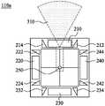
图2A为根据本发明内容的一些实施例所示出的第一极化天线模块110a的上视图。如图2A所示,该第一极化天线模块110a包含第一天线单元210、220、230、240、开关250、反射单元212、214、222、224、232、234、242、244,其中该反射单元212和该反射单元214设置于该第一天线单元210的两侧,该反射单元222和该反射单元224设置于该第一天线单元220的两侧,该反射单元232和该反射单元234设置于该第一天线单元230的两侧,该反射单元242和该反射单元244设置于该第一天线单元240的两侧,且所述第一天线单元210、220、230以及240分别与该开关250连接。FIG. 2A is a top view of the first polarized
于一些实施例中,所述第一天线单元210、220、230以及240为双频天线,其中双频包含2.4GHz和5GHz,但不限于此,任何频率皆在本发明内容所保护的范围内。于一些实施例中,所述第一天线单元210、220、230以及240可以由平面倒F天线(Planar Inverted FAntenna,PIFA)、偶极(dipole)天线以及回路(Loop)天线来实现,但不限于此,任何适用于实现水平极化天线单元的电路元件皆在本发明内容所保护的范围内。In some embodiments, the
于一些实施例中,该开关250耦接至所述第一天线单元210、220、230和240,并依据不同状态进行切换,以导通所述第一天线单元210、220、230和240其中一者,使得导通的第一天线单元据以操作。于一些实施例中,该开关250可以由一对四开关或以上所实现,但不限于此,可以根据第一极化天线模块110a包含的第一天线单元的数量来设计该开关250的切换数量。In some embodiments, the
于一些实施例中,该反射单元212和该反射单元214用以调整该第一天线单元210对应的辐射场型,该反射单元222和该反射单元224用以调整该第一天线单元220对应的辐射场型,该反射单元232和该反射单元234用以调整该第一天线单元230对应的辐射场型,该反射单元242和该反射单元244用以调整该第一天线单元240对应的辐射场型,使得所述第一天线单元210、220、230、240的辐射场型各自均可具有指向性。In some embodiments, the
于一些实施例中,所述反射单元212、214、222、224、232、234、242以及244可以由直角三角形所实现,但不限于此,任何可以用来调整该第二天线单元对应的辐射场型,以达到集中辐射场型效果的形状的反射单元皆在本发明内容所保护的范围内。此外,于一些实施例中,所述反射单元212、214、222、224、232、234、242以及244的材质为金属条,但不限于此,任何可以利于反射且不会造成传输死角的材质皆在本发明内容所保护的范围内。In some embodiments, the reflecting
于一些实施例中,所述第一天线单元中的低频辐射部和其对应左侧的反射单元的距离d1为八分之一波长,而所述第一天线单元中的高频辐射部和其对应右侧的反射单元的距离d2为八分之一波长,但不限于此,任何距离皆在本发明内容所保护的范围内。举例而言,如图2A所示,该第一天线单元210的低频辐射部和其对应该反射单元214的距离为d1,该第一天线单元210的高频辐射部和其对应该反射单元212的距离为d2。于一些实施例中,距离d1可以是12~16毫米,距离d2可以是7~9毫米范围。In some embodiments, the distance d1 between the low-frequency radiation part in the first antenna unit and its corresponding left reflection unit is one-eighth wavelength, and the high-frequency radiation part in the first antenna unit and The distance d2 corresponding to the reflection unit on the right side is one-eighth wavelength, but not limited thereto, any distance is within the protection scope of the present disclosure. For example, as shown in FIG. 2A , the distance between the low frequency radiation part of the
于一些实施例中,所述反射单元212、214、222、224、232、234、242以及244没有接地,并且所述反射单元212、214、222、224、232、234、242以及244和所述第一天线单元210、220、230、240对应一者的夹角θ1,但不限于此,所述反射单元212、214、222、224、232、234、242以及244和所述第一天线单元210、220、230、240对应一者之间任何角度的夹角皆在本发明内容所保护的范围内。举例而言,如图2A所示,反射单元212和第一天线单元210之间的角度为夹角θ1。于一些实施例中夹角θ1可以是30~45度。In some embodiments, the
图2B为根据本发明内容的一些实施例所示出的第一极化天线模块110b的上视图。如图2B所示,该第一极化天线模块110b包含所述第一天线单元210、220、230、240、该开关250、反射单元212a、214a、222a、224a、232a、234a、242a、244a,其中所述反射单元212a、214a、222a、224a、232a、234a、242a、244a的反射面的形状为圆弧状,且材质与图2A中的所述反射单元212、214、222、224、232、234、242、244相同。2B is a top view of the first
图3为根据本发明内容的一些实施例所示出图2A中该第一极化天线模块110a的操作示意图。如图3所示,于一些实施例中,当该开关250切换使得该第一天线单元210启动时,所述第一天线单元220、230和240则关闭,于此状态下,该第一极化天线模块110a通过该第一天线单元210与该反射板212、214的协同操作,会产生如图3往上方传递的波束310,且于一些实施例中,此波束310的频率为2.4GHz或5GHz。FIG. 3 is a schematic diagram illustrating the operation of the first
类似地,当该开关250切换使得该第一天线单元220启动时,则所述第一天线单元210、230和240则关闭,于此状态下,该第一极化天线模块110a通过该第一天线单元220与该反射板222、224的协同操作,会产生如图3往左方传递的波束(图未示),且于一些实施例中,此波束的频率为2.4GHz或5GHz;当该开关250切换使得该第一天线单元230启动时,则所述第一天线单元210、220和240则关闭,于此状态下,该第一极化天线模块110a通过该第一天线单元230与反射单元232、234的协同操作,会产生如图3往下方传递的波束(图未示),且于一些实施例中,此波束的频率为2.4GHz或5GHz;当该开关250切换使得第一天线单元240启动时,则所述第一天线单元210、220和230则关闭,于此状态下,该第一极化天线模块110a通过该第一天线单元240与反射单元242、244的协同操作,会产生如图3往右方传递的波束(图未示),且于一些实施例中,此波束的频率为2.4GHz或5GHz的波束。Similarly, when the
于一些实施例中,图2B中该第一极化天线模块110b的操作方式与图2A中该第一极化天线模块110a的操作方式皆相同,于此将不再赘述。In some embodiments, the operation mode of the first
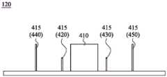
图4A为根据本发明内容的一些实施例所示出的第二极化天线模块120的侧视图。如图4A所示,于一些实施例中,该第二极化天线模块120包含第二天线单元410和多个第二反射单元415,其中所述第二反射单元415包含反射板420、430、440以及450。于一些实施例中,该反射板420和该反射板440设置于该第二天线单元410的第一侧,该反射板430和反射板450设置在该第二天线单元410相对于第一侧的第二侧。于一些实施例中,该第二极化天线模块120包含四个反射板,但不限于此,任何双数且设置于相对该第二天线单元的两侧的反射板皆在本发明内容所保护的范围内。FIG. 4A is a side view of the second
于一些实施例中,该第二天线单元410操作于双频之下,其中双频可以包含2.4GHz和5GHz,但不限于此,任何频率皆在本发明内容所保护的范围内。于一些实施例中,该第二天线单元410可以由平面倒F天线(Planar Inverted F Antenna,PIFA)、回路(Loop)天线以及开放回路(Open Loop)来实现,但不限于此,任何适用于实现垂直极化天线单元的电路元件皆在本发明内容所保护的范围内。In some embodiments, the
于一些实施例中,该反射板420和该反射板430的高度相同,该反射板440和该反射板450的高度相同,并且高于该反射板420和该反射板430。于一些实施例中,反射板440的高度为该反射板420的高度的两倍,但不限于此,任何可以用以调整该第二天线单元410的辐射场型的反射板高度皆在本发明内容所保护的范围内。于一些实施例中,反射板的高度须高于对应天线的高度,举例而言,该反射板420的高度需大于该第二天线单元410的高频辐射部的高度,该反射板440的高度需大于该第二天线单元410的低频辐射部的高度。In some embodiments, the
于一些实施例中,该反射板可以由线宽为3毫米至5毫米的细金属条所实现,但不限于此,任何可以用以实现调整辐射场型的反射板皆在本发明内容所保护的范围内。In some embodiments, the reflector can be realized by thin metal strips with a line width of 3 mm to 5 mm, but not limited to this, any reflector that can be used to adjust the radiation pattern is protected by the content of the present invention. In the range.
图4B为根据本发明内容的一些实施例所示出的第二极化天线模块120的上视图。如图4B所示,于一些实施例中,该第二极化天线模块120还包含开关462、464、466以及468,其中该开关462耦接至反射板440,该开关464耦接至该反射板420,该开关466耦接至该反射板430,该开关468耦接至该反射板450。于一些实施例中,所述开关462、464、466以及468耦接至一电子芯片,以控制所述多个开关切断或导通对应的反射板,举例而言,电子芯片控制该开关462以切断或导通与反射板440的连接。FIG. 4B is a top view of the second
于实际应用中,当该开关切断使得反射板和电子芯片不导通时,反射板的作用为导向器(Director),相较之下,当该开关导通使得反射板和电子芯片导通时,反射板的作用为反射器(Reflector)。于一些实施例中,所述开关462、464、466以及468可以由二极管所实现,但不限于此,任何可以用来实现切断或导通反射板的电子元件皆在本发明内容所保护的范围内。In practical applications, when the switch is turned off so that the reflector and the electronic chip are not connected, the reflector acts as a director. In contrast, when the switch is turned on, the reflector and the electronic chip are turned on. , the role of the reflector as a reflector (Reflector). In some embodiments, the
于一些实施例中,该反射板420与该第二天线单元410的距离d3和该反射板430与该第二天线单元410的距离d4相同,该反射板440与该第二天线单元410的距离d5和反射板450与该第二天线单元410的距离d6相同。于一些实施例中,该反射板420和该第二天线单元410的距离d3及该反射板430和该第二天线单元410的距离d4为高频应用频段中的八分之一波长至四分之一波长,该反射板440和该第二天线单元410的距离d5及该反射板450和该第二天线单元410的距离d6为低频应用频段中的八分之一波长至四分之一波长。举例而言,距离d3和距离d4的范围为7.5毫米至15毫米,距离d5和距离d6的范围为15.6毫米至30毫米。In some embodiments, the distanced3 between the
图5A、图5B及图5C为根据本发明内容的一些实施例所示出图4B中该第二极化天线模块120的操作示意图。如图5A所示,于一些实施例中,当只有该开关464切换使得该反射板420启动时,该第二极化天线模块120通过该第二天线单元410与该反射板420的协同操作,会产生如图5A右方传递的波束510,且于一些实施例中,此波束510的频率为5GHz。如图5B所示,于一些实施例中,当只有该开关466切换使得反射板430启动时,该第二极化天线模块120通过该第二天线单元410与反射板430的协同操作,会产生如图5B往左方传递的波束520,且于一些实施例中,此波束520的频率为5GHz。如图5C所示,于一些实施例中,当该开关464切换使得反射板420启动以及该开关466切换使得反射板430启动时,该第二极化天线模块120通过该第二天线单元410与反射板420、430的协同操作,会产生如图5C往上方传递的波束530以及如图5C往下方传递的波束540,且于一些实施例中,所述波束530和540的频率为5GHz。5A , 5B and 5C are schematic diagrams illustrating the operation of the second
类似地,当只有该开关462切换使得该反射板440启动时,该第二极化天线模块120通过该第二天线单元410与该反射板440的协同操作,会产生如图5A往右方传递的波束(图未示),且于一些实施例中,此波束的频率为2.4GHz;当只有该开关468切换使得反射板450启动时,该第二极化天线模块120通过该第二天线单元410与该反射板450的协同操作,会产生图5B往左方传递的波束(图未示),且于一些实施例中,此波束的频率为2.4GHz;当该开关462以及该开关468同时导通反射板440及反射板450时,该第二极化天线模块120通过第二天线单元410与反射板440、450的协同操作,会产生图5C往上方和下方传递的波束(图未示),且于一些实施例中,此上下波束的频率为2.4GHz。Similarly, when only the
于实际应用中,当检测到使用者进入某特定波束涵盖区(Beam Footprint)时,切换天线系统100的多个开关,以调整波束指向使用者,使得接收信号强度指标(ReceivedSignal Strength Indicator,RSSI)达到最大。In practical applications, when it is detected that the user enters a certain beam footprint (Beam Footprint), multiple switches of the
综上所述,本发明内容经由结合两种不同设计概念的天线模块于一个系统中,并操作在不同频率之下,以实现波束切换的功能,且兼具垂直和水平极化的双极化特性。In summary, the present invention realizes the function of beam switching by combining two antenna modules with different design concepts in one system and operating at different frequencies, and has dual polarization of vertical and horizontal polarization. characteristic.
虽然本发明内容已以实施方式公开如上,然其并非用以限定本发明内容,任何本领域技术人员,于不脱离本发明内容的构思和范围内,当可作各种的变动与润饰,因此本发明内容的保护范围当视权利要求所界定者为准。Although the content of the present invention has been disclosed in the above embodiments, it is not intended to limit the content of the present invention. Any person skilled in the art can make various changes and modifications without departing from the concept and scope of the content of the present invention. Therefore, The protection scope of the content of the present invention shall be determined by the claims defined.
Claims (10)
Priority Applications (2)
| Application Number | Priority Date | Filing Date | Title |
|---|---|---|---|
| CN201711065682.4ACN109755745B (en) | 2017-11-02 | 2017-11-02 | Antenna system |
| US15/922,352US10505284B2 (en) | 2017-11-02 | 2018-03-15 | Antenna system |
Applications Claiming Priority (1)
| Application Number | Priority Date | Filing Date | Title |
|---|---|---|---|
| CN201711065682.4ACN109755745B (en) | 2017-11-02 | 2017-11-02 | Antenna system |
Publications (2)
| Publication Number | Publication Date |
|---|---|
| CN109755745A CN109755745A (en) | 2019-05-14 |
| CN109755745Btrue CN109755745B (en) | 2020-10-09 |
Family
ID=66244355
Family Applications (1)
| Application Number | Title | Priority Date | Filing Date |
|---|---|---|---|
| CN201711065682.4AActiveCN109755745B (en) | 2017-11-02 | 2017-11-02 | Antenna system |
Country Status (2)
| Country | Link |
|---|---|
| US (1) | US10505284B2 (en) |
| CN (1) | CN109755745B (en) |
Families Citing this family (7)
| Publication number | Priority date | Publication date | Assignee | Title |
|---|---|---|---|---|
| CN110034400A (en)* | 2018-01-05 | 2019-07-19 | 台达电子工业股份有限公司 | Antenna assembly and antenna system |
| TWI671951B (en)* | 2018-03-09 | 2019-09-11 | 啟碁科技股份有限公司 | Smart antenna device |
| KR102573221B1 (en)* | 2018-10-25 | 2023-08-31 | 현대자동차주식회사 | Antenna and vehicle including the same |
| US10797408B1 (en)* | 2019-04-18 | 2020-10-06 | Huawei Technologies Co., Ltd. | Antenna structure and method for manufacturing the same |
| JP7413672B2 (en)* | 2019-07-25 | 2024-01-16 | 日本電気株式会社 | Antenna devices, radio transmitters, radio receivers, and radio communication systems |
| CN212162060U (en)* | 2020-06-24 | 2020-12-15 | 京信通信技术(广州)有限公司 | High-frequency radiation unit, multi-frequency coaxial radiation device and antenna |
| CN112615159B (en)* | 2020-12-09 | 2021-09-07 | 清华大学 | An Airborne Vertically Polarized and Dual-Polarized Phased Array |
Citations (3)
| Publication number | Priority date | Publication date | Assignee | Title |
|---|---|---|---|---|
| US7605758B2 (en)* | 2005-05-13 | 2009-10-20 | Go Net Systems Ltd. | Highly isolated circular polarized antenna |
| CN101783696A (en)* | 2009-01-20 | 2010-07-21 | 广升运有限公司 | Interference-free antenna module and WiFi network system using same |
| CN106450797A (en)* | 2015-08-06 | 2017-02-22 | 启碁科技股份有限公司 | Antenna system |
Family Cites Families (13)
| Publication number | Priority date | Publication date | Assignee | Title |
|---|---|---|---|---|
| TWM267648U (en) | 2004-04-01 | 2005-06-11 | Smart Ant Telecom Co Ltd | Intelligent antenna system with wave beam switching |
| EP2165388B1 (en)* | 2007-06-13 | 2018-01-17 | Intel Corporation | Triple stagger offsetable azimuth beam width controlled antenna for wireless network |
| TWI346420B (en) | 2007-09-20 | 2011-08-01 | Delta Networks Inc | Printed monopole smart antenna apply to wlan ap/router |
| US8693970B2 (en) | 2009-04-13 | 2014-04-08 | Viasat, Inc. | Multi-beam active phased array architecture with independant polarization control |
| US8666450B2 (en)* | 2010-05-09 | 2014-03-04 | Ralink Technology Corp. | Antenna and multi-input multi-output communication device using the same |
| TWI513105B (en) | 2012-08-30 | 2015-12-11 | Ind Tech Res Inst | Dual frequency coupling feed antenna, cross-polarization antenna and adjustable wave beam module |
| CN103606759A (en) | 2013-11-29 | 2014-02-26 | 电子科技大学 | Dual-mode antenna with wave beam direction switchable |
| CN105990682B (en)* | 2015-02-04 | 2019-05-14 | 启碁科技股份有限公司 | Microstrip antenna transceiver |
| US9263798B1 (en)* | 2015-04-30 | 2016-02-16 | Adant Technologies, Inc. | Reconfigurable antenna apparatus |
| CN105552575A (en) | 2015-12-15 | 2016-05-04 | 福建星网锐捷网络有限公司 | Antenna and antenna control method and device |
| CN106299728A (en)* | 2016-09-29 | 2017-01-04 | 上海航天测控通信研究所 | A kind of multipolarization is switched fast antenna array |
| TWM537317U (en) | 2016-10-28 | 2017-02-21 | 鋐寶科技股份有限公司 | Smart antenna system capable of switching polarization direction |
| CN106785371A (en)* | 2017-01-03 | 2017-05-31 | 华南理工大学 | Broadband base station antenna |
- 2017
- 2017-11-02CNCN201711065682.4Apatent/CN109755745B/enactiveActive
- 2018
- 2018-03-15USUS15/922,352patent/US10505284B2/enactiveActive
Patent Citations (3)
| Publication number | Priority date | Publication date | Assignee | Title |
|---|---|---|---|---|
| US7605758B2 (en)* | 2005-05-13 | 2009-10-20 | Go Net Systems Ltd. | Highly isolated circular polarized antenna |
| CN101783696A (en)* | 2009-01-20 | 2010-07-21 | 广升运有限公司 | Interference-free antenna module and WiFi network system using same |
| CN106450797A (en)* | 2015-08-06 | 2017-02-22 | 启碁科技股份有限公司 | Antenna system |
Non-Patent Citations (1)
| Title |
|---|
| LTE室分方案及建设策略;涂志刚;《通讯世界》;20170425;第84-85页* |
Also Published As
| Publication number | Publication date |
|---|---|
| US10505284B2 (en) | 2019-12-10 |
| CN109755745A (en) | 2019-05-14 |
| US20190131720A1 (en) | 2019-05-02 |
Similar Documents
| Publication | Publication Date | Title |
|---|---|---|
| CN109755745B (en) | Antenna system | |
| CN103606757B (en) | A kind of dual-band dual-polarized antenna battle array | |
| TWI634700B (en) | Communication device | |
| TWI639275B (en) | Communication device | |
| Ko et al. | A compact dual-band pattern diversity antenna by dual-band reconfigurable frequency-selective reflectors with a minimum number of switches | |
| CN103390795B (en) | A kind of directional diagram has the antenna of multiple restructural characteristic | |
| TWI628862B (en) | Communication device | |
| CN103098304B (en) | Dual-band dual-polarized antenna | |
| JP6984019B2 (en) | Antenna array and wireless communication device | |
| CN115084873A (en) | Dual-polarization 1-bit antenna based on electromagnetic metamaterial and digital bit array | |
| CN104659489A (en) | Antenna device with large coverage area | |
| CN110034400A (en) | Antenna assembly and antenna system | |
| CN107394346A (en) | Communication device | |
| CN109149080B (en) | communication device | |
| TWI685147B (en) | Antenna system | |
| CN110112565A (en) | Antenna system and Anneta module | |
| US11978963B2 (en) | Beam diversity by smart antenna with passive elements | |
| US12068543B2 (en) | Beam diversity by smart antenna without passive elements | |
| TW201935771A (en) | Antenna system and antenna module | |
| Wang et al. | A Low-Profile Vertically Polarized Beam Switchable Antenna for FTTR Applications | |
| CN108242586B (en) | communication device | |
| TWM260009U (en) | Dual-polarization dipole antenna | |
| CN119171081A (en) | Antenna and electronic equipment | |
| KR20130026089A (en) | Wi-fi band switched parasitic active beam forming antenna | |
| TW201931675A (en) | Antenna device and antenna system |
Legal Events
| Date | Code | Title | Description |
|---|---|---|---|
| PB01 | Publication | ||
| PB01 | Publication | ||
| SE01 | Entry into force of request for substantive examination | ||
| SE01 | Entry into force of request for substantive examination | ||
| TA01 | Transfer of patent application right | Effective date of registration:20190701 Address after:Chinese Taiwan Taoyuan City Applicant after:Delta Optoelectronics Inc. Address before:Chinese Taiwan Taoyuan City Applicant before:Dachuang Science and Technology Co., Ltd. | |
| TA01 | Transfer of patent application right | ||
| GR01 | Patent grant | ||
| GR01 | Patent grant |