CN109730777B - A soft robot for intraoperative cardiac tissue assisted fixation - Google Patents
A soft robot for intraoperative cardiac tissue assisted fixationDownload PDFInfo
- Publication number
- CN109730777B CN109730777BCN201811629820.1ACN201811629820ACN109730777BCN 109730777 BCN109730777 BCN 109730777BCN 201811629820 ACN201811629820 ACN 201811629820ACN 109730777 BCN109730777 BCN 109730777B
- Authority
- CN
- China
- Prior art keywords
- hardened
- adsorption
- air passage
- shaped
- rigid
- Prior art date
- Legal status (The legal status is an assumption and is not a legal conclusion. Google has not performed a legal analysis and makes no representation as to the accuracy of the status listed.)
- Expired - Fee Related
Links
- 210000005003heart tissueAnatomy0.000titleclaimsabstractdescription34
- 238000001179sorption measurementMethods0.000claimsabstractdescription124
- 239000011664nicotinic acidSubstances0.000claimsabstractdescription33
- 238000006243chemical reactionMethods0.000claimsabstractdescription27
- 238000005516engineering processMethods0.000claimsabstractdescription9
- 2380000101463D printingMethods0.000claimsabstractdescription7
- 238000000605extractionMethods0.000claimsabstractdescription6
- 239000002245particleSubstances0.000claimsdescription17
- 239000007779soft materialSubstances0.000claimsdescription16
- 239000007787solidSubstances0.000claimsdescription16
- 238000002955isolationMethods0.000claimsdescription13
- 239000000463materialSubstances0.000claimsdescription11
- 238000004891communicationMethods0.000claimsdescription9
- 238000003491arrayMethods0.000claimsdescription8
- 241000238413OctopusSpecies0.000claimsdescription3
- 210000000078clawAnatomy0.000claimsdescription3
- 230000002784sclerotic effectEffects0.000claims1
- 230000006378damageEffects0.000abstractdescription6
- 238000013461designMethods0.000abstractdescription5
- 238000001356surgical procedureMethods0.000abstractdescription5
- 238000000465mouldingMethods0.000abstractdescription3
- 238000004519manufacturing processMethods0.000abstractdescription2
- 238000010586diagramMethods0.000description9
- 238000000034methodMethods0.000description8
- 210000004351coronary vesselAnatomy0.000description5
- 230000000747cardiac effectEffects0.000description3
- 208000029078coronary artery diseaseDiseases0.000description3
- 210000001519tissueAnatomy0.000description3
- 230000003872anastomosisEffects0.000description2
- 230000000694effectsEffects0.000description2
- 230000007246mechanismEffects0.000description2
- 210000004165myocardiumAnatomy0.000description2
- 238000003908quality control methodMethods0.000description2
- 238000011160researchMethods0.000description2
- 206010005746Blood pressure fluctuationDiseases0.000description1
- 208000009447Cardiac EdemaDiseases0.000description1
- 206010019280Heart failuresDiseases0.000description1
- 208000027418Wounds and injuryDiseases0.000description1
- 230000009286beneficial effectEffects0.000description1
- 210000004204blood vesselAnatomy0.000description1
- 238000011161developmentMethods0.000description1
- 238000001125extrusionMethods0.000description1
- 230000005021gaitEffects0.000description1
- 230000010247heart contractionEffects0.000description1
- 208000014674injuryDiseases0.000description1
- 208000031225myocardial ischemiaDiseases0.000description1
- 210000000056organAnatomy0.000description1
- 230000002980postoperative effectEffects0.000description1
- 230000001225therapeutic effectEffects0.000description1
- 230000009466transformationEffects0.000description1
Images


Landscapes
- Manipulator (AREA)
Abstract
Translated fromChinese
Description
Translated fromChinese技术领域technical field
本发明涉及医疗机器人领域,尤其涉及一种用于术中心脏组织辅助固定的软体机器人。The invention relates to the field of medical robots, in particular to a soft robot used for assisted fixation of intraoperative cardiac tissue.
背景技术Background technique
非体外循环冠状动脉搭桥术可显著改善心肌缺血、最大限度的避免设备对患者各脏器造成的损伤,在治疗重症冠心病方面效果显著。但是,为了达到良好的治疗效果,必须采用有效的技术和仪器对患者进行精确的检测,并借助先进的手术器械完成手术。Off-pump coronary artery bypass grafting can significantly improve myocardial ischemia, avoid equipment damage to various organs of patients to the greatest extent, and has a significant effect in the treatment of severe coronary heart disease. However, in order to achieve a good therapeutic effect, effective techniques and instruments must be used to accurately detect the patient, and the operation must be completed with the help of advanced surgical instruments.
心脏固定器是非体外循环冠状动脉搭桥手术中必不可少的装置,它可以保证在心脏跳动情况下,其所固定的局部手术操作区域相对稳定,为微小血管吻合提供保障。但是,现有心脏固定器所提供的吸附力较为固定且需要手工调整,为了维持手术视野的稳定清晰,医生通常忽视患者心肌所能承受的压力进行固定,容易造成患者术后心脏固定区域出现心肌损伤、心脏水肿、心功能不全等。同时现有可调机械臂式固定器对心脏位置的调整幅度有限,固定后机械臂对心脏的固定生硬,导致桥血管吻合过程中血压变化较大,可能引起脑血管并发症等,手术风险大幅提高。Cardiac fixator is an indispensable device in off-pump coronary artery bypass surgery. It can ensure that the fixed local operation area is relatively stable under the condition of heart beating, and provides guarantee for the anastomosis of small blood vessels. However, the adsorption force provided by the existing cardiac fixator is relatively fixed and needs to be adjusted manually. In order to maintain a stable and clear surgical field of view, doctors usually ignore the pressure that the patient's myocardium can bear for fixation, which may easily lead to the occurrence of myocardium in the patient's post-operative cardiac fixation area. Injury, cardiac edema, cardiac insufficiency, etc. At the same time, the existing adjustable mechanical arm fixator can adjust the position of the heart to a limited extent. After fixation, the fixation of the mechanical arm to the heart is rigid, resulting in a large change in blood pressure during the anastomosis of the bridge vessel, which may cause cerebrovascular complications, etc., and the surgical risk is large. improve.
基于刚性机构的机器人广泛应用于医疗领域各类手术,但这类机器人的灵活性、适应性和安全性差,容易造成人体组织损伤。近年来,采用软性材料制作而成软体机器人,能够柔软连续地变形适应各类组织结构,通过气动等方式实现软体机构的动作及转换,可显著提高手术机器人系统的适应性和安全性。软体机器人技术作为一项新兴的前沿技术迅速发展,逐渐在医疗领域得到应用,已成为手术机器人技术的重要发展方向。Robots based on rigid mechanisms are widely used in various surgeries in the medical field, but such robots have poor flexibility, adaptability, and safety, and are prone to damage to human tissue. In recent years, soft robots are made of soft materials, which can deform softly and continuously to adapt to various tissue structures, and realize the movement and transformation of the soft body through pneumatics and other methods, which can significantly improve the adaptability and safety of the surgical robot system. As an emerging cutting-edge technology, soft robotics has developed rapidly and has gradually been applied in the medical field, and has become an important development direction of surgical robotics.
发明内容SUMMARY OF THE INVENTION
本发明的目的是提供一种具有多通道切换和多功能的柔性吸附心脏辅助固定软体机器人,可根据环境需要进行步态的状态切换和功能实现。。The purpose of the present invention is to provide a flexible adsorption heart-assisted fixation soft robot with multi-channel switching and multi-function, which can perform state switching and function realization of gait according to the needs of the environment. .
为实现上述发明目的,本发明的技术方案是:一种用于术中心脏组织辅助固定的软体机器人,包括:In order to achieve the above-mentioned purpose of the invention, the technical scheme of the present invention is: a soft robot for assisted fixation of intraoperative cardiac tissue, comprising:
用于辅助固定心脏组织的U型吸附结构,所述U型吸附结构包括两组仿生吸盘阵列、U型结构主体、硬化隔离板、吸附结构连接件;A U-shaped adsorption structure for assisting the fixation of cardiac tissue, the U-shaped adsorption structure includes two groups of bionic suction cup arrays, a U-shaped structure main body, a hardened isolation plate, and an adsorption structure connector;
所述仿生吸盘阵列包括呈线性阵列分布在吸盘安装块上的若干仿生吸盘;所述吸盘安装块内部设有第一硬化气道,及与所述仿生吸盘相连的第一吸附气道;The bionic suction cup array includes a plurality of bionic suction cups distributed on the suction cup mounting block in a linear array; the suction cup mounting block is provided with a first hardened air passage and a first adsorption air passage connected with the bionic suction cup;
所述U型结构主体开口方向的两端部分别安装所述仿生吸盘阵列;所述U型结构主体内设有第二硬化气道、第二吸附气道,所述第二硬化气道的两个入口、与所述第二吸附气道的一个入口均设置在所述U型结构主体闭合的端部,所述第二硬化气道的两个出口,及所述第二吸附气道的两个出口分布在所述U型结构主体开口方向的两端部;所述第二硬化气道、第二吸附气道分别与所述第一硬化气道、第一吸附气道气密导通;The bionic suction cup arrays are respectively installed at both ends of the U-shaped structure main body in the opening direction; the U-shaped structure main body is provided with a second hardened air passage and a second adsorption air passage, and two of the second hardened air passages are provided. The two inlets and the one inlet of the second adsorption air passage are all arranged at the closed end of the U-shaped structure body, the two outlets of the second hardened air passage, and the two outlets of the second adsorption air passage. The outlets are distributed at both ends of the main body of the U-shaped structure in the opening direction; the second hardened air passage and the second adsorption air passage are airtightly connected to the first hardened air passage and the first adsorption air passage respectively;
所述第一硬化气道、第二硬化气道内填充固体硬化颗粒;The first hardened air passage and the second hardened air passage are filled with solid hardened particles;
所述硬化隔离板安装在所述U型结构主体闭合的端部,所述硬化隔离板中部设有第三吸附气道,所述第三吸附气道两侧分别设有第三硬化气道;所述第三吸附气道与所述第二吸附气道的入口气密导通,两条第三硬化气道分别与所述第二硬化气道的两个入口气密导通;The hardened isolation plate is installed at the closed end of the U-shaped structure main body, the middle of the hardened isolation plate is provided with a third adsorption air passage, and the third hardened air passages are respectively provided on both sides of the third adsorption air passage; The third adsorption air passage is in airtight communication with the inlet of the second adsorption air passage, and the two third hardened air passages are airtightly connected with the two inlets of the second hardened air passage respectively;
所述吸附结构连接件包括圆头端和矩形端,所述矩形端与所述硬化隔离板连接;所述吸附结构连接件中部设有第四吸附气道,所述第四吸附气道两侧分别设有第四硬化气道;所述第四吸附气道与所述第三吸附气道气密导通,两条第四硬化气道分别与两条第三硬化气道气密导通;The adsorption structure connector includes a round head end and a rectangular end, and the rectangular end is connected with the hardened isolation plate; a fourth adsorption air channel is arranged in the middle of the adsorption structure connector, and two sides of the fourth adsorption air channel are arranged. A fourth hardened air passage is respectively provided; the fourth adsorption air passage is airtightly connected to the third adsorption air passage, and the two fourth hardened air passages are respectively airtightly connected to the two third hardened air passages;
与所述吸附结构连接件圆头端连接的刚柔转换支撑臂,用于U型吸附结构的支撑,U型吸附结构内部气体的抽取和输送;所述刚柔转换支撑臂中部设有硬化腔道,硬化腔道中心设有第五吸附气道,所述硬化腔道直径大于第五吸附气道外径,第五吸附气道外的硬化腔道内填充固体硬化颗粒;所述刚柔转换支撑臂内还设有两条第五硬化气道,两条第五硬化气道沿刚柔转换支撑臂的同一直径分设在硬化腔道的两侧;所述第五吸附气道与所述第四吸附气道气密导通,两条第五硬化气道分别与两条第四硬化气道气密导通;The rigid-flexible conversion support arm connected with the round head end of the adsorption structure connector is used for the support of the U-shaped adsorption structure, and the extraction and transportation of the gas inside the U-shaped adsorption structure; the middle of the rigid-flexible conversion support arm is provided with a hardening cavity The center of the hardening channel is provided with a fifth adsorption air channel, the diameter of the hardening channel is larger than the outer diameter of the fifth adsorption air channel, and the hardening channel outside the fifth adsorption air channel is filled with solid hardened particles; There are also two fifth hardened air passages, and the two fifth hardened air passages are respectively arranged on both sides of the hardened cavity along the same diameter of the rigid-flexible conversion support arm; the fifth adsorption air passage and the fourth adsorption air passage The two fifth hardened airways are airtightly connected to the two fourth hardened airways respectively;
安装在所述刚柔转换支撑臂末端的尾端连接结构,所述尾端连接结构中心设有第六吸附气道,所述尾端连接结构内还设有两条第六硬化气道、两条支撑臂硬化气道,所述第六吸附气道与所述第五吸附气道气密导通,两条第六硬化气道与两条第五硬化气道气密导通,两条支撑臂硬化气道与所述硬化腔道气密导通。The tail end connection structure installed at the end of the rigid-flexible conversion support arm, the center of the tail end connection structure is provided with a sixth adsorption air passage, and the tail end connection structure is also provided with two sixth hardened air passages, two One support arm hardened air passage, the sixth adsorption air passage is airtightly connected to the fifth adsorption air passage, the two sixth hardened air passages are airtightly connected to the two fifth hardened air passages, and the two support The arm hardening airway is in airtight communication with the hardening cavity.
优选的,所述仿生吸盘阵列包括4-5枚仿生章鱼爪吸盘,所述仿生吸盘利用3D打印技术,使用邵氏硬度为40A的软质材料制作。Preferably, the bionic suction cup array includes 4-5 bionic octopus claw suction cups, and the bionic suction cups are made of a soft material with a Shore hardness of 40A using 3D printing technology.
优选的,所述U型结构主体上还设有若干固体硬化颗粒入口。Preferably, the U-shaped structural body is further provided with a plurality of solid hardening particle inlets.
优选的,所述第五吸附气道、第五硬化气道具有沿轴向间隔布置软体材料和刚性材料的管壁。Preferably, the fifth adsorption air passage and the fifth hardened air passage have pipe walls in which the soft material and the rigid material are arranged at intervals along the axial direction.
优选的,所述第三硬化气道为蜂窝状腔道。Preferably, the third hardened air channel is a honeycomb channel.
优选的,所述硬化腔道横截面为沿所述刚柔转换支撑臂直径延伸的类长方形。Preferably, the cross section of the hardening channel is a rectangle-like shape extending along the diameter of the rigid-flexible conversion support arm.
本发明的有益效果是:The beneficial effects of the present invention are:
1.本发明U型吸附结构及仿生吸盘结构设计,可保证吸盘结构与心脏组织的充分接触和吸附固定作用,同时软硬度转换,可有效防止心脏组织的吸附损伤。1. The U-shaped adsorption structure and the bionic suction cup structure design of the present invention can ensure sufficient contact and adsorption and fixation between the suction cup structure and the heart tissue, and at the same time the softness and hardness are converted, which can effectively prevent the adsorption damage of the heart tissue.
2.本发明通过内置的气道分别作为仿生吸盘吸附腔道和结构硬化腔道,通过气动方式实现对心脏组织的柔性吸附和结构软硬态转换,驱动方式更加安全,气动方式结构简单,适用性较强。2. The present invention uses the built-in air channels as the bionic suction cup adsorption channel and the structural hardening channel respectively, and realizes the flexible adsorption of the cardiac tissue and the structural soft-hard state conversion through the pneumatic method. The driving method is safer, and the pneumatic method has a simple structure and is suitable for use. Strong sex.
3.本发明所设计的柔性支撑臂设计两路固体颗粒硬化腔道和一路负压气道,主体采用软体材料制作,两路硬化腔道采用软体材料和硬质材料分节连接的设计方式,可解决常压下的柔性变形和真空硬化下刚性支撑问题,保证软体机器人在抽负压时气道的完整性。3. The flexible support arm designed by the present invention is designed with two solid particle hardening cavities and one negative pressure air channel, the main body is made of soft material, and the two hardening cavities are designed by connecting the soft material and the hard material in sections, It can solve the problem of flexible deformation under normal pressure and rigid support under vacuum hardening, and ensure the integrity of the airway of the soft robot when the negative pressure is pumped.
4.本发明结构简单,所有部件均可采用3D打印精密成型技术,易于制造,成本较低。4. The structure of the present invention is simple, and all parts can adopt 3D printing precision molding technology, which is easy to manufacture and has low cost.
附图说明Description of drawings
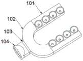
图1为本发明实施例一种用于术中心脏组织辅助固定的软体机器人的结构示意图;1 is a schematic structural diagram of a soft robot for intraoperative assisted fixation of cardiac tissue according to an embodiment of the present invention;
图2为本发明实施例一种用于术中心脏组织辅助固定的软体机器人的U型吸附结构1的结构示意图;2 is a schematic structural diagram of a U-shaped adsorption structure 1 of a soft robot for intraoperative cardiac tissue assisted fixation according to an embodiment of the present invention;
图3为本发明实施例一种用于术中心脏组织辅助固定的软体机器人的仿生吸盘阵列101的结构示意图;3 is a schematic structural diagram of a bionic
图4为本发明实施例一种用于术中心脏组织辅助固定的软体机器人的U型结构主体102的结构示意图1;4 is a schematic structural diagram 1 of a U-shaped structural
图5为本发明实施例一种用于术中心脏组织辅助固定的软体机器人的U型结构主体102的结构示意图2;5 is a schematic structural diagram 2 of a U-shaped structural
图6为本发明实施例一种用于术中心脏组织辅助固定的软体机器人的硬化隔离板1033的结构示意图;6 is a schematic structural diagram of a hardened isolation plate 1033 of a soft robot for intraoperative cardiac tissue assisted fixation according to an embodiment of the present invention;
图7为本发明实施例一种用于术中心脏组织辅助固定的软体机器人的吸附结构连接件104的结构示意图;FIG. 7 is a schematic structural diagram of an
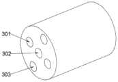
图8为本发明实施例一种用于术中心脏组织辅助固定的软体机器人的刚柔转换支撑臂2的结构示意图;8 is a schematic structural diagram of a rigid-flexible
图9为本发明实施例一种用于术中心脏组织辅助固定的软体机器人的尾端连接结构3的结构示意图。FIG. 9 is a schematic structural diagram of a tail end connecting structure 3 of a soft robot for intraoperative assisted fixation of cardiac tissue according to an embodiment of the present invention.
此处的附图被并入说明书中并构成本说明书的一部分,示出了符合本发明的实施例,并与说明书一起用于解释本发明的原理。The accompanying drawings, which are incorporated in and constitute a part of this specification, illustrate embodiments consistent with the invention and together with the description serve to explain the principles of the invention.
具体实施方式Detailed ways
下面将结合附图对本发明实施例中的技术方案进行清楚、完整地描述。The technical solutions in the embodiments of the present invention will be clearly and completely described below with reference to the accompanying drawings.
如图1-2所示,本发明实施例的一种用于术中心脏组织辅助固定的软体机器人,包括:As shown in Figures 1-2, a soft robot for intraoperative cardiac tissue assisted fixation according to an embodiment of the present invention includes:
用于辅助固定心脏组织的U型吸附结构1,所述U型吸附结构1包括两组仿生吸盘阵列101、U型结构主体102、硬化隔离板103、吸附结构连接件104。A U-shaped adsorption structure 1 for assisting in fixing heart tissue, the U-shaped adsorption structure 1 includes two groups of bionic
如图3所示,本发明实施例的所述仿生吸盘阵列101包括呈线性阵列分布在吸盘安装块上的4-5枚仿生吸盘;优选的,采用4枚仿生章鱼爪吸盘,仿生吸盘材质为邵氏硬度为35-40A的软质材料,利用3D打印技术。As shown in FIG. 3 , the bionic
优选的,吸盘安装块1011与U型结构主体102均采用软质材料的3D打印技术制作,其中软质材料邵氏硬度在35-40A,质地柔软,不会损失心脏组织。Preferably, both the suction
为了进一步提高吸附效果,吸盘安装座1011上表面设计为阶梯面1015,阶梯面1015带有自中心向外逐渐加深的坡面,仿生吸盘1012均安装在坡面上;两组仿生吸盘阵列101安装时,将吸盘安装座1011的坡面向内相对,则两组仿生吸盘1012均向心倾斜,能够给心脏组织提供更贴合的接触承托面。In order to further improve the adsorption effect, the upper surface of the suction
进一步,吸盘安装座1011上表面加工成弧面,仿生吸盘1012安装后,呈现碗状接触承托面。Further, the upper surface of the suction
所述吸盘安装块1011内部设有第一硬化气道1013,及与所述仿生吸盘1012相连的第一吸附气道1014;The suction
如图2、4、5所示,本发明实施中U型结构主体102开口方向的两端部分别安装所述仿生吸盘阵列101;所述U型结构主体102内设有第二硬化气道1021、第二吸附气道1022,所述第二硬化气道1021的两个入口1021a、与所述第二吸附气道1022的一个入口1022a均设置在所述U型结构主体102闭合的端部,所述第二硬化气道1021的两个出口1021b,及所述第二吸附气道1022的两个出口1022b分布在所述U型结构主体102开口方向的两端部;所述第二硬化气道1021、第二吸附气道1022分别与所述第一硬化气道1013、第一吸附气道1014气密导通;具体的,两个仿生吸盘阵列101的两条第一硬化气道1013分别连接在第二硬化气道1021的两个出口1021b上,两个仿生吸盘阵列101的两条第一吸附气道1014连接在第二吸附气道1022的两个出口1022b上。As shown in FIGS. 2 , 4 and 5 , in the implementation of the present invention, the bionic
优选的,所述第一硬化气道1013、第二硬化气道1021内填充固体硬化颗粒;Preferably, the first
第一吸附气道1014、第二吸附气道1022的管壁均采用软质材料与硬质材料结合,其中软质材料邵氏硬度在35-40A,硬质材料邵氏硬度在95-100A。The tube walls of the first
固体硬化颗粒和软硬结合的设计即可以使得气道随U型吸附结构1整体弯曲变形,又可以支撑整体结构,特别是在抽负压硬化时保持气道及整体结构的完整形状。The design of the solid hardened particles and the combination of soft and hard can not only make the airway bend and deform with the U-shaped adsorption structure 1 as a whole, but also support the whole structure, especially to maintain the complete shape of the airway and the whole structure when it is hardened by negative pressure.
优选的,在本实施中的U型结构主体102上还设有2-4个固体硬化颗粒入口1023a,固体硬化颗粒入口1023a自U型结构主体102表面向下通入第二硬化气道1021,用于向内气道填充固体硬化颗粒,填充后需随即密封。Preferably, 2-4 solid hardening particle inlets 1023a are further provided on the U-shaped structure
如图2、6所示,所述硬化隔离板103安装在所述U型结构主体102闭合的端部,本发明实施例中硬化隔离板103中部设有第三吸附气道1032,所述第三吸附气道1032两侧分别设有第三硬化气道1031;所述第三吸附气道1032与所述第二吸附气道1022的入口1022a气密导通,两条第三硬化气道1031分别与所述第二硬化气道1021的两个入口1021a气密导通;As shown in FIGS. 2 and 6 , the
为防止第一硬化气道1013、第二硬化气道1021中的固体硬化颗粒进入第三硬化气道1031,第三硬化气道1031采用孔径小于固体硬化颗粒直径的蜂窝状腔道。In order to prevent the solid hardened particles in the first
如图2、7所示,本发明实施中吸附结构连接件104包括圆头端1041和矩形端1042,圆角化的外形设计可以防止结构接触组织时产生损伤;所述矩形端1042与所述硬化隔离板103连接;所述吸附结构连接件104中部设有第四吸附气道1044,所述第四吸附气道1044两侧分别设有第四硬化气道1043;所述第四吸附气道1044与所述第三吸附气道1032气密导通,两条第四硬化气道1043分别与两条第三硬化气道1031气密导通。As shown in FIGS. 2 and 7 , in the implementation of the present invention, the
为了进一步保障U型吸附结构1具有足以维持自身形状的硬度,硬化隔离板103、吸附结构连接件104均采用邵氏硬度为100A的材料。In order to further ensure that the U-shaped adsorption structure 1 has sufficient hardness to maintain its own shape, the
如图1、8所示,本发明实施中与所述吸附结构连接件104圆头端1041连接的刚柔转换支撑臂2,用于U型吸附结构1的支撑,以及U型吸附结构1内部气体的抽取和输送。刚柔转换支撑臂的整体长度为150mm,最大外径为22mm、最小外径18mm。As shown in FIGS. 1 and 8 , in the implementation of the present invention, the rigid-flexible
刚柔转换支撑臂2中部设有硬化腔道201,硬化腔道201中心设有第五吸附气道203,第五吸附气道203通过机构固定连接孔204安装;所述硬化腔道201直径大于第五吸附气道203外径,所述刚柔转换支撑臂2内还设有两条第五硬化气道202,两条第五硬化气道202沿刚柔转换支撑臂2的同一直径分设在硬化腔道201的两侧;所述第五吸附气道203与所述第四吸附气道1044气密导通,两条第五硬化气道202分别与两条第四硬化气道1043气密导通;The rigid-flexible
刚柔转换支撑臂2整体采用软质材料制作,为了保证刚柔转换支撑臂2能够维持形状,并在抽负压时保持硬化,所述第五吸附气道203、第五硬化气道202具有沿轴向间隔布置软体材料和刚性材料的管壁,软体材料和硬质材料分节连接,软质材料的邵氏硬度为40A,硬质材料的邵氏硬度为100A,同时第五吸附气道203外的硬化腔道201内填充固体硬化颗粒。The rigid-flexible
优选的,将硬化腔道201加工成横截面为沿所述刚柔转换支撑臂2直径延伸的类长方形,增加固体硬化颗粒的填充空间。Preferably, the hardening
这样的设计方式不仅可以解决刚柔转换支撑臂2结构的的柔性变形和真空硬化下刚性支撑问题,还可以保证在气道抽真空时整个气道的完整性;支撑臂的空腔结构可以实现整个支撑臂的抽负压以及颗粒挤压硬化支撑。通过刚柔转换支撑臂2结构可以实现整个仿生软体机器人的柔性吸附、真空硬化固定和U型吸附结构1气体抽取和输送等功能。Such a design method can not only solve the flexible deformation of the rigid-flexible
如图1、9所示,本发明实施例中安装在所述刚柔转换支撑臂2末端的尾端连接结构3,所述尾端连接结构3中心设有第六吸附气道302,所述尾端连接结构3内还设有两条第六硬化气道301、两条支撑臂硬化气道303,所述第六吸附气道302与所述第五吸附气道203气密导通,两条第六硬化气道301与两条第五硬化气道202气密导通,两条支撑臂硬化气道303与所述硬化腔道201气密导通。As shown in FIGS. 1 and 9 , in the embodiment of the present invention, a tail end connecting structure 3 installed at the end of the rigid-flexible
该尾端连接结构3包含的五路气路气道,一路第六吸附气道302用于吸附固定时吸负压的连接供应,两路支撑臂硬化气道303用于支撑壁的柔性变形和真空硬化的气压供应,两路第六硬化气道301用于U型吸附结构1、刚柔转换支撑臂2硬化的负压供应。该尾端连接结构3采用硬质材料设计。真空抽取及正压输送所需正负压气路控制系统可采用空压机、真空泵(0-0.9MPa)、换向阀(GPR3008L,AirTac)、PLC控制器及其他辅助部件设计完成,并通过计算机编程控制。The tail end connection structure 3 includes five air passages, a sixth
整个软体机器人的结构可采用多材料3D打印一体化精密成型技术制作完成。该软体机器人可以实现冠脉搭桥手术中心脏组织的柔性吸附固定和智能调节,在有效固定心脏组织的同时防止产生吸附损伤,可为冠脉搭桥术精准质控和冠心病基础研究提供精准高效的新工具,全面提升冠脉搭桥术质控技术与仪器水平,并为冠心病学基础研究提供新颖的科学仪器。The structure of the entire soft robot can be completed by using multi-material 3D printing integrated precision molding technology. The soft robot can realize flexible adsorption fixation and intelligent adjustment of cardiac tissue in coronary artery bypass surgery, effectively fix cardiac tissue while preventing adsorption damage, and provide accurate and efficient methods for precise quality control of coronary artery bypass surgery and basic research on coronary heart disease. The new tool comprehensively improves the quality control technology and instrument level of coronary artery bypass grafting, and provides novel scientific instruments for the basic research of coronary heart disease.
所描述的实施例仅仅是本发明一部分实施例,而不是全部的实施例。基于本发明中的实施例,本领域普通技术人员在没有做出创造性劳动前提下所获得的所有其他实施例,都属于本发明保护的范围。The described embodiments are only some, but not all, embodiments of the present invention. Based on the embodiments of the present invention, all other embodiments obtained by those of ordinary skill in the art without creative efforts shall fall within the protection scope of the present invention.
Claims (6)
Translated fromChinesePriority Applications (1)
| Application Number | Priority Date | Filing Date | Title |
|---|---|---|---|
| CN201811629820.1ACN109730777B (en) | 2018-12-28 | 2018-12-28 | A soft robot for intraoperative cardiac tissue assisted fixation |
Applications Claiming Priority (1)
| Application Number | Priority Date | Filing Date | Title |
|---|---|---|---|
| CN201811629820.1ACN109730777B (en) | 2018-12-28 | 2018-12-28 | A soft robot for intraoperative cardiac tissue assisted fixation |
Publications (2)
| Publication Number | Publication Date |
|---|---|
| CN109730777A CN109730777A (en) | 2019-05-10 |
| CN109730777Btrue CN109730777B (en) | 2020-06-30 |
Family
ID=66362051
Family Applications (1)
| Application Number | Title | Priority Date | Filing Date |
|---|---|---|---|
| CN201811629820.1AExpired - Fee RelatedCN109730777B (en) | 2018-12-28 | 2018-12-28 | A soft robot for intraoperative cardiac tissue assisted fixation |
Country Status (1)
| Country | Link |
|---|---|
| CN (1) | CN109730777B (en) |
Families Citing this family (3)
| Publication number | Priority date | Publication date | Assignee | Title |
|---|---|---|---|---|
| CN112558521A (en)* | 2020-12-08 | 2021-03-26 | 北京信息科技大学 | Air passage control method of heart fixator based on ARM embedded platform |
| CN112754661A (en)* | 2020-12-11 | 2021-05-07 | 北京信息科技大学 | Soft heart fixing robot with double U-shaped air paths |
| CN112754683A (en)* | 2020-12-11 | 2021-05-07 | 北京信息科技大学 | Intelligent adsorption soft heart fixator instrument |
Citations (5)
| Publication number | Priority date | Publication date | Assignee | Title |
|---|---|---|---|---|
| WO2005094696A1 (en)* | 2004-03-24 | 2005-10-13 | Medtronic, Inc. | Methods and apparatus providing suction-assisted tissue engagement |
| CN102357898A (en)* | 2011-10-13 | 2012-02-22 | 苏州日和科技有限公司 | Fetching arm |
| CN107932531A (en)* | 2017-11-20 | 2018-04-20 | 重庆大学 | Actively adapt to stiffness variable software mechanical gripper |
| CN108818607A (en)* | 2018-08-13 | 2018-11-16 | 金华职业技术学院 | A kind of software joint with Coupled Rigid-flexible mechanism |
| US10149672B2 (en)* | 2015-06-30 | 2018-12-11 | Emory University | Devices and methods for stabilizing tissue |
- 2018
- 2018-12-28CNCN201811629820.1Apatent/CN109730777B/ennot_activeExpired - Fee Related
Patent Citations (5)
| Publication number | Priority date | Publication date | Assignee | Title |
|---|---|---|---|---|
| WO2005094696A1 (en)* | 2004-03-24 | 2005-10-13 | Medtronic, Inc. | Methods and apparatus providing suction-assisted tissue engagement |
| CN102357898A (en)* | 2011-10-13 | 2012-02-22 | 苏州日和科技有限公司 | Fetching arm |
| US10149672B2 (en)* | 2015-06-30 | 2018-12-11 | Emory University | Devices and methods for stabilizing tissue |
| CN107932531A (en)* | 2017-11-20 | 2018-04-20 | 重庆大学 | Actively adapt to stiffness variable software mechanical gripper |
| CN108818607A (en)* | 2018-08-13 | 2018-11-16 | 金华职业技术学院 | A kind of software joint with Coupled Rigid-flexible mechanism |
Also Published As
| Publication number | Publication date |
|---|---|
| CN109730777A (en) | 2019-05-10 |
Similar Documents
| Publication | Publication Date | Title |
|---|---|---|
| CN109730777B (en) | A soft robot for intraoperative cardiac tissue assisted fixation | |
| CN1051125A (en) | The method and apparatus of medical flexible parts and control flexibility thereof | |
| CN103402577A (en) | Steerable catheter | |
| JP2020526266A5 (en) | ||
| WO2016055000A1 (en) | Ablation catheter device | |
| CN118303959A (en) | Auxiliary positioning device for surgical puncture | |
| CN108883215A (en) | Guide assembly and its application method | |
| CN105816926A (en) | Heart assistant device | |
| CN109730774A (en) | Soft robotic system for intraoperative cardiac tissue-assisted fixation | |
| CN103190877B (en) | Flexible endoscope robot with adsorption capability | |
| CN102058931B (en) | Adsorbable actively bent interventional catheter driven by flexible cable | |
| CN105999519B (en) | Negative pressure double-sleeve drainage tube | |
| Kim et al. | Functional colonoscope robot system | |
| CN216167757U (en) | A uterine positioning device | |
| Hao et al. | A natural orifice soft robot with novel driven method for minimally invasive surgery (mis) | |
| CN115089316B (en) | Flexible mammary tissue fixing and adjusting device | |
| CN115177417B (en) | Delivery systems for delivering implants | |
| CN213097801U (en) | Cavity mirror assembly | |
| CN210612251U (en) | An inflatable device for increasing the support of the nipple area during breast puncture positioning | |
| US10602915B2 (en) | Trans-platform apparatus and use thereof | |
| CN219803744U (en) | a heart fixator | |
| CN208726526U (en) | A kind of flow-controllable drainage tube | |
| CN201880183U (en) | Flexible wire driven adsorbable active-bending interventional catheter | |
| CN100594950C (en) | Pneumatic direct ventricular assist device | |
| CN112754661A (en) | Soft heart fixing robot with double U-shaped air paths |
Legal Events
| Date | Code | Title | Description |
|---|---|---|---|
| PB01 | Publication | ||
| PB01 | Publication | ||
| SE01 | Entry into force of request for substantive examination | ||
| SE01 | Entry into force of request for substantive examination | ||
| GR01 | Patent grant | ||
| GR01 | Patent grant | ||
| CF01 | Termination of patent right due to non-payment of annual fee | ||
| CF01 | Termination of patent right due to non-payment of annual fee | Granted publication date:20200630 |