CN109728462B - Connector with a locking member - Google Patents
Connector with a locking memberDownload PDFInfo
- Publication number
- CN109728462B CN109728462BCN201811124887.XACN201811124887ACN109728462BCN 109728462 BCN109728462 BCN 109728462BCN 201811124887 ACN201811124887 ACN 201811124887ACN 109728462 BCN109728462 BCN 109728462B
- Authority
- CN
- China
- Prior art keywords
- connector
- cable
- ground
- cable receiving
- receiving portion
- Prior art date
- Legal status (The legal status is an assumption and is not a legal conclusion. Google has not performed a legal analysis and makes no representation as to the accuracy of the status listed.)
- Active
Links
- 230000013011matingEffects0.000claimsdescription62
- 239000004020conductorSubstances0.000claimsdescription38
- 238000003466weldingMethods0.000claimsdescription9
- 238000003825pressingMethods0.000description12
- 230000008878couplingEffects0.000description3
- 238000010168coupling processMethods0.000description3
- 238000005859coupling reactionMethods0.000description3
- 239000002184metalSubstances0.000description3
- 238000012986modificationMethods0.000description3
- 230000004048modificationEffects0.000description3
- 230000008054signal transmissionEffects0.000description3
- 238000005452bendingMethods0.000description2
- 238000006243chemical reactionMethods0.000description2
- 238000005520cutting processMethods0.000description2
- 230000003247decreasing effectEffects0.000description2
- 239000012212insulatorSubstances0.000description1
- 230000014759maintenance of locationEffects0.000description1
- 238000004519manufacturing processMethods0.000description1
- 238000000034methodMethods0.000description1
- 239000011347resinSubstances0.000description1
- 229920005989resinPolymers0.000description1
- 229910000679solderInorganic materials0.000description1
Images


Classifications
- H—ELECTRICITY
- H01—ELECTRIC ELEMENTS
- H01R—ELECTRICALLY-CONDUCTIVE CONNECTIONS; STRUCTURAL ASSOCIATIONS OF A PLURALITY OF MUTUALLY-INSULATED ELECTRICAL CONNECTING ELEMENTS; COUPLING DEVICES; CURRENT COLLECTORS
- H01R13/00—Details of coupling devices of the kinds covered by groups H01R12/70 or H01R24/00 - H01R33/00
- H01R13/648—Protective earth or shield arrangements on coupling devices, e.g. anti-static shielding
- H01R13/658—High frequency shielding arrangements, e.g. against EMI [Electro-Magnetic Interference] or EMP [Electro-Magnetic Pulse]
- H01R13/6591—Specific features or arrangements of connection of shield to conductive members
- H01R13/6592—Specific features or arrangements of connection of shield to conductive members the conductive member being a shielded cable
- H01R13/6593—Specific features or arrangements of connection of shield to conductive members the conductive member being a shielded cable the shield being composed of different pieces
- H—ELECTRICITY
- H01—ELECTRIC ELEMENTS
- H01R—ELECTRICALLY-CONDUCTIVE CONNECTIONS; STRUCTURAL ASSOCIATIONS OF A PLURALITY OF MUTUALLY-INSULATED ELECTRICAL CONNECTING ELEMENTS; COUPLING DEVICES; CURRENT COLLECTORS
- H01R13/00—Details of coupling devices of the kinds covered by groups H01R12/70 or H01R24/00 - H01R33/00
- H01R13/648—Protective earth or shield arrangements on coupling devices, e.g. anti-static shielding
- H01R13/658—High frequency shielding arrangements, e.g. against EMI [Electro-Magnetic Interference] or EMP [Electro-Magnetic Pulse]
- H01R13/6581—Shield structure
- H—ELECTRICITY
- H01—ELECTRIC ELEMENTS
- H01R—ELECTRICALLY-CONDUCTIVE CONNECTIONS; STRUCTURAL ASSOCIATIONS OF A PLURALITY OF MUTUALLY-INSULATED ELECTRICAL CONNECTING ELEMENTS; COUPLING DEVICES; CURRENT COLLECTORS
- H01R24/00—Two-part coupling devices, or either of their cooperating parts, characterised by their overall structure
- H01R24/28—Coupling parts carrying pins, blades or analogous contacts and secured only to wire or cable
- H—ELECTRICITY
- H01—ELECTRIC ELEMENTS
- H01R—ELECTRICALLY-CONDUCTIVE CONNECTIONS; STRUCTURAL ASSOCIATIONS OF A PLURALITY OF MUTUALLY-INSULATED ELECTRICAL CONNECTING ELEMENTS; COUPLING DEVICES; CURRENT COLLECTORS
- H01R13/00—Details of coupling devices of the kinds covered by groups H01R12/70 or H01R24/00 - H01R33/00
- H01R13/40—Securing contact members in or to a base or case; Insulating of contact members
- H01R13/405—Securing in non-demountable manner, e.g. moulding, riveting
- H—ELECTRICITY
- H01—ELECTRIC ELEMENTS
- H01R—ELECTRICALLY-CONDUCTIVE CONNECTIONS; STRUCTURAL ASSOCIATIONS OF A PLURALITY OF MUTUALLY-INSULATED ELECTRICAL CONNECTING ELEMENTS; COUPLING DEVICES; CURRENT COLLECTORS
- H01R2103/00—Two poles
Landscapes
- Details Of Connecting Devices For Male And Female Coupling (AREA)
- Multi-Conductor Connections (AREA)
- Coupling Device And Connection With Printed Circuit (AREA)
Abstract
Translated fromChinese
Description
Translated fromChinese技术领域technical field
本发明涉及一种连接器。The present invention relates to a connector.
背景技术Background technique
已知一种连接器,其常用来附接至待电缆的端部并且可与配对连接器匹配。例如,在JP2001-126812A(专利文件1)中描述了这类连接器。A connector is known, which is commonly used to attach to the end of a cable to be cabled and mates with a mating connector. Such connectors are described, for example, in JP2001-126812A (Patent Document 1).
如在图42中示出的,专利文件1的连接器90附接至电缆95的端部。连接器90可在前-后方向(或者匹配方向)上与配对连接器97匹配。详细地,连接器90具有用于与配对连接器97匹配的装配部901和用于保持电缆95的电缆保持部903。电缆保持部903位于装配部901的后方,并且电缆95沿着前-后方向铺设在其后方。因此,在专利文件1的连接器90中,匹配方向和电缆95的铺设方向彼此相同。As shown in FIG. 42 , the
发明内容SUMMARY OF THE INVENTION
在匹配方向和电缆的铺设方向彼此相同的情况下,在连接器与配对连接器彼此匹配的状态下,电缆在连接器的后方延伸。相应地,连接器后面的空间不可避免地会变为死空间。因此,有必要通过将电缆的铺设方向改变为与匹配方向相交的方向,进而有效地使用连接器后面的空间。此外,在电缆的铺设方向被改变为相交方向的情况下,有必要尽量减小连接器在相交方向上的尺寸的增加。In the case where the mating direction and the laying direction of the cable are the same as each other, the cable extends behind the connector in a state where the connector and the mating connector are mated with each other. Accordingly, the space behind the connector inevitably becomes dead space. Therefore, it is necessary to effectively use the space behind the connector by changing the laying direction of the cable to a direction that intersects the mating direction. Furthermore, in the case where the laying direction of the cables is changed to the intersecting direction, it is necessary to minimize the increase in the size of the connector in the intersecting direction.
因此,本发明的目的是提供一种连接器,该连接器可以有效地使用连接器后面的空间,并且,在与其匹配方向相交的方向上其尺寸的增加有所减小。Accordingly, it is an object of the present invention to provide a connector that can efficiently use the space behind the connector and that has a reduced size increase in a direction intersecting its mating direction.
本发明的一个方面是提供一种连接器,该连接器可附接至具有信号导体和接地导体的电缆,并且该连接器可与具有配对接地构件的配对连接器匹配。连接器具有装配部和电缆保持部,电缆保持部在前-后方向上位于装配部的后方。连接器包括接地构件、信号端子、保持构件、以及电缆固定构件。信号端子与信号导体相连接。保持构件用于保持信号端子。接地构件附接至保持构件。接地构件具有电缆接收部和接地连接部,接地连接部在前-后方向上位于电缆接收部的前方。电缆接收部形成电缆保持部的至少一部分。接地连接部形成装配部的至少一部分。当连接器与配对连接器匹配时,接地连接部与配对接地构件相连接。电缆固定构件具有用于夹紧接地导体的夹紧部。电缆固定构件被固定至电缆接收部。电缆在与前-后方向相交的方向上从电缆接收部延伸出去。电缆固定构件将接地导体连接至接地构件。夹紧部在相交方向上与装配部重叠。One aspect of the present invention is to provide a connector attachable to a cable having a signal conductor and a ground conductor, and the connector mateable with a mating connector having a mating ground member. The connector has a fitting portion and a cable holding portion, and the cable holding portion is located rearward of the fitting portion in the front-rear direction. The connector includes a ground member, a signal terminal, a retaining member, and a cable securing member. The signal terminals are connected to the signal conductors. The holding member serves to hold the signal terminal. The ground member is attached to the holding member. The ground member has a cable receiving portion and a ground connecting portion, the ground connecting portion being located in front of the cable receiving portion in the front-rear direction. The cable receiving portion forms at least a portion of the cable holding portion. The ground connection portion forms at least a part of the fitting portion. When the connector is mated with the mating connector, the ground connection portion is connected with the mating ground member. The cable fixing member has a clamping portion for clamping the ground conductor. The cable fixing member is fixed to the cable receiving portion. The cable extends out of the cable receiving portion in a direction intersecting the front-rear direction. The cable securing member connects the ground conductor to the ground member. The clamping portion overlaps the fitting portion in the intersecting direction.
借助电缆固定构件夹紧电缆可以确保用于保持电缆的力足够。并且,通过将电缆固定构件做为与接地构件分离开的独特主体,而且,将电缆固定构件固定至接地构件上,使得电缆固定构件与装配部重叠,进而在相交方向上减小了连接器的整体尺寸的增加。因此,所获得的连接器,其特征在于,电缆的铺设方向与匹配方向相交的方向一致,并且,连接器的尺寸在相交方向上的增加有所减小。Clamping the cable by means of the cable securing member ensures that the force for holding the cable is sufficient. Also, by making the cable fixing member a unique body separate from the ground member, and fixing the cable fixing member to the ground member so that the cable fixing member overlaps the fitting portion, the connector is reduced in the intersecting direction. An increase in overall size. Thus, the obtained connector is characterized in that the laying direction of the cable coincides with the direction in which the mating direction intersects, and the increase in the size of the connector in the intersecting direction is reduced.
下面通过附图和具体实施方式对本发明的目的作出说明,对本发明的结构作更完整的理解。The purpose of the present invention will be described below through the accompanying drawings and specific embodiments, and a more complete understanding of the structure of the present invention will be made.
附图说明Description of drawings
图1是连接器组件的透视图,该连接器组件具有根据本发明的第一实施例的连接器和可与连接器匹配的配对连接器。连接器和配对连接器还未彼此匹配。1 is a perspective view of a connector assembly having a connector according to a first embodiment of the present invention and a mating connector mateable with the connector. The connector and mating connector have not yet been mated to each other.
图2是图1的连接器组件的另一透视图。连接器和配对连接器彼此匹配。FIG. 2 is another perspective view of the connector assembly of FIG. 1 . The connector and mating connector mate with each other.
图3是图1的连接器组件中的连接器的分解透视图。FIG. 3 is an exploded perspective view of the connector in the connector assembly of FIG. 1 .
图4是图3的连接器的另一分解透视图。FIG. 4 is another exploded perspective view of the connector of FIG. 3 .
图5是图3的连接器中的连接器主要部分的平面图。FIG. 5 is a plan view of a main part of the connector in the connector of FIG. 3 .
图6是沿A-A方向截取的图5的连接器主要部分的截面图。电缆在结构上简化以便示出。FIG. 6 is a cross-sectional view of the main part of the connector of FIG. 5 taken along the A-A direction. The cables are simplified in structure for illustration.
图7是示出了沿着线B-B截取的图5的连接器主要部分的截面图。电缆在结构上简化以便示出。FIG. 7 is a cross-sectional view showing a main part of the connector of FIG. 5 taken along line B-B. The cables are simplified in structure for illustration.
图8是图5中被附接至连接器主要部分的电缆端部的透视图。FIG. 8 is a perspective view of the end of the cable of FIG. 5 attached to the main portion of the connector.
图9是图5的连接器主要部分中的信号端子的透视图。FIG. 9 is a perspective view of a signal terminal in a main portion of the connector of FIG. 5 .
图10是图9的信号端子的另一透视图。FIG. 10 is another perspective view of the signal terminal of FIG. 9 .
图11是图5的连接器主要部分中的保持构件的透视图。保持构件保持图9的信号端子。FIG. 11 is a perspective view of the holding member in the main part of the connector of FIG. 5 . The holding member holds the signal terminal of FIG. 9 .
图12是图11的保持构件的另一透视图。FIG. 12 is another perspective view of the retaining member of FIG. 11 .
图13是图5的连接器主要部分中的电缆固定构件的后视图。FIG. 13 is a rear view of the cable fixing member in the main part of the connector of FIG. 5 .
图14是图13的电缆固定构件的平面图。FIG. 14 is a plan view of the cable fixing member of FIG. 13 .
图15是图13的电缆固定构件的底视图。FIG. 15 is a bottom view of the cable securing member of FIG. 13 .
图16是图13的电缆固定构件的透视图。FIG. 16 is a perspective view of the cable securing member of FIG. 13 .
图17是图5的连接器主要部分中的下壳体的透视图。FIG. 17 is a perspective view of the lower housing in the main portion of the connector of FIG. 5 .
图18是图17的下壳体的另一透视图。FIG. 18 is another perspective view of the lower case of FIG. 17 .
图19是图17的下壳体的平面图。FIG. 19 is a plan view of the lower case of FIG. 17 .
图20是沿C-C方向截取的图19的下壳体的截面图。FIG. 20 is a cross-sectional view of the lower case of FIG. 19 taken in the C-C direction.
图21是沿D-D方向截取的图19的下壳体的截面图。FIG. 21 is a cross-sectional view of the lower case of FIG. 19 taken in the D-D direction.
图22是图3的连接器的截面图。所图示的截面与图6中的截面相对应。电缆在结构上简化以便示出。FIG. 22 is a cross-sectional view of the connector of FIG. 3 . The illustrated cross-section corresponds to the cross-section in FIG. 6 . The cables are simplified in structure for illustration.
图23是图3的连接器的另一截面图。所图示的截面与图7中的截面相对应。电缆在结构上简化以便示出。FIG. 23 is another cross-sectional view of the connector of FIG. 3 . The illustrated cross-section corresponds to the cross-section in FIG. 7 . The cables are simplified in structure for illustration.
图24是本发明实施例2的连接器中的下壳体的透视图。24 is a perspective view of a lower housing in the connector of Embodiment 2 of the present invention.
图25是图24的下壳体的另一透视图。FIG. 25 is another perspective view of the lower case of FIG. 24 .
图26是图24的下壳体的平面图。FIG. 26 is a plan view of the lower case of FIG. 24 .
图27是沿E-E方向截取的图26的下壳体的截面图。FIG. 27 is a cross-sectional view of the lower case of FIG. 26 taken in the E-E direction.
图28是沿F-F方向截取的图26的下壳体的截面图。FIG. 28 is a cross-sectional view of the lower case of FIG. 26 taken in the F-F direction.
图29是包括图27的下壳体的连接器的截面图。夹紧部的端部部分及其附近被放大以便示出。电缆在结构上简化以便示出。FIG. 29 is a cross-sectional view of the connector including the lower housing of FIG. 27 . The end portion of the clamp and its vicinity are enlarged for illustration. The cables are simplified in structure for illustration.
图30是包括图28的下壳体的连接器的截面图。电缆在结构上简化以便示出。FIG. 30 is a cross-sectional view of the connector including the lower housing of FIG. 28 . The cables are simplified in structure for illustration.
图31是本发明实施例3的连接器中下壳体的透视图。Fig. 31 is a perspective view of the middle and lower housings of the connector according to Embodiment 3 of the present invention.
图32是图31的下壳体的平面图。FIG. 32 is a plan view of the lower case of FIG. 31 .
图33是沿G-G方向截取的图32的下壳体的截面图。FIG. 33 is a cross-sectional view of the lower case of FIG. 32 taken along the G-G direction.
图34是沿H-H方向截取的图32的下壳体的截面图。34 is a cross-sectional view of the lower case of FIG. 32 taken in the H-H direction.
图35是包括图33的下壳体的连接器的截面图。夹紧部的端部部分及其附近被放大以便示出。电缆在结构上简化以便示出。FIG. 35 is a cross-sectional view of the connector including the lower housing of FIG. 33 . The end portion of the clamp and its vicinity are enlarged for illustration. The cables are simplified in structure for illustration.
图36是包括图34的下壳体的连接器的截面图。电缆在结构上简化以便示出。FIG. 36 is a cross-sectional view of the connector including the lower housing of FIG. 34 . The cables are simplified in structure for illustration.
图37是本发明实施例4的连接器中下壳体的透视图。Fig. 37 is a perspective view of the middle and lower housings of the connector according to Embodiment 4 of the present invention.
图38是图37的下壳体的平面图。FIG. 38 is a plan view of the lower case of FIG. 37 .
图39是沿I-I方向截取的图37的下壳体的截面图。FIG. 39 is a cross-sectional view of the lower case of FIG. 37 taken along the I-I direction.
图40是沿J-J方向截取的图37的下壳体的截面图。40 is a cross-sectional view of the lower case of FIG. 37 taken in the J-J direction.
图41是包括图39的下壳体的连接器的截面图。电缆在结构上简化以便示出。FIG. 41 is a cross-sectional view of the connector including the lower housing of FIG. 39 . The cables are simplified in structure for illustration.
图42是在专利文件1中描述的连接器和配对连接器的透视图。FIG. 42 is a perspective view of the connector and the mating connector described in
本发明可以进行各种修改并采用替代形式,但通过示例的方式在附图中示出了其特定实施例并且将进行详细描述。但是,应理解,附图及其具体描述并不意味着对本发明保护范围的限制,所有的修改例、等效物和替代例均未脱离本发明权利要求的保护范围。The invention is capable of various modifications and alternative forms, but specific embodiments thereof are shown by way of example in the drawings and will be described in detail. However, it should be understood that the accompanying drawings and their specific descriptions are not meant to limit the protection scope of the present invention, and all modifications, equivalents and alternatives do not depart from the protection scope of the claims of the present invention.
具体实施方式Detailed ways
实施例1Example 1
如从图1和图2理解的,本发明实施例1的连接器10是可沿着匹配方向与配对连接器80匹配的连接器。在使用时,连接器10附接至电缆70的端部部分。另一方面,在使用时,配对连接器80安装在例如电路板(未示出)上。As understood from FIGS. 1 and 2 , the
如图1所示,配对连接器80具有一个配对信号触点82、一对配对接地触点(或者配对接地构件)84、一个配对保持构件86以及一个配对外壳88。配对信号触点82和配对接地触点84由配对保持构件86保持。在本实施例中,配对信号触点82和配对接地触点84布置在横向方向上。详细地,配对信号触点82在横向方向上位于配对接地触点84之间。在本实施例中,横向方向是Y方向。配对外壳88部分地覆盖配对保持构件86的外围。配对保持构件86和配对外壳88形成容纳部801以便部分地容纳连接器10。换言之,配对连接器80具有容纳部801。配对信号触点82和配对接地触点84均部分地暴露在容纳部801。当连接器10和配对连接器80彼此匹配时,配对信号触点82和配对接地触点84与由容纳部801容纳的连接器10接触。As shown in FIG. 1 , the
如图1所示,连接器10具有装配部12和电缆保持部14,装配部12由配对连接器80的容纳部801容纳,电缆保持部14在前-后方向上位于装配部12的后方。前-后方向与匹配方向相同。在本实施例中,前-后方向是垂直于横向方向的X方向。正X方向指向前方,而负X方向指向后方。As shown in FIG. 1 , the
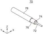
如从图1所理解的,连接器10的电缆保持部14保持电缆70的端部部分。参照图8,电缆70具有中心导体(或者信号导体)72、绝缘体74、外导体(或者接地导体)76以及外护套78。如图8所示,中心导体72的端部和外导体76的端部暴露在外。中心导体72的暴露部分和外导体76的暴露部分在横向方向上彼此间隔开。详细地,中心导体72的端部形成电缆70的端部,并且外导体76的端部与电缆70(或者中心导体72)的端部间隔开。As understood from FIG. 1 , the
参照图3和图4,连接器10设有上壳体20、信号端子30、保持构件40、电缆固定构件50、以及下壳体(或者接地构件)60。在本实施例中,信号端子30、保持构件40、电缆固定构件50以及下壳体(或者接地构件)60形成连接器主要部分。3 and 4 , the
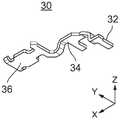
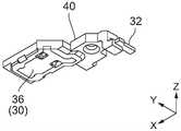
如图9和图10所示,信号端子30具有连接部32、耦合部34以及接触部36。连接部32在横向方向上具有较长形状。接触部36在前-后方向上具有较长形状。耦合部34将连接部32和接触部36耦合至彼此。连接部32、耦合部34以及接触部36按照该顺序布置在前-后方向上。连接部32是与电缆70的中心导体72(见图8)的端部连接的部件。接触部36是当连接器10与配对连接器80匹配时(见图2)与配对信号触点82(见图1)接触的部件。信号端子30是通过单一金属片加工而成。As shown in FIGS. 9 and 10 , the
如图11和图12所示,保持构件40具有与信号端子30相对应的形状。使用绝缘树脂将保持构件40与信号端子30模制为整体。因此,保持构件40保持信号端子30。在信号端子30由保持构件40保持的状态下,连接部32至少部分地暴露在外。尤其,连接部32的上表面暴露在外。在该状态下,接触部36也至少部分地暴露在外。尤其,接触部36的下表面暴露在外。在本实施例中,上-下方向是垂直于前-后方向和横向方向两者的Z方向。正Z方向指向上方,而负Z方向指向下方。上表面是面朝上方的表面,而下表面是面朝下方的表面。As shown in FIGS. 11 and 12 , the holding
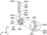
如图13至图15所示,电缆固定构件50具有夹紧部52和固定部54。然而,本发明不限于此。电缆固定构件50可以不具有固定部54。电缆固定构件50是通过单一金属片加工而成。夹紧部52弯曲为大约圆柱形形状以便夹紧电缆70。如图16所示,夹紧部52在其夹紧电缆70之前具有像展翅的形状。如从图13至图15理解的,在夹紧部52夹紧电缆70的状态下,夹紧部52的端部521彼此间隔开并且彼此相对。换言之,在夹紧电缆70的状态下,夹紧部52本身没有重叠的部分。因此,夹紧部52具有用于保持电缆70的足够的力量。As shown in FIGS. 13 to 15 , the
如图13和图14所示,夹紧部52的上部形成有在上-下方向上向下凹陷的凹陷部523。凹陷部523与突出部525(见图6和图7)相对应,突出部525位于夹紧部52的内周以便防止电缆70脱落。As shown in FIGS. 13 and 14 , the upper portion of the
如从图5至图8理解的,电缆固定构件50的夹紧部52夹紧电缆70的外导体(或者接地导体)76的暴露部分。在此,与夹紧部52的凹陷部523相对应的突出部525直接与外导体76接触。因此,即使当夹紧部52不仅夹紧外导体76的暴露部分而且部分覆盖外护套78时,夹紧部52也会牢固地夹紧电缆70的外导体76。As understood from FIGS. 5 to 8 , the
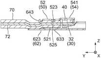
除了图13和图14之外,还参照图3,电缆固定构件50的固定部54具有上板部541和后板部543。当沿着横向方向观看固定部54时,电缆固定构件50具有L形状。Referring to FIG. 3 in addition to FIGS. 13 and 14 , the fixing
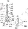
如图17至图21所示,下壳体60具有电缆接收部62和接地连接部64,接地连接部64在前-后方向上位于电缆接收部62的前方。电缆接收部62构成连接器10的电缆保持部14(见图3或者图4)的一部分。此外,接地连接部64构成连接器10的装配部12(见图3或者图4)的至少一部分。如从图1和图2理解的,在连接器10与配对连接器80匹配的状态下,接地连接部64由容纳部801接收。在该状态下,接地连接部64在上-下方向上定位在配对接地触点84的上方。另一方面,在连接器10与配对连接器80匹配的状态下,电缆接收部62定位在容纳部801的后方。As shown in FIGS. 17 to 21 , the
如图17至图21所示,接地连接部64具有主板641和沿着主板641的边缘形成的边缘部643。边缘部643在横向方向上连续地构成至主板641的两个侧边缘并且至主板641的前边缘。边缘部643从主板641向上突出。As shown in FIGS. 17 to 21 , the
如图17至图20所示,主板641形成有开口645,开口645在上-下方向上在其中心部分处穿透主板641。如从图6理解的,由保持构件40保持的信号端子30的接触部36至少部分地位于开口645中。接触部36的下表面和主板641的下表面大体上彼此齐平。相应地,当连接器10与配对连接器80匹配时,信号端子30的接触部36与配对信号触点82(见图1)接触,并且主板641与配对接地触点84(见图1)接触。因此,当连接器10与配对连接器80匹配时,接地连接部64连接至配对接地触点84。As shown in FIGS. 17 to 20 , the
如从图19理解的,电缆接收部62在与前-后方向相交的方向上具有较长形状。换言之,电缆接收部62在相交方向上延伸。在本实施例中,相交方向与横向方向相同。然而,本发明不限于此。相交方向可以针对横向方向具有倾斜。As understood from FIG. 19 , the
如图20所示,电缆接收部62从接地连接部64向下突出。电缆接收部62在上-下方向上位于主板641的下方,除了其一部分(或者后板625的一部分)之外。电缆接收部62还具有在垂直于相交方向的平面中带有在上-下方向上向上开口的形状的截面。在本实施例中,电缆接收部62的截面形状是有角的C形状。详细地,电缆接收部62具有:从接地连接部64的后边缘向下延伸的前板621、从前板621的下边缘向后方延伸的底板623以及从底板623的后边缘向上延伸的后板625。然而,本发明不限于此。例如,电缆接收部62的截面形状可以是半圆形状等。然而,就其制造的容易性而言,电缆接收部62的截面形状优选地是本实施例中的有角的C形状。As shown in FIG. 20 , the
参照图3至图7,下壳体60附接至保持构件40。如尤其从图4理解的,下壳体60在其附接至保持构件40的状态下,至少部分地覆盖保持构件40的下侧。此外,在下壳体60附接至保持构件40的状态下,由保持构件40保持的信号端子30的接触部36部分地暴露在下壳体60的开口645中。Referring to FIGS. 3 to 7 , the
如图3至图5所示,电缆固定构件50附接至电缆接收部62。详细地,电缆固定构件50的后板部543(或者固定部54)被固定至电缆接收部62的后板625。在本实施例中,后板部543位于后板625的后方并且被点焊至后板625。如图3和图4所示,多个焊接点631留在后板625上。然而,本发明不限于此。后板部543与后板625之间的固定可以是通过粘合等来进行。在电缆固定构件50不具有固定部54的情况下,夹紧部52可以被固定至电缆接收部62。As shown in FIGS. 3 to 5 , the
参照图4、图6和图7,在电缆接收部62的底板623上,留下了焊接点633。焊接点633是由通过点焊将电缆固定构件50的夹紧部52固定至电缆接收部62的底板623上造成的。即是说,在本实施例中,夹紧部52连接至电缆接收部62的底部部分并且在连接地点通过焊接被固定至电缆接收部62。因此,在本实施例中,夹紧部52在上-下方向上在位于接地连接部64的下方的地点处连接至电缆接收部62。4 , 6 and 7 , on the
如上所述,在本实施例中,电缆固定构件50附接至电缆接收部62。因此,电缆70的外导体(或者接地导体)76和下壳体(或者接地构件)60电气地连接至彼此,以在其间形成电气路径。如从图3和图7理解的,电缆70的外导体76(见图8)与下壳体60之间的电气路径在数量上为二。电气路径中的第一路径是通过夹紧部52和固定部54到达下壳体60的后板625的路径。电气路径中的第二路径是通过夹紧部52到达下壳体60的底板623的路径。第二路径明显短于第一路径。相应地,当连接器10与配对连接器80匹配时,第二路径的存在会缩短外导体76与配对接地触点84之间的电气路径。因此,与不具有第二路径的连接器相比,本实施例的连接器10可以提供良好的信号特性。尽管夹紧部52在本实施例中连接至底板623,但本发明不限于此。夹紧部52可以连接至电缆接收部62的前板621或者后板625。As described above, in the present embodiment, the
如从图3至图7理解的,通过将下壳体60附接至保持构件40并且将电缆固定构件50固定至电缆接收部62,将电缆70的端部容纳在电缆接收部62中。以这种方式,电缆70沿着相交方向从电缆接收部62延伸出去。换言之,电缆70在不同于匹配方向的方向上延伸。因此,与使电缆的铺设方向与其匹配方向相同的连接器相比,连接器10可以减小其后面剩余的死空间。As understood from FIGS. 3 to 7 , by attaching the
如从图5和图7理解的,在电缆固定构件50被固定至电缆接收部62的状态下,夹紧部52在相交方向上与接地连接部64的主板641重叠。即是说,夹紧部52在相交方向上与装配部12(见图3)重叠。换言之,当沿着前-后方向观看时,夹紧部52在横向方向上位于接地连接部64的主板641的两个端部的内部。这也可以被说成是,夹紧部52的两个端部在横向方向上定位在装配部12的两个端部的内部。然而,本发明不限于此。夹紧部52在相交方向上与装配部12重叠就足够了。此外,夹紧部52在相交方向上位于电缆接收部62的两个端部的内部就足够了。根据本实施例,由于电缆固定构件50与下壳体60不同,所以关于用于夹紧电缆70的位置的设计自由度较高。相应地,可以通过将夹紧部52布置为使得夹紧部52在相交方向上与装配部12重叠,从而减小连接器10的整体尺寸的增加。As understood from FIGS. 5 and 7 , in a state where the
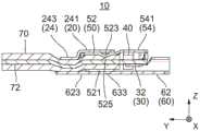
如从图1、图3、图4、图22和图23理解的,上壳体20与下壳体60进行组合。上壳体20具有前部22和后部24。前部22具有上板221和下板223。上板221和下板223延续至彼此并且大体上布置为平行于彼此。前部22部分地形成连接器10的装配部12。前部22的上板221至少部分地覆盖保持构件40的上侧。在上壳体20和下壳体60彼此组合的状态下,下板223被固定至接地连接部64的主板641。在本实施例中,使用点焊来用于该固定。相应地,如图4所示,在接地连接部64的主板641上,留下了多个焊接点635。此外,后部24部分地形成连接器10的电缆保持部14。As understood from FIGS. 1 , 3 , 4 , 22 and 23 , the
如图3和图4所示,上壳体20的后部24具有覆盖部241、电缆固定部243、以及后板部245。覆盖部241部分地覆盖夹紧部52的上侧。如从图23理解的,电缆固定部243将电缆70的由外护套78(见图8)与电缆接收部62覆盖的一部分固定。如从图1、图2和图22理解的,后板部245被固定至电缆接收部62的后板625。在本实施例中,后板部245位于后板625的后方并且通过点焊被固定至后板625。如图1和图2所示,在后板部245上,留下了多个焊接点637。As shown in FIGS. 3 and 4 , the
如从图22理解的,在本实施例的连接器10中,电缆70的中心在上-下方向上位于装配部12(见图1)的中间的下方。相应地,当连接器10和配对连接器80彼此匹配时(见图2),连接器10在对着配对连接器80突出的一部分的高度可以在上-下方向上可以减小,优选地减小至没有。因此,可以减小由连接器10和配对连接器80组成的连接器组件的高度。在本实施例中,在连接器10与配对连接器80匹配的状态下,连接器10的最顶部位置和配对连接器80的最顶部位置在上-下方向上彼此相同。As understood from FIG. 22 , in the
实施例2Example 2
如图24至图28所示,本发明的实施例2的连接器设有下壳体60A。由于连接器的其它部分与实施例1的连接器10相同,在此省略对其它部分的描述。As shown in FIGS. 24 to 28 , the connector according to the second embodiment of the present invention is provided with a
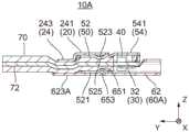
参照图24至图28,下壳体60A具有形成至电缆接收部62的底板623A的突出部651。突出部651通过使底板623A部分地突出来形成。底板623A的下表面形成有与突出部651相对应的凹陷部653。24 to 28 , the
如从图29和图30理解的,当电缆固定构件50附接至电缆接收部62时,突出部651压抵夹紧部52。在这种情况下,突出部651可以是通过力来压抵夹紧部52,该力的程度使突出部651和夹紧部52中的至少一个变形。因此,电缆70的外导体(或者接地导体)76(见图8)和下壳体(或者接地构件)60A通过夹紧部52电气地连接至彼此。因此,本实施例的连接器也可以获得良好的信号传输特性。As understood from FIGS. 29 and 30 , when the
实施例3Example 3
如图31至图34所示,本发明的实施例3的连接器设有的下壳体60B。由于连接器的其它部分与实施例1的连接器10的相同,在此省略对其它部分的描述。As shown in FIGS. 31 to 34 , the connector according to the third embodiment of the present invention is provided with a
参照图31至图34,下壳体60B具有形成至电缆接收部62的底板623B的按压部655。按压部655通过切割和弯曲底板623B加工而成。按压部655为悬臂并且可弹性地变形。31 to 34 , the
如从图35和图36理解的,当电缆固定构件50附接至电缆接收部62时,按压部655压抵夹紧部52。在这种情况下,按压部655弹性地变形并且通过其反作用力按压夹紧部52。因此,电缆70的外导体(或者接地导体)76(见图8)和下壳体(或者接地构件)60B通过夹紧部52电气地连接至彼此。因此,本实施例的连接器也可以获得良好的信号传输特性。As understood from FIGS. 35 and 36 , when the
实施例4Example 4
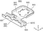
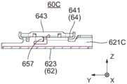
如图37至图40所示,本发明的实施例4的连接器设有下壳体60C。由于连接器的其它部分与实施例1的连接器10相同,在此省略对其它部分的描述。As shown in FIGS. 37 to 40 , the connector according to the fourth embodiment of the present invention is provided with a
参照图37至图40,下壳体60C具有形成至电缆接收部62的前板621C的按压部657。按压部657通过切割和弯曲加工下壳体60C的金属片而成。按压部657为悬臂并且可弹性地变形。37 to 40 , the
如从图41理解的,当电缆固定构件50附接至电缆接收部62时,按压部657压抵夹紧部52。在这种情况下,按压部657弹性地变形并且通过其反作用力按压夹紧部52。因此,电缆70的外导体(或者接地导体)76(见图8)和下壳体(或者接地构件)60C通过夹紧部52电气地连接至彼此。与实施例3的连接器的按压部655相比,按压部657的位置更接近主板641。相应地,从外导体76至配对接地触点(或者配对接地构件)84的路径可以更大程度地缩短。因此,可以获得更好的信号传输特性。As understood from FIG. 41 , when the
尽管通过优选实施例对本发明进行了描述,但本发明不限于这些优选实施例。例如,尽管连接器10具有上壳体20和下壳体60,但本发明可以具有单一的外壳(或者接地构件)来代替这些外壳。Although the present invention has been described in terms of preferred embodiments, the present invention is not limited to these preferred embodiments. For example, while
尽管已经描述了被认为是本发明的优选实施例,但在本领域的技术人员理解范围内,在不背离本发明的精神的情况下,可以对实施例作出其它和进一步的修改,并且所有这些实施例均落入本发明的保护范围之内。While what are considered to be preferred embodiments of the present invention have been described, other and further modifications to the embodiments may be made without departing from the spirit of the invention, and all such The embodiments all fall within the protection scope of the present invention.
Claims (9)
Applications Claiming Priority (2)
| Application Number | Priority Date | Filing Date | Title |
|---|---|---|---|
| JP2017210983AJP6959832B2 (en) | 2017-10-31 | 2017-10-31 | connector |
| JP2017-210983 | 2017-10-31 |
Publications (2)
| Publication Number | Publication Date |
|---|---|
| CN109728462A CN109728462A (en) | 2019-05-07 |
| CN109728462Btrue CN109728462B (en) | 2020-09-18 |
Family
ID=66244393
Family Applications (1)
| Application Number | Title | Priority Date | Filing Date |
|---|---|---|---|
| CN201811124887.XAActiveCN109728462B (en) | 2017-10-31 | 2018-09-26 | Connector with a locking member |
Country Status (3)
| Country | Link |
|---|---|
| US (1) | US10381786B2 (en) |
| JP (1) | JP6959832B2 (en) |
| CN (1) | CN109728462B (en) |
Families Citing this family (2)
| Publication number | Priority date | Publication date | Assignee | Title |
|---|---|---|---|---|
| JP7347978B2 (en)* | 2019-07-16 | 2023-09-20 | 日本航空電子工業株式会社 | Connection structure, manufacturing method of connection structure, and cable of connection structure |
| US11569609B2 (en)* | 2020-07-22 | 2023-01-31 | Japan Aviation Electronics Industry, Limited | Cable clamp and charging connector |
Citations (5)
| Publication number | Priority date | Publication date | Assignee | Title |
|---|---|---|---|---|
| JP2001126812A (en)* | 1999-10-22 | 2001-05-11 | Murata Mfg Co Ltd | Coaxial connector and electronic device with coaxial connector |
| CN1647323A (en)* | 2002-03-26 | 2005-07-27 | 莫莱克斯公司 | High-speed cable connector with stacking structure |
| JP2007287432A (en)* | 2006-04-14 | 2007-11-01 | Sumitomo Electric Ind Ltd | Multi-core cable with connector |
| CN101167217A (en)* | 2005-02-28 | 2008-04-23 | 莫莱克斯公司 | Fine-pitch anti-wicking terminals and connectors using same |
| CN103579794A (en)* | 2012-07-30 | 2014-02-12 | 泰科电子公司 | Coaxial cable assembly |
Family Cites Families (12)
| Publication number | Priority date | Publication date | Assignee | Title |
|---|---|---|---|---|
| JPS5925103Y2 (en)* | 1978-11-06 | 1984-07-24 | 三和電工株式会社 | L-type pin plug |
| CA2434525C (en)* | 1994-08-24 | 2006-01-03 | Canon Kabushiki Kaisha | Ink container for ink jet printer, holder for the container carriage for the holder and ink jet printer |
| JP3186021B2 (en) | 1995-02-15 | 2001-07-11 | タイコエレクトロニクスアンプ株式会社 | Connector for coaxial cable and method of manufacturing the same |
| JP2000100492A (en)* | 1998-09-25 | 2000-04-07 | Matsushita Electric Works Ltd | Television terminal |
| JP4248669B2 (en)* | 1999-04-16 | 2009-04-02 | マスプロ電工株式会社 | L-shaped coaxial plug connector |
| JP3985559B2 (en)* | 2002-03-19 | 2007-10-03 | セイコーエプソン株式会社 | Discharge device, liquid crystal display device manufacturing method, organic EL device manufacturing method, electron emission device manufacturing method, PDP device manufacturing method, electrophoretic display device manufacturing method, color filter manufacturing method, organic EL manufacturing method , Spacer forming method, metal wiring forming method, lens forming method, resist forming method, and light diffuser forming method |
| US7455528B2 (en)* | 2006-09-08 | 2008-11-25 | Siemens Energy & Automation, Inc. | Devices and/or systems for coupling a PLC bus |
| US7611358B2 (en)* | 2006-09-08 | 2009-11-03 | Siemens Energy & Automation, Inc. | Method of coupling circuit board connectors |
| JP5152221B2 (en)* | 2010-02-19 | 2013-02-27 | 第一精工株式会社 | Electrical connector and electrical connector assembly |
| JP5720148B2 (en)* | 2010-09-03 | 2015-05-20 | セイコーエプソン株式会社 | Printing material cartridge and printing material supply system |
| JP2015125963A (en) | 2013-12-27 | 2015-07-06 | 第一精工株式会社 | Coaxial connector device |
| JP2016146251A (en)* | 2015-02-06 | 2016-08-12 | 第一精工株式会社 | Electrical connector and electrical connector assembly |
- 2017
- 2017-10-31JPJP2017210983Apatent/JP6959832B2/enactiveActive
- 2018
- 2018-08-31USUS16/118,698patent/US10381786B2/enactiveActive
- 2018-09-26CNCN201811124887.XApatent/CN109728462B/enactiveActive
Patent Citations (5)
| Publication number | Priority date | Publication date | Assignee | Title |
|---|---|---|---|---|
| JP2001126812A (en)* | 1999-10-22 | 2001-05-11 | Murata Mfg Co Ltd | Coaxial connector and electronic device with coaxial connector |
| CN1647323A (en)* | 2002-03-26 | 2005-07-27 | 莫莱克斯公司 | High-speed cable connector with stacking structure |
| CN101167217A (en)* | 2005-02-28 | 2008-04-23 | 莫莱克斯公司 | Fine-pitch anti-wicking terminals and connectors using same |
| JP2007287432A (en)* | 2006-04-14 | 2007-11-01 | Sumitomo Electric Ind Ltd | Multi-core cable with connector |
| CN103579794A (en)* | 2012-07-30 | 2014-02-12 | 泰科电子公司 | Coaxial cable assembly |
Also Published As
| Publication number | Publication date |
|---|---|
| US20190131747A1 (en) | 2019-05-02 |
| JP6959832B2 (en) | 2021-11-05 |
| US10381786B2 (en) | 2019-08-13 |
| JP2019083164A (en) | 2019-05-30 |
| CN109728462A (en) | 2019-05-07 |
Similar Documents
| Publication | Publication Date | Title |
|---|---|---|
| CN109804511B (en) | connector structure | |
| KR101294607B1 (en) | Electrical connector and assembly thereof | |
| US7654856B2 (en) | Cable connector assembly having strain relief member for cable | |
| JP2017098079A (en) | Shielded connector and shielded cable with connector | |
| CN110235318A (en) | Shield terminal | |
| GB2325793A (en) | Electrical connector | |
| US12347984B2 (en) | Electrical connector | |
| JP4652742B2 (en) | connector | |
| US10177477B2 (en) | Connector and connector assembly | |
| CN106329230B (en) | electrical connector | |
| CN110021847A (en) | Shield terminal unit and connector | |
| CN109728462B (en) | Connector with a locking member | |
| KR102550876B1 (en) | Connector for coaxial cable | |
| JP2007317554A (en) | Connector and connector system | |
| KR102463691B1 (en) | Connector | |
| CN107732480B (en) | Cable assembly with improved cable retention | |
| TW202431732A (en) | Connector device | |
| KR20210009235A (en) | Joint connector for vehicle | |
| JP2019083164A5 (en) | ||
| CN102394419B (en) | Connector | |
| WO2020183847A1 (en) | Terminal, connector, and connector construct | |
| JP2021015767A (en) | Connection structure, manufacturing method of connection structure and cable of connection structure | |
| CN214478080U (en) | Electrical connector | |
| EP1575133B1 (en) | A connector with a thinner design | |
| CN201191695Y (en) | Electric connector switching device |
Legal Events
| Date | Code | Title | Description |
|---|---|---|---|
| PB01 | Publication | ||
| PB01 | Publication | ||
| SE01 | Entry into force of request for substantive examination | ||
| SE01 | Entry into force of request for substantive examination | ||
| GR01 | Patent grant | ||
| GR01 | Patent grant |