CN109716142B - Automatic analysis device - Google Patents
Automatic analysis deviceDownload PDFInfo
- Publication number
- CN109716142B CN109716142BCN201780056408.2ACN201780056408ACN109716142BCN 109716142 BCN109716142 BCN 109716142BCN 201780056408 ACN201780056408 ACN 201780056408ACN 109716142 BCN109716142 BCN 109716142B
- Authority
- CN
- China
- Prior art keywords
- nozzle
- cleaning
- reagent
- pressure
- liquid
- Prior art date
- Legal status (The legal status is an assumption and is not a legal conclusion. Google has not performed a legal analysis and makes no representation as to the accuracy of the status listed.)
- Active
Links
Images


Classifications
- G—PHYSICS
- G01—MEASURING; TESTING
- G01N—INVESTIGATING OR ANALYSING MATERIALS BY DETERMINING THEIR CHEMICAL OR PHYSICAL PROPERTIES
- G01N35/00—Automatic analysis not limited to methods or materials provided for in any single one of groups G01N1/00 - G01N33/00; Handling materials therefor
- G01N35/10—Devices for transferring samples or any liquids to, in, or from, the analysis apparatus, e.g. suction devices, injection devices
- G01N35/1004—Cleaning sample transfer devices
- G—PHYSICS
- G01—MEASURING; TESTING
- G01N—INVESTIGATING OR ANALYSING MATERIALS BY DETERMINING THEIR CHEMICAL OR PHYSICAL PROPERTIES
- G01N35/00—Automatic analysis not limited to methods or materials provided for in any single one of groups G01N1/00 - G01N33/00; Handling materials therefor
- G01N35/10—Devices for transferring samples or any liquids to, in, or from, the analysis apparatus, e.g. suction devices, injection devices
- G01N35/1009—Characterised by arrangements for controlling the aspiration or dispense of liquids
- G01N35/1016—Control of the volume dispensed or introduced
- G—PHYSICS
- G01—MEASURING; TESTING
- G01N—INVESTIGATING OR ANALYSING MATERIALS BY DETERMINING THEIR CHEMICAL OR PHYSICAL PROPERTIES
- G01N35/00—Automatic analysis not limited to methods or materials provided for in any single one of groups G01N1/00 - G01N33/00; Handling materials therefor
- G01N35/02—Automatic analysis not limited to methods or materials provided for in any single one of groups G01N1/00 - G01N33/00; Handling materials therefor using a plurality of sample containers moved by a conveyor system past one or more treatment or analysis stations
- G01N35/04—Details of the conveyor system
- G01N2035/0401—Sample carriers, cuvettes or reaction vessels
- G01N2035/0437—Cleaning cuvettes or reaction vessels
Landscapes
- Physics & Mathematics (AREA)
- Health & Medical Sciences (AREA)
- Life Sciences & Earth Sciences (AREA)
- Chemical & Material Sciences (AREA)
- Analytical Chemistry (AREA)
- Biochemistry (AREA)
- General Health & Medical Sciences (AREA)
- General Physics & Mathematics (AREA)
- Immunology (AREA)
- Pathology (AREA)
- Automatic Analysis And Handling Materials Therefor (AREA)
Abstract
Description
Translated fromChinese技术领域technical field
本发明涉及对血液、尿等含有多种成分的生物体试样中的目标成分的浓度或活性值进行测量的自动分析装置,特别涉及具备分注机构的自动分析装置,上述分注机构具备吸引试样、试剂等液体的喷嘴和对该喷嘴内进行清洗的清洗机构。The present invention relates to an automatic analysis device for measuring the concentration or activity value of a target component in a biological sample containing multiple components such as blood and urine, and in particular to an automatic analysis device equipped with a dispensing mechanism, the above-mentioned dispensing mechanism has a suction A nozzle for liquids such as samples and reagents, and a cleaning mechanism for cleaning the inside of the nozzle.
背景技术Background technique
自动分析装置是分析血液、尿、脊髓液等生物体试样的装置。自动分析装置具有如下功能:使用带有试样用、试剂用喷嘴的分注机构,将试样、试剂从各自的保存容器向反应容器内分注,且在对试样试剂的混合液进行搅拌后,利用光度计对该反应液的色调变化进行计量,根据该计量出的数据,对试样内的目标物质进行定量,并输出结果。在自动分析装置中,当试样、试剂的喷嘴反复进行上述分注动作时,为了避免试样、试剂间的交叉污染,在将目标试样、试剂吐出至反应容器后,准备接下来的分注动作而进行喷嘴内壁及外壁的清洗。The automatic analyzer is a device for analyzing biological samples such as blood, urine, and spinal fluid. The automatic analysis device has the following functions: use the dispensing mechanism with nozzles for samples and reagents to dispense samples and reagents from their respective storage containers into reaction containers, and stir the mixed solution of sample reagents Then, the change in color tone of the reaction liquid is measured by a photometer, and the target substance in the sample is quantified based on the measured data, and the result is output. In an automatic analyzer, when the nozzles of samples and reagents repeatedly perform the above dispensing operations, in order to avoid cross-contamination between samples and reagents, after the target samples and reagents are discharged into the reaction container, the next dispensing operation is prepared. Note action to clean the inner and outer walls of the nozzle.
清洗分注喷嘴的内壁的情况下,一般是从与分注喷嘴连接的配管流通清洗水,冲洗残存于分注喷嘴内的检体或试剂。另外,在清洗分注喷嘴的外壁的情况下,从配置于分注喷嘴周围的清洗喷嘴吐出清洗水,冲洗检体或试剂。通过使检体及试剂分注时的液体的移送和内壁清洗时的液体的流路为同一配管,能够容易地对喷嘴内进行清洗。When cleaning the inner wall of the dispensing nozzle, generally, washing water flows through a pipe connected to the dispensing nozzle to rinse away the sample or reagent remaining in the dispensing nozzle. In addition, when cleaning the outer wall of the dispensing nozzle, washing water is discharged from a cleaning nozzle arranged around the dispensing nozzle to rinse the sample or the reagent. The inside of the nozzle can be easily cleaned by making the transfer of the liquid during dispensing of the sample and the reagent and the flow path of the liquid during inner wall cleaning the same pipe.
分注动作时,与喷嘴外壁相比,内壁的吸引时的污染范围更大,因此,喷嘴内壁的清洗效率对交叉污染量影响较大。试样、试剂的交叉污染必须以处于临床上没有问题的范围的方式设计。近年来,就自动分析装置而言,要求低液量化,并且为了对应各种检查项目,要求处理多种多样的试样、试剂。另外,在大量地处理检体的检查中心、患者数多的医院,要求检查的迅速性、准确性。降低装置的交叉污染成为为了实现这些需求的所必须的要素。During the dispensing operation, compared with the outer wall of the nozzle, the contamination range of the inner wall during suction is larger. Therefore, the cleaning efficiency of the inner wall of the nozzle has a greater influence on the amount of cross-contamination. Cross-contamination of samples and reagents must be designed so that it falls within a clinically non-problematic range. In recent years, automatic analyzers have been required to quantify low levels of liquid, and to handle various samples and reagents in order to respond to various inspection items. In addition, in examination centers that handle a large number of specimens and in hospitals with a large number of patients, promptness and accuracy of examinations are required. Reducing cross-contamination of devices has become an essential element in order to fulfill these demands.
现有技术文献prior art literature
专利文献patent documents
专利文献1:日本特开2011-33420号公报Patent Document 1: Japanese Patent Laid-Open No. 2011-33420
发明内容Contents of the invention
发明所要解决的课题The problem to be solved by the invention
自动分析装置中,分注试样、试剂的喷嘴在各分注动作必须进行能够将交叉污染量降低至临床上没有问题的范围的程度的清洗。在自动分析装置中,若要实现高处理能力,则倾向于缩短各分注动作每一个循环的时间,随之,能够设定的清洗时间也缩短。自动分析装置为了确保分析性能,在该既定的时间内需要得到有效的清洗效果。In an automatic analyzer, nozzles for dispensing samples and reagents must be cleaned to such an extent that the amount of cross-contamination can be reduced to a clinically acceptable range during each dispensing operation. In an automatic analyzer, in order to achieve high throughput, the time per cycle of each dispensing operation tends to be shortened, and accordingly, the settable cleaning time is also shortened. In order to ensure the analytical performance of the automatic analyzer, it is necessary to obtain an effective cleaning effect within the predetermined time.
自动分析装置使用的喷嘴为管状,在其内部通过从送液泵输送的清洗液、例如,通常通过离子交换水等而进行喷嘴内部的清洗。为了提高喷嘴的内壁的清洗效果,例如,可以采用如专利文献1那样地使用清洗时专用的送液流路来提高清洗时的流速的方法等。但是,从对装置、泵的负载、耗水量的观点出发,通过送液泵送出的清洗液量有限。而且,自动分析装置使用的喷嘴为与分注机构的结构配合而绞合、弯曲、与管的接合部等喷嘴内的流路形状复杂地变化的喷嘴。在喷嘴形状变化的部分,由于产生流速的偏差,因此局部存在容易残留污垢的部位,上述流速的偏差导致清洗液流的回旋、淤水等。仅通过增加送液量使流速提高无法消除上述的流动偏差,清洗效果提高有限。为了高效地进行清洗,需要消除上述的流速偏差。The nozzle used in the automatic analysis device has a tubular shape, and the inside of the nozzle is cleaned with a cleaning liquid sent from a liquid delivery pump, for example, usually with ion-exchanged water or the like. In order to improve the cleaning effect of the inner wall of the nozzle, for example, as in Patent Document 1, a method of increasing the flow velocity during cleaning by using a liquid feeding channel dedicated for cleaning can be employed. However, from the standpoint of the load on the device and the pump, and the water consumption, the amount of cleaning liquid sent by the liquid sending pump is limited. Furthermore, the nozzle used in the automatic analysis device is a nozzle in which the shape of the flow path in the nozzle changes complicatedly, such as twisting, bending, and a junction with a tube, in accordance with the structure of the dispensing mechanism. In the portion where the shape of the nozzle changes, there is a local area where dirt is likely to remain due to the variation in the flow velocity. The above-mentioned variation in the flow velocity causes swirling of the cleaning liquid flow, stasis, and the like. The above-mentioned flow deviation cannot be eliminated only by increasing the liquid delivery volume to increase the flow rate, and the improvement of the cleaning effect is limited. In order to perform cleaning efficiently, it is necessary to eliminate the above-mentioned flow rate variation.
本发明的目的在于提供一种自动分析装置,具备能够在送液泵压有限和清洗时间有限的基础上,高效地清除喷嘴内壁的污垢的机构。The purpose of the present invention is to provide an automatic analysis device with a mechanism capable of efficiently removing the dirt on the inner wall of the nozzle on the basis of limited liquid delivery pump pressure and limited cleaning time.
用于解决课题的方案Solution to the problem
用于解决上述课题的本发明的结构如下。The structure of this invention for solving the said subject is as follows.
一种自动分析装置,其具备:试样喷嘴,其向反应容器分注试样;试剂喷嘴,其向反应容器分注试剂;反应盘,其具备对试样和试剂进行混合的反应容器;压力变化机构,其使上述试样喷嘴和上述试剂喷嘴的任一喷嘴内的压力变化;送液机构,其向上述喷嘴送入清洗液;配管,其连接上述喷嘴、上述压力变化机构以及上述送液机构;以及控制器,其控制上述压力变化机构及上述送液机构,上述控制器通过从上述送液机构向上述喷嘴送入清洗液而清洗上述喷嘴的内部,上述控制器在上述喷嘴的内部的清洗时通过控制上述压力变化机构而使从上述送液机构送入的清洗液的流速减速。An automatic analysis device, which includes: a sample nozzle, which dispenses a sample into a reaction container; a reagent nozzle, which dispenses a reagent into the reaction container; a reaction plate, which has a reaction container for mixing the sample and the reagent; a changing mechanism that changes the pressure in any one of the sample nozzle and the reagent nozzle; a liquid feeding mechanism that feeds cleaning liquid to the nozzle; a piping that connects the nozzle, the pressure changing mechanism, and the liquid feeding mechanism; mechanism; and a controller, which controls the above-mentioned pressure changing mechanism and the above-mentioned liquid sending mechanism, and the above-mentioned controller cleans the inside of the above-mentioned nozzle by sending cleaning liquid from the above-mentioned liquid sending mechanism to the above-mentioned nozzle, and the above-mentioned controller is in the inside of the above-mentioned nozzle During cleaning, the flow velocity of the cleaning liquid fed from the liquid feeding mechanism is decelerated by controlling the pressure changing mechanism.
发明效果Invention effect
根据本发明,能够不降低装置的处理性能,而且不改变清洗液的送液泵等送液机构的压力设定而提高清洗能力。According to the present invention, the cleaning capability can be improved without reducing the processing performance of the device and without changing the pressure setting of the liquid feeding mechanism such as the cleaning liquid feeding pump.
附图说明Description of drawings
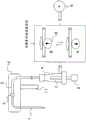
图1是试剂分注机构的概略图。Fig. 1 is a schematic diagram of a reagent dispensing mechanism.
图2是由喷嘴内清洗水的时间变化而引起的速度分布变化的概略图。Fig. 2 is a schematic diagram showing changes in velocity distribution due to time changes in washing water in the nozzle.
图3是试剂喷嘴形状及流速分布的概略图。Fig. 3 is a schematic diagram of the reagent nozzle shape and flow velocity distribution.
图4是由喷嘴特定部位的流速变化而引起的清洗水速度分布变化的概略图。Fig. 4 is a schematic diagram showing changes in velocity distribution of washing water caused by changes in flow velocity at a specific part of the nozzle.
图5是试剂分注的一连串的循环的概略图。Fig. 5 is a schematic diagram of a series of cycles of reagent dispensing.
图6是表示由本发明的注射器动作而引起的清洗水流速变化的例的图。Fig. 6 is a graph showing an example of a change in flow rate of washing water due to the operation of the syringe of the present invention.
图7是使用了开放量可调电磁阀的本发明的实施方式的概略图。Fig. 7 is a schematic diagram of an embodiment of the present invention using an adjustable opening amount solenoid valve.
图8是具备折弯机构的本发明的实施方式的概略图。Fig. 8 is a schematic diagram of an embodiment of the present invention provided with a bending mechanism.
图9是具备夹住机构的本发明的实施方式的概略图。Fig. 9 is a schematic diagram of an embodiment of the present invention provided with a clamping mechanism.
图10是自动分析装置的概略结构图。Fig. 10 is a schematic configuration diagram of an automatic analyzer.
具体实施方式Detailed ways
以下,对应用了本发明的自动分析装置进行说明。Hereinafter, an automatic analyzer to which the present invention is applied will be described.
图10是应用本发明的自动分析装置的概略结构图。图10中,在反应盘20呈圆周状排列有反应容器10。在试剂盘21内,能够在圆周上配置多个试剂瓶9。在反应盘20与试剂盘21之间设置有对载置有试样容器的架22进行移动的试样搬送机构42。而且,在反应盘20与试剂盘21之间设置有试剂分注机构23、24、25、26。另外,在反应盘20与试样搬送机构42之间设置有能够旋转、水平运动以及上下运动的试样分注机构27、28,该试样分注机构27、28具备试样分注喷嘴(简称为试样喷嘴)27a、28a。在试样喷嘴27a、28a连接有试样用泵29。试样喷嘴27a、28a进行以旋转轴为中心的旋转动作、在水平移动轨道上移动的水平动作,进行从试样容器向反应容器10的试样分注。Fig. 10 is a schematic configuration diagram of an automatic analyzer to which the present invention is applied. In FIG. 10 ,
在反应盘20的周围配置有清洗机构30、分光光度计31、搅拌机构32、33、试剂盘21、试样搬送机构42,在清洗机构30连接有清洗用泵34。在试剂分注机构23、24、25、26、试样分注机构27、28、搅拌机构32、33的动作范围内分别设置有喷嘴清洗机构(清洗槽)35、36、37、38、39、40。在试剂分注机构23、24、25、26连接有试剂用的送液泵6。A
试样容器含有血液、尿等检查试样,且载置于架22,利用试样搬送机构42搬运。另外,各机构连接于控制器41,且被控制器41进行动作控制。另外,控制器41具有作为分析反应容器10内的检查试样的分析部的功能。The sample container contains a test sample such as blood or urine, is placed on the rack 22 , and is transported by the
接下来,对分析动作进行说明。试样分注机构27用试样喷嘴27a从架22的试样容器吸引试样,且向反应容器10吐出。另外,试剂分注机构23用试剂喷嘴从试剂瓶9吸引试剂,且向反应容器10吐出。分注至同一反应容器的试样和试剂被混合,通过分光光度计对混合液进行测光。反应盘20在一个循环(例如,3.6秒)内进行旋转和停止,每当作为测量对象的反应容器通过分光光度计前方,则定期地进行测光。经过恒定时间后,基于分光光度计的测光结果,控制器41计算试样中的目标成分的浓度或活性值。于是,进行了分析。Next, the analysis operation will be described. The
接下来,对喷嘴清洗进行说明。试剂分注机构23对于使用试剂喷嘴从试剂瓶向反应容器10分注试剂在一个循环(3.6秒)内进行一次,且对此进行反复。分注后,因为可能分注不同的试剂,因此试剂喷嘴靠近清洗槽35而被清洗。也就是,试剂喷嘴依次反复进行试剂吸引、试剂吐出、喷嘴清洗、试剂吸引,将从试剂吸引到下一试剂吸引作为一个循环而驱动。另外,同样地,试样喷嘴也依次反复进行试样吸引、试样吐出、喷嘴清洗、试样吸引,将从试样吸引到下一试样吸引作为一个循环而驱动。Next, nozzle cleaning will be described. The
图1是以本发明使用的自动分析装置的分注机构的流路为中心的概略图。自动分析装置的分注机构具有试样用、试剂用,但涉及到本发明的两者的结构相似,因此,在图1中,作为分注机构的一例,表示试剂分注机构的概略。Fig. 1 is a schematic diagram centering on the flow path of the dispensing mechanism of the automatic analyzer used in the present invention. The dispensing mechanism of the automatic analyzer has a sample and a reagent, but both are similar in structure according to the present invention. Therefore, FIG. 1 shows a schematic of the reagent dispensing mechanism as an example of the dispensing mechanism.
试剂分注机构具备试剂分注用喷嘴1,试剂分注用喷嘴1穿过喷嘴臂的罩12,经由接合部3接合于管2,管2用于将流路引回至装置内。管2构成如下流路:从喷嘴接合方向经由注射器4、电磁阀5连接至作为送液机构的送液泵6。注射器的柱塞7由所连接的马达8驱动。分注机构分注目标试剂时,将电磁阀5维持关闭的状态,机构向试剂设置部移动,然后,在确认了试剂分注用喷嘴1到达试剂瓶9内试剂液面后,使柱塞7向吸引方向动作,将试剂吸入试剂分注用喷嘴1内部,之后,移动至预定的吐出位置,例如反应容器10,然后使柱塞7向吐出方向移动而将试剂吐出。吐出完成后,分注机构将试剂分注用喷嘴1移动至喷嘴清洗机构11的位置,进行清洗动作。清洗动作如下进行:通过打开电磁阀5,使送液泵的压力传递,清洗水在流路流动,且从试剂分注用喷嘴前端排出。The reagent dispensing mechanism includes a reagent dispensing nozzle 1 which passes through the
在此,送液泵6具备向试剂分注用喷嘴1送入清洗水的功能,是从配置于送液泵6的上游的清洗水箱送入清洗水的送液机构。另外,具备柱塞7的注射器4是使喷嘴内的压力变化的压力变化机构。另外,管2是连接试剂分注用喷嘴1、注射器4以及送液泵6的配管。此外,控制器41能够控制电磁阀5、送液泵6、柱塞的马达8等。此外,以下对于柱塞的控制,有时简称为注射器的控制,注射器的控制是指柱塞7的马达8的控制。Here, the
图2示意性表示清洗动作中的喷嘴壁面13内部的平均流速分布的时间变化。将电磁阀未打开时不具有流速v的状态设为图2的A。刚打开电磁阀,利用送液泵的压力开始送液时(t=0),在喷嘴13内部流动的清洗水在移动方向上以恒定速度开始流动(图2的B)。从上述状态起,逐渐地,受与内壁的摩擦等的影响,越靠近壁面的位置,速度越低,越靠近中心,速度越快(图2中C)。随着时间的经过,上述的倾向进一步变大,在流动充分发展后,平均流速分布的形状固定(图2中D)。FIG. 2 schematically shows temporal changes in the average flow velocity distribution inside the
一般地,流速越快,则清洗效果越高,因此,就整个喷嘴13的每单位时间的平均的清洗力而言,图2的D的状态最高。但是,若局部地观察喷嘴13壁面附近,则图2的D在喷嘴13内壁附近大范围地存在流速降低的区域,与之相对,图2的B状态、图2的C状态比较能够确保壁面附近的流速。图2的B状态、图2的C状态因为壁面附近的流速的速度梯度大,所以削落附着于壁面的污垢的力强,能够有效地剥去附着污垢。另外,在恒定速度的恒流下,壁面附近流速慢,因此排出至流路外之前耗费时间,通过赋予速度变动,过渡性地提高壁面附近的流速,从而能够将壁面附近的液体中含有的污垢成分短时间排出至流路外。即,对于喷嘴清洗,重要的不只是用高速的流水进行清洗,还包括具有图2的B状态、图2的C状态那样的对管壁的清洗高效的成分。Generally, the faster the flow rate, the higher the cleaning effect. Therefore, the state D in FIG. 2 is the highest in terms of the average cleaning power per unit time of the
图3中A表示自动分析装置的喷嘴形状的一例。自动分析装置必须确保分注量设定的宽度,因此,多在喷嘴前端设有颈缩部14。通过设置颈缩部14,能够确保分注时的吐出精度,并且确保吸引时的喷嘴容积。另外,设有用于将喷嘴收纳于机构内的弯曲部15、与用于将流路向装置内引回的管接合的接合部16等。图3中A对喷嘴形状仅示出了一例,除了颈缩部、弯曲、接合部以外,有时还包含扭曲等多种形状变化,本发明对于那样的形状也有效。A in FIG. 3 shows an example of a nozzle shape of an automatic analyzer. The automatic analysis device must ensure the width of the dispensing amount setting, therefore, the
一般而言,流速越快,清洗效果越提高,但是,在具有颈缩部14的部位,如图3中B所示,产生因缩流而引起的回旋流。另外,如图3中C所示,流动沿颈缩部行进,因此,在流速快的情况下,在直径细的部位,流动相互碰撞,有时产生淤水。另外,如图3中D所示,在弯曲部,流动的向量急剧地变化,因此,由于离心力等的影响,在弯曲外侧清洗效果高,与之相对,在内侧清洗效果相对降低。Generally speaking, the faster the flow rate, the better the cleaning effect. However, at the portion having the constricted
图3中E表示喷嘴和管接合部的剖面的一例。喷嘴和管通过树脂等的连接部件接合,但是,在各个部件直径不同的情况下,或者由于部件公差,在各部件之间产生流路形状的变化。该情况下,产生更复杂的回旋流、淤水。E in FIG. 3 shows an example of the cross section of the nozzle and the tube junction. The nozzle and the tube are joined by a connecting member such as resin, however, if the diameters of the respective members are different or due to component tolerances, the shape of the flow path varies between the respective members. In this case, more complicated swirling flow and stagnant water are generated.
由于上述图3中B、C、D、E的回旋流、淤水,喷嘴内部的污垢不能被顺利地排出,从而成为产生交叉污染的原因之一。Due to the swirling flow and silt water in B, C, D, and E in Fig. 3 above, the dirt inside the nozzle cannot be discharged smoothly, which becomes one of the reasons for cross-contamination.
本发明提供利用了上述图2所示的喷嘴内清洗水的因时间变迁而引起的流速分布的变化的清洗效率的提高、对图3那样地喷嘴形状变化的部位的有效的清洗方法。The present invention provides an effective cleaning method for improving the cleaning efficiency by utilizing the change in the flow velocity distribution of the cleaning water in the nozzle shown in FIG. 2 as shown in FIG. 3 .
清洗时间内,通过具有多次如下时刻,即,形成图2中D所示的整个喷嘴的清洗力高的状态,并且向如上述地特殊化成壁面附近的清洗效率的图2中的B、C的状态变迁,且再次向图2中的D的状态转变,从而能够确保喷嘴壁面的平均流速,能够瞬间提高对附着于壁面附近的污垢的清洗力。During the cleaning time, by having multiple times, the cleaning power of the entire nozzle shown in D shown in FIG. 2 is high, and as described above, B and C in FIG. The state transitions to the state of D in Fig. 2 again, so that the average flow velocity of the nozzle wall can be ensured, and the cleaning power of the dirt attached to the vicinity of the wall can be instantly improved.
为了使流速分布从图2中D状态向图2中B、C状态变迁,需要降低流速。另一方面,若降低流速的时间过长,则流量降低,无法充分得到整个清洗时间内的清洗效果,因此,优选向图2中B、C状态的变迁为极短的时间。即,为了高效地清洗喷嘴内壁,有效的是,不仅进行恒定速度的清洗,还进行瞬间的流速的减速。In order to change the flow velocity distribution from state D in Fig. 2 to states B and C in Fig. 2, the flow velocity needs to be reduced. On the other hand, if the time for reducing the flow velocity is too long, the flow rate will decrease, and the cleaning effect cannot be fully obtained throughout the cleaning time. Therefore, it is preferable to make the transition to states B and C in FIG. 2 extremely short. That is, in order to efficiently clean the inner wall of the nozzle, it is effective not only to perform constant-speed cleaning but also to perform instantaneous deceleration of the flow velocity.
对于如图3所示地喷嘴形状变化而流动的形状改变的部位,上述的流速变化是有效的。在打开电磁阀,仅通过送液泵的压力将清洗水推出的情况下,若经过恒定时间,则喷嘴内的流速大致成为恒定速度。在流速为恒定速度的情况下,成为如图3中B、C、D、E所示地在特定的部位产生回旋流、淤水的状态,且稳定。由于该淤水、回旋流,有可能会残留污垢,为了消除该流动,打乱以恒定速度流动的喷嘴内的速度分布是有效的。即,使喷嘴内的流速进行加减速是有效的。The change in the flow velocity described above is effective for the portion where the shape of the flow changes due to the change in the shape of the nozzle as shown in FIG. 3 . When the solenoid valve is opened and the washing water is pushed out only by the pressure of the liquid delivery pump, the flow velocity in the nozzle becomes substantially constant after a constant time elapses. When the flow velocity is constant, swirling flow and stagnant water are generated at specific locations as shown in B, C, D, and E in FIG. 3 , and are stable. Stains may remain due to the stagnant water and swirl flow, and in order to eliminate this flow, it is effective to disturb the velocity distribution in the nozzle that flows at a constant velocity. That is, it is effective to accelerate and decelerate the flow velocity in the nozzle.
图4表示在图3的部位中流速发生了变化的情况的图像。通过流速变化,从而局部产生的回旋流、淤水的程度、位置发生变化,因此能够将因回旋流、淤水而被疏远进而未清洗的部分的壁面暴露于剪切流,而进行清洗。另外,能够将滞留于回旋流、淤水的污垢成分随着主流冲走,能够对图3的各部位得到清洗效果。FIG. 4 shows an image in which the flow velocity has changed in the portion shown in FIG. 3 . By changing the flow velocity, the degree and position of locally generated swirl flow and silt water change, so that the wall surface of the unwashed part separated by swirl flow and silt water can be exposed to shear flow and cleaned. In addition, the dirt components remaining in the swirling flow and stagnant water can be washed away with the main flow, and the cleaning effect can be obtained for each part in FIG. 3 .
以下,对于在清洗时间内提高对上述的喷嘴壁面的清洗效果、提高喷嘴的颈缩部、弯曲、连接部等的清洗力,记载通过喷嘴内清洗水的流速变化实现提高对特定部位的清洗力的效果的方法的一例。本例中,作为流速控制机构,使用分注时的吸引吐出用的注射器,但是通过电磁阀的开放时间、开放量的控制、在流路内配置颈缩部且具备使该颈缩部的程度可变的驱动器的方法、具备将流路本身折弯的机构、夹住机构等,也能够使流路内的流速变化,因此,能够得到与使用注射器的情况相同的效果。In the following, for improving the cleaning effect on the above-mentioned nozzle wall surface within the cleaning time, and improving the cleaning power of the necked part, bend, connection part, etc. of the nozzle, it is described that the cleaning power of specific parts can be improved by changing the flow velocity of the cleaning water in the nozzle. An example of the method of the effect. In this example, as the flow rate control mechanism, a syringe for suction and discharge during dispensing is used, but by controlling the opening time and opening amount of the solenoid valve, a constricted part is arranged in the flow path and the degree of the constricted part is provided. The variable actuator method, the mechanism for bending the flow path itself, the clamping mechanism, etc. can also change the flow velocity in the flow path, so that the same effect as the case of using a syringe can be obtained.
图5表示本实施例的试剂分注动作时的一连串的流程。关于试样分注,只是喷嘴径、马达、注射器分辨率不同,基本的动作的概念相同。分注循环是装置固有的性能,在任意的循环的装置中,本发明都能够应用。本发明中,以试剂探针的分注循环为3.6秒的自动分析装置为例来说明。试剂喷嘴的形状为图3所示那样的形状,在前端部分具有颈缩部,在机构内部具有弯曲、连接部。从颈缩部到前端的径例如为直径0.8mm,从颈缩部向泵方向为1.1mm。从喷嘴的前端到弯曲部的长度为160mm,弯曲部为R15mm且向大致直角方向弯曲。试剂喷嘴的循环内的最大可吸引量设为200μL。FIG. 5 shows a series of flows during the reagent dispensing operation of this embodiment. Regarding sample dispensing, only the nozzle diameter, motor, and syringe resolution are different, but the concept of the basic operation is the same. The dispensing cycle is an intrinsic property of the device, and the present invention can be applied to any cycle device. In the present invention, an automatic analyzer whose dispensing cycle of the reagent probe is 3.6 seconds is taken as an example for description. The shape of the reagent nozzle is as shown in FIG. 3 , and has a constricted portion at the front end, and has a bending and connecting portion inside the mechanism. The diameter from the constriction to the tip is, for example, 0.8 mm in diameter, and 1.1 mm from the constriction toward the pump. The length from the tip of the nozzle to the curved portion is 160mm, and the curved portion is R15mm and curved in an approximately right-angled direction. The maximum aspirable volume in the circulation of the reagent nozzle was set to 200 μL.
对于例如装置吸引150μL的试剂的情况的动作,说明本发明的应用例。分注循环中,清洗时间依赖于整个循环的时序安排,一般,整体时间的20%以上为清洗时间。若循环为3.6秒,则清洗时间为0.72秒以上。例如,清洗使用的时间设为0.9秒。若使用图5说明喷嘴的分注动作的例,则按照如下的流程进行分注动作。首先,进行吸引试剂时,为了防止试剂的淡化,进行5μL空气吸引动作(图5中A)。然后,喷嘴下降至吸引位置,通过注射器进行吸引动作。此时,在吐出用的150μL的基础上,为了防止喷嘴内部的淡化,进行多出20μL的试剂吸引(图5中B)。该动作之后,作为间隙除去动作,例如,进入吐出5μL的吐出动作。然后,喷嘴移动至试剂吐出位置,将注射器上推150μL的量,进行试剂吐出(图5中C)。在吐出动作后的喷嘴内部,残留有吸引时多吸入的试剂量减去间隙除去动作后的15μL的试剂。An example of application of the present invention will be described with regard to the operation in the case where the device sucks 150 μL of reagent, for example. In the dispensing cycle, the cleaning time depends on the timing arrangement of the entire cycle. Generally, more than 20% of the overall time is the cleaning time. If the cycle is 3.6 seconds, the cleaning time is 0.72 seconds or more. For example, the time used for cleaning is set to 0.9 seconds. When an example of the dispensing operation of the nozzle is described using FIG. 5 , the dispensing operation is performed in the following flow. First, when aspirating the reagent, in order to prevent dilution of the reagent, 5 μL of air is aspirated (A in FIG. 5 ). Then, the nozzle is lowered to the suction position, and the suction action is performed by the syringe. At this time, in addition to the 150 μL for discharge, 20 μL of reagent was aspirated in order to prevent desalination inside the nozzle (B in FIG. 5 ). After this operation, as a gap removal operation, for example, a discharge operation of discharging 5 μL is performed. Then, the nozzle moved to the reagent discharge position, and the syringe was pushed up by 150 μL to discharge the reagent (C in FIG. 5 ). In the nozzle after the discharge operation, 15 μL of the reagent after the gap removal operation was subtracted from the amount of the reagent sucked more during suction remained.
然后,在喷嘴移动至清洗位置后,打开电磁阀,进行清洗水的吐出(图5中D)。然后,在此经过0.02秒后,在电磁阀打开中使注射器向吸引方向动作,使清洗水的流速向减速方向变化(图5中E)。为了不吸入喷嘴内的试剂,而且在流速发展稳定后进行吸引动作是有效的,因此,在实施图5中E的吸引动作前,必须在电磁阀打开后设置等待时间。该等待时间根据送液泵的压力、从送液泵到喷嘴前端的流路的长度设定。或者,也可以使用压力传感器等,利用装置判断喷嘴内压力成为恒定的系统。除了流路特别长的情况,若流路长度为5m左右,则只要在约300KPa的送液泵压下具有0.02~0.1秒左右的等待时间便已足够。Then, after the nozzle moves to the washing position, the solenoid valve is opened to discharge washing water (D in FIG. 5 ). Then, 0.02 seconds later, the syringe is operated in the suction direction while the solenoid valve is open, and the flow velocity of the washing water is changed in the deceleration direction (E in FIG. 5 ). In order not to inhale the reagent in the nozzle, and it is effective to carry out the suction action after the flow rate has stabilized, therefore, before implementing the suction action E in Figure 5, a waiting time must be set after the solenoid valve is opened. The waiting time is set according to the pressure of the liquid-feeding pump and the length of the flow path from the liquid-feeding pump to the tip of the nozzle. Alternatively, a pressure sensor or the like may be used, and a device may be used to determine that the pressure in the nozzle is constant. Except for the case where the flow path is extremely long, if the flow path length is about 5 m, it is sufficient to have a waiting time of about 0.02 to 0.1 second under the liquid delivery pump pressure of about 300 KPa.
在图5中E中,电磁阀为打开的状态,向喷嘴前端方向施加有压力,因此,注射器吸引动作需要与该压力相反,以使流速变化的程度的动作量和时间进行。具体而言,通过以整体清洗时间的30%以内的时间,吸引装置吸引量上限值的30%以上的注射器动作,效果显著。即,降低流速的时间优选为整体清洗时间的30%以内。而且,优选吸引动作量尽可能地大。就本例而言,若整个清洗使用的时间为0.9秒,则进行以0.3秒以内的时间吸引最大吸引可能量200μL的30%即60μL以上的注射器动作。例如,作为满足上述条件的动作,在3.6秒循环中,在将清洗时间设定为0.9秒的情况下,在此之中,以0.2秒进行70μL量的注射器吸引动作。In E in FIG. 5 , the solenoid valve is in an open state, and pressure is applied toward the tip of the nozzle. Therefore, the suction operation of the syringe needs to be performed in the amount and time required to change the flow rate against the pressure. Specifically, the effect is remarkable by operating the syringe with 30% or more of the upper limit of the suction amount of the suction device within 30% of the total cleaning time. That is, the time for reducing the flow rate is preferably within 30% of the total cleaning time. Furthermore, it is preferable that the suction operation amount is as large as possible. In this example, if the total cleaning time is 0.9 seconds, the syringe operates to suck 30% of the maximum possible suction volume of 200 μL, that is, 60 μL or more within 0.3 seconds. For example, as an operation satisfying the above-mentioned conditions, in a 3.6-second cycle, when the cleaning time is set to 0.9 seconds, a syringe suction operation of 70 μL is performed in 0.2 seconds.
通过该吸引动作,能够使流速瞬间减速,得到上述的图2所示那样的清洗效果提高的机理,而且,通过流速变化,对于图3中B、C、D、E那样的流动偏差,可以得到清洗效果。Through this suction action, the flow velocity can be decelerated instantaneously, and the mechanism of improving the cleaning effect as shown in Figure 2 above can be obtained. Moreover, by changing the flow velocity, flow deviations such as B, C, D, and E in Figure 3 can be obtained. cleaning effect.
上述是在试剂喷嘴中的条件,若言及试样喷嘴,则由于喷嘴的直径比试剂喷嘴小,因此,以与试剂分注机构相同的时间条件,将注射器吸引量设为15%以上,也可以得到效果。上述的注射器吸引动作后,进行吐出动作(图5中F)。通常,该吐出动作是为了下一分注动作而将注射器复位于起始位置的动作,但该动作在图5中E的吸引动作之后高速且配合上述的注射器吸引量将注射器推回起始位置,由此,能够使在吸引动作下降低的流速急剧加速,能够瞬间提高清洗效果。上述动作优选在整体清洗时间的40%以下的时间将注射器返回起始位置。例如,在0.9秒的清洗时间内,使用作为40%的0.36秒以下的0.3秒进行上述动作。此外,在起始位置为柱塞被完全推压的状态,在试剂吐出的状态下,柱塞不是完全推压的状态,相距起始位置的距离残留一定程度。在使清洗水的流速减速之后的清洗水的加速工序中,以弥补该距离的方式将柱塞推压比拉回量大的距离(比与拉回量相当的体积大的体积),从而通过加速的效果提高清洗效果,并且能够通过清洗动作的一连串的流程将注射器返回起始位置。The above are the conditions in the reagent nozzle, but when it comes to the sample nozzle, since the diameter of the nozzle is smaller than that of the reagent nozzle, it is also possible to set the suction volume of the syringe to 15% or more under the same time conditions as the reagent dispensing mechanism. get the effect. After the syringe suction operation described above, the ejection operation is performed (F in FIG. 5 ). Usually, this ejecting action is an action of returning the syringe to the initial position for the next dispensing action, but this action pushes the syringe back to the initial position at a high speed after the suction action of E in Figure 5 and in accordance with the above-mentioned syringe suction volume , thereby, the flow velocity reduced by the suction operation can be rapidly accelerated, and the cleaning effect can be instantly improved. The above action preferably returns the syringe to the starting position for less than 40% of the overall wash time. For example, within the cleaning time of 0.9 seconds, the above operation is performed using 0.3 seconds which is 40% of 0.36 seconds or less. In addition, the plunger is fully pushed in the initial position, but the plunger is not fully depressed in the state where the reagent is discharged, and a certain distance remains from the initial position. In the step of accelerating the washing water after the flow velocity of the washing water is decelerated, the plunger is pushed by a distance (a volume larger than the volume corresponding to the pulled back amount) to compensate for this distance, thereby passing The effect of acceleration increases the cleaning effect and enables the syringe to be returned to the starting position through the sequence of cleaning actions.
就上述的注射器吸引、吐出动作中的流速变化而言,若在清洗时间0.9秒间从喷嘴前端吐出的清洗水量为3000μL/sec,则喷嘴内的清洗水的流速为图6所示的关系。这里的流速是注射器吸引、吐出动作时间的平均的流速。若言及图5中F的注射器吐出动作,则虽然将吐出量设为90μL,但在相同时间内越尽可能大幅地使注射器动作,则流速变化越大。作为确保图5中F的动作量的方法,在图5中C的试剂吐出后,进行空气吸引,能够将该吸引量加到图5中F的吐出动作中。另外,图5中F的动作后,再次吸引注射器,转到下一分注动作,从而能够对图5中F的动作量追加上次清洗后的注射器吸引量,进而能够使流速变化更大。With regard to the above-mentioned change in flow velocity during the suction and discharge operations of the syringe, if the amount of cleaning water discharged from the tip of the nozzle during the cleaning time of 0.9 seconds is 3000 μL/sec, the flow velocity of the cleaning water in the nozzle has the relationship shown in FIG. 6 . The flow rate here is the average flow rate of the suction and discharge operation time of the syringe. Regarding the ejection operation of the syringe in F in FIG. 5 , although the ejection volume is set to 90 μL, the greater the operation of the syringe within the same time period, the greater the change in the flow rate. As a method of ensuring the operation amount of F in FIG. 5 , air suction is performed after the reagent of C in FIG. 5 is discharged, and this suction amount can be added to the discharge operation of F in FIG. 5 . In addition, after the action of F in FIG. 5, the syringe is sucked again, and then the next dispensing action can be performed, so that the action amount of F in FIG. 5 can be added to the action amount of F in FIG.
图6是计算注射器以图5的条件清洗时的各注射器动作中的平均流速值得出的值。根据本实施例,在将注射器不动作作为标准的情况下,只要是注射器吸引时流速变动率为-12%、注射器吐出时流速变动率为+10%的流速变化,就可得到清洗效果。因此,优选以各个流速变动率的绝对值的和为20%以上的方式控制注射器。在应用了本条件的情况下,比未应用本发明的情况降低约50%左右交叉污染量。FIG. 6 is a value obtained by calculating an average flow velocity value in each syringe operation when the syringe is cleaned under the conditions shown in FIG. 5 . According to the present embodiment, when the syringe does not operate as a standard, the cleaning effect can be obtained as long as the flow velocity variation is -12% when the syringe is suctioned and +10% when the syringe is discharged. Therefore, it is preferable to control the injector so that the sum of the absolute values of the respective flow rate fluctuation rates is 20% or more. In the case of applying this condition, the amount of cross-contamination is reduced by about 50% compared with the case of not applying the present invention.
本实施例将注射器用作了流速控制机构,但是,也可以通过如图7所示地将开放量可调电磁阀16用作压力变化机构的方法、将图8所示的流路管的折弯机构17、图9所示的管的夹住机构18设为压力变化机构的方法、或者根据图1的结构使电磁阀5在清洗时瞬间地开闭来使流量变化的方法等,从而实现图5、图6的流速变化的时刻、流速变化量。In this embodiment, the syringe is used as the flow rate control mechanism, but it is also possible to use the opening amount
例如,图8的折弯机构17在清洗开始时设为图8中A状态,通过折弯机构17的工作,以图8中B状态那样将流路折弯,产生阻力,从而使喷嘴侧的流速瞬间降低。在图8中B状态下,在折弯部产生回旋流、淤水,但污垢不会到达该部位,因此不会对清洗产生问题。For example, the
若言及图9,则夹住机构18在清洗开始时为图9中A状态,通过设为图9中B状态,用夹住部压瘪管,从而使流速瞬间降低。图9的机构中,与图8同样地在该工作部产生回旋流、淤水,但污垢不会到达该部位,因此不会对清洗产生问题。Referring to FIG. 9, the
本发明能够保持现有的送液泵压,不阻碍分注循环,而且提高清洗效果,因此,尤其对高处理能力的自动分析装置有效。The present invention can maintain the existing liquid delivery pump pressure, does not hinder the dispensing cycle, and improves the cleaning effect, so it is especially effective for automatic analysis devices with high processing capacity.
以上,对实施例进行了说明。之前说明的例中,具体地说明了优选的例,但是控制器41至少在喷嘴的内部的清洗时通过控制注射器等压力变化机构使从送液泵送入的清洗水的流速减速,从而能够得到本发明的效果。The embodiments have been described above. In the example described above, a preferred example was specifically described, but the
另外,还优选的是,压力变化机构为注射器,控制器优选通过进行拉回注射器的柱塞的控制使从送液泵送入的清洗水的流速减速。这是因为,能够使用目前具备的注射器,不设置新的机构便能得到本发明的效果。In addition, it is also preferable that the pressure changing mechanism is a syringe, and the controller preferably decelerates the flow rate of the washing water fed in from the liquid delivery pump by controlling the plunger of the syringe to be pulled back. This is because the effect of the present invention can be obtained without providing a new mechanism by using a currently available syringe.
另外,优选喷嘴的内部的清洗是在分析中的一个循环内进行的清洗。这是因为该清洗是适用于短时间内的清洗的清洗方法,且无需为了清洗而降低装置的处理能力。但是,在需要短时间内有效的清洗的情况下,也能够应用于分析以外的维护清洗等的时机。In addition, it is preferable to clean the inside of the nozzle within one cycle of the analysis. This is because this cleaning is a cleaning method suitable for cleaning in a short time, and it is not necessary to reduce the processing capacity of the apparatus for cleaning. However, when efficient cleaning is required in a short period of time, it can also be applied to timings such as maintenance cleaning other than analysis.
另外,优选控制器41在从来自送液泵的清洗水的开始送入到结束的30%以下的时间使清洗水的流速减速。这是因为,能够抑制因由减速而引起的清洗水量的降低而产生的清洗效果的降低,并且对局部易于残余污垢的部分、壁面得到高的清洗效果。例如,清洗水的送入的开始能够以电磁阀的开为基准,结束以电磁阀的关为基准。In addition, it is preferable that the
另外,优选的是,控制器41以将使清洗水的流速减速的期间的平均流速比未驱动压力变化机构的状态降低10%以上的方式控制压力变化机构。这是因为,通过将降低量设为10%以上,能够将滞留于临时产生的回旋流、淤水的污垢有效地排出至外部,清洗效果提高。In addition, it is preferable that the
另外,优选的是,控制器41在通过压力变化机构使清洗水的流速减速后,通过压力变化机构使流速加速,且以与未驱动压力变化机构的状态相比,通过压力变化机构减速及加速的期间的平均流速的变动率的绝对值的和为20%以上的方式,控制器41控制压力变化机构。这是因为,变动率的振幅越大,清洗效果越提高。In addition, it is preferable that the
另外,优选的是,压力变化机构为注射器,控制器41进行如下控制:与能够吸引喷嘴能够吸引液体的量的上限的15%以上的体积相应地拉回柱塞。这是因为,在短时间的期间柱塞的拉回的体积越大,减速效果越大,越有助于清洗效果提高。In addition, it is preferable that the pressure changing mechanism is a syringe, and the
另外,优选的是,控制器41通过将柱塞推压比拉回的体积大的体积使清洗水的流速加速。除了能够通过流速的加速效果提高清洗效果外,还能够通过清洗动作的一连串的流程将注射器返回起始位置。In addition, it is preferable that the
另外,也能够是,压力变化机构是可以调整从送液泵到喷嘴的开放量的开放量可调电磁阀,控制器41通过调整开放量使从送液泵送入的清洗水的流速减速。该情况下,能够不变更现有的注射器动作而使本次的清洗水的流速减速。另外,通过将现有的电磁阀置换成开放量可调阀这样的简单的方法,可以得到高的清洗效果。In addition, the pressure changing mechanism may be an adjustable opening amount solenoid valve that can adjust the opening amount from the liquid delivery pump to the nozzle, and the
另外,也能够是,压力变化机构是将从送液泵到喷嘴的流路折弯的机构,控制器41通过折弯流路来使从送液泵送入的清洗水的流速减速。通过如图8所示地折弯,能够提高或降低流路阻力,能够进行流速的减速。Alternatively, the pressure varying mechanism may bend the flow path from the liquid-feeding pump to the nozzle, and the
另外,也能够是,压力变化机构是夹住从送液泵到喷嘴的流路的机构,控制器41通过夹住流路来使从送液泵送入的清洗水的流速降低。通过如图9所示地夹住,能够提高或降低流路阻力,能够进行流速的减速。In addition, the pressure changing mechanism may be a mechanism that sandwiches the flow path from the liquid-feeding pump to the nozzle, and the
此外,虽然示出了各种条件,在此之前示出的条件能够适当组合。另外,作为清洗液,以清洗水为例进行了说明,但使用洗涤剂等的清洗液也可得到同样的效果。In addition, although various conditions were shown, the conditions shown heretofore can be combined suitably. In addition, as the washing liquid, the washing water has been described as an example, but the same effect can be obtained by using a washing liquid such as a detergent.
符号说明Symbol Description
1—试剂分注用喷嘴,2—管,3—连接部,4—注射器,5—电磁阀,6—送液泵,7—柱塞,8—马达,9—试剂瓶,10—反应容器,11—喷嘴清洗机构,12—罩,13—喷嘴壁面,14—颈缩部,15—弯曲部,16—连接部,17—折弯机构,18—夹住机构,19—开放量可调电磁阀。1—Nozzle for reagent dispensing, 2—Tube, 3—Connecting part, 4—Syringe, 5—Solenoid valve, 6—Liquid delivery pump, 7—Plunger, 8—Motor, 9—Reagent bottle, 10—Reaction container , 11—nozzle cleaning mechanism, 12—cover, 13—nozzle wall, 14—neck constriction, 15—bending portion, 16—connecting portion, 17—bending mechanism, 18—clamping mechanism, 19—adjustable opening The electromagnetic valve.
Claims (4)
Translated fromChineseApplications Claiming Priority (3)
| Application Number | Priority Date | Filing Date | Title |
|---|---|---|---|
| JP2016183625 | 2016-09-21 | ||
| JP2016-183625 | 2016-09-21 | ||
| PCT/JP2017/028358WO2018055928A1 (en) | 2016-09-21 | 2017-08-04 | Automated analysis device |
Publications (2)
| Publication Number | Publication Date |
|---|---|
| CN109716142A CN109716142A (en) | 2019-05-03 |
| CN109716142Btrue CN109716142B (en) | 2023-06-27 |
Family
ID=61690816
Family Applications (1)
| Application Number | Title | Priority Date | Filing Date |
|---|---|---|---|
| CN201780056408.2AActiveCN109716142B (en) | 2016-09-21 | 2017-08-04 | Automatic analysis device |
Country Status (5)
| Country | Link |
|---|---|
| US (1) | US11360112B2 (en) |
| EP (1) | EP3517973B1 (en) |
| JP (1) | JP6858195B2 (en) |
| CN (1) | CN109716142B (en) |
| WO (1) | WO2018055928A1 (en) |
Families Citing this family (7)
| Publication number | Priority date | Publication date | Assignee | Title |
|---|---|---|---|---|
| JP6876650B2 (en)* | 2018-03-30 | 2021-05-26 | 日本電子株式会社 | Automatic analyzer and automatic analysis method |
| EP4047373A4 (en)* | 2019-10-18 | 2023-11-22 | Hitachi High-Tech Corporation | AUTOMATED ANALYZER |
| JP7474790B2 (en)* | 2020-02-07 | 2024-04-25 | 株式会社日立ハイテク | Automatic analysis system, control device and cleaning method |
| JP7470970B2 (en)* | 2020-04-28 | 2024-04-19 | マッスル株式会社 | Pipetting and Analytical Equipment |
| JP7394710B2 (en)* | 2020-06-23 | 2023-12-08 | 株式会社日立ハイテク | Method for cleaning the dispensing probe included in an automatic analyzer, automatic analyzer |
| US20230366901A1 (en)* | 2020-09-15 | 2023-11-16 | Hitachi High-Tech Corporation | Automatic Analysis Device |
| WO2025084179A1 (en)* | 2023-10-16 | 2025-04-24 | ソニーグループ株式会社 | Biological sample analysis device, sample nozzle cleaning method, and biological sample analysis method |
Citations (8)
| Publication number | Priority date | Publication date | Assignee | Title |
|---|---|---|---|---|
| GB2068115A (en)* | 1980-01-28 | 1981-08-05 | Coulter Electronics | Transferring fluid |
| JPH1096735A (en)* | 1996-09-25 | 1998-04-14 | Aloka Co Ltd | Aerial discharge type dispensing device |
| JPH10104240A (en)* | 1996-09-30 | 1998-04-24 | Shimadzu Corp | Probe cleaning mechanism of automatic biochemical analyzer |
| JP2003294773A (en)* | 2002-04-04 | 2003-10-15 | A & T Corp | Clinical examination automatic analyzer, cleaning method for clinical examination automatic analyzer |
| CN101869894A (en)* | 2009-04-24 | 2010-10-27 | 深圳迈瑞生物医疗电子股份有限公司 | Cleaning device, cleaning system, cleaning method and particle analyzer |
| CN102112882A (en)* | 2008-08-07 | 2011-06-29 | 株式会社日立高新技术 | Automatic analyzing device |
| JP2011163909A (en)* | 2010-02-09 | 2011-08-25 | Beckman Coulter Inc | Automatic analyzer and washing method for dispensing means |
| CN202591183U (en)* | 2012-05-10 | 2012-12-12 | 北京普析通用仪器有限责任公司 | Gas replacement type automatic liquid supplement and washing system for washing sampling probe |
Family Cites Families (7)
| Publication number | Priority date | Publication date | Assignee | Title |
|---|---|---|---|---|
| US4276260A (en)* | 1980-01-28 | 1981-06-30 | Coulter Electronics, Inc. | Fluid transfer mechanism |
| JP3457347B2 (en)* | 1993-01-29 | 2003-10-14 | 株式会社東芝 | Sampling monitor device and analyzer provided with the same |
| JPH11271329A (en)* | 1998-03-25 | 1999-10-08 | Hitachi Ltd | Automatic analyzer |
| JP4876010B2 (en)* | 2007-03-29 | 2012-02-15 | シスメックス株式会社 | Sample analyzer and reagent aspiration method |
| EP2246704B8 (en) | 2009-04-30 | 2012-06-06 | F. Hoffmann-La Roche AG | System and method for pipetting of fluids, method for calibrating the system |
| JP5372646B2 (en) | 2009-07-31 | 2013-12-18 | 株式会社日立ハイテクノロジーズ | Automatic analyzer |
| JP5911443B2 (en)* | 2013-03-06 | 2016-04-27 | シスメックス株式会社 | Blood coagulation analyzer and blood coagulation analysis method |
- 2017
- 2017-08-04USUS16/330,423patent/US11360112B2/enactiveActive
- 2017-08-04CNCN201780056408.2Apatent/CN109716142B/enactiveActive
- 2017-08-04EPEP17852709.9Apatent/EP3517973B1/enactiveActive
- 2017-08-04WOPCT/JP2017/028358patent/WO2018055928A1/ennot_activeCeased
- 2017-08-04JPJP2018540677Apatent/JP6858195B2/enactiveActive
Patent Citations (8)
| Publication number | Priority date | Publication date | Assignee | Title |
|---|---|---|---|---|
| GB2068115A (en)* | 1980-01-28 | 1981-08-05 | Coulter Electronics | Transferring fluid |
| JPH1096735A (en)* | 1996-09-25 | 1998-04-14 | Aloka Co Ltd | Aerial discharge type dispensing device |
| JPH10104240A (en)* | 1996-09-30 | 1998-04-24 | Shimadzu Corp | Probe cleaning mechanism of automatic biochemical analyzer |
| JP2003294773A (en)* | 2002-04-04 | 2003-10-15 | A & T Corp | Clinical examination automatic analyzer, cleaning method for clinical examination automatic analyzer |
| CN102112882A (en)* | 2008-08-07 | 2011-06-29 | 株式会社日立高新技术 | Automatic analyzing device |
| CN101869894A (en)* | 2009-04-24 | 2010-10-27 | 深圳迈瑞生物医疗电子股份有限公司 | Cleaning device, cleaning system, cleaning method and particle analyzer |
| JP2011163909A (en)* | 2010-02-09 | 2011-08-25 | Beckman Coulter Inc | Automatic analyzer and washing method for dispensing means |
| CN202591183U (en)* | 2012-05-10 | 2012-12-12 | 北京普析通用仪器有限责任公司 | Gas replacement type automatic liquid supplement and washing system for washing sampling probe |
Also Published As
| Publication number | Publication date |
|---|---|
| CN109716142A (en) | 2019-05-03 |
| WO2018055928A1 (en) | 2018-03-29 |
| EP3517973A4 (en) | 2020-06-03 |
| US20200225256A1 (en) | 2020-07-16 |
| EP3517973A1 (en) | 2019-07-31 |
| JP6858195B2 (en) | 2021-04-14 |
| JPWO2018055928A1 (en) | 2019-07-11 |
| EP3517973B1 (en) | 2023-10-11 |
| US11360112B2 (en) | 2022-06-14 |
Similar Documents
| Publication | Publication Date | Title |
|---|---|---|
| CN109716142B (en) | Automatic analysis device | |
| JP6647288B2 (en) | Automatic analyzer and method | |
| CN103348251B (en) | Automatic analyzing device | |
| JP6334112B2 (en) | Automatic analyzer | |
| CN104508494B (en) | Automatic analysing apparatus | |
| WO2016009764A1 (en) | Liquid stirring method | |
| CN103201634B (en) | Automatic analysis device | |
| CN112470008B (en) | Automatic analysis device and probe cleaning method | |
| CN108700610A (en) | Automatic analysis device and cleaning method | |
| JP5111328B2 (en) | Automatic analyzer | |
| JPH06213907A (en) | Dispensing device capable of cleaning with detergent and cleaning method thereof | |
| EP3929592A1 (en) | Automated analyzer | |
| JP2008304334A (en) | Dispenser and autoanalyzer | |
| JP3665257B2 (en) | Dispensing device | |
| JP7458882B2 (en) | Automatic analyzer, dispensing device and dispensing control method | |
| US12174210B2 (en) | Automated analyzer and cleaning method | |
| JP6057754B2 (en) | Automatic clinical analyzer and method | |
| CN116235058A (en) | Automatic analysis device | |
| JP2002062303A (en) | Biochemical automatic analyzer | |
| JP2021173624A (en) | Dispenser, automatic analyzer, and dispensing method | |
| JP5372646B2 (en) | Automatic analyzer | |
| JPS58189560A (en) | Dispensing method | |
| JPS6370169A (en) | Cleaning of probe | |
| JP2023183502A (en) | automatic analyzer | |
| WO2025074877A1 (en) | Automated analysis device and sample dispensing method therefor |
Legal Events
| Date | Code | Title | Description |
|---|---|---|---|
| PB01 | Publication | ||
| PB01 | Publication | ||
| SE01 | Entry into force of request for substantive examination | ||
| SE01 | Entry into force of request for substantive examination | ||
| GR01 | Patent grant | ||
| GR01 | Patent grant |