CN109696869B - Automobile central door lock control device and control method based on NFC near field communication technology - Google Patents
Automobile central door lock control device and control method based on NFC near field communication technologyDownload PDFInfo
- Publication number
- CN109696869B CN109696869BCN201811650914.7ACN201811650914ACN109696869BCN 109696869 BCN109696869 BCN 109696869BCN 201811650914 ACN201811650914 ACN 201811650914ACN 109696869 BCN109696869 BCN 109696869B
- Authority
- CN
- China
- Prior art keywords
- pin
- vehicle
- engine
- relay
- electrified
- Prior art date
- Legal status (The legal status is an assumption and is not a legal conclusion. Google has not performed a legal analysis and makes no representation as to the accuracy of the status listed.)
- Active
Links
- 238000004891communicationMethods0.000titleclaimsdescription29
- 238000005516engineering processMethods0.000titleclaimsdescription29
- 238000000034methodMethods0.000titleclaimsdescription25
- 230000005540biological transmissionEffects0.000claimsabstractdescription63
- 230000006870functionEffects0.000claimsabstractdescription33
- 230000002093peripheral effectEffects0.000claimsabstractdescription7
- 238000011161developmentMethods0.000claimsdescription45
- 230000009471actionEffects0.000claimsdescription29
- 239000007858starting materialSubstances0.000claimsdescription18
- 235000019504cigarettesNutrition0.000claimsdescription10
- 230000000007visual effectEffects0.000claimsdescription6
- 235000019506cigarNutrition0.000claims4
- 230000002950deficientEffects0.000claims1
- 238000004088simulationMethods0.000claims1
- 238000006467substitution reactionMethods0.000claims1
- 230000003993interactionEffects0.000abstractdescription7
- 230000006698inductionEffects0.000abstractdescription4
- 238000010586diagramMethods0.000description9
- 239000004065semiconductorSubstances0.000description6
- 239000003999initiatorSubstances0.000description4
- 238000012360testing methodMethods0.000description4
- 230000002457bidirectional effectEffects0.000description3
- 230000002452interceptive effectEffects0.000description3
- 230000008569processEffects0.000description3
- 230000004044responseEffects0.000description3
- 208000000260WartsDiseases0.000description2
- 238000013459approachMethods0.000description2
- 238000010276constructionMethods0.000description2
- 230000001939inductive effectEffects0.000description2
- 238000009434installationMethods0.000description2
- 201000010153skin papillomaDiseases0.000description2
- 102100029768Histone-lysine N-methyltransferase SETD1AHuman genes0.000description1
- 101000865038Homo sapiens Histone-lysine N-methyltransferase SETD1AProteins0.000description1
- 101000741965Homo sapiens Inactive tyrosine-protein kinase PRAG1Proteins0.000description1
- 102100038659Inactive tyrosine-protein kinase PRAG1Human genes0.000description1
- 239000013078crystalSubstances0.000description1
- 230000010354integrationEffects0.000description1
- 230000003287optical effectEffects0.000description1
- 238000013021overheatingMethods0.000description1
- 238000012545processingMethods0.000description1
- 239000010453quartzSubstances0.000description1
- 230000008054signal transmissionEffects0.000description1
- VYPSYNLAJGMNEJ-UHFFFAOYSA-Nsilicon dioxideInorganic materialsO=[Si]=OVYPSYNLAJGMNEJ-UHFFFAOYSA-N0.000description1
- 230000001360synchronised effectEffects0.000description1
Images


Classifications
- G—PHYSICS
- G05—CONTROLLING; REGULATING
- G05B—CONTROL OR REGULATING SYSTEMS IN GENERAL; FUNCTIONAL ELEMENTS OF SUCH SYSTEMS; MONITORING OR TESTING ARRANGEMENTS FOR SUCH SYSTEMS OR ELEMENTS
- G05B19/00—Programme-control systems
- G05B19/02—Programme-control systems electric
- G05B19/04—Programme control other than numerical control, i.e. in sequence controllers or logic controllers
- G05B19/042—Programme control other than numerical control, i.e. in sequence controllers or logic controllers using digital processors
- G05B19/0421—Multiprocessor system
- G—PHYSICS
- G08—SIGNALLING
- G08C—TRANSMISSION SYSTEMS FOR MEASURED VALUES, CONTROL OR SIMILAR SIGNALS
- G08C17/00—Arrangements for transmitting signals characterised by the use of a wireless electrical link
- G08C17/02—Arrangements for transmitting signals characterised by the use of a wireless electrical link using a radio link
- H—ELECTRICITY
- H04—ELECTRIC COMMUNICATION TECHNIQUE
- H04B—TRANSMISSION
- H04B5/00—Near-field transmission systems, e.g. inductive or capacitive transmission systems
- H04B5/70—Near-field transmission systems, e.g. inductive or capacitive transmission systems specially adapted for specific purposes
- H04B5/72—Near-field transmission systems, e.g. inductive or capacitive transmission systems specially adapted for specific purposes for local intradevice communication
- H—ELECTRICITY
- H04—ELECTRIC COMMUNICATION TECHNIQUE
- H04M—TELEPHONIC COMMUNICATION
- H04M1/00—Substation equipment, e.g. for use by subscribers
- H04M1/72—Mobile telephones; Cordless telephones, i.e. devices for establishing wireless links to base stations without route selection
- H04M1/724—User interfaces specially adapted for cordless or mobile telephones
- H04M1/72403—User interfaces specially adapted for cordless or mobile telephones with means for local support of applications that increase the functionality
- H04M1/72406—User interfaces specially adapted for cordless or mobile telephones with means for local support of applications that increase the functionality by software upgrading or downloading
- H—ELECTRICITY
- H04—ELECTRIC COMMUNICATION TECHNIQUE
- H04M—TELEPHONIC COMMUNICATION
- H04M1/00—Substation equipment, e.g. for use by subscribers
- H04M1/72—Mobile telephones; Cordless telephones, i.e. devices for establishing wireless links to base stations without route selection
- H04M1/724—User interfaces specially adapted for cordless or mobile telephones
- H04M1/72403—User interfaces specially adapted for cordless or mobile telephones with means for local support of applications that increase the functionality
- H04M1/72409—User interfaces specially adapted for cordless or mobile telephones with means for local support of applications that increase the functionality by interfacing with external accessories
- H04M1/72412—User interfaces specially adapted for cordless or mobile telephones with means for local support of applications that increase the functionality by interfacing with external accessories using two-way short-range wireless interfaces
- H—ELECTRICITY
- H04—ELECTRIC COMMUNICATION TECHNIQUE
- H04M—TELEPHONIC COMMUNICATION
- H04M1/00—Substation equipment, e.g. for use by subscribers
- H04M1/72—Mobile telephones; Cordless telephones, i.e. devices for establishing wireless links to base stations without route selection
- H04M1/724—User interfaces specially adapted for cordless or mobile telephones
- H04M1/72403—User interfaces specially adapted for cordless or mobile telephones with means for local support of applications that increase the functionality
- H04M1/72409—User interfaces specially adapted for cordless or mobile telephones with means for local support of applications that increase the functionality by interfacing with external accessories
- H04M1/72415—User interfaces specially adapted for cordless or mobile telephones with means for local support of applications that increase the functionality by interfacing with external accessories for remote control of appliances
- G—PHYSICS
- G05—CONTROLLING; REGULATING
- G05B—CONTROL OR REGULATING SYSTEMS IN GENERAL; FUNCTIONAL ELEMENTS OF SUCH SYSTEMS; MONITORING OR TESTING ARRANGEMENTS FOR SUCH SYSTEMS OR ELEMENTS
- G05B2219/00—Program-control systems
- G05B2219/20—Pc systems
- G05B2219/22—Pc multi processor system
- G05B2219/2214—Multicontrollers, multimicrocomputers, multiprocessing
- G—PHYSICS
- G05—CONTROLLING; REGULATING
- G05B—CONTROL OR REGULATING SYSTEMS IN GENERAL; FUNCTIONAL ELEMENTS OF SUCH SYSTEMS; MONITORING OR TESTING ARRANGEMENTS FOR SUCH SYSTEMS OR ELEMENTS
- G05B2219/00—Program-control systems
- G05B2219/20—Pc systems
- G05B2219/25—Pc structure of the system
- G05B2219/25186—Bluetooth
- G—PHYSICS
- G05—CONTROLLING; REGULATING
- G05B—CONTROL OR REGULATING SYSTEMS IN GENERAL; FUNCTIONAL ELEMENTS OF SUCH SYSTEMS; MONITORING OR TESTING ARRANGEMENTS FOR SUCH SYSTEMS OR ELEMENTS
- G05B2219/00—Program-control systems
- G05B2219/20—Pc systems
- G05B2219/25—Pc structure of the system
- G05B2219/25187—Transmission of signals, medium, ultrasonic, radio
- G—PHYSICS
- G05—CONTROLLING; REGULATING
- G05B—CONTROL OR REGULATING SYSTEMS IN GENERAL; FUNCTIONAL ELEMENTS OF SUCH SYSTEMS; MONITORING OR TESTING ARRANGEMENTS FOR SUCH SYSTEMS OR ELEMENTS
- G05B2219/00—Program-control systems
- G05B2219/20—Pc systems
- G05B2219/25—Pc structure of the system
- G05B2219/25257—Microcontroller
- G—PHYSICS
- G05—CONTROLLING; REGULATING
- G05B—CONTROL OR REGULATING SYSTEMS IN GENERAL; FUNCTIONAL ELEMENTS OF SUCH SYSTEMS; MONITORING OR TESTING ARRANGEMENTS FOR SUCH SYSTEMS OR ELEMENTS
- G05B2219/00—Program-control systems
- G05B2219/20—Pc systems
- G05B2219/26—Pc applications
- G05B2219/2637—Vehicle, car, auto, wheelchair
- Y—GENERAL TAGGING OF NEW TECHNOLOGICAL DEVELOPMENTS; GENERAL TAGGING OF CROSS-SECTIONAL TECHNOLOGIES SPANNING OVER SEVERAL SECTIONS OF THE IPC; TECHNICAL SUBJECTS COVERED BY FORMER USPC CROSS-REFERENCE ART COLLECTIONS [XRACs] AND DIGESTS
- Y02—TECHNOLOGIES OR APPLICATIONS FOR MITIGATION OR ADAPTATION AGAINST CLIMATE CHANGE
- Y02D—CLIMATE CHANGE MITIGATION TECHNOLOGIES IN INFORMATION AND COMMUNICATION TECHNOLOGIES [ICT], I.E. INFORMATION AND COMMUNICATION TECHNOLOGIES AIMING AT THE REDUCTION OF THEIR OWN ENERGY USE
- Y02D30/00—Reducing energy consumption in communication networks
- Y02D30/70—Reducing energy consumption in communication networks in wireless communication networks
Landscapes
- Engineering & Computer Science (AREA)
- Computer Networks & Wireless Communication (AREA)
- Signal Processing (AREA)
- Physics & Mathematics (AREA)
- General Physics & Mathematics (AREA)
- Human Computer Interaction (AREA)
- Automation & Control Theory (AREA)
- Lock And Its Accessories (AREA)
Abstract
Description
Translated fromChinese技术领域technical field
本发明涉及汽车电子控制技术领域,特别涉及一种基于NFC近场通信技术的汽车中央门锁控制装置及控制方法。The invention relates to the technical field of automotive electronic control, in particular to an automotive central door lock control device and control method based on NFC near-field communication technology.
背景技术Background technique
目前在汽车电子控制技术领域,特别是在对汽车中央门锁的控制技术中,通常还是采用密码锁进入汽车的方式,此方式安全可靠,但司乘人员需随身携带钥匙来开启汽车中央门锁才得以开动汽车,给用户增加了一个必须随身携带的物件,对钥匙还需随时提防丢失,如果车主在远方使用汽车,一旦在钥匙丢失或者钥匙被锁定有汽车内无法取出的情况下,需等待拿到备用钥匙后才可以安全进出汽车,一旦有小孩被误锁在车内,又无法找到钥匙打开车门,还会存在具大的安全隐患。At present, in the field of automotive electronic control technology, especially in the control technology of the central door lock of the car, the method of entering the car with a combination lock is usually used. This method is safe and reliable, but the driver and passengers need to carry the key with them to open the central door lock of the car. Only then can the car be driven, adding an object that must be carried with the user, and the key needs to be guarded against loss at any time. If the owner uses the car in a distant place, once the key is lost or the key is locked and cannot be taken out of the car, you need to wait. Only after getting the spare key can you safely enter and exit the car. Once a child is locked in the car by mistake and cannot find the key to open the door, there will be a huge safety hazard.
发明内容Contents of the invention
本发明的目的就是提供一种可以通过近场通信NFC(Near Field Communication)技术控制车门锁开闭、发动机启停,司机在必须携带手机出门的前提下,可以不需要携带车钥匙,通过使用用户手机上的NFC近场通信功能将手中的智能手机作为汽车钥匙使用的基于NFC近场通信技术的汽车中央门锁控制装置及控制方法。The purpose of the present invention is to provide a kind of NFC (Near Field Communication) technology that can control the opening and closing of the car door lock and the start and stop of the engine. Under the premise that the driver must carry the mobile phone to go out, the driver does not need to carry the car key. By using the user The NFC near-field communication function on the mobile phone uses the smart phone in the hand as a car key, and an automobile central door lock control device and control method based on NFC near-field communication technology.
本发明的解决方案是这样的:The solution of the present invention is this:
近场通信NFC(Near Field Communication)技术由无线射频识别技术RFID(RadioFrequency Identification)演变而来,是一种通信技术。NFC近场通信技术由恩智浦半导体公司NXP Semiconductors(原飞利浦半导体)、索尼公司SONY和诺基亚公司NOKIA共同研制、开发。其技术基础是无线射频识别技术RFID及其互连技术。NFC近场通信技术是一种近距离的无线电通信技术,通过单芯片上集成的感应式读写器、感应式卡片和点对点配对传输的功能,可通过无线电信号在短距离内与兼容设备进行指定目标识别和相关数据交换,而不必在兼容设备间建立机械或光学连接。NFC近场通信技术的读取操作采用主动读取和被动读取两种模式。NFC (Near Field Communication) technology is a communication technology evolved from Radio Frequency Identification technology RFID (Radio Frequency Identification). NFC near-field communication technology is jointly developed and developed by NXP Semiconductors (formerly Philips Semiconductors), Sony Corporation SONY and Nokia Corporation NOKIA. Its technical basis is radio frequency identification technology RFID and its interconnection technology. NFC near-field communication technology is a short-range radio communication technology. Through the integrated inductive reader, inductive card and point-to-point pairing transmission function on a single chip, it can be specified with compatible devices within a short distance through radio signals. Object identification and related data exchange without having to establish mechanical or optical connections between compatible devices. The reading operation of NFC near-field communication technology adopts two modes: active reading and passive reading.
近年来NFC近场通信技术发展势头迅猛。手机上搭载NFC芯片和天线,手机就可以实现非接触式的数据交互,如小额电子支付,这正是移动支付的基础。还可以方便的读取其他NFC兼容设备或NFC卡、NFC标签的信息。NFC近场通信的近距离非接触式交互,使整个认证识别、交换数据的过程在很大程度上得到简化,使电子设备间的交互访问更安全、高效。目前NFC近场通信技术应用越发广泛。通过NFC技术,手机、数码相机、电脑等数码设备之间可以安全、快捷地建立起配对,进而实现无线数据交互及信息服务。通过NFC技术,手机还可以用作电子支付、交通一卡通、门禁钥匙、电子登机凭证等。目前这项技术在日本、韩国被广泛应用于各领域。In recent years, NFC near-field communication technology has developed rapidly. Equipped with NFC chips and antennas on the mobile phone, the mobile phone can realize non-contact data interaction, such as small electronic payment, which is the basis of mobile payment. It is also convenient to read the information of other NFC compatible devices or NFC cards and NFC tags. The short-distance non-contact interaction of NFC near-field communication simplifies the entire process of authentication, identification and data exchange to a large extent, making interactive access between electronic devices safer and more efficient. At present, NFC near field communication technology is more and more widely used. Through NFC technology, mobile phones, digital cameras, computers and other digital devices can safely and quickly establish pairing, thereby realizing wireless data interaction and information services. Through NFC technology, mobile phones can also be used as electronic payment, traffic card, access control key, electronic boarding certificate, etc. At present, this technology is widely used in various fields in Japan and South Korea.
在汽车车门把手处安装NFC天线,在车上安装控制装置即可与手机NFC配对,使手机作为遥控钥匙使用。该装置可实现传统的PKE无钥匙进入、一键启动,用户离车后车辆自动上锁等功能。而无需另外单独携带汽车遥控钥匙,安全方便。驾驶员只需把智能手机在NFC感应区前轻轻晃动,即能解锁车门。进入车辆客室以后,只需在中控台上特定感应区放上智能手机,即能让汽车通电、发动机启动。与此同时,该装置还可以结合当下流行的无线充电技术,在感应区增设感应充电板,使手机保持电量充足(需手机支持无线充电功能)。该装置将为汽车提供一种全新的更为安全、便捷和高效的无线数据交互方式。Install the NFC antenna on the door handle of the car, and install the control device on the car to pair with the mobile phone NFC, so that the mobile phone can be used as a remote control key. The device can realize the functions of traditional PKE keyless entry, one-button start, and automatic locking of the vehicle after the user leaves the vehicle. There is no need to carry the car remote control key separately, which is safe and convenient. The driver only needs to shake the smartphone in front of the NFC sensing area to unlock the door. After entering the passenger compartment of the vehicle, you only need to put your smartphone on the specific sensing area on the center console to power on the car and start the engine. At the same time, the device can also combine the current popular wireless charging technology to add an induction charging board in the induction area to keep the mobile phone fully charged (the mobile phone needs to support wireless charging function). The device will provide a new, safer, more convenient and efficient way of wireless data interaction for cars.
基于上述技术的特点,本发明的具体技术方案为:Based on the characteristics of the above-mentioned technology, the concrete technical scheme of the present invention is:
一种基于NFC近场通信技术的汽车中央门锁控制装置,包括搭载NFC功能的移动设备、控制模块、四路继电器板,所述控制模块包括微控制器、载波传输模块,其中微控制器通过串行外设接口SPI、集成电路总线IIC或者通用异步收发传输总线高速UART(HSU)和载波传输模块进行交互;所述载波传输模块用于识别卡ID,所述微控制器用于将载波传输模块识别的ID与程序内的ID进行比对,比对正确,向四路继电器板中1-4继电器的通断,从而控制门锁电机或者点火开关的状态。A car central door lock control device based on NFC near-field communication technology, including a mobile device equipped with NFC function, a control module, and a four-way relay board. The control module includes a microcontroller and a carrier transmission module, wherein the microcontroller passes The serial peripheral interface SPI, the integrated circuit bus IIC or the universal asynchronous transmission bus high-speed UART (HSU) and the carrier transmission module interact; the carrier transmission module is used for identifying the card ID, and the microcontroller is used for the carrier transmission module The identified ID is compared with the ID in the program, and the comparison is correct, and the 1-4 relays in the four-way relay board are turned on and off, thereby controlling the state of the door lock motor or the ignition switch.
更具体的技术方案还有:所述控制模块采用两块,四路继电器板采用两块,每个控制模块连接一块四路继电器板,其中一块四路继电器板控制门锁电机,另一块四路继电器板控制点火开关的状态。A more specific technical solution is: the control module adopts two pieces, and the four-way relay board adopts two pieces. Each control module is connected to a four-way relay board, wherein one four-way relay board controls the door lock motor, and the other four-way The relay board controls the state of the ignition switch.
进一步的:在所述控制模块采用一块,四路继电器板采用两块,控制模块的不同引脚分别连接两块四路继电器板,两块四路继电器板中,一块四路继电器板控制门锁电机,另一块四路继电器板控制点火开关的状态。Further: one piece is used for the control module, two four-way relay boards are used, and the different pins of the control module are respectively connected to two four-way relay boards. Among the two four-way relay boards, one four-way relay board controls the door lock motor, another four-way relay board controls the state of the ignition switch.
进一步的:所述微控制器采用Arduino UNO Rev3开发板,所述载波传输模块采用带天线的PN532 NFC板,其中:微控制器的引脚A4、A5、2、3对应与载波传输模块引脚MO/SDA/TX、NSS/SCL/RX、IRO、RST#连接;微控制器使用Arduino语言,与载波传输模块选用IIC协议通讯。Further: the microcontroller adopts the Arduino UNO Rev3 development board, and the carrier transmission module adopts the PN532 NFC board with antenna, wherein: the pins A4, A5, 2, and 3 of the microcontroller correspond to the pins of the carrier transmission module MO/SDA/TX, NSS/SCL/RX, IRO, RST# are connected; the microcontroller uses the Arduino language, and uses the IIC protocol to communicate with the carrier transmission module.
进一步的:所述微控制器的引脚3.3V、GND、4、5、6、7对应与四路继电器板的引脚V1、G1、S1、S2、S3、S4连接。Further: the pins 3.3V, GND, 4, 5, 6, and 7 of the microcontroller are correspondingly connected to the pins V1, G1, S1, S2, S3, and S4 of the four-way relay board.
进一步的:微控制器与载波传输模块之间,连接连接P70_IRQ引脚,使得有命令的时候,载波传输模块可以快速通知微控制器。Further: the microcontroller and the carrier transmission module are connected to the P70_IRQ pin, so that when there is a command, the carrier transmission module can quickly notify the microcontroller.
进一步的:所述载波传输模块的NFC天线安装在前挡风玻璃或者门锁把手附近,微控制器和四路继电器板安装在中控台下方隐藏空间中。Further: the NFC antenna of the carrier transmission module is installed near the front windshield or the door lock handle, and the microcontroller and the four-way relay board are installed in the hidden space under the center console.
一种基于NFC近场通信技术的汽车中央门锁控制装置的控制方法,包括步骤:A control method of an automobile central door lock control device based on NFC near-field communication technology, comprising steps:
系统搭建步骤:采用搭载NFC功能的移动设备、控制模块、四路继电器板组成系统,控制模块包括微控制器、载波传输模块,其中微控制器通过串行外设接口SPI、集成电路总线IIC或者通用异步收发传输总线高速UART(HSU)和载波传输模块进行交互;微控制器采用Arduino UNO Rev3开发板:载波传输模块采用带天线的PN532 NFC板,其中:微控制器的引脚A4、A5、2、3对应与载波传输模块引脚MO/SDA/TX、NSS/SCL/RX、IRO、RST#连接;微控制器使用Arduino语言,与载波传输模块选用IIC协议通讯;System construction steps: A mobile device equipped with NFC function, a control module, and a four-way relay board are used to form a system. The control module includes a microcontroller and a carrier transmission module. The universal asynchronous transceiver transmission bus high-speed UART (HSU) interacts with the carrier transmission module; the microcontroller adopts the Arduino UNO Rev3 development board: the carrier transmission module adopts the PN532 NFC board with antenna, in which: the microcontroller pins A4, A5, 2, 3 correspond to the connection with the pins MO/SDA/TX, NSS/SCL/RX, IRO, RST# of the carrier transmission module; the microcontroller uses Arduino language, and uses the IIC protocol to communicate with the carrier transmission module;
接口设置步骤:将所采用的载波传输模块的主控接口跳线设置如下:Interface setting steps: Set the main control interface jumper of the carrier transmission module used as follows:

(1)线路连接步骤:按IIC协议连接载波传输模块和微控制器,接法如下:(1) Line connection steps: connect the carrier transmission module and microcontroller according to the IIC protocol, the connection method is as follows:
(2)(2)
微控制器和四路继电器板接法如下:The connection between the microcontroller and the four-way relay board is as follows:
;;
(3)运行逻辑步骤:(3) Run the logic steps:
1)门锁控制步骤:为了实现门锁的开闭功能,载波传输模块识别卡ID后与程序内预设的ID进行比对,与预设的ID1 ID2 ID3的比对结果分别控制继电器板1中1—4继电器的通断,从而控制门锁电机的状态;1) Door lock control steps: In order to realize the opening and closing function of the door lock, the carrier transmission module identifies the card ID and compares it with the preset ID in the program, and the comparison results with the preset ID1 ID2 ID3 respectively control the
2)点火控制步骤:载波传输模块识别卡ID后与程序内预设的ID4进行比对,比对结果控制继电器板2中4—8继电器的通断,从而控制车辆电源的通断和发动机启停状态。2) Ignition control steps: After the carrier transmission module identifies the card ID, compare it with the preset ID4 in the program, and the result of the comparison controls the on-off of relays 4-8 in the
3)更具体的技术方案还包括:所述门锁控制步骤中,具体的控制方法包括:3) A more specific technical solution also includes: in the door lock control step, the specific control method includes:
手机里设置好NFC卡模式,预存执行各操作时所需要的卡ID,执行开锁和锁闭操作时,先在手机App中点击该功能键,手机NFC模块开始进行卡模拟,这时用手机靠近装置的PN532天线,卡ID比对成功,装置即可按操作人意志执行对应操作;如卡ID比对失败,则车辆发出声光警报;Set the NFC card mode in the mobile phone, and pre-store the card ID required for each operation. When performing unlocking and locking operations, first click the function button in the mobile app, and the NFC module of the mobile phone will start to simulate the card. At this time, use the mobile phone to approach The PN532 antenna of the device, if the card ID comparison is successful, the device can perform the corresponding operation according to the operator's will; if the card ID comparison fails, the vehicle will send out an audible and visual alarm;
1.比对符合预设的ID1则给引脚4一个高电位,信号经连线送至继电器板1的引脚S1,则继电器1得电吸合,2s后给引脚4一个低电位,则继电器1失电释放;这个动作的目的是给客室门锁电机的开锁工作提供电力;1. Compared with the preset ID1,
2.比对符合预设的ID2则给引脚5一个高电位,信号经连线送至继电器板1的引脚S2,则继电器2得电吸合,2s后给引脚5一个低电位,则继电器2失电释放;这个动作的目的是给客室门锁电机的闭锁工作提供电力;2. Compared with the preset ID2, a high potential is given to
3.比对符合预设的ID3则给引脚6一个高电位,信号经连线送至继电器板1的引脚S3,则继电器3得电吸合,2s后给引脚6一个低电位,则继电器3失电释放;这个动作的目的是给后备箱门锁电机的开锁工作提供电力;3. Compared with the preset ID3, a high potential is given to
4.当卡ID与程序内预设的ID1 ID2 ID3均不符合时,则给引脚7一个高电位,信号经连线送至继电器板1的引脚S4,则继电器4得电吸合,2s后给引脚7一个低电位,则继电器4失电释放;这个动作的目的是给防盗警报系统提供电力,让车辆发出声光警报提示可能被人非法入侵。4. When the card ID does not match the preset ID1 ID2 ID3 in the program, a high potential is given to the
进一步的:所述门锁控制步骤中,具体的控制方法包括:Further: in the door lock control step, the specific control method includes:
汽车点火开关有0 OFF(LOCK)、1 ACC、2 ON、3 START四个作用位置;接下来将分启动、停机两个顺序逐一介绍每个作用位置的功能;The car ignition switch has four action positions: 0 OFF (LOCK), 1 ACC, 2 ON, and 3 START; next, the functions of each action position will be introduced one by one in two sequences: start and stop;
上车启动顺序(0-1-2-3-2):Start sequence on board (0-1-2-3-2):
当点火开关置于0 OFF(LOCK)位置时,只有此位置可以将车钥匙拔出,拔出钥匙时方向盘落锁,插入钥匙方向盘解锁,车内全部电器断电,发动机停机;车辆较长时间停驶或驾驶员需离开车辆锁车都应使用此位置;When the ignition switch is in the 0 OFF (LOCK) position, only this position can pull out the car key. When the key is pulled out, the steering wheel will be locked. Insert the key to unlock the steering wheel. All electrical appliances in the car will be powered off and the engine will stop. This position should be used when the vehicle is stopped or the driver needs to leave the vehicle to lock the car;
当点火开关置于1 ACC位置时,车内包括仪表、灯光、喇叭、雨刷、音响、点烟器12V电源的部分电器通电,ECU电源断电,发动机停机,临时停车时驾驶员在车上继续使用舒适功能,可根据需要将点火开关置于ACC位置;长时间在此位置使用车内电器可能造成蓄电池亏电,发动机不能启动;When the ignition switch is placed at the 1 ACC position, some electrical appliances in the car, including instruments, lights, horns, wipers, audio, and cigarette lighter 12V power supply, are energized, the ECU power supply is cut off, the engine stops, and the driver continues in the car during a temporary stop. When using the comfort function, the ignition switch can be placed in the ACC position according to the needs; using the electrical appliances in the car in this position for a long time may cause the battery to lose power and the engine cannot be started;
当点火开关置于2 ON位置时,车内全部电器通电并在ACC的基础上增加包括空调通风机电器通电,ECU上电并开始自检,油泵工作建立油压,点火系统也做好启动准备;如果长时间在发动机停机状态下在此位置使用车内电器,同样会造成蓄电池亏电,需加以注意;When the ignition switch is placed in the 2 ON position, all electrical appliances in the car are energized and on the basis of ACC, including the air conditioner and ventilator electrical appliances are energized, the ECU is powered on and starts self-test, the oil pump works to establish oil pressure, and the ignition system is also ready to start ; If you use the electrical appliances in the car at this position for a long time when the engine is stopped, it will also cause the battery to lose power, so you need to pay attention;
当点火开关置于3 START位置时,手上需保持拧动的力度,3 START位置是向2 ON位置自复位的;3 START位在2 ON位的基础上接通起动机电源,起动机齿轮挂入飞轮带动发动机曲轴,点火系统开始工作,发动机启动;原本通电包括12V点烟器电源的部分电器断电以确保起动机的电力供应充足,总而保证发动机能够成功启动;When the ignition switch is placed at the 3 START position, the hand needs to maintain the twisting force, the 3 START position is self-resetting to the 2 ON position; the 3 START position connects the starter power on the basis of the 2 ON position, and the starter gear Hang the flywheel to drive the crankshaft of the engine, the ignition system starts to work, and the engine starts; some electrical appliances including the 12V cigarette lighter power supply are powered off to ensure sufficient power supply to the starter, and the engine can be successfully started in general;
看转速表、听声音判断发动机已启动成功后使点火开关从3 START位置自复位至2ON位置,发动机维持运转,由发电机向车上各部电器供电,并向蓄电池充电,此即为汽车的怠速工况,进入正常行驶前的预备工况;Look at the tachometer and listen to the sound to judge that the engine has started successfully, then reset the ignition switch from the 3 START position to the 2ON position, the engine keeps running, and the generator supplies power to the various electrical appliances on the car and charges the battery. This is the idle speed of the car. Working condition, the preparatory working condition before entering normal driving;
下车停机顺序(2-1-0):Getting off and stopping sequence (2-1-0):
当点火开关置于2 ON位置时,发动机维持运转,由发电机向车上各部电器供电,并向蓄电池充电,车辆处于怠速或行驶工况;When the ignition switch is placed in the 2 ON position, the engine keeps running, and the generator supplies power to all electrical appliances on the vehicle, and charges the battery, and the vehicle is in idling or driving condition;
当点火开关置于1 ACC位置时,发动机点火系统停止工作、发动机停机,ECU电源断电,车内通电包括仪表、灯光、喇叭、雨刷、音响、点烟器12V电源的部分电器;供驾驶员临时停车使用舒适功能;When the ignition switch is placed at the 1 ACC position, the engine ignition system stops working, the engine stops, the ECU power supply is cut off, and some electrical appliances including instruments, lights, horns, wipers, audio, and cigarette lighter 12V power supply are powered on in the car; for the driver Use the comfort function for temporary parking;
当点火开关置于0 OFF(LOCK)位置时,车内全部电器断电,发动机停机,拔出钥匙时方向盘落锁,四门自动开锁;驾驶员需锁车离开车辆应使用此位置;When the ignition switch is in the 0 OFF (LOCK) position, all electrical appliances in the car are powered off, the engine stops, the steering wheel is locked when the key is pulled out, and the four doors are automatically unlocked; the driver should use this position to lock the car and leave the car;
装置对钥匙点火开关功能的替代实现:Alternative implementation of device to key ignition switch functionality:
比对符合预设的ID4则给引脚8一个高电位,信号经连线送至继电器板2的引脚S1,则继电器5得电吸合;此动作的目的是控制方向盘解锁;Compared with the preset ID4, a high potential is given to
延时0.5s后给引脚9一个高电位,则继电器6得电吸合;此动作的目的是接通点火开关的ACC电路;车内包括如仪表、灯光、喇叭、雨刷、音响、点烟器12V电源的部分电器通电,ECU电源断电,发动机停机;Give pin 9 a high potential after a delay of 0.5s, and
延时1s后给引脚10一个高电位,则继电器7得电吸合;此动作的目的是接通点火开关的ON电路;车内全部电器通电并在ACC的基础上增加包括空调通风机的电器通电,ECU上电并开始自检,油泵工作建立油压,点火系统也做好启动准备;After a delay of 1s, give pin 10 a high potential, and the
延时2s后给引脚10一个高电位,则继电器8得电吸合,延时3s后给引脚10一个低电位,则继电器8失电释放;此动作的目的是接通点火开关的START电路;3 START位在2 ON位的基础上接通起动机电源,起动机齿轮挂入飞轮带动发动机曲轴,点火系统开始工作,发动机启动;原本通电的包括12V点烟器电源的部分电器断电以确保起动机的电力供应充足,总而保证发动机能够成功启动。Give pin 10 a high potential after a delay of 2s, and the
本发明的优点是:The advantages of the present invention are:
1、在汽车车门把手处安装NFC天线,在车上安装控制装置即可与手机NFC配对,使手机作为遥控钥匙使用;该装置可实现传统的PKE无钥匙进入、一键启动,用户离车后车辆自动上锁等功能。而无需另外单独携带汽车遥控钥匙,安全方便;驾驶员只需把智能手机在NFC感应区前轻轻晃动,即能解锁车门;进入车辆客室以后,只需在中控台上特定感应区放上智能手机,即能让汽车通电、发动机启动;与此同时,该装置还可以结合当下流行的无线充电技术,在感应区增设感应充电板,使手机保持电量充足(需手机支持无线充电功能)。该装置将为汽车提供一种全新的更为安全、便捷和高效的无线数据交互方式;1. Install the NFC antenna on the door handle of the car, and install the control device on the car to pair with the mobile phone NFC, so that the mobile phone can be used as a remote control key; this device can realize the traditional PKE keyless entry and one-key start, after the user leaves the car Vehicle automatic locking and other functions. There is no need to carry the car remote control key separately, which is safe and convenient; the driver only needs to shake the smart phone in front of the NFC sensing area to unlock the car door; A smart phone can power on the car and start the engine; at the same time, the device can also combine the current popular wireless charging technology to add an induction charging board in the sensing area to keep the mobile phone fully charged (the mobile phone needs to support wireless charging function). The device will provide a new, safer, more convenient and efficient way of wireless data interaction for cars;
2、NFC只要在开启状态即可轻松帮助兼容设备进行配对连接而无需任何人工干预,当驾驶员携带手机进入车内,智能手机搭载的蓝牙Bluetooth和无线局域网WLAN模块会扫描周围的蓝牙信号和WLAN信号,当搜索到车载多媒体系统的蓝牙和WLAN信号时,只需将手机靠近车载NFC感应识别区,智能手机通过其上的NFC模块与车载NFC模块配对,建立13.56MHz的短距离无线连接。智能手机中的NFC模块和车载的NFC模块通信,通过读取车载NFC模块中的数据,获取以NFC数据格式存储的车载多媒体系统的蓝牙和WLAN的访问地址,然后执行蓝牙、WLAN的配对连接过程。使手机与车载多媒体系统快速建立连接。此即所谓“配对”,配对过程小于100ms即可完成。2. As long as NFC is turned on, it can easily help compatible devices to pair and connect without any manual intervention. When the driver enters the car with a mobile phone, the Bluetooth and WLAN modules on the smartphone will scan the surrounding Bluetooth signals and WLAN signal, when the Bluetooth and WLAN signals of the vehicle multimedia system are searched, just put the mobile phone close to the vehicle NFC sensing identification area, and the smart phone is paired with the vehicle NFC module through the NFC module on it to establish a 13.56MHz short-distance wireless connection. The NFC module in the smart phone communicates with the NFC module on the vehicle. By reading the data in the NFC module on the vehicle, the access address of the Bluetooth and WLAN of the vehicle multimedia system stored in the NFC data format is obtained, and then the pairing and connection process of Bluetooth and WLAN is performed. . Quickly establish a connection between the mobile phone and the vehicle multimedia system. This is the so-called "pairing", and the pairing process can be completed in less than 100ms.
附图说明Description of drawings
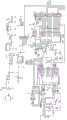
图1是本发明控制模块实施例1的结构原理框图。Fig. 1 is a structural principle block diagram of
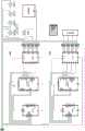
图2是本发明控制模块实施例2的结构原理框图。Fig. 2 is a structural principle block diagram of
图3是本发明控制模块实施例1采用载波传输模块PN532 NFC板的电路原理图。Fig. 3 is a schematic circuit diagram of the carrier transmission module PN532 NFC board used in
图4是本发明控制模块实施例1采用微控制器Arduino UNO Rev3开发板的电路原理图一。Fig. 4 is a schematic circuit diagram 1 of the microcontroller Arduino UNO Rev3 development board used in
图5是本发明控制模块实施例1采用微控制器Arduino UNO Rev3开发板的电路原理图二。Fig. 5 is the circuit schematic diagram 2 of the microcontroller Arduino UNO Rev3 development board used in
图6本发明门锁中控装置电路原理图。Fig. 6 is a circuit schematic diagram of the door lock central control device of the present invention.
图7是中控装置安装结构示意图。Fig. 7 is a schematic diagram of the installation structure of the central control device.
图8是门把手NFC天线安装结构示意图。Fig. 8 is a schematic diagram of the installation structure of the door handle NFC antenna.
具体实施方式Detailed ways
下面结合附图实施例对本发明作进一步详述:The present invention will be described in further detail below in conjunction with accompanying drawing embodiment:
本发明包括搭载NFC功能的移动设备、控制模块、四路继电器板,所述控制模块包括微控制器、载波传输模块,其中微控制器通过串行外设接口SPI、集成电路总线IIC或者通用异步收发传输总线高速UART(HSU)和载波传输模块进行交互;所述载波传输模块用于识别卡ID,所述微控制器用于将载波传输模块识别的ID与程序内的ID进行比对,比对正确,向四路继电器板中1-4继电器的通断,从而控制门锁电机或者点火开关的状态。其中:微控制器采用Arduino UNO Rev3开发板,所述载波传输模块采用带天线的PN532 NFC板。The invention includes a mobile device equipped with NFC function, a control module, and a four-way relay board. The control module includes a microcontroller and a carrier transmission module. The high-speed UART (HSU) of the transceiver transmission bus interacts with the carrier transmission module; the carrier transmission module is used to identify the card ID, and the microcontroller is used to compare the ID identified by the carrier transmission module with the ID in the program, and compare Correct, turn on and off the 1-4 relays in the four-way relay board to control the state of the door lock motor or the ignition switch. Wherein: the microcontroller adopts Arduino UNO Rev3 development board, and the carrier transmission module adopts PN532 NFC board with antenna.
如图4、5所示,由图4中的1、2、3、4、5、6端口连接图5的1、2、3、4、5、6端口,就组成本发明一个完整的Arduino UNO Rev3电路图。Arduino UNO Rev3是基于集成电路(IC)ATmega328P的单片机开发板,ATmega328P是一款高性能、低功耗AVR 8位微控制器,最后的P意为PicoPower,是一种节能技术,能够降低芯片的功耗。ATmega328P基于先进的RISC体系结构,封装了中央处理器单元CPU、时钟CLOCK、内存阵列RAM。As shown in Figures 4 and 5,
PN532 NFC板是恩智浦半导体公司NXP Semiconductors(原飞利浦半导体)出品的一款高度集成的13.56MHz载波传输模块。The PN532 NFC board is a highly integrated 13.56MHz carrier transmission module produced by NXP Semiconductors (formerly Philips Semiconductors).
基于上述基本技术,本发明有两种实施例:Based on above-mentioned basic technology, the present invention has two kinds of embodiments:
实施例1:Example 1:
如图1所示,使用了两套完全相同的模块分别实现门锁控制和点火控制功能,每个模块都单独含有一套如图3所示的PN532板、如图4、5(采用1、2、3、4、5、6端连接后)连接组成的Arduino UNO板、继电器板,电源给两块Arduino UNO板分别单独供电,两块PN532板及两块继电器板则由Arduino UNO板提供电力。负责门锁控制的PN532使用天线分离式,将天线单独安装在车门把手中,负责点火控制的模块则使用天线一体式,板上自带天线电路。As shown in Figure 1, two sets of identical modules are used to realize door lock control and ignition control functions respectively, and each module contains a set of PN532 boards as shown in Figure 3, as shown in Figure 4 and 5 (
实施例2:Example 2:
如图2所示,与方案一不同的是,方案二并没有使用单独的PN532板和Arduino UNO板控制车辆发动机启停,而是与门锁控制部分共用PN532板与Arduino UNO板。不论是控制门锁开闭还是发动机启停均要从同一个PN532上识别。电源给Arduino UNO板单独供电,PN532板及两块继电器板则由Arduino UNO板提供电力。PN532板使用板上自带天线电路加外接天线的双天线版本,将分离式天线单独安装在车门把手中,板上的一体式天线负责识别点火控制信号。As shown in Figure 2, different from
下面以图1所示的实施例对本发明进行详细说明:The present invention is described in detail below with the embodiment shown in Fig. 1:
控制模块采用两块,四路继电器板采用两块,每个控制模块连接一块四路继电器板,其中一块四路继电器板控制门锁电机,另一块四路继电器板控制点火开关的状态。Two control modules and two four-way relay boards are used. Each control module is connected to a four-way relay board. One of the four-way relay boards controls the door lock motor, and the other four-way relay board controls the state of the ignition switch.
对图1所示结构的基本控制方法为:包括步骤:The basic control method to the structure shown in Figure 1 is: comprise steps:
系统搭建步骤:采用搭载NFC功能的移动设备、控制模块、四路继电器板组成系统,控制模块包括微控制器、载波传输模块,其中微控制器通过串行外设接口SPI、集成电路总线IIC或者通用异步收发传输总线高速UART(HSU)和载波传输模块进行交互;微控制器采用Arduino UNO Rev3开发板:载波传输模块采用带天线的PN532 NFC板,其中:微控制器的引脚A4、A5、2、3对应与载波传输模块引脚MO/SDA/TX、NSS/SCL/RX、IRO、RST#连接;微控制器使用Arduino语言,与载波传输模块选用IIC协议通讯。System construction steps: A mobile device equipped with NFC function, a control module, and a four-way relay board are used to form a system. The control module includes a microcontroller and a carrier transmission module. The universal asynchronous transceiver transmission bus high-speed UART (HSU) interacts with the carrier transmission module; the microcontroller adopts the Arduino UNO Rev3 development board: the carrier transmission module adopts the PN532 NFC board with antenna, in which: the microcontroller pins A4, A5, 2 and 3 correspond to the connection with the pins MO/SDA/TX, NSS/SCL/RX, IRO, RST# of the carrier transmission module; the microcontroller uses the Arduino language, and uses the IIC protocol to communicate with the carrier transmission module.
对图1所示结构的详细实施例如下:The detailed embodiment to the structure shown in Figure 1 is as follows:
控制模块中的微控制器采用Arduino UNO Rev3开发板,Arduino UNO Rev3开发板具有数字信号I/O引脚孔14路,其中可提供脉冲宽度调制PWM输出的引脚孔6路。模拟信号输入引脚孔6路、16MHz石英晶振一个、通用串行总线USB接口一个、在线串行编程ICSP数据接口一个、DC 2.1mm母头电源插座一个、以及RESET复位按钮组成。只需将计算机通过USB数据线与其连接,或利用交-直流电源适配器,亦或通过电池提供电力后即可启动运行。ArduinoUNO中包括了单片机运行的全部要素。The microcontroller in the control module uses the Arduino UNO Rev3 development board. The Arduino UNO Rev3 development board has 14 digital signal I/O pin holes, of which 6 pin holes can provide pulse width modulation PWM output. It consists of 6 channels of analog signal input pin holes, a 16MHz quartz crystal oscillator, a USB interface for universal serial bus, an ICSP data interface for in-circuit serial programming, a DC 2.1mm female power socket, and a RESET reset button. Just connect the computer to it through the USB data cable, or use the AC-DC power adapter, or provide power through the battery to start operation. ArduinoUNO includes all the elements of single-chip operation.
将ATmega16U2编程配置为通用串行总线与串行接口USB to Serial的转换器,这样便能更简便、轻松自如地安装驱动程序软件。Arduino UNO中的ATmega328P集成电路已进行预编程处理,亦配有引导程序(占用0.5KB存储空间),允许用户不必使用外部硬件编程器,就能直接给开发板上传新的代码。其具备存储空间32KB,其中引导程序占用0.5KB。以及SRAM 2KB和EEPROM 1KB,可以通过EEPROM库读取和写入。The ATmega16U2 is programmed and configured as a USB to Serial converter between the Universal Serial Bus and the serial interface, so that the driver software can be installed more easily and easily. The ATmega328P integrated circuit in the Arduino UNO has been pre-programmed and is also equipped with a bootloader (occupies 0.5KB storage space), allowing users to upload new codes directly to the development board without using an external hardware programmer. It has a storage space of 32KB, of which the bootloader occupies 0.5KB. And SRAM 2KB and EEPROM 1KB, which can be read and written by EEPROM library.
Arduino UNO Rev3开发板具有自动选择电源的功能,可以通过连接其USB接口提供电力,或是采用交-直电源适配器(Wall-Wart)或者电池等外部电源(非USB)供电。可以将交-直电源适配器(Wall-Wart)通过线缆连接到DC 5.5*2.1mm的公头插头上,插入开发板的DC 2.1mm母头电源插座给开发板提供电力。使用电池供电时,则可将电池导线连接到开发板的VIN和GND引脚孔上。总的来说,三种方法向开发板供电,分别是USB接口(DC 5V)、DC2.1mm母头电源插座(DC 7~12V)或开发板的VIN引脚(DC 7~12V)。The Arduino UNO Rev3 development board has the function of automatically selecting a power source, which can be powered by connecting its USB interface, or using an external power source (non-USB) such as an AC-DC power adapter (Wall-Wart) or a battery. You can connect the AC-DC power adapter (Wall-Wart) to the DC 5.5*2.1mm male plug through a cable, and plug it into the DC 2.1mm female power socket of the development board to provide power for the development board. When using battery power, you can connect the battery wires to the VIN and GND pin holes of the development board. In general, there are three ways to supply power to the development board, which are USB interface (DC 5V), DC2.1mm female power socket (DC 7-12V) or the VIN pin of the development board (DC 7-12V).
Arduino UNO Rev3开发板的推荐电压范围为DC 7~12V。在外部电源电压为DC 6~20V时Arduino UNO都可启动运行。但若外部供电提供电压低于DC 7V,则开发板上的DC5V引脚的实际电压可能将不足DC 5V,这种状况将可能导致Arduino UNO开发板不能运行在最佳状态,影响开发板工作的稳定性。但若外部供电提供电压高于DC 12V,板上的电源稳压器可能会因过热而烧坏,使Arduino UNO开发板电源组件损坏。The recommended voltage range of the Arduino UNO Rev3 development board is
Arduino UNO开发板上的14路数字引脚Digital Pins中,每路都可作为数字信号输入INPUT或输出OUTPUT引脚。这可以通过使用引脚模式pinMode()、数字写入digitalWrite()和数字读取digitalRead()功能来实现。其各数字引脚的工作电压均为DC5V。各数字引脚可对外部提供或从外部接收20mA电流,设有默认处于断开状态的内部上拉电阻,阻值为20-50kΩ。最大允许通过电流为40mA,不得超过该值,以免使开发板受损。Among the 14 digital pins on the Arduino UNO development board, each channel can be used as a digital signal input INPUT or output OUTPUT pin. This can be achieved by using the pin mode pinMode(), digital writing digitalWrite() and digital reading digitalRead() functions. The working voltage of each digital pin is DC5V. Each digital pin can provide or receive 20mA current from the outside, and there is an internal pull-up resistor that is in the off state by default, and the resistance value is 20-50kΩ. The maximum allowable passing current is 40mA, which must not exceed this value, so as not to damage the development board.
Arduino UNO Rev3开发板配备有许多便于其与计算机、其他Arduino开发板或其他单片机通信的措施。ATmega328提供通用异步收发传输总线UART用于TTL串行通信(DC5V),这可以通过数字引脚0(RX)号和1(TX)号实现。Arduino UNO Rev3搭载的ATmega16U2芯片可以通过通用串行总线USB接通串行通信接口,并在计算机中提供一个软件模拟的COM端口(Windows系统要先配置一个.inf文件才能识别,而OSX和Linux系统将自动识别为COM端口)。Arduino IDE软件中包含有串口监视器,允许通过Arduino UNO Rev3开发板发送(RX)和接收(TX)一些简单的文本数据。当计算机和开发板通过ATmega16U2芯片和通用串行总线USB接口传输数据时,开发板上的RX(发送)和TX(接收)LED灯会闪烁。(数字引脚0(RX)号和1(TX)号上的串行通信不适用)。在Arduino UNO Rev3的任意一个数字引脚上,都可以通过软件串行库来实现串行通信。ATmega328P支持通用异步收发传输总线高速UART(HSU)、串行外设接口SPI以及集成电路总线IIC(TWI)通信。为了简化使用IIC总线的操作,Arduino IDE软件中包含有一个线库。The Arduino UNO Rev3 development board is equipped with many measures to facilitate its communication with computers, other Arduino development boards or other microcontrollers. ATmega328 provides UART for TTL serial communication (DC5V), which can be realized through digital pin 0 (RX) and 1 (TX). The ATmega16U2 chip on the Arduino UNO Rev3 can connect to the serial communication interface through the Universal Serial Bus USB, and provide a software-simulated COM port in the computer (Windows systems must first configure an .inf file to recognize it, while OSX and Linux systems will automatically be recognized as a COM port). The Arduino IDE software includes a serial monitor that allows sending (RX) and receiving (TX) some simple text data through the Arduino UNO Rev3 development board. When the computer and the development board transmit data through the ATmega16U2 chip and the USB interface of the Universal Serial Bus, the RX (transmit) and TX (receive) LED lights on the development board will blink. (Serial communication on digital pins 0 (RX) and 1 (TX) is not applicable). On any digital pin of Arduino UNO Rev3, serial communication can be realized through the software serial library. ATmega328P supports general asynchronous transmission bus high-speed UART (HSU), serial peripheral interface SPI and integrated circuit bus IIC (TWI) communication. In order to simplify the operation of using the IIC bus, a wire library is included in the Arduino IDE software.
载波传输模块采用带天线的PN532 NFC板,带天线的PN532 NFC板基于80C51内核,配备有ROM 40KB和RAM 1KB。带天线的PN532 NFC板的硬件接口有:串行外设接口SPI、集成电路总线IIC、通用异步收发传输总线高速UART(HSU)。The carrier transmission module adopts PN532 NFC board with antenna, and the PN532 NFC board with antenna is based on 80C51 core, equipped with ROM 40KB and RAM 1KB. The hardware interfaces of the PN532 NFC board with antenna include: serial peripheral interface SPI, integrated circuit bus IIC, and universal asynchronous transceiver transmission bus high-speed UART (HSU).
带天线的PN532 NFC板可以通过两个引脚来选择其三个配置模式:The PN532 NFC board with antenna can select its three configuration modes through two pins:
标准模式:带天线的PN532 NFC板的默认模式Standard Mode: Default mode for PN532 NFC board with antenna
仿真模式:带天线的PN532 NFC板在仿真模式下用串口RS232恒定波特率9.6kbps。支持IRQ引脚仿真,中断发生时P70_IRQ引脚为低电平。Emulation mode: PN532 NFC board with antenna uses serial port RS232 constant baud rate 9.6kbps in emulation mode. Support IRQ pin emulation, P70_IRQ pin is low level when interrupt occurs.
射频场开启模式:带天线的PN532 NFC板在射频场开启模式下,复位后PN532立即开启射频。P33_INT1引脚和P34/SIC_CLK引脚可以选择调制方式以及波特率,连续发送字节数据。在该模式下,温度传感器不可用。RF field open mode: PN532 NFC board with antenna is in RF field open mode, PN532 will open the radio frequency immediately after reset. The P33_INT1 pin and the P34/SIC_CLK pin can select the modulation mode and baud rate, and continuously send byte data. In this mode, the temperature sensor is not available.
带天线的PN532 NFC板的工作模式:带天线的PN532 NFC板可通过固件切换五种不同工作模式,以满足各种需要。分别是模拟卡、发起者/PCD、目标卡/PICC、低电量、待机。或者根据主控器(单片机)命令及PN532内部状态切换工作模式。Working mode of PN532 NFC board with antenna: PN532 NFC board with antenna can switch five different working modes through firmware to meet various needs. They are Sim Card, Initiator/PCD, Target Card/PICC, Low Battery, Standby. Or switch the working mode according to the command of the main controller (single chip microcomputer) and the internal state of PN532.
带天线的PN532 NFC板被配置成目标卡/PICC模式。若有目标卡被激活,PN532即从目标卡/PICC模式进入发起者/PCD模式。PN532 NFC board with antenna configured in target card/PICC mode. If a target card is activated, the PN532 enters the initiator/PCD mode from the target card/PICC mode.
主控器接口设置为:The main controller interface is set to:
系统的Arduino UNO Rev3开发板可以通过串行外设接口SPI、集成电路总线IIC或者通用异步收发传输总线高速UART(HSU)和PN532进行交互。通过16、17号引脚,选择主控器接口的通信连接方式。The Arduino UNO Rev3 development board of the system can interact with PN532 through serial peripheral interface SPI, integrated circuit bus IIC or universal asynchronous receiving and receiving transmission bus high-speed UART (HSU). Through
主控器接口选择如下:The main controller interface selection is as follows:

若使用串行外设接口SPI,又不接功率电源PVDD,则需进入低电压LowVbat模式。If you use the serial peripheral interface SPI and do not connect the power supply PVDD, you need to enter the low voltage LowVbat mode.
在载波传输模块(带天线的PN532 NFC板)和微控制器(Arduino UNO Rev3开发板)之间,除需连接通信接口之外,还需连接P70_IRQ引脚,便于有命令的时候,PN532可以快速通知控制器。Between the carrier transmission module (PN532 NFC board with antenna) and the microcontroller (Arduino UNO Rev3 development board), in addition to the communication interface, the P70_IRQ pin needs to be connected, so that when there are commands, the PN532 can quickly Notify the controller.
微控制器(Arduino UNO Rev3开发板)和载波传输模块(带天线的PN532 NFC板)的交互:Interaction between microcontroller (Arduino UNO Rev3 development board) and carrier transmission module (PN532 NFC board with antenna):
微控制器(Arduino UNO Rev3开发板)和载波传输模块(带天线的PN532 NFC板)之间实行半双工通信,半双工通信是轮流交替进行的双向通信,两个方向不能同时进行发送(TX)和接收(RX)。通信通过帧格式进行。帧类型共有五种:Half-duplex communication is implemented between microcontroller (Arduino UNO Rev3 development board) and carrier transmission module (PN532 NFC board with antenna). TX) and receive (RX). Communication takes place via frame format. There are five frame types:
(1)标准帧:双向传输的帧。命令从微控制器(Arduino UNO Rev3开发板)发送到PN532、响应从PN532发送到微控制器(Arduino UNO Rev3开发板),最大传输数据255 Byte。(1) Standard frame: a frame for bidirectional transmission. The command is sent from the microcontroller (Arduino UNO Rev3 development board) to the PN532, the response is sent from the PN532 to the microcontroller (Arduino UNO Rev3 development board), and the maximum transmission data is 255 Bytes.
(2)扩展帧:双向传输的帧。数据小于255 Byte也可用扩展帧,此帧有效传输数据至多可达到264 Byte。(2) Extended frame: a frame for bidirectional transmission. The extended frame can also be used if the data is less than 255 Byte. This frame can effectively transmit data up to 264 Byte.
(3)ACK帧:双向传输的帧。响应帧可能是微控制器(Arduino UNO Rev3开发板)发送到PN532也可能是PN532发送到微控制器(Arduino UNO Rev3开发板)。(3) ACK frame: a frame for bidirectional transmission. The response frame may be sent from the microcontroller (Arduino UNO Rev3 development board) to the PN532 or from the PN532 to the microcontroller (Arduino UNO Rev3 development board).
(4)NACK帧:单向传输的帧。微控制器(Arduino UNO Rev3开发板)发送给PN532,通知PN532上一响应帧微控制器(Arduino UNO Rev3开发板)接收失败,让PN532将上一次的数据重新发送给控制器(单片机)。(4) NACK frame: a frame for unidirectional transmission. The microcontroller (Arduino UNO Rev3 development board) sends it to PN532 to notify PN532 that the last response frame microcontroller (Arduino UNO Rev3 development board) failed to receive, and let PN532 resend the last data to the controller (single-chip microcomputer).
(5)错误帧:单向传输的帧。PN532发送到微控制器(Arduino UNO Rev3开发板),通知微控制器(Arduino UNO Rev3开发板)在应用层有错误发生。(5) Error frame: a frame transmitted in one direction. The PN532 is sent to the microcontroller (Arduino UNO Rev3 development board) to notify the microcontroller (Arduino UNO Rev3 development board) that an error occurred in the application layer.
带天线的PN532 NFC板的命令:Commands for PN532 NFC board with antenna:
帧结构包含数据的类型和数量。输入INPUT:微控制器(Arduino UNO Rev3开发板)向PN532传输数据,输出OUTPUT:PN532向微控制器(Arduino UNO Rev3开发板)传输数据。PN532可以通过命令来将其配置成发起者/PCD模式或者是目标卡/PICC模式。下图给出了指令码“Command Code(CC)”,即微控制器(Arduino UNO Rev3开发板)到PN532的帧。The frame structure contains the type and amount of data. Input INPUT: microcontroller (Arduino UNO Rev3 development board) transmits data to PN532, output OUTPUT: PN532 transmits data to microcontroller (Arduino UNO Rev3 development board). PN532 can be configured as initiator/PCD mode or target card/PICC mode through commands. The figure below shows the instruction code "Command Code (CC)", that is, the frame from the microcontroller (Arduino UNO Rev3 development board) to the PN532.
单片机到PN532的帧为:The frame from MCU to PN532 is:
RF射频交互命令:RF radio frequency interactive command:
PN532处于发起者模式或是目标卡模式时,可以使用的命令将在下表中用“○”表示。When PN532 is in initiator mode or target card mode, the commands that can be used will be marked with "○" in the table below.
PN532 RF射频交互命令表如下The PN532 RF radio frequency interactive command table is as follows


接口的配置:Interface configuration:
带天线的PN532 NFC板上设置跳线即可选择其接口连接方式。PN532板支持三种连接方式,分别是UART、SPI、IIC。跳线SET0、SET1的设置位置与连接方式的对应关系如下表:The interface connection method can be selected by setting jumpers on the PN532 NFC board with antenna. The PN532 board supports three connection methods, namely UART, SPI, and IIC. The corresponding relationship between the setting position of the jumpers SET0 and SET1 and the connection mode is as follows:
各主控接口跳线设置表如下:The jumper setting table of each main control interface is as follows:

线路连接:Line connection:
微控制器(Arduino UNO Rev3开发板)使用Arduino语言,为了方便代码设置,Arduino UNO与PN532选用IIC协议通讯。IIC即Inter-Integrated Circuit(集成电路总线),IIC又称I2C,是二十世纪八十年代初由飞利浦半导体(现恩智浦半导体公司NXPSemiconductors)设计出来的一种同步串行总线,其具有简单、双向、二线制的特点,主要用来连接整体电路(ICS),多个芯片可以连接到同一IIC总线结构下,同时其中的每一块芯片都可作为数据传输的控制源,也就是说IIC是一种多向控制总线。这种总线类型使得信号传输总线接口得到一定程度的简化。The microcontroller (Arduino UNO Rev3 development board) uses Arduino language. In order to facilitate code setting, Arduino UNO and PN532 use IIC protocol for communication. IIC stands for Inter-Integrated Circuit (Integrated Circuit Bus), and IIC, also known as I2C, is a synchronous serial bus designed by Philips Semiconductors (now NXP Semiconductors) in the early 1980s. It has simple, The characteristics of two-way and two-wire system are mainly used to connect the overall circuit (ICS). Multiple chips can be connected to the same IIC bus structure. At the same time, each chip can be used as a control source for data transmission. That is to say, IIC is a A multidirectional control bus. This bus type simplifies the signal transmission bus interface to a certain extent.
按IIC协议连接PN532板和Arduino UNO板,接法如下表:Connect the PN532 board and the Arduino UNO board according to the IIC protocol, the connection method is as follows:
为了控制门锁的锁闭状态,需对门锁电机的启停、运转方向进行控制。故在装置中设置继电器模块。Arduino UNO与4路继电器板接法如下表:In order to control the locked state of the door lock, it is necessary to control the start, stop and running direction of the door lock motor. Therefore, a relay module is set in the device. The connection between Arduino UNO and 4-way relay board is as follows:
。.
运行逻辑设定:Operation logic setting:
一、门锁控制模块:1. Door lock control module:
为了实现门锁的开闭功能,装置模块1的PN532识别卡ID后与程序内预设的ID进行比对,与预设的ID1ID2ID3的比对结果分别控制继电器板1中1—4继电器的通断,从而控制门锁电机的状态。In order to realize the opening and closing function of the door lock, the PN532 of the
手机里设置好NFC卡模式,预存执行各操作时所需要的卡ID,执行开锁和锁闭操作时,先在手机App中点击该功能键,手机NFC模块开始进行卡模拟,这时用手机靠近装置的PN532天线,卡ID比对成功,装置即可按操作人意志执行对应操作。如卡ID比对失败,则车辆发出声光警报。Set the NFC card mode in the mobile phone, and pre-store the card ID required for each operation. When performing unlocking and locking operations, first click the function button in the mobile app, and the NFC module of the mobile phone will start to simulate the card. At this time, use the mobile phone to approach The device's PN532 antenna and card ID are successfully compared, and the device can perform corresponding operations according to the operator's will. If the card ID comparison fails, the vehicle will send out an audible and visual alarm.
1.比对符合预设的ID1则给引脚4一个高电位,信号经连线送至继电器板1的引脚S1,则继电器1得电吸合,2s后给引脚4一个低电位,则继电器1失电释放。这个动作的目的是给客室门锁电机的开锁工作提供电力。1. Compared with the preset ID1,
2.比对符合预设的ID2则给引脚5一个高电位,信号经连线送至继电器板1的引脚S2,则继电器2得电吸合,2s后给引脚5一个低电位,则继电器2失电释放。这个动作的目的是给客室门锁电机的闭锁工作提供电力。2. Compared with the preset ID2, a high potential is given to
3.比对符合预设的ID3则给引脚6一个高电位,信号经连线送至继电器板1的引脚S3,则继电器3得电吸合,2s后给引脚6一个低电位,则继电器3失电释放。这个动作的目的是给后备箱门锁电机的开锁工作提供电力。3. Compared with the preset ID3, a high potential is given to
4.当卡ID与程序内预设的ID1 ID2 ID3均不符合时,则给引脚7一个高电位,信号经连线送至继电器板1的引脚S4,则继电器4得电吸合,2s后给引脚7一个低电位,则继电器4失电释放。这个动作的目的是给防盗警报系统提供电力,让车辆发出声光警报提示可能被人非法入侵。4. When the card ID does not match the preset ID1 ID2 ID3 in the program, a high potential is given to the
二、点火控制模块:2. Ignition control module:
为了兼顾舒适性和安全性、提高设备集成度。该装置还具有控制车辆发动机启停的功能。此功能由另一套PN532、UNO、继电器板实现。装置模块2的PN532识别卡ID后与程序内预设的ID4进行比对,比对结果控制继电器板2中4—8继电器的通断,从而控制车辆电源的通断和发动机启停状态。In order to take into account comfort and safety, improve equipment integration. The device also has the function of controlling the start and stop of the vehicle engine. This function is realized by another set of PN532, UNO, relay board. The PN532 of the
汽车点火开关有0 OFF(LOCK)、1 ACC、2 ON、3 START四个作用位置。接下来将分启动、停机两个顺序逐一介绍每个作用位置的功能。The car ignition switch has four active positions: 0 OFF (LOCK), 1 ACC, 2 ON, and 3 START. Next, the function of each action position will be introduced one by one in two sequences: start and stop.
上车启动顺序(0-1-2-3-2):Start sequence on board (0-1-2-3-2):
当点火开关置于0 OFF(LOCK)位置时,只有此位置可以将车钥匙拔出,拔出钥匙时方向盘落锁,插入钥匙方向盘解锁,车内全部电器断电,发动机停机。车辆较长时间停驶或驾驶员需离开车辆锁车都应使用此位置。When the ignition switch is in the 0 OFF (LOCK) position, only this position can pull out the car key. When the key is pulled out, the steering wheel will be locked. Insert the key to unlock the steering wheel. All electrical appliances in the car will be powered off and the engine will stop. This position should be used when the vehicle is parked for an extended period of time or when the driver needs to leave the vehicle and lock it.
当点火开关置于1 ACC位置时,车内部分电器通电(如仪表、灯光、喇叭、雨刷、音响、点烟器12V电源等),ECU电源断电,发动机停机,临时停车时驾驶员在车上继续使用舒适功能,可根据需要将点火开关置于ACC位置。长时间在此位置使用车内电器可能造成蓄电池亏电,发动机不能启动。When the ignition switch is placed at the 1 ACC position, some electrical appliances in the car are energized (such as instruments, lights, horns, wipers, audio, cigarette lighter 12V power supply, etc.), the ECU power supply is cut off, the engine stops, and the driver is in the car when the car is temporarily parked. To continue using the comfort function on the vehicle, the ignition switch can be placed in the ACC position if required. Using the electrical appliances in the car in this position for a long time may cause the battery to lose power and the engine cannot be started.
当点火开关置于2 ON位置时,车内全部电器通电(在ACC的基础上增加空调通风机等电器),ECU上电并开始自检,油泵工作建立油压,点火系统也做好启动准备。如果长时间在发动机停机状态下在此位置使用车内电器,同样会造成蓄电池亏电,需加以注意。When the ignition switch is placed in the 2 ON position, all electrical appliances in the car are energized (air conditioner, ventilator and other electrical appliances are added on the basis of ACC), the ECU is powered on and starts self-test, the oil pump works to establish oil pressure, and the ignition system is also ready to start . If you use the electrical appliances in the car at this position for a long time when the engine is stopped, it will also cause the battery to lose power, so you need to pay attention.
当点火开关置于3 START位置时,手上需保持拧动的力度,3 START位置是向2 ON位置自复位的。3 START位在2 ON位的基础上接通起动机电源,起动机齿轮挂入飞轮带动发动机曲轴,点火系统开始工作,发动机启动。原本通电的部分电器断电(如12V点烟器电源等)以确保起动机的电力供应充足,总而保证发动机能够成功启动。When the ignition switch is placed in the 3 START position, the hand needs to maintain the strength of twisting, and the 3 START position is self-resetting to the 2 ON position. The 3 START position connects the starter power on the basis of the 2 ON position, the starter gear is hooked into the flywheel to drive the crankshaft of the engine, the ignition system starts to work, and the engine starts. Some electrical appliances that were originally energized are powered off (such as 12V cigarette lighter power supply, etc.) to ensure sufficient power supply to the starter, and in general to ensure that the engine can be started successfully.
看转速表、听声音判断发动机已启动成功后使点火开关从3 START位置自复位至2ON位置,发动机维持运转,由发电机向车上各部电器供电,并向蓄电池充电,此即为汽车的怠速工况,进入正常行驶前的预备工况。Look at the tachometer and listen to the sound to judge that the engine has started successfully, then reset the ignition switch from the 3 START position to the 2ON position, the engine keeps running, and the generator supplies power to the various electrical appliances on the car and charges the battery. This is the idle speed of the car. Working condition, entering the preparatory working condition before normal driving.
下车停机顺序(2-1-0):Getting off and stopping sequence (2-1-0):
当点火开关置于2 ON位置时,发动机维持运转,由发电机向车上各部电器供电,并向蓄电池充电,车辆处于怠速或行驶工况。When the ignition switch is placed in the 2 ON position, the engine keeps running, and the generator supplies power to various electrical appliances on the vehicle, and charges the battery, and the vehicle is in idling or driving condition.
当点火开关置于1 ACC位置时,发动机点火系统停止工作、发动机停机,ECU电源断电,车内部分电器通电(如仪表、灯光、喇叭、雨刷、音响、点烟器12V电源等)。供驾驶员临时停车使用舒适功能。When the ignition switch is placed at the 1 ACC position, the engine ignition system stops working, the engine stops, the ECU power supply is cut off, and some electrical appliances in the car are powered on (such as instruments, lights, horns, wipers, audio, cigarette lighter 12V power supply, etc.). A convenience function for the driver to use when parking temporarily.
当点火开关置于0 OFF(LOCK)位置时,车内全部电器断电,发动机停机,拔出钥匙时方向盘落锁,四门自动开锁。驾驶员需锁车离开车辆应使用此位置。When the ignition switch is placed in the 0 OFF (LOCK) position, all electrical appliances in the car are powered off, the engine stops, the steering wheel is locked when the key is pulled out, and the four doors are automatically unlocked. Drivers who need to lock and leave the vehicle should use this position.
装置对钥匙点火开关功能的替代实现:Alternative implementation of device to key ignition switch functionality:
比对符合预设的ID4则给引脚8一个高电位,信号经连线送至继电器板2的引脚S1,则继电器5得电吸合。此动作的目的是控制方向盘解锁。If ID4 conforms to the default, a high potential is given to the
延时0.5s后给引脚9一个高电位,则继电器6得电吸合。此动作的目的是接通点火开关的ACC电路。车内部分电器通电(如仪表、灯光、喇叭、雨刷、音响、点烟器12V电源等),ECU电源断电,发动机停机。Give pin 9 a high potential after a delay of 0.5s, and then relay 6 is energized and closed. The purpose of this action is to turn on the ACC circuit of the ignition switch. Some electrical appliances in the car are powered on (such as instruments, lights, horns, wipers, audio, cigarette lighter 12V power supply, etc.), the ECU power supply is powered off, and the engine stops.
延时1s后给引脚10一个高电位,则继电器7得电吸合。此动作的目的是接通点火开关的ON电路。车内全部电器通电(在ACC的基础上增加空调通风机等电器),ECU上电并开始自检,油泵工作建立油压,点火系统也做好启动准备。Give pin 10 a high potential after a delay of 1s, and then relay 7 is energized and closed. The purpose of this action is to turn on the ON circuit of the ignition switch. All electrical appliances in the car are energized (air conditioner, ventilator and other electrical appliances are added on the basis of ACC), the ECU is powered on and starts self-test, the oil pump works to establish oil pressure, and the ignition system is also ready to start.
延时2s后给引脚10一个高电位,则继电器8得电吸合,延时3s后给引脚10一个低电位,则继电器8失电释放。此动作的目的是接通点火开关的START电路。3 START位在2 ON位的基础上接通起动机电源,起动机齿轮挂入飞轮带动发动机曲轴,点火系统开始工作,发动机启动。原本通电的部分电器断电(如12V点烟器电源等)以确保起动机的电力供应充足,总而保证发动机能够成功启动。Give pin 10 a high potential after a delay of 2s, then the
本实施例中,载波传输模块的NFC天线安装在汽车11的前挡风玻璃或者门锁把手附近,NFC天线是环形线圈,嵌入安装在门把手12内部,也可在门把手注塑成型时将该天线封装在内;微控制器和四路继电器板安装在中控台下方隐藏空间13中,如图6、7所示。In this embodiment, the NFC antenna of the carrier transmission module is installed near the front windshield of the
Claims (2)

Applications Claiming Priority (2)
| Application Number | Priority Date | Filing Date | Title |
|---|---|---|---|
| CN2018105166389 | 2018-05-25 | ||
| CN201810516638 | 2018-05-25 |
Publications (2)
| Publication Number | Publication Date |
|---|---|
| CN109696869A CN109696869A (en) | 2019-04-30 |
| CN109696869Btrue CN109696869B (en) | 2023-06-30 |
Family
ID=66233062
Family Applications (1)
| Application Number | Title | Priority Date | Filing Date |
|---|---|---|---|
| CN201811650914.7AActiveCN109696869B (en) | 2018-05-25 | 2018-12-31 | Automobile central door lock control device and control method based on NFC near field communication technology |
Country Status (1)
| Country | Link |
|---|---|
| CN (1) | CN109696869B (en) |
Cited By (1)
| Publication number | Priority date | Publication date | Assignee | Title |
|---|---|---|---|---|
| US12149107B2 (en)* | 2021-09-01 | 2024-11-19 | Fortin Systèmes Électroniques | System and method using wireless latching relay for vehicle fleet management inventory |
Families Citing this family (5)
| Publication number | Priority date | Publication date | Assignee | Title |
|---|---|---|---|---|
| CN111799788A (en)* | 2020-07-14 | 2020-10-20 | 三一重机有限公司 | Power-off control system, engineering machinery and power-off control method |
| CN112233281A (en)* | 2020-09-29 | 2021-01-15 | 上汽通用五菱汽车股份有限公司 | Bluetooth key vehicle control method and system |
| CN114143754B (en)* | 2021-11-30 | 2024-10-22 | 上汽通用五菱汽车股份有限公司 | Method and device for reducing vehicle-mounted power consumption, vehicle and computer readable storage medium |
| CN115685596A (en)* | 2022-11-11 | 2023-02-03 | 康立光学科技(广州)有限公司 | Intelligent glasses and method for linkage of intelligent glasses and automobile |
| CN118280022A (en)* | 2024-03-25 | 2024-07-02 | 奇瑞汽车股份有限公司 | Vehicle unlocking system and method and NFC digital key management method |
Citations (7)
| Publication number | Priority date | Publication date | Assignee | Title |
|---|---|---|---|---|
| CN202872777U (en)* | 2012-09-17 | 2013-04-10 | 浙江吉利汽车研究院有限公司杭州分公司 | Automobile gating system based on NFC technology |
| DE102012101836A1 (en)* | 2012-03-05 | 2013-09-05 | Oliver Lünstedt | Mobile-based additional electronic immobilizer with door opener with theft alarm |
| CN103625425A (en)* | 2012-08-21 | 2014-03-12 | 通用汽车环球科技运作有限责任公司 | System for passive entry and passive start using near field communication |
| CN203854621U (en)* | 2014-04-18 | 2014-10-01 | 深圳市威富安防有限公司 | Intelligent anti-theft start system for vehicle |
| CN204590935U (en)* | 2015-04-23 | 2015-08-26 | 朱周贤 | A kind of automobile automatic window-closing circuit |
| US9544853B1 (en)* | 2016-03-21 | 2017-01-10 | GM Global Technology Operations LLC | Method and system for selectively activating a vehicle near field communication module |
| CN107187421A (en)* | 2016-03-15 | 2017-09-22 | 通用汽车环球科技运作有限责任公司 | Keyless entry and starting system |
- 2018
- 2018-12-31CNCN201811650914.7Apatent/CN109696869B/enactiveActive
Patent Citations (7)
| Publication number | Priority date | Publication date | Assignee | Title |
|---|---|---|---|---|
| DE102012101836A1 (en)* | 2012-03-05 | 2013-09-05 | Oliver Lünstedt | Mobile-based additional electronic immobilizer with door opener with theft alarm |
| CN103625425A (en)* | 2012-08-21 | 2014-03-12 | 通用汽车环球科技运作有限责任公司 | System for passive entry and passive start using near field communication |
| CN202872777U (en)* | 2012-09-17 | 2013-04-10 | 浙江吉利汽车研究院有限公司杭州分公司 | Automobile gating system based on NFC technology |
| CN203854621U (en)* | 2014-04-18 | 2014-10-01 | 深圳市威富安防有限公司 | Intelligent anti-theft start system for vehicle |
| CN204590935U (en)* | 2015-04-23 | 2015-08-26 | 朱周贤 | A kind of automobile automatic window-closing circuit |
| CN107187421A (en)* | 2016-03-15 | 2017-09-22 | 通用汽车环球科技运作有限责任公司 | Keyless entry and starting system |
| US9544853B1 (en)* | 2016-03-21 | 2017-01-10 | GM Global Technology Operations LLC | Method and system for selectively activating a vehicle near field communication module |
Cited By (1)
| Publication number | Priority date | Publication date | Assignee | Title |
|---|---|---|---|---|
| US12149107B2 (en)* | 2021-09-01 | 2024-11-19 | Fortin Systèmes Électroniques | System and method using wireless latching relay for vehicle fleet management inventory |
Also Published As
| Publication number | Publication date |
|---|---|
| CN109696869A (en) | 2019-04-30 |
Similar Documents
| Publication | Publication Date | Title |
|---|---|---|
| CN109696869B (en) | Automobile central door lock control device and control method based on NFC near field communication technology | |
| CN102673517B (en) | Automobile owner identification device, control system and control method based on near field communication (NFC) mobile phone | |
| CN101974991B (en) | Vehicle intelligent lock, intelligent key and starting method | |
| US9842444B2 (en) | Phone sleeve vehicle fob | |
| CN102733674B (en) | Automobile inner control device for automotive keyless entry and start system | |
| CN103774917A (en) | Remote function fob for a vehicle passive entry passive start system and method for operating same | |
| CN201883792U (en) | Vehicle key-free entering and starting system | |
| CN103625425A (en) | System for passive entry and passive start using near field communication | |
| CN106341147A (en) | Intelligent vehicle-mounted system based on mobile terminal | |
| CN112660069B (en) | Vehicle starting method, vehicle-mounted terminal and vehicle | |
| CN205063572U (en) | Energy -conserving electronic lock | |
| CN202593445U (en) | Automobile entrance start-up system | |
| KR101270625B1 (en) | Control method of vehicles using Blooth communication | |
| CN109672479A (en) | It is a kind of to charge for eliminating onboard wireless to the PEPS control system interfered and control method | |
| CA2942498C (en) | Multi-adaptor vehicle remote function controller and associated methods | |
| CN210011725U (en) | Automobile central door lock control device based on NFC (near field communication) technology | |
| CN204586742U (en) | The startup control system of automobile | |
| CN204279356U (en) | A car bluetooth built-in lock | |
| CN110667514B (en) | Vehicle door unlocking method and device | |
| CN108265647B (en) | Parking space lock device, system and use method of parking space lock device | |
| CN1971629A (en) | Occupant approach detection apparatus, occupant approach detection system, and occupant approach detection method | |
| CN222125773U (en) | Keyless entry device for vehicle | |
| CN202794977U (en) | Matching support device, special external device and automobile | |
| CN102029973B (en) | Automobile body controller with engine burglary-prevention function | |
| JP2009148041A (en) | Plug-in vehicle charging system |
Legal Events
| Date | Code | Title | Description |
|---|---|---|---|
| PB01 | Publication | ||
| PB01 | Publication | ||
| SE01 | Entry into force of request for substantive examination | ||
| SE01 | Entry into force of request for substantive examination | ||
| GR01 | Patent grant | ||
| GR01 | Patent grant |