CN109696191B - Movement delay measurement method of virtual reality head-mounted display equipment - Google Patents
Movement delay measurement method of virtual reality head-mounted display equipmentDownload PDFInfo
- Publication number
- CN109696191B CN109696191BCN201811636718.4ACN201811636718ACN109696191BCN 109696191 BCN109696191 BCN 109696191BCN 201811636718 ACN201811636718 ACN 201811636718ACN 109696191 BCN109696191 BCN 109696191B
- Authority
- CN
- China
- Prior art keywords
- black
- mounted display
- head
- white
- display device
- Prior art date
- Legal status (The legal status is an assumption and is not a legal conclusion. Google has not performed a legal analysis and makes no representation as to the accuracy of the status listed.)
- Active
Links
- 238000000691measurement methodMethods0.000titleclaimsabstractdescription7
- 238000000034methodMethods0.000claimsabstractdescription34
- 230000003287optical effectEffects0.000claimsabstractdescription29
- 238000005259measurementMethods0.000claimsabstractdescription5
- 238000001514detection methodMethods0.000claimsdescription15
- 230000008569processEffects0.000claimsdescription12
- 230000009191jumpingEffects0.000claimsdescription8
- 238000005070samplingMethods0.000claimsdescription7
- 230000001934delayEffects0.000claimsdescription4
- 238000006243chemical reactionMethods0.000abstractdescription5
- 238000012360testing methodMethods0.000abstractdescription3
- 230000007704transitionEffects0.000description9
- 238000010586diagramMethods0.000description5
- 238000012935AveragingMethods0.000description2
- 238000012545processingMethods0.000description2
- 230000009286beneficial effectEffects0.000description1
- 230000008859changeEffects0.000description1
- 238000005516engineering processMethods0.000description1
- 230000006872improvementEffects0.000description1
- 238000009434installationMethods0.000description1
- 238000012986modificationMethods0.000description1
- 230000004048modificationEffects0.000description1
- 201000003152motion sicknessDiseases0.000description1
- 230000002093peripheral effectEffects0.000description1
- 230000000630rising effectEffects0.000description1
- 208000024891symptomDiseases0.000description1
- 238000010998test methodMethods0.000description1
Images


Classifications
- G—PHYSICS
- G01—MEASURING; TESTING
- G01D—MEASURING NOT SPECIALLY ADAPTED FOR A SPECIFIC VARIABLE; ARRANGEMENTS FOR MEASURING TWO OR MORE VARIABLES NOT COVERED IN A SINGLE OTHER SUBCLASS; TARIFF METERING APPARATUS; MEASURING OR TESTING NOT OTHERWISE PROVIDED FOR
- G01D5/00—Mechanical means for transferring the output of a sensing member; Means for converting the output of a sensing member to another variable where the form or nature of the sensing member does not constrain the means for converting; Transducers not specially adapted for a specific variable
- G01D5/26—Mechanical means for transferring the output of a sensing member; Means for converting the output of a sensing member to another variable where the form or nature of the sensing member does not constrain the means for converting; Transducers not specially adapted for a specific variable characterised by optical transfer means, i.e. using infrared, visible, or ultraviolet light
- G—PHYSICS
- G01—MEASURING; TESTING
- G01B—MEASURING LENGTH, THICKNESS OR SIMILAR LINEAR DIMENSIONS; MEASURING ANGLES; MEASURING AREAS; MEASURING IRREGULARITIES OF SURFACES OR CONTOURS
- G01B11/00—Measuring arrangements characterised by the use of optical techniques
- G01B11/26—Measuring arrangements characterised by the use of optical techniques for measuring angles or tapers; for testing the alignment of axes
Landscapes
- Physics & Mathematics (AREA)
- General Physics & Mathematics (AREA)
- Position Input By Displaying (AREA)
- Length Measuring Devices By Optical Means (AREA)
Abstract
Translated fromChinese
Description
Translated fromChinese技术领域technical field
本发明属于虚拟现实设备技术领域,具体涉及一种虚拟现实头戴显示设备的移动延迟测量方法。The invention belongs to the technical field of virtual reality devices, and in particular relates to a movement delay measurement method of a virtual reality head-mounted display device.
背景技术Background technique
头戴显示设备(HMD)的延迟时间与用户的使用体验息息相关,如果时间稍大则可能会引发使用者产生“晕动症”症状。文献“Luca M D.New Method to Measure End-to-EndDelay of Virtual Reality[M].MIT Press,2010.”提出了一个延迟测量的简易方案,如图1(a)所示,在HMD外壳与视窗上各固定一个光敏传感器,在显示屏与HMD中都显示出一个灰度渐变的测试图,然后将外壳上的光敏传感器紧贴显示屏,令HMD紧贴显示屏并沿着灰度变化方向往复运动,记录下两个传感器返回的波形(图1(b))。通过计算两个波形之间的相位差,得到该HMD的延迟时间。该方法的缺陷是,需要手动移动,移动过程中的抖动等会给后边的信号处理引入许多噪声;使用手动对齐频域波形的方法解决虚拟空间中图样与显示屏中图样不同步引入的误差,依靠肉眼判断,对于延迟时间这种微小的时间,这种方法有时不仅不能消除误差,反而会引入新的误差;该测试方法对于头盔有遮挡,HMD需要其能在如此多遮蔽的情况下计算自身的位置数据,这对许多HMD的跟踪方案是不友好的;所得到的数据有较大的方差,其不稳定性决定其不能够被用来制作测量仪器。The delay time of the head-mounted display device (HMD) is closely related to the user's experience. If the delay time is slightly longer, the user may experience "motion sickness" symptoms. The document "Luca M D. New Method to Measure End-to-EndDelay of Virtual Reality [M]. MIT Press, 2010." proposes a simple solution for delay measurement, as shown in Figure 1(a). One photosensitive sensor is fixed on each window, and a grayscale gradient test pattern is displayed on both the display screen and the HMD, and then the photosensitive sensor on the casing is close to the display screen, so that the HMD is close to the display screen and follows the grayscale change direction. Reciprocating motion, record the waveforms returned by the two sensors (Fig. 1(b)). The delay time of the HMD is obtained by calculating the phase difference between the two waveforms. The disadvantage of this method is that manual movement is required, and jitter during the movement will introduce a lot of noise to the subsequent signal processing; the method of manually aligning the frequency domain waveform is used to solve the error caused by the asynchronous pattern in the virtual space and the pattern in the display screen. Relying on the judgment of the naked eye, for such a small delay time, this method sometimes not only fails to eliminate errors, but also introduces new errors; this test method has occlusions for helmets, and HMD needs to be able to calculate itself in the case of so many occlusions This is not friendly to many HMD tracking schemes; the obtained data has a large variance, and its instability determines that it cannot be used to make measuring instruments.
发明内容SUMMARY OF THE INVENTION
有鉴于此,本发明的目的是提供一种虚拟现实头戴显示设备的移动延迟测量方法,可以通过简单的设备准确测量VR头盔的移动延迟。In view of this, the purpose of the present invention is to provide a movement delay measurement method of a virtual reality head-mounted display device, which can accurately measure the movement delay of the VR helmet through a simple device.
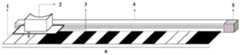
一种虚拟现实头戴显示设备的移动延迟测量方法,使用的测量装置包括第一光敏传感器(1)、头戴显示设备(2)、载物台(3)、数控导轨(4)、导轨控制器(5)、光编码板(6)以及第二光敏传感器(7);数控导轨(4)的一侧放置光编码板(6),光编码板(6)上设置有编码图形,编码图形为间隔排列的黑白条纹;数控导轨(4)的载物台(3)在导轨控制器(5)的控制下可沿轨道直线运动,第一光敏传感器(1)和头戴显示设备(2)固定在载物台(3)上,其中,第一光敏传感器(1)在跟随载物台(3)运动过程可感知光编码板(6)上的黑白条纹;第二光敏传感器(7)固定在头戴显示设备(2)的显示窗口上;A method for measuring movement delay of a virtual reality head-mounted display device, using a measurement device comprising a first photosensitive sensor (1), a head-mounted display device (2), a stage (3), a numerically controlled guide rail (4), a guide rail control device (5), optical encoding plate (6) and second photosensitive sensor (7); an optical encoding plate (6) is placed on one side of the numerical control guide rail (4), and an encoding graphic is arranged on the optical encoding plate (6). are black and white stripes arranged at intervals; the stage (3) of the numerically controlled guide rail (4) can move linearly along the track under the control of the guide rail controller (5), the first photosensitive sensor (1) and the head-mounted display device (2) is fixed on the stage (3), wherein the first photosensitive sensor (1) can perceive the black and white stripes on the optical coding plate (6) during the movement process of the stage (3); the second photosensitive sensor (7) is fixed on the display window of the head-mounted display device (2);
所述移动延迟测量方法具体步骤如下:The specific steps of the mobile delay measurement method are as follows:
步骤1、先控制载物台(3)从初始位置沿数控导轨(4)匀速运动,头戴显示设备(2)实时计算自身位置;
步骤2、在载物台(3)运动过程中,第一光敏传感器(1)感知光编码板(6)上的黑白条纹,在感知到黑条纹转变到白条纹,以及白条纹转变到黑条纹的转换时刻,头戴显示设备(2)计算出在各个转换时刻的自身位置,并记录下来;其中,自身位置包括两种:黑条纹转变到白条纹的位置定义为黑到白位置,白条纹转变到黑条纹的位置定义为白到黑位置;
步骤3、完成运动后,得到一组头戴显示设备(2)的位置数据集;
步骤4、控制载物台(3)再次从初始位置开始匀速移动,运动过程中头戴显示设备(2)实时计算自身位置,同时记录第一光敏传感器(1)与第二光敏传感器(7)返回的数据;
步骤5、根据之前记录的位置数据集,头戴显示设备(2)结合计算的自身当前位置信息,头戴显示设备(2)显示对应的黑白画面,即:当计算的位置为白到黑位置,向头戴显示设备(2)输出黑色图案;当计算的位置为黑到白位置,向头戴显示设备(2)输出白色图案;其上的第二光敏传感器(7)在此过程中,感知头戴显示设备(2)镜头输出的黑白图像,当感知到白色图像时,第二光敏传感器(7)返回高电平,当感知到黑色图像时,第二光敏传感器(7)返回低电平;
步骤6、与此同时,第一光敏传感器(1)在移动过程中感知光编码板(6)上的编码图形,感知到白色条纹时,第一光敏传感器(1)返回高电平,当感知到黑色条纹时,第一光敏传感器(1)返回低电平;
步骤7、完成移动后,得到两组方波信号:由第一光敏传感器(1)返回的波形称之为参考波形,由第二光敏传感器(7)返回的波形称之为检测波形;
步骤8、计算检测波形相对于参考波形的时间延迟Δt,即为头戴显示设备(2)的时间延迟。Step 8: Calculate the time delay Δt of the detected waveform relative to the reference waveform, which is the time delay of the head mounted display device (2).
进一步的,所述步骤8中,对参考波形和检测波形进行线性拟合,然后进行采样,具体方法为:Further, in the
A、从左到右依次给光编码板(6)上编码区部分的黑白条纹图案的分界线赋予编号,即1号分界线、2号分界线等;则基于光编码板(6)获得的参考波形、与参考波形对应的检测波形的各个跳变沿也对应取得编号;A, sequentially from left to right give numbers to the dividing line of the black and white striped pattern of the coding area part on the optical coding plate (6), namely No. 1 dividing line, No. 2 dividing line, etc.; then obtain based on the optical coding plate (6) The reference waveform and each transition edge of the detection waveform corresponding to the reference waveform are also numbered correspondingly;
B、以时间为x轴,编号为y轴建立坐标系,以参考波形方波跳变沿的时间信息为x坐标,以跳变沿的编号值为y坐标,以此在坐标系中绘制得到表征跳变沿编号和时间的离散点;同理,得到检测波形各跳变沿对应的离散点;B. Take the time as the x-axis and the number as the y-axis to establish a coordinate system, take the time information of the jumping edge of the reference waveform square wave as the x-coordinate, and use the number of the jumping edge as the y-coordinate to draw in the coordinate system The discrete points representing the transition edge number and time; in the same way, the discrete points corresponding to each transition edge of the detected waveform are obtained;
C、分别对两组离散点进行线性拟合,得到两条曲线,通过对y值进行设定步长的采样,得到同一y值下两曲线间x轴的坐标差值,即检测波形相对于参考波形的一个延迟时间数据;对y轴有效区间进行多次采样后,得到多个延迟时间数据并求取均值,即得到头戴显示设备(2)的精确时间延迟量。C. Perform linear fitting on the two sets of discrete points respectively to obtain two curves. By sampling the y value with a set step size, the coordinate difference of the x-axis between the two curves under the same y value is obtained, that is, the detected waveform is relative to the A delay time data of the reference waveform; after sampling the effective interval of the y-axis for many times, multiple delay time data are obtained and an average value is obtained, that is, the precise time delay amount of the head mounted display device (2) is obtained.
进一步的,控制载物台(3)在导轨(4)上反复运动,获得多条参考波形和检测波形曲线,由此得到多个延迟Δt,取平均后,均值作为头戴显示设备(2)的精确时间延迟量。Further, the stage (3) is controlled to move repeatedly on the guide rail (4) to obtain a plurality of reference waveforms and detection waveform curves, thereby obtaining a plurality of delays Δt, and after averaging, the average value is used as the head-mounted display device (2) The exact amount of time delay.
进一步的,在光编码板(6)的编码图形两端各设置一个信息头,由黑白条纹按一定排布顺序组合而成;在载物台(3)正向移动和反向移动经过信息头时,第一光敏传感器(1)感知到两个信息头的不同编码,由此区分载物台(3)的运动方向。Further, an information head is provided at both ends of the coding pattern of the optical coding plate (6), which is composed of black and white stripes in a certain order; When , the first photosensitive sensor (1) senses the different codes of the two information headers, thereby distinguishing the moving direction of the stage (3).
本发明具有如下有益效果:The present invention has the following beneficial effects:
本发明的一种虚拟现实头戴显示设备的移动延迟测量方法,采用导轨带动头戴显示设备运动,在导轨一侧设有光编码板,头戴显示设备运动过程中根据外设的光敏传感器感知光编码板上的黑白条纹并解算黑白条纹转换时刻的自身位置;头戴显示设备再次运动时,在黑白条纹转换的时刻给头戴显示设备输入对应的黑白图像,并用另一个光敏传感器感知黑白图像;根据两个光敏传感器感知黑白图像时输出的方波曲线,即可获得头戴显示设备的延迟时间;该方法使得头戴显示设备中的黑白图样与头戴显示设备的光编码图样能够进行虚实配准,不再有早期方法中手动对齐波形带来的误差;方法流程通过数控电机与电脑软件的配合,可以自动化的执行高精度的移动操作,极大的减小了早期手动移动带来的抖动噪声;通过载物台固定头戴显示设备,于头戴显示设备的主体部分几乎没有遮蔽,最大限度地适配基于不同定位技术的头戴显示设备;A method for measuring the movement delay of a virtual reality head-mounted display device of the present invention adopts a guide rail to drive the head-mounted display device to move, an optical coding plate is arranged on one side of the guide rail, and the head-mounted display device is sensed according to a peripheral photosensitive sensor during the movement process. The black and white stripes on the optical coding board and the self-position at the moment of black and white stripe conversion are calculated; when the head-mounted display device moves again, the corresponding black and white image is input to the head-mounted display device at the moment of black and white stripe conversion, and another photosensitive sensor is used to perceive black and white. image; the delay time of the head-mounted display device can be obtained according to the square wave curve output when the two photosensitive sensors perceive the black-and-white image; this method enables the black-and-white pattern in the head-mounted display device and the optical coding pattern of the head-mounted display device to be Virtual-real registration eliminates the error caused by manual waveform alignment in the earlier method; the method process can automatically perform high-precision movement operations through the cooperation of CNC motors and computer software, which greatly reduces the early manual movement. The vibration noise of the head-mounted display device is fixed by the stage, and the main part of the head-mounted display device is hardly covered, which can be adapted to the head-mounted display device based on different positioning technologies to the greatest extent;
通过往返多次测量以及线性拟合的方式,极大的增加了测试数据样本,使得数据的期望更接近于真实的延迟时间。Through multiple round-trip measurements and linear fitting, the test data samples are greatly increased, making the expected data closer to the real delay time.
附图说明Description of drawings
图1(a)为现有的测量头戴显示设备移动延迟的实验装置图;Figure 1(a) is a diagram of an existing experimental setup for measuring the movement delay of a head-mounted display device;
图1(b)为基于图1(a)的实验装置得到的实验信号图;Fig. 1(b) is an experimental signal diagram obtained based on the experimental device of Fig. 1(a);
图2为本发明的测量装置示意图;Fig. 2 is the schematic diagram of the measuring device of the present invention;
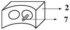
图3为本发明中的头戴显示设备与光敏传感器的安装示意图;3 is a schematic diagram of the installation of the head-mounted display device and the photosensitive sensor in the present invention;
图4为本发明中采用的光编码板的示意图;Fig. 4 is the schematic diagram of the optical coding plate adopted in the present invention;
图5为单次运动获得的检测波形和参考波形;Fig. 5 is the detection waveform and reference waveform obtained by a single movement;
图6为对图5的拟合波形;Fig. 6 is the fitting waveform to Fig. 5;
图7为多次往返运动过程中获得的检测波形和参考波形;Fig. 7 is the detection waveform and reference waveform obtained during the multiple round-trip motion;
图8为对图7的拟合波形。FIG. 8 is a fitting waveform to FIG. 7 .
其中,1-第一光敏传感器、2-头戴显示设备、3-载物台、4-数控导轨、5-导轨控制器、6-光编码板、7-第二光敏传感器。Among them, 1-first photosensitive sensor, 2-head mounted display device, 3-stage, 4-NC guide rail, 5-guide rail controller, 6-optical coding board, 7-second photosensitive sensor.
具体实施方式Detailed ways
下面结合附图并举实施例,对本发明进行详细描述。The present invention will be described in detail below with reference to the accompanying drawings and embodiments.
本发明的一种虚拟现实头戴显示设备的移动延迟测量方法,使用的测量装置如图2所示,包括第一光敏传感器1、头戴显示设备2、载物台3、高精度的数控导轨4、导轨控制器5、光编码板6以及第二光敏传感器7。数控导轨4的一侧放置光编码板6;如图4所示,光编码板6上设置有编码图形,编码图形为间隔排列的黑白条纹。数控导轨4的载物台3在导轨控制器5的控制下可沿轨道直线运动,第一光敏传感器1和头戴显示设备2固定在载物台3上,其中,第一光敏传感器1在跟随载物台3运动过程中可感知光编码板6上的黑白条纹,如图3所示,第二光敏传感器7固定在头戴显示设备2的显示窗口上;A method for measuring the movement delay of a virtual reality head-mounted display device of the present invention uses a measuring device as shown in FIG. 2, including a first
本发明的移动延迟测量方法具体步骤如下:The specific steps of the mobile delay measurement method of the present invention are as follows:
1、先控制载物台3从初始位置沿数控导轨4匀速运动,此时头戴显示设备2中不输入图像,但是时刻计算自身位置;1. First, control the
2、在载物台3运动过程中,第一光敏传感器1感知编码板6上的黑白条纹,在感知到黑条纹转变到白条纹,以及白条纹转变到黑条纹的转换时刻,头戴显示设备2计算出在各个转换时刻的自身位置,并记录下来;其中,位置包括两种:黑条纹转变到白条纹的位置定义为黑到白位置,白条纹转变到黑条纹的位置定义为白到黑位置。2. During the movement of the
3、完成整个运动后,最终得到一组头戴显示设备2的位置数据集;3. After the entire movement is completed, a set of position data sets of the head-mounted
4、然后控制载物台3再次从初始位置开始移动,运动过程同时记录第一光敏传感器1与第二光敏传感器7返回的数据;4. Then control the
5、根据之前记录的位置数据集,头戴显示设备2结合计算的自身当前位置信息,头戴显示设备2显示对应的黑白画面,即:当计算的位置为白到黑位置,向头戴显示设备2输出黑色图案;当计算的位置为黑到白位置,向头戴显示设备2输出白色图案;其上的第二光敏传感器7在此过程中,感知头戴显示设备2镜头输出的黑白图像,当感知到白色图像时,第二光敏传感器7返回高电平,当感知到黑色图像时,第二光敏传感器7返回低电平;5. According to the previously recorded position data set, the head-mounted
6、与此同时,第一光敏传感器1在移动过程中感知光编码板6上的编码图形,感知到白色条纹时,第一光敏传感器1返回高电平,当感知到黑色条纹时,第一光敏传感器1返回低电平;6. At the same time, the first
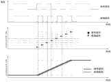
7、完成移动后,得到两组起点时刻完全一致的方波信号,如图5所示,方波信号中部的图形,就是编码区的返回信号;由于本发明还在编码区两端增加了区分运动方向的信息头,图5中信号两端为信息头返回信号;由第一光敏传感器1返回的波形称之为参考波形,由第二光敏传感器7返回的波形称之为检测波形。7, after completing the movement, obtain the square wave signal that two groups of starting points are completely consistent, as shown in Figure 5, the figure in the middle of the square wave signal is the return signal of the coding area; because the present invention also adds distinction at both ends of the coding area. For the information head in the moving direction, both ends of the signal in Figure 5 are the return signal of the information head; the waveform returned by the
8、数据处理:由于头戴显示设备2解算位置时有时间延迟,当载物台3运动到某位置时,头戴显示设备2不能马上感知到该位置,有一个时间延迟,因此,如图5所示,检测波形相对于参考波形就会有一个时间延迟Δt;因此,计算出该时间延迟Δt即得到了头戴显示设备2的时间延迟。通过对检测波形与参考波形上多个时间延迟Δt求平均值,可以得到更精确的头戴显示设备2的移动延迟。8. Data processing: Since there is a time delay when the head-mounted
为了增加多次取平均的数据量,本发明中,对参考波形和检测波形进行线性拟合,然后进行采样,以获得更多数据量,具体方法为:In order to increase the amount of data averaged multiple times, in the present invention, linear fitting is performed on the reference waveform and the detection waveform, and then sampling is performed to obtain more data amount, and the specific method is as follows:
A、从左到右依次给光编码板6上编码区部分的黑白条纹图案的分界线赋予编号,即1号分界线、2号分界线等;则基于光编码板6获得的参考波形、与参考波形对应的检测波形的各个跳变沿(上升沿和下降沿)也对应取得了编号。A, sequentially from left to right give numbers to the dividing line of the black and white striped pattern of the coding area part on the
B、以时间为x轴,编号为y轴建立坐标系,以参考波形方波跳变沿的时间信息为x坐标,以跳变沿的编号值为y坐标,以此在坐标系中绘制得到表征跳变沿编号和时间的离散点;同理,得到检测波形各跳变沿对应的离散点。B. Take the time as the x-axis and the number as the y-axis to establish a coordinate system, take the time information of the jumping edge of the reference waveform square wave as the x-coordinate, and use the number of the jumping edge as the y-coordinate to draw in the coordinate system The discrete points representing the transition edge number and time; similarly, the discrete points corresponding to each transition edge of the detected waveform are obtained.
C、分别对两组离散点进行线性拟合,得到两条曲线,通过对y值进行设定步长的采样,得到同一y值下两曲线间x轴的坐标差值,即检测波形相对于参考波形的一个延迟时间数据;对y轴有效区间进行多次采样后,得到大量延迟时间数据并求取均值,即可得更精确的时间延迟量。C. Perform linear fitting on the two sets of discrete points respectively to obtain two curves. By sampling the y value with a set step size, the coordinate difference of the x-axis between the two curves under the same y value is obtained, that is, the detected waveform is relative to the A delay time data of the reference waveform; after sampling the effective interval of the y-axis multiple times, a large amount of delay time data is obtained and the average value is obtained to obtain a more accurate time delay amount.
为进一步增加数据量,应当使头戴显示设备2在导轨4上往返运动,获得更多的检测波形和参考波形;但在往返运动中需要确定载物台3的运动方向,为了自动区分运动方向,在光编码板6的编码图形两端各设置一个信息头,由黑白条纹按一定排布顺序组合而成;两个信息头的黑白信号包含一定的方向性,用于反馈头戴显示设备2此时的移动是前进还是后退,图4中展示了一种光编码板6实现方案,按照白色为“1”黑色为“0”的编码方式,正向移动时光敏传感器感知的信息头信号为“11100”,反向移动则感知信号“00111”,以此区分不同运动方向。In order to further increase the amount of data, the head-mounted
往返运动多次后,利用光编码板6信号的方向性,判断该次运动是前进还是后退,前进时拟合曲线斜率为正,返回时拟合曲线斜率为负,得到图8所示的波形。至此,分组计算有效区域(1~8)内所有的时间延迟Δt,其均值即为设备的延迟时间T。After moving back and forth for many times, use the directionality of the signal of the
综上所述,以上仅为本发明的较佳实施例而已,并非用于限定本发明的保护范围。凡在本发明的精神和原则之内,所作的任何修改、等同替换、改进等,均应包含在本发明的保护范围之内。To sum up, the above are only preferred embodiments of the present invention, and are not intended to limit the protection scope of the present invention. Any modification, equivalent replacement, improvement, etc. made within the spirit and principle of the present invention shall be included within the protection scope of the present invention.
Claims (4)
Priority Applications (1)
| Application Number | Priority Date | Filing Date | Title |
|---|---|---|---|
| CN201811636718.4ACN109696191B (en) | 2018-12-29 | 2018-12-29 | Movement delay measurement method of virtual reality head-mounted display equipment |
Applications Claiming Priority (1)
| Application Number | Priority Date | Filing Date | Title |
|---|---|---|---|
| CN201811636718.4ACN109696191B (en) | 2018-12-29 | 2018-12-29 | Movement delay measurement method of virtual reality head-mounted display equipment |
Publications (2)
| Publication Number | Publication Date |
|---|---|
| CN109696191A CN109696191A (en) | 2019-04-30 |
| CN109696191Btrue CN109696191B (en) | 2020-06-30 |
Family
ID=66232365
Family Applications (1)
| Application Number | Title | Priority Date | Filing Date |
|---|---|---|---|
| CN201811636718.4AActiveCN109696191B (en) | 2018-12-29 | 2018-12-29 | Movement delay measurement method of virtual reality head-mounted display equipment |
Country Status (1)
| Country | Link |
|---|---|
| CN (1) | CN109696191B (en) |
Families Citing this family (3)
| Publication number | Priority date | Publication date | Assignee | Title |
|---|---|---|---|---|
| CN111243027B (en)* | 2020-02-28 | 2023-06-23 | 京东方科技集团股份有限公司 | Delay measurement method, device and system |
| CN112816183B (en)* | 2021-03-03 | 2022-09-06 | 广州计量检测技术研究院 | VR head-mounted display device movement characteristic detection device and method |
| CN114067577B (en)* | 2021-08-17 | 2025-04-25 | 北京工业大学 | A vehicle speed testing method and device based on optics |
Family Cites Families (16)
| Publication number | Priority date | Publication date | Assignee | Title |
|---|---|---|---|---|
| JP2006171637A (en)* | 2004-12-20 | 2006-06-29 | Canon Inc | Head-mounted image display device |
| US10018847B2 (en)* | 2015-10-28 | 2018-07-10 | Honeywell International Inc. | Methods of vestibulo-ocular reflex correction in display systems |
| WO2017081870A1 (en)* | 2015-11-12 | 2017-05-18 | パナソニック インテレクチュアル プロパティ コーポレーション オブ アメリカ | Display method, program and display device |
| CN105807602A (en)* | 2016-03-10 | 2016-07-27 | 北京小鸟看看科技有限公司 | Method and system for testing virtual reality equipment delay |
| CN105954007B (en)* | 2016-05-18 | 2018-10-02 | 杭州映墨科技有限公司 | Delay test system and method for virtual implementing helmet acceleration movement |
| CN107687932B (en)* | 2016-08-05 | 2020-08-04 | 成都理想境界科技有限公司 | Method and device for detecting delay of head-mounted display equipment |
| CN106325517A (en)* | 2016-08-29 | 2017-01-11 | 袁超 | Target object trigger method and system and wearable equipment based on virtual reality |
| US10565916B2 (en)* | 2016-09-09 | 2020-02-18 | Kt Corporation | Providing streaming of virtual reality contents |
| CN106644396B (en)* | 2016-12-16 | 2019-06-25 | 捷开通讯(深圳)有限公司 | The detection device and detection method of the delay time of VR glasses |
| US9807384B1 (en)* | 2017-01-13 | 2017-10-31 | Optofidelity Oy | Method, apparatus and computer program product for testing a display |
| CN107423212B (en)* | 2017-03-17 | 2020-12-01 | 深圳普瑞赛思检测技术有限公司 | Method and device for evaluating response delay of screen of virtual reality equipment |
| CN106951370B (en)* | 2017-03-17 | 2021-01-26 | 深圳普瑞赛思检测技术有限公司 | Evaluation method and device for virtual reality equipment program running delay |
| CN207248488U (en)* | 2017-10-18 | 2018-04-17 | 宁波神州泰岳锐智信息科技有限公司 | For testing the revolution speed control device of VR equipment delay |
| CN107820075A (en)* | 2017-11-27 | 2018-03-20 | 中国计量大学 | A kind of VR equipment delayed test devices based on light stream camera |
| CN208156648U (en)* | 2018-02-11 | 2018-11-27 | 深圳创维新世界科技有限公司 | Time delay measurement instrument |
| CN108283793B (en)* | 2018-03-10 | 2023-08-01 | 杭州虚现科技股份有限公司 | An omnidirectional mobile platform and a method for accurately tracking both feet information based on the platform |
- 2018
- 2018-12-29CNCN201811636718.4Apatent/CN109696191B/enactiveActive
Also Published As
| Publication number | Publication date |
|---|---|
| CN109696191A (en) | 2019-04-30 |
Similar Documents
| Publication | Publication Date | Title |
|---|---|---|
| CN109696191B (en) | Movement delay measurement method of virtual reality head-mounted display equipment | |
| EP2584527B1 (en) | Three dimensional measurement apparatus, control method and program therefor | |
| US9945698B2 (en) | Macro-micro composite grating ruler measuring system and measuring method using same comprising a macro-scale reading module, a micro-scale reading module and a measuring reference line | |
| KR101605224B1 (en) | Method and apparatus for obtaining depth information using optical pattern | |
| CN102508578A (en) | Projection positioning device and method as well as interaction system and method | |
| KR20080047392A (en) | Method and circuit arrangement for recognizing and tracking the eyes of some observers in real time | |
| KR100907104B1 (en) | Pointing point calculation method and apparatus, and remote collaboration system comprising the apparatus | |
| TW201643617A (en) | Method and system for estimating finger movement | |
| CN106406638B (en) | Touch point contour generation method and equipment | |
| CN112816183B (en) | VR head-mounted display device movement characteristic detection device and method | |
| CN103197774A (en) | Method and system for mapping application track of emission light source motion track | |
| US7119323B1 (en) | Error corrected optical navigation system | |
| CN111121637A (en) | Grating displacement detection method based on pixel coding | |
| US20250199628A1 (en) | Pen state detection circuit and method, and input system | |
| CN115122333B (en) | Robot calibration method, device, electronic device and storage medium | |
| CN109752097B (en) | A movement delay measurement method for a VR helmet based on a laser tube | |
| CN109632263B (en) | Method for measuring movement delay of VR helmet based on grating ruler | |
| CN109765035B (en) | Mobile delay measurement method of VR helmet based on gradient coding | |
| CN104866143B (en) | The determination method, apparatus and touch-screen equipment of a kind of touch point | |
| CN109696190B (en) | Method for measuring rotation delay of VR helmet based on gradient coding | |
| CN104375715B (en) | Optical touch positioning method and system and optical touch positioner | |
| CN102798382B (en) | Embedded vision positioning system | |
| CN109696189B (en) | A rotational delay measurement method for an encoder-based VR helmet | |
| CN109737997B (en) | A method for measuring rotation delay of virtual reality head-mounted display device | |
| US20150109258A1 (en) | Optical touch system, method of touch detection, and computer program product |
Legal Events
| Date | Code | Title | Description |
|---|---|---|---|
| PB01 | Publication | ||
| PB01 | Publication | ||
| SE01 | Entry into force of request for substantive examination | ||
| SE01 | Entry into force of request for substantive examination | ||
| GR01 | Patent grant | ||
| GR01 | Patent grant |